KR101848903B1 - Sliding mode controller for dual active bridge converter - Google Patents
Sliding mode controller for dual active bridge converterDownload PDFInfo
- Publication number
- KR101848903B1 KR101848903B1KR1020160157684AKR20160157684AKR101848903B1KR 101848903 B1KR101848903 B1KR 101848903B1KR 1020160157684 AKR1020160157684 AKR 1020160157684AKR 20160157684 AKR20160157684 AKR 20160157684AKR 101848903 B1KR101848903 B1KR 101848903B1
- Authority
- KR
- South Korea
- Prior art keywords
- battery
- voltage
- dual active
- equation
- current
- Prior art date
- Legal status (The legal status is an assumption and is not a legal conclusion. Google has not performed a legal analysis and makes no representation as to the accuracy of the status listed.)
- Active
Links
- 230000009977dual effectEffects0.000titleclaimsabstractdescription57
- 238000000034methodMethods0.000claimsdescription8
- 238000006243chemical reactionMethods0.000abstractdescription5
- 238000010586diagramMethods0.000description9
- 238000004146energy storageMethods0.000description6
- 230000010363phase shiftEffects0.000description6
- 230000001131transforming effectEffects0.000description4
- 238000002474experimental methodMethods0.000description3
- 239000003990capacitorSubstances0.000description2
- 230000007423decreaseEffects0.000description2
- 230000014509gene expressionEffects0.000description2
- 230000002411adverseEffects0.000description1
- 230000002238attenuated effectEffects0.000description1
- 230000002146bilateral effectEffects0.000description1
- 244000145845chatteringSpecies0.000description1
- 238000010276constructionMethods0.000description1
- 238000002955isolationMethods0.000description1
- 238000005070samplingMethods0.000description1
- 238000004804windingMethods0.000description1
Images


Classifications
- H—ELECTRICITY
- H02—GENERATION; CONVERSION OR DISTRIBUTION OF ELECTRIC POWER
- H02M—APPARATUS FOR CONVERSION BETWEEN AC AND AC, BETWEEN AC AND DC, OR BETWEEN DC AND DC, AND FOR USE WITH MAINS OR SIMILAR POWER SUPPLY SYSTEMS; CONVERSION OF DC OR AC INPUT POWER INTO SURGE OUTPUT POWER; CONTROL OR REGULATION THEREOF
- H02M3/00—Conversion of DC power input into DC power output
- H02M3/22—Conversion of DC power input into DC power output with intermediate conversion into AC
- H02M3/24—Conversion of DC power input into DC power output with intermediate conversion into AC by static converters
- H02M3/28—Conversion of DC power input into DC power output with intermediate conversion into AC by static converters using discharge tubes with control electrode or semiconductor devices with control electrode to produce the intermediate AC
- H02M3/325—Conversion of DC power input into DC power output with intermediate conversion into AC by static converters using discharge tubes with control electrode or semiconductor devices with control electrode to produce the intermediate AC using devices of a triode or a transistor type requiring continuous application of a control signal
- H02M3/335—Conversion of DC power input into DC power output with intermediate conversion into AC by static converters using discharge tubes with control electrode or semiconductor devices with control electrode to produce the intermediate AC using devices of a triode or a transistor type requiring continuous application of a control signal using semiconductor devices only
- H02M3/33569—Conversion of DC power input into DC power output with intermediate conversion into AC by static converters using discharge tubes with control electrode or semiconductor devices with control electrode to produce the intermediate AC using devices of a triode or a transistor type requiring continuous application of a control signal using semiconductor devices only having several active switching elements
- H02M3/33576—Conversion of DC power input into DC power output with intermediate conversion into AC by static converters using discharge tubes with control electrode or semiconductor devices with control electrode to produce the intermediate AC using devices of a triode or a transistor type requiring continuous application of a control signal using semiconductor devices only having several active switching elements having at least one active switching element at the secondary side of an isolation transformer
- H—ELECTRICITY
- H02—GENERATION; CONVERSION OR DISTRIBUTION OF ELECTRIC POWER
- H02M—APPARATUS FOR CONVERSION BETWEEN AC AND AC, BETWEEN AC AND DC, OR BETWEEN DC AND DC, AND FOR USE WITH MAINS OR SIMILAR POWER SUPPLY SYSTEMS; CONVERSION OF DC OR AC INPUT POWER INTO SURGE OUTPUT POWER; CONTROL OR REGULATION THEREOF
- H02M1/00—Details of apparatus for conversion
- H02M1/0003—Details of control, feedback or regulation circuits
- H—ELECTRICITY
- H02—GENERATION; CONVERSION OR DISTRIBUTION OF ELECTRIC POWER
- H02M—APPARATUS FOR CONVERSION BETWEEN AC AND AC, BETWEEN AC AND DC, OR BETWEEN DC AND DC, AND FOR USE WITH MAINS OR SIMILAR POWER SUPPLY SYSTEMS; CONVERSION OF DC OR AC INPUT POWER INTO SURGE OUTPUT POWER; CONTROL OR REGULATION THEREOF
- H02M1/00—Details of apparatus for conversion
- H02M1/08—Circuits specially adapted for the generation of control voltages for semiconductor devices incorporated in static converters
- H02J2007/0059—
- H02M2001/0003—
Landscapes
- Engineering & Computer Science (AREA)
- Power Engineering (AREA)
- Dc-Dc Converters (AREA)
Abstract
Translated fromKoreanDescription
Translated fromKorean본 발명의 실시예들은 듀얼 엑티브 브릿지(DAB : Dual Active Bridge) 컨버터를 위한 슬라이딩 모드 제어 기술과 관련된다.Embodiments of the invention relate to a sliding mode control technique for a dual active bridge (DAB) converter.
듀얼 엑티브 브릿지 컨버터는 절연 및 전압의 크기를 변환하는 역할을 하며, 일반적으로는 단일 위상 천이 변조(Single Phase Shift Modulation) 방식으로 동작된다.The dual active bridge converter serves to convert the magnitude of the isolation and voltage, and typically operates in a single phase shift modulation (PWM) scheme.
이러한 듀얼 엑티브 브릿지 컨버터를 활용한 배터리 에너지 저장장치는, 에너지 저장 장치의 운용을 위해 출력 캐패시터의 전압, 출력 인덕터의 전류 제어가 필요하다.Battery energy storage devices utilizing such dual active bridge converters require the voltage of the output capacitor and the current control of the output inductor to operate the energy storage device.
이와 관련하여, 슬라이딩 모드 제어가 연구 되었으나, 기존 슬라이딩 모드 제어 방식은 큰 오버슛(overshot), 정상상태 오차 및 채터링(chattering) 현상 등의 문제가 있다.In this regard, although the sliding mode control has been studied, the existing sliding mode control method has problems such as a large overshoot, a steady state error, and a chattering phenomenon.
본 발명의 실시예들은 기존 슬라이딩 모드 제어 방식의 문제점들을 해소하여 높은 정상 상태 안정성을 보장하고, 빠른 응답 속도를 보이며, 부하 변동에 강인한 성능을 가지는 슬라이딩 모드 제어기를 제공하기 위한 것이다.Embodiments of the present invention provide a sliding mode controller that resolves problems of existing sliding mode control schemes, assures high steady state stability, exhibits a fast response speed, and has robust performance against load variations.
본 발명의 일 실시예에 따른 슬라이딩 모드 제어기는, 듀얼 엑티브 브릿지(DAB : Dual Active Bridge) 컨버터, 상기 듀얼 엑티브 브릿지 컨버터에 연결되는 배터리, 및 상기 컨버터와 상기 배터리 사이에 배치되는 인덕터(Lf)를 포함하는 시스템 내 상기 배터리의 전압(vb)에 대한 방정식 또는 상기 배터리에 흐르는 전류(ib)에 대한 방정식을 외란항(disturbance term)을 포함하는 상태 방정식으로 변환하는 변환부, 상기 전압과 지령전압 간의 차 또는 상기 전류와 지령전류 간의 차를 오차로 설정하고, 상기 오차, 상기 오차의 적분항 및 상기 오차의 이중 적분항을 포함하는 슬라이딩 평면 함수를 획득하는 함수 획득부, 및 상기 상태 방정식을 이용하여 상기 슬라이딩 평면 함수의 미분값이 0이 되게 하는 등가 입력(ueq)를 계산하고, 상기 등가 입력(ueq)을 이용하여 상기 듀얼 엑티브 브릿지 컨버터를 제어하는 제어부를 포함한다.A sliding mode controller according to an embodiment of the present invention includes a dual active bridge (DAB) converter, a battery connected to the dual active bridge converter, and an inductor Lf disposed between the converter and the battery. A transform unit for converting an equation for a voltage (vb ) of the battery in the system or an equation for a current (ib ) flowing in the battery into a state equation including a disturbance term, A function obtaining section for setting a difference between command voltages or a difference between the current and command current as an error and obtaining a sliding plane function including the error, the integral term of the error and the double integral term of the error, the use in calculating the equivalent input (ueq) to a differential value of the sliding plane function to zero, take advantage of the equivalent input (ueq) A control unit for controlling the dual active bridge converter.
상기 외란항은, 상기 배터리의 전압(vb)에 대한 방정식의 경우 상기 듀얼 엑티브 브릿지 컨버터의 배터리측 전류(is)에 관한 항이며, 상기 배터리에 흐르는 전류(ib)에 대한 방정식의 경우 상기 배터리의 전압(vb)에 관한 항일 수 있다.The disturbance term is a term relating to the battery side current (is ) of the dual active bridge converter in the case of the equation for the voltage (vb ) of the battery, and in the case of the equation for the current (ib ) flowing in the battery (Vb ) of the battery.
상기 상태 방정식은, 하기 수학식으로 표시될 수 있다.The state equation can be expressed by the following equation.

(여기서, x는 상기 배터리의 전압(vb) 또는 상기 배터리에 흐르는 전류(ib), f는 x에 관한 항, g는 상기 듀얼 엑티브 브릿지 컨버터의 출력측 전압 (vdc)에 관한 항, u는 제어 입력에 관한 항, E는 외란항)Where x is the voltage of the battery (vb ) or current flowing through the battery (ib ), f is a term relating to x, g is a term relating to the output side voltage (vdc ) of the dual active bridge converter, u Is a term relating to a control input, and E is a disturbance term)
상기 슬라이딩 평면 함수는, 하기 수학식으로 표시될 수 있다.The sliding plane function can be expressed by the following equation.

(여기서, e는 오차(x-xd), x는 상기 배터리의 전압(vb) 또는 상기 배터리에 흐르는 전류(ib), xd는 지령전압 또는 지령전류, k1, k2는 양의 값을 가지는 제어 이득)(Where, e is the error (xxd), x is the voltage of the battery (vb) or the current flowing through the battery (ib), xd is a command voltage or command current, k1, k2 is a positive value of / RTI >
본 발명의 일 실시예들에 따르면, 외란항을 포함하는 상태방정식 및 적분항을 포함하는 슬라이딩 평면 함수로부터 등가 입력을 계산하여 듀얼 엑티브 브릿지 컨버터를 제어함으로써, 듀얼 엑티브 브릿지 컨버터의 동특성을 향상시킬 수 있다.According to one embodiment of the present invention, dynamic characteristics of a dual active bridge converter can be improved by controlling the dual active bridge converter by calculating an equivalent input from a sliding plane function including a state equation including a disturbance term and an integral term have.
또한, 본 발명의 일 실시예들에 따르면, 계산된 등가 입력을 이용하여 듀얼 엑티브 브릿지 컨버터를 제어함으로써 듀얼 엑티브 브릿지 컨버터가 외란에 강인하도록 할 수 있으며, 듀얼 엑티브 브릿지 컨버터의 정상상태 오차가 0으로 수렴하도록 할 수 있다.Also, according to one embodiment of the present invention, the dual active bridge converter can be made robust to disturbance by controlling the dual active bridge converter using the calculated equivalent input, and the steady state error of the dual active bridge converter is set to zero Convergence.
도 1은 본 발명의 일 실시예에 따른 슬라이딩 모드 제어기의 블록도
도 2는 본 발명의 일 실시예에 따른 인덕터가 추가 배치된 듀얼 엑티브 브릿지 컨버터의 회로도
도 3은 본 발명의 일 실시예에 따른 슬라이딩 모드 제어기의 블록도
도 4은 일반적인 듀얼 엑티브 브릿지 컨버터의 동작을 설명하기 위한 도면
도 5는 본 발명의 일 실시예에 따른 슬라이딩 모드 제어기를 이용한 에너지 저장 장치의 실험을 위한 구성을 나타내는 도면
도 6 내지 도 13은 본 발명의 일 실시예에 따른 슬라이딩 모드 제어기의 실험 결과를 나타내는 도면1 is a block diagram of a sliding mode controller according to an embodiment of the present invention;
2 is a circuit diagram of a dual active bridge converter in which an inductor is additionally arranged according to an embodiment of the present invention.
3 is a block diagram of a sliding mode controller according to an embodiment of the present invention.
4 is a diagram for explaining the operation of a general dual active bridge converter
5 is a diagram illustrating a configuration for an experiment of an energy storage device using a sliding mode controller according to an embodiment of the present invention.
6 to 13 are graphs showing experimental results of a sliding mode controller according to an embodiment of the present invention.
이하, 도면을 참조하여 본 발명의 구체적인 실시형태를 설명하기로 한다. 이하의 상세한 설명은 본 명세서에서 기술된 방법, 장치 및/또는 시스템에 대한 포괄적인 이해를 돕기 위해 제공된다. 그러나 이는 예시에 불과하며 본 발명은 이에 제한되지 않는다.Hereinafter, specific embodiments of the present invention will be described with reference to the drawings. The following detailed description is provided to provide a comprehensive understanding of the methods, apparatus, and / or systems described herein. However, this is merely an example and the present invention is not limited thereto.
본 발명의 실시예들을 설명함에 있어서, 본 발명과 관련된 공지기술에 대한 구체적인 설명이 본 발명의 요지를 불필요하게 흐릴 수 있다고 판단되는 경우에는 그 상세한 설명을 생략하기로 한다. 그리고, 후술되는 용어들은 본 발명에서의 기능을 고려하여 정의된 용어들로서 이는 사용자, 운용자의 의도 또는 관례 등에 따라 달라질 수 있다. 그러므로 그 정의는 본 명세서 전반에 걸친 내용을 토대로 내려져야 할 것이다. 상세한 설명에서 사용되는 용어는 단지 본 발명의 실시예들을 기술하기 위한 것이며, 결코 제한적이어서는 안 된다. 명확하게 달리 사용되지 않는 한, 단수 형태의 표현은 복수 형태의 의미를 포함한다. 본 설명에서, "포함" 또는 "구비"와 같은 표현은 어떤 특성들, 숫자들, 단계들, 동작들, 요소들, 이들의 일부 또는 조합을 가리키기 위한 것이며, 기술된 것 이외에 하나 또는 그 이상의 다른 특성, 숫자, 단계, 동작, 요소, 이들의 일부 또는 조합의 존재 또는 가능성을 배제하도록 해석되어서는 안 된다.DETAILED DESCRIPTION OF THE PREFERRED EMBODIMENTS Hereinafter, exemplary embodiments of the present invention will be described in detail with reference to the accompanying drawings. In the following description, well-known functions or constructions are not described in detail since they would obscure the invention in unnecessary detail. The following terms are defined in consideration of the functions of the present invention, and may be changed according to the intention or custom of the user, the operator, and the like. Therefore, the definition should be based on the contents throughout this specification. The terms used in the detailed description are intended only to describe embodiments of the invention and should in no way be limiting. Unless specifically stated otherwise, the singular forms of the expressions include plural forms of meanings. In this description, the expressions "comprising" or "comprising" are intended to indicate certain features, numbers, steps, operations, elements, parts or combinations thereof, Should not be construed to preclude the presence or possibility of other features, numbers, steps, operations, elements, portions or combinations thereof.
도 1은 본 발명의 일 실시예에 따른 슬라이딩 모드 제어기의 블록도이며, 도 2는 본 발명의 일 실시예에 따른 인덕터가 추가 배치된 듀얼 엑티브 브릿지(DAB : Dual Active Bridge) 컨버터의 회로도이다.FIG. 1 is a block diagram of a sliding mode controller according to an embodiment of the present invention, and FIG. 2 is a circuit diagram of a dual active bridge (DAB) converter in which an inductor is additionally disposed according to an embodiment of the present invention.
도 1 및 도 2를 참조하면, 본 발명의 일 실시예에 따른 슬라이딩 모드 제어기(100)는 슬라이딩 모드 제어 기법을 이용하여 듀얼 엑티브 브릿지(DAB : Dual Active Bridge) 컨버터를 제어하는 제어기에 관한 것으로, 변환부(110), 함수 획득부(120) 및 제어부(130)를 포함한다. 또한, 듀얼 엑티브 브릿지 컨버터는, 배터리(201) 및 듀얼 엑티브 브릿지 컨버터와 배터리(201) 사이에 연결되는 인덕터(202)와 연결될 수 있다.Referring to FIGS. 1 and 2, a
변환부(110)는 듀얼 엑티브 브릿지 컨버터, 듀얼 엑티브 브릿지 컨버터에 연결되는 배터리(201), 및 듀얼 엑티브 브릿지 컨버터와 배터리 사이에 배치되는 인덕터(202)를 포함하는 시스템(10) 내 배터리의 전압(vb)에 대한 방정식 또는 배터리에 흐르는 전류(ib)에 대한 방정식을 외란항(disturbance term)을 포함하는 상태 방정식으로 변환한다. 본 실시예들에 있어서, 시스템(10)은 예를 들어, 배터리 에너지 저장장치 시스템(BESS : Bettery Energy Storage System)일 수 있다.The
구체적으로, 변환부(110)는 듀얼 엑티브 브릿지 컨버터, 배터리(201) 및 인덕터(202)가 연결된 시스템(10)의 회로에서 키르히호프의 법칙 등을 이용하여 배터리의 전압(vb)에 대한 방정식 또는 배터리에 흐르는 전류(ib)에 대한 방정식을 도출할 수 있다.Specifically, the
일 예시로서, 배터리의 전압(vb)에 대한 방정식은 하기 수학식 1로 표현되는 방정식일 수 있다.As an example, the equation for the voltage (vb ) of the battery may be an equation expressed by the following equation (1).
[수학식 1][Equation 1]

이때,


다른 예시로서, 배터리에 흐르는 전류(ib)에 대한 방정식은 하기 수학식 2로 표현되는 방정식일 수 있다. 이때, 하기 수학식 2는 시스템(10)의 회로에서 배터리의 전압(vb)에 대한 방정식을 도출하고, 인덕터(202)의 내부 저항(Rf)이 매우 작다고 가정하여 도출된 방정식일 수 있다.As another example, the equation for the current (ib ) flowing in the battery may be an equation expressed by the following equation (2).
[수학식 2]&Quot; (2) "

이때, ib는 배터리에 흐르는 전류, Lf는 듀얼 엑티브 브릿지 컨버터와 배터리 사이에 배치되는 인덕터의 인덕턴스, Rf는 듀얼 엑티브 브릿지 컨버터와 배터리 사이에 배치되는 인덕터의 내부저항, Vb는 배터리의 전압을 나타낸다.At this time, ib is a current flowing through the battery, Lf is the internal resistance of the inductor disposed between the dual active bridge converter and the inductance of the inductor disposed between the battery, Rf is a dual active bridge converter and the battery, Vb is the battery Voltage.
또한, 변환부(110)는 도출된 방정식을 외란항을 포함하는 상태 방정식으로 변환할 수 있다. 이때, 외란항은 시스템(10)에 영향을 끼치는 외부 요인으로서 도출된 방정식의 변수에 따라 달라질 수 있다. 구체적으로, 외란항은 배터리의 전압(vb)에 대한 방정식의 경우 듀얼 엑티브 브릿지 컨버터의 배터리측 전류(is)에 관한 항이며, 배터리에 흐르는 전류(ib)에 대한 방정식의 경우 배터리의 전압(vb)에 관한 항일 수 있다.In addition, the
구체적으로, 변환부(110)는 도출한 방정식을 하기 수학식 3으로 표현되는 상태 방정식으로 변환할 수 있다.Specifically, the
[수학식 3]&Quot; (3) "

여기서, x는 상기 배터리의 전압(vb) 또는 상기 배터리에 흐르는 전류(ib), f는 x에 관한 항, g는 상기 듀얼 엑티브 브릿지 컨버터의 출력측 전압 (vdc)에 관한 항, u는 제어 입력에 관한 항, E는 외란항을 나타낸다.Here, x is a voltage (vb ) of the battery or a current (ib ) flowing in the battery, f is a term relating to x, g is a term relating to an output side voltage (vdc ) of the dual active bridge converter, The term related to the control input, and E denotes the disturbance term.
예를 들어, 변환부(110)는 수학식 1로 표현된 방정식을 수학식 3으로 변환하여, x=vb,


또한, 예를 들어 변환부(110)는 수학식 2로 표현된 방정식을 수학식 3으로 변환하여, x=ib,


함수 획득부(120)는 배터리의 전압(vb)과 지령전압 간의 차 또는 배터리에 흐르는 전류(ib)와 지령전류 간의 차를 오차로 설정하고, 설정한 오차, 설정한 오차의 적분항 및 설정한 오차의 이중 적분항을 포함하는 슬라이딩 평면 함수를 획득한다. 이때, 지령전압은 출력하고자 하는 목표 전압으로서, 예를 들어 250v일 수 있다. 또한, 지령전류는 출력하고자 하는 목표 전류로서, 예를 들어 7A일 수 있다. 또한, 지령전압 및 지령전류는 예를 들어 시스템(10) 관리자에 의해 미리 설정된 값일 수 있다.The
구체적으로, 함수 획득부(120)는 하기 수학식 4로 표현되는 슬라이딩 평면 함수를 획득할 수 있다.Specifically, the
[수학식 4]&Quot; (4) "

이때, e는 오차(x-xd), x는 배터리의 전압(vb) 또는 배터리에 흐르는 전류(ib), xd는 지령전압 또는 지령전류, k1, k2는 양의 값을 가지는 제어 이득을 나타낸다. 또한, k1, k2는 예를 들어, 시스템(10) 관리자에 의해 미리 설정된 값을 가지는 상수일 수 있다.At this time, e is the error (xxd), x is the voltage of the battery (vb), or the current flowing through the battery (ib), xd is a command voltage or command current, k1, k2 is the control having a positive value Respectively. K1 , k2 may be a constant having a value preset by the
예를 들어, 함수 획득부(120)는 오차(e)를 배터리의 전압(vb)과 지령 전압(vbd)간의 차로 설정하고, 위와 같은 슬라이딩 평면 함수를 획득할 수 있다. 또한, 예를 들어 함수 획득부(120)는 오차(e)를 배터리에 흐르는 전류(ib)와 지령 전류(ibd)간의 차로 설정하고, 위와 같은 슬라이딩 평면 함수를 획득할 수 있다.For example, the
제어부(130)는 상태 방정식을 이용하여 슬라이딩 평면 함수의 미분값이 0이 되게 하는 등가 입력(ueq)을 계산하고, 등가 입력(ueq)을 이용하여 듀얼 엑티브 브릿지 컨버터를 제어한다.The
구체적으로, 제어부(130)는 변환부(110)로부터 변환된 상태 방정식을 전달 받고, 함수 획득부(120)로부터 획득한 슬라이딩 평면 함수를 전달 받을 수 있다.Specifically, the
또한, 제어부(130)는 획득한 슬라이딩 평면 함수로부터 슬라이딩 평면 함수의 미분값이 0이 되게 하는 등가 입력(ueq)을 계산할 수 있다. 예를 들어, 제어부(130)는 수학식 4로 표현되는 슬라이딩 평면 함수를 미분하여, 하기 수학식 5로 표현되는 슬라이딩 평면 함수의 미분 방정식을 계산할 수 있다.Also, the
[수학식 5]&Quot; (5) "

또한, 제어부(130)는 수학식 3으로 표현된 상태 방정식 및 수학식 5로 표현된 슬라이딩 평면 함수의 미분 방정식을 이용하여 하기 수학식 6으로 표현되는 등가 입력(ueq)을 계산할 수 있다.Also, the
[수학식 6]&Quot; (6) "

또한, 제어부(130)는 제어하고자 하는 시스템(10)의 상태를 슬라이딩 평면으로 수렴하게 하기 위해, 상기 수학식 6으로 표현된 등가 입력(ueq)에 부호 함수(sign function)를 더하여 하기 수학식 7로 표현된 등가 입력(ueq)을 계산할 수 있다.In order to converge the state of the
[수학식 7]&Quot; (7) "

이때, k3는 제어 이득일 수 있다.At this time, k3 may be a control gain.
또한, 제어부(130)는 리아프노브 함수(Lyapunov function)(W)를 이용하여, 제어 이득 k3의 부호를 결정할 수 있다. 구체적으로, 제어부(130)는 하기 수학식 8로 표현된 리아프노브 함수가 음의 값을 가지도록 k3의 부호를 결정할 수 있다.Also, the
[수학식 8]&Quot; (8) "
도 3은 본 발명의 일 실시예에 따른 슬라이딩 모드 제어기의 블록도이다.3 is a block diagram of a sliding mode controller in accordance with an embodiment of the present invention.
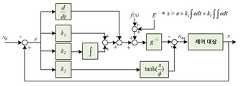
도 3을 참조하면, 본 발명의 일 실시예에 따른 슬라이딩 모드 제어기는, x(배터리의 전압(vb) 또는 배터리에 흐르는 전류(ib)), xd(지령전압 또는 지령전류), E(외란항)을 이용하여 등가 입력(ueq)를 계산하고, 이를 입력으로 제어 대상을 제어할 수 있다. 이때, 부호 함수는 실제적인 구현을 위해
구체적으로, 본 발명의 일 실시예에 따른 슬라이딩 모드 제어기는, 수학식 7로 표현된 등가 입력(ueq)를 계산하여, 제어 대상을 제어할 수 있다. 등가 입력(ueq)을 이용한 구체적인 제어 방법은 도 4에서 상세히 설명하기로 한다.Specifically, the sliding mode controller according to an embodiment of the present invention can control the controlled object by calculating the equivalent input ueq expressed by Equation (7). A concrete control method using the equivalent input (ueq ) will be described in detail with reference to FIG.
도 4은 일반적인 듀얼 엑티브 브릿지 컨버터의 동작을 설명하기 위한 도면이다.4 is a view for explaining the operation of a general dual active bridge converter.
도 4을 참조하면, 일반적으로 사용되는 듀얼 엑티브 브릿지 컨버터는 단일 위상 천이 변조(SPSM : Single Phase Shift Modulation) 방식으로 동작할 수 있다. 이때, v1은 변압기 1차측의 전압, v2는 변압기 2차측의 전압, Ts는 샘플링 주기를 나타낸다.Referring to FIG. 4, a commonly used dual active bridge converter can operate in a single phase shift modulation (SPSM) scheme. In this case, v1 denotes the voltage of the primary side of the transformer, v2 denotes the voltage of the secondary side of the transformer, and Ts denotes the sampling period.
구체적으로, 듀얼 엑티브 브릿지 컨버터는 변압기 양측 전압의 위상차(
이와 관련하여, 제어부(130)는 변압기 양측 전압의 위상차(
구체적으로, 제어부(130)는 수학식 7로 표현된 등가 입력(ueq)를 이용하여, 변압기 양측 전압의 위상차(
만약, 제어부(130)가 수학식 1로 표현된 방정식으로부터 변환된 상태 방정식을 전달받은 경우, 제어부(130)는 하기 수학식 9로 표현된 전압의 위상차(


[수학식 9]&Quot; (9) "

한편, 듀얼 엑티브 브릿지 컨버터는 좌우 대칭 구조를 가지므로, 제어부(130)는 배터리의 전압(vb) 제어와 동일한 방식으로, 듀얼 엑티브 브릿지 컨버터의 출력측 전압(vdc)을 제어할 수 있다.Meanwhile, since the dual active bridge converter has a bilateral symmetrical structure, the
또한 만약, 제어부(130)가 수학식 2로 표현된 방정식으로부터 변환된 상태 방정식을 전달받은 경우, 제어부(130)는 하기 수학식 10으로 표현된 전압의 위상차(


[수학식 10]&Quot; (10) "

도 5는 본 발명의 일 실시예에 따른 슬라이딩 모드 제어기를 이용한 에너지 저장 장치의 실험을 위한 구성을 나타내는 도면이다.5 is a diagram illustrating a configuration for an experiment of an energy storage device using a sliding mode controller according to an embodiment of the present invention.
도 5를 참조하면, 본 발명의 일 실시예에 따른 슬라이딩 모드 제어기를 이용한 에너지 저장 장치의 실험을 위한 구성은 DC 버스(직류 버스)에 전원 공급을 위한 AC(Alternating Current)/DC(Direct Current) 컨버터, 배터리 시뮬레이터, 듀얼 엑티브 브릿지 컨버터, 부하 및 제어보드로 구성될 수 있다.Referring to FIG. 5, an apparatus for testing an energy storage device using a sliding mode controller according to an embodiment of the present invention includes an alternating current (AC) / direct current (DC) circuit for supplying power to a DC bus Converter, battery simulator, dual active bridge converter, load and control board.
도 6 내지 도 13은 본 발명의 일 실시예에 따른 슬라이딩 모드 제어기의 실험 결과를 나타내는 도면이다. 구체적으로, 도 6 내지 도 11은 본 발명의 일 실시예에 따른 슬라이딩 모드 제어기를 적용한 듀얼 엑티브 브릿지 컨버터의 전압 제어 성능을 나타낸다. 또한, 도 12 내지 도 13은 본 발명의 일 실시예에 따른 슬라이딩 모드 제어기를 적용한 듀얼 엑티브 브릿지 컨버터의 전류 제어 성능을 나타낸다.6 to 13 are graphs showing experimental results of a sliding mode controller according to an embodiment of the present invention. 6 to 11 show voltage control performance of a dual active bridge converter to which a sliding mode controller according to an embodiment of the present invention is applied. 12 to 13 illustrate current control performance of a dual active bridge converter to which a sliding mode controller according to an embodiment of the present invention is applied.
한편, 도 6 내지 도 13에 도시된 실험 결과를 얻기 위해 사용된 실험 파라미터는 아래 표 1과 같다On the other hand, the experimental parameters used to obtain the experimental results shown in Figs. 6 to 13 are shown in Table 1 below
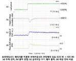
도 6 및 도 7은 부하변동에 대한 듀얼 엑티브 브릿지 컨버터의 응답을 나타낸다. 구체적으로, 도 6 및 도 7의 (a)는 부하 전력(Load power), (b)는 출력 전압(Output voltage), (c)는 슬라이딩 모드 제어 출력(Output of SMC(Sliding Mode Control)), (d)는 위상 천이 비율(Phase shift ratio)을 각각 나타낸다. 도 6 및 도 7에서, 부하는 125W에서 425W, 425W에서 125W로 각각 변화한다. 또한, 본 실험에서는 DC 버스 전압을 250V로 제어하고 있으며, 정격 전력을 700W로 제한하여 실험하였다. 여기에서는, 전부하 조건에서는 제어기의 성능을 확인하기 어려우므로 정격의 40% 정도인 300W의 부하 변동을 고려하였으며, 부하 변동시 DC 버스 전압은 2ms 이내로 수렴할 수 있다. 또한, 부하 증가시의 전압 변동은 4.5V 이하의 값을 가지며, 이는 DC 버스 전압의 1.8%에 해당할 수 있다. 또한, 부하 감소시 전압의 변동은 약 2V로서, 1% 이하의 값을 가짐을 확인할 수 있다.Figures 6 and 7 show the response of the dual active bridge converter to load variations. Specifically, FIGS. 6 and 7A show load power, FIG. 7B shows an output voltage, FIG. 7C shows a sliding mode control output (Output of SMC (Sliding Mode Control) (d) represents a phase shift ratio. In Figures 6 and 7, the load changes from 125W to 425W and from 425W to 125W, respectively. In this experiment, the DC bus voltage is controlled to 250V and the rated power is limited to 700W. Here, since it is difficult to confirm the performance of the controller under the full load condition, the load fluctuation of 300W which is about 40% of the rated value is considered, and the DC bus voltage can converge within 2ms when the load is changed. In addition, the voltage fluctuation when the load increases is 4.5 V or less, which may correspond to 1.8% of the DC bus voltage. In addition, it can be confirmed that the voltage variation when the load is reduced is about 2V, which is less than 1%.
도 8 및 도 9는 DC 버스 전압의 지령치가 변동할 경우의 전압제어 결과를 나타낸다. 구체적으로, 도 8 및 도 9의 (a)는 출력 전압(Output voltage), (b)는 슬라이딩 모드 제어 출력(Output of SMC), (c)는 위상 천이 비율(Phase shift ratio)을 각각 나타낸다. 도 8 및 도 9에서, 전압 지령은 250V에서 270V, 270V에서 250V로 각각 변화한다. 지령 전압이 증가하는 경우, 초기 제어기의 출력은 최대값을 가지며, 낮은 오버슛을 가지고 지령 전압에 수렴함을 확인할 수 있다. 또한, 지령 전압이 감소하는 경우에도, 빠른 수렴속도를 가짐을 확인할 수 있다.8 and 9 show voltage control results when the command value of the DC bus voltage fluctuates. Specifically, FIGS. 8 and 9A show the output voltage, FIG. 8B shows a sliding mode control output (Output of SMC), and FIG. 9C shows a phase shift ratio. 8 and 9, the voltage command changes from 250V to 270V and from 270V to 250V, respectively. When the command voltage increases, it can be confirmed that the output of the initial controller has a maximum value and converges to the command voltage with a low overshoot. In addition, it can be confirmed that even when the command voltage decreases, it has a fast convergence speed.
도 10은 부하변동조건에서 본 발명의 일 실시예에 따른 슬라이딩 모드 제어기의 성능을 검증하기 위해, PI제어기를 적용한 결과와 본 발명의 일 실시예에 따른 슬라이딩 모드 제어기를 적용한 결과를 비교한 파형을 나타낸다. 구체적으로, 도 10의 (a)는 부하가 125W에서 425W로 증가하는 경우의 파형을 나타내며, (b)는 부하가 425W에서 125W로 감소하는 경우의 파형을 나타낸다. 여기에서, PI 제어기는 대역폭이 높아짐에 따라 응답 속도가 빨라지나, 정상 상태에서의 진동이 여전히 존재함을 확인할 수 있다. 그러나, 본 발명의 일 실시예에 따른 슬라이딩 모드 제어기를 적용하는 경우, PI제어기보다 수렴 속도가 빠르며, 정상상태에서의 진동도 없음을 확인할 수 있다.10 is a graph illustrating a comparison result between a result of applying a PI controller and a result of applying a sliding mode controller according to an embodiment of the present invention in order to verify the performance of the sliding mode controller according to an embodiment of the present invention under a load fluctuation condition . Specifically, FIG. 10A shows the waveform when the load increases from 125W to 425W, and FIG. 10B shows the waveform when the load decreases from 425W to 125W. Here, the PI controller shows that although the response speed increases as the bandwidth increases, the vibration in the steady state still exists. However, when the sliding mode controller according to an embodiment of the present invention is applied, it can be confirmed that the convergence speed is faster than that of the PI controller and no vibration occurs in the steady state.
도 11은 DC 버스 전압의 지령치를 변동하였을 경우의 비교 결과를 나타낸다. 구체적으로, 도 10의 (a)는 DC 버스 전압의 지령치가 250V에서 270V로 변동하는 경우의 파형을 나타내며, (b)는 DC 버스 전압의 지령치가 270V에서 250V로 변동하는 경우의 파형을 나타낸다. 여기에서, 본 발명의 일 실시예에 따른 슬라이딩 모드 제어기를 적용하는 경우, 오버슛 및 언더슛 전압이 감쇠됨을 확인할 수 있으며, PI 제어기보다 빠르게 지령전압에 수렴함을 확인할 수 있다.11 shows a comparison result when the command value of the DC bus voltage is changed. Specifically, FIG. 10A shows a waveform when the DC bus voltage command value fluctuates from 250V to 270V, and FIG. 10B shows a waveform when the command value of the DC bus voltage fluctuates from 270V to 250V. Here, when the sliding mode controller according to an embodiment of the present invention is applied, it can be confirmed that the overshoot and undershoot voltage are attenuated, and it can be confirmed that the command voltage converges faster than the PI controller.
도 12는 듀얼 엑티브 브릿지 컨버터가 배터리측의 인덕터 전류를 제어하는 경우의 실험 결과를 나타낸다. 구체적으로, 도 12의 (a)는 충전 전류(Charging current), (b)는 위상 천이 비율(Phase shift ratio), (c)는 슬라이딩 변수를 나타낸다. 이때, 배터리 충전시 오버슛과 같은 임펄스 형태의 전류는 배터리의 수명에 악영향을 미칠 수 있으며, 배터리의 상태를 관리하는데 있어 오차를 발생시키는 원인이 될 수 있다. 따라서, 전류제어를 위해 오버슛 및 정상상태가 없는 조건을 만족하는 제어이득을 선정하였다. 여기에서, 지령 전류(충전 전류)는 0A와 7A로 변동하며, 이때 제어기의 출력인 위상천이 비율을 나타낸다. 이때, 전류는 지령치를 잘 추종하고 있으며, 슬라이딩 변수는 0으로 수렴함을 확인할 수 있다. 또한 이때, 오버슛 및 언더슛이 없는 결과를 위해, 제어기의 초기 응답이 느려 보이나, 10ms 내에 지령 전류에 도달함을 확인할 수 있다.12 shows experimental results when the dual active bridge converter controls the inductor current on the battery side. Specifically, FIG. 12A shows a charging current, FIG. 12B shows a phase shift ratio, and FIG. At this time, an impulse-type current such as an overshoot when charging the battery may adversely affect the life of the battery and cause an error in managing the state of the battery. Therefore, the control gain satisfying the conditions of no overshoot and steady state is selected for current control. Here, the command current (charge current) fluctuates between 0A and 7A and represents the phase shift ratio which is the output of the controller at this time. At this time, the current follows the set value well, and the sliding variable converges to zero. Also, at this time, it can be confirmed that the initial response of the controller seems to be slow but reaches the command current within 10 ms for the result that there is no overshoot and undershoot.
도 13은 본 발명의 일 실시예에 따른 슬라이딩 모드 제어기의 성능을 검증하기 위해, PI 전류제어를 적용한 결과와 본 발명의 일 실시예에 따른 슬라이딩 모드 제어기를 적용한 결과의 비교를 나타낸다. 구체적으로, 도 13의 (a)는 지령 전류(충전 전류)가 0A에서 7A로 변동하는 경우의 파형을 나타내며, (b)는 지령 전류가 7A에서 0A로 변동하는 경우의 파형을 나타낸다. 이때, 도 13에서 나타나는 PI1에 대한 결과는 오버슛 및 언더슛이 없는 제어이득을 선정한 결과를 나타낸다. 여기에서, 본 발명의 일 실시예에 따른 슬라이딩 모드 제어기와 비교하였을 때, 그 응답이 느림을 확인할 수 있다. 또한, PI 제어기의 응답 속도를 더 높인 PI2의 경우에는, 응답 속도는 빨라졌으나 오버슛 및 언더슛이 발생함을 확인할 수 있다.FIG. 13 shows a comparison between results of applying the PI current control and results of applying the sliding mode controller according to an embodiment of the present invention to verify the performance of the sliding mode controller according to an embodiment of the present invention. Specifically, FIG. 13A shows a waveform when the command current (charge current) varies from 0A to 7A, and FIG. 13B shows a waveform when the command current varies from 7A to 0A. At this time, the result for PI1 shown in FIG. 13 shows the result of selecting the control gain without overshoot and undershoot. Here, it can be confirmed that the response is slow compared with the sliding mode controller according to the embodiment of the present invention. Also, in the case of PI2 , which has a higher response speed of the PI controller, it can be confirmed that overshoot and undershoot occur although the response speed is increased.
본 발명의 일 실시예들에 따르면, 외란항을 포함하는 상태방정식 및 적분항을 포함하는 슬라이딩 평면 함수로부터 등가 입력을 계산하여 듀얼 엑티브 브릿지 컨버터를 제어함으로써, 듀얼 엑티브 브릿지 컨버터의 동특성을 향상시킬 수 있다. 또한, 본 발명의 일 실시예들에 따르면, 계산된 등가 입력을 이용하여 듀얼 엑티브 브릿지 컨버터를 제어함으로써 듀얼 엑티브 브릿지 컨버터가 외란에 강인하도록 할 수 있으며, 듀얼 엑티브 브릿지 컨버터의 정상상태 오차가 0으로 수렴하도록 할 수 있다.According to one embodiment of the present invention, dynamic characteristics of a dual active bridge converter can be improved by controlling the dual active bridge converter by calculating an equivalent input from a sliding plane function including a state equation including a disturbance term and an integral term have. Also, according to one embodiment of the present invention, the dual active bridge converter can be made robust to disturbance by controlling the dual active bridge converter using the calculated equivalent input, and the steady state error of the dual active bridge converter is set to zero Convergence.
이상에서 대표적인 실시예를 통하여 본 발명에 대하여 상세하게 설명하였으나, 본 발명이 속하는 기술분야에서 통상의 지식을 가진 자는 전술한 실시예에 대하여 본 발명의 범주에서 벗어나지 않는 한도 내에서 다양한 변형이 가능함을 이해할 것이다. 그러므로 본 발명의 권리범위는 설명된 실시예에 국한되어 정해져서는 안 되며, 후술하는 특허청구범위뿐만 아니라 이 특허청구범위와 균등한 것들에 의해 정해져야 한다.While the present invention has been particularly shown and described with reference to exemplary embodiments thereof, it is to be understood that the invention is not limited to the disclosed embodiments, but, on the contrary, I will understand. Therefore, the scope of the present invention should not be limited to the above-described embodiments, but should be determined by equivalents to the appended claims, as well as the appended claims.
100: 슬라이딩 모드 제어기
110: 변환부
120: 함수 획득부
130: 제어부100: Sliding mode controller
110:
120: function acquisition unit
130:
Claims (4)
Translated fromKorean상기 전압과 지령전압 간의 차 또는 상기 전류와 지령전류 간의 차를 오차로 설정하고, 상기 오차, 상기 오차의 적분항 및 상기 오차의 이중 적분항을 포함하는 슬라이딩 평면 함수를 획득하는 함수 획득부; 및
상기 상태 방정식을 이용하여 상기 슬라이딩 평면 함수의 미분값이 0이 되게 하는 등가 입력(ueq)를 계산하고, 상기 등가 입력(ueq)을 이용하여 상기 듀얼 엑티브 브릿지 컨버터를 제어하는 제어부를 포함하는, 슬라이딩 모드 제어기.
A voltage (vb ) of the battery in the system including a dual active bridge (DAB) converter, a battery connected to the dual active bridge converter, and an inductor Lf disposed between the converter and the battery, (Ib ) into a state equation including a disturbance term; and a controller for converting the current into a state equation including a disturbance term.
A function obtaining unit for setting a difference between the voltage and the command voltage or a difference between the current and the command current as an error and obtaining a sliding plane function including the error, the integral term of the error and the double integral term of the error; And
And a control unit for calculating an equivalent input ueq to make the differential value of the sliding plane function 0 using the state equation and controlling the dual active bridge converter using the equivalent input ueq , A sliding mode controller.
상기 외란항은, 상기 배터리의 전압(vb)에 대한 방정식의 경우 상기 듀얼 엑티브 브릿지 컨버터의 배터리측 전류(is)에 관한 항이며, 상기 배터리에 흐르는 전류(ib)에 대한 방정식의 경우 상기 배터리의 전압(vb)에 관한 항인, 슬라이딩 모드 제어기.
The method according to claim 1,
The disturbance term is a term relating to the battery side current (is ) of the dual active bridge converter in the case of the equation for the voltage (vb ) of the battery, and in the case of the equation for the current (ib ) flowing in the battery (Vb ) of said battery.
상기 상태 방정식은, 하기 수학식으로 표시되는, 슬라이딩 모드 제어기.

(여기서, x는 상기 배터리의 전압(vb) 또는 상기 배터리에 흐르는 전류(ib), f는 x에 관한 항, g는 상기 듀얼 엑티브 브릿지 컨버터의 출력측 전압 (vdc)에 관한 항, u는 제어 입력에 관한 항, E는 외란항)
The method according to claim 1,
Wherein the state equation is expressed by the following equation.
Where x is the voltage of the battery (vb ) or current flowing through the battery (ib ), f is a term relating to x, g is a term relating to the output side voltage (vdc ) of the dual active bridge converter, u Is a term relating to a control input, and E is a disturbance term)
상기 슬라이딩 평면 함수는, 하기 수학식으로 표시되는, 슬라이딩 모드 제어기.

(여기서, e는 오차(x-xd), x는 상기 배터리의 전압(vb) 또는 상기 배터리에 흐르는 전류(ib), xd는 지령전압 또는 지령전류, k1, k2는 양의 값을 가지는 제어 이득)
The method according to claim 1,
Wherein the sliding plane function is expressed by the following equation.
(Where, e is the error (xxd), x is the voltage of the battery (vb) or the current flowing through the battery (ib), xd is a command voltage or command current, k1, k2 is a positive value of / RTI >
Priority Applications (1)
| Application Number | Priority Date | Filing Date | Title |
|---|---|---|---|
| KR1020160157684AKR101848903B1 (en) | 2016-11-24 | 2016-11-24 | Sliding mode controller for dual active bridge converter |
Applications Claiming Priority (1)
| Application Number | Priority Date | Filing Date | Title |
|---|---|---|---|
| KR1020160157684AKR101848903B1 (en) | 2016-11-24 | 2016-11-24 | Sliding mode controller for dual active bridge converter |
Publications (1)
| Publication Number | Publication Date |
|---|---|
| KR101848903B1true KR101848903B1 (en) | 2018-04-13 |
Family
ID=61974056
Family Applications (1)
| Application Number | Title | Priority Date | Filing Date |
|---|---|---|---|
| KR1020160157684AActiveKR101848903B1 (en) | 2016-11-24 | 2016-11-24 | Sliding mode controller for dual active bridge converter |
Country Status (1)
| Country | Link |
|---|---|
| KR (1) | KR101848903B1 (en) |
Cited By (3)
| Publication number | Priority date | Publication date | Assignee | Title |
|---|---|---|---|---|
| CN111404374A (en)* | 2020-03-26 | 2020-07-10 | 河南科技大学 | A control method of bidirectional DC-DC converter optimized by genetic algorithm |
| CN111478592A (en)* | 2020-05-09 | 2020-07-31 | 哈尔滨理工大学 | Sliding mode control method of double-active full-bridge DC-DC converter |
| CN118381337A (en)* | 2024-05-21 | 2024-07-23 | 扬州大学 | A preset time feedback controller, control system and control method of a dual active bridge circuit |
Citations (2)
| Publication number | Priority date | Publication date | Assignee | Title |
|---|---|---|---|---|
| JPH0799785A (en)* | 1992-07-22 | 1995-04-11 | Ansaldo Un Azienda Finmecc Spa | Saturation-preventing circuit device of transformer in dc/ac converter with feedback control inverter |
| JP2010268584A (en)* | 2009-05-13 | 2010-11-25 | Shindengen Electric Mfg Co Ltd | Inverter |
- 2016
- 2016-11-24KRKR1020160157684Apatent/KR101848903B1/enactiveActive
Patent Citations (2)
| Publication number | Priority date | Publication date | Assignee | Title |
|---|---|---|---|---|
| JPH0799785A (en)* | 1992-07-22 | 1995-04-11 | Ansaldo Un Azienda Finmecc Spa | Saturation-preventing circuit device of transformer in dc/ac converter with feedback control inverter |
| JP2010268584A (en)* | 2009-05-13 | 2010-11-25 | Shindengen Electric Mfg Co Ltd | Inverter |
Non-Patent Citations (4)
| Title |
|---|
| Energy Conversion Congress and Exposition (ECCE), 2010 IEEE* |
| IEEE TRANSACTIONS ON POWER ELECTRONICS, VOL. 23, NO. 2* |
| Ik-Chan Choi et al. "Robust Voltage Control of Dual Active Bridge DC-DC Converters using Sliding Mode Control". IEEE. (발표일 : 2016.05.26.)* |
| S. Talbi et al. "Control of a Bidirectional Dual Active Bridge Converter for Charge and Discharge of a Li-Ion Battery". IEEE. 2009.* |
Cited By (4)
| Publication number | Priority date | Publication date | Assignee | Title |
|---|---|---|---|---|
| CN111404374A (en)* | 2020-03-26 | 2020-07-10 | 河南科技大学 | A control method of bidirectional DC-DC converter optimized by genetic algorithm |
| CN111404374B (en)* | 2020-03-26 | 2021-04-30 | 河南科技大学 | Control Method of Bidirectional DC-DC Converter Optimized by Genetic Algorithm |
| CN111478592A (en)* | 2020-05-09 | 2020-07-31 | 哈尔滨理工大学 | Sliding mode control method of double-active full-bridge DC-DC converter |
| CN118381337A (en)* | 2024-05-21 | 2024-07-23 | 扬州大学 | A preset time feedback controller, control system and control method of a dual active bridge circuit |
Similar Documents
| Publication | Publication Date | Title |
|---|---|---|
| JP4762134B2 (en) | Resonant switching power supply | |
| US9413270B2 (en) | Single-phase three-wire power control system and power control method therefor | |
| CN110168883B (en) | LLC converter controlled by PIR and method for controlling LLC converter | |
| JP5807658B2 (en) | Power conversion device and power conversion method | |
| KR20140113521A (en) | Methods and systems for control of dc-dc converters | |
| Kapat et al. | Near-null response to large-signal transients in an augmented buck converter: A geometric approach | |
| KR101848903B1 (en) | Sliding mode controller for dual active bridge converter | |
| Jeung et al. | Robust voltage control of dual active bridge DC-DC converters using sliding mode control | |
| WO2022177818A1 (en) | Dual active bridge optimization with triple phase shift and variable inductor | |
| US12068693B2 (en) | Digital nonlinear transformation for voltage-mode control of a power converter | |
| Pidaparthy et al. | Stabilizing effects of load subsystem in multistage dc-to-dc power conversion systems | |
| JP6398773B2 (en) | Control circuit and switching power supply | |
| Shaw et al. | Mixed-sensitivity based robust H∞ controller design for high-gain boost converter | |
| EP3091650A1 (en) | Improving the accuracy of a volt-second clamp in an isolated dc/dc converter | |
| CN104682704A (en) | Feedback compensation circuit based on variable zero and switching power supply applying same | |
| CN112421950A (en) | Control Method of Boost Converter Based on Disturbance Observer and Integral Sliding Mode Control | |
| Zou et al. | Design, analyses and validation of sliding mode control for a dab dc-dc converter | |
| Nabeshima et al. | Hysteretic PWM control method for all types of DC-to-DC converters | |
| TWI406486B (en) | Systems and methods of primary-side sensing and regulation for flyback power converter with high stability | |
| Viet et al. | Feedback Linearization Control and Current Control Mode for Boost Converter | |
| JP6016054B2 (en) | DC-DC converter | |
| Reis et al. | Filtered smith predictor applied to a boost converter for minimizing the effect of non-minimal phase and rejection of disturbances | |
| Cheng et al. | An Overview of Stability Improvement Methods for Wide-Operation-Range Flyback Converter with Variable Frequency Peak-Current-Mode Control | |
| KR102777626B1 (en) | Apparatus for balancing flying capacitor of dc-dc converter, and control method thereof | |
| Andersen et al. | Digital peak current mode control with adaptive slope compensation for DC-DC converters |
Legal Events
| Date | Code | Title | Description |
|---|---|---|---|
| PA0109 | Patent application | Patent event code:PA01091R01D Comment text:Patent Application Patent event date:20161124 | |
| PA0201 | Request for examination | ||
| E701 | Decision to grant or registration of patent right | ||
| PE0701 | Decision of registration | Patent event code:PE07011S01D Comment text:Decision to Grant Registration Patent event date:20180402 | |
| GRNT | Written decision to grant | ||
| PR0701 | Registration of establishment | Comment text:Registration of Establishment Patent event date:20180409 Patent event code:PR07011E01D | |
| PR1002 | Payment of registration fee | Payment date:20180409 End annual number:3 Start annual number:1 | |
| PG1601 | Publication of registration | ||
| PR1001 | Payment of annual fee | Payment date:20210402 Start annual number:4 End annual number:4 | |
| PR1001 | Payment of annual fee | Payment date:20220401 Start annual number:5 End annual number:5 | |
| PR1001 | Payment of annual fee | Payment date:20240327 Start annual number:7 End annual number:7 |