KR101847675B1 - Method and device for stereo base extension of stereoscopic images and image sequences - Google Patents
Method and device for stereo base extension of stereoscopic images and image sequencesDownload PDFInfo
- Publication number
- KR101847675B1 KR101847675B1KR1020137021439AKR20137021439AKR101847675B1KR 101847675 B1KR101847675 B1KR 101847675B1KR 1020137021439 AKR1020137021439 AKR 1020137021439AKR 20137021439 AKR20137021439 AKR 20137021439AKR 101847675 B1KR101847675 B1KR 101847675B1
- Authority
- KR
- South Korea
- Prior art keywords
- camera
- point
- viewpoint
- pixel
- leftmost
- Prior art date
- Legal status (The legal status is an assumption and is not a legal conclusion. Google has not performed a legal analysis and makes no representation as to the accuracy of the status listed.)
- Active
Links
- 238000000034methodMethods0.000titleclaimsabstractdescription46
- 230000015572biosynthetic processEffects0.000claimsabstractdescription11
- 238000003786synthesis reactionMethods0.000claimsabstractdescription11
- 238000012545processingMethods0.000claimsabstractdescription9
- 239000002131composite materialSubstances0.000claimsdescription8
- 239000000203mixtureSubstances0.000claims1
- 230000000873masking effectEffects0.000abstractdescription52
- 230000000007visual effectEffects0.000abstractdescription37
- 230000008447perceptionEffects0.000abstractdescription28
- 238000004364calculation methodMethods0.000abstractdescription5
- 230000006872improvementEffects0.000abstractdescription5
- 238000005259measurementMethods0.000abstractdescription2
- 238000013329compoundingMethods0.000abstract2
- 230000008569processEffects0.000description13
- 238000010586diagramMethods0.000description9
- 230000003287optical effectEffects0.000description5
- 210000001525retinaAnatomy0.000description5
- 239000011521glassSubstances0.000description4
- 238000013459approachMethods0.000description3
- 238000006243chemical reactionMethods0.000description2
- 238000007796conventional methodMethods0.000description2
- 230000000694effectsEffects0.000description2
- 238000009499grossingMethods0.000description2
- 230000009471actionEffects0.000description1
- 230000006978adaptationEffects0.000description1
- 230000008859changeEffects0.000description1
- 238000012937correctionMethods0.000description1
- 230000006378damageEffects0.000description1
- 238000013461designMethods0.000description1
- 230000008030eliminationEffects0.000description1
- 238000003379elimination reactionMethods0.000description1
- 230000006870functionEffects0.000description1
- 238000004519manufacturing processMethods0.000description1
- 239000011159matrix materialSubstances0.000description1
- 210000000056organAnatomy0.000description1
- 238000003672processing methodMethods0.000description1
- 230000009467reductionEffects0.000description1
- 229940097988rightstepDrugs0.000description1
- 238000003892spreadingMethods0.000description1
- 238000003860storageMethods0.000description1
- 230000001360synchronised effectEffects0.000description1
- 238000011426transformation methodMethods0.000description1
- XLYOFNOQVPJJNP-UHFFFAOYSA-NwaterSubstancesOXLYOFNOQVPJJNP-UHFFFAOYSA-N0.000description1
Images


Classifications
- H—ELECTRICITY
- H04—ELECTRIC COMMUNICATION TECHNIQUE
- H04N—PICTORIAL COMMUNICATION, e.g. TELEVISION
- H04N13/00—Stereoscopic video systems; Multi-view video systems; Details thereof
- H04N13/10—Processing, recording or transmission of stereoscopic or multi-view image signals
- H04N13/106—Processing image signals
- H04N13/122—Improving the 3D impression of stereoscopic images by modifying image signal contents, e.g. by filtering or adding monoscopic depth cues
- H—ELECTRICITY
- H04—ELECTRIC COMMUNICATION TECHNIQUE
- H04N—PICTORIAL COMMUNICATION, e.g. TELEVISION
- H04N13/00—Stereoscopic video systems; Multi-view video systems; Details thereof
- H04N13/10—Processing, recording or transmission of stereoscopic or multi-view image signals
- H04N13/106—Processing image signals
- H04N13/111—Transformation of image signals corresponding to virtual viewpoints, e.g. spatial image interpolation
- H—ELECTRICITY
- H04—ELECTRIC COMMUNICATION TECHNIQUE
- H04N—PICTORIAL COMMUNICATION, e.g. TELEVISION
- H04N13/00—Stereoscopic video systems; Multi-view video systems; Details thereof
- H04N13/20—Image signal generators
- H04N13/271—Image signal generators wherein the generated image signals comprise depth maps or disparity maps
- H—ELECTRICITY
- H04—ELECTRIC COMMUNICATION TECHNIQUE
- H04N—PICTORIAL COMMUNICATION, e.g. TELEVISION
- H04N13/00—Stereoscopic video systems; Multi-view video systems; Details thereof
- H04N2013/0074—Stereoscopic image analysis
- H04N2013/0081—Depth or disparity estimation from stereoscopic image signals
Landscapes
- Engineering & Computer Science (AREA)
- Multimedia (AREA)
- Signal Processing (AREA)
- Testing, Inspecting, Measuring Of Stereoscopic Televisions And Televisions (AREA)
- Image Processing (AREA)
- Stereoscopic And Panoramic Photography (AREA)
Abstract
Translated fromKoreanDescription
Translated fromKorean본 발명은 입체영상과 영상시퀀스(image sequences)의 깊이지각(depth impression)을 개선하기 위한 방법 및 장치에 관한 것이다. 이와 같은 개선은 스테레오 카메라로 측정할 때 또는 입체 디스플레이 장치내에서 이루어질 수 있다.The present invention relates to a method and apparatus for improving depth impression of stereoscopic images and image sequences. Such improvements can be made when measuring with a stereo camera or in a stereoscopic display device.
1931년에 이미 뤼셔(Luescher) 참고 문헌 [1]에 해당하는 자신의 논문에서 스테레오스코피(stereoscopy)의 기본 규칙들을 정했다. 제1 규칙(a)은 입체영상의 좌우측 부분 이미지가 동일한 시각 차이를 가져야만 한다는 것인데, 다시 말하자면 스테레오 간격이 65mm 범위 안에 놓여 있어야만 한다는 것이다.In 1931, he set out the basic rules of stereoscopy in his paper, which corresponds to Luescher reference [1]. The first rule (a) is that the left and right partial images of the stereoscopic image must have the same visual difference, that is, the stereo spacing must lie within the 65 mm range.
기술적이거나 설계상의 여러 이유로 상기 규칙은 스테레오 사진기나 비디오-리코더에서 위배되는 경우가 있다. 이 경우, 본 발명에 의한 스테레오 간격 확대에 의한 적응이 이루어질 수 있다.For reasons of technical or design reasons, the above rules may violate stereophotos or video-recorders. In this case, adaptation can be made by enlarging the stereo interval according to the present invention.
측정시 이런 렌즈 간격이 지켜지면, 이 렌즈 간격은 3D-안경을 사용하거나 무안경 싱글뷰어 디스플레이 장치에서 우수한 깊이지각을 일으킨다.If such a lens spacing is observed during the measurement, then this lens spacing will result in an excellent depth perception using 3D-glasses or a non-spectacles single-viewer display.
그러나, 무안경 멀티뷰어 디스플레이 장치에서는 일반적으로 다수의 중간시점 영상들이 생기고, 이때문에 깊이지각이 떨어진다. 이와 같은 현상은 뤼셔에 의해 세워진 기본 규칙, 즉 "볼 때는 측정할 때와 같은 시각(스테레오 간격)이 유지되어야 한다"라는 기본 규칙에 모순된다. 이 경우에도 본 발명에 의한 스테레오 간격-확대는 중요한 개선을 도모하여, 현실과 같은 깊이지각을 일으킬 수 있다.However, in a spectacle-free multi-viewer display device, a number of mid-view images are generally produced and therefore the depth perception is reduced. Such a phenomenon contradicts the basic rule established by rusher, ie, "the time (stereo spacing) must be maintained as measured when viewed." Even in this case, the stereo interval-enlargement according to the present invention makes significant improvement, and can cause a depth perception like reality.
이하, 무안경 멀티뷰어 디스플레이 장치를 위한 스테레오 간격-확대를 먼저 설명한 다음 입체 측정장치로 그 예를 확장하겠지만, 반드시 이에 한정되는 것도 아니다. 두 가지 경우의 기본 원리들이 동일하기 때문에, 이런 설명도 가능하다.Hereinafter, the stereo interval-magnification for a spectaclesless multi-viewer display device will be described first, and then an example thereof will be expanded by a stereoscopic measuring device. However, the present invention is not limited thereto. Since the basic principles of the two cases are the same, this explanation is possible.
3D-안경의 지원을 받는 디스플레이 장치에서는, 일반적으로 두 개의 렌즈를 갖는 스테레오 카메라에 의해 측정된 입체영상이 각각 뷰어의 좌우측 눈에 제공된다. 여러 뷰어가 3D-안경을 착용하면, 모든 뷰어가 동시에 하나의 우수한 3D-인상을 지각할 수 있다. 이 경우, 감지된 눈의 간격이 두개 카메라 렌즈의 간격과 정확하게 일치한다. 일반적으로 이 간격은 자연스러운 공간감을 느끼기 위해 대략 65mm 범위내에 있다.In a display device supported by 3D-glasses, stereoscopic images measured by a stereo camera, which generally has two lenses, are provided to the left and right eyes of the viewer, respectively. When multiple viewers wear 3D-glasses, all viewers can perceive one good 3D-impression at the same time. In this case, the interval of the detected eyes exactly coincides with the interval of the two camera lenses. Generally, this gap is within the range of about 65 mm to feel a natural spatial feeling.
무안경 멀티뷰어 디스플레이에서는 디스플레이 앞에 정확하게 하나의 최적 관찰 위치가 존재하며, 이 관찰위치에서 한명의 뷰어만 최고의 깊이지각을 느낄 수 있다. 몇몇 무안경 싱글뷰어 디스플레이는 소위 헤드-트랙킹-시스템으로 뷰어의 눈을 추적해 각개 뷰어에 적응하도록 한다.In a spectacles multi-viewer display, there is exactly one optimal viewing position in front of the display, where only one viewer can experience the best depth perception. Some non-eyeglass single-view displays track the eyes of the viewer with so-called head-tracking systems to adapt to each viewer.
참고 문헌 [2]에는, 다수의 뷰어가 동시에 관찰되고 추적될 수 있는 시스템이 처음으로 기재되어 있다.Reference [2] describes a system in which a plurality of viewers can be simultaneously observed and tracked.
모든 시스템에서의 공통점은, 뷰어가 최상의 깊이지각을 느끼는데 필요한 카메라 시점은 2개면 된다.The commonality in all systems is that the viewer needs two camera points to get the best depth perception.
그러나, 이런 방식은 거실이나 공공시설에서 사용하기에는 비실용적이다. 가급적 많은 여러명의 뷰어가 동시에 운동성의 제한 없이 최고의 깊이지각을 느껴야만 한다.However, this approach is impractical for use in living rooms or public facilities. As many viewers as possible should feel the best depth perception at the same time without limit of mobility.
공지의 무안경 멀티뷰어 디스플레이 장치에서 느낄 수 있는 이런 최고의 깊이지각은, 측정된 카메라 시점들 사이에 소정의 중간시점들이 합성에 의해 생성되고 이런 중간시점들을 디스플레이 장치 앞에서 일단의 비주얼존을 생성하는데 사용하여 얻을 수 있다. 각각의 비주얼존에서 하나나 다수의 뷰어가 자유롭게 움직일 수 있고 하나의 깊이지각을 느낄 수 있다.This best depth perception that can be felt in a known eyeglass multi-viewer display device is such that certain intermediate viewpoints between measured camera views are created by compositing and used to generate a set of visual zones in front of the display device . In each visual zone one or more viewers can move freely and feel a depth perception.
비주얼존은 사용된 광학 시스템에 따라서 소정의 폭을 갖는다. 뷰어가 비주얼존의 좌측 가장자리에 있으면 뷰어의 좌측눈이 좌측 카메라 시점을 지각하고, 뷰어가 비주얼존의 우측 가장자리에 있으면 뷰어의 우측눈이 우측 카메라 시점을 지각한다. 일반적으로 비주얼존의 폭은 300~600 mm 정도이다. 뷰어가 한쪽 비주얼존에서 다른 비주얼존으로 이동하면, 짧은 구간에서 선명하지 않은 입체영상이 생성된다.The visual zone has a predetermined width depending on the optical system used. If the viewer is at the left edge of the visual zone, the left eye of the viewer perceives the left camera view, and if the viewer is at the right edge of the visual zone, the right eye of the viewer perceives the right camera view. Typically, the width of the visual zone is about 300 to 600 mm. When the viewer moves from one visual zone to another, a sharp image is produced in a short interval.
그러나, 비주얼존 간격(대개 65mm)이 눈간격보다 훨씬 넓기 때문에, 좌측 가장자리의 우측 눈은 우측 카메라 시점보다는 좌측 카메라 시점에서 훨씬 더 조밀한 시점을 느낄 것이다. 이런 사실로 감지된 눈 간격이 카메라 간격, 즉 두개의 카메라렌즈의 간격보다 훨씬 더 작다는 것을 알 수 있다. 결과적으로, 무안경 멀티뷰어 디스플레이 장치에서는 깊이지각이 크게 감소한다. 이런 깊이지각의 감소율은 비주얼존의 폭이 넓을수록 크다. 한편, 뷰어의 운동 자유도를 최대화하려면 비주얼존의 폭이 가급적 넓어야 한다. However, since the visual zone spacing (typically 65 mm) is much wider than the eye spacing, the right eye of the left edge will feel a much denser point at the left camera view than the right camera viewpoint. It can be seen that the eye interval detected by this fact is much smaller than the camera interval, that is, the distance between the two camera lenses. As a result, the depth perception is greatly reduced in a spectacle-free multi-viewer display device. The decrease rate of the depth perception is larger as the width of the visual zone is larger. On the other hand, in order to maximize the freedom of movement of the viewer, the width of the visual zone should be as wide as possible.
깊이지각의 감소는 전술한 디스플레이 장치의 주요 단점이고, 본 발명의 방법에 의해 경감되어야 하고, 경우에 따라서는 완전히 없어져야 한다.The reduction in depth perception is a major drawback of the display device described above, and should be mitigated by the method of the present invention and, in some cases, eliminated altogether.
이런 단점의 제거는, 카메라 렌즈의 주시 방향이 측정된 가장 좌측 및 가장 우측 카메라 렌즈의 좌측 및 우측에 있고 특허 청구항 1에 기재되어 있는 바와 같은 '시각적인 시점'의 발생에 의해서 달성된다. 이런 시각적인 시점을 이하 스테레오 간격-확장이라 하는데, 이는 가장 좌측에 있는 카메라 렌즈와 가장 우측에 있는 카메라 렌즈 사이의 연결 선이 스테레오 간격이고, 발생된 시각적인 시점이 측정된 스테레오 간격의 연장부에 있기 때문이다.This elimination of the disadvantages is achieved by the occurrence of a " visual point of view " as in
또, 본 발명은 적어도 하나의 프로세서와 메모리를 포함한 본 발명에 따른 방법을 실시하는 장치에 관한 것이기도 하다.The invention also relates to an apparatus for implementing a method according to the present invention comprising at least one processor and a memory.
스테레오 간격-확장은 지금까지 음향분야에서만 기술되었다. 이런 음향분야에는 관련 문헌이 널리 공지되어 있지만, 이들 문헌을 본 발명에서는 인용하지 않는다.Stereo interval - expansion has been described so far only in the sound field. Related literature is well known in such acoustical field, but these documents are not quoted in the present invention.
참고 문헌 [3]에는, 제공된 2D-이미지 및 깊이지도(depth map)로부터 출발하여 다수의 시점이 제공된 2D-이미지의 좌우측에서 생성되는 방법이 기술되어 있다. 이 문헌에 기술된 방식에 따르면, 2D-이미지는 깊이지도에 따라 변형된다. 그러나, 이 방식에서는 시각적으로 정확한 시점들은 나타날 수 없는데, 이는 좌우측 마스킹에 대한 정보가 없기 때문이다. 본 발명에 따른 방법을 위해서는 반드시 두개 이상의 시점이 제공된 입체영상이 필요하다. 이런 상황에서만 다양한 합성시점에 시각적으로 정확하게 마스킹을 실현할 수 있다.Reference [3] describes a method starting from a provided 2D-image and a depth map and being generated on the right and left of a 2D-image provided with a plurality of viewpoints. According to the method described in this document, the 2D-image is transformed according to the depth map. However, visually accurate views can not be shown in this manner because there is no information about left and right masking. The method according to the present invention requires a stereoscopic image provided with two or more viewpoints. Only in such a situation, it is possible to visually correct masking at various synthesis points.
한편, 좌우측 카메라 시점들 사이의 중간시점들을 생성하는 다수의 방법이 공지되어 있다. 본 발명은 참고문헌 [4]나 [5]를 참조한다.On the other hand, a number of methods are known for creating intermediate views between the left and right camera views. The present invention refers to references [4] and [5].
이런 모든 방법은 본 발명과는 관련이 없는데, 이는 이들 방법이 스테레오 간격 외부에서 추가 시점들을 생성하는데 있지 않고 바람직한 방식으로 변형될 수도 없기 때문이다.All of these methods are irrelevant to the present invention because these methods do not create additional points outside of the stereo spacing and can not be modified in a desirable manner.
또, 예컨대 참고 문헌 [7]에 기술되어 있는 바와 같은 외삽 변형 방법들도 전술한 문제해결에 이용될 수 없는데, 이는 이런 방법들이 장면의 기하학적인 특성들을 시각적으로 정확하게 유지하고 보완할 수 없기 때문이다.Extrapolative transformation methods as described, for example, in reference [7] can not be used for the above-mentioned problems because they can not visually and accurately maintain the geometric properties of the scene .
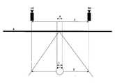
도 1은 지금까지 공지된 멀티뷰어 디스플레이 장치의 경우에 비주얼존에서 스테레오 카메라의 스테레오 간격의 변환을 도시한 개략도이다.
LC: 좌측 카메라 시점
RC: 우측 카메라 시점
1: 뷰어의 눈 간격
2: 뷰어 위치에서의 비주얼존 폭
3: 스테레오 카메라의 렌즈 간격
4: 감지된 눈 간격
5: 디스플레이 장치
도 2는 비주얼존에서 스테레오 간격-확장에 의한 스테레오 카메라의 확장된 스테레오 간격의 변환을 도시한 개략도이다.
LC: 좌측 실제 카메라 시점
RC: 우측 실제 카메라 시점
LE: 좌측 합성 카메라 시점
RE: 우측 합성 카메라 시점
1: 뷰어의 눈 간격
2: 뷰어 위치에서의 비주얼존 폭
3: 실제 스테레오 카메라의 렌즈 간격
4: 감지된 눈 간격
5: 디스플레이 장치
도 3은 세 개의 물체를 갖는 장면이 스테레오 카메라의 우측 렌즈에 의해서 측정된 개략도이다.
RR: 우측 망막(retina)
O1: 물체 1
O2: 물체 2
O3: 물체 3
PO1: O1의 물체 세그먼트의 투영
PO2: O2의 물체 세그먼트의 투영
PO3: O3의 물체 세그먼트의 투영
도 4는 스테레오 카메라의 좌측 렌즈에 의해서 측정된, 도 3에서와 동일한 장면을 도시한 개략도이다.
LR: 좌측 망막
O1: 물체 1
O2: 물체 2
O3: 물체 3
PO1: O1의 물체 세그먼트의 투영
PO2: O2의 물체 세그먼트의 투영
PO3: O3의 물체 세그먼트의 투영
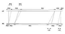
도 5는 도 4에 도시된 좌측 이미지 LC 및 도 3에 도시된 우측 이미지 RC의 시차(disparity)를 도시한 개략도이다.
LC: 좌측 카메라 시점
RC: 우측 카메라 시점
PO1: O1의 물체 세그먼트의 투영
PO2: O2의 물체 세그먼트의 투영
PO3: O3의 물체 세그먼트의 투영
RV2: 물체 2의 우측 마스킹
RV3: 물체 3의 우측 마스킹
LV2: 물체 2의 좌측 마스킹
LV3: 물체 3의 좌측 마스킹
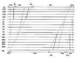
도 6은 도 5의 시차에 대한 도시 및 다양한 중간시점에서 상기 시차의 도면이다.
LC: 좌측 카메라 시점
RC: 우측 카메라 시점
Z1: 중간시점 1
Z2: 중간시점 2
Z3: 중간시점 3
Z4: 중간시점 4
Z5: 중간시점 5
PO1: O1의 물체 세그먼트의 투영
PO2: O2의 물체 세그먼트의 투영
PO3: O3의 물체 세그먼트의 투영
RV2: 물체 2의 우측 마스킹
RV3: 물체 3의 우측 마스킹
LV2: 물체 2의 좌측 마스킹
LV3: 물체 3의 좌측 마스킹
도 7은 도 5에 도시된 스테레오 간격-확장의 실행을 도시한 개략도이다.
LC: 좌측 카메라 시점
RC: 우측 카메라 시점
Z1: 중간시점 1
Z2: 중간시점 2
Z3: 중간시점 3
Z4: 중간시점 4
Z5: 중간시점 5
LE: 좌측 확장 시점
RE: 우측 확장 시점
PO1: O1의 물체 세그먼트의 투영
PO2: O2의 물체 세그먼트의 투영
PO3: O3의 물체 세그먼트의 투영
?: 내삽(interpolating) 할 새로운 좌측- 및 우측 마스킹
도 8은 포인터(pointer) pLC 및 pRC를 예로 도시한 도면이다.
LC: 좌측 카메라 시점
RC: 우측 카메라 시점
LE: 좌측 확장 시점
RE: 우측 확장 시점
PO1: O1의 물체 세그먼트의 투영
PO2: O2의 물체 세그먼트의 투영
PO3: O3의 물체 세그먼트의 투영
pLC(jl1): 측정된 카메라 시점 LC의 확장 시점 LE의 장소(jl1)에서 바라본 포인터
pRC(jl1): 측정된 카메라 시점 RC의 확장 시점 LE의 장소(jl1)에서 바라본 포인터
pLC(jl1*): 측정된 카메라 시점 LC의 확장 시점 LE의 장소(jl1*)에서 바라본 포인터
pRC(jl1*): 측정된 카메라 시점 RC의 확장 시점 LE의 장소(jl1*)에서 바라본 포인터
도 9는 LC의 스테레오 간격 외부에서 추가 중간시점의 발생을 도시한 개략도이다.
LC: 좌측 카메라 시점
RC: 우측 카메라 시점
Z1: 중간시점 1
Z2: 중간시점 2
Z3: 중간시점 3
Z4: 중간시점 4
Z5: 중간시점 5
LE: 좌측 확장 시점
RE: 우측 확장 시점
PO1: O1의 물체 세그먼트의 투영
PO2: O2의 물체 세그먼트의 투영
PO3: O3의 물체 세그먼트의 투영
?: 내삽(interpolating) 할 새로운 좌측- 및 우측 마스킹
LE1: 좌측 확장 시점 1
LE2: 좌측 확장 시점 2
LE3: 좌측 확장 시점 3
LE4: 좌측 확장 시점 4
LE5: 좌측 확장 시점 5
RE1: 우측 확장 시점 1
RE2: 우측 확장 시점 2
RE3: 우측 확장 시점 3
RE4: 우측 확장 시점 4
RE5: 우측 확장 시점 5
도 10은 좌측 마스킹의 가능성 및 좌측 마스킹의 처리를 도시한 개략도이다.
LC: 좌측 카메라 시점
RC: 우측 카메라 시점
LE: 좌측 확장 시점
RE: 우측 확장 시점
PO1: O1의 물체 세그먼트의 투영
PO2: O2의 물체 세그먼트의 투영
PO3: O3의 물체 세그먼트의 투영
?: 내삽(interpolating) 할 새로운 좌측- 및 우측 마스킹
도 11은 우측 마스킹의 가능성 및 우측 마스킹의 처리를 도시한 개략도이다.
LC: 좌측 카메라 시점
RC: 우측 카메라 시점
LE: 좌측 확장 시점
RE: 우측 확장 시점
PO1: O1의 물체 세그먼트의 투영
PO2: O2의 물체 세그먼트의 투영
PO3: O3의 물체 세그먼트의 투영
?: 내삽(interpolating) 할 새로운 좌측- 및 우측 마스킹
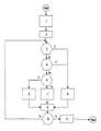
도 12는 전체 순수도이다.
1: LE_Where(어디로), pLC 및 pRC를 초기화함
2: jl1 := Anfang(시작)
3: Where(jl1) = -1?
Y: Yes(예)
N: No(아니오)
4: Where(jl1) - Where(jl1-1) = 0?
5: │Where(jl1) - Where(jl1-1)│ > 1?
6: 우측 마스킹 처리
7: 확장을 직접적으로 처리함
8: 좌측 마스킹 처리
9: jl1 = jl1 + 1
10: jl1 > Ende(끝)?
11: LE_Where(어디로)이 Where(어디로)으로 넘어감
도 13은 "우측 마스킹 처리"에 대한 순서도이다.
1: 좌측 가장자리에서 시차를 검출함
2: 우측 가장자리에서 시차를 검출함
3: 좌측 가장자리가 전방에?
Y: Yes
N: No
4: 좌측 가장자리에서 확장을 검출함
5: 우측으로 가서 우측 가장자리에서 확장을 검출함
6: 우측 가장자리에서 확장을 검출함
7: 좌측으로 가서 좌측 가장자리에서 확장을 검출함
8: 좌측 경계를 설정함
9: 우측 경계를 설정함
10: 좌측 LE_Where(어디로)로부터 -1을 갖는 jl1까지 채움
도 14는 "좌측 마스킹 처리"에 대한 순서도이다.
1: 좌측 경계가 정확하게 설정되었기 때문에, 확장이 상기 좌측 경계보다 처음으로 더 큰 우측 경계를 검색함
2: 우측 경계를 설정함
도 15는 분석된 장면의 복잡성 및 확장율에 따라 내삽될 화소의 퍼센티지에 대한 통계이다.
PE: %로 나타낸 확장율
%: HD-입체영상의 내삽될 화소의 퍼센티지
H: 복잡성이 높은 장면
L: 복잡성이 낮은 장면
사용된 축약어에 대한 설명
AE: 스테레오 카메라의 두 개 렌즈의 제공된 간격으로부터 발생 되는 상기 렌즈의 확장된 간격.
AA: 뷰어의 눈 간격.
AB: 디스플레이 장치로부터 뷰어의 좌측 및 우측 눈으로 투영되는 시점의 간격; "감지된 눈 간격"; 감지된 스테레오 간격.
SZ: 비주얼존의 폭; 비주얼존 폭.
KA: 스테레오 카메라의 렌즈 간격; 측정된 스테레오 간격 폭
N: 제공된 카메라 시점의 개수
M: 발생 된 확장 시점의 개수
DU: 최상의 깊이지각을 위해서 그 아래로 떨어져서는 안 되는, 디스플레이 장치상에 나타날 수 있는 시차의 하한.
DO: 최상의 깊이지각을 위해서 그 위로 초과해서는 안 되는, 디스플레이 장치상에 나타날 수 있는 시차의 상한.
F: 확장율.
PE: 제공된 입체영상의 최대 시차의 확장율.
LC: 제공된 가장 좌측의 카메라 시점.
PC: 제공된 가장 우측의 카메라 시점.
LE: LC의 좌측에 있는 가장 좌측의 확장 시점.
RE: RC의 우측에 있는 가장 우측의 확장 시점.
pLC: LC의 각각 사용될 측정된 화소 상에 있는 LE의 포인터의 필드.
pRC: RC의 각각 사용될 측정된 화소 상에 있는 LE의 포인터의 필드.
Where(어디로): 제공된 또는 계산된 시차의 필드; 시차 매트릭스의 i번째 행.
LE_Where(어디로): 계산되고 확장된 시차의 필드.
K: 제공된 입체영상의 행의 개수.
Dmax: 제공된 입체영상 내에서의 최대 시차.
ZW: 발생 된 중간시점의 개수.
DSTEP: 두 개의 중간시점 사이에 있는 스텝 폭의 크기.
NrP: 디스플레이할 시점의 개수.
jl1: i행 내에 있는 특정 화소 위치.
leftCapture: LC가 디스플레이되어야만 하는 바로 그 시점의 번호.
rightCapture: RC가 디스플레이되어야만 하는 바로 그 시점의 번호.
nrSegments: 화소 jl1의 시차가 주어진 경우에 시점 스텝당 화소의 개수.
leftBorder: 마스킹의 좌측 가장자리에서의 화소 위치.
rightBorder: 마스킹의 우측 가장자리에서의 화소 위치.
Anfang(시작): 한행의 처리할 처음 화소 위치.
Ende(끝): 한행의 처리할 마지막 화소 위치.
LE_Where_leftBorder: 시차가 최대 우측 스테레오 간격-확장(RE)까지 속행될 경우에 leftBorder에서의 시차.
LE_Where_rightBorder: 시차가 최대 우측 스테레오 간격-확장(RE)까지 속행될 경우에 rightBorder에서의 시차.1 is a schematic diagram showing the conversion of the stereo spacing of a stereo camera in the visual zone in the case of a multi-viewer display device as heretofore known.
LC: Left camera point
RC: right camera viewpoint
1: Viewer's eye space
2: Visual zone width at viewer position
3: Lens pitch of the stereo camera
4: Detected eye space
5: Display device
Figure 2 is a schematic diagram illustrating the conversion of the extended stereo spacing of a stereo camera by stereo spacing-expansion in the visual zone.
LC: Left camera position
RC: Right camera viewpoint
LE: left synthetic camera point
RE: Right synthesized camera point
1: Viewer's eye space
2: Visual zone width at viewer position
3: Lens pitch of the actual stereo camera
4: Detected eye space
5: Display device
3 is a schematic view showing a scene having three objects measured by a right lens of a stereo camera.
RR: right retina (retina)
O1:
O2:
O3:
PO1: Projection of object segment of O1
PO2: projection of object segment of O2
PO3: Projection of object segment of O3
Fig. 4 is a schematic view showing the same scene as in Fig. 3, measured by the left lens of the stereo camera. Fig.
LR: Left retina
O1:
O2:
O3:
PO1: Projection of object segment of O1
PO2: projection of object segment of O2
PO3: Projection of object segment of O3
Fig. 5 is a schematic diagram showing the disparity of the left image LC shown in Fig. 4 and the right image RC shown in Fig. 3;
LC: Left camera point
RC: right camera viewpoint
PO1: Projection of object segment of O1
PO2: projection of object segment of O2
PO3: Projection of object segment of O3
RV2: Right masking of
RV3: Right masking of
LV2: Left masking of
LV3: Left masking of
FIG. 6 is a view of the parallax of FIG. 5 and a diagram of the parallax at various intermediate times.
LC: Left camera point
RC: right camera viewpoint
Z1:
Z2:
Z3:
Z4: Midpoint 4
Z5:
PO1: Projection of object segment of O1
PO2: projection of object segment of O2
PO3: Projection of object segment of O3
RV2: Right masking of
RV3: Right masking of
LV2: Left masking of
LV3: Left masking of
FIG. 7 is a schematic diagram illustrating the execution of the stereo interval-spreading shown in FIG. 5;
LC: Left camera point
RC: right camera viewpoint
Z1:
Z2:
Z3:
Z4: Midpoint 4
Z5:
LE: Left expansion point
RE: Right expansion point
PO1: Projection of object segment of O1
PO2: projection of object segment of O2
PO3: Projection of object segment of O3
?: New left and right masking to interpolate
8 is a diagram showing pointers pLC and pRC as an example.
LC: Left camera point
RC: right camera viewpoint
LE: Left expansion point
RE: Right expansion point
PO1: Projection of object segment of O1
PO2: projection of object segment of O2
PO3: Projection of object segment of O3
pLC (jl1): Pointer viewed from the location jl1 of the extended time LE of the measured camera view LC
pRC (jl1): Pointer viewed from the location jl1 of the extended time LE of the measured camera view RC
pLC (jl1 *): Pointer viewed from the location (jl1* ) of the extended time LE of the measured camera point LC
pRC (jl1 *): Pointer viewed from the location (jl1 *) of the extended time LE of the measured camera view RC
Figure 9 is a schematic diagram showing the occurrence of an additional midpoint outside the stereo gap of the LC.
LC: Left camera point
RC: right camera viewpoint
Z1:
Z2:
Z3:
Z4: Midpoint 4
Z5:
LE: Left expansion point
RE: Right expansion point
PO1: Projection of object segment of O1
PO2: projection of object segment of O2
PO3: Projection of object segment of O3
?: New left and right masking to interpolate
LE1: Left
LE2: Left
LE3: Left
LE4: Left expansion point 4
LE5: Left
RE1:
RE2:
RE3:
RE4: right expansion point 4
RE5:
10 is a schematic diagram showing the possibility of left-side masking and the processing of left-side masking.
LC: Left camera point
RC: right camera viewpoint
LE: Left expansion point
RE: Right expansion point
PO1: Projection of object segment of O1
PO2: projection of object segment of O2
PO3: Projection of object segment of O3
?: New left and right masking to interpolate
11 is a schematic view showing the possibility of the right masking and the processing of the right masking.
LC: Left camera point
RC: right camera viewpoint
LE: Left expansion point
RE: Right expansion point
PO1: Projection of object segment of O1
PO2: projection of object segment of O2
PO3: Projection of object segment of O3
?: New left and right masking to interpolate
12 is a total pure water diagram.
1: LE_Where (where), pLC and pRC are initialized
2: jl1: = Anfang (start)
3: Where (jl1) = -1?
Y: Yes
N: No
4: Where (jl1) - Where (jl1-1) = 0?
5: │Where (jl1) - Where (jl1-1) │> 1?
6: Right masking process
7: Process extension directly
8: Left masking process
9: jl1 = jl1 + 1
10: jl1> Ende?
11: LE_Where (where to go)
13 is a flow chart for the "right masking process ".
1: Detects the parallax at the left edge
2: Detected parallax at the right edge
3: The left edge is on the front?
Y: Yes
N: No
4: Extension detected on the left edge
5: Go right and detect extension at the right edge
6: Extension detected on the right edge
7: go left and detect extension at the left edge
8: Set left boundary
9: Set right boundary
10: Fill from left LE_Where (where) to jl1 with -1
14 is a flow chart for "left masking process ".
1: Since the left boundary is set correctly, the extension searches for the first larger right boundary than the left boundary
2: Set right boundary
Figure 15 is a graph of the percentage of pixels to be interpolated according to the complexity and the rate of expansion of the scene analyzed.
PE: Expansion rate in%
%: Percentage of pixels to be interpolated in the HD-stereoscopic image
H: Highly complex scenes
L: Scenes with low complexity
A description of the abbreviation used
AE: Extended spacing of the lens resulting from the provided spacing of the two lenses of the stereo camera.
AA: The eye space of the viewer.
AB: the interval between the points of projection from the display device to the left and right eyes of the viewer; "Sensed eye space"; Detected Stereo Interval.
SZ: width of visual zone; Visual zone width.
KA: Lens gap of the stereo camera; Measured Stereo Spacing Width
N: Number of camera viewpoints provided
M: Number of expansion points generated
DU: The lower limit of the parallax that can appear on the display device, which should not fall below it for best depth perception.
DO: Upper limit of the parallax that can appear on the display device, not exceeding it for the best depth perception.
F: Expansion ratio.
PE: Maximum rate of parallax expansion of the provided stereoscopic image.
LC: Camera point of the leftmost provided.
PC: The rightmost camera point provided.
LE: The leftmost expansion point on the left side of the LC.
RE: The rightmost extension point to the right of the RC.
pLC: The field of the pointer of the LE on the measured pixel to be used in each of the LCs.
pRC: The field of the pointer of the LE on the measured pixel to be used for RC, respectively.
Where: a field of provided or calculated disparity; I-th row of the parallax matrix.
LE_Where (where): Field of calculated and extended time difference.
K: number of rows of the provided stereoscopic image.
Dmax: maximum parallax in the provided stereoscopic image.
ZW: Number of midpoints generated.
DSTEP: The size of the step width between the two midpoints.
NrP: Number of times to display.
jl1: a specific pixel position within the i-th row.
leftCapture: the number at which the LC should be displayed.
rightCapture: the number at which RC should be displayed.
nrSegments: Number of pixels per viewpoint step, given the parallax of pixel jl1.
leftBorder: The pixel position at the left edge of the masking.
rightBorder: The pixel position at the right edge of the masking.
Anfang: The first pixel position to process a single line.
Ende: The position of the last pixel to process a line.
LE_Where_leftBorder: Parallax in leftBorder when the parallax is continued up to the right-most stereo interval-extension (RE).
LE_Where_rightBorder: Parallax at rightBorder when the parallax is continued up to the right-most stereo interval-extension (RE).
이하, 본 발명에 따른 처리 단계들에 대해 자세히 설명한다.Hereinafter, the processing steps according to the present invention will be described in detail.
이하의 설명은 편의상 아래 가정들을 기초로 하지만, 이에 한정되는 것도 아니다.The following description is based on, but not limited to, the following assumptions for convenience.
1. 카메라 시점의 갯수(N)는 2이다. 갯수가 더 크면, 제공된 카메라 시점들 중의 특정 카메라 시점이 중간시점으로 사용된다.1. The number of camera viewpoints (N) is 2. If the number is greater, a particular camera view of the provided camera viewpoints is used as the midpoint.
2. 입체영상을 정상적인 입체 형태로 공급하여, 모든 계산을 한줄씩 할 수 있다. 한편, 에피폴라(epipolar) 선을 따라 교정을 할 수도 있다.2. Stereoscopic images can be supplied in a normal stereoscopic shape, and all calculations can be done in one line. On the other hand, calibration can be done along the epipolar line.
3. 입체영상 외에 시차지도(disparity map)이 사용된다. 시차지도는 입체영상과 같이 제공되거나 미리 제공된다. 상기 시차지도에서 Where은 i번째 행에 있다.3. In addition to stereoscopic images, a disparity map is used. The time difference map is provided or provided in advance as a stereoscopic image. Where in the time difference map is located in the i-th row.
4. 이하 언급되는 모든 비주얼존(visual zones)은 항상 평행하다고 본다.4. All visual zones mentioned below are considered to be parallel at all times.
전술한 바와 같이, 본 발명의 방법의 목적은, 멀티뷰어 디스플레이 장치의 광학 수단에 의해 규정된 비주얼존에서 심도를 개선하기 위해 카메라 시점이 N≥2인 입체영상을 기초로 스테레오 카메라에 사용되는 스테레오 간격(KA)의 확장을 하는데 있다. 모든 무안경 멀티뷰어 디스플레이 장치의 광학 수단은, 각각의 비주얼존에서 비주얼존 좌측 가장자리에 제공된 좌측 카메라 시점과 우측 가장자리에 제공된 우측 카메라 시점을 지각한다. 이런 지각은 디스플레이 장치 앞에 있는 모든 장소에서 적용된다. 비주얼존의 폭(SZ)이 뷰어의 눈 간격(AA)보다 크면, 뷰어는 이 비주얼존에서 자유롭게 움직일 수 있어, 비주얼존 폭(SZ)을 최대로 하는 게 바람직하다.As described above, the object of the method of the present invention is to improve the depth in the visual zone defined by the optical means of the multi-viewer display device, in order to improve the depth in the stereoscopic image, To expand the interval KA. The optical means of all the eyeglass multi-view display devices perceives the left camera view provided at the left side of the visual zone in the respective visual zones and the right camera view provided at the right edge. This perception is applied at all places in front of the display device. If the width SZ of the visual zone is larger than the viewer's eye interval AA, the viewer is free to move in this visual zone, and it is desirable to maximize the visual zone width SZ.
뷰어의 눈 간격(AA)에 따라서 항상 두 개의 상이한 중간시점이 좌측 및 우측 눈에 각각 투영된다(도 1 참조). 이때 뷰어가 감지하는 깊이지각은 투영된 두 시점의 간격에 의존한다(도 1의 요소 4). 투영된 두 시점의 간격이 넓을수록 깊이지각이 갱해지며, 이 간격이 좁을수록 깊이지각은 약해진다. 극단의 경우에, 시점 간격이 0이면, 뷰어는 하나의 2D-영상만 보게 된다. 시점 간격이 최대이면, 다시 말해 좌측 눈이 좌측 카메라 시점을 보고 우측 눈이 우측 카메라 시점을 보게 되면, 예컨대 3D-안경 기반 디스플레이와 마찬가지로 깊이지각도 최대가 된다.Two different intermediate viewpoints are always projected to the left and right eyes, respectively, according to the viewer's eye clearance AA (see FIG. 1). At this time, the depth perception that the viewer perceives depends on the spacing of the projected two views (element 4 in FIG. 1). The wider the gap between the two projected points, the deeper the perception becomes, and the narrower the interval, the weaker the depth perception. In extreme cases, if the view interval is zero, the viewer sees only one 2D-image. If the viewpoint interval is the maximum, that is, if the left eye sees the left camera view and the right eye sees the right camera view, the depth perception is also maximized, as for example a 3D-glasses based display.
다시 말해 본 발명의 목적은 비주얼존의 폭(SZ)과 눈의 간격(AA)이 주어진 경우 두 개의 투영된 시점 간격을 가급적 넓게하는데 있다.In other words, the object of the present invention is to broaden the two projected time intervals as much as possible when the width (SZ) of the visual zone and the eye interval (AA) are given.
이 목적은 스테레오 카메라의 주시 방향으로 볼 때 좌우측 비주얼존의 좌우측 가장자리에 제공된 카메라 시점(LC,RC)에 의해 투영되는 가상의 확장 시점(LE,RE)을 설정해 달성된다(도 2 참조). 도 2에 따르면, 확장 시점(LE,RE)은 좌우측 카메라 시점(LC,RC)의 스테레오 간격(3)의 연장선에 있다. 비주얼존 내부의 임의의 한점에서 좌우측 눈에 각각 투영되는 두 시점의 간격인 감지된 눈간격을 AB라 하면, 아래와 같다:This object is achieved by setting virtual extension points LE and RE projected by the camera view points LC and RC provided on the left and right edges of the left and right visual zones when viewed in the viewing direction of the stereo camera (see FIG. 2). 2, the expansion timings LE and RE are on the extension of the
AB = AA * KA / SZ(1)AB = AA * KA / SZ (1)
KA=65mm, SZ=300mm, AA=63mm인 경우, 감지된 눈 간격(AB)은 13.7mm이다.When KA = 65 mm, SZ = 300 mm, and AA = 63 mm, the detected eye clearance AB is 13.7 mm.
그러나, 스테레오 간격이 후술하는 것처럼 예컨대 PE=200%로 확장되면, 좌측 확장 시점(LE)은 스테레오 간격(3) 상에서 100% 확장되어, 65mm 더 좌측으로 확장되며, 우측 확장 시점(RE)도 스테레오 간격(3) 상에서 100% 확장되어, 65mm 더 우측으로 확장된다. 이 경우 아래와 같다:However, if the stereo interval is expanded to, for example, PE = 200% as described below, the left extension point LE is extended 100% on
AB = 63 * (3 * 65) / 300 = 40.9 mm(2)AB = 63 * (3 * 65) / 300 = 40.9 mm (2)
상기 예에서 감지된 깊이지각은 65 mm의 실제 깊이지각과 거의 동일하다.The depth perception detected in the above example is approximately equal to the actual depth perception of 65 mm.
측정된 스테레오 간격(KA)이 확장되는 확장율을 F라 하면, (1)은 아래와 같이 일반화될 수 있다:If the expansion rate at which the measured stereo interval (KA) expands is F, then (1) can be generalized as:
AB = F* AA * KA / SZ.(3)AB = F * AA * KA / SZ. (3)
눈간격(AA)과 비주얼존 폭(SZ)이 주어지고 스테레오 간격 폭(KA)이 측정된 경우, 확장율(F)을 감지된 스테레오 간격 폭(AB)으로 결정하면 아래와 같다:Given the eye spacing AA and the visual zone width SZ and the stereo spacing width KA measured, the expansion ratio F is determined as the sensed stereo spacing width AB:
F = AB * SZ / (KA * AA). (4)F = AB * SZ / (KA * AA). (4)
실제와 같은 깊이지각을 발생시키고 싶다면, 즉 AB = AA를 원할 경우 아래와 같다:If you want to create a real depth perception, ie you want AB = AA:
F = SZ / KA(5)F = SZ / KA (5)
카메라 렌즈의 간격(KA)에는 아무런 영향도 미치지 않는다. 상기 카메라 렌즈의 간격은 약 65mm일 가능성이 크다. 따라서, 실제로는 아래와 같은 확장율(F)에서 출발한다:The distance KA of the camera lens is not affected. The distance between the camera lenses is likely to be about 65 mm. Therefore, it actually starts at the following expansion rate (F):
F = 0.0154 * SZ(6)F = 0.0154 * SZ (6)
비주얼존 폭 SZ=600mm이면, 확장율 F = 9.2이다.If the visual zone width SZ = 600 mm, the expansion rate F = 9.2.
F = 1 + PE /100 (7)F = 1 + PE / 100 (7)
일 경우, 약 400%의 확장(PE)이 일어나, 좌우측으로 각각 260mm의 확장이 일어난다., There is about 400% expansion (PE), resulting in a 260 mm expansion to the left and right, respectively.
제1 실시예에서는, 제공된 시차지도를 기초로 스테레오 간격 확장이 어떻게 이루어지는지를 설명한다. 이와 관련해 도 3~4에는 세 개의 물체(O1,O2,O3)를 갖는 하나의 장면을 예로 든다. 각 도면의 하부 영역에는 뷰어의 우측 눈의 망막(도 3)과 좌측 눈의 망막(도 4)에 대한 투영이나 카메라 렌즈 내부에 대한 개별적인 투영이 도시되어 있다. 이 경우에는 하나의 우측 눈(도 3)과 하나의 좌측 눈(도 4)의 개별 행(i)이 도시되어 있다. 상부 영역에는 디지털 사진에 저장된 바와 같이, 그리고 본 출원서에 기재된 방법에 의한 확장 및 미러링(mirroring) 후의 투영이 각각 도시되어 있다.In the first embodiment, how stereo interval expansion is performed based on the provided time difference map will be described. In this connection, FIGS. 3-4 illustrate one scene having three objects (O1, O2, O3). In the lower region of each of the figures, projections to the retina (FIG. 3) of the right eye of the viewer and the retina of the left eye (FIG. 4) or individual projections to the inside of the camera lens are shown. In this case, a separate row (i) of one right eye (FIG. 3) and one left eye (FIG. 4) is shown. The upper region is shown as projected in digital photographs, and after expansion and mirroring by the method described in the present application.
도 5에는 해당 연결선들과 관련된 시차관계가 도시되어 있다. 도 5는 물체(O2,O3)의 우측 마스킹 영역(RV2,RV3)도 보여준다.FIG. 5 shows the parallax relationship associated with the connection lines. Fig. 5 also shows the right masking areas RV2 and RV3 of the objects O2 and O3.
시점들 사이에서 LC에서 RC까지 가상의 카메라가 움직일 때, 같은 구간에서는 해당 화소에 대해 등거리로 시차들이 분할되도록 된다(도 6 참조). RC에서 LC로 움직일 때도 마찬가지다.When the virtual camera moves from LC to RC between the viewpoints, the parallaxes are equidistantly divided over the same pixel in the same interval (see FIG. 6). The same is true when moving from RC to LC.
Where(어디로) 필드에는, 시차지도의 규정에 따라 좌측 카메라 시점(LC)의 각각의 화소(Jl1)이 우측 카메라 시점(RC)에서이 어느 화소(jl1)에 대응하는지 표시된다.In the Where field, which pixel Jl1 in the left camera view LC corresponds to which pixel jl1 in the right camera view RC according to the definition of the time difference map.
이때 스테레오 간격 확장을 실행코자 하면, 도 5에 도시된 대응 선들이 LC와 RC를 지나 확장하는 것을 상상할 수 있다. 이는 LC와 RC를 넘어 스테레오 간격(KA)의 선형 확장에 해당한다(도 7 참조). 이 방식은 LC와 RC 사이의 중간시점들이 LC와 RC 사이에서의 선형 카메라 이동과 동기적으로 생기기 때문에 바람직하다. 이런 카메라 이동은 어느 정도까지는 LC와 RC를 넘어 계속된다.At this time, if it is desired to perform the stereo interval expansion, it is conceivable that the corresponding lines shown in Fig. 5 extend beyond LC and RC. This corresponds to a linear extension of the stereo spacing (K A) beyond LC and RC (see FIG. 7). This approach is desirable because the midpoints between LC and RC occur synchronously with linear camera movement between LC and RC. This camera movement goes beyond LC and RC to some extent.
그러나, 이 경우 해결해야만 할 아래와 같은 문제점들이 생긴다:However, this leads to the following problems that must be solved:
1. 비주얼존에서의 LC와 RC에 대한 새로운 시점 위치의 계산,1. Calculation of new viewpoint positions for LC and RC in the visual zone,
2. LE와 RE의 화소의 계산,2. Computation of LE and RE pixels,
3. 확장시 충돌이 있을 경우 어떤 시차를 계속해야할지 결정,3. If there is a conflict during expansion, determine which time difference to continue,
4. 스테레오 간격의 확장을 통해 보일 수 있는 영상 구역을 내삽하는 방법.4. A method of interpolating image regions that can be viewed through the expansion of the stereo spacing.
1. 비주얼존에서의1. In the Visual ZoneLC와With LCRC에 대한 새로운New for RC시점 위치의 계산Calculation of the viewpoint position
NrP 시점을 디스플레이할 경우, 종래의 디스플레이 장치처럼 LC는 시점 0에 사용되고, RC는 시점 NrP-1에 사용된다.When displaying the NrP time point, the LC is used at the
이것은 스테레오 간격 확장에서는 일어나지 않고 아래와 같이 일반화된다:This does not occur in stereo spacing expansion and is generalized as follows:
leftCapture가 LC에 디스플레이할 시점의 번호라면, 아래와 같다:If leftCapture is the number that you want to display on the LC:
leftCapture := (NrP - 1) * (1 - 1 / F)/2(8)leftCapture: = (NrP - 1) * (1 - 1 / F) / 2 (8)
rightCapture := leftCapture + (NrP - 1) / F(9)rightCapture: = leftCapture + (NrP - 1) / F (9)
확장율 PE=0%이면, F=1이고 leftCapture=0이며, rightCapture=NrP-1이다. 이때문에 이런 방식은 종래의 방식과 같이 사용할 수 있다.If the expansion rate PE = 0%, then F = 1, leftCapture = 0, and rightCapture = NrP-1. Therefore, this method can be used like the conventional method.
한편, 예컨대 PE=200%이면, 스테레오 간격은 좌우측으로 각각 100% 확장되고, LC와 RC는 각각 1/3만큼 안쪽으로 이동할 것이다. 이 경우, 식 (8)과 (9)는 leftCapture = 1/3*(NrP - 1), rightCapture = 2/3*(NrP - 1)로 되며, 이는 기대한대로이다. .On the other hand, if, for example, PE = 200%, the stereo spacing will extend 100% to the left and right respectively, and LC and RC will move inward by 1/3 respectively. In this case, equations (8) and (9) are leftCapture = 1/3 * (NrP - 1) and rightCapture = 2/3 * (NrP - 1). .
2.2.LE와With LERERE의 화소의 계산Of pixels
위치 jl1에 좌측 시점이 디스플레이되었다면, 화소 LC(jl1)에 액세스할 것이다. 대응 화소가 우측 시점으로부터 디스플레이된다면, 화소 RC(Where(jl1))에 액세스할 것이다.If the left viewpoint is displayed at the position jll, it will access the pixel LC (jl1). If the corresponding pixel is displayed from the right viewpoint, it will access the pixel RC (Where (jl1)).
이는 LE(jl1)와 RE(Where(jl1))가 규정되지 않았기 때문에 스테레오 간격 확장에서는 불가능하다. 이때문에, 좌측 시점이 디스플레이될 때는, LE로부터 액세스되는 LC에 의해 화소의 위치가 저장되는 필드 pLC가 도입된다. 마찬가지로, 우측 시점이 디스플레이될 때는, 시차의 함수로 LE로부터 액세스 되는 RC에 의해 화소의 위치가 저장되는 필드 pRC가 도입된다.This is not possible with stereo spacing extension because LE (jl1) and RE (Where (jl1)) are not specified. Therefore, when the left view is displayed, the field pLC in which the position of the pixel is stored by the LC accessed from the LE is introduced. Likewise, when the right view is displayed, a field pRC is introduced in which the position of the pixel is stored by RC accessed from the LE as a function of the parallax.
이 방법은 아래와 같이 시작된다:This method starts as follows:
pLC(jl1) := jl1 (10)pLC (jl1): = jl1 (10)
pRC(jl1) := Where(jl1)pRC (jl1): = Where (jl1)
도 8에서 보듯이, jl1에서 LE나 RE로부터의 화소가 필요하면,As shown in Fig. 8, if a pixel from LE or RE is required in jl1,
LE(jl1) := LC(pLC(jl1)) (11)LE (jl1): = LC (pLC (jl1)) (11)
RE(Where(jl1)):= RC(pRC(jl1))(12)RE (Where (jl1)) = RC (pRC (jl1)) (12)
따라서, 이상 설명한 방법은 확장율 PE = 0%일 경우 종래의 방법과 양립할 수 있다.Therefore, the above-described method can be compatible with the conventional method when the expansion ratio PE = 0%.
3. 확장시 충돌이 있을 경우 어떤 시차를 계속해야할지 결정3. If there is a conflict during expansion, determine which time difference to continue
좌우측 마스킹의 경우, 확장된 시차가 연장구역의 에지에서 교차하면서 마스킹 영역들의 에지에서 충돌이 발생할 수 있다. 그 일례가 좌측 마스킹에 대해서는 도 10에, 우측 마스킹에 대해서는 도 11에 도시되어 있다. 결국에는 "전방에 어떤 물체가 있는가"라는 질문에 대한 답변이 이루어져야만 한다. 이 물체의 시차가 계속되는 반면, 다른 물체의 시차는 새로운 마스킹이나 기존의 마스킹의 확장을 일으킨다.In the case of left and right masking, collision may occur at the edges of the masking areas while the extended parallax intersects at the edge of the extension area. An example thereof is shown in Fig. 10 for the left masking and Fig. 11 for the right masking. In the end, the answer to the question "what object is ahead" must be answered. While the parallax of this object continues, parallax of other objects causes new masking or extension of existing masking.
이에 대한 답변은 '정상적인 입체 형상의 경우, 시차는 스테레오 카메라에서 물체까지의 거리에 반비례한다'이다. 시차가 더 큰 물체가 다른 물체의 전방에 있는데, 이는 시차가 더 큰 물체가 스테레오 카메라에 더 가까이 있으면서 다른 물체를 가리기 때문이다.The answer is that in the case of a normal three-dimensional shape, the parallax is inversely proportional to the distance from the stereo camera to the object. The object with the larger parallax is in front of the other object because the object with larger parallax is closer to the stereo camera and covers the other object.
구체적으로, 충돌시 에지의 시차를 검사하면, 시차가 더 큰 화소들은 추적되지만, 다른 화소들은 가려진다(도 10 및 도 11 참조).Specifically, by examining the parallax of the edge at the time of the collision, pixels with larger parallax are tracked, while other pixels are obscured (see FIGS. 10 and 11).
4. 스테레오 간격의 확장을 통해 볼 수 있는 영상구역을 내삽하는 방법4. How to interpolate image regions that can be viewed through the expansion of stereo spacing
스테레오 간격을 좌우측으로 확장하면 영상정보가 존재하지 않는 구역 내부의 영역들을 볼 수 있는데, 이는 이 영역들이 지금까지는 가려져있었기 때문이다. 예컨대 도 4의 물체 O3와 같이 더 뒤에서 전방 물체를 볼 수 있다. 도 7에는 이런 영역이 ?로 표시되어 있다.Expanding the stereo gap to the left and right allows you to see areas within the area where no image information is present, as these areas have been hidden so far. For example, as in the object O3 in Fig. 4, a forward object can be seen from behind. This area is marked with? In Fig.
본 발명에서는 최종적으로 보이는 화소가 반복될 수 있어야 한다.In the present invention, the finally visible pixel must be repeatable.
좌측 마스킹의 경우, 인접하는 좌측 마스킹의 최좌측 화소가 반복된다. 우측 마스킹의 경우, 인접하는 우측 마스킹의 최우측 화소가 반복된다. 이웃하는 화소들에 대한 일반적인 평활화는 이루어지지 않는데, 이는 이런 평활화가 물체 에지를 희미하게 할 수 있고, 이 경우 3D 효과가 저하되기 때문이다.In the case of the left masking, the leftmost pixel of the adjacent left masking is repeated. In the case of right masking, the rightmost pixel of the adjacent right masking is repeated. The normal smoothing for neighboring pixels is not done because this smoothing may cause the object edges to blur and in this case the 3D effect is degraded.
이 경우 관련 부정확도는 예상만큼 크지 않은데, 이는 실제 디스플레이될 화소들만 내삽해야 하기 때문이다. HD-해상도를 갖는 입체영상에서 실시된 조사에 의하면, 복잡한 장면에서는 물론 백분율로 표시된 스테레오 간격 확장(PE)이 500%인 경우에도 내삽된 화소의 백분율은 4% 미만임을 보여준다. 단순한 장면에서는 내삽된 화소의 백분율이 2% 미만이다. 한편, 감지된 깊이지각은 디스플레이된 입체영상에 비해 크게 개선된다.In this case, the associated inaccuracy is not as large as expected, since only the pixels to be displayed are interpolated. Surveys of stereoscopic images with HD-resolution show that the percentage of interpolated pixels is less than 4% even at a complex scene, as well as at a 500% stereo spacing extension (PE), expressed as a percentage. In a simple scene, the percentage of interpolated pixels is less than 2%. On the other hand, the sensed depth perception is greatly improved compared to the displayed stereoscopic image.
도 15에는 0%부터 500%까지 백분율로 나타낸 스테레오 간격 확장에 대해 복잡도가 높은 장면(H)과 복잡도가 낮은 장면(H)에서 영상의 전체 화소의 내삽될 화소의 개수가 %로 도시되어 있다.In FIG. 15, the number of pixels to be interpolated in all the pixels of the image in the high-complexity scene H and the high-complexity scene H is shown in% for the stereo interval expansion expressed as a percentage from 0% to 500%.
따라서, 문제의 해결책이 발견되었다.Thus, a solution to the problem has been found.
도 12는 본 발명에 따른 방법의 순서도이다.Figure 12 is a flow chart of the method according to the invention.
우선 필드 LE_Where이 -2로 설정되고, pLC와 pRC는 전술한대로 설정된다.The priority field LE_Where is set to -2, and pLC and pRC are set as described above.
다음, 한 라인의 모든 화소에 적용되는 루우핑 변수(jl1)가 시작값으로 설정된다.Next, the looping
"Where(jl1)=-1 ?"라는 질문으로 jl1에 우측 마스킹이 있는지 검사한다. "Yes"이면 "우측 마스킹 처리"가 진행되고, "No"이면 "Where(jl1) - Where(jl1-1) = 0 ?"라는 질문으로 확장부에 새로운 우측 마스킹이 나타나는지 검사한다. "Yes"이면 "우측 마스킹 처리"가 진해되고, "No"이면 아래 유효여부를 검사한다:The question "Where (jl1) = - 1?" Checks jl1 for right masking. If "Yes", the right masking process is performed. If "No", a question of "Where (jl1) - Where (jl1-1) = 0?" Is checked to see if a new right masking appears in the extension. If "Yes", the "right masking processing" is advanced, and if "No", the following validity is checked:
│Where(jl1) - Where(jl1-1)│ > 1(15)Where (jl1) - Where (jl1-1)> 1 (15)
위의 식을 만족하면 "좌측 마스킹 처리"가 진행되고, 아니면 "확장 직접 계산"이 진행된다. 다음, 모든 경우 "jl1=jl1+1"의 증분이 이루어지고, "jl1>끝"의 여부가 체크된다. 이제 좌우측 마스킹이 확인되고, "우측 마스킹 처리"와 "좌측 마스킹 처리"를 부분적으로 정확하게 유지보완하는 단계들이 실행될 수 있다.If the above expression is satisfied, the "left masking process" proceeds, or "extended direct calculation" proceeds. Next, in all cases, the increment of "jl1 = jl1 + 1" is made, and whether or not "jl1> end" is checked. Now left and right masking is confirmed, and steps of partially maintaining and correcting the "right masking process" and the "left masking process"
그 경우에 해당한다면, LE_Where은 Where으로 넘어가게 된다. 그 다음에 영상합성의 선택된 방법이 새롭게 설정된 시차에 근거하여, 하지만 새로운 포인터 pLC 및 pRC를 사용해서 실시될 수 있다.If so, then LE_Where goes to Where. The selected method of image synthesis is then based on the newly set time difference, but can be performed using the new pointers pLC and pRC.
이하 "우측 마스킹 처리" 단계를 자세히 설명한다. 이 단계가 도 13의 순서도로 도시되어 있다. "Where(jl1)=-1"이나 "Where(jl1)-Where(jl1-1)=0"이 확인되면, 영역의 좌측 에지에서의 시차가 결정된다. "Where(jl1)=-1"인 경우, 좌측 에지는 "Where(leftBorder)>0"인 화소 인덱스 leftBorder이거나, Where(jl1) 및 Where(jl1-1)이 우측 카메라 시점(RC)에서 동일 화소 상에 나타날 때의 "leftBorder=jl1-1"이다.The "right masking processing" step will be described in detail below. This step is shown in the flowchart of Fig. When "Where (jl1) = -1" or "Where (jl1) -Where (jl1-1) = 0" is confirmed, the parallax at the left edge of the area is determined. The left edge is the pixel index leftBorder of "Where (leftBorder)> 0", or Where (jl1) and Where (jl1-1) are the pixel indexes at the right camera view (RC) Quot; leftBorder = jl1-1 "
"rightBorder=jl1"이거나 처음에 "Where(rightBorder)>0"일 때는 우측 에지에 동일한 내용이 적용된다.When "rightBorder = jl1" or "Where (rightBorder)> 0" for the first time, the same applies to the right edge.
다음, 좌측 에지(leftBorder)의 시차가 우측 에지(rightBorder)의 시차보다 큰지를 검사한다. 아래와 같이 크다면, 물체는 전방 좌측 에지에 있게 된다.Next, it is checked whether the parallax of the left edge (leftBorder) is larger than the parallax of the right edge (rightBorder). If it is large as shown below, the object will be at the front left edge.
시차(leftBorder) > 시차(rightBorder)(16)LeftBorder>
이를 위해 먼저 leftBorder에서의 시차가 최대 우측 스테레오 간격 확장(RE)까지 진행된다. 값 LE_Where_leftBorder가 나타난다. 마찬가지로 LE_Where_rightBorder가 결정된다. 이때 rightBorder는 "LE_Where_leftBorder≤LE_Where_rightBorde"r가 유효할 때까지 증분된다. 이 장소에서 우측 마스킹의 확장도 종료된다.To do this, the parallax in the leftBorder first goes to the maximum right stereo gap extension (RE). The value LE_Where_leftBorder appears. Likewise, LE_Where_rightBorder is determined. RightBorder is incremented until "LE_Where_leftBorder ≤LE_Where_rightBorde" r is in effect. The extension of the right masking is also terminated at this location.
한편, 식 (16)이 만족되지 않으면, 물체는 전방 우측 에지에 있게 된다. 이 경우, 전술된 바와 같이 우선 rightBorder에서의 시차가 최대 우측 스테레오 간격 확장(RE)까지 진행된다. 이 경우에도 LE_Where_rightBorder가 나타난다.On the other hand, if equation (16) is not satisfied, the object is at the front right edge. In this case, as described above, first, the parallax in rightBorder is advanced to the maximum right stereo interval extension RE. In this case, LE_Where_rightBorder appears.
이때 LE_Where_leftBorder가 새로 결정된다. 이를 위해, leftBorder는 마찬가지로 아래 값을 이룰 때까지 증분된다:LE_Where_leftBorder is newly determined. To do this, leftBorder is similarly incremented until it reaches the following value:
LE_Where_leftBorder ≤ LE_Where_rightBorder(17)LE_Where_leftBorder? LE_Where_rightBorder (17)
이 장소에서도 마찬가지로 우측 마스킹의 확장이 종료된다.Likewise, extension of right masking is terminated at this place.
leftBorder 및 rightBorder가 결정된 후, LE 좌측으로 leftBorder 및 rightBorder의 속행이 결정된다. 이를 위해, 먼저 아래가 계산된다:After leftBorder and rightBorder are determined, the continuation of leftBorder and rightBorder to LE left is determined. To do this, the following is first calculated:
LeftStep := (Where(leftBorder) - leftBorder)/NrSegments(18)LeftStep: = (Where (leftBorder) - leftBorder) / NrSegments (18)
다음, 아래가 계산된다:Then, the following is calculated:
LeftExtension = leftBorder - leftCapture * leftStep(19)LeftExtension = leftBorder - leftCapture * leftStep (19)
이때,At this time,
pLC(leftExtension) = leftBorder,pLC (leftExtension) = leftBorder,
pRC(leftExtension) = Where(leftBorder)pRC (leftExtension) = Where (leftBorder)
LE_Where(leftExtension) =LE_Where (leftExtension) =
Where(leftBorder) + (NrP - rightCapture -1)/leftStep(20)Where (leftBorder) + (NrP - rightCapture - 1) / leftStep (20)
이 설정될 수 있다.Can be set.
마찬가지로, rightBorder로부터 rightStep, rightExtension 그리고 pLC(rightExtension), pRC(rightExtension) 및 LE_Where(rightExtension)이 나타난다. 이런 단계들은 당업자들에게는 익숙하다.Similarly, rightStep, rightExtension, and pLC (rightExtension), pRC (rightExtension), and LE_Where (rightExtension) appear from rightBorder. These steps are familiar to those skilled in the art.
마지막으로, LE_Where에서 우측 마스킹을 일정하게 마킹(marking)하기 위하여, LE_Where은 leftExtension부터 rightExtension까지 -1로 설정된다. 이때 LE_Where에서 -1의 값은 기존 우측 마스킹의 화소를 표시하고, -2의 값은 내삽되어야할 새로 공개된 화소를 표시한다. 도 11은 다양한 시나리오 및 전술한 조치 방식에 상응하는 상기 시나리오의 처리를 보여주고 있다.Finally, LE_Where is set to -1 from leftExtension to rightExtension in order to constantly mark the right masking in LE_Where. In this case, a value of -1 in LE_Where indicates pixels of the existing right masking, and a value of -2 indicates a newly opened pixel to be interpolated. Fig. 11 shows the processing of the above scenario corresponding to various scenarios and the above-mentioned measures.
새 우측 마스킹에도 전술한 것과 다른 방식을 요구하지는 않는다.New right masking does not require a different approach than that described above.
"좌측 마스킹 처리"의 경우에는 아래와 같이 조치가 필요하다:In the case of "left masking", the following action is required:
이 경우, 식 (15)가 적용된다. 다양한 상황과 이에 대한 처리방식에 대해서는 도 10의 실시예를 참조할 수 있다.In this case, equation (15) is applied. For the various situations and the processing method therefor, the embodiment of FIG. 10 can be referred to.
이 경우 좌측 경계(leftBorder)가 자동으로 정확하게 설정되었다. 따라서, 우측경계(rightBorder)만 우측으로 아래와 같이 증분한다:In this case, the left border (leftBorder) was automatically set correctly. Therefore, only the right border (rightBorder) is incremented to the right as shown below:
LeftExtension ≤ rightExtension(21)LeftExtension < = rightExtension (21)
leftExtension과 rightExtension은 전술한 바와 같고, 시작값 leftBorder:=jl1-1과 rightBorder:=jl1이 계산된다. 이제 pLC(rightExtension), pRC(rightExtension) 및 LE_Where(rightExtension)은 아래와 같이 계산된다:The leftExtension and rightExtension are as described above, and the starting values leftBorder: = jl1-1 and rightBorder: = jl1 are calculated. Now the pLC (rightExtension), pRC (rightExtension) and LE_Where (rightExtension) are calculated as follows:
pLC(rightExtension) = rightBorder,pLC (rightExtension) = rightBorder,
pRC(rightExtension) = Where(rightBorder)pRC (rightExtension) = Where (rightBorder)
LE_Where(rightExtension) =LE_Where (rightExtension) =
Where(rightBorder) + (NrP - rightCapture -1)/leftStep(22).Where (rightBorder) + (NrP - rightCapture - 1) / leftStep (22).
관련 순서도는 도 14와 같다.The related flowchart is shown in Fig.
따라서, 스테레오 간격-확장시의 모든 충돌이 광학적으로 정확하게 처리된다.Thus, all the collisions at the stereo gap-extension are optically processed correctly.
마스킹이 없으면, jl1과 jl1 - 1 사이의 시차는 바뀌지 않는다. 즉, 아래와 같다:Without masking, the parallax between jl1 and jl1 - 1 does not change. That is:
│Where(jl1) - Where(jl1-1)│ = 1(23)Where (jl1) - Where (jl1-1) = 1 (23)
이 경우에 jl1Extension은 (19)에 의해 아래와 같고,In this case, jl1Extension is given by (19) below,
jl1Extension = jl1 - leftCapture * jl1Step(24)jl1Extension = jl1 - leftCapture * jl1Step (24)
pLC(jl1Extension), pRC(jl1Extension), LE_Where(jl1Extension)은 아래와 같으며:pLC (jl1Extension), pRC (jl1Extension), LE_Where (jl1Extension) are as follows:
pLC(jl1Extension) = jl1,pLC (jl1Extension) = jl1,
pRC(jl1Extension) = Where(jl1)pRC (jl1Extension) = Where (jl1)
LE_Where(jl1Extension) =LE_Where (jl1Extension) =
Where(jl1) + (NrP - rightCapture -1)/leftStep(25),Where (jl1) + (NrP - rightCapture - 1) / leftStep (25)
이 경우, 아래와 같다:In this case:
jl1Step = (Where(jl1) - jl1) / NrSegments(26)jl1Step = (Where (jl1) - jl1) / NrSegments (26)
LE_Where이 Where로 옮겨진 후, 스테레오 간격 확장을 위한 시차지도를 만들어 LE와 RE 사이의 모든 NrP 시점을 합성하는데 사용한다(도 9 참조).After LE_Where is moved to Where, it is used to create a time difference map for stereo spacing expansion to synthesize all NrP points between LE and RE (see FIG. 9).
제2 실시예에서는 뷰어의 원격조작으로 확장율(F)을 양방향으로 조절하여, 깊이지각을 각 개인에 맞추도록 한다.In the second embodiment, the expansion rate F is adjusted in both directions by the remote operation of the viewer so that the depth perception is adjusted to each individual.
제3 실시예에서는 확장율(F)이 아래와 같이 자동으로 계산된다:In the third embodiment, the expansion rate F is automatically calculated as follows:
과거의 연구로, 무안경 디스플레이에 나타난 영상들의 최대 시차(D)가 소정의 한계를 넘어서는 안됨이 밝혀졌데, 이는 한계를 넘어 나타난 시점들을 사람의 뇌가 더 이상 하나의 입체영상으로 조합할 수 없기 때문이다.Previous studies have shown that the maximum parallax (D) of images displayed on a non-eyeglass display should not exceed a predetermined limit, since it is not possible to combine the points of view beyond the limit into a single stereoscopic image Because.
이런 최대 시차(D)는 예컨대 디스플레이의 해상도나 광학소자의 광학 특성들과 같은 다양한 변수에 의존한다. 이때문에 디스플레이를 설계할 때는 최대시차(D)를 규정해야 한다. 깊이지각을 항상 최대로 하려면, 디스플레이된 영상들의 시차(D)를 제한해야하는 하한(DU)과 상한(DO)을 결정한다. 깊이지각은 가급적 커야 하지만, 상한(DO)을 넘어서는 안된다.This maximum parallax D depends on various parameters such as the resolution of the display or the optical characteristics of the optical element, for example. For this reason, the maximum parallax (D) must be specified when designing the display. To maximize the depth perception at all times, determine the lower limit (DU) and upper limit (DO), which should limit the parallax (D) of the displayed images. The depth perception should be as large as possible, but not above the upper limit (DO).
제공된 입체영상의 최대 시차(Dmax)를 알면 확장율(F)은 아래와 같이 계산된다:Knowing the maximum parallax (Dmax) of the provided stereoscopic image, the expansion rate (F) is calculated as follows:
F := ((DO + DU)/2) / Dmax.(27)F: = ((DO + DU) / 2) / Dmax. (27)
제공된 입체영상의 최대 시차(D)를 모르면, 최대 시차는 한 탐색 과정에서 모든 시차에 대한 스캔을 통해 최대시차를 사전에 결정한 다음, 위와 같이 진행된다.If the maximum parallax (D) of the provided stereoscopic image is not known, the maximum parallax is determined in advance by determining the maximum parallax through a scan for all parallaxes in one search process.
제4 실시예에서는 전술한 방법을 입체 촬영 장치에 구현하는 방법에 대해 설명한다.In the fourth embodiment, a method of implementing the above-described method in a stereoscopic image capturing apparatus will be described.
스테레오 간격 확장은 입체영상과 영상시퀀스를 디스플레이할 때에만 적용되지 않는다. 스테레오 카메라를 이용한 촬영 동안, 2개의 중복배치된 렌즈의 스테레오 간격을 확장하는 것도 가능하다. 이 경우 렌즈들이 동기화되며, 스테레오 카메라에서 예컨대 특수한 시차 프로세서에 의해 시차가 실시간으로 결정된다. 교정, 즉 입체영상을 정상 입체형태로 받는 것은 불필요한데, 이는 이런 교정이 카메라를 제조할 때 이미 렌즈보정에 의해 보증되기 때문이다. 다음, 줌 및 포커스에 따라 취한 시점과 계산된 시차를 이용한 확장율(F)로 스테레오 간격 확장이 이루어진다. 이때문에, 렌즈가 31mm만 떨어져 있어도, 영상에는 항상 65mm 정도의 확장된 스테레오 간격이 존재하게된다. 따라서, 물체를 길게 줌인해도 깊이지각이 우수하다.Stereo interval expansion does not apply only when displaying stereoscopic images and video sequences. During shooting with a stereo camera, it is also possible to extend the stereo spacing of two overlapping lenses. In this case, the lenses are synchronized, and the parallax is determined in real time by, for example, a special parallax processor in a stereo camera. Calibration, i.e., taking a stereoscopic image in a normal stereoscopic form is unnecessary because this calibration is already guaranteed by lens correction when manufacturing the camera. Next, the stereo interval is expanded by the time taken by the zoom and focus and the expansion rate (F) using the calculated parallax. Therefore, even if the lens is only 31 mm apart, there is always an extended stereo spacing of about 65 mm in the image. Therefore, even if the object is zoomed in long, the depth perception is excellent.
스테레오 카메라에 깊이센서를 추가로 설치하면, 시차를 훨씬 빨리 계산할 수 있다. 이 경우, 스테레오 간격 확장에 두 개의 시점과 하나의 깊이지도가 사용된다.By adding an additional depth sensor to the stereo camera, the parallax can be calculated much faster. In this case, two points of view and one depth map are used for stereo spacing expansion.
본 발명의 방법은 적어도 한 행의 입체영상에 액세스하는 적어도 하나의 프로세서와, 입체영상, 시차지도, 설명된 포인터, 모든 변수를 갖는 행들 Where와 LE_Where이 저장된 적어도 하나의 메모리를 갖는 장치에서 구현될 수 있다.The method of the present invention is implemented in an apparatus having at least one processor accessing at least one row of stereoscopic images and at least one memory storing stereoscopic images, parallax maps, described pointers, rows Where and LE_Where .
HD-해상도를 갖는 입체영상의 모든 행을 병렬로 처리하려면 프로세서가 1,080개 이상인 것이 이상적이다. 또, 프로세서마다 로컬 메모리를 갖고 모든 프로세서가 병렬로 액세스할 수 있는 저장장치를 갖도록 메모리를 구성하는 것이 좋다.In order to process all rows of HD-resolution stereoscopic images in parallel, it is ideal to have 1,080 or more processors. It is also desirable to configure the memory so that each processor has a local memory and a storage device that all processors can access in parallel.
마지막으로,Finally,
1. 본 발명의 방법은 입체영상 프레임에 한정되지 않고, 입체영상 시퀀스에도 적용될 수 있다.1. The method of the present invention is not limited to a stereoscopic image frame but can be applied to a stereoscopic image sequence.
2. 디스플레이는 물론 대응 투영 시스템도 디스플레이 장치로 사용할 수 있다.2. Display as well as a corresponding projection system can be used as a display device.
3. 앞으로 카메라 렌즈의 간격(KA)을 한 번 더 크게 선택해야할 경우, 한번 구한 자유도를 비주얼존 폭(SZ)의 확대에 더 사용할 수 있다. 2m=2,000mm의 비주얼존 폭은 거실이나 회의실에는 비현실적인 크기이다. 2m의 렌즈간격(KA)이 비현실적이므로, 이와 같은 스테레오 간격 확장은 여전히 조정해야 한다.3. If the distance (KA) of the camera lens needs to be increased one more time, the degree of freedom obtained once can be further used to enlarge the visual zone width (SZ). The visual zone width of 2m = 2,000mm is unrealistic in living room or conference room. Since the lens spacing (KA) of 2 m is impractical, such a stereo spacing extension should still be adjusted.
4. LC와 RC 사이의 연결선들의 연장부를 따라 이루어지는 스테레오 간격 확장 외의 다른 형태의 연장도 선택할 수 있다. 예컨대, 부채꼴이 그 일례이지만, 이것에 한정되는 것도 아니다. 이 경우, LC와 RC 사이의 합성된 시점들과 합성된 좌우측 확장 시점들 때문에, 해당 부채꼴 내부에 중간시점들이 생길 수 있다.4. Other types of extensions other than the stereo spacing extension along the extension of the connection lines between the LC and the RC may be selected. For example, a sector is an example, but it is not limited thereto. In this case, due to the synthesized time points between LC and RC and the synthesized left and right expansion points, midpoints may occur within the sector.
5. 시차지도가 아닌 깊이지도를 사용할 경우, 깊이지도를 시차를 계산할 때의 예비처리 단계에서 사용할 수 있다.5. If a depth map is used instead of a time lag map, the depth map can be used in the preliminary processing step when calculating the parallax.
6. 확장된 시차 행 LE_Where이 Where으로 옮겨진 후, 무안경 디스플레이 장치 디스플레이를 보는데 실제로 필요한 행의 화소들만 생기도록 합성된 중간시점과 확장시점의 생성이 이루어질 수 있다. 이런 방법이 참고문헌 [6]에 기술되어 있다. 이 방법의 특성은 임의의 개수의, 특히 임의의 크기의 중간시점과 확장시점을 생성할 수 있는 능력이다. 참고문헌에 기술된 방법을 의사 홀로그래픽 영상합성에 적용하면, 카메라 시점들의 간격(KA)이 공지되거나 가정된 경우 이웃 두 시점의 최대 간격이 소정의 한계(ε)보다 작도록 다수의 시점을 계산할 수 있다. 이때문에, 이웃하는 두 개 시점의 간격이 지나치게 커져 입체영상의 파손되는 위험이 줄어든다.6. After the extended disparity row LE_Where has been moved to Where, a composite mid-point and an enlarged point of time can be generated so that only the pixels of the row actually needed to view the non-eyeglass display device display are generated. This method is described in reference [6]. The nature of this method is the ability to create an arbitrary number of intermediate and expansion points, especially of arbitrary size. If the method described in the reference document is applied to the synthesis of pseudo-holographic images, if the interval KA of the camera viewpoints is known or assumed, a plurality of viewpoints are calculated such that the maximum interval between two neighboring viewpoints is smaller than a predetermined limit . Therefore, the distance between two neighboring viewpoints becomes excessively large, and the risk of destruction of the stereoscopic image is reduced.
[참고 문헌][references]
1. 뤼셔(Luescher): "스테레오스코피의 기본 규칙들(Grundregeln der Stereoskopie)", Der Stereoskopiker, Nr. 5, 1931년 1월 15일, Organ der Gesellschaft fuer Stereoskopie e.V.1. Luescher: "Grundregeln der Stereoskopie", Der Stereoskopiker, Nr. 5, Jan. 15, 1931, Organ der Gesellschaft fuer Stereoskopie e.V.
2. 크라, 체.(Krah, C.): "3차원 디스플레이 시스템(Three-dimensional Display System)", US/2006/78434492. Krah, C.: "Three-dimensional Display System", US / 2006/7843449
3. 타이크, 오(Teik, Oh) 외: "깊이 인코딩된 소스 뷰로부터의 3D 영상합성(3D Image Synthesis from Depth Encoded Source View)", US2004/01004643. Teik, Oh et al., "3D Image Synthesis from Depth Encoded Source View", US2004 / 0100464
4. 후앙 하-체(Huang H-C) 외: "입체 비디오로부터 다중 관점 비디오의 발생(Generation of Multiviewpoint video from stereoscopic video)", IEEE Transactions on Consumer Electronics, NY, US vol. 45, No. 1, 1999년 2월4. Huang H-C et al .: "Generation of Multiviewpoint Video from Stereoscopic Video", IEEE Transactions on Consumer Electronics, NY, US vol. 45, No. 1, February 1999
5. 헨드리크 에(Hendrik E) 외: "디지털 다중 관점 입체영상의 실시간 합성(Real time Synthesis of digital multi viewpoint stereoscopic images)", Proceedings of SPIE, SPIE, Bellingham, VA, US, Vol. 3639, 1999년 1월, XP0080218835. Hendrik E et al., "Real time Synthesis of Digital Multi-viewpoint Stereoscopic Images", Proceedings of SPIE, SPIE, Bellingham, VA, US, Vol. 3639, January 1999, XP008021883
6. 카민스-나스케, 에스.(Kamins-Naske, S.) 외: "유사 홀로그래픽 영상합성을 위한 방법 및 장치(Verfahren und Vorrichtung zur pseudoholographischen Bildsynthese)", WO 2007/121970, 2007년 11월 1일6. Kamins-Naske, S. et al .: " Verfahren und Vorrichtung zur pseudoholographischen Bildsynthese ", WO 2007/121970, November 2007 1 day
7. 후메라 노르(Humera Noor): "실제 장면의 뷰 외삽에 의한 가상 이미지 발생(Virtual Image Generation by View Extrapolation of Real Scenes)", MUET Journal, 2008년7. Humera Noor: "Virtual Image Generation by View Extrapolation of Real Scenes", MUET Journal, 2008
Claims (10)
Translated fromKorean카메라에서 본 하나의 시점(LE)은 가장 좌측의 카메라 앵글의 좌측에서 발생 되고, 카메라에서 본 하나의 시점(RE)은 가장 우측의 카메라 앵글의 우측에서 발생 되며;
- 1단계로, 가장 좌측의 카메라 시점(LC)에서부터 가장 우측의 카메라 시점(RC)까지의 시차지도(Where)를 계산하며;
- 2단계로, 상기 카메라 시점(LC,RC) 각각의 행들에 대해 필드(pLC)와 필드(pRC)가 생성되는데, 이때 필드 내용은 가장 좌측에 제공된 카메라 시점(LC)과 가장 우측에 제공된 카메라 시점(RC) 내에 있는 화소에 대한 포인터이며;
- 3단계로, 새로운 시차지도(LE_Where)가 계산되는데, 이때 각각의 행의 각각의 화소(jl1)에 대해 인덱스 jl1Extension이 계산되고, pLC(jl1Extension)=jl1, pRC(jl1Extension)=Where(jl1)이 설정되며;
- 4단계로, 상기 시차지도(LE_Where)를 이용해, 상기 카메라 시점(LC,RC)의 화소에 대한 필드(pLC,pRC)의 포인터가 합성 시점(LE,RE)을 생성하는데, 이때 두 개의 합성 시점이 좌우측에서 가장 좌측과 가장 우측의 카메라 시점(LC,RC) 사이의 연결선의 연장부에 있는 것을 특징으로 하는 합성시점 생성방법.1. A method of generating a composite point of view M > = 2 in a stereoscopic image with a viewpoint N >
One viewpoint (LE) viewed from the camera is generated on the left side of the leftmost camera angle, and one viewpoint RE seen from the camera is generated on the right side of the rightmost camera angle;
- Calculate a parallax map (Where) from the leftmost camera point (LC) to the rightmost camera point (RC) in one step;
In step 2, a field pLC and a field pRC are generated for each row of the camera viewpoints LC and RC. At this time, the field contents include a camera point LC provided on the leftmost side and a camera point LC provided on the rightmost side. A pointer to a pixel in the viewpoint RC;
(Jl1Extension) = jl1, pRC (jl1Extension) = Where (jl1) is calculated for each pixel jl1 of each row, and a new parallax map (LE_Where) Is set;
In step 4, the pointers of the fields pLC and pRC for the pixels of the camera viewpoint LC and RC generate the synthesis points LE and RE using the disparity map LE_Where, Wherein the viewpoint is at an extension of a connection line between the leftmost and rightmost camera viewpoints (LC, RC) on the left and right sides.
- 1단계로, 상기 시차지도(Where)로부터 최대 시차(Dmax)가 계산되ㄱ고;
- 2단계로, 확장율 F:= ((DO + DU)/2)/Dmax
가 정해지는 것을 특징으로 하는 합성시점 생성방법.The method according to claim 1, wherein the expansion rate (F) is calculated such that the maximum parallax occurring between the pixel at the leftmost synthesis point and the pixel at the rightmost synthesis point is between a predetermined lower limit (DU) and an upper limit (DO)
- In step 1, the maximum parallax (Dmax) is calculated from the disparity map (Where);
- In step 2, the expansion rate F: = ((DO + DU) / 2) / Dmax
Is determined.
카메라에서 본 하나의 시점(LE)은 가장 좌측의 카메라 앵글의 좌측에서 발생 되고, 카메라에서 본 하나의 시점(RE)은 가장 우측의 카메라 앵글의 우측에서 발생 되며;
- 1단계로, 가장 좌측의 카메라 시점(LC)에서부터 가장 우측의 카메라 시점(RC)까지의 시차지도(Where)를 계산하며;
- 2단계로, 상기 카메라 시점(LC,RC) 각각의 행들에 대해 필드(pLC)와 필드(pRC)가 생성되는데, 이때 필드 내용은 가장 좌측에 제공된 카메라 시점(LC)과 가장 우측에 제공된 카메라 시점(RC) 내에 있는 화소에 대한 포인터이며;
- 3단계로, 새로운 시차지도(LE_Where)가 계산되는데, 이때 각각의 행의 각각의 화소(jl1)에 대해 인덱스 jl1Extension이 계산되고, pLC(jl1Extension)=jl1, pRC(jl1Extension)=Where(jl1)이 설정되며;
- 4단계로, 상기 시차지도(LE_Where)를 이용해, 상기 카메라 시점(LC,RC)의 화소에 대한 필드(pLC,pRC)의 포인터가 합성 시점(LE,RE)을 생성하는데, 이때 두 개의 합성 시점이 좌우측에서 가장 좌측과 가장 우측의 카메라 시점(LC,RC) 사이의 연결선의 연장부에 있는 것을 특징으로 하는 합성시점 생성장치.1. A composite point-in-time generation apparatus comprising a processor for generating a composite point-in-time of M > = 2 in a stereoscopic image with N > = 2 and calculating a composite point in time, and a memory for storing the provided camera point and composite point-
One viewpoint (LE) viewed from the camera is generated on the left side of the leftmost camera angle, and one viewpoint RE seen from the camera is generated on the right side of the rightmost camera angle;
- Calculate a parallax map (Where) from the leftmost camera point (LC) to the rightmost camera point (RC) in one step;
In step 2, a field pLC and a field pRC are generated for each row of the camera viewpoints LC and RC. At this time, the field contents include a camera point LC provided on the leftmost side and a camera point LC provided on the rightmost side. A pointer to a pixel in the viewpoint RC;
(Jl1Extension) = jl1, pRC (jl1Extension) = Where (jl1) is calculated for each pixel jl1 of each row, and a new parallax map (LE_Where) Is set;
In step 4, the pointers of the fields pLC and pRC for the pixels of the camera viewpoint LC and RC generate the synthesis points LE and RE using the disparity map LE_Where, Wherein the viewpoint is at an extension of a connection line between the leftmost and rightmost camera view points (LC, RC) on the left and right sides.
- 1단계로, 상기 시차지도(Where)로부터 최대 시차(Dmax)가 계산되ㄱ고;
- 2단계로, 확장율 F:= ((DO + DU)/2)/Dmax
가 정해지는 것을 특징으로 하는 합성시점 생성장치.The method according to claim 6, wherein the expansion rate (F) is calculated such that the maximum parallax occurring between the pixel at the leftmost compositing point and the pixel at the rightmost compositing point is between a predetermined lower limit (DU) and an upper limit (DO)
- In step 1, the maximum parallax (Dmax) is calculated from the disparity map (Where);
- In step 2, the expansion rate F: = ((DO + DU) / 2) / Dmax
Is determined.
Applications Claiming Priority (3)
| Application Number | Priority Date | Filing Date | Title |
|---|---|---|---|
| DE102011008886ADE102011008886A1 (en) | 2011-01-19 | 2011-01-19 | Method and apparatus for stereobase extension of stereoscopic images and image sequences |
| DE102011008886.5 | 2011-01-19 | ||
| PCT/DE2012/000042WO2012097802A2 (en) | 2011-01-19 | 2012-01-17 | Method and device for stereo base extension of stereoscopic images and image sequences |
Publications (2)
| Publication Number | Publication Date |
|---|---|
| KR20140021997A KR20140021997A (en) | 2014-02-21 |
| KR101847675B1true KR101847675B1 (en) | 2018-04-10 |
Family
ID=46177188
Family Applications (1)
| Application Number | Title | Priority Date | Filing Date |
|---|---|---|---|
| KR1020137021439AActiveKR101847675B1 (en) | 2011-01-19 | 2012-01-17 | Method and device for stereo base extension of stereoscopic images and image sequences |
Country Status (8)
| Country | Link |
|---|---|
| US (1) | US9615075B2 (en) |
| EP (1) | EP2676449B1 (en) |
| JP (1) | JP6128442B2 (en) |
| KR (1) | KR101847675B1 (en) |
| DE (2) | DE102011008886A1 (en) |
| ES (1) | ES2662884T3 (en) |
| PL (1) | PL2676449T3 (en) |
| WO (1) | WO2012097802A2 (en) |
Families Citing this family (9)
| Publication number | Priority date | Publication date | Assignee | Title |
|---|---|---|---|---|
| WO2013049388A1 (en) | 2011-09-29 | 2013-04-04 | Dolby Laboratories Licensing Corporation | Representation and coding of multi-view images using tapestry encoding |
| TWI637348B (en)* | 2013-04-11 | 2018-10-01 | 緯創資通股份有限公司 | Apparatus and method for displaying image |
| US9866813B2 (en) | 2013-07-05 | 2018-01-09 | Dolby Laboratories Licensing Corporation | Autostereo tapestry representation |
| JP6229867B2 (en)* | 2015-06-05 | 2017-11-15 | 視空間工房株式会社 | Early detection and prevention program and system for mild dementia |
| KR102446442B1 (en) | 2015-11-24 | 2022-09-23 | 삼성전자주식회사 | Digital photographing apparatus and method of operation thereof |
| DE102017203721A1 (en)* | 2017-03-07 | 2018-09-13 | Bitmanagement Software GmbH | Apparatus and method for displaying a spatial image of an object in a virtual environment |
| EP3422708A1 (en)* | 2017-06-29 | 2019-01-02 | Koninklijke Philips N.V. | Apparatus and method for generating an image |
| DE102019120998A1 (en) | 2019-08-02 | 2021-02-04 | Psholix Ag | Method and apparatus for adaptive disparity control |
| US20230262208A1 (en)* | 2020-04-09 | 2023-08-17 | Looking Glass Factory, Inc. | System and method for generating light field images |
Citations (2)
| Publication number | Priority date | Publication date | Assignee | Title |
|---|---|---|---|---|
| US5530774A (en) | 1994-03-25 | 1996-06-25 | Eastman Kodak Company | Generation of depth image through interpolation and extrapolation of intermediate images derived from stereo image pair using disparity vector fields |
| JP2010079505A (en) | 2008-09-25 | 2010-04-08 | Kddi Corp | Image generating apparatus and program |
Family Cites Families (9)
| Publication number | Priority date | Publication date | Assignee | Title |
|---|---|---|---|---|
| US5973700A (en)* | 1992-09-16 | 1999-10-26 | Eastman Kodak Company | Method and apparatus for optimizing the resolution of images which have an apparent depth |
| JPH1013860A (en)* | 1996-04-26 | 1998-01-16 | Victor Co Of Japan Ltd | Stereoscopic picture interpolating device and its method |
| JP3440906B2 (en) | 2000-01-07 | 2003-08-25 | 日本電気株式会社 | Apparatus and method for manufacturing plasma display panel |
| US6573912B1 (en)* | 2000-11-07 | 2003-06-03 | Zaxel Systems, Inc. | Internet system for virtual telepresence |
| AU2002952874A0 (en) | 2002-11-25 | 2002-12-12 | Dynamic Digital Depth Research Pty Ltd | 3D image synthesis from depth encoded source view |
| US20060008434A1 (en) | 2004-05-25 | 2006-01-12 | Knopf Michael A | Deodorant body wash with lotion |
| DE102006019169A1 (en) | 2006-04-21 | 2007-10-25 | Expert Treuhand Gmbh | Autostereoscopic adapter disc with real-time image synthesis |
| JP4958233B2 (en)* | 2007-11-13 | 2012-06-20 | 学校法人東京電機大学 | Multi-view image creation system and multi-view image creation method |
| PL2229784T3 (en)* | 2007-12-27 | 2019-10-31 | Psholix Ag | Method and device for real-time multi-view production |
- 2011
- 2011-01-19DEDE102011008886Apatent/DE102011008886A1/ennot_activeWithdrawn
- 2012
- 2012-01-17DEDE112012000508.2Tpatent/DE112012000508A5/ennot_activeWithdrawn
- 2012-01-17KRKR1020137021439Apatent/KR101847675B1/enactiveActive
- 2012-01-17USUS13/979,557patent/US9615075B2/enactiveActive
- 2012-01-17WOPCT/DE2012/000042patent/WO2012097802A2/enactiveApplication Filing
- 2012-01-17PLPL12724068Tpatent/PL2676449T3/enunknown
- 2012-01-17JPJP2013549716Apatent/JP6128442B2/enactiveActive
- 2012-01-17ESES12724068.7Tpatent/ES2662884T3/enactiveActive
- 2012-01-17EPEP12724068.7Apatent/EP2676449B1/ennot_activeNot-in-force
Patent Citations (2)
| Publication number | Priority date | Publication date | Assignee | Title |
|---|---|---|---|---|
| US5530774A (en) | 1994-03-25 | 1996-06-25 | Eastman Kodak Company | Generation of depth image through interpolation and extrapolation of intermediate images derived from stereo image pair using disparity vector fields |
| JP2010079505A (en) | 2008-09-25 | 2010-04-08 | Kddi Corp | Image generating apparatus and program |
Also Published As
| Publication number | Publication date |
|---|---|
| US20140347444A1 (en) | 2014-11-27 |
| KR20140021997A (en) | 2014-02-21 |
| ES2662884T3 (en) | 2018-04-10 |
| WO2012097802A3 (en) | 2012-11-01 |
| PL2676449T3 (en) | 2018-07-31 |
| WO2012097802A2 (en) | 2012-07-26 |
| DE112012000508A5 (en) | 2014-08-28 |
| US9615075B2 (en) | 2017-04-04 |
| DE102011008886A1 (en) | 2012-07-19 |
| EP2676449B1 (en) | 2017-12-27 |
| JP2014507873A (en) | 2014-03-27 |
| WO2012097802A4 (en) | 2012-12-27 |
| EP2676449A2 (en) | 2013-12-25 |
| JP6128442B2 (en) | 2017-05-17 |
Similar Documents
| Publication | Publication Date | Title |
|---|---|---|
| KR101847675B1 (en) | Method and device for stereo base extension of stereoscopic images and image sequences | |
| EP1704730B1 (en) | Method and apparatus for generating a stereoscopic image | |
| KR101629479B1 (en) | High density multi-view display system and method based on the active sub-pixel rendering | |
| US11785197B2 (en) | Viewer-adjusted stereoscopic image display | |
| US20130038600A1 (en) | System and Method of Processing 3D Stereoscopic Image | |
| US9154765B2 (en) | Image processing device and method, and stereoscopic image display device | |
| JPWO2012176431A1 (en) | Multi-viewpoint image generation apparatus and multi-viewpoint image generation method | |
| KR100517517B1 (en) | Method for reconstructing intermediate video and 3D display using thereof | |
| KR20100067656A (en) | Rendering improvement for 3d display | |
| KR101697181B1 (en) | Image processing apparatus and method using eye tracking of user | |
| KR102066058B1 (en) | Method and device for correcting distortion errors due to accommodation effect in stereoscopic display | |
| JP2011176800A (en) | Image processing apparatus, 3d display apparatus, and image processing method | |
| EP2490173B1 (en) | Method for processing a stereoscopic image comprising a black band and corresponding device | |
| JP2013090129A (en) | Image processing apparatus, image processing method and program | |
| JPH07230556A (en) | CG stereoscopic animation generation method | |
| JP2011176822A (en) | Image processing apparatus, 3d display apparatus, and image processing method | |
| JP7339278B2 (en) | Stereoscopic display adjusted to the viewer | |
| EP2509328B1 (en) | Method and apparatus for generating a 3d image from a 2d image | |
| Jeong et al. | Depth image‐based rendering for multiview generation | |
| EP3528496A1 (en) | Overscan for 3d display | |
| CN104270625A (en) | Composite image generating method capable of weakening auto-stereoscopic display counterfeit stereoscopic image | |
| Byalmarkova et al. | Approaches in Creation of 3D Content for Autostereoscopic Displays | |
| HK1200254B (en) | 3d photo creation system and method | |
| HK1200254A1 (en) | 3d photo creation system and method |
Legal Events
| Date | Code | Title | Description |
|---|---|---|---|
| PA0105 | International application | Patent event date:20130814 Patent event code:PA01051R01D Comment text:International Patent Application | |
| PG1501 | Laying open of application | ||
| PA0201 | Request for examination | Patent event code:PA02012R01D Patent event date:20161005 Comment text:Request for Examination of Application | |
| PN2301 | Change of applicant | Patent event date:20161027 Comment text:Notification of Change of Applicant Patent event code:PN23011R01D | |
| E902 | Notification of reason for refusal | ||
| PE0902 | Notice of grounds for rejection | Comment text:Notification of reason for refusal Patent event date:20170713 Patent event code:PE09021S01D | |
| E701 | Decision to grant or registration of patent right | ||
| PE0701 | Decision of registration | Patent event code:PE07011S01D Comment text:Decision to Grant Registration Patent event date:20180108 | |
| GRNT | Written decision to grant | ||
| PR0701 | Registration of establishment | Comment text:Registration of Establishment Patent event date:20180404 Patent event code:PR07011E01D | |
| PR1002 | Payment of registration fee | Payment date:20180404 End annual number:3 Start annual number:1 | |
| PG1601 | Publication of registration | ||
| PR1001 | Payment of annual fee | Payment date:20210405 Start annual number:4 End annual number:4 | |
| PR1001 | Payment of annual fee | Payment date:20220405 Start annual number:5 End annual number:5 | |
| PR1001 | Payment of annual fee | Payment date:20230313 Start annual number:6 End annual number:6 | |
| PR1001 | Payment of annual fee | Payment date:20231228 Start annual number:7 End annual number:7 |