KR101846440B1 - Scissor bias for direct pull surgical instrument - Google Patents
Scissor bias for direct pull surgical instrumentDownload PDFInfo
- Publication number
- KR101846440B1 KR101846440B1KR1020127033609AKR20127033609AKR101846440B1KR 101846440 B1KR101846440 B1KR 101846440B1KR 1020127033609 AKR1020127033609 AKR 1020127033609AKR 20127033609 AKR20127033609 AKR 20127033609AKR 101846440 B1KR101846440 B1KR 101846440B1
- Authority
- KR
- South Korea
- Prior art keywords
- pivot
- jaw
- clevis
- spring
- actuating
- Prior art date
- Legal status (The legal status is an assumption and is not a legal conclusion. Google has not performed a legal analysis and makes no representation as to the accuracy of the status listed.)
- Active
Links
- 230000009471actionEffects0.000claimsabstractdescription11
- 238000010008shearingMethods0.000claimsabstractdescription9
- 238000000034methodMethods0.000claimsdescription18
- 239000012636effectorSubstances0.000claimsdescription10
- 230000008878couplingEffects0.000claims12
- 238000010168coupling processMethods0.000claims12
- 238000005859coupling reactionMethods0.000claims12
- 230000007246mechanismEffects0.000description5
- 238000002324minimally invasive surgeryMethods0.000description5
- 210000001015abdomenAnatomy0.000description3
- 230000008901benefitEffects0.000description3
- 230000033001locomotionEffects0.000description3
- 238000002432robotic surgeryMethods0.000description3
- 238000001356surgical procedureMethods0.000description3
- 230000009286beneficial effectEffects0.000description2
- 238000006243chemical reactionMethods0.000description2
- 230000003287optical effectEffects0.000description2
- 230000003872anastomosisEffects0.000description1
- 238000002048anodisation reactionMethods0.000description1
- 238000005452bendingMethods0.000description1
- 230000008859changeEffects0.000description1
- 238000010276constructionMethods0.000description1
- 238000002788crimpingMethods0.000description1
- 238000002574cystoscopyMethods0.000description1
- 230000000694effectsEffects0.000description1
- 238000001839endoscopyMethods0.000description1
- 239000012530fluidSubstances0.000description1
- 210000004247handAnatomy0.000description1
- 238000003780insertionMethods0.000description1
- 230000037431insertionEffects0.000description1
- 239000013307optical fiberSubstances0.000description1
- 230000004044responseEffects0.000description1
- 239000007787solidSubstances0.000description1
- 239000003381stabilizerSubstances0.000description1
- 210000000707wristAnatomy0.000description1
Images


Classifications
- A—HUMAN NECESSITIES
- A61—MEDICAL OR VETERINARY SCIENCE; HYGIENE
- A61B—DIAGNOSIS; SURGERY; IDENTIFICATION
- A61B17/00—Surgical instruments, devices or methods
- A61B17/32—Surgical cutting instruments
- A61B17/3201—Scissors
- A—HUMAN NECESSITIES
- A61—MEDICAL OR VETERINARY SCIENCE; HYGIENE
- A61B—DIAGNOSIS; SURGERY; IDENTIFICATION
- A61B17/00—Surgical instruments, devices or methods
- A61B17/00234—Surgical instruments, devices or methods for minimally invasive surgery
- A—HUMAN NECESSITIES
- A61—MEDICAL OR VETERINARY SCIENCE; HYGIENE
- A61B—DIAGNOSIS; SURGERY; IDENTIFICATION
- A61B34/00—Computer-aided surgery; Manipulators or robots specially adapted for use in surgery
- A61B34/30—Surgical robots
- A—HUMAN NECESSITIES
- A61—MEDICAL OR VETERINARY SCIENCE; HYGIENE
- A61B—DIAGNOSIS; SURGERY; IDENTIFICATION
- A61B34/00—Computer-aided surgery; Manipulators or robots specially adapted for use in surgery
- A61B34/70—Manipulators specially adapted for use in surgery
- A61B34/71—Manipulators operated by drive cable mechanisms
- A—HUMAN NECESSITIES
- A61—MEDICAL OR VETERINARY SCIENCE; HYGIENE
- A61B—DIAGNOSIS; SURGERY; IDENTIFICATION
- A61B17/00—Surgical instruments, devices or methods
- A61B17/28—Surgical forceps
- A—HUMAN NECESSITIES
- A61—MEDICAL OR VETERINARY SCIENCE; HYGIENE
- A61B—DIAGNOSIS; SURGERY; IDENTIFICATION
- A61B17/00—Surgical instruments, devices or methods
- A61B17/28—Surgical forceps
- A61B17/2804—Surgical forceps with two or more pivotal connections
- A—HUMAN NECESSITIES
- A61—MEDICAL OR VETERINARY SCIENCE; HYGIENE
- A61B—DIAGNOSIS; SURGERY; IDENTIFICATION
- A61B17/00—Surgical instruments, devices or methods
- A61B17/28—Surgical forceps
- A61B17/2812—Surgical forceps with a single pivotal connection
- A61B17/2816—Pivots
- A—HUMAN NECESSITIES
- A61—MEDICAL OR VETERINARY SCIENCE; HYGIENE
- A61B—DIAGNOSIS; SURGERY; IDENTIFICATION
- A61B17/00—Surgical instruments, devices or methods
- A61B17/28—Surgical forceps
- A61B17/29—Forceps for use in minimally invasive surgery
- A61B2017/2926—Details of heads or jaws
- A—HUMAN NECESSITIES
- A61—MEDICAL OR VETERINARY SCIENCE; HYGIENE
- A61B—DIAGNOSIS; SURGERY; IDENTIFICATION
- A61B17/00—Surgical instruments, devices or methods
- A61B17/28—Surgical forceps
- A61B17/29—Forceps for use in minimally invasive surgery
- A61B2017/2926—Details of heads or jaws
- A61B2017/2932—Transmission of forces to jaw members
- A61B2017/2933—Transmission of forces to jaw members camming or guiding means
- A61B2017/2937—Transmission of forces to jaw members camming or guiding means with flexible part
- A—HUMAN NECESSITIES
- A61—MEDICAL OR VETERINARY SCIENCE; HYGIENE
- A61B—DIAGNOSIS; SURGERY; IDENTIFICATION
- A61B17/00—Surgical instruments, devices or methods
- A61B17/28—Surgical forceps
- A61B17/29—Forceps for use in minimally invasive surgery
- A61B2017/2926—Details of heads or jaws
- A61B2017/2932—Transmission of forces to jaw members
- A61B2017/2939—Details of linkages or pivot points
- A61B2017/294—Connection of actuating rod to jaw, e.g. releasable
- Y—GENERAL TAGGING OF NEW TECHNOLOGICAL DEVELOPMENTS; GENERAL TAGGING OF CROSS-SECTIONAL TECHNOLOGIES SPANNING OVER SEVERAL SECTIONS OF THE IPC; TECHNICAL SUBJECTS COVERED BY FORMER USPC CROSS-REFERENCE ART COLLECTIONS [XRACs] AND DIGESTS
- Y10—TECHNICAL SUBJECTS COVERED BY FORMER USPC
- Y10T—TECHNICAL SUBJECTS COVERED BY FORMER US CLASSIFICATION
- Y10T29/00—Metal working
- Y10T29/49—Method of mechanical manufacture
- Y10T29/49826—Assembling or joining
Landscapes
- Health & Medical Sciences (AREA)
- Surgery (AREA)
- Life Sciences & Earth Sciences (AREA)
- Engineering & Computer Science (AREA)
- Medical Informatics (AREA)
- Biomedical Technology (AREA)
- Heart & Thoracic Surgery (AREA)
- Nuclear Medicine, Radiotherapy & Molecular Imaging (AREA)
- Molecular Biology (AREA)
- Animal Behavior & Ethology (AREA)
- General Health & Medical Sciences (AREA)
- Public Health (AREA)
- Veterinary Medicine (AREA)
- Robotics (AREA)
- Pathology (AREA)
- Surgical Instruments (AREA)
- Manipulator (AREA)
Abstract
Translated fromKorean
Description
Translated fromKorean관련 출원의 상호 참조Cross reference of related application
본 출원은 35 U.S.C. 1 19(e)에 따라서 2010년 6월 18일 제출된 미국 가 출원 제61/356,551호의 이익을 주장하며, 이 출원은 그 전문이 참고로서 본원에 구체적으로 포함된다.This application claims the benefit of 35 U.S.C. This application claims the benefit of U.S. Provisional Application No. 61 / 356,551, filed June 18, 2010, which is specifically incorporated herein by reference in its entirety.
기술분야Technical field
본 발명의 구체예들은 수술 기구의 분야에 관한 것이며, 더 구체적으로는 최소 침습 수술에 사용하려고 하는 기다란 튜브형 부재에 의해 지지된 수술용 전단기에 관한 것이다.Embodiments of the present invention relate to the field of surgical instruments, and more particularly to surgical shears supported by elongated tubular members that are intended for use in minimally invasive surgery.
최소 침습 수술(MIS)(예를 들어, 내시경, 복강경, 흉강경, 방광경 등)은 내부 수술 부위로 도입되는 기다란 튜브형 부재에 의해 지지된 수술 기구를 사용함으로써 작은 절개부를 통해서 환자를 수술할 수 있다. 일반적으로 캐뉼라가 절개부를 통해 삽입되어 수술 기구가 접근할 수 있는 입구를 제공한다. 수술 부위는 주로 환자의 복부와 같은 체강을 포함한다. 체강은 선택적으로 흡입 가스와 같은 깨끗한 유체를 사용해서 확장될 수 있다. 전통적인 최소 침습 수술에서는 의사가 비디오 모니터로 수술 부위를 보면서 기다란 수술 기구의 손으로 가동하는 단부 작동기를 사용해서 조직을 조작한다.Minimally invasive surgery (MIS) (eg, endoscopy, laparoscopic, thoracoscopic, cystoscopy, etc.) can be performed through a small incision using a surgical instrument supported by an elongated tubular member introduced into the internal surgical site. Typically, a cannula is inserted through the incision to provide an access for the surgical instrument to access. The surgical site mainly includes the body cavity like the abdomen of the patient. The body cavity can optionally be expanded using a clean fluid, such as an inhalation gas. In traditional minimally invasive surgery, a physician uses a video monitor to look at the surgical site and manipulate tissue using an end-effector that moves with the hands of an elongated surgical instrument.
기다란 수술 기구는 일반적으로 기다란 튜브의 한쪽 끝에 가위, 겸자, 클램프, 니들 그래스퍼 등과 같은 수술 도구 형태의 단부 작동기를 가질 것이다. 단부 작동기를 제어하는 가동력을 제공하는 가동장치가 기다란 튜브의 다른 쪽 끝에 연결된다. 가동장치 힘과 단부 작동기를 연결하는 수단이 기다란 튜브를 통해 이어진다. 기구 접근 입구에 필요한 절개부의 크기를 최소화하기 위해 일반적으로 기다란 튜브의 직경은 작으며, 바람직하게는 약 6mm이다. 이와 같이, 가동장치 힘과 단부 작동기를 연결하는 수단은 컴팩트해야 한다.An elongated surgical instrument will typically have an end effector in the form of a surgical tool, such as a scissors, a clamp, a clamp, a needle grasper, etc., on one end of the elongate tube. A movable device is provided at the other end of the elongate tube to provide the actuating force to control the end actuator. The means for connecting the actuator forces to the end actuators follow through the elongate tube. The diameter of the elongated tube is generally small, preferably about 6 mm, in order to minimize the size of the incision required at the instrument access opening. As such, the means of connecting the actuator forces to the end actuators must be compact.
기다란 튜브는 다소 가요성이어서 수술 기구가 수술 접근 경로의 기하구조에 적응할 수 있는 것이 바람직할 수 있다. 어떤 경우, 기다란 튜브는 관절화되어 수술 접근 입구에서 직선이 아닌 상태로 수술 부위에 접근할 수 있다. 와이어의 가요성과 작은 단면을 통해서 상당한 힘을 실질적인 거리만큼 전달할 수 있는 능력으로 인해 가동장치 힘과 단부 작동기를 연결하는 수단으로서 와이어를 사용하는 것이 바람직하다. 그러나 지지되지 않은 와이어는 인장 상태에서만 힘을 전달할 수 있을 뿐이다. 이와 같이, 일반적으로 양 방향의 가동력을 전달하도록 2개의 와이어를 제공하는 것이 필요하다. 이 경우 와이어가 기다란 튜브를 통과하는데 필요한 단면이 두 배가 된다.The elongated tube may be somewhat flexible, so that it may be desirable for the surgical instrument to be able to adapt to the geometry of the surgical approach path. In some cases, the elongated tubing can be articulated and accessible to the surgical site in a non-straight line at the surgical access entrance. It is desirable to use wires as a means of connecting the movable device forces to the end actuators due to the flexibility of the wires and the ability to deliver substantial forces through the small cross-section by a substantial distance. However, unsupported wires can only transmit forces in tension. Thus, it is generally necessary to provide two wires to transmit the biasing force in both directions. In this case, the cross section required for the wire to pass through the elongated tube is doubled.
단부 작동기에 의해 제공되는 필요한 힘을 생성하는데 필요한 장력을 제공하기 위해서 와이어는 충분한 강도를 가져야 한다. 필요한 장력이 클수록 와이어 단면도 더 커져야 한다. 와이어 장력을 단부 작동기 힘으로 전환하는 것이 비효율적이면 장력이 증가하고 그에 따라 필요한 단면도 증가한다. 단면의 증가는 와이어의 수가 많아지기 때문이든 각 케이블의 단면이 커지기 때문이든 관절화된 리스트 조인트를 통과할 때 등에 케이블에 의해서 송달되는 힘에 대한 케이블의 휨 효과를 증가시킨다. 이것은 단부 작동기가 단부 작동기를 지지하는 관절화된 리스트 조립체에 의해 움직일 때 수술 단부 작동기의 닫힘 힘을 변화시킬 수 있다.The wire must have sufficient strength to provide the necessary tension to create the required force provided by the end effector. The larger the required tension, the larger the wire cross section. If it is inefficient to switch the wire tension to the end actuator force, the tension increases and accordingly the required cross section increases. The increase in cross section increases the flexing effect of the cable against the force delivered by the cable, such as when passing through an articulated list joint, either because the cross section of each cable increases because of the increased number of wires. This can change the closing force of the surgical end actuator when the end effector is moved by the articulated wrist assembly supporting the end effector.
한 쌍의 전단기의 2개의 날과 같은 서로에 대해 열리고 닫히는 2개의 작동부를 가진 수술 단부 작동기의 경우, 힘 적용 와이어가 튜브와 수술 단부 작동기의 종축을 따라 이어지는 것이 유익할 수 있으며, 2개의 작동부 중 하나 주위에서 수술 단부 작동기를 통해 계속 이어지고 나머지 작동부에 와이어가 고정된다. 그러나 이것은 2개의 절단 날을 잇는 수술 단부 작동기의 종축에 고정된 선회점이 있는 종래의 한 쌍의 전단기에서는 어렵다.In the case of a surgical end actuator with two actuating parts that are open and closed relative to each other, such as two blades of a pair of shear arms, it may be beneficial for the force application wire to run along the longitudinal axis of the tube and the surgical end actuator, And the wire is fixedly connected to the remaining operation part through the operation end actuator around one of the parts. However, this is difficult in a conventional pair of shearing machines having a pivot point fixed to the longitudinal axis of the surgical end actuator connecting the two cutting edges.
상기 관점에서, 기다란 튜브의 종축을 따라 수술용 전단기를 통해서 이어진 와이어에 의해 양방향 가동력이 전단기에 전달될 수 있는 최소 침습 수술에서 사용하려고 하는 한 쌍의 수술용 전단기를 제공하는 것이 바람직할 것이다.In view of the above, it would be desirable to provide a pair of surgical shears for use in minimally invasive surgery where bi-directional mobility can be delivered to the shear by wires that extend through the surgical shear along the longitudinal axis of the elongate tube.
수술 단부 작동기는 기다란 튜브형 부재에 의해서 지지되는 제1 단부를 가진 클레비스와 2개의 턱을 포함하며, 각각의 턱은 선회부와 작동부를 가진다. 선회부는 2개의 이격된 피벗에 의해서 클레비스에 회전 가능하게 연결된다. 작동부는 제1 턱과 제2 턱이 각각의 피벗을 중심으로 회전할 때 전단 작용을 제공하는 컷팅 엣지를 포함할 수 있다. 각 턱의 선회부와 작동부는 2등분된 평면에서 반대 측에 있을 수 있다. 가요성 케이블 또는 와이어가 각 턱에 연결될 수 있고, 나머지 턱에 있는 안내로를 통과해 제1 피벗과 제2 피벗 사이를 지나 클레비스의 제1 단부를 통과해서 연장된다. 하나 이상의 스프링이 작동부들을 강제로 함께 모이게 할 수 있다. 클레비스에 의해 피벗 지지된 고정 핀이 턱들이 반대 동작을 하도록 구속할 수 있다.The surgical end actuator includes a clevis having a first end supported by an elongated tubular member and two jaws, each jaw having a swivel portion and an actuating portion. The swivel portion is rotatably connected to the clevis by two spaced pivots. The actuating portion may include a cutting edge that provides a shearing action as the first jaw and the second jaw rotate about their respective pivots. The turns and actuators of each jaw may be on opposite sides in a bisected plane. Flexible cables or wires can be connected to each jaw and extend through the first pivot and the second pivot and through the first end of the clevis through the guide path in the other jaw. One or more springs can force the actuators together. The retaining pin pivotally supported by the clevis can restrain the jaws to counteract.
본 발명의 다른 특징들 및 이점들은 첨부한 도면과 아래 이어진 상세한 설명으로부터 명백해질 것이다.Other features and advantages of the present invention will be apparent from the accompanying drawings and the detailed description that follows.
본 발명은 이후의 설명과 첨부한 도면을 보면서 가장 잘 이해될 수 있으며, 이들은 본 발명의 구체예를 제한하지 않으며 예시하기 위해 사용된다. 도면에서 비슷한 번호는 유사한 요소를 나타낸다.
도 1은 환자의 복부에 있는 입구를 통해서 삽입된 로봇 제어 수술 기구를 가진 로봇 수술 시스템의 단순화된 투시도이다.
도 2는 로봇 조작기와 함께 사용되는 수술 기구의 평면도이다.
도 3은 수술 단부 작동기의 측면도이다.
도 4는 도 3의 수술 단부 작동기의 정면도이다.
도 5는 특정한 세부내용을 더 분명히 볼 수 있도록 윗부분이 제거된 도 3의 수술 단부 작동기의 정면도이다.
도 6은 다른 부분의 세부내용을 더 분명히 볼 수 있도록 다른 부분이 더 제거된 도 3의 수술 단부 작동기의 정면도이다.
도 7은 다른 수술 단부 작동기의 측면도이다.
도 8은 도 7의 수술 단부 작동기의 분해조립도이다.
도 9는 도 7의 수술 단부 작동기의 일부분의 상부도이다.
도 10은 도 7의 수술 단부 작동기의 턱 부분의 측면도이다.
도 11은 도 7의 수술 단부 작동기로부터 본 1개의 턱의 측면도이다.The present invention may best be understood by reference to the following description and accompanying drawings, which are used for illustration and not for limiting the embodiments of the present invention. Similar numbers in the figures indicate similar elements.
Figure 1 is a simplified perspective view of a robotic surgical system with a robot-controlled surgical instrument inserted through an entrance in the abdomen of a patient.
2 is a plan view of a surgical instrument used with a robot manipulator.
3 is a side view of the surgical end actuator.
Figure 4 is a front view of the surgical end actuator of Figure 3;
Figure 5 is a front view of the surgical end actuator of Figure 3 with the top removed to allow certain details to be seen more clearly.
Fig. 6 is a front view of the surgical end actuator of Fig. 3 with further portions removed to more clearly observe the details of the other parts. Fig.
Figure 7 is a side view of another surgical end actuator.
Fig. 8 is an exploded view of the surgical end actuator of Fig. 7; Fig.
Figure 9 is a top view of a portion of the surgical end actuator of Figure 7;
Figure 10 is a side view of the jaw portion of the surgical end actuator of Figure 7;
11 is a side view of one jaw viewed from the surgical end actuator of Fig. 7;
이후의 설명에서, 많은 구체적인 상세한 내용들이 제시된다. 그러나 본 발명의 구체예들은 이들 구체적인 상세한 내용 없이도 실행될 수 있다는 것이 이해된다. 다른 예에서, 잘 알려진 회로, 구조 및 기술은 본 설명의 이해를 모호하게 하지 않도록 상세히 나타내지 않았다.In the following description, numerous specific details are set forth. It is understood, however, that embodiments of the present invention may be practiced without these specific details. In other instances, well-known circuits, structures and techniques have not been shown in detail in order not to obscure the understanding of this description.
이후의 설명에서, 본 발명의 몇 가지 구체예를 예시하는 첨부한 도면을 참조한다. 다른 구체예도 이용될 수 있으며, 기계적, 조성적, 구조적, 전기적 및 작동적 변화가 본 개시의 정신 및 범위로부터 벗어나지 않고 이루어질 수 있다는 것이 이해된다. 이후의 상세한 설명은 제한하는 의미로서 해석되어서는 안 되며, 본 발명의 구체예들의 범위는 발행된 특허의 청구항에 의해서만 한정된다.In the following description, reference is made to the accompanying drawings which illustrate several embodiments of the invention. It is understood that other embodiments may be utilized and that mechanical, structural, structural, electrical, and operational changes may be made without departing from the spirit and scope of the present disclosure. The following detailed description is not to be taken in a limiting sense, and the scope of the embodiments of the present invention is limited only by the claims of the issued patent.
본원에서 사용된 기술용어는 특정한 구체예들을 설명하려는 목적이며, 본 발명을 제한하려는 의도가 아니다. "밑", "아래", "하부", "위", "상부" 등과 같은 공간적으로 상대적인 용어는 설명을 용이하게 하기 위해서 도면에 예시된 한 요소 또는 특징과 다른 요소(들) 또는 특징(들)의 관계를 설명하기 위해 본원에서 사용될 수 있다. 공간적으로 상대적인 용어들이 도면에 묘사된 방향에 더하여 사용중이거나 작동중인 장치의 상이한 방향들도 포함하도록 의도된다는 것이 이해될 것이다. 예를 들어, 도면에 있는 장치가 뒤집힌 경우, 다른 요소 또는 특징의 "아래" 또는 "밑"으로서 설명된 요소는 그 다른 요소 또는 특징의 "위"에 배향될 것이다. 이와 같이, 예시적인 용어 "아래"는 위와 아래의 방향을 모두 포함할 수 있다. 장치는 다르게도 배향될 수 있으며(예를 들어, 90도 회전 또는 다른 방향으로), 본원에서 사용된 공간적으로 상대적인 기술어들은 그에 따라서 해석될 것이다.Technical terminology used herein is for the purpose of describing particular embodiments only and is not intended to be limiting of the invention. Spatially relative terms such as "lower "," lower ", "lower "," above ", "upper ", and the like are used to describe an element or feature, ), ≪ / RTI > It will be appreciated that spatially relative terms are intended to encompass different directions of use or operational devices in addition to those depicted in the figures. For example, if the device in the figures is inverted, the elements described as "under" or "under" another element or feature will be oriented "above" that other element or feature. As such, the exemplary term "below" can include both upward and downward directions. The device may be oriented differently (e.g., in 90 degree rotation or in another direction) and the spatially relative descriptors used herein will be interpreted accordingly.
본원에서 사용된 단수형 "한" 및 "그"는 문맥상 다른 의미가 아니라면 복수 형태도 역시 포함하도록 의도된다. 용어 "포함하다" 및/또는 "포함하는"은 언급된 특징, 단계, 작동, 요소 및/또는 구성요소의 존재를 명시하지만, 하나 이상의 다른 특징, 단계, 작동, 요소, 구성요소 및/또는 이들의 그룹의 존재 또는 추가를 배제하지 않는다는 것이 더 이해될 것이다.As used herein, the singular forms "a" and "its" are intended to include the plural forms as well, unless the context otherwise requires. Includes the presence of stated features, steps, operations, elements and / or components, but also encompasses one or more other features, steps, operations, elements, components and / Quot; does not exclude the presence or addition of a group of < RTI ID = 0.0 >
도 1은 본 발명의 구체예에 따른 로봇 수술 시스템(100)의 단순화된 투시도이다. 시스템(100)은 환자의 몸(122)을 지지하는 수술대에 또는 수술대 근처에 장착된 지지 조립체(110)를 포함한다. 지지 조립체(110)는 환자의 몸(122) 안의 수술 부위(126)에서 작동하는 하나 이상의 수술 기구(120)를 지지한다.1 is a simplified perspective view of a robotic
용어 "기구"는 본원에서 환자의 몸으로 삽입되도록 구성되며 수술 과정을 수행하는데 사용되는 장치를 설명하기 위해서 사용된다. 이 기구는 겸자, 니들 드라이버, 전단기, 양극 소작기, 조직 안정화기 또는 리트랙터, 클립 어플라이어, 문합 장치 등과 같은 수술 도구를 포함한다. 본 발명의 구체예에서 사용되는 수술 도구는 바람직하게는 가위 또는 전단기를 제공하며, 여기서 도구의 한 컷팅 엣지가 다른 컷팅 엣지에 대해 열리고 닫힘으로써 전단 작용에 의해 절단할 수 있다.The term "device" is used herein to describe a device configured to be inserted into a patient's body and used to perform a surgical procedure. The device includes surgical instruments such as forceps, needle drivers, shears, anodization devices, tissue stabilizers or retractors, clip appliers, anastomoses, and the like. The surgical tool used in embodiments of the present invention preferably provides a scissor or shear, wherein one cutting edge of the tool can be cut by shearing action by opening and closing against another cutting edge.
시스템(100)의 단순화된 투시도는 본 발명의 양태를 더 분명히 볼 수 있도록 하나의 기구(120)만을 도시한다. 기능적 로봇 수술 시스템은 환자의 몸(122) 밖에서 오퍼레이터가 수술 부위를 볼 수 있도록 하는 화면 시스템을 더 포함한다. 화면 시스템은 수술 기구(120) 중 하나의 원단부에 제공된 광학 장치에 의해 수신된 영상을 표시하기 위한 비디오 모니터를 포함할 수 있다. 광학 장치는 검출된 영상을 환자의 몸(122) 밖에 있는 영상 센서(예를 들어, CCD 또는 CMOS 센서)로 보내는 광섬유에 연결된 렌즈를 포함할 수 있다. 또는 달리, 영상 센서는 수술 기구(120)의 원단부에 제공될 수 있으며, 센서에 의해 생성된 신호가 리드를 따라 또는 무선으로 전송되어 모니터에 표시된다. 예시적인 모니터는 캘리포니아 서니베일 소재의 Intuitive Surgical, Inc.에 의해 시판되는 da Vinci® 수술 시스템의 의사 카트에 있는 입체 표시장치이다.A simplified perspective view of the
기능적 로봇 수술 시스템은 수술 기구(120)의 삽입 및 관절화를 제어하기 위한 제어 시스템을 더 포함할 것이다. 이 제어는 원하는 제어도, 수술 조립체의 크기 및 기타 요인들에 따라서 다양한 방식으로 실행될 수 있다. 어떤 구체예에서, 제어 시스템은 조이스틱, 외골격 글러브 등과 같은 하나 이상의 수동 조종되는 입력 장치를 포함한다. 이들 입력 장치가 서보 모터를 제어하고, 계속해서 서보 모터가 수술 조립체의 관절화를 제어한다. 서보 모터에 의해서 생성된 힘은 구동열 메커니즘을 통해 전달되며, 이것은 환자의 몸(122) 밖에서 생성된 서보 모터로부터의 힘을 기다란 수술 기구(120)의 중간 부분을 통과해서 서보 모터로부터 멀리 있는 환자의 몸(122) 안의 수술 기구의 일부까지 전달한다. 원격조작, 원격조종 및 원격현시 수술 전문가는 본래 Computer Motion, Inc에 의해 제조된 da Vinci® 수술 시스템 및 Zeus® 시스템과 같은 시스템과 이러한 시스템의 다양한 예시적인 구성요소들을 알고 있을 것이다.The functional robotic surgery system will further include a control system for controlling the insertion and articulation of the
진입 가이드 캐뉼라(124), 예를 들어 환자의 배에 있는 단일 입구를 통해 삽입된 수술 기구(120)가 도시된다. 기능적 로봇 수술 시스템은 진입 가이드 조작기(도시되지 않음: 한 예시적인 양태에서 진입 가이드 조작기는 지지 시스템(110)의 일부이다)와 기구 조작기(하기 논의된다)를 제공할 수 있다. 진입 가이드(124)가 진입 가이드 조작기 위에 장착되며, 이것은 진입 가이드(124)의 원단부(126)를 원하는 표적 수술 부위에 위치시키기 위한 로봇 배치 시스템을 포함한다. 로봇 배치 시스템은 다양한 형태로 제공될 수 있는데, 예를 들어 다중 자유도(예를 들어, 6 자유도)를 가진 시리얼 링크 암 또는 원격 동작 중심(하드웨어나 소프트웨어 구속으로 인한)을 제공하는 조인트형 암 등이며, 이것은 베이스 위에 장착된 셋업 조인트에 의해서 배치된다. 또는 달리, 진입 가이드 조작기를 수동으로 조종해서 진입 가이드(124)를 원하는 장소에 위치시킬 수도 있다. 어떤 원격수술 구체예에서, 조작기(들)를 제어하는 입력 장치는 환자로부터 멀리 떨어진 장소에 제공될 수 있다(환자가 있는 방 밖에). 다음에, 입력 장치로부터의 입력 신호가 제어 시스템에 전달되고, 계속해서 제어 시스템이 이들 신호에 응답하여 조작기(130)를 조작한다. 기구 조작기가 진입 가이드 조작기에 연결됨으로써 기구 조작기(130)가 진입 가이드(124)와 함께 움직이게 된다.An
수술 기구(120)는 로봇 기구 조작기(130)에 탈착 가능하게 연결된다. 로봇 조작기는 컨트롤러 동작을 로봇 조작기로부터 수술 기구(120)로 전달하기 위한 커플러(132)를 포함한다. 기구 조작기(130)는 다수의 컨트롤러 동작을 제공할 수 있으며, 수술 기구(120)가 수술 기구의 단부 작동기의 다양한 움직임을 번역함으로써 의사에 의해 제공되는 입력이 제어 시스템을 통해 수술 기구에 의한 상응하는 행위로 번역될 수 있다.The
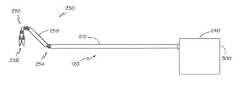
도 2는 기다란 튜브(210)에 의해서 연결된 원위부(250)와 근위 제어 메커니즘(240)을 포함하는 수술 기구(120)의 예시적인 구체예의 평면도이다. 바람직하게 수술 기구(120)는 기다란 튜브형 부재(210)에 의해 지지되는 절단 수단(256)을 제공하며, 이 부재는 수술 과정이 비교적 국한된 영역에서 착수될 수 있도록 한다. 수술 기구(120)의 원위부(250)는 바람직하게는 단부 작동기로서 전단기(256)를 제공한다. 도시된 구체예에서, 전단기(256)는 튜브형 구획(258)에 의해 연결된 2개의 관절화된 구획인 "리스트"(252)와 "조글 조인트"(254)에 의해 기다란 튜브(210)에 연결되며, 이들은 수술 도구의 위치와 방향이 조작될 수 있도록 한다.2 is a plan view of an exemplary embodiment of a
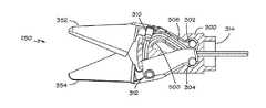
도 3 내지 6은 우회 전단 작용에 의해 절단하는 한 쌍의 수술용 전단기 또는 가위를 제공하는 수술 단부 작동기(250)의 구체예를 도시한다. 도 3은 수술 단부 작동기(250)의 측면도를 도시한다. 도 4는 수술 단부 작동기(250)의 상부도를 도시한다. 도 5는 특정한 세부내용을 더 분명히 볼 수 있도록 윗부분이 제거된 수술 단부 작동기(250)의 상부도를 도시한다. 도 6은 다른 부분의 세부내용을 더 분명히 볼 수 있도록 다른 부분이 더 제거된 수술 단부 작동기(250)의 상부도를 도시한다.Figures 3-6 illustrate an embodiment of a
수술 단부 작동기(250)는 제1 턱(352)과 제2 턱(354)을 피벗 지지하는 클레비스(300)를 포함한다. 제1 피벗(302)은 제1 턱(352)을 클레비스(300)와 연결한다. 제2 피벗(304)은 제2 턱(354)을 클레비스(300)와 연결한다. 제2 피벗(304)은 제1 피벗(302)과 이격되어 있다.The
제1 가요성 케이블 또는 와이어(306)가 케이블의 끝에서 크림핑된 제1 피팅부(310)에 의해서 제1 턱(352)에 연결된다. 제1 와이어(306)는 제2 턱(354)에 있는 안내로를 통과해 제1 피벗(302)과 제2 피벗(304) 사이를 지나 기다란 튜브(210)의 관절화된 구획에 의해 지지되는 클레비스(300)의 제1 단부(314)를 통과해서 연장된다. 제2 와이어(308)는 케이블의 끝에서 크림핑된 제2 피팅부(312)에 의해서 제2 턱(354)에 연결된다. 제1 와이어(308)는 제1 턱(352)에 있는 안내로를 통과해 제1 피벗(302)과 제2 피벗(304) 사이를 지나 클레비스(300)의 제1 단부(314)를 통과해서 연장된다. 제1 및 제2 와이어(306, 308)가 개폐력을 제공하여 제1 및 제2 턱(352, 354)을 가동시킨다.A first flexible cable or
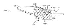
도 5 및 6에 가장 잘 도시된 대로, 안내로(500)는 와이어의 방향을 대략 90도 바꾸는 곡선 경로를 따라 와이어(308)를 안내한다. 제1 및 제2 턱(352, 354)은 각각 제1 및 제2 피벗(302, 304)에 수직인 면을 포함한다. 안내로는 홈(500)을 이 면에 포함한다. 도시된 구체예에서, 와이어는 스트랜드 형태이며, 이것은 가요성을 증가시키고 곡선 경로를 따르는 와이어의 능력을 촉진할 수 있다. 다른 구체예에서, 솔리드 와이어를 사용하여 와이어의 주어진 단면 크기에 대해 강도를 더 크게 할 수 있다.As best shown in Figures 5 and 6, the
한 구체예에서, 수술 단부 작동기는 2개의 라이너를 더 포함한다. 각 라이너는 턱 중 하나의 면에 연결되어 안내로를 형성하는 홈(500) 안에 고정된다. 이와 같이, 안내로는 라이너의 일부를 포함한다. 라이너는 와이어(306, 308)가 안내로 안을 활주할 때 마찰을 감소시킨다. 라이너는 또한 와이어(306, 308)를 이들이 관통 활주하는 턱으로부터 전기적으로 분리한다.In one embodiment, the surgical end actuator further comprises two liners. Each liner is secured in a
와이어(306, 308)의 배치는 각 와이어에 장력을 일으켜서 양쪽 턱(352, 354)에 닫힘 힘이 적용된다. 예를 들어, 장력이 제2 와이어(308)에 적용되었을 때 제2 턱(354)과의 연결부(312)가 턱을 당겨서 닫히게 된다. 동시에 제2 와이어(308)에 적용된 장력은 제2 와이어가 안내로에 의해 방향을 바꿀 때 안내로에 생기는 힘 때문에 제1 턱(352)에서 닫힘 힘을 생성할 것이다. 마찬가지로, 각 와이어에 적용되는 압축력은 양쪽 턱(352, 354)에 열림 힘을 생성한다. 이 와이어 배치에서는 더욱 컴팩트한 단부 작동기에 의해서 더 높은 열림 힘과 닫힘 힘이 생성될 수 있다.The placement of the
도 7은 본 발명을 구현한 수술 단부 작동기의 상부도를 도시한다. 도 8은 도 7의 수술 단부 작동기의 분해조립도를 도시한다.Figure 7 shows a top view of a surgical end actuator embodying the present invention. Figure 8 shows an exploded view of the surgical end actuator of Figure 7;
클레비스(700)는 기다란 튜브형 부재(210)에 의해 지지되는 제1 단부(714)를 가진다. 제1 턱(752)은 제1 선회부(804)와 제1 컷팅 엣지(806)를 포함하는 제1 작동부(802)를 가진다. 제1 피벗(702)이 제1 턱(752)을 클레비스(700)에 회전 가능하게 연결한다. 제2 턱(754)은 제2 선회부(814)와 제2 작동부(812)를 가지며, 이것은 제1 컷팅 엣지(806)를 우회하여 전단 작용을 제공하는 제2 컷팅 엣지(816)를 포함한다. 제2 피벗(704)은 제1 피벗(702)과 이격되어 있고, 제2 턱(754)을 클레비스(700)에 회전 가능하게 연결한다. 캡(800)이 제1 단부(714)의 반대쪽에서 클레비스(700)의 단부를 닫는다.The
도시된 구체예에서, 제1 및 제2 피벗(702, 704)은 클레비스(700)의 상응하는 개구 안에 압착된 원통형 핀의 형태이다. 제1 및 제2 피벗(702, 704)은 개방된 클레비스(700)의 중앙 원통 축 주변에 공간을 남기면서 이격되어 있는 2개의 평행한 회전축을 제공하며, 이로써 와이어(306, 308)가 클레비스의 해당하는 부분을 통과해 연장될 수 있다. 각 턱(752, 754)의 선회부(804, 814)에 있는 개구(832, 834)는 피벗(702, 704)에 의해서 회전 가능하게 지지된다.In the illustrated embodiment, the first and
상기 설명된 대로, 라이너(808, 818)가 각 턱(752, 754)의 선회부(804, 814)의 면에 있는 상응하는 홈에 삽입되며, 이로써 안내로를 제공할 수 있다. 와이어(도시되지 않음)가 클림핑 등에 의해 피팅부(842, 845)에 연결되고, 이것은 턱 중 하나의 상응하는 개구(843, 845)에 연결된다. 와이어는 피팅부(842, 844)로부터 나머지 턱(754, 752)에 있는 안내로를 통과해 제1 피벗(702)과 제2 피벗(704) 사이를 지나 클레비스(700)의 제1 단부(714)를 통과해서 연장된다.The
제1 컷팅 엣지(806)와 제2 컷팅 엣지(816)가 서로를 우회할 때 이들에 의해서 효과적인 전단 작용을 제공하기 위해 컷팅 엣지는 유의한 압력으로 서로에 대해 기대어져 있어야 한다. 도시된 구체예에서, 제1 스프링(852)이 제1 선회부(804)와 클레비스(700)와 연결되고, 제2 스프링(854)은 제2 선회부와 클레비스와 연결된다. 스프링(852, 854)은 때로 Belleville 와셔라고도 하는 컵 모양 스프링 와셔의 형태이다. 스프링은 선회부들이 서로 떨어지도록 강제한다. 아래 더 설명된 대로, 선회부와 작동부는 이등분 평면의 반대 측에 있다. 따라서, 선회부가 떨어지도록 강제될 때 작동부는 함께 모이도록 강제된다.When the
다른 구체예에서, 1개의 스프링을 사용하여 컷팅 엣지들을 함께 편향시킬 수 있다. 다른 구체예에서, 2개보다 많은 스프링을 사용하여 컷팅 엣지들을 함께 편향시킬 수 있다. 어떤 구체예에서, 턱들은 스프링이 선회부와 작동부를 모두 함께 강제로 모이게 하도록 구성될 수 있다.In other embodiments, one spring may be used to deflect the cutting edges together. In other embodiments, more than two springs may be used to deflect the cutting edges together. In some embodiments, the jaws may be configured to force the spring to force the swivel portion and the actuating portion together.
도시된 구체예에서, 고정 핀(850)이 클레비스(700)에 의해서 피벗 지지되고, 제1 및 제2 턱(752, 754)에 있는 상응하는 개구(856, 858)에 피벗 연결되며, 이로써 고정 핀은 제1 및 제2 턱이 반대 동작을 하도록 구속한다. 고정 핀(850)은 스프링(852, 854)의 중앙 개구(862, 864)를 통과한다.In the illustrated embodiment, the retaining
도시된 구체예에서, 각 스프링(852, 854)에 있는 탭(866, 868)이 턱(752, 754)과 맞물림으로써 스프링이 각각의 턱과 협력하여 회전하게 된다. 이 방식에서는 스프링의 모양을 턱의 인접한 면의 모양에 상응하게 함으로써 원형이 아닌 스프링을 사용하는 것이 가능하다.In the illustrated embodiment, the
도 9는 제1 단부의 반대쪽에서 캡에 의해 닫힌 단부로부터 본 클레비스(700)의 도면이다. 2개의 스프링 와셔(852, 854)와 클레비스(700)의 관계를 이 도면에서 더 분명히 볼 수 있다. 고정 핀(850)과 클레비스(700)의 관계 또한 이 도면에서 더 분명히 볼 수 있다.9 is a view of the
도 10은 클레비스가 없는 2개 턱(752, 754)의 측면도이다. 도 11은 클레비스가 없는 1개의 턱(752)의 측면도이다. 점선 라인(1000)으로 제시된 대로, 선회부(804, 814)는 피벗(702, 704)의 회전축에 수직인 이등분 평면의 제1 측에 있고, 작동부(802, 812)는 이등분 평면의 반대 측에 있다.10 is a side view of two
구체적으로 도 11을 보면, 제1 턱(752)의 선회부(804)가 이등분 평면 아래에 있으며, 이등분 평면은 도면 페이지와 수직이며 이등분 평면과 교차하고, 도면 페이지는 점선 라인(1000)으로 제시된다. 제1 턱(752)의 작동부(802)는 이등분 평면 위에 있다. 제1 턱(752)의 연결부(1100)가 이등분 평면을 통과하여 선회부(804)와 작동부(802)를 잇는다. 턱들의 이런 크로스오버 구조는 스프링의 편향력이 이등분 평면에 인접하여 적용될 수 있도록 한다.11, the
이등분 평면에 인접하여 편향력을 적용하는 것은 이용가능한 공간을 제한하는 클레비스의 작은 크기 및 원통 모양 때문에 유익할 수 있다. 이등분 평면에 인접하여 편향력을 적용하면 2개의 턱(752, 754)의 작동부(802, 812)가 서로를 향해서 강제로 모이게 되고, 부분(804, 814)들은 서로로부터 멀어지면서 선회된다. 클레비스(700)는 피벗(702, 704)에서 내부를 향한 반응력을 제공하며, 이것은 2개의 턱(752, 754)의 선회부(804, 814)에 적용되는 외부를 향하는 힘을 상쇄한다. 피벗(702, 704)에 인접한 클레비스의 제1 단부(714)는 휨 없이 내부를 향한 반응력을 제공할 수 있는 강도 및 강직성을 지닌 완전한 원통형 구조를 제공한다. 2개의 턱(752, 754)을 수용할 수 있도록 클레비스의 일부가 절단되어 있는 캡(800)에 인접한 클레비스의 더 얇은 구조는 편향 스프링(852, 854)으로부터 휨 힘을 받지 않는다.Applying the biasing force adjacent the bisector plane may be beneficial because of the small size of the clevis and the cylindrical shape that limits the available space. Applying a biasing force adjacent the bisector plane forces the actuating
특정한 예시적인 구체예들이 설명되고 첨부한 도면에 도시되었지만, 이러한 구체예들은 넓은 범위의 발명의 단지 예시일 뿐이며 제한이 아니라는 것과 본 발명이 도시되고 설명된 특정한 구성 및 배치에 제한되지 않으며, 당업자는 다양한 다른 변형을 만들 수 있다는 것이 이해되어야 한다. 따라서, 본 설명은 제한이 아니라 예시라고 생각되어야 한다.
While certain exemplary embodiments have been described and shown in the accompanying drawings, it is to be understood that these embodiments are merely illustrative of, and not limiting, the broad inventions, and that the invention is not limited to the specific constructions and arrangements shown and described, It should be understood that various other variations can be made. Accordingly, the description is to be regarded as illustrative rather than limiting.
Claims (40)
Translated fromKorean제1 선회부와 제1 작동부를 가진 제1 턱;
제1 선회부를 클레비스에 회전 가능하게 연결하는 제1 피벗으로서, 제1 피벗 축을 중심으로 회전하는 제1 피벗;
제2 선회부와 제2 작동부를 가진 제2 턱; 및
제2 선회부를 클레비스에 회전 가능하게 연결하는 제2 피벗으로서, 제2 피벗 축을 중심으로 회전하는 제2 피벗;을 포함하며,
제2 피벗 축은 제1 피벗 축으로부터 이격되어서, 제1 선회부는 제2 피벗 축에 수직인 이등분 평면의 제1 측에 있고, 제2 선회부는 제1 측에 반대쪽인 이등분 평면의 제2 측에 있고, 제1 작동부는 이등분 평면의 제2 측에 있고, 제2 작동부는 이등분 평면의 제1 측에 있는 수술 단부 작동기.Clevis;
A first jaw having a first turning part and a first actuating part;
A first pivot rotatably connecting the first pivot portion to the clevis, the first pivot rotatably about a first pivot axis;
A second jaw having a second turning part and a second actuating part; And
A second pivot rotatably connecting the second pivot portion to the clevis, the second pivot rotating about a second pivot axis,
The second pivot axis is spaced from the first pivot axis such that the first pivot portion is on a first side of a bisector plane perpendicular to the second pivot axis and the second pivot portion is on a second side of a bisector plane opposite the first side The first actuating part is on the second side of the bisector plane and the second actuating part is on the first side of the bisector plane.
제1 선회부와 제1 작동부를 가진 제1 턱을 제공하는 단계;
제1 피벗 축을 중심으로 회전하는 제1 피벗을 사용해서 제1 선회부를 클레비스에 회전 가능하게 연결하는 단계;
제2 선회부와 제2 작동부를 가진 제2 턱을 제공하는 단계; 및
제1 피벗 축으로부터 이격된 제2 피벗 축을 중심으로 회전하는 제2 피벗을 사용해서 제2 선회부를 클레비스에 회전 가능하게 연결하는 단계;를 포함하며, 이로써 제1 선회부는 제2 피벗 축에 수직인 이등분 평면의 제1 측에 위치되고, 제2 선회부는 제1 측에 반대쪽인 이등분 평면의 제2 측에 위치되고, 제1 작동부는 이등분 평면의 제2 측에 위치되고, 제2 작동부는 이등분 평면의 제1 측에 위치되는 수술 단부 작동기를 제조하는 방법.Providing clevis;
Providing a first jaw having a first pivot portion and a first actuating portion;
Rotatably coupling the first pivot portion to the clevis using a first pivot rotating about a first pivot axis;
Providing a second jaw having a second turning portion and a second actuating portion; And
Rotatably coupling the second pivot portion to the clevis using a second pivot that rotates about a second pivot axis spaced from the first pivot axis, whereby the first pivot portion is perpendicular to the second pivot axis And the second actuating portion is located on the second side of the bisector plane and the second actuating portion is located on the second side of the bisector plane which is opposite to the first side, RTI ID = 0.0 > 1, < / RTI >
클레비스에 고정 핀을 피벗 지지하는 단계;
고정 핀을 제1 스프링의 중앙 개구를 통과시키는 단계; 및
고정 핀을 제1 및 제2 턱에 피벗 연결하는 단계
를 더 포함하며, 이로써 고정 핀이 제1 턱과 제2 턱이 반대 동작하도록 구속하는 것을 특징으로 하는 방법.18. The method of claim 17,
Pivotally supporting the fixation pin on the clevis;
Passing the fixing pin through a central opening of the first spring; And
Pivotally connecting the fixing pin to the first and second jaws
Whereby the fastening pin restrains the first jaw and the second jaw to operate in opposite directions.
제1 선회부와, 제1 컷팅 엣지를 포함하는 제1 작동부를 가진 제1 턱;
제1 턱을 클레비스에 회전 가능하게 연결하고 제1 피벗 축을 중심으로 회전하는 제1 피벗;
제2 선회부와, 제1 컷팅 엣지를 우회하여 전단 작용을 제공하는 제2 컷팅 엣지를 포함하는 제2 작동부를 가진 제2 턱; 및
제2 턱을 클레비스에 회전 가능하게 연결하고 제1 피벗 축으로부터 이격된 제2 피벗 축을 중심으로 회전하는 제2 피벗;을 포함하는 수술 단부 작동기.Clevis;
A first jaw having a first pivot portion and a first actuating portion including a first cutting edge;
A first pivot rotatably connecting the first jaw to the clevis and rotating about a first pivot axis;
A second jaw having a second pivoting portion and a second actuating portion including a second cutting edge that bypasses the first cutting edge to provide a shearing action; And
And a second pivot rotatably connecting the second jaw to the clevis and rotating about a second pivot axis spaced from the first pivot axis.
제1 선회부와, 제1 컷팅 엣지를 포함하는 제1 작동부를 가진 제1 턱을 제공하는 단계;
제1 피벗 축을 중심으로 회전하는 제1 피벗을 사용해서 제1 턱을 클레비스에 회전 가능하게 연결하는 단계;
제2 선회부와, 제1 컷팅 엣지를 우회하여 전단 작용을 제공하는 제2 컷팅 엣지를 포함하는 제2 작동부를 가진 제2 턱을 제공하는 단계; 및
제1 피벗 축으로부터 이격된 제2 피벗 축을 중심으로 회전하는 제2 피벗을 사용해서 제2 턱을 클레비스에 회전 가능하게 연결하는 단계;를 포함하는 수술 단부 작동기를 제조하는 방법.Providing clevis;
Providing a first jaw having a first pivot portion and a first actuating portion including a first cutting edge;
Rotatably coupling the first jaw to the clevis using a first pivot rotating about a first pivot axis;
Providing a second jaw having a second pivot portion and a second actuating portion including a second cutting edge bypassing the first cutting edge to provide a shearing action; And
Rotatably connecting the second jaw to the clevis using a second pivot rotating about a second pivot axis spaced from the first pivot axis.
클레비스에 고정 핀을 피벗 지지하는 단계;
고정 핀을 제1 스프링의 중앙 개구를 통과시키는 단계; 및
고정 핀을 제1 및 제2 턱에 피벗 연결하는 단계
를 더 포함하며, 이로써 고정 핀이 제1 턱과 제2 턱이 반대 동작하도록 구속하는 것을 특징으로 하는 방법.39. The method of claim 38,
Pivotally supporting the fixation pin on the clevis;
Passing the fixing pin through a central opening of the first spring; And
Pivotally connecting the fixing pin to the first and second jaws
Whereby the fastening pin restrains the first jaw and the second jaw to operate in opposite directions.
36. The method of claim 35, further comprising coupling the first spring to the first pivot portion and the clevis, and coupling the second spring to the second pivot portion and the clevis, To a second position.
Applications Claiming Priority (5)
| Application Number | Priority Date | Filing Date | Title |
|---|---|---|---|
| US35655110P | 2010-06-18 | 2010-06-18 | |
| US61/356,551 | 2010-06-18 | ||
| US12/910,634US9456839B2 (en) | 2010-06-18 | 2010-10-22 | Scissor bias for direct pull surgical instrument |
| US12/910,634 | 2010-10-22 | ||
| PCT/US2011/039067WO2011159493A1 (en) | 2010-06-18 | 2011-06-03 | Scissor bias for direct pull surgical instrument |
Related Child Applications (1)
| Application Number | Title | Priority Date | Filing Date |
|---|---|---|---|
| KR1020187009281ADivisionKR101925398B1 (en) | 2010-06-18 | 2011-06-03 | Scissor bias for direct pull surgical instrument |
Publications (2)
| Publication Number | Publication Date |
|---|---|
| KR20130109013A KR20130109013A (en) | 2013-10-07 |
| KR101846440B1true KR101846440B1 (en) | 2018-04-06 |
Family
ID=44627311
Family Applications (2)
| Application Number | Title | Priority Date | Filing Date |
|---|---|---|---|
| KR1020127033609AActiveKR101846440B1 (en) | 2010-06-18 | 2011-06-03 | Scissor bias for direct pull surgical instrument |
| KR1020187009281AActiveKR101925398B1 (en) | 2010-06-18 | 2011-06-03 | Scissor bias for direct pull surgical instrument |
Family Applications After (1)
| Application Number | Title | Priority Date | Filing Date |
|---|---|---|---|
| KR1020187009281AActiveKR101925398B1 (en) | 2010-06-18 | 2011-06-03 | Scissor bias for direct pull surgical instrument |
Country Status (5)
| Country | Link |
|---|---|
| US (1) | US9456839B2 (en) |
| EP (1) | EP2582308B1 (en) |
| KR (2) | KR101846440B1 (en) |
| CN (1) | CN103037787B (en) |
| WO (1) | WO2011159493A1 (en) |
Families Citing this family (34)
| Publication number | Priority date | Publication date | Assignee | Title |
|---|---|---|---|---|
| US9339341B2 (en) | 2010-02-08 | 2016-05-17 | Intuitive Surgical Operations, Inc. | Direct pull surgical gripper |
| CN103142290B (en)* | 2012-11-07 | 2015-05-06 | 苏州天臣国际医疗科技有限公司 | Medical amputation device and cutting anastomat applying same |
| US10932867B2 (en) | 2013-08-15 | 2021-03-02 | Intuitive Surgical Operations, Inc. | Reusable surgical instrument with single-use tip and integrated tip cover |
| DE102013220019A1 (en)* | 2013-10-02 | 2015-04-02 | Richard Wolf Gmbh | Instrument, in particular a medical endoscopic instrument or technoscope |
| CN106102632B (en) | 2014-03-17 | 2019-06-14 | 直观外科手术操作公司 | Fix instrument control input bearing/orientation during in-program restart |
| JP6322516B2 (en)* | 2014-08-01 | 2018-05-09 | 株式会社高山医療機械製作所 | Tweezers for precision work including medical use |
| ITUB20154977A1 (en) | 2015-10-16 | 2017-04-16 | Medical Microinstruments S R L | Medical instrument and method of manufacture of said medical instrument |
| WO2017151850A1 (en)* | 2016-03-03 | 2017-09-08 | Covidien Lp | Input device handle for robotic surgical systems capable of large rotations about a roll axis |
| DE102016111001A1 (en)* | 2016-06-16 | 2017-12-21 | Aesculap Ag | Surgical instrument with spacing pivot element |
| USD846127S1 (en)* | 2016-06-20 | 2019-04-16 | Imperial Innovations Limited | Surgical robot |
| DE102016220286A1 (en)* | 2016-09-20 | 2018-03-22 | Epflex Feinwerktechnik Gmbh | Tubular shaft instrument with distal, rotatable functional part |
| DE112016007267T5 (en)* | 2016-11-21 | 2019-06-13 | Olympus Corporation | pliers scissors |
| EP3654869A1 (en)* | 2017-07-17 | 2020-05-27 | Medrobotics Corporation | Surgical tools |
| CN109984777B (en)* | 2017-12-29 | 2022-02-08 | 江苏木偶医疗科技有限公司 | Drive structure and device with flexible joint |
| WO2019199827A1 (en) | 2018-04-10 | 2019-10-17 | Intuitive Surgical Operations, Inc. | Articulable medical devices having flexible wire routing |
| CN109009455A (en)* | 2018-07-13 | 2018-12-18 | 深圳市精锋医疗科技有限公司 | Replaceable end instrument from operation equipment |
| CN109009456A (en)* | 2018-07-13 | 2018-12-18 | 深圳市精锋医疗科技有限公司 | The motion arm of replaceable end instrument |
| CN109009454A (en)* | 2018-07-13 | 2018-12-18 | 深圳市精锋医疗科技有限公司 | Detachable end instrument from operation equipment |
| US11259798B2 (en) | 2018-07-16 | 2022-03-01 | Intuitive Surgical Operations, Inc. | Medical devices having tissue grasping surfaces and features for manipulating surgical needles |
| US11612447B2 (en) | 2018-07-19 | 2023-03-28 | Intuitive Surgical Operations, Inc. | Medical devices having three tool members |
| US11576738B2 (en) | 2018-10-08 | 2023-02-14 | Auris Health, Inc. | Systems and instruments for tissue sealing |
| US11291514B2 (en) | 2018-11-15 | 2022-04-05 | Intuitive Surgical Operations, Inc. | Medical devices having multiple blades and methods of use |
| US11213287B2 (en) | 2018-11-15 | 2022-01-04 | Intuitive Surgical Operations, Inc. | Support apparatus for a medical retractor device |
| LU101444B1 (en)* | 2019-10-15 | 2021-04-15 | G Hipp & Sohn Gmbh | Surgical instrument |
| GB2600144B (en)* | 2020-10-23 | 2024-10-30 | Cmr Surgical Ltd | Arrangement for a bladed surgical instrument |
| LU102168B1 (en)* | 2020-10-26 | 2022-04-27 | G Hipp & Sohn Gmbh | surgical instrument |
| US11406060B1 (en)* | 2021-02-04 | 2022-08-09 | Tortuga Agricultural Technologies, Inc. | End effector for harvesting |
| CN112914683B (en)* | 2021-03-10 | 2022-09-27 | 山东威高手术机器人有限公司 | Multi-degree-of-freedom surgical instrument with independently moving forceps leaves and end effector |
| TWI838986B (en) | 2021-11-30 | 2024-04-11 | 美商安督奎斯特機器人公司 | Patient console, robotic surgical system having the same, and method for performing the same |
| EP4440481A1 (en) | 2021-11-30 | 2024-10-09 | Endoquest Robotics, Inc. | Barrier drape adapters for robotic surgical systems |
| WO2023101974A1 (en) | 2021-11-30 | 2023-06-08 | Endoquest Robotics, Inc. | Force transmission systems for robotically controlled medical devices |
| WO2023101948A1 (en) | 2021-11-30 | 2023-06-08 | Endoquest, Inc. | Master control systems for robotic surgical systems |
| TWI835436B (en) | 2021-11-30 | 2024-03-11 | 美商安督奎斯特機器人公司 | Steerable overtube assemblies for robotic surgical systems, control assemblies and method thereof |
| TWI850880B (en) | 2021-11-30 | 2024-08-01 | 美商安督奎斯特機器人公司 | Disposable end effectors, medical device, and operating method thereof |
Citations (1)
| Publication number | Priority date | Publication date | Assignee | Title |
|---|---|---|---|---|
| US6206903B1 (en) | 1999-10-08 | 2001-03-27 | Intuitive Surgical, Inc. | Surgical tool with mechanical advantage |
Family Cites Families (13)
| Publication number | Priority date | Publication date | Assignee | Title |
|---|---|---|---|---|
| US2592484A (en) | 1946-06-15 | 1952-04-08 | Moreton A Smith | Power-driven tweezer |
| EP0513471A3 (en)* | 1991-04-19 | 1993-02-03 | Lutz Kothe | Surgical instrument |
| US5312434A (en)* | 1992-12-21 | 1994-05-17 | Lawrence Crainich | Medical instrument |
| GB9309142D0 (en) | 1993-05-04 | 1993-06-16 | Gyrus Medical Ltd | Laparoscopic instrument |
| US5792165A (en) | 1993-07-21 | 1998-08-11 | Charles H. Klieman | Endoscopic instrument with detachable end effector |
| US5575805A (en) | 1994-10-07 | 1996-11-19 | Li Medical Technologies, Inc. | Variable tip-pressure surgical grasper |
| CN1163558A (en) | 1994-10-11 | 1997-10-29 | 查尔斯·H·克利曼 | Endoscopic instrument with detachable end effector |
| US6168605B1 (en) | 1999-07-08 | 2001-01-02 | Ethicon Endo-Surgery, Inc. | Curved laparoscopic scissor having arcs of curvature |
| US6840938B1 (en)* | 2000-12-29 | 2005-01-11 | Intuitive Surgical, Inc. | Bipolar cauterizing instrument |
| DE102006028001B4 (en) | 2006-06-14 | 2009-11-26 | Paul Peschke Gmbh | Surgical grasping forceps |
| US7648519B2 (en) | 2006-09-13 | 2010-01-19 | Cambridge Endoscopic Devices, Inc. | Surgical instrument |
| US8277475B2 (en) | 2008-05-09 | 2012-10-02 | Applied Medical Resources Corporation | Laparoscopic scissors |
| US20110144678A1 (en)* | 2009-12-15 | 2011-06-16 | Slater Charles R | Endoscopic Scissors Instrument |
- 2010
- 2010-10-22USUS12/910,634patent/US9456839B2/enactiveActive
- 2011
- 2011-06-03KRKR1020127033609Apatent/KR101846440B1/enactiveActive
- 2011-06-03KRKR1020187009281Apatent/KR101925398B1/enactiveActive
- 2011-06-03EPEP11727038.9Apatent/EP2582308B1/enactiveActive
- 2011-06-03WOPCT/US2011/039067patent/WO2011159493A1/enactiveApplication Filing
- 2011-06-03CNCN201180029424.5Apatent/CN103037787B/enactiveActive
Patent Citations (1)
| Publication number | Priority date | Publication date | Assignee | Title |
|---|---|---|---|---|
| US6206903B1 (en) | 1999-10-08 | 2001-03-27 | Intuitive Surgical, Inc. | Surgical tool with mechanical advantage |
Also Published As
| Publication number | Publication date |
|---|---|
| CN103037787B (en) | 2016-04-06 |
| US9456839B2 (en) | 2016-10-04 |
| KR101925398B1 (en) | 2018-12-05 |
| US20110313449A1 (en) | 2011-12-22 |
| WO2011159493A1 (en) | 2011-12-22 |
| EP2582308B1 (en) | 2017-11-01 |
| EP2582308A1 (en) | 2013-04-24 |
| KR20130109013A (en) | 2013-10-07 |
| CN103037787A (en) | 2013-04-10 |
| KR20180039733A (en) | 2018-04-18 |
Similar Documents
| Publication | Publication Date | Title |
|---|---|---|
| KR101846440B1 (en) | Scissor bias for direct pull surgical instrument | |
| US12137926B2 (en) | Direct pull surgical gripper | |
| US10980556B2 (en) | Rotary input for lever actuation | |
| EP3373838B1 (en) | Reconfigurable end effector architecture | |
| US9333045B2 (en) | Method and means for transferring controller motion from a robotic manipulator to an attached instrument | |
| US12251088B2 (en) | Low-friction, small profile medical tools having easy-to-assemble components | |
| US8661927B2 (en) | Cable re-ordering device | |
| US8991278B2 (en) | Overforce protection mechanism | |
| US12082900B2 (en) | Low-friction, small profile medical tools having easy-to-assemble components |
Legal Events
| Date | Code | Title | Description |
|---|---|---|---|
| PA0105 | International application | Patent event date:20121224 Patent event code:PA01051R01D Comment text:International Patent Application | |
| PG1501 | Laying open of application | ||
| A201 | Request for examination | ||
| PA0201 | Request for examination | Patent event code:PA02012R01D Patent event date:20160601 Comment text:Request for Examination of Application | |
| E902 | Notification of reason for refusal | ||
| PE0902 | Notice of grounds for rejection | Comment text:Notification of reason for refusal Patent event date:20170512 Patent event code:PE09021S01D | |
| E701 | Decision to grant or registration of patent right | ||
| PE0701 | Decision of registration | Patent event code:PE07011S01D Comment text:Decision to Grant Registration Patent event date:20171226 | |
| A107 | Divisional application of patent | ||
| GRNT | Written decision to grant | ||
| PA0104 | Divisional application for international application | Comment text:Divisional Application for International Patent Patent event code:PA01041R01D Patent event date:20180402 | |
| PR0701 | Registration of establishment | Comment text:Registration of Establishment Patent event date:20180402 Patent event code:PR07011E01D | |
| PR1002 | Payment of registration fee | Payment date:20180403 End annual number:3 Start annual number:1 | |
| PG1601 | Publication of registration | ||
| PR1001 | Payment of annual fee | Payment date:20210330 Start annual number:4 End annual number:4 | |
| PR1001 | Payment of annual fee | Payment date:20230323 Start annual number:6 End annual number:6 |