KR101846409B1 - Backlight unit - Google Patents
Backlight unitDownload PDFInfo
- Publication number
- KR101846409B1 KR101846409B1KR1020110071291AKR20110071291AKR101846409B1KR 101846409 B1KR101846409 B1KR 101846409B1KR 1020110071291 AKR1020110071291 AKR 1020110071291AKR 20110071291 AKR20110071291 AKR 20110071291AKR 101846409 B1KR101846409 B1KR 101846409B1
- Authority
- KR
- South Korea
- Prior art keywords
- light
- guide plate
- light guide
- light source
- composite sheet
- Prior art date
- Legal status (The legal status is an assumption and is not a legal conclusion. Google has not performed a legal analysis and makes no representation as to the accuracy of the status listed.)
- Active
Links
Images


Classifications
- G—PHYSICS
- G02—OPTICS
- G02F—OPTICAL DEVICES OR ARRANGEMENTS FOR THE CONTROL OF LIGHT BY MODIFICATION OF THE OPTICAL PROPERTIES OF THE MEDIA OF THE ELEMENTS INVOLVED THEREIN; NON-LINEAR OPTICS; FREQUENCY-CHANGING OF LIGHT; OPTICAL LOGIC ELEMENTS; OPTICAL ANALOGUE/DIGITAL CONVERTERS
- G02F1/00—Devices or arrangements for the control of the intensity, colour, phase, polarisation or direction of light arriving from an independent light source, e.g. switching, gating or modulating; Non-linear optics
- G02F1/01—Devices or arrangements for the control of the intensity, colour, phase, polarisation or direction of light arriving from an independent light source, e.g. switching, gating or modulating; Non-linear optics for the control of the intensity, phase, polarisation or colour
- G02F1/13—Devices or arrangements for the control of the intensity, colour, phase, polarisation or direction of light arriving from an independent light source, e.g. switching, gating or modulating; Non-linear optics for the control of the intensity, phase, polarisation or colour based on liquid crystals, e.g. single liquid crystal display cells
- G02F1/133—Constructional arrangements; Operation of liquid crystal cells; Circuit arrangements
- G02F1/1333—Constructional arrangements; Manufacturing methods
- G02F1/1335—Structural association of cells with optical devices, e.g. polarisers or reflectors
- G02F1/1336—Illuminating devices
- G02F1/133615—Edge-illuminating devices, i.e. illuminating from the side
- G—PHYSICS
- G02—OPTICS
- G02B—OPTICAL ELEMENTS, SYSTEMS OR APPARATUS
- G02B6/00—Light guides; Structural details of arrangements comprising light guides and other optical elements, e.g. couplings
- G02B6/0001—Light guides; Structural details of arrangements comprising light guides and other optical elements, e.g. couplings specially adapted for lighting devices or systems
- G02B6/0011—Light guides; Structural details of arrangements comprising light guides and other optical elements, e.g. couplings specially adapted for lighting devices or systems the light guides being planar or of plate-like form
- G02B6/0013—Means for improving the coupling-in of light from the light source into the light guide
- G02B6/0023—Means for improving the coupling-in of light from the light source into the light guide provided by one optical element, or plurality thereof, placed between the light guide and the light source, or around the light source
- G02B6/0025—Diffusing sheet or layer; Prismatic sheet or layer
- G—PHYSICS
- G02—OPTICS
- G02B—OPTICAL ELEMENTS, SYSTEMS OR APPARATUS
- G02B6/00—Light guides; Structural details of arrangements comprising light guides and other optical elements, e.g. couplings
- G02B6/0001—Light guides; Structural details of arrangements comprising light guides and other optical elements, e.g. couplings specially adapted for lighting devices or systems
- G02B6/0011—Light guides; Structural details of arrangements comprising light guides and other optical elements, e.g. couplings specially adapted for lighting devices or systems the light guides being planar or of plate-like form
- G02B6/0033—Means for improving the coupling-out of light from the light guide
- G02B6/0035—Means for improving the coupling-out of light from the light guide provided on the surface of the light guide or in the bulk of it
- G02B6/0036—2-D arrangement of prisms, protrusions, indentations or roughened surfaces
- G—PHYSICS
- G02—OPTICS
- G02B—OPTICAL ELEMENTS, SYSTEMS OR APPARATUS
- G02B6/00—Light guides; Structural details of arrangements comprising light guides and other optical elements, e.g. couplings
- G02B6/0001—Light guides; Structural details of arrangements comprising light guides and other optical elements, e.g. couplings specially adapted for lighting devices or systems
- G02B6/0011—Light guides; Structural details of arrangements comprising light guides and other optical elements, e.g. couplings specially adapted for lighting devices or systems the light guides being planar or of plate-like form
- G02B6/0066—Light guides; Structural details of arrangements comprising light guides and other optical elements, e.g. couplings specially adapted for lighting devices or systems the light guides being planar or of plate-like form characterised by the light source being coupled to the light guide
- G02B6/0073—Light emitting diode [LED]
Landscapes
- Physics & Mathematics (AREA)
- General Physics & Mathematics (AREA)
- Optics & Photonics (AREA)
- Nonlinear Science (AREA)
- Mathematical Physics (AREA)
- Chemical & Material Sciences (AREA)
- Crystallography & Structural Chemistry (AREA)
- Engineering & Computer Science (AREA)
- Microelectronics & Electronic Packaging (AREA)
- Planar Illumination Modules (AREA)
Abstract
Translated fromKoreanDescription
Translated fromKorean본 발명은 광 효율을 높일 수 있는 백라이트 유닛에 관한 것이다.The present invention relates to a backlight unit capable of increasing light efficiency.
일반적으로 액정 표시장치(Liquid Crystal Display)는 전계를 이용하여 유전 이방성을 갖는 액정의 광 투과율을 조절함으로써 화상을 표시하게 된다. 이를 위해, 액정 표시장치는 액정 셀들이 매트릭스형으로 배열된 액정패널과, 액정패널을 구동하기 위한 구동회로와, 액정패널에 광을 조사하는 백라이트 유닛을 포함한다.2. Description of the Related Art In general, a liquid crystal display displays an image by adjusting the light transmittance of a liquid crystal having dielectric anisotropy using an electric field. To this end, the liquid crystal display device includes a liquid crystal panel in which liquid crystal cells are arranged in a matrix, a driving circuit for driving the liquid crystal panel, and a backlight unit for irradiating the liquid crystal panel with light.
이하, 첨부한 도면을 참고하여 종래기술에 따른 백라이트 유닛에 대해 설명한다.Hereinafter, a backlight unit according to the related art will be described with reference to the accompanying drawings.
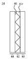
도 1은 종래의 백라이트 유닛의 개략적인 단면도이며, 에지 방식의 백라이트 유닛에 관한 것이다.1 is a schematic cross-sectional view of a conventional backlight unit and relates to an edge type backlight unit.
도 1에 도시된 백라이트 유닛은 광원(2), 도광판(4), 반사판(6) 및 다수의 광학시트(8)를 포함한다.The backlight unit shown in Fig. 1 includes a
광원(2)은 도광판(4)의 측면에 배치되어 광을 방출한다. 이러한 광원(2)은 EL(Electro Luminescence), 발광 다이오드(Light Emitting Diode), 냉음극 형광램프(CCFL: Cold Cathode Fluorescent Lamp) 및 열음극 형광램프(HCFL: Hot Cathode Fluorescent Lamp) 중에서 어느 하나가 될 수 있다.The
도광판(4)은 광원(2)에서 방출된 광을 입사면을 통해 제공받는데, 입사된 광을 입사면의 반대쪽 방향으로 전달함과 동시에 입사된 광을 액정패널 쪽으로 안내하는 역할을 한다.The
반사판(6)은 도광판(4)의 하부에 배치되어 도광판(4)에서 하부로 출사된 광을 상부로 반사시킨다.The
다수의 광학시트(8)는 도광판(4)의 상부에 배치된 적어도 하나의 확산시트 및 프리즘 시트를 포함한다. 확산시트는 도광판(4)에서 상부로 출사된 광을 전면으로 확산시킨다. 프리즘 시트는 확산시트에 의해 확산된 광을 집광한다.The plurality of
한편, 도광판(4)은 백라이트 유닛 구동시 발생된 열에 의해 팽창을 하게 되는데, 도광판(4)의 팽창시 도광판(4)과 광원(2)이 충돌하여 광원(2)이 손상될 우려가 있다. 이를 방지하기 위해, 도광판(4)과 광원(2)은 소정간격 이격되도록 설계된다.On the other hand, the
이와 같이, 종래기술에 따른 백라이트 유닛은 광원(2)과 도광판(4)이 소정간격 이격되어 에어 갭(Air Gap)을 형성하는데, 이 에어 갭으로 인해 백라이트 유닛의 광 효율이 저하되는 문제점이 있다.As described above, in the backlight unit according to the related art, the
구체적으로, 스넬의 법칙에 따르면 광은 매질이 바뀌면 굴절하게 되는데, 이는 매질의 굴절율이 변하기 때문이다. 따라서, 광은 광원(2)의 내부에서 외부 공기(Air)로 방출되는 과정에서 굴절되며, 외부 공기에서 도광판(4)에 입사되는 과정에서 다시 굴절된다. 이러한 광의 굴절은 광 손실을 초래하는데, 광원(2)에서 발생된 광 중 일부가 외부 공기로 방출되지 못하고 광원(2) 내부에서 전반사되어 손실되며, 외부 공기에 방출된 광 중 일부가 도광판(2)에 입사되지 못하고 도광판(2)의 입사면에서 전반사되어 손실된다. 즉, 백라이트 유닛의 광 효율 저하는 광원(2)과 공기의 굴절율 차이와, 공기와 도광판(4)의 굴절율 차이로 인해 발생된다.Specifically, according to Snell's law, light is refracted when the medium is changed, because the refractive index of the medium is changed. Accordingly, the light is refracted in the process of being emitted from the inside of the
본 발명은 상기와 같은 문제점을 해결하기 위한 것으로, 광 효율을 높일 수 있는 백라이트 유닛을 제공하는데 그 목적이 있다.SUMMARY OF THE INVENTION It is an object of the present invention to provide a backlight unit capable of increasing light efficiency.
상기와 같은 목적을 달성하기 위해 본 발명의 실시 예에 따른 백라이트 유닛은 입사면을 통해 광을 제공받는 도광판과; 상기 도광판의 적어도 한 측면에 배치되어 광을 방출하는 광원; 및 상기 광원과 상기 도광판 사이의 에어 갭(Air Gap)이 삭제되도록 상기 광원과 상기 도광판 사이에 배치되어 양면 각각이 상기 광원 및 상기 도광판의 입사면에 부착되는 복합시트를 포함하고; 상기 복합시트는 상기 광원에 부착되는 제 1 층과, 상기 입사면에 부착되는 제 3 층, 및 다수의 프리즘 산을 포함하며 상기 제 1 층 및 상기 제 3 층 사이에 형성되는 제 2 층을 포함하고; 상기 다수의 프리즘 산은 상기 입사면 방향으로 돌출되며 능선의 진행방향이 상기 입사면의 길이방향과 나란하게 형성되는 것을 특징으로 한다.In order to achieve the above object, a backlight unit according to an embodiment of the present invention includes a light guide plate that receives light through an incident surface; A light source disposed on at least one side surface of the light guide plate to emit light; And a composite sheet disposed between the light source and the light guide plate such that an air gap between the light source and the light guide plate is eliminated, and both sides of the composite sheet are attached to the light source and the incident surface of the light guide plate; The composite sheet includes a first layer attached to the light source, a third layer attached to the entrance surface, and a second layer comprising a plurality of prism mountains and formed between the first and third layers and; The plurality of prism mountains protrude in the direction of the incident surface and the traveling direction of the ridgeline is formed to be parallel to the longitudinal direction of the incident surface.
상기 광원은 인쇄회로기판에 설치되는 리드 프레임과; 상기 리드 프레임 내부에 배치된 발광 다이오드 칩; 및 상기 리드 프레임 내부에 충진되어 상기 발광 다이오드 칩을 보호하며 형광체가 혼합된 몰딩을 포함하는 다수의 발광 다이오드 패키지로 이루어진 것을 특징으로 한다.The light source includes a lead frame mounted on a printed circuit board; A light emitting diode chip disposed inside the lead frame; And a plurality of light emitting diode packages which are filled in the lead frame to protect the light emitting diode chip and include a molding in which phosphors are mixed.
상기 복합시트의 재질은 상기 몰딩의 굴절율과 상기 도광판의 굴절율 사이의 굴절율을 갖는 것을 특징으로 한다.And the material of the composite sheet has a refractive index between a refractive index of the molding and a refractive index of the light guide plate.
상기 복합시트의 재질은 1.40 ~ 1.55 의 굴절율을 갖는 것을 특징으로 한다.And the material of the composite sheet has a refractive index of 1.40 to 1.55.
상기 발광 다이오드 칩은 청색 광, 적색 광, 녹색 광, 백색 광 중에서 선택된 어느 하나의 광을 발생하는 것을 특징으로 한다.The light emitting diode chip generates any one of blue light, red light, green light, and white light.
상기 복합시트의 재질은 50 ~ 70 범위의 쇼어 경도를 갖는 것을 특징으로 한다.And the material of the composite sheet has a Shore hardness in the range of 50 to 70. [
상기 제 1 층 및 상기 제 3 층 각각은 0.3 ~ 1 mm 의 두께를 갖는 것을 특징으로 한다.And each of the first layer and the third layer has a thickness of 0.3 to 1 mm.
상기 다수의 프리즘 산들 사이에는 공기가 충진되는 것을 특징으로 한다.And air is filled between the plurality of prism mountains.
본 발명에 따른 백라이트 유닛은 광원과 도광판 사이에 양면 각각이 광원과 도광판에 부착되는 복합시트를 구비한다. 복합시트는 양면이 점착력을 가지므로 도광판과 광원에 간단히 부착되어 조립공정이 유리해지며, 도광판의 열팽창으로 인한 도광판과 광원의 충격방지 효과가 있다. 또한, 복합시트는 광원에서 발생된 열을 방출하는 방열 효과가 있다. 또한, 복합시트의 재질은 몰딩의 굴절율과 도광판의 굴절율 사이의 굴절을 가짐으로써 백라이트 유닛의 광 효율을 높일 수 있다. 그리고 복합시트는 다수의 프리즘 산을 구비하여 도광판의 입광부 주변에서 휘선 불량을 방지할 수 있다.A backlight unit according to the present invention includes a composite sheet on both sides between a light source and a light guide plate attached to a light source and a light guide plate. Since the composite sheet has an adhesive force on both sides, it is easily adhered to the light guide plate and the light source, and the assembling process is advantageous, and the light guide plate and the light source are prevented from being impacted due to thermal expansion of the light guide plate. Further, the composite sheet has a heat radiating effect for emitting heat generated in the light source. Further, the material of the composite sheet has a refractive index between the refractive index of the molding and the refractive index of the light guide plate, thereby increasing the light efficiency of the backlight unit. The composite sheet is provided with a plurality of prism mountains so that a bright line defect can be prevented in the vicinity of the light-incoming portion of the light guide plate.
도 1은 종래의 백라이트 유닛의 개략적인 단면도이며, 에지 방식의 백라이트 유닛에 관한 것이다.
도 2는 본 발명의 실시 예에 따른 백라이트 유닛이 포함된 액정 표시장치의 단면도이다.
도 3은 도 2에 도시된 광원(2)의 상세 단면도이다.
도 4는 도 2에 도시된 복합시트(24)의 구성 단면도이다.
도 5는 도 4에 도시된 복합시트(24)를 분해한 측면 사시도이다.
도 6은 실시 예에 따른 백라이트 유닛의 상세 단면도이다.
도 7은 복합시트(24)의 굴절율 가변에 따른 광원(22)의 출광량을 시뮬레이션한 결과이다.
도 8a 및 도 8b는 비교 예에 따른 백라이트 유닛의 휘선 불량을 설명하기 위한 도면이다.
도 9a 및 9b는 실시 예에 따른 백라이트 유닛의 휘선 불량 방지 효과를 설명하기 위한 도면이다.1 is a schematic cross-sectional view of a conventional backlight unit and relates to an edge type backlight unit.
2 is a cross-sectional view of a liquid crystal display device including a backlight unit according to an embodiment of the present invention.
3 is a detailed sectional view of the
4 is a structural cross-sectional view of the
5 is a side perspective view of the
6 is a detailed sectional view of the backlight unit according to the embodiment.
7 shows the result of simulating the amount of light emitted by the
FIGS. 8A and 8B are views for explaining defective bright lines of a backlight unit according to a comparative example. FIG.
9A and 9B are diagrams for explaining the effect of preventing a bright line defect of the backlight unit according to the embodiment.
이하, 본 발명의 실시 예에 따른 백라이트 유닛을 첨부된 도면을 참조하여 보다 상세히 설명하면 다음과 같다.Hereinafter, a backlight unit according to an embodiment of the present invention will be described in detail with reference to the accompanying drawings.
도 2는 본 발명의 실시 예에 따른 백라이트 유닛이 포함된 액정 표시장치의 단면도이다.2 is a cross-sectional view of a liquid crystal display device including a backlight unit according to an embodiment of the present invention.
도 2에 도시된 액정 표시장치는 영상을 표시하는 액정패널(10), 액정패널(10)에 광을 조사하는 백라이트 유닛, 액정패널(10)과 백라이트 유닛을 수납하는 서포트 메인(28), 서포트 메인(28)의 배면에 결합되는 커버 보텀(26), 및 액정패널(10)의 가장자리와 서포트 메인(28)의 측면을 감싸기 위해 절곡되어 형성된 케이스 탑(30)을 포함한다.2 includes a
액정패널(10)은 상부기판(12) 및 하부기판(14)으로 이루어진다. 상부기판(12) 및 하부기판(14) 사이에는 액정층이 구비되고, 상부기판(12)과 하부기판(14)의 간격을 일정하게 유지시키기 위한 스페이서가 구비된다.The
상부기판(12)에는 컬러필터, 공통전극, 블랙 매트릭스 등이 형성된다. 여기서, 공통전극은 액정패널(10)의 액정 구동방식에 따라 하부기판(14)에 형성될 수도 있다.A color filter, a common electrode, a black matrix, and the like are formed on the
하부기판(14)에는 데이터 라인과 게이트 라인 등의 신호배선이 형성되고, 데이터 라인과 게이트 라인의 교차부에는 박막 트랜지스터가 형성된다. 박막 트랜지스터는 게이트 라인으로부터 제공된 스캔 신호에 응답하여 데이터 라인으로부터 제공된 데이터 신호를 화소전극에 공급한다. 이러한 하부기판(14)에는 데이터 라인과 게이트 라인 등의 신호배선에 신호를 공급하기 위한 다수의 구동 집적회로가 실장될 수 있다.Signal lines such as data lines and gate lines are formed on the
한편, 실시 예에 따른 백라이트 유닛은 에지형 백라이트 유닛이다.On the other hand, the backlight unit according to the embodiment is an edge type backlight unit.
구체적으로, 백라이트 유닛은 입사면을 통해 광을 제공받는 도광판(16)과, 도광판(16)의 적어도 한 측면에 배치되어 광을 방출하는 광원(22)과, 도광판(16) 상에 적재되는 다수의 광학시트(18)와, 도광판(16)의 하부에 배치되는 반사판(20), 및 광원(22)과 도광판(16) 사이에 배치되어 양면 각각이 광원(22) 및 도광판(16)의 입사면에 부착되는 복합시트(24)를 포함한다.Specifically, the backlight unit includes a
도광판(16)은 광원(22)에서 방출되어 입사면에 입사된 광을 액정패널(10)쪽으로 진행시킨다. 도광판(16)은 굴절율과 투과율이 좋은 재질로 이루어 지며 예를 들면 PMMA(polymethymethacrylate), PC(polyethylene), PE(polyethylene) 등의 재질로 형성될 수 있다.The
다수의 광학시트(18)는 도광판(16)으로부터 출사된 광을 전면으로 확산시키는 확산시트와, 확산시트에 의해 확산된 광을 집광하는 프리즘 시트를 포함한다. 그리고 다수의 광학시트(18)는 액정패널(10)을 보호하기 위한 보호시트를 추가로 포함할 수 있다. 이러한 다수의 광학시트(18)는 도광판(16)으로부터 출사된 광의 진행 경로를 액정패널(10)에 수직하도록 변환하여 액정패널(10)에 조사되는 광의 효율을 향상시킨다.The plurality of
반사판(20)은 도광판(16)에서 배면으로 출사되는 광을 상부로 반사시켜서 액정패널(10)에 조사되는 광의 효율을 향상시킨다. 이러한 반사판(20)은 반사율이 높고 초박형으로 제작할 수 있는 PET(polyethylene terephtalate)의 재질로 형성될 수 있다.The
광원(2)은 EL(Electro Luminescence), 발광 다이오드(Light Emitting Diode), 냉음극 형광램프(CCFL: Cold Cathode Fluorescent Lamp) 및 열음극 형광램프(HCFL: Hot Cathode Fluorescent Lamp) 중에서 어느 하나가 될 수 있으나, 이하에서는 광원(2)이 발광 다이오드 패키지인 것을 예를 들어 설명한다.The
도 3은 도 2에 도시된 광원(2)의 상세 단면도이다.3 is a detailed sectional view of the
도 3에 도시된 광원(2)은 인쇄회로기판(32)에 설치되는 리드 프레임(34)과, 리드 프레임(34) 내부에 배치된 발광 다이오드 칩(36)과, 리드 프레임(34) 내부에 충진되어 발광 다이오드 칩(36)을 보호하며 형광체가 혼합된 몰딩(38)을 포함하는 다수의 발광 다이오드 패키지로 이루어진다.The
리드 프레임(34)은 인쇄회로기판(32)에 배치되어 구동전원 라인에 전기적으로 접속된다. 이러한 리드 프레임(34)은 구동전원 라인에 전기적으로 접속되는 다수의 리드 단자, 상면으로부터 경사부를 갖도록 오목하게 형성되어 발광 다이오드 칩(36) 및 몰딩(38)이 형성되는 홈부를 포함한다.The
발광 다이오드 칩(36)은 리드 프레임(34)의 리드 단자에 전기적으로 접속되도록 리드 프레임(34)의 홈부에 배치된다. 이러한 발광 다이오드 칩(36)은 리드 단자로부터 제공되는 구동전원에 의해 발광하여 광을 방출한다. 이때, 발광 다이오드 칩(36)은 청색 광, 적색 광, 녹색 광, 백색 광 중에서 선택된 어느 하나의 광을 발생한다.The light emitting
몰딩(38)은 리드 프레임(34)의 홈부에 충진되어 발광 다이오드 칩(36)을 보호한다. 이러한 몰딩(38)은 에폭시(Epoxy) 또는 실리콘 젤 등의 충진재로 이루어질 수 있다.The
한편, 몰딩(38)에는 형광체(Phosphor)가 혼합될 수 있다. 이러한, 형광체는 발광 다이오드 칩(36)으로부터 방출되는 제 1 색의 광을 부분적으로 흡수하여 파장이 변환된 제 2 색의 광을 재방출함으로써 제 1 및 제 2 색의 광이 조합되어 최종적으로 백색 광이 방출되도록 한다. 만약, 발광 다이오드 칩(36)이 청색 광을 방출하는 경우 형광체는 황색 형광체(또는 적색 형광체와 녹색 형광체의 혼합물)가 될 수 있다.On the other hand, a phosphor may be mixed with the
도 4는 도 2에 도시된 복합시트(24)의 구성 단면도이고, 도 5는 도 4에 도시된 복합시트(24)를 분해한 측면 사시도이고, 도 6은 실시 예에 따른 백라이트 유닛의 상세 단면도이다.FIG. 4 is a sectional view of the
도 4 내지 도 6을 참조하면, 복합시트는(24) 제 1 내지 제 3 층(42, 44, 40)을 포함한다. 구체적으로, 제 1 층(44)은 광원(22)에 부착되고, 제 3 층은 도광판(16)의 입사면에 부착된다. 그리고 제 2 층(42)은 제 1 및 제 3 층(44, 40) 사이에 구비되며 다수의 프리즘 산(46)을 포함한다.Referring to Figs. 4 to 6, the composite sheet includes (24) first to
복합시트(24)의 재질은 몰딩(38)의 굴절율과 도광판(16)의 굴절율 사이의 굴절율을 갖는다. 구체적으로, 몰딩(38)의 재질, 예를 들어 실리콘 재질은 굴절율이 약 1.53 이다. 그리고 도광판(16)의 재질, 예를 들어 PMMA(polymethymethacrylate)는 굴절율이 약 1.49 이다. 따라서, 복합시트(24)의 재질은 PMMA의 굴절율 및 실리콘의 굴절율과 근접하도록 1.40 ~ 1.55 의 굴절율을 갖는 것이 바람직하다.The material of the
한편, 제 1 및 제 3 층(44, 40)은 점착력을 가지는 물질로, 폴리머형 투명 수지로 이루어진다. 이에 따라, 복합시트(24)는 양면 각각이 광원(22)과 도광판(16)의 입사면에 부착되어 광원(22)과 도광판(16)의 입사면 간의 에어 갭을 삭제하도록 한다.On the other hand, the first and
이와 같이, 실시 예에 따른 복합시트(24)는 몰딩(38)의 굴절율과 도광판(16)의 굴절율 사이의 굴절율을 갖고, 양면 각각이 광원(22)과 도광판(16)에 부착되어 광원(22)과 도광판(16) 간의 에어 갭을 삭제한다. 이에 따라, 실시 예는 광원(22)의 몰딩(38)과 복합시트(24)의 경계면에서 굴절율 차이를 줄여 광원(22)에서의 출광량을 증가시킨다. 또한, 도광판(16)과 복합시트(24)의 경계면에서 굴절율 차이를 줄여 도광판(16)에서의 광 입사량을 증가시킨다. 따라서, 실시 예에 따른 백라이트 유닛은 광원(22)에서의 출광 효율과, 도광판(16)에서의 광 입사 효율을 높여 전체적인 광 효율을 높일 수 있다.As described above, the
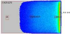
도 7은 실시 예의 효과를 설명하기 위한 것으로, 복합시트(24)의 굴절율 가변에 따른 광원(22)의 출광량을 시뮬레이션한 결과가 도시되어 있다. 도 7을 참조하면, 광원(22)과 도광판(16) 사이의 에어 갭이 존재할 때보다 에어 갭이 삭제될 때(복합시트를 구비할 때) 광원(22)의 출광량이 증가한 것을 알 수 있다. 그리고 복합시트(24)의 굴절율이 몰딩(38)의 굴절율인 1.53에 근접할수록 광원(22)의 출광량이 증가함을 알 수 있다.7 is a graph for explaining the effect of the embodiment, and shows the result of simulating the amount of light emitted by the
한편, 복합시트(24)는 광원(22)으로부터 입사된 광을 집광시켜 도광판(16)의 입사면에 공급한다. 이를 위해, 복합시트(24)는 제 1 및 제 3 층(44, 40) 사이에 제 2 층(42)을 구비하며, 제 2 층(42)은 다수의 프리즘 산(46)과 다수의 프리즘 산(46)들 사이에 충진된 공기를 포함한다. 다수의 프리즘 산(46)은 도광판(16)의 입사면 방향으로 돌출되며, 능선의 진행방향이 입사면의 길이방향과 나란하게 형성된다. 이러한 다수의 프리즘 산(46)과 다수의 프리즘 산(46) 사이에 충진된 공기는 광원(22)으로부터 입사된 광을 도광판(16)의 입사면에 수직한 방향으로 모아주는 역할을 한다.On the other hand, the
이와 같이, 다수의 프리즘 산(46)이 광을 집광하여 도광판(16)의 입사면에 공급하면, 도광판(16)의 입광부 주변에서 발생되는 휘선 불량을 방지할 수 있는데 그 이유는 다음과 같다.As described above, when a plurality of
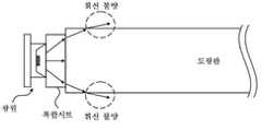
도 8a 및 도 8b는 비교 예에 따른 백라이트 유닛의 휘선 불량을 설명하기 위한 도면이다. 그리고 도 9a 및 9b는 실시 예에 따른 백라이트 유닛의 휘선 불량 방지 효과를 설명하기 위한 도면이다.FIGS. 8A and 8B are views for explaining defective bright lines of a backlight unit according to a comparative example. FIG. 9A and 9B are diagrams for explaining an effect of preventing the bright line defect of the backlight unit according to the embodiment.
만약, 도 8a에 도시된 바와 같이 복합시트가 다수의 프리즘 산을 미구비하면 복합시트 내에서 도광판의 상/하부면 방향으로 진행하는 광이 거의 굴절되지 않고 도광판에 입사된다. 이렇게 입사된 광은 도광판의 상/하부면에서 전반사되지 못하고 외부로 방출되는데, 이는 도광판의 상/하부면에 수직한 법선을 기준으로 할 때 해당 광의 입사각이 임계각보다 작기 때문이다. 따라서, 다수의 프리즘 산이 미구비된 비교 예는 도 8b에 도시된 바와 같이 도광판의 입광부 주변에서 휘선 불량이 발생된다.If a plurality of prism mountains are formed by the composite sheet as shown in FIG. 8A, the light traveling in the direction of the upper / lower surface of the light guide plate in the composite sheet is incident on the light guide plate without being substantially refracted. The incident light is totally reflected on the upper / lower surface of the light guide plate and is emitted to the outside because the incident angle of the light is smaller than the critical angle when the normal to the upper and lower surfaces of the light guide plate is taken as a reference. Thus, in the comparative example in which a plurality of prism mountains are not provided, a bright line defect occurs in the vicinity of the light-incoming portion of the light guide plate as shown in FIG. 8B.
반면, 도 9a에 도시된 바와 같이, 실시 예는 다수의 프리즘 산(46)이 복합시트(24) 내에서 도광판(16)의 상/하부면 방향으로 진행하는 광을 입사면에 수직한 방향으로 집광한다. 따라서, 도광판(16) 내에 입사된 광들은 입사각(도광판 상/하부면 기준)이 임계각보다 커지고, 도광판(16) 내부에서 전반사된다. 도 9b를 참조하면, 실시 예에 따라 다수의 프리즘 산(46)이 적용된 백라이트 유닛은 도광판(16)의 입광부 주변에서 휘선 불량이 크게 감소한 것을 알 수 있다.On the other hand, as shown in FIG. 9A, in the embodiment, a plurality of
한편, 복합시트(24)는 백라이트 유닛 구동시 도광판(16)의 열팽창으로 인한 도광판(16)과 광원(22)의 충돌을 방지하는 역할을 한다. 일반적으로 도광판(16)은 고온/고습 조건에서 0 ~ 2 mm 정도 팽창하므로 제 1 및 제 3 층(44, 40) 각각은 0.3 ~ 1 mm 의 두께를 갖는 것이 바람직하다. 또한, 복합시트(24)의 재질은 도광판(16)의 팽창시 충격을 흡수할 수 있도록 50 ~ 70 범위의 쇼어 경도를 갖는 것이 바람직하다.The
상술한 바와 같이, 실시 예에 따른 백라이트 유닛은 광원(22)과 도광판(16) 사이에 양면 각각이 광원(22)과 도광판(16)에 부착되는 복합시트(24)를 구비한다. 복합시트(24)는 양면이 점착력을 가지므로 도광판(16)과 광원(22)에 간단히 부착되어 조립공정이 유리해지며, 도광판(16)의 열팽창으로 인한 도광판(16)과 광원(22)의 충격방지 효과가 있다. 또한, 복합시트(24)는 광원(22)에서 발생된 열을 방출하는 방열 효과가 있다. 또한, 복합시트(24)의 재질은 몰딩(38)의 굴절율과 도광판(16)의 굴절율 사이의 굴절을 가짐으로써 백라이트 유닛의 광 효율을 높일 수 있다. 그리고 복합시트(24)는 다수의 프리즘 산(46)을 구비하여 도광판(16)의 입광부 주변에서 휘선 불량을 방지할 수 있다.As described above, the backlight unit according to the embodiment includes the
이상에서 설명한 본 발명은 상술한 실시 예 및 첨부된 도면에 한정되는 것이 아니고, 본 발명의 기술적 사상을 벗어나지 않는 범위 내에서 여러 가지 치환, 변형 및 변경이 가능하다는 것이 본 발명이 속하는 기술분야에서 통상의 지식을 가진 자에게 있어 명백할 것이다.It will be apparent to those skilled in the art that various modifications and variations can be made in the present invention without departing from the spirit or scope of the general inventive concept as defined by the appended claims and their equivalents. Will be clear to those who have knowledge of.
16: 도광판18: 다수의 광학시트
20: 반사판22: 광원
24: 복합시트16: light guide plate 18: multiple optical sheets
20: reflector 22: light source
24: Composite sheet
Claims (8)
Translated fromKorean상기 도광판의 적어도 한 측면에 배치되어 광을 방출하는 광원; 및
상기 광원과 상기 도광판 사이의 에어 갭(Air Gap) 없이 배치되어 양면 각각이 상기 광원 및 상기 도광판의 입사면에 부착되는 복합시트를 포함하고;
상기 복합시트는 상기 광원에 부착되는 제 1 층과, 상기 입사면에 부착되는 제 3 층, 및 다수의 프리즘 산을 포함하며 상기 제 1 층 및 상기 제 3 층 사이에 형성되는 제 2 층을 포함하고;
상기 다수의 프리즘 산은 상기 입사면 방향으로 돌출되며 능선의 진행방향이 상기 입사면의 길이방향과 나란하게 형성되며,
상기 복합시트는 몰딩의 굴절율과 상기 도광판의 굴절율 사이의 굴절율을 갖고, 50 ~ 70 범위의 쇼어 경도를 갖는 백라이트 유닛.A light guide plate that receives light through an incident surface;
A light source disposed on at least one side surface of the light guide plate to emit light; And
And a composite sheet which is disposed without an air gap between the light source and the light guide plate and is attached to an incident surface of the light source and the light guide plate,
The composite sheet includes a first layer attached to the light source, a third layer attached to the entrance surface, and a second layer comprising a plurality of prism mountains and formed between the first and third layers and;
The plurality of prism mountains protrude in the direction of the incident surface and the traveling direction of the ridgeline is formed to be parallel to the longitudinal direction of the incident surface,
Wherein the composite sheet has a refractive index between the refractive index of the molding and the refractive index of the light guide plate and has a Shore hardness in the range of 50 to 70. [
상기 광원은
인쇄회로기판에 설치되는 리드 프레임과;
상기 리드 프레임 내부에 배치된 발광 다이오드 칩; 및
상기 리드 프레임 내부에 충진되어 상기 발광 다이오드 칩을 보호하며 형광체가 혼합된 몰딩을 포함하는 다수의 발광 다이오드 패키지로 이루어진 것을 특징으로 하는 백라이트 유닛.The method according to claim 1,
The light source
A lead frame mounted on the printed circuit board;
A light emitting diode chip disposed inside the lead frame; And
And a plurality of light emitting diode packages packed in the lead frame to protect the light emitting diode chip and including a molding in which phosphors are mixed.
상기 복합시트의 재질은
1.40 ~ 1.55 의 굴절율을 갖는 것을 특징으로 하는 백라이트 유닛.The method according to claim 1,
The material of the composite sheet is
1. A backlight unit having a refractive index of 1.40 to 1.55.
상기 발광 다이오드 칩은
청색 광, 적색 광, 녹색 광, 백색 광 중에서 선택된 어느 하나의 광을 발생하는 것을 특징으로 하는 백라이트 유닛.3. The method of claim 2,
The light emitting diode chip
Wherein the light source generates any one of blue light, red light, green light, and white light.
상기 제 1 층 및 상기 제 3 층 각각은
0.3 ~ 1 mm 의 두께를 갖는 것을 특징으로 하는 백라이트 유닛.The method according to claim 1,
Each of the first and third layers
Wherein the backlight unit has a thickness of 0.3 to 1 mm.
상기 다수의 프리즘 산들 사이에는 공기가 충진되는 것을 특징으로 하는 백라이트 유닛.The method according to claim 1,
And air is filled between the plurality of prism mountains.
Priority Applications (1)
| Application Number | Priority Date | Filing Date | Title |
|---|---|---|---|
| KR1020110071291AKR101846409B1 (en) | 2011-07-19 | 2011-07-19 | Backlight unit |
Applications Claiming Priority (1)
| Application Number | Priority Date | Filing Date | Title |
|---|---|---|---|
| KR1020110071291AKR101846409B1 (en) | 2011-07-19 | 2011-07-19 | Backlight unit |
Publications (2)
| Publication Number | Publication Date |
|---|---|
| KR20130010580A KR20130010580A (en) | 2013-01-29 |
| KR101846409B1true KR101846409B1 (en) | 2018-04-09 |
Family
ID=47839760
Family Applications (1)
| Application Number | Title | Priority Date | Filing Date |
|---|---|---|---|
| KR1020110071291AActiveKR101846409B1 (en) | 2011-07-19 | 2011-07-19 | Backlight unit |
Country Status (1)
| Country | Link |
|---|---|
| KR (1) | KR101846409B1 (en) |
Families Citing this family (2)
| Publication number | Priority date | Publication date | Assignee | Title |
|---|---|---|---|---|
| KR102355587B1 (en)* | 2015-08-17 | 2022-01-26 | 엘지디스플레이 주식회사 | Back light Unit and Liquid Crystal Display Device having thereof |
| KR102598386B1 (en)* | 2016-11-29 | 2023-11-07 | 엘지디스플레이 주식회사 | Backlight unit and liquid crystal display device including same |
Citations (1)
| Publication number | Priority date | Publication date | Assignee | Title |
|---|---|---|---|---|
| KR100807296B1 (en)* | 2001-07-19 | 2008-02-28 | 엘지.필립스 엘시디 주식회사 | Backlight for Liquid Crystal Display |
- 2011
- 2011-07-19KRKR1020110071291Apatent/KR101846409B1/enactiveActive
Patent Citations (1)
| Publication number | Priority date | Publication date | Assignee | Title |
|---|---|---|---|---|
| KR100807296B1 (en)* | 2001-07-19 | 2008-02-28 | 엘지.필립스 엘시디 주식회사 | Backlight for Liquid Crystal Display |
Also Published As
| Publication number | Publication date |
|---|---|
| KR20130010580A (en) | 2013-01-29 |
Similar Documents
| Publication | Publication Date | Title |
|---|---|---|
| JP5717949B2 (en) | Optical member and display device | |
| CN206848653U (en) | A kind of backlight module and display device | |
| KR20240056476A (en) | Backlight Unit | |
| JP2006286638A (en) | Light emitting device having a plurality of light guide plates adjoining each other and overlapping | |
| CN103629627A (en) | Nanophosphor sheet and backlight device | |
| US20170317243A1 (en) | Light emitting diode package module and display device having the same | |
| KR101886127B1 (en) | Light emitting module and backlight unit having the same | |
| US9366801B2 (en) | Light emitting module, backlight unit including the light emitting module, and liquid crystal display including the backlight unit | |
| KR20090079568A (en) | Light source unit, manufacturing method thereof and display device having same | |
| US7478939B2 (en) | Backlight unit and liquid crystal display device comprising the same | |
| JP5944516B2 (en) | Edge light type surface light source device | |
| KR20140004881A (en) | Backlight unit | |
| KR101846409B1 (en) | Backlight unit | |
| KR101736926B1 (en) | Back light unit and liquid crystal display device having thereof | |
| KR20190009021A (en) | Display apparatus | |
| KR101918127B1 (en) | Backlight unit and Liquid crystal display device the same | |
| KR102611355B1 (en) | Quantum dot sheet and backlight unit and display device using the same | |
| KR102052742B1 (en) | Fluorescent substance film, backlight unit and display device comprising the same | |
| KR102355584B1 (en) | Backlight Unit and Display Device having the same | |
| KR20120047715A (en) | Light emitting diode, back light unit and liquid crystal display device having thereof | |
| KR101729776B1 (en) | Backlgiht unit and liquid crystal display device the same | |
| KR101915816B1 (en) | Display apparatus | |
| KR101892921B1 (en) | Light emitting module and backlight unit having the same | |
| CN105867017A (en) | Curved backlight unit | |
| KR20060058596A (en) | Backlight unit assembly |
Legal Events
| Date | Code | Title | Description |
|---|---|---|---|
| PA0109 | Patent application | Patent event code:PA01091R01D Comment text:Patent Application Patent event date:20110719 | |
| PG1501 | Laying open of application | ||
| A201 | Request for examination | ||
| PA0201 | Request for examination | Patent event code:PA02012R01D Patent event date:20160629 Comment text:Request for Examination of Application Patent event code:PA02011R01I Patent event date:20110719 Comment text:Patent Application | |
| E902 | Notification of reason for refusal | ||
| PE0902 | Notice of grounds for rejection | Comment text:Notification of reason for refusal Patent event date:20170519 Patent event code:PE09021S01D | |
| AMND | Amendment | ||
| E601 | Decision to refuse application | ||
| PE0601 | Decision on rejection of patent | Patent event date:20171103 Comment text:Decision to Refuse Application Patent event code:PE06012S01D Patent event date:20170519 Comment text:Notification of reason for refusal Patent event code:PE06011S01I | |
| AMND | Amendment | ||
| PX0901 | Re-examination | Patent event code:PX09011S01I Patent event date:20171103 Comment text:Decision to Refuse Application Patent event code:PX09012R01I Patent event date:20170718 Comment text:Amendment to Specification, etc. | |
| PX0701 | Decision of registration after re-examination | Patent event date:20180105 Comment text:Decision to Grant Registration Patent event code:PX07013S01D Patent event date:20171205 Comment text:Amendment to Specification, etc. Patent event code:PX07012R01I Patent event date:20171103 Comment text:Decision to Refuse Application Patent event code:PX07011S01I Patent event date:20170718 Comment text:Amendment to Specification, etc. Patent event code:PX07012R01I | |
| X701 | Decision to grant (after re-examination) | ||
| GRNT | Written decision to grant | ||
| PR0701 | Registration of establishment | Comment text:Registration of Establishment Patent event date:20180402 Patent event code:PR07011E01D | |
| PR1002 | Payment of registration fee | Payment date:20180403 End annual number:3 Start annual number:1 | |
| PG1601 | Publication of registration | ||
| PR1001 | Payment of annual fee | Payment date:20210315 Start annual number:4 End annual number:4 | |
| PR1001 | Payment of annual fee | Payment date:20220314 Start annual number:5 End annual number:5 | |
| PR1001 | Payment of annual fee | Payment date:20250318 Start annual number:8 End annual number:8 |