KR101846253B1 - Fluid treatment device - Google Patents
Fluid treatment deviceDownload PDFInfo
- Publication number
- KR101846253B1 KR101846253B1KR1020170140744AKR20170140744AKR101846253B1KR 101846253 B1KR101846253 B1KR 101846253B1KR 1020170140744 AKR1020170140744 AKR 1020170140744AKR 20170140744 AKR20170140744 AKR 20170140744AKR 101846253 B1KR101846253 B1KR 101846253B1
- Authority
- KR
- South Korea
- Prior art keywords
- fluid
- chamber case
- rotor
- chamber
- permanent magnet
- Prior art date
- Legal status (The legal status is an assumption and is not a legal conclusion. Google has not performed a legal analysis and makes no representation as to the accuracy of the status listed.)
- Expired - Fee Related
Links
Images


Classifications
- C—CHEMISTRY; METALLURGY
- C02—TREATMENT OF WATER, WASTE WATER, SEWAGE, OR SLUDGE
- C02F—TREATMENT OF WATER, WASTE WATER, SEWAGE, OR SLUDGE
- C02F1/00—Treatment of water, waste water, or sewage
- C02F1/48—Treatment of water, waste water, or sewage with magnetic or electric fields
- C02F1/481—Treatment of water, waste water, or sewage with magnetic or electric fields using permanent magnets
Landscapes
- Life Sciences & Earth Sciences (AREA)
- Hydrology & Water Resources (AREA)
- Engineering & Computer Science (AREA)
- Environmental & Geological Engineering (AREA)
- Water Supply & Treatment (AREA)
- Chemical & Material Sciences (AREA)
- Organic Chemistry (AREA)
- Water Treatment By Electricity Or Magnetism (AREA)
Abstract
Translated fromKoreanDescription
Translated fromKorean본 발명은 자기장 내에서 많은 캐비테이션을 반복적으로 발생시키는 유체처리장치에 관한 것으로서, 보다 상세하게는 유체 반응부가 유체 연결부를 통해 다단 원심펌프인 유체 유입부와 연결되며, 유체 유입부의 모터에 의해 구동되는 회전 샤프트에 유체 반응부의 로터가 끼워짐으로써, 하나의 모터 동력으로 다단 원심펌프의 임펠러와 유체 반응부의 로터를 구동할 수 있는 유체처리장치에 관한 것이다.The present invention relates to a fluid treatment apparatus that repeatedly generates a large number of cavitations in a magnetic field, and more particularly, to a fluid treatment apparatus in which a fluid reaction part is connected to a fluid inflow part through a fluid connection part and is driven by a motor of a fluid inflow part The present invention relates to a fluid treatment apparatus capable of driving a rotor of a fluid reaction unit and an impeller of a multi-stage centrifugal pump by a single motor power by fitting a rotor of a fluid reaction unit to a rotary shaft.
미국 특허 제7,762,715호(2010.7.27, 등록)는 다단의 스테이지 구조의 흐름 관로에 복수-제트-노즐, 나선 유로 가이드, 와류 발생장치를 혼용하여 하이드로다이나믹 캐비테이션을 발생시키고 있다.U.S. Patent No. 7,762,715 (Registered on July 27, 2010), hydro-dynamic cavitation is generated by using a multiple-jet-nozzle, a helical flow path guide, and a vortex generating device in a multi-stage flow structure.
미국 특허출원 제2013/016262호(2013.6.27. 출원)는 기계적인 하이드로캐비테이션 장치와 전자석 장치를 사용하여 하수처리공정에서 유체 중의 미세입자를 응집 시키고 미생물을 살균하여 처리효율을 높이고 있다.U.S. Patent Application No. 2013/016262 (filed on June 27, 2013) utilizes a mechanical hydro-cavitation device and an electromagnet device to coagulate fine particles in a fluid in a sewage treatment process and sterilize microorganisms, thereby improving treatment efficiency.
미국 특허출원 제2006/0126428호(2006.6.15. 출원)는 챔버 내에서 회전하는 디스크 외주면에 원주형 홈을 다수 배치한 후 디스크를 고속으로 회전시킨 상태에서 챔버와 디스크 외주면 사이의 공간에 유체를 흐르게 하면 디스크 외주면 상의 홈과 챔버 내면이 상응하여 캐비테이션이 발생되어, 미세 기포의 생성, 유체의 혼합, 유체의 산화 작용으로 BOD 및 COD의 저감, 에멀젼 유체의 분리 등에 적용하고 있다.U.S. Patent Application No. 2006/0126428 (filed on Jun. 15, 2006) discloses a method for manufacturing a disk-shaped recording medium having a plurality of circumferential grooves arranged on a circumferential surface of a rotating disk in a chamber, Cavitation is generated corresponding to grooves on the outer peripheral surface of the disk and the inner surface of the chamber, so that BOD and COD are reduced due to generation of fine bubbles, mixing of fluids, oxidation of fluids, and separation of emulsion fluids.
중국 특허 제CN103896387호(2014.2.7, 등록)은 벤추리 형상의 장치로 캐비테이션을 발생시켜, 산화 하이드록실기(.OH)와 수소 환원기(.H)를 형성시키는데, 압력이 재 상승하는 벤추리 구조 후단 부에 영구자석 또는 전자석을 배치하여 기포 파공을 강화시키고, 기포 파공 시간을 단축 시키고 있다.China Patent No. CN103896387 (registered on February 7, 2014) is a venturi-shaped device that generates cavitation and forms an oxidative hydroxyl group (.OH) and a hydrogen reducing group (.H) Permanent magnets or electromagnets are disposed at the rear end to strengthen the bubble pores and shorten the bubble pore time.
중국 특허 제CN103214068호(2014.3.5. 등록)는 원형관 내부에 이중 구조 형상의 벤추리 형상의 구조물을 배치하여 원형관 내부와 벤추리 구조물 간의 폭 차이에 따른 유속의 변화와 이에 상응하는 압력 차이로 캐비테이션을 발생시킨다. 이때, 벤추리 형상의 좁은 부분에 영구자석을 배치하여 캐비테이션을 강화시킨다.China Patent No. CN103214068 (registered on March 5, 2014) places a venturi-like structure with a dual structure inside a circular tube, so that the difference in velocity between the inside of the circular tube and the venturi structure and the corresponding pressure difference cause cavitation . At this time, a permanent magnet is disposed in a narrow part of the venturi shape to strengthen the cavitation.
유럽 특허 제EP0826416호(1996.10.24) 및 미국 특허 제US6016798호 (2000.6.26)는 챔버 내에서 회전하는 디스크 외주 면에 원주형 홈을 다수 배치한 후 디스크를 고속으로 회전시킨 상태에서 챔버와 디스크 외주면 사이의 공간에 유체를 흐르게 하면 디스크 외주면 상의 홈과 챔버 내면이 상응하여 캐비테이션이 발생되고, 유체의 온도를 높이게 한다.European Patent No. EP0826416 (Oct. 24, 1996) and US Pat. No. 6,016,798 (Jun. 26, 2000) disclose a method of disposing a plurality of circumferential grooves on the outer circumferential surface of a rotating disk in a chamber, When the fluid is caused to flow through the space between the outer circumferential surfaces, cavitation is generated corresponding to the groove on the outer circumferential surface of the disk and the inner surface of the chamber, thereby raising the temperature of the fluid.
한국 특허출원 제10-2013-0125696호(2013.10.22) 및 한국 특허출원 제10-2013-012599호(2013.10.22)는 캐비테이션 발생장치 및 유체 자화장치를 순차로 조합하여 유체 중의 미생물을 살균하고, 미세입자를 분리하고 있다.Korean Patent Application No. 10-2013-0125696 (Oct. 22, 2013) and Korean Patent Application No. 10-2013-012599 (Oct. 22, 2013) combine a cavitation generator and a fluid magnetization device in sequence to sterilize microorganisms in the fluid , And the fine particles are separated.
일반적으로, 하이드로다이나믹 캐비테이션은 개구면(orifice) 또는 어떤 다른 기계적인 수축으로 유체의 흐름 압력이 액체의 증발 압력 이하로 떨어질 때 발생한다. 그리고, 개구면을 통해 흐르는 물에서, 흐름의 단면-부분을 감소시키면 압력 수두 차이 만큼 유속이 증가하고, 흐름이 다시-확장되는 동안 유체 흐름은 개구부의 하저부에서 분리되어 와류를 생성한다.Generally, hydrodynamic cavitation occurs when the flow pressure of the fluid drops below the liquid evaporation pressure due to an orifice or some other mechanical contraction. And, in the water flowing through the opening, decreasing the cross-section of the flow increases the flow velocity by the pressure head difference, and while the flow re-expands, the fluid flow is split at the bottom of the opening to create a vortex.
특정 유속에서는 다시-확장되는 동안 유체 흐름 압력이 물의 증발 압력 이하로 떨어져 미세 기포 발생 원인이 된다. 만일 수중에 용존 가스가 존재 한다면, 낮은 압력에서 탈 가스화가 발생되므로, 증발 압력 이상의 압력에서 특히 캐비테이션이 관측된다.At certain flow rates, the fluid flow pressure drops below the evaporation pressure of water during re-expansion, causing microbubbles. If dissolved gas is present in the water, degassing occurs at low pressures, so cavitation is observed especially at pressures above the evaporation pressure.
캐비테이션에 의한 미세 기포의 급격한 융폭(impulsion)은 기포/물 경계 면에 고온을 발생시켜 액체 중의 유기물을 열 변화시키고, 물분자의 열변화에 의하여 생성된 -OH기 또한 유기물을 산화시켜 제거한다. 캐비테이션 중에 발생하는 극심한 조건은 물을 산화기(oxidation radical; .OH) 및 환원기(reducing radical; .H) 2 종으로 변화시킨다. 다른 최신 산화공정(Advanced Oxidation Processes)과 같이, 캐비테이션에 의해 유기물을 제거하는 기본 메커니즘은 하이드록실기(hydroxyl radical) 반응 (유기물 + OH- -> CO2 + H20)을 통해서 이다.The rapid impulse of micro-bubbles by cavitation generates high temperatures at the bubble / water interface to thermally change the organic substances in the liquid, and the -OH groups generated by the heat changes of the water molecules are also removed by oxidizing the organic substances. The extreme conditions that occur during cavitation change water into two kinds of oxidation radicals (.OH) and reducing radicals (.H). Like other Advanced Oxidation Processes, the basic mechanism for removing organic matter by cavitation is through a hydroxyl radical reaction (organics + OH- -> CO2 + H2 O).
이러한 캐비테이션을 생성하는 데는 다음과 같은 다양한 메커니즘이 있다. There are various mechanisms for generating such cavitation as follows.
1) 유속이 와류(Eddy) 또는 회전류(Vortices)를 생성할 만큼 한계 범주를 벗어나도록 증가1) Increase to exceed the marginal category enough to create eddy or rotating current (Vortices)
2) 초음파 분해(sonication)를 통해 경계면(Boundary)의 급격한 진동 발생2) Sudden vibration of the boundary due to ultrasonic sonication
3) 워터 해머(Water Hammer)로 인해 액체 층(liquid column)의 분리 또는 이격3) Water hammer separates or separates the liquid column
4) 정압(Static pressure)의 전반적인 감소4) Overall reduction of static pressure
아니루드하 판디트(Aniruddha B. Pandit) 등이 Current Science(Vol. 91 No.1, 2006.07.10)에 발표한 "Cavitation: A technology on the horizon"에 의하면 "하이드로다이나믹 캐비테이션은 지금까지 사용되어온 총 에너지 소비량의 5~10% 이하의 에너지로 미생물 셀을 파공하는데 효과적으로 사용될 수 있다. 캐비테이션 현상의 강도는 셀을 파공하는데 적합하도록 제어할 수 있으며, 셀의 벽 내부에 존재하는 내부 효소를 분리하는데도 선택적으로 이용할 수 있다." 라고 발표하였다.According to "Cavitation: A technology on the horizon" published in Current Science (Vol. 91 No.1, 2006.07.10) by Aniruddha B. Pandit et al., "Hydrodynamic cavitation The strength of the cavitation phenomenon can be controlled so as to be suitable for pitting the cell, and it is also possible to separate internal enzymes existing inside the walls of the cell It is optionally available. " .
한편, 자기장은 이온 주변에 위치하는 유체에 영향을 주어 수화셀의 비대칭을 만드는 것으로 알려진다. 또한, 자기장은 뒤따르는 다른 증폭 결합으로 어떤 이온 간의 결합을 약화시킨다. 이러한 변화는 이온의 결합 또는 결정의 핵을 형성하게 한다. 결과적으로 자기의 반대 흐름은 이온 운동의 방향을 변경하였으며, 이온 쌍 형성을 매우 손쉽게 하고 더 복잡하게 모아지게 하여 가까이 있는 입자를 응집 하는데 크게 기여한다. 용액 중에 단단한 표면이 있으면 결정 형성에 소요되는 에너지가 용액 중에서 핵이 형성되는 데 소요되는 것보다 상당히 적기 때문에 응집이 상당히 빨리 진행된다. 이러한 자기장 특성을 이용하여 배관 내부의 스케일 형성 억제 또는 제거, 수처리 공정의 처리 효율을 향상시키는 다양한 장치가 상용화되어 있다.On the other hand, it is known that the magnetic field affects the fluid located around the ions, thereby making the hydration cell asymmetric. In addition, the magnetic field weakens the bond between certain ions with subsequent amplification bonds. These changes lead to the formation of nuclei of the bonds or crystals of ions. As a result, the counter-current of the magnetic field changes the direction of the ion motion, making ion pair formation very easy and more complicated to contribute to the aggregation of nearby particles. If there is a hard surface in the solution, aggregation proceeds considerably faster because the energy required for crystal formation is considerably less than that required for nucleation in solution. Various devices for improving or suppressing the formation of scales inside the piping by using such magnetic field characteristics and improving the treatment efficiency of the water treatment process have been commercialized.
안드류 골드스워쓰(Andrew Goldsworthy)가 2007년 발표한 "The Biological Effect of Weak Electromagnetic Field"에 의하면, "전자기장이 미생물 셀에서 칼슘을 분리해내어 칼슘 결핍으로 미생물 셀의 막을 약하게 만든다. 칼슘 이온은 미생물 셀 멤브레인의 표면에 결합하여 미생물의 안정성을 유지하는데 중요하다. 칼슘 이온은 미생물 생성에 필수적 부분인 포스폴리피드 (phospholipid) 분자가 함께 붙어 있도록 돕는다. 칼슘 이온이 없으면 셀 멤브레인이 약해져서 셀의 이동에 의한 스트레스와 충격에 더 쉽게 찢어진다" 라고 발표하였다.According to "The Biological Effect of Weak Electromagnetic Field" published by Andrew Goldsworthy in 2007, "Electromagnetic field separates calcium from microbial cells and weakens the membrane of microbial cells with calcium deficiency. It is important to maintain the stability of the microorganism by binding to the surface of the microbial cell membrane. Calcium ions help to attach phospholipid molecules, which are essential for microbial production. Without calcium ions, the cell membrane becomes weak, And it is more easily torn by the stress and shock of ".
수스리크(Suslick, 1989)외 여러 연구자들은 캐비테이션 현상은 유체 중에 형성된 미세 기포가 한계 공명 크기에 도달한 후 증발 압력에 도달하면 격렬히 융폭하여 국소적으로 고온(5000°C) 및 고압(1000 atm)을 발생하는 것으로 발표하였다. 캐비테이션에 의해 형성되는 주요 현상은 다음과 같다.Suslick et al. (1989) and others have noted that cavitation phenomena occur when the microbubbles formed in a fluid reach a critical resonance amplitude and then vigorously vibrate when reaching the vapor pressure, locally reaching high temperatures (5000 ° C) and high pressure (1000 atm) As a result. The main phenomena formed by cavitation are as follows.
- 유체의 점도, 표면장력 및 증발 압력 등이 감소- reduced fluid viscosity, surface tension and evaporation pressure
- 유체 온도 상승- fluid temperature rise
- 용존 가스의 실체화- Realization of dissolved gas
- 집약된 에너지가 유체에 신속하게 전달됨.- Intensive energy is transferred quickly to the fluid.
- 격렬한 와류는 에너지 이전을 가속시킴.- Vigorous vortex accelerates energy transfer.
미세 기포의 급격한 폭발로 발생한 고온은 액체 중의 유기물을 열변화시키고 물분자의 열변화에 의하여 생성된 OH-기 또한 유기물을 산화시켜 제거한다. 캐비테이션 중에 발생하는 극심한 조건은 물을 부분적으로 산화기(oxidation radical; OH-) 및 환원기(reducing radical; H+) 2 종으로 변화시킨다. 또한, 캐비테이션에 의해 발생한 국소적인 고압의 융폭은 주변의 미생물의 셀 막을 파공하여 미생물 셀 내부의 효소, 리피드스 및 생체 구성물을 셀 밖으로 흩어버리므로 미생물을 사멸하는 효과를 가져온다.The high temperature generated by the sudden explosion of minute bubbles causes the organic substances in the liquid to be thermally changed and the OH- groups generated by the heat change of the water molecules to oxidize and remove the organic substances. The extreme conditions that occur during cavitation change water partially into two oxidation radicals (OH- ) and reducing radicals (H+ ). In addition, the local high pressure blowing caused by the cavitation pierces the cell membrane of the surrounding microorganisms and disperses the enzymes, lipids, and bio-constituents inside the microbial cells out of the cell, thereby killing the microorganisms.
자기장은 이온 주변에 위치하는 유체 분자에 영향을 주므로 수화셀의 비대칭을 만드는 것으로 알려진다. 또한, 자기장은 뒤따르는 다른 증폭 결합으로 어떤 이온 간의 결합을 약화시킨다. 이러한 변화는 이온의 결합 또는 결정의 핵을 형성하게 한다. 결과적으로 자기의 반대 흐름은 이온 운동의 방향을 변경하였으며, 이온 쌍 형성을 매우 손쉽게 하고 더 복잡하게 모아지게 하여 가까이 있는 입자를 응집하는데 크게 기여한다. 용액 중에 단단한 표면이 있으면 결정 형성에 소요되는 에너지가 용액 중에서 핵이 형성되는 데 소요되는 것보다 상당히 적기 때문에 응집이 상당히 빨리 진행된다.The magnetic field is known to make the asymmetry of the hydration cell because it affects fluid molecules located around the ion. In addition, the magnetic field weakens the bond between certain ions with subsequent amplification bonds. These changes lead to the formation of nuclei of the bonds or crystals of ions. As a result, the counter-current of the magnetic field changes the direction of the ion motion, making ion pair formation very easy and more complicated to contribute to the aggregation of nearby particles. If there is a hard surface in the solution, aggregation proceeds considerably faster because the energy required for crystal formation is considerably less than that required for nucleation in solution.
상용화된 유체 자화반응기는 구성에 따라 매우 다양하다. 대부분의 산업용 유체 자화반응기에서는, 고정된 자기장을 통해 분산된 유체를 흐르게 한다. 일부 경우, 자기장이 변형되거나 맥동되게 하고 주요 흐름에서 난류를 이루게 한다. 대부분의 유체 자화반응기 실험에서, 작동 채널의 유속(v), 자기장이 적용되는 직각 방향의 자기 밀도(B), 작동 채널 중의 유체 체류시간(τ)으로 정하면, Bτv 값은 유체 자화반응 장치의 효율에 매우 중요한 항목임을 보여준다.Commercial fluidized magnetization reactors vary widely depending on the configuration. In most industrial fluid magnetization reactors, a dispersed fluid flows through a fixed magnetic field. In some cases, the magnetic field is deformed or pulsating and turbulent in the main flow. In most fluid magnetization reactor experiments, the value of Bτv, determined by the flow velocity v of the operating channel, the magnetic density B in the perpendicular direction to which the magnetic field is applied, and the fluid residence time in the operating channel, This is a very important item.
정지된 자기장 내에서 도선을 이동하거나, 정지된 도선을 감싸면서 자기장이 이동하면 도선 내의 전자의 흐름에 기인한 기전력(Electromotive Force)이 발생한다. 기전력의 크기 및 방향은 자기장(B)의 방향, 도선 내부의 입자의 진행 속도 및 입자의 전하량에 따라 결정되며 파라데이법칙에 따라 다음과 같이 계량된다.Electromotive force due to the flow of electrons in the conductor occurs when the magnetic field moves while moving the conductor in a stationary magnetic field. The magnitude and direction of the electromotive force are determined by the direction of the magnetic field (B), the velocity of the particles inside the conductor, and the amount of charge of the particles.
(수학식 1)(1)

* 주: FL= 기전력, q= 입자 전하량, V= 입자 이동속도, B= 자기장 강도, α= 이온 흐름에 대한 자기장 방향의 각도* Note: FL = electromotive force, q = particle charge, V = particle transport velocity, B = magnetic field strength,
자기장은 미생물 셀의 외피 막을 구성하고 있는 칼슘이온을 셀에서 분리해내어 미생물 셀의 막을 약하게 만든다. 칼슘 이온은 미생물 셀 멤브레인의 표면에 결합하여 미생물의 안정성을 유지하는데 중요하다. 칼슘 이온은 미생물 생성에 필수적 부분인 포스폴리피드(phospholipid) 분자가 함께 붙어 있도록 돕는다. 칼슘 이온이 없으면 셀 멤브레인이 약해져서 셀의 이동에 의한 스트레스와 충격에 더 쉽게 찢어진다.The magnetic field separates the calcium ions forming the outer membrane of the microbial cell from the cell and weakens the membrane of the microbial cell. Calcium ions are important to maintain microbial stability by binding to the surface of the microbial cell membrane. Calcium ions help to attach phospholipid molecules, which are essential for microbial production. Without calcium ions, the cell membrane is weakened and is more easily torn by the stress and shock of cell migration.
미생물의 신진대사 과정의 에너지 생성 메커니즘의 하나인 산화-환원 과정 중 원자 또는 분자에서 전자의 제거와 전자의 흡수 과정은 미생물의 생존과 증식에 매우 중요하다. 유체 중에 포함된 미생물이 강력한 자기장에 노출되면 신진대사에 소요되는 전자가 박리되어 전위가 낮은 지점으로 흘러버리므로 미생물이 사멸되는 효과를 가져온다.The removal of electrons from atoms or molecules and the absorption of electrons during the oxidation-reduction process, which is one of the energy generation mechanisms of microbial metabolism, are very important for the survival and proliferation of microorganisms. When a microorganism contained in a fluid is exposed to a strong magnetic field, the electrons required for metabolism are peeled off and flow to a site having a low potential, resulting in the microorganisms being killed.
따라서, 본 발명의 목적은 유체 반응부가 유체 연결부를 통해 다단 원심펌프인 유체 유입부와 연결되며, 유체 유입부의 모터에 의해 구동되는 회전축에 유체 반응부의 로터가 끼워짐으로써, 하나의 모터 동력으로 다단 원심펌프의 임펠러와 유체 반응부의 로터를 구동할 수 있어, 효율적이고, 유체가 다단 원심펌프인 유체 유입부에 의해 고압으로 가압되고, 고압으로 가압된 유체가 유체 반응부를 통과하는 과정에서 캐비테이션과 유체 자화가 동시에 효율적으로 발생하는 유체처리장치를 제공하는 것이다.Accordingly, it is an object of the present invention to provide a multi-stage centrifugal pump which is connected to a fluid inlet through a fluid connection part through a fluid connection part, and a rotor of the fluid reaction part is fitted to a rotary shaft driven by a motor of the fluid inlet part, It is possible to drive the impeller of the centrifugal pump and the rotor of the fluid reaction part efficiently and to pressurize the high pressure fluid by the fluid inflow part which is a multi-stage centrifugal pump, And to provide a fluid treatment apparatus in which magnetization is efficiently generated at the same time.
또한, 본 발명의 다른 목적은 상기와 같은 본 발명에 따른 유체처리장치를 무화염 가온 시스템, 미생물 살균 이외의 용도(유체 중의 미세입자 분리, 산업용 냉각 계통수 처리, 폐수의 BOD 및 COD 저감, 콘크리트 산업용수 처리, 농업용수 처리, 양어용수 처리, 남조류에서 바이오디젤용 원유 추출, 호소 수질정화 등)에 이용될 수 있도록 적용하는 것이다.Another object of the present invention is to provide a fluid treatment apparatus according to the present invention as described above as a non-flame heating system, for applications other than microbial sterilization (microparticle separation in fluid, industrial cooling water treatment, reduction of BOD and COD of wastewater, Such as water treatment, agricultural water treatment, aqueous fish water treatment, crude oil extraction for biodiesel from cyanobacteria, purification of lake water quality, etc.).
상기와 같은 목적을 달성하기 위한 본 발명에 따른 유체처리장치는 유체 반응부가 유체 연결부를 통해 다단 원심펌프인 유체 유입부와 연결되며, 유체 유입부의 모터에 의해 구동되는 회전 샤프트에 다단 원심펌프인 유체 유입부의 임펠러와, 유체 반응부의 로터가 각각 끼워지고, 회전 샤프트에 의해 유체 반응부의 로터가 회전하게 되며, 유체 반응부가 제 1 챔버 케이스와, 로터와, 제 2 챔버 케이스를 포함하고, 제 1 챔버 케이스의 제 1 영구자석과 제 2 챔버 케이스의 제 2 영구자석이 서로 마주보게 배치되며, 제 1 영구자석과 제 2 영구자석 사이에 로터가 배치되고, 제 1 챔버 케이스와 제 2 챔버 케이스에 다수개의 작은 홈이 각각 형성되고, 로터의 양 측면에 방사상으로 다수개의 곡선홈이 형성됨으로써, 유체가 유체 유입부를 통과하는 과정에서 고압으로 가압되고, 고압으로 가압된 유체가 유체 반응부를 통과하는 과정에서, 제 1 영구자석과 제 2 영구자석에 의해 자화되고, 제 1 챔버 케이스와 제 2 챔버 케이스에 형성된 다수개의 작은 홈과 로터의 곡선홈에 의해 캐비테이션이 발생하게 되는 것을 특징으로 한다.According to an aspect of the present invention, there is provided a fluid treatment apparatus including a fluid reaction unit connected to a fluid inlet, which is a multi-stage centrifugal pump, through a fluid connection unit, The impeller of the inlet portion and the rotor of the fluid reaction portion are respectively fitted and the rotor of the fluid reaction portion is rotated by the rotary shaft, and the fluid reaction portion includes the first chamber case, the rotor and the second chamber case, The first permanent magnet of the case and the second permanent magnet of the second chamber case are disposed to face each other, the rotor is disposed between the first permanent magnet and the second permanent magnet, and the first chamber case and the second chamber case And a plurality of curved grooves are radially formed on both side surfaces of the rotor, so that when the fluid passes through the fluid inflow portion, And a plurality of small grooves formed in the first chamber case and the second chamber case and a plurality of small grooves formed in the second chamber case and magnetized by the first permanent magnet and the second permanent magnet in the process of passing the fluid pressurized by the high pressure through the fluid reaction part, And the cavitation is generated by the curved groove.
상기 유체 연결부는 원통 관 형상으로서 내부가 벤추리관 형상으로 이루어지며, 중앙 목부의 내경은 유효 단면적이 흡입구의 단면적의 90%에 상응하도록 정해지고, 좌측 플랜지가 유체 배출구에 볼트에 의해 결합되고, 우측 플랜지가 제 1 챔버 케이스에 볼트에 의해 결합되는 것을 특징으로 한다.Wherein the fluid connection portion is formed in a cylindrical tube shape and the inside is formed in a venturi tube shape and the inner diameter of the center neck portion is determined such that the effective cross sectional area corresponds to 90% of the cross sectional area of the intake port, the left flange is bolted to the fluid discharge port, And the flange is coupled to the first chamber case by bolts.
상기 유체 반응부는 제 1 챔버 케이스의 둘레에 형성된 제 1 플랜지와 제 2 챔버 케이스의 둘레에 형성된 제 2 플랜지가 볼트에 의해 결합되고, 제 1 챔버 케이스의 외측면에 링 형태의 제 1 장착홈이 형성되고, 제 1 장착홈에 제 1 영구자석이 장착되며, 제 2 챔버 케이스의 외측면에 링 형태의 제 2 장착홈이 형성되고, 제 2 장착홈에 제 2 영구자석이 장착되며, 링 형태의 제 1 영구자석과 링 형태의 제 2 영구자석이 서로 마주보게 배치되고, 제 1 챔버 케이스의 내측면과 제 2 챔버 케이스의 내측면 사이에 로터가 배치되며, 제 1 챔버 케이스의 내측면과 로터 사이 그리고 제 2 챔버 케이스의 내측면과 로터 사이에 유체통과간극이 각각 형성되고, 회전 샤프트가 제 1 챔버 케이스의 중공부와 로터와 제 2 챔버 케이스의 중공부에 끼워져, 회전 샤프트에 의해 로터가 제 1 챔버 케이스와 제 2 챔버 케이스에 대해 상대적으로 회전하게 되며, 로터의 양 측면에 방사상으로 형성된 다수개의 곡선홈이 형성되고, 로터와 마주보는 제 1 및 제 2 챔버 케이스의 내측면에 다수개의 작은 홈이 각각 형성되며, 다수개의 작은 홈이 방사상으로 커브 라인을 형성하고, 다수개의 커브 라인이 제 1 및 제 2 챔버 케이스의 내측면에 각각 형성되는 것을 특징으로 한다.The fluid reacting portion includes a first flange formed around the first chamber case and a second flange formed around the second chamber case by bolts, and a ring-shaped first mounting groove is formed on the outer surface of the first chamber case A second mounting groove is formed on the outer surface of the second chamber case, a second permanent magnet is mounted on the second mounting groove, and a ring-shaped And a rotor is disposed between the inner surface of the first chamber case and the inner surface of the second chamber case, and the inner surface of the first chamber case and the inner surface of the first chamber case A fluid passage gap is formed between the rotor and the inner side surface of the second chamber case, and the rotating shaft is inserted into the hollow portion of the first chamber case and the hollow portion of the rotor and the second chamber case, Wherein a plurality of curved grooves formed on both sides of the rotor are formed and a plurality of curved grooves are formed on inner surfaces of the first and second chamber cases facing the rotor, A plurality of small grooves are formed radially to form a curved line, and a plurality of curved lines are formed on inner sides of the first and second chamber cases, respectively.
상기 제 1 및 제 2 챔버 케이스의 커브라인은 인벌류트 곡선(involute curve), 사이클로이드 곡선(cycloid curve), 스파이럴 곡선(spiral curve), 또는 헬릭스 곡선(helix curve) 중 어느 한 곡선인 것을 특징으로 한다.The curve lines of the first and second chamber cases are characterized by being any one of an involute curve, a cycloid curve, a spiral curve, and a helix curve .
상기 로터의 곡선홈은 인벌류트 곡선(involute curve), 사이클로이드 곡선(cycloid curve), 스파이럴 곡선(spiral curve), 또는 헬릭스 곡선(helix curve) 중 어느 한 곡선인 것을 특징으로 한다.The curved groove of the rotor is characterized by being either an involute curve, a cycloid curve, a spiral curve, or a helix curve.
상기 작은 홈의 깊이는 로터의 곡선홈의 깊이의 1~1.5배이고, 간극은 곡선홈의 깊이의 0.1~0.2배인 것을 특징으로 한다.The depth of the small groove is 1 to 1.5 times the depth of the curved groove of the rotor and the gap is 0.1 to 0.2 times the depth of the curved groove.
이것에 의해, 본 발명에 따른 유체처리장치는 하나의 모터 동력으로 다단 원심펌프의 임펠러와 유체 반응부의 로터를 구동할 수 있어, 효율적이고, 캐비테이션과 유체 자화가 동시에 효율적으로 발생하며, 무화염 가온 시스템, 미생물 살균 이외의 용도(유체 중의 미세입자 분리, 산업용 냉각 계통수 처리, 폐수의 BOD 및 COD 저감, 콘크리트 산업용수 처리, 농업용수 처리, 양어용수 처리, 남조류에서 바이오디젤용 원유 추출, 호소 수질정화 등)에 이용될 수 있는 효과가 있다.Thus, the fluid treatment apparatus according to the present invention can efficiently drive the impeller of the multi-stage centrifugal pump and the rotor of the fluid reaction part by one motor power, efficiently generate cavitation and fluidization simultaneously, System, except for microbial disinfection (separation of fine particles in fluid, treatment of industrial cooling water, reduction of BOD and COD of wastewater, treatment of concrete industrial water, treatment of agricultural water, treatment of marine water, extraction of crude oil for biodiesel, And the like).
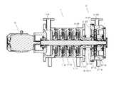
도 1은 본 발명에 따른 유체처리장치를 도시한 사시도이다.
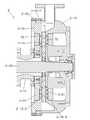
도 2는 본 발명에 따른 유체처리장치를 도시한 단면도이다.
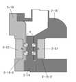
도 3은 도 2의 유체 반응부를 확대 도시한 상세도이다.
도 4 및 도 5는 유체 반응부의 내부에서 유체의 흐름을 도시한 개략도로, 도 4는 챔버 케이스의 작은 홈과 로터의 곡선홈이 불일치된 상태이고, 도 5는 챔버 케이스의 작은 홈과 로터의 곡선홈이 일치된 상태이다.
도 6은 유체 반응부의 제 1 챔버 케이스를 도시한 사시도이다.
도 7은 유체 반응부의 제 2 챔버 케이스를 도시한 사시도이다.
도 8은 로터의 정면을 도시한 사시도이다.
도 9는 로터의 배면을 도시한 사시도이다.1 is a perspective view showing a fluid treatment apparatus according to the present invention.
2 is a cross-sectional view showing a fluid treatment apparatus according to the present invention.
FIG. 3 is an enlarged view showing the fluid reaction unit of FIG. 2. FIG.
4 and 5 are schematic views showing the flow of the fluid inside the fluid reaction part, Fig. 4 is a state in which the small grooves of the chamber case and the curved grooves of the rotor are inconsistent, Fig. 5 is a cross- The curved grooves are in agreement.
6 is a perspective view showing the first chamber case of the fluid reaction part.
7 is a perspective view showing a second chamber case of the fluid reaction part.
8 is a perspective view showing the front surface of the rotor.
9 is a perspective view showing a rear surface of the rotor.
이하, 본 발명의 바람직한 실시예를 도면을 참조하여 상세하게 설명하기로 한다.Hereinafter, preferred embodiments of the present invention will be described in detail with reference to the drawings.
도 1 내지 도 3을 참조하면, 본 발명에 따른 유체처리장치는 유체 반응부(2)가 유체 연결부(2-12)를 통해 다단 원심펌프인 유체 유입부(1)와 연결되며, 유체 유입부(1)의 모터(3)에 의해 구동되는 회전 샤프트(2-23)에 다단 원심펌프인 유체 유입부(1)의 임펠러(1-9)와, 유체 반응부(2)의 로터(2-14)가 각각 끼워지고, 회전 샤프트(2-23)에 의해 유체 반응부(2)의 로터(2-14)가 회전하게 되며, 유체 반응부(2)가 제 1 챔버 케이스(2-13)와, 로터(2-14)와, 제 2 챔버 케이스(2-15)를 포함하고, 제 1 챔버 케이스(2-13)의 내측면과 로터(2-14) 사이 그리고 제 2 챔버 케이스(2-15)의 내측면과 로터(2-14) 사이에 유체통과간극(T3)이 각각 형성되고, 제 1 챔버 케이스(2-13)의 제 1 영구자석(2-22)과 제 2 챔버 케이스(2-15)의 제 2 영구자석(2-21)이 서로 마주보게 배치되며, 제 1 영구자석(2-22)과 제 2 영구자석(2-21) 사이에 로터(2-14)가 배치되고, 제 1 챔버 케이스(2-13)와 제 2 챔버 케이스(2-15)에 다수개의 작은 홈(T2)이 각각 형성되고, 로터(2-14)의 양 측면에 방사상으로 다수개의 곡선홈(T1)이 형성됨으로써, 유체가 유체 유입부(1)를 통과하는 과정에서 고압으로 가압되고, 고압으로 가압된 유체가 유체 반응부(2)를 통과하는 과정에서, 제 1 영구자석(2-22)과 제 2 영구자석(2-21)에 의해 자화되고, 제 1 챔버 케이스(2-13)와 제 2 챔버 케이스(2-15)에 형성된 다수개의 작은 홈(T2)과 로터(2-14)의 곡선홈(T1)에 의해 캐비테이션이 발생하게 된다.1 to 3, a fluid treatment apparatus according to the present invention is characterized in that the fluid reaction section 2 is connected to a fluid inlet section 1, which is a multi-stage centrifugal pump, through a fluid connection section 2-12, The impeller 1-9 of the fluid inflow section 1 which is a multi-stage centrifugal pump and the impeller 1-9 of the rotor 2 of the fluid reaction section 2 are connected to the rotary shaft 2-23 driven by the motor 3 of the fluid reaction section 1, The rotor 2-14 of the fluid reaction part 2 is rotated by the rotary shaft 2-23 and the fluid reaction part 2 is rotated by the first chamber case 2-13, A rotor 2-14 and a second chamber case 2-15 and is arranged between the inner side of the first chamber case 2-13 and the rotor 2-14 and between the second chamber case 2 And a fluid passage gap T3 is formed between the inner surface of the first chamber case 2-13 and the rotor 2-14 and the first permanent magnet 2-22 of the first chamber case 2-13, The second permanent magnets 2-21 of the first permanent magnets 2-15 are disposed opposite to each other, and the first permanent magnets 2-22 and the second permanent magnets A rotor 2-14 is disposed between the stones 2-21 and a plurality of small grooves T2 are formed in the first chamber case 2-13 and the second chamber case 2-15, A plurality of curved grooves T1 are radially formed on both sides of the rotor 2-14 so that the fluid is pressurized at a high pressure in the course of passing through the fluid inflow portion 1, The first chamber case 2-13 and the second chamber case 2-22 are magnetized by the first permanent magnet 2-22 and the second permanent magnet 2-21 in the process of passing through the first chamber case 2-2 and the second chamber case 2-23, Cavitation occurs due to the plurality of small grooves T2 formed in the rotor 2 and the curved grooves T1 of the rotor 2-14.
상기와 같이, 본 발명에 따른 유체처리장치는 하나의 모터 동력으로 다단 원심펌프의 임펠러(1-9)와, 유체 반응부(2)의 로터(2-14)를 구동할 수 있어, 효율적이고, 유체가 다단 원심펌프인 유체 유입부(1)에 의해 고압으로 가압되고, 고압으로 가압된 유체가 유체 반응부(2)를 통과하는 과정에서 캐비테이션과 유체 자화가 동시에 효율적으로 발생하는 장점이 있다.As described above, the fluid treatment apparatus according to the present invention can drive the impeller 1-9 of the multistage centrifugal pump and the rotor 2-14 of the
도 2를 다시 참조하면, 상기 유체 유입부(1)는 다단 원심펌프이며, 이미 잘 알려진 것처럼, 모터(3)의 구동축에 회전 샤프트(2-23)가 연결되고, 임펠러(1-9)와 디퓨져(1-10)를 포함하는 스테이지(1-11)가 다단으로 배열되고, 스테이지의 임펠러(1-9)가 회전 샤프트(2-23)에 의해 구동됨으로써, 흡입구(1-4)로 흡입되는 유체가 다단으로 배열된 스테이지(1-11)를를 통과하는 과정에서 고압으로 가압된다.2, the fluid inlet 1 is a multi-stage centrifugal pump. As is well known, the rotary shaft 2-23 is connected to the drive shaft of the
상기 유체 연결부(2-12)는 원통 관 형상으로서 내부가 벤추리관 형상으로 이루어지며, 중앙 목부의 내경은 유효 단면적이 흡입구(1-4)의 단면적의 90%에 상응하도록 정해지고, 좌측 플랜지(2-12-1)가 유체 배출구(1-12)에 볼트에 의해 결합되고, 우측 플랜지(2-12-2)가 제 1 챔버 케이스(2-13)에 볼트에 의해 결합된다.The inner diameter of the center neck portion is determined such that the effective cross-sectional area corresponds to 90% of the cross-sectional area of the inlet port (1-4), and the inner flange 2-12-1 are coupled to the fluid outlet 1-12 by bolts and the right flange 2-12-2 is bolted to the first chamber case 2-13.
이와같이, 중앙 목부의 내경을 흡입구(1-4)의 내경보다 작게함으로써, 토출압력 및 속도를 높이 펌프의 효율을 높일 수 있다.In this way, by making the inner diameter of the center neck smaller than the inner diameter of the inlet port 1-4, the efficiency of the pump can be increased by increasing the discharge pressure and speed.
도 3 내지 도 9를 참조하면, 상기 유체 반응부(2)는 제 1 챔버 케이스(2-13)의 둘레에 형성된 제 1 플랜지(2-13-1)와 제 2 챔버 케이스(2-15)의 둘레에 형성된 제 2 플랜지(2-15-1)가 볼트에 의해 결합되고, 제 1 챔버 케이스(2-13)의 외측면에 링 형태의 제 1 장착홈(2-13-2)이 형성되고, 제 1 장착홈(2-13-2)에 제 1 영구자석(2-22)이 장착되며, 제 2 챔버 케이스(2-15)의 외측면에 링 형태의 제 2 장착홈(2-15-2)이 형성되고, 제 2 장착홈(2-15-2)에 제 2 영구자석(2-21)이 장착되며, 링 형태의 제 1 영구자석(2-22)과 링 형태의 제 2 영구자석(2-21)이 서로 마주보게 배치되고, 제 1 챔버 케이스(2-13)의 내측면과 제 2 챔버 케이스의 내측면 사이에 로터(2-14)가 배치되며, 제 1 챔버 케이스(2-13)의 내측면과 로터(2-14) 사이 그리고 제 2 챔버 케이스(2-15)의 내측면과 로터(2-14) 사이에 유체통과간극(T3)이 각각 형성되고, 회전 샤프트(2-23)가 제 1 챔버 케이스(2-13)의 중공부와 로터(2-14)와 제 2 챔버 케이스(2-15)의 중공부에 끼워져, 회전 샤프트(2-23)에 의해 로터(2-14)가 제 1 챔버 케이스(2-13)와 제 2 챔버 케이스(2-15)에 대해 상대적으로 회전하게 되며, 로터(2-14)의 양 측면에 방사상으로 형성된 다수개의 곡선홈(T1)이 형성되고, 로터(2-14)와 마주보는 제 1 및 제 2 챔버 케이스(2-13. 2-15)의 내측면에 다수개의 작은 홈(T2)이 각각 형성되며, 다수개의 작은 홈(T2)이 방사상으로 커브 라인(CL ; 도 6 및 도 7 참조)을 형성하고, 다수개의 커브 라인(CL)이 제 1 및 제 2 챔버 케이스(2-13, 2-15)의 내측면에 각각 형성된다.3 to 9, the fluid reaction unit 2 includes a first flange 2-13-1 and a second chamber case 2-15 formed around the first chamber case 2-13, And a ring-shaped first mounting groove 2-13-2 is formed on the outer surface of the first chamber case 2-13 And the first permanent magnet 2-22 is mounted on the first mounting groove 2-13-2 and the second mounting groove 2- The second permanent magnet 2-21 is mounted on the second mounting groove 2-15-2 and the first permanent magnet 2-22 in the form of a ring and the ring- 2 permanent magnets 2-21 are disposed opposite to each other, a rotor 2-14 is disposed between the inner surface of the first chamber case 2-13 and the inner surface of the second chamber case, A fluid passage gap T3 is formed between the inner surface of the case 2-13 and the rotor 2-14 and between the inner surface of the second chamber case 2-15 and the rotor 2-14 And the rotary shaft 2-23 is fitted in the hollow portion of the first chamber case 2-13 and the hollow portion of the rotor 2-14 and the second chamber case 2-15, 2-23 cause the rotor 2-14 to rotate relative to the first chamber case 2-13 and the second chamber case 2-15 and to rotate on both sides of the rotor 2-14 A plurality of curved grooves T1 formed in the radial direction are formed and a plurality of small grooves T2 are formed in the inner surfaces of the first and second chamber cases 2-13, (See Fig. 6 and Fig. 7), and a plurality of curved lines CL are formed in the first and second chamber cases 2-13 And 2-15, respectively.
상기 제 1 및 제 2 챔버 케이스(2-13, 2-15)의 커브라인(CL)은 인벌류트 곡선(involute curve), 사이클로이드 곡선(cycloid curve), 스파이럴 곡선(spiral curve), 또는 헬릭스 곡선(helix curve) 중 어느 한 곡선을 채택한 것이다.The curve line CL of the first and second chamber cases 2-13 and 2-15 may be an involute curve, a cycloid curve, a spiral curve, or a helix curve helix curve).
상기 로터(2-14)의 곡선홈(T1)은 인벌류트 곡선(involute curve), 사이클로이드 곡선(cycloid curve), 스파이럴 곡선(spiral curve), 또는 헬릭스 곡선(helix curve) 중 어느 한 곡선일 수 있다.The curved groove T1 of the rotor 2-14 may be any one of an involute curve, a cycloid curve, a spiral curve, or a helix curve .
상기 작은 홈(T2)의 깊이는 로터(2-14)의 곡선홈(T1)의 깊이의 1~1.5배이고, 간극(T3)은 곡선홈(T1)의 깊이의 0.1~0.2배이다.The depth of the small groove T2 is 1 to 1.5 times the depth of the curved groove T1 of the rotor 2-14 and the gap T3 is 0.1 to 0.2 times the depth of the curved groove T1.
상기와 같이 구성된 유체 반응부(2)는 다음과 같이 작동한다.The
유체 반응부(2)로 공급된 고압의 유체가 유체통과간극(T3)을 통해 방사상으로 분사되며, 유체가 유체통과간극(T3)을 통과하는 동안, 제 1 챔버 케이스(2-13)의 제 1 영구자석(2-22)과 제 2 챔버 케이스(2-15)의 제 2 영구자석(2-21)에 의해 유체가 자화된다. 여기서, 도 4에 도시된 것처럼, 제 1 및 제 2 챔버 케이스(2-13, 2-15)의 작은 홈(T2)과 로터(2-14)의 곡선홈(T1)이 서로 일치하지 않았을 때, 유체가 압축 상태로 유체통과간극(T3)을 압축 상태로 흐르게 되고, 도 5에 도시된 것처럼, 로터(2-14)의 회전에 의해 제 1 및 제 2 챔버 케이스((2-13, 2-15)의 작은 홈(T2)과 로터(2-14)의 곡선홈(T1)이 서로 일치하게 되면, 일치된 작은 홈(T2)과 곡선홈(T1)에서 유체의 압축이 해제되면서 난류가 발생하고, 난류에 의해 캐비테이션이 발생하며, 유체가 유체통과간극(T3)을 통과하는 과정에서 압축과 압축 해제 상태를 반복하게 됨으로써, 많은 캐비테이션이 반복적으로 발생하게 된다.The fluid of high pressure supplied to the
그리고, 캐비테이션에 의해 발생한 기포는 매우 짧은 시간에 붕괴되며, 붕괴시 높은 압력과 온도가 발생하고, 높은 압력과 온도는 물 분자를 열분해시켜 OH라디칼과 H라디칼로 이온화시킨다. 그리고, 물의 열분해에 의해 OH라디칼은 강력한 산화력을 가진 중간생성물로 살균, 소독, 활성화 작용, 난분해성 유기물질의 산화분해, 탈색, 탈취 탈미 작용, 발암성 물질의 생성 억제 기능이 있어 AOP(Advanced Oxydation Process)에 활용될 수 있다.Bubbles generated by cavitation collapse in a very short time, and high pressure and temperature are generated at the time of collapse, and high pressure and temperature thermally decompose water molecules and ionize them into OH radicals and H radicals. The OH radical is an intermediate product with strong oxidizing power due to pyrolysis of water. It has the function of sterilization, disinfection, activation, oxidative decomposition of decolorable organic material, decolorization, deodorization, Process.
또한, 상기 기포가 터지면서 충격파가 발생하게 되어, 보다 효율적인 수처리가 이루어질 수 있다.In addition, since the bubbles burst, shock waves are generated, so that more efficient water treatment can be performed.
본 발명에 따른 유체 처리장치는 유체 유입부를 통해 고압의 유체가 유체 반응부로 공급되며, 유체 반응부에서 캐비테이션과 유체 자화가 동시에 효율적으로 발생하여, 무화염 가온 시스템, 미생물 살균 이외의 용도(유체 중의 미세입자 분리, 산업용 냉각 계통수 처리, 폐수의 BOD 및 COD 저감, 콘크리트 산업용수 처리, 농업용수 처리, 양어용수 처리, 남조류에서 바이오디젤용 원유 추출, 호소 수질정화 등)에도 이용될 수 있다.The fluid treatment apparatus according to the present invention is characterized in that the high-pressure fluid is supplied to the fluid reaction unit through the fluid inlet, and cavitation and fluid magnetization are efficiently generated simultaneously in the fluid reaction unit, Separation of fine particles, treatment of industrial cooling water, reduction of BOD and COD of wastewater, treatment of concrete industrial water, treatment of agricultural water, treatment of fish water, extraction of crude oil for biodiesel from cyanobacteria, purification of lake water quality, etc.).
1. 무화염 가온 시스템1. Non-Flame Heating System
자기장 내에서 수력 캐비테이션을 에너지원으로 하는 무화염 가온 시스템은 화석 연료의 연소나 또는 냉매의 열 교환을 이용하는 히트펌프에서 발생될 수 있는 환경 공해가 전혀 발생되지 않고 열 에너지를 이용할 수 있게 하며 에너지 비용을 절감하여 산업분야 생산성을 높일 수 있다.The non-flame heating system, which uses hydraulic cavitation as an energy source in the magnetic field, makes it possible to utilize heat energy without any environmental pollution that can occur in a heat pump using combustion of fossil fuel or heat exchange of refrigerant. To increase industrial productivity.
동 시스템은 농업용(화훼 재배 유기농, 시설원예용 난방, 식품가공 건조용, 버섯재배 난방용), 축산용(계사 및 돈사 난방), 수산용(양식장 난방용, 수산물 건조용), 산업용(도색 저온 건조용, 업소 및 공장 난방, 다중 주택의 난방) 등에 효율적으로 접목할 수 있다.This system can be used for agricultural (floriculture organic farming, facility gardening heating, food processing drying, mushroom cultivation heating), livestock use (house and pig heating), fishery , Shop and factory heating, multi-house heating).
2. 미생물 살균2. Microbial sterilization
미생물의 신진대사 과정의 에너지 생성 메커니즘의 하나인 산화-환원 과정 중 원자 또는 분자에서 전자의 제거와 전자의 흡수 과정은 미생물의 생존과 증식에 매우 중요하다. 유체 중에 포함된 미생물이 강력한 자기장에 노출되면 신진대사에 소요되는 전자가 박리되어 전위가 낮은 지점으로 흘러버리므로 미생물이 사멸되는 효과를 가져온다.The removal of electrons from atoms or molecules and the absorption of electrons during the oxidation-reduction process, which is one of the energy generation mechanisms of microbial metabolism, are very important for the survival and proliferation of microorganisms. When a microorganism contained in a fluid is exposed to a strong magnetic field, the electrons required for metabolism are peeled off and flow to a site having a low potential, resulting in the microorganisms being killed.
유체 자화장치의 자기장은 미생물 셀의 외피 막을 구성하고 있는 칼슘 이온을 셀에서 분리해 내어 미생물 셀의 막을 약하게 만든다. 칼슘 이온은 미생물 셀 멤브레인의 표면에 결합하여 미생물의 안정성을 유지하는데 중요하다. 칼슘 이온은 미생물 생성에 필수적 부분인 포스폴리피드(phospholipid) 분자가 함께 붙어 있도록 돕는다. 칼슘 이온이 없으면 셀 멤브레인이 약해져서 셀의 이동에 의한 스트레스와 충격에 더 쉽게 찢어진다. 이에 따라, 자기장 중에서 발생한 강력한 캐비테이션은 유해 미생물을 살균하게 된다.The magnetic field of the fluid magnetization device separates the calcium ions constituting the outer membrane of the microbial cell from the cell to weaken the membrane of the microbial cell. Calcium ions are important to maintain microbial stability by binding to the surface of the microbial cell membrane. Calcium ions help to attach phospholipid molecules, which are essential for microbial production. Without calcium ions, the cell membrane is weakened and is more easily torn by the stress and shock of cell migration. Accordingly, strong cavitation generated in the magnetic field causes sterilization of harmful microorganisms.
3. 유체 중의 미세입자 처리3. Fine particle treatment in fluid
자기장은 이온 주변에 위치하는 유체 분자에 영향을 주므로 수화셀을 비대칭으로 만드는 것으로 알려진다. 또한, 자기장은 뒤따르는 다른 증폭 결합으로 어떤 이온 간의 결합을 약화시킨다. 이러한 변화는 이온의 결합 또는 결정의 핵을 형성하게 한다. 결과적으로 자기의 반대 흐름은 이온 운동의 방향을 변경하였으며, 이온 쌍 형성을 매우 손쉽게 하고 더 복잡하게 모아지게 하여 가까이 있는 입자를 응집하는데 크게 기여한다. 용액 중에 단단한 표면이 있으면 결정 형성에 소요되는 에너지가 용액 중에서 핵이 형성되는 데 소요되는 것보다 상당히 적기 때문에 응집이 상당히 빨리 진행되어 유체 중의 미세입자 분리를 용이하게 한다.The magnetic field is known to affect the fluid molecules located around the ion, making the hydration cell asymmetric. In addition, the magnetic field weakens the bond between certain ions with subsequent amplification bonds. These changes lead to the formation of nuclei of the bonds or crystals of ions. As a result, the counter-current of the magnetic field changes the direction of the ion motion, making ion pair formation very easy and more complicated to contribute to the aggregation of nearby particles. If there is a hard surface in the solution, aggregation proceeds considerably faster because the energy required for crystal formation is considerably less than that required to form nuclei in the solution, which facilitates fine particle separation in the fluid.
4. 산업용 냉각 계통수 처리4. Industrial Cooling System Treatment
산업용 냉각 계통수 처리에는 미생물의 살균, 관내의 스케일 침적 및 관 부식 등의 문제점을 해소할 수 있어야 한다. 본 특허는 관내 유체 중의 미생물을 살균하고 증식을 억제하며, 유체의 자화반응 효과에 의해 관내의 칼슘이온 침적 방지 및 부식 방지에 효과적으로 사용될 수 있다.Industrial cooling system treatment should be able to solve problems such as sterilization of microorganisms, scale deposition in pipes and pipe corrosion. This patent effectively sterilizes and inhibits the growth of microorganisms in the fluid in the tube, and can be effectively used to prevent calcium ion deposition and corrosion in the tube by the effect of the magnetization reaction of the fluid.
5. 폐수의 BOD 및 COD 저감5. Reduction of BOD and COD in wastewater
캐비테이션에 의한 미세 기포의 급격한 융폭은 기포/물 경계 면에 고온을 발생시켜 액체 중의 유기물을 열 변화시키고, 또한 물 분자의 열 변화에 의하여 물을 산화기(oxidation radical; .OH) 및 환원기(reducing radical; .H) 2 종으로 변화시킨다. 이때 발생한 하이드록실기(.OH)는 유기물을 산화시켜 폐수 중의 BOD 및 COD 가 저감된다.The rapid expansion of microbubbles by cavitation generates a high temperature at the bubble / water interface to thermally change the organic matter in the liquid, and also causes the water to be oxidized by oxidation of the water molecules (.OH) and reducing agent reducing radical; .H). At this time, the generated hydroxyl groups (.OH) oxidize the organic matter to reduce BOD and COD in the wastewater.
6. 콘크리트 산업용수 처리6. Concrete industrial water treatment
사담 아메드(Saddam M. Ahmed)는 "Effect of Magnetic Water on Engineering Property of Concrete" 에서 기타 혼합제를 첨가하지 않은 상태에서 "자기장 처리수를 콘크리트 배합수로 사용할 경우, 콘크리트의 강도가 10~20% 개선되고, 콘크리트 유연성이 개선된다."고 발표하였다.Saddam M. Ahmed, in the "Effect of Magnetic Water on Engineering Property of Concrete", said, "When magnetic field treated water is used as concrete mixture water, the strength of concrete is improved by 10 to 20% And concrete flexibility is improved. "
본 발명은 유체의 자화반응 효과에 의해 물의 표면장력을 낮추고, 콘크리트의 주요 성분인 칼슘이온의 특성을 변화시켜 친수성을 개선시키므로 콘크리트 강도를 높이고, 콘크리트의 유연성을 개선시킨다.The present invention lowers the surface tension of water by the effect of magnetization reaction of fluid and improves hydrophilicity by changing the characteristic of calcium ion which is a main component of concrete, thereby enhancing concrete strength and improving flexibility of concrete.
7. 농업용수 처리7. Agricultural water treatment
안드류 골드스워쓰(Andrew Goldsworthy)등이 1999년 자료에서 "Biological Effects of Physically Conditioned Water"에서 자기장 처리수의 농사용 효과에 관해 "해바라기, 옥수수, 대두의 발아 실험에서 자기장 처리수를 사용하였을 때 발아 속도가 약 50% 개선되며", "머스크멜론 생산량이 증가되고 품질 또한 개선 되었으며", "가축의 성장이 촉진되며, 건강이 개선되었다." 고 발표하였다.Andrew Goldsworthy et al. (1999) reported in the article "Biological Effects of Physically Conditioned Water" that the use of magnetic field treated water in germination experiments of sunflowers, corn and soybeans Improved speed by about 50%, increased production of muskmelon, improved quality, improved livestock growth, and improved health. .
본 발명은 유체의 자화반응 효과에 의해 물의 표면장력을 낮추고 칼슘 이온의 특성을 변화시켜 작물 생육성 개선, 수확주기 단축, 병충해 감소, 작물 품질향상 등에 활용 가능하다.The present invention can be utilized for improving the growth of crops, shortening harvest cycles, reducing pests and diseases, improving crop quality by lowering the surface tension of water and changing the characteristics of calcium ions by the effect of magnetization reaction of fluids.
8. 양어용수 처리8. Treatment of freshwater
양어산업에서 수질관리는 매우 중요하다. 과도한 영양원과 물고기의 배설분 등은 수질을 오염시켜 남조류 발생을 촉진하고 용존 산소를 낮추어 물고기의 생육을 저해한다.Water quality management is very important in the fisheries industry. Excessive nutrient sources and excretion of fish contaminate water quality, promoting the development of cyanobacteria and lowering the dissolved oxygen, which hinders the growth of fish.
본 발명은 강화된 캐비테이션 기능을 활용하여 양어장 내의 남조류 개체 수를 적절히 유지하며, 산소의 수중 용존량을 향상시켜 물고기 건강 및 생육 개선 등에 활용할 수 있다.The present invention utilizes the enhanced cavitation function to appropriately maintain the number of cyanobacteria in the fish farm and to improve the dissolved amount of oxygen in water to improve fish health and growth.
9. 남조류(Algae)에서 바이오 디젤용 원유 추출9. Extract crude oil for biodiesel from algae (Algae)
본 벌명은 강화된 캐비테이션 기능을 활용하여 남조류(Algae)의 셀 막을 파공하면 셀 내부의 리피드(Lipid)가 수중에 노출되므로, 부상 분리조 또는 3상-원심분리기를 사용하여 남조류가 유체에 혼입된 상태에서 바이오 디젤용 원유를 직접 추출할 수 있어, 기존 방법인 "건조-유성분 추출" 공정 보다 적은 비용으로 짧은 시간 내에 원유를 추출할 수 있다.Since the beak name uses a strengthened cavitation function to pierce the cell membrane of algae, the lipid inside the cell is exposed to the water. Therefore, when the cyanobacteria are mixed with the fluid using a floating separator or a three-phase centrifuge It is possible to extract crude oil for biodiesel in a short period of time with less cost than the conventional method of "drying-oil component extraction".
10. 호소수 정화10. Cleanse water
암나 알리 나세르(Amna Ali Nasser Saddiq) 등이 Journal of Evolutionary Biology Research(Vol.2(1), 2010,12) 에 발표한 "The effect of magnetic field on the physical, chemical and microbiological properties of the lake water"에 의하면, "고정 및 교반 등의 방법으로 자기장 강도를 높이면, 물의 청정도를 증가시킬 수 있으며, pH 값 증가에 따라 냄새와 전기전도도를 현저히 감소시키고, 또한 납 이온 및 박테리아 개체 수를 감소시킬 수 있다."고 발표하였다. 본 특허의 유체 자화반응 및 강화된 캐비테이션 기능을 활용하여 유해성 미생물 살균하고, 마이크로 단위의 미세 기포를 수중에 접촉시켜 수중의 산소 농도를 높이는 방법으로 호소수의 수질 개선 등에 활용할 수 있다.Amna Ali Nasser Saddiq et al., Published in the Journal of Evolutionary Biology Research (Vol.2 (1), 2010, 12), "The effect of magnetic field on the physical, chemical and microbiological properties of the lake water" , It is possible to increase the cleanliness of the water by increasing the magnetic field strength by means of fixing and stirring, etc., and it is possible to remarkably reduce the smell and electric conductivity as the pH value increases, and also to reduce the number of lead ions and bacteria . " It is possible to utilize the fluid magnetization reaction and enhanced cavitation function of this patent to sterilize harmful microorganisms and to increase the oxygen concentration in the water by contacting micro-bubbles in water to improve the water quality of lake water.
1 : 유체 유입구 2 : 유체 반응부
2-12 : 유체 연결부 2-13 : 제 1 챔버 케이스
2-14 : 로터 2-15 : 제 2 챔버 케이스
2-21 : 제 2 영구자석 2-22 : 제 1 영구자석
2-23 : 회전 샤프트 3 : 모터1: Fluid inlet 2: Fluid reaction part
2-12: fluid connection part 2-13: first chamber case
2-14: rotor 2-15: second chamber case
2-21: second permanent magnet 2-22: first permanent magnet
2-23: rotating shaft 3: motor
Claims (6)
Translated fromKoreanThe fluid reaction part 2 is connected to the fluid inflow part 1 which is a multi-stage centrifugal pump through the fluid connection part 2-12 and is connected to the rotary shaft 2 - 2 driven by the motor 3 of the fluid inflow part 1, The impeller 1-9 of the fluid inflow part 1 as the multi-stage centrifugal pump and the rotor 2-14 of the fluid reaction part 2 are respectively fitted to the rotary shaft 2-23, The rotor 2-14 of the reaction part 2 is rotated and the fluid reaction part 2 is connected to the first chamber case 2-13 and the rotor 2-14 and the second chamber case 2- 15 and between the inner side of the first chamber case 2-13 and the rotor 2-14 and between the inner side of the second chamber case 2-15 and the rotor 2-14, The first permanent magnet 2-22 of the first chamber case 2-13 and the second permanent magnet 2-21 of the second chamber case 2-15 form a gap T3 A rotor 2-14 is disposed between the first permanent magnet 2-22 and the second permanent magnet 2-21 and the first chamber case 2-13 is disposed between the first and second permanent magnets 2-21, A plurality of small grooves T2 are formed in the second chamber case 2-15 and a plurality of curved grooves T1 radially formed on both sides of the rotor 2-14, The first permanent magnets 2-22 and the second permanent magnets 2-21 and the second permanent magnets 2-22 are energized in the course of passing through the first reaction chamber 2 and the second reaction chamber 2, And a plurality of small grooves T2 formed in the first chamber case 2-13 and the second chamber case 2-15 and a curved groove T1 of the rotor 2-14, Is generated. ≪ / RTI >
상기 유체 연결부(2-12)는 원통 관 형상으로서 내부가 벤추리관 형상으로 이루어지며, 중앙 목부의 내경은 유효 단면적이 흡입구(1-4)의 단면적의 90%가 되도록 정해지고, 좌측 플랜지(2-12-1)가 상기 유체 유입부(1)의 유체 배출구(1-12)에 볼트에 의해 결합되고, 우측 플랜지(2-12-2)가 제 1 챔버 케이스(2-13)에 볼트에 의해 결합되는 것을 특징으로 하는 유체처리장치.
The method according to claim 1,
The inner diameter of the central neck portion is determined so that the effective sectional area becomes 90% of the sectional area of the inlet port (1-4), and the left flange 2 -12-1 are bolted to the fluid outlet 1-12 of the fluid inlet 1 and the right flange 2-12-2 is bolted to the first chamber case 2-13 Wherein the first and second fluid passageways are coupled to each other.
상기 유체 반응부(2)는 제 1 챔버 케이스(2-13)의 둘레에 형성된 제 1 플랜지(2-13-1)와 제 2 챔버 케이스(2-15)의 둘레에 형성된 제 2 플랜지(2-15-1)가 볼트에 의해 결합되고, 제 1 챔버 케이스(2-13)의 외측면에 링 형태의 제 1 장착홈(2-13-2)이 형성되고, 제 1 장착홈(2-13-2)에 제 1 영구자석(2-22)이 장착되며, 제 2 챔버 케이스(2-15)의 외측면에 링 형태의 제 2 장착홈(2-15-2)이 형성되고, 제 2 장착홈(2-15-2)에 제 2 영구자석(2-21)이 장착되며, 링 형태의 제 1 영구자석(2-22)과 링 형태의 제 2 영구자석(2-21)이 서로 마주보게 배치되고, 제 1 챔버 케이스(2-13)의 내측면과 제 2 챔버 케이스의 내측면 사이에 로터(2-14)가 배치되며, 제 1 챔버 케이스(2-13)의 내측면과 로터(2-14) 사이 그리고 제 2 챔버 케이스(2-15)의 내측면과 로터(2-14) 사이에 유체통과간극(T3)이 각각 형성되고, 회전 샤프트(2-23)가 제 1 챔버 케이스(2-13)의 중공부와 로터(2-14)와 제 2 챔버 케이스(2-15)의 중공부에 끼워져, 회전 샤프트(2-23)에 의해 로터(2-14)가 제 1 챔버 케이스(2-13)와 제 2 챔버 케이스(2-15)에 대해 상대적으로 회전하게 되며, 로터(2-14)의 양 측면에 방사상으로 형성된 다수개의 곡선홈(T1)이 형성되고, 로터(2-14)와 마주보는 제 1 및 제 2 챔버 케이스(2-13. 2-15)의 내측면에 다수개의 작은 홈(T2)이 각각 형성되며, 다수개의 작은 홈(T2)이 방사상으로 커브 라인(CL)을 형성하고, 다수개의 커브 라인(CL)이 제 1 및 제 2 챔버 케이스(2-13, 2-15)의 내측면에 각각 형성되는 것을 특징으로 하는 유체처리장치.
The method according to claim 1,
The fluid reacting section 2 includes a first flange 2-13-1 formed around the first chamber case 2-13 and a second flange 2-13 formed around the second chamber case 2-15 15-1 are coupled by bolts and a ring-shaped first mounting groove 2-13-2 is formed on the outer surface of the first chamber case 2-13, and the first mounting groove 2- A second mounting groove 2-15-2 is formed on the outer surface of the second chamber case 2-15 in the form of a ring, The second permanent magnet 2-21 is mounted on the first mounting groove 2-15-2 and the first permanent magnet 2-22 in the form of a ring and the second permanent magnet 2-21 in the form of a ring A rotor 2-14 is disposed between the inner surface of the first chamber case 2-13 and the inner surface of the second chamber case and the inner surface of the first chamber case 2-13 A fluid passage gap T3 is formed between the rotor 2-14 and the inner surface of the second chamber case 2-15 and the rotor 2-14, The first chamber case 2-23 is fitted in the hollow part of the first chamber case 2-13 and the hollow part of the rotor 2-14 and the second chamber case 2-15 and is rotated by the rotating shaft 2-23 The rotor 2-14 is relatively rotated with respect to the first chamber case 2-13 and the second chamber case 2-15 and a plurality of curves formed radially on both sides of the rotor 2-14 A plurality of small grooves T2 are formed on the inner surfaces of the first and second chamber cases 2-13 and 2-15 facing the rotor 2-14, The smaller grooves T2 form radially curved lines CL and the plurality of curved lines CL are formed on the inner surfaces of the first and second chamber cases 2-13 and 2-15 Wherein the fluid treatment device comprises:
상기 제 1 및 제 2 챔버 케이스(2-13, 2-15)의 커브라인(CL)은 인벌류트 곡선(involute curve), 사이클로이드 곡선(cycloid curve), 스파이럴 곡선(spiral curve), 또는 헬릭스 곡선(helix curve) 중 어느 한 곡선인 것을 특징으로 하는 유체처리장치.
The method of claim 3,
The curve line CL of the first and second chamber cases 2-13 and 2-15 may be an involute curve, a cycloid curve, a spiral curve, or a helix curve helix curve) of the fluid.
상기 로터(2-14)의 곡선홈(T1)은 인벌류트 곡선(involute curve), 사이클로이드 곡선(cycloid curve), 스파이럴 곡선(spiral curve), 또는 헬릭스 곡선(helix curve) 중 어느 한 곡선인 것을 특징으로 하는 유체처리장치.
The method of claim 3,
The curved groove T1 of the rotor 2-14 is characterized by being either an involute curve, a cycloid curve, a spiral curve, or a helix curve .
상기 작은 홈(T2)의 깊이는 로터(2-14)의 곡선홈(T1)의 깊이의 1~1.5배이고, 간극(T3)은 곡선홈(T1)의 깊이의 0.1~0.2배인 것을 특징으로 하는 유체처리장치.
The method of claim 3,
The depth of the small groove T2 is 1 to 1.5 times the depth of the curved groove T1 of the rotor 2-14 and the gap T3 is 0.1 to 0.2 times the depth of the curved groove T1 Fluid treatment device.
Priority Applications (1)
| Application Number | Priority Date | Filing Date | Title |
|---|---|---|---|
| KR1020170140744AKR101846253B1 (en) | 2017-10-27 | 2017-10-27 | Fluid treatment device |
Applications Claiming Priority (1)
| Application Number | Priority Date | Filing Date | Title |
|---|---|---|---|
| KR1020170140744AKR101846253B1 (en) | 2017-10-27 | 2017-10-27 | Fluid treatment device |
Publications (1)
| Publication Number | Publication Date |
|---|---|
| KR101846253B1true KR101846253B1 (en) | 2018-05-18 |
Family
ID=62453879
Family Applications (1)
| Application Number | Title | Priority Date | Filing Date |
|---|---|---|---|
| KR1020170140744AExpired - Fee RelatedKR101846253B1 (en) | 2017-10-27 | 2017-10-27 | Fluid treatment device |
Country Status (1)
| Country | Link |
|---|---|
| KR (1) | KR101846253B1 (en) |
Cited By (4)
| Publication number | Priority date | Publication date | Assignee | Title |
|---|---|---|---|---|
| CN109809606A (en)* | 2019-03-15 | 2019-05-28 | 湖州思达机械制造有限公司 | A kind of purification of water quality processing equipment |
| KR102067575B1 (en)* | 2018-08-23 | 2020-01-17 | 주식회사 오알피이노베이션 | Cavitation unit |
| CN113292133A (en)* | 2021-04-09 | 2021-08-24 | 江苏大学 | High-pressure hydrodynamic cavitation stirrer |
| WO2023177168A1 (en)* | 2022-03-16 | 2023-09-21 | 장호섭 | Multi-hydrodynamic cavitation generating system and fluid treatment method using same |
Citations (8)
| Publication number | Priority date | Publication date | Assignee | Title |
|---|---|---|---|---|
| KR100201428B1 (en)* | 1995-09-23 | 1999-06-15 | 정종원 | Mixing apparatus for combustion improver |
| JP2002248493A (en)* | 2001-02-27 | 2002-09-03 | Torishima Pump Mfg Co Ltd | Sludge treatment apparatus |
| KR100527091B1 (en)* | 2003-10-09 | 2005-11-09 | 주식회사 서진캠 | Air diffuser with spiral rotor |
| JP2007533453A (en)* | 2004-04-23 | 2007-11-22 | ファイブ・スター・テクノロジーズ・インコーポレイテッド | Fluid vortex cavitation generating device and method |
| KR20080101194A (en)* | 2007-05-16 | 2008-11-21 | 삼성전자주식회사 | Water softener |
| KR101247110B1 (en)* | 2013-01-17 | 2013-04-03 | 주식회사 엔바이로앤에너지 | Water treatment facility using cavitation effec |
| JP2013517114A (en)* | 2010-01-14 | 2013-05-16 | エレマ エンジニアリング リサイクリング マシネン ウント アンラーゲン ゲゼルシャフト ミット ベシュレンクテル ハフトフング | Rotor disk |
| KR20150105851A (en)* | 2014-03-10 | 2015-09-18 | 한국기계연구원 | mechanical ballast water treating apparatus |
- 2017
- 2017-10-27KRKR1020170140744Apatent/KR101846253B1/ennot_activeExpired - Fee Related
Patent Citations (8)
| Publication number | Priority date | Publication date | Assignee | Title |
|---|---|---|---|---|
| KR100201428B1 (en)* | 1995-09-23 | 1999-06-15 | 정종원 | Mixing apparatus for combustion improver |
| JP2002248493A (en)* | 2001-02-27 | 2002-09-03 | Torishima Pump Mfg Co Ltd | Sludge treatment apparatus |
| KR100527091B1 (en)* | 2003-10-09 | 2005-11-09 | 주식회사 서진캠 | Air diffuser with spiral rotor |
| JP2007533453A (en)* | 2004-04-23 | 2007-11-22 | ファイブ・スター・テクノロジーズ・インコーポレイテッド | Fluid vortex cavitation generating device and method |
| KR20080101194A (en)* | 2007-05-16 | 2008-11-21 | 삼성전자주식회사 | Water softener |
| JP2013517114A (en)* | 2010-01-14 | 2013-05-16 | エレマ エンジニアリング リサイクリング マシネン ウント アンラーゲン ゲゼルシャフト ミット ベシュレンクテル ハフトフング | Rotor disk |
| KR101247110B1 (en)* | 2013-01-17 | 2013-04-03 | 주식회사 엔바이로앤에너지 | Water treatment facility using cavitation effec |
| KR20150105851A (en)* | 2014-03-10 | 2015-09-18 | 한국기계연구원 | mechanical ballast water treating apparatus |
Cited By (5)
| Publication number | Priority date | Publication date | Assignee | Title |
|---|---|---|---|---|
| KR102067575B1 (en)* | 2018-08-23 | 2020-01-17 | 주식회사 오알피이노베이션 | Cavitation unit |
| CN109809606A (en)* | 2019-03-15 | 2019-05-28 | 湖州思达机械制造有限公司 | A kind of purification of water quality processing equipment |
| CN113292133A (en)* | 2021-04-09 | 2021-08-24 | 江苏大学 | High-pressure hydrodynamic cavitation stirrer |
| CN113292133B (en)* | 2021-04-09 | 2022-12-27 | 江苏大学 | High-pressure hydrodynamic cavitation stirrer |
| WO2023177168A1 (en)* | 2022-03-16 | 2023-09-21 | 장호섭 | Multi-hydrodynamic cavitation generating system and fluid treatment method using same |
Similar Documents
| Publication | Publication Date | Title |
|---|---|---|
| KR101846253B1 (en) | Fluid treatment device | |
| JP6762467B2 (en) | Aeration device | |
| Wu et al. | The effects of ultrasound on cyanobacteria | |
| Dehghani | Removal of cyanobacterial and algal cells from water by ultrasonic waves—A review | |
| KR100785703B1 (en) | Water quality improver | |
| Ali et al. | Magnetic water treatment in environmental management: A review of the recent advances and future perspectives | |
| CZ303197B6 (en) | Equipment for disposing of microorganisms in liquids | |
| Li et al. | The effect of hydrodynamic cavitation on Microcystis aeruginosa: Physical and chemical factors | |
| CN107079852B (en) | Method and system for the prevention and control of Cryptonuclearia irritans disease in aquaculture animals by hydroxyl radicals | |
| BR102015030984A2 (en) | apparatus, system and method of generating nano bubbles from gases and liquid solutions | |
| KR101372685B1 (en) | Apparatus for the Removal of Plankton and pollutants in a stagnant stream channel | |
| CN103826732A (en) | Water treatment device for killing organic organisms and method for treating seawater | |
| CN101549928A (en) | Ultrasonic ultraviolet algea-allelopathy sterilizing unit | |
| KR101980335B1 (en) | Total layer circulation injection system for water purifying | |
| US20060151385A1 (en) | Method and apparatus for aeration of a fluid | |
| US20140050801A1 (en) | Gas dissolving apparatus | |
| JP2021058816A (en) | Fine bubble generator | |
| CN206069619U (en) | A kind of sewage water advanced treatment apparatus | |
| Bhat et al. | Exploring the Potential of Microbubble Innovation in Revolutionizing Food Industry: A Comprehensive Review | |
| KR20180122056A (en) | Device of Fluid Treatment using Cavitation and Magnetics | |
| JP2001079557A (en) | Water quality improvement of river, lake and pond and device therefor | |
| CN112794547A (en) | A kind of electrocatalytic ultrasonic oxidation coupled water treatment device and method | |
| CN201062226Y (en) | Medical wastewater treatment device | |
| Ariyanti et al. | Moving bed biofilm reactor (MBBR) with green bed media as water treatment system in aquaculture application | |
| JP7178008B2 (en) | Euglena farming plant |
Legal Events
| Date | Code | Title | Description |
|---|---|---|---|
| PA0109 | Patent application | St.27 status event code:A-0-1-A10-A12-nap-PA0109 | |
| PA0201 | Request for examination | St.27 status event code:A-1-2-D10-D11-exm-PA0201 | |
| PA0302 | Request for accelerated examination | St.27 status event code:A-1-2-D10-D17-exm-PA0302 St.27 status event code:A-1-2-D10-D16-exm-PA0302 | |
| D13-X000 | Search requested | St.27 status event code:A-1-2-D10-D13-srh-X000 | |
| D14-X000 | Search report completed | St.27 status event code:A-1-2-D10-D14-srh-X000 | |
| PE0902 | Notice of grounds for rejection | St.27 status event code:A-1-2-D10-D21-exm-PE0902 | |
| P11-X000 | Amendment of application requested | St.27 status event code:A-2-2-P10-P11-nap-X000 | |
| P13-X000 | Application amended | St.27 status event code:A-2-2-P10-P13-nap-X000 | |
| E701 | Decision to grant or registration of patent right | ||
| PE0701 | Decision of registration | St.27 status event code:A-1-2-D10-D22-exm-PE0701 | |
| GRNT | Written decision to grant | ||
| PR0701 | Registration of establishment | St.27 status event code:A-2-4-F10-F11-exm-PR0701 | |
| PR1002 | Payment of registration fee | St.27 status event code:A-2-2-U10-U11-oth-PR1002 Fee payment year number:1 | |
| P14-X000 | Amendment of ip right document requested | St.27 status event code:A-5-5-P10-P14-nap-X000 | |
| PG1601 | Publication of registration | St.27 status event code:A-4-4-Q10-Q13-nap-PG1601 | |
| PC1903 | Unpaid annual fee | St.27 status event code:A-4-4-U10-U13-oth-PC1903 Not in force date:20210403 Payment event data comment text:Termination Category : DEFAULT_OF_REGISTRATION_FEE | |
| PC1903 | Unpaid annual fee | St.27 status event code:N-4-6-H10-H13-oth-PC1903 Ip right cessation event data comment text:Termination Category : DEFAULT_OF_REGISTRATION_FEE Not in force date:20210403 |