KR101846002B1 - Systems and methods for producing materials suitable for additive manufacturing using a hydrodynamic cavitation apparatus - Google Patents
Systems and methods for producing materials suitable for additive manufacturing using a hydrodynamic cavitation apparatusDownload PDFInfo
- Publication number
- KR101846002B1 KR101846002B1KR1020167031153AKR20167031153AKR101846002B1KR 101846002 B1KR101846002 B1KR 101846002B1KR 1020167031153 AKR1020167031153 AKR 1020167031153AKR 20167031153 AKR20167031153 AKR 20167031153AKR 101846002 B1KR101846002 B1KR 101846002B1
- Authority
- KR
- South Korea
- Prior art keywords
- way
- raw material
- viscosity
- hydrostatic
- product material
- Prior art date
- Legal status (The legal status is an assumption and is not a legal conclusion. Google has not performed a legal analysis and makes no representation as to the accuracy of the status listed.)
- Active
Links
Images


Classifications
- B—PERFORMING OPERATIONS; TRANSPORTING
- B01—PHYSICAL OR CHEMICAL PROCESSES OR APPARATUS IN GENERAL
- B01F—MIXING, e.g. DISSOLVING, EMULSIFYING OR DISPERSING
- B01F35/00—Accessories for mixers; Auxiliary operations or auxiliary devices; Parts or details of general application
- B01F35/90—Heating or cooling systems
- B01F35/92—Heating or cooling systems for heating the outside of the receptacle, e.g. heated jackets or burners
- B01F15/065—
- B01F15/0237—
- B—PERFORMING OPERATIONS; TRANSPORTING
- B01—PHYSICAL OR CHEMICAL PROCESSES OR APPARATUS IN GENERAL
- B01F—MIXING, e.g. DISSOLVING, EMULSIFYING OR DISPERSING
- B01F23/00—Mixing according to the phases to be mixed, e.g. dispersing or emulsifying
- B01F23/40—Mixing liquids with liquids; Emulsifying
- B01F23/47—Mixing liquids with liquids; Emulsifying involving high-viscosity liquids, e.g. asphalt
- B—PERFORMING OPERATIONS; TRANSPORTING
- B01—PHYSICAL OR CHEMICAL PROCESSES OR APPARATUS IN GENERAL
- B01F—MIXING, e.g. DISSOLVING, EMULSIFYING OR DISPERSING
- B01F23/00—Mixing according to the phases to be mixed, e.g. dispersing or emulsifying
- B01F23/70—Pre-treatment of the materials to be mixed
- B01F23/711—Heating materials, e.g. melting
- B—PERFORMING OPERATIONS; TRANSPORTING
- B01—PHYSICAL OR CHEMICAL PROCESSES OR APPARATUS IN GENERAL
- B01F—MIXING, e.g. DISSOLVING, EMULSIFYING OR DISPERSING
- B01F23/00—Mixing according to the phases to be mixed, e.g. dispersing or emulsifying
- B01F23/80—After-treatment of the mixture
- B01F23/802—Cooling the mixture
- B—PERFORMING OPERATIONS; TRANSPORTING
- B01—PHYSICAL OR CHEMICAL PROCESSES OR APPARATUS IN GENERAL
- B01F—MIXING, e.g. DISSOLVING, EMULSIFYING OR DISPERSING
- B01F25/00—Flow mixers; Mixers for falling materials, e.g. solid particles
- B01F25/40—Static mixers
- B01F25/45—Mixers in which the materials to be mixed are pressed together through orifices or interstitial spaces, e.g. between beads
- B01F25/451—Mixers in which the materials to be mixed are pressed together through orifices or interstitial spaces, e.g. between beads characterised by means for moving the materials to be mixed or the mixture
- B01F25/4512—Mixers in which the materials to be mixed are pressed together through orifices or interstitial spaces, e.g. between beads characterised by means for moving the materials to be mixed or the mixture with reciprocating pistons
- B—PERFORMING OPERATIONS; TRANSPORTING
- B01—PHYSICAL OR CHEMICAL PROCESSES OR APPARATUS IN GENERAL
- B01F—MIXING, e.g. DISSOLVING, EMULSIFYING OR DISPERSING
- B01F25/00—Flow mixers; Mixers for falling materials, e.g. solid particles
- B01F25/40—Static mixers
- B01F25/45—Mixers in which the materials to be mixed are pressed together through orifices or interstitial spaces, e.g. between beads
- B01F25/452—Mixers in which the materials to be mixed are pressed together through orifices or interstitial spaces, e.g. between beads characterised by elements provided with orifices or interstitial spaces
- B01F25/4521—Mixers in which the materials to be mixed are pressed together through orifices or interstitial spaces, e.g. between beads characterised by elements provided with orifices or interstitial spaces the components being pressed through orifices in elements, e.g. flat plates or cylinders, which obstruct the whole diameter of the tube
- B01F3/10—
- B01F3/2078—
- B01F3/2215—
- B—PERFORMING OPERATIONS; TRANSPORTING
- B01—PHYSICAL OR CHEMICAL PROCESSES OR APPARATUS IN GENERAL
- B01F—MIXING, e.g. DISSOLVING, EMULSIFYING OR DISPERSING
- B01F31/00—Mixers with shaking, oscillating, or vibrating mechanisms
- B01F31/65—Mixers with shaking, oscillating, or vibrating mechanisms the materials to be mixed being directly submitted to a pulsating movement, e.g. by means of an oscillating piston or air column
- B01F31/651—Mixing by successively aspirating a part of the mixture in a conduit, e.g. a piston, and reinjecting it through the same conduit into the receptacle
- B—PERFORMING OPERATIONS; TRANSPORTING
- B01—PHYSICAL OR CHEMICAL PROCESSES OR APPARATUS IN GENERAL
- B01F—MIXING, e.g. DISSOLVING, EMULSIFYING OR DISPERSING
- B01F35/00—Accessories for mixers; Auxiliary operations or auxiliary devices; Parts or details of general application
- B01F35/71—Feed mechanisms
- B01F35/717—Feed mechanisms characterised by the means for feeding the components to the mixer
- B01F35/7174—Feed mechanisms characterised by the means for feeding the components to the mixer using pistons, plungers or syringes
- B01F5/0685—
- B01F5/0688—
- B—PERFORMING OPERATIONS; TRANSPORTING
- B02—CRUSHING, PULVERISING, OR DISINTEGRATING; PREPARATORY TREATMENT OF GRAIN FOR MILLING
- B02C—CRUSHING, PULVERISING, OR DISINTEGRATING IN GENERAL; MILLING GRAIN
- B02C19/00—Other disintegrating devices or methods
- B02C19/18—Use of auxiliary physical effects, e.g. ultrasonics, irradiation, for disintegrating
- B—PERFORMING OPERATIONS; TRANSPORTING
- B29—WORKING OF PLASTICS; WORKING OF SUBSTANCES IN A PLASTIC STATE IN GENERAL
- B29B—PREPARATION OR PRETREATMENT OF THE MATERIAL TO BE SHAPED; MAKING GRANULES OR PREFORMS; RECOVERY OF PLASTICS OR OTHER CONSTITUENTS OF WASTE MATERIAL CONTAINING PLASTICS
- B29B13/00—Conditioning or physical treatment of the material to be shaped
- B29B13/10—Conditioning or physical treatment of the material to be shaped by grinding, e.g. by triturating; by sieving; by filtering
- B—PERFORMING OPERATIONS; TRANSPORTING
- B29—WORKING OF PLASTICS; WORKING OF SUBSTANCES IN A PLASTIC STATE IN GENERAL
- B29C—SHAPING OR JOINING OF PLASTICS; SHAPING OF MATERIAL IN A PLASTIC STATE, NOT OTHERWISE PROVIDED FOR; AFTER-TREATMENT OF THE SHAPED PRODUCTS, e.g. REPAIRING
- B29C64/00—Additive manufacturing, i.e. manufacturing of three-dimensional [3D] objects by additive deposition, additive agglomeration or additive layering, e.g. by 3D printing, stereolithography or selective laser sintering
- B29C64/30—Auxiliary operations or equipment
- B29C64/307—Handling of material to be used in additive manufacturing
- B29C64/314—Preparation
- B—PERFORMING OPERATIONS; TRANSPORTING
- B33—ADDITIVE MANUFACTURING TECHNOLOGY
- B33Y—ADDITIVE MANUFACTURING, i.e. MANUFACTURING OF THREE-DIMENSIONAL [3-D] OBJECTS BY ADDITIVE DEPOSITION, ADDITIVE AGGLOMERATION OR ADDITIVE LAYERING, e.g. BY 3-D PRINTING, STEREOLITHOGRAPHY OR SELECTIVE LASER SINTERING
- B33Y70/00—Materials specially adapted for additive manufacturing
- B33Y70/10—Composites of different types of material, e.g. mixtures of ceramics and polymers or mixtures of metals and biomaterials
- B—PERFORMING OPERATIONS; TRANSPORTING
- B33—ADDITIVE MANUFACTURING TECHNOLOGY
- B33Y—ADDITIVE MANUFACTURING, i.e. MANUFACTURING OF THREE-DIMENSIONAL [3-D] OBJECTS BY ADDITIVE DEPOSITION, ADDITIVE AGGLOMERATION OR ADDITIVE LAYERING, e.g. BY 3-D PRINTING, STEREOLITHOGRAPHY OR SELECTIVE LASER SINTERING
- B33Y80/00—Products made by additive manufacturing
- C—CHEMISTRY; METALLURGY
- C08—ORGANIC MACROMOLECULAR COMPOUNDS; THEIR PREPARATION OR CHEMICAL WORKING-UP; COMPOSITIONS BASED THEREON
- C08J—WORKING-UP; GENERAL PROCESSES OF COMPOUNDING; AFTER-TREATMENT NOT COVERED BY SUBCLASSES C08B, C08C, C08F, C08G or C08H
- C08J3/00—Processes of treating or compounding macromolecular substances
- C08J3/20—Compounding polymers with additives, e.g. colouring
- C08J3/205—Compounding polymers with additives, e.g. colouring in the presence of a continuous liquid phase
- C08J3/21—Compounding polymers with additives, e.g. colouring in the presence of a continuous liquid phase the polymer being premixed with a liquid phase
- C08J3/215—Compounding polymers with additives, e.g. colouring in the presence of a continuous liquid phase the polymer being premixed with a liquid phase at least one additive being also premixed with a liquid phase
- D—TEXTILES; PAPER
- D01—NATURAL OR MAN-MADE THREADS OR FIBRES; SPINNING
- D01D—MECHANICAL METHODS OR APPARATUS IN THE MANUFACTURE OF ARTIFICIAL FILAMENTS, THREADS, FIBRES, BRISTLES OR RIBBONS
- D01D1/00—Treatment of filament-forming or like material
- D01D1/06—Feeding liquid to the spinning head
- D01D1/065—Addition and mixing of substances to the spinning solution or to the melt; Homogenising
- D—TEXTILES; PAPER
- D01—NATURAL OR MAN-MADE THREADS OR FIBRES; SPINNING
- D01D—MECHANICAL METHODS OR APPARATUS IN THE MANUFACTURE OF ARTIFICIAL FILAMENTS, THREADS, FIBRES, BRISTLES OR RIBBONS
- D01D5/00—Formation of filaments, threads, or the like
- D—TEXTILES; PAPER
- D01—NATURAL OR MAN-MADE THREADS OR FIBRES; SPINNING
- D01F—CHEMICAL FEATURES IN THE MANUFACTURE OF ARTIFICIAL FILAMENTS, THREADS, FIBRES, BRISTLES OR RIBBONS; APPARATUS SPECIALLY ADAPTED FOR THE MANUFACTURE OF CARBON FILAMENTS
- D01F1/00—General methods for the manufacture of artificial filaments or the like
- D01F1/02—Addition of substances to the spinning solution or to the melt
- C—CHEMISTRY; METALLURGY
- C08—ORGANIC MACROMOLECULAR COMPOUNDS; THEIR PREPARATION OR CHEMICAL WORKING-UP; COMPOSITIONS BASED THEREON
- C08F—MACROMOLECULAR COMPOUNDS OBTAINED BY REACTIONS ONLY INVOLVING CARBON-TO-CARBON UNSATURATED BONDS
- C08F6/00—Post-polymerisation treatments
- C—CHEMISTRY; METALLURGY
- C08—ORGANIC MACROMOLECULAR COMPOUNDS; THEIR PREPARATION OR CHEMICAL WORKING-UP; COMPOSITIONS BASED THEREON
- C08J—WORKING-UP; GENERAL PROCESSES OF COMPOUNDING; AFTER-TREATMENT NOT COVERED BY SUBCLASSES C08B, C08C, C08F, C08G or C08H
- C08J2300/00—Characterised by the use of unspecified polymers
- C08J2300/22—Thermoplastic resins
- D—TEXTILES; PAPER
- D01—NATURAL OR MAN-MADE THREADS OR FIBRES; SPINNING
- D01D—MECHANICAL METHODS OR APPARATUS IN THE MANUFACTURE OF ARTIFICIAL FILAMENTS, THREADS, FIBRES, BRISTLES OR RIBBONS
- D01D5/00—Formation of filaments, threads, or the like
- D01D5/08—Melt spinning methods
Landscapes
- Chemical & Material Sciences (AREA)
- Engineering & Computer Science (AREA)
- Chemical Kinetics & Catalysis (AREA)
- Manufacturing & Machinery (AREA)
- Mechanical Engineering (AREA)
- Textile Engineering (AREA)
- Materials Engineering (AREA)
- Dispersion Chemistry (AREA)
- Structural Engineering (AREA)
- Civil Engineering (AREA)
- Health & Medical Sciences (AREA)
- General Chemical & Material Sciences (AREA)
- Composite Materials (AREA)
- Ceramic Engineering (AREA)
- Food Science & Technology (AREA)
- Toxicology (AREA)
- Organic Chemistry (AREA)
- Optics & Photonics (AREA)
- Medicinal Chemistry (AREA)
- Polymers & Plastics (AREA)
- Physics & Mathematics (AREA)
- Physical Or Chemical Processes And Apparatus (AREA)
- Accessories For Mixers (AREA)
- Powder Metallurgy (AREA)
Abstract
Translated fromKorean
Description
Translated fromKorean관련 출원Related application
본원은 2014년 4월 8일자로 출원된 미국 가특허 출원번호 제61/976,506호를 우선권을 주장하며, 2013년 12월 27일자로 출원된 국제특허 출원번호 제PCT/US2013/077970호의 부분 계속 출원이며, 상기 출원은 그 전체가 본원에 참조로서 포함된다.This application claims priority from U.S. Provisional Patent Application No. 61 / 976,506, filed April 8, 2014, and is a continuation-in-part of International Patent Application No. PCT / US2013 / 077970, filed on December 27, , The entirety of which is incorporated herein by reference.
분말, 잉크, 페이스트, 현탁액 및 필라멘트와 같은 재료가 적층 가공에 사용될 수 있다. 전통적인 분말 및 복합재 제조 프로세스는 로터리 볼 밀과 같은 밀링 장비 및 초음파 처리와 같은 혼합 기술을 사용한다. 이러한 기술은 비효율적일 수 있으며, 재료 구성요소의 형태를 바람직하지 않게 변화시킬 수 있고, 이는 원료 내에서 입자의 비효율적인 충전(packing)으로 이어질 수 있다. 또한, 순수 중합체 시스템에 대하여, 이러한 프로세스는 중합체를 비가역적으로 손상시킬 수 있다.Materials such as powders, inks, pastes, suspensions and filaments may be used in the lamination process. Traditional powder and composite manufacturing processes use blending techniques such as milling equipment such as a rotary ball mill and ultrasonic treatment. This technique can be inefficient and can undesirably change the shape of the material components, which can lead to inefficient packing of the particles in the raw material. Also, for pure polymer systems, this process can irreversibly damage the polymer.
본 개시 내용의 시스템, 방법 및 장치는 각각 여러 가지 혁신적인 양태를 가지며, 그 양태들 중 오직 하나가 본원에 개시된 바람직한 속성에 대한 책임을 단독으로 부담하지 않는다.The system, method and apparatus of the present disclosure each have several innovative aspects, and only one of those aspects does not bear the responsibility for the desired attributes disclosed herein by itself.
본 개시 내용에 설명된 청구 대상의 하나의 혁신적인 양태는 방법으로 구현될 수 있다. 방법은 구조적 특성, 전기적 특성, 열적 특성 및 미적 특성 중 적어도 하나에 기초하여 선택된 기능성 재료와 중합체를 포함하는 혼합물을 포함한 원료를 준비하는 단계를 포함할 수 있다. 기능성 재료는 원료 내에서 제1 평균 입자 크기를 가질 수 있다. 방법은 원료의 용융 온도보다 높게 선택된 제1 온도로 공동화 기계의 챔버를 가열하는 단계를 포함할 수 있다. 방법은 공동화 기계의 챔버 내로 원료의 체적을 도입하는 단계를 포함할 수 있다. 방법은 제품 재료를 제조하기 위해 원료에 대해 동수압적(hydrodynamic) 공동화 프로세스를 실시하는 단계를 포함할 수 있다. 기능성 재료는 제품 재료 내에서 제1 평균 입자 크기보다 작은 제2 평균 입자 크기를 가질 수 있다. 방법은 제품 재료를 희망하는 형상으로 형성하는 단계를 포함할 수 있다. 방법은 제품 재료의 용융 온도보다 낮게 선택된 제2 온도로 제품 재료를 냉각시키는 단계를 포함할 수 있다.One innovative aspect of the claimed subject matter described in this disclosure can be implemented in a method. The method may comprise preparing a raw material comprising a mixture comprising a functional material and a polymer selected on the basis of at least one of structural, electrical, thermal and aesthetic characteristics. The functional material may have a first average particle size in the raw material. The method may include heating the chamber of the hollowing machine to a first temperature selected to be higher than the melting temperature of the raw material. The method may include introducing the volume of raw material into the chamber of the cavitation machine. The method may include subjecting the feedstock to a hydrodynamic cavitation process to produce a product material. The functional material may have a second average particle size in the product material that is less than the first average particle size. The method may include forming the product material into a desired shape. The method may include cooling the product material to a second temperature selected to be lower than the melting temperature of the product material.
본 개시 내용에 설명된 청구 대상의 다른 혁신적인 양태는 방법으로 구현될 수 있다. 방법은 공동화 기계의 챔버 내로 원료의 체적을 도입하는 단계를 포함할 수 있다. 원료는 분말과 용매를 포함한 혼합물을 포함할 수 있다. 분말은 원료 내에서 제1 평균 입자 크기를 가질 수 있다. 방법은 제품 재료를 제조하기 위해 원료에 대해 동수압적 공동화 프로세스를 실시하는 단계를 포함할 수 있다. 분말은 제품 재료 내에서 제1 평균 입자 크기보다 작은 제2 평균 입자 크기를 가질 수 있다. 방법은 제품 재료가 공동화 챔버를 빠져나가도록 하는 단계를 포함할 수 있다. 방법은 용매를 제거하기 위해 제품 재료를 건조시키는 단계를 포함할 수 있다.Other innovative aspects of the claimed subject matter described in this disclosure can be implemented in a method. The method may include introducing the volume of raw material into the chamber of the cavitation machine. The raw material may comprise a mixture comprising a powder and a solvent. The powder may have a first average particle size in the raw material. The method may include the step of performing a hydrostatic cavitation process on the raw material to produce a product material. The powder may have a second average particle size in the product material that is less than the first average particle size. The method may include causing the product material to exit the cavitation chamber. The method may include drying the product material to remove the solvent.
본 개시 내용에 설명된 청구 대상의 다른 혁신적인 양태는 방법으로 구현될 수 있다. 방법은 공동화 기계의 챔버 내로 원료의 체적을 도입하는 단계를 포함할 수 있다. 원료는 분산제, 결합제, 담체, 및 구조적 특성, 전기적 특성, 열적 특성 및 미적 특성 중 적어도 하나에 기초하여 선택된 기능성 재료를 포함한 혼합물을 포함할 수 있다. 기능성 재료는 원료 내에서 제1 평균 입자 크기를 가질 수 있다. 방법은 제품 재료를 제조하기 위해 원료에 대해 동수압적 공동화 프로세스를 실시하는 단계를 포함할 수 있다. 기능성 재료는 제품 재료 내에서 제1 평균 입자 크기보다 작은 제2 평균 입자 크기를 가질 수 있다. 방법은 제품 재료가 공동화 챔버를 빠져나가도록 하는 단계를 포함할 수 있다.Other innovative aspects of the claimed subject matter described in this disclosure can be implemented in a method. The method may include introducing the volume of raw material into the chamber of the cavitation machine. The raw material may comprise a mixture comprising a dispersing agent, a binder, a carrier, and a functional material selected based on at least one of the structural, electrical, thermal and aesthetic characteristics. The functional material may have a first average particle size in the raw material. The method may include the step of performing a hydrostatic cavitation process on the raw material to produce a product material. The functional material may have a second average particle size in the product material that is less than the first average particle size. The method may include causing the product material to exit the cavitation chamber.
본 개시 내용에 설명된 청구 대상의 다른 혁신적인 양태는 장치로 구현될 수 있다. 장치는 원료를 수용하도록 구성된 제1 공급관을 포함할 수 있다. 장치는 제1 공급관으로부터 원료를 수취하도록 구성된 동수압적 공동화 챔버를 제1 공급관으로부터의 하류에 포함할 수 있다. 장치는 제품 재료를 형성하기 위한 동수압적 공동화 프로세스를 진행하기 위해서 원료를 동수압적 공동화 챔버의 오리피스 내로 밀어 넣도록 구성된 가압 요소를 포함할 수 있다. 장치는 제1 공급관에 열을 인가하도록 구성된 제1 가열 요소를 포함할 수 있다.Other innovative aspects of the claimed subject matter described in this disclosure can be implemented in apparatus. The apparatus may include a first supply line configured to receive the raw material. The apparatus may include a hydrostatic blanket chamber downstream from the first supply line configured to receive material from the first supply line. The apparatus may comprise a pressurizing element configured to push the feedstock into the orifices of the hydrostatic bore chamber to effect hydrodynamic cavitation processes to form the product material. The apparatus may include a first heating element configured to apply heat to the first supply line.
본 개시 내용에 설명된 청구 대상의 다른 혁신적인 양태는 방법으로 구현될 수 있다. 방법은 원료가 노출된 후에 제2 점도를 갖도록, 제1 점도를 가진 원료를 제1 압력 및 제1 온도에 노출시키는 단계를 포함할 수 있다. 원료는 구조적 특성, 전기적 특성, 열적 특성 및 미적 특성 중 적어도 하나에 기초하여 선택된 적어도 하나의 기능성 재료를 포함한 입자를 포함할 수 있다. 제2 점도는 원료가 동수압적 공동화 프로세스에 적합하도록 충분히 낮을 수 있다. 방법은 제3 점도를 가진 제품 재료를 제조하기 위해 제2 점도를 가진 원료에 대해 동수압적 공동화 프로세스를 실시하는 단계를 포함할 수 있다. 공동화 챔버에서 원료에 대해 동수압적 공동화 프로세스가 실시될 때, 원료가 제2 온도에 노출될 수 있다.Other innovative aspects of the claimed subject matter described in this disclosure can be implemented in a method. The method may include exposing the raw material having the first viscosity to a first pressure and a first temperature such that the raw material has a second viscosity after exposure of the raw material. The raw material may include particles comprising at least one functional material selected based on at least one of structural, electrical, thermal, and aesthetic characteristics. The second viscosity may be low enough so that the feed is suitable for the hydrostatic bore process. The method may include subjecting the hydrous cavitation process to a raw material having a second viscosity to produce a product material having a third viscosity. When the hydrostatic cavitation process is performed on the raw material in the cavitation chamber, the raw material may be exposed to the second temperature.
본 개시 내용에 설명된 청구 대상의 다른 혁신적인 양태는 장치 시스템으로 구현될 수 있다. 장치 시스템은 장치 시스템으로부터의 하류에 배치되고 장치 시스템으로부터 분리된 동수압적 공동화 챔버 내로 공급될 제1 점도를 가진 원료를 수용하도록 구성된 제1 공급관을 포함할 수 있다. 또한, 장치 시스템은 제품 재료를 형성하기 위한 동수압적 공동화 프로세스를 진행하기 위해서 원료를 동수압적 공동화 챔버의 오리피스 내로 밀어 넣을 수 있을 정도로 충분히 낮은 제2 점도로 제1 점도를 감소시키기 위해 충분히 높은 제1 압력 및 제1 온도를 가진 조건을 생성하도록 구성된 가압 요소와 제1 가열 요소를 포함할 수 있다.Other innovative aspects of the claimed subject matter described in this disclosure can be implemented in a device system. The device system may include a first supply line configured to receive a source having a first viscosity to be supplied downstream from the device system and to be fed into a hydrostatic bubble chamber separated from the device system. In addition, the apparatus system may further comprise a first high enough to reduce the first viscosity to a second viscosity that is low enough to push the raw material into the orifice of the hydrostatic blanket chamber to proceed with a hydrodynamic cavitation process to form the product material A pressure element and a first heating element configured to create a condition having a pressure and a first temperature.
전술한 개념 및 이하에서 구체적으로 설명되는 부가적인 개념의 모든 조합이 (그러한 개념이 상호 모순되지 않는다면) 본원에서 개시된 발명의 청구 대상의 일부인 것으로 간주된다는 것을 이해하여야 한다. 특히, 이러한 개시 내용의 말미에서 청구된 청구 대상의 모든 조합이, 본원에 개시된 발명의 청구 대상의 일부인 것으로 간주되어야 한다. 참조로서 포함된 임의의 개시 내용에서 또한 나타날 수 있는, 본원에서 명시적으로 채택된 용어가 본원에서 개시된 특별한 개념과 가장 일치되는 의미에 따라야 한다는 것을 이해하여야 한다.It is to be understood that the foregoing concepts and all combinations of the additional concepts specifically described below are considered to be part of the claimed subject matter of the invention disclosed herein (unless such concepts are mutually exclusive). In particular, all combinations of claimed subject matter at the end of this disclosure should be considered part of the claimed subject matter disclosed herein. It is to be understood that the terms explicitly employed herein, which may also appear in any disclosure incorporated by reference, are to be accorded the best consistent understanding as to the specific concepts disclosed herein.
관련 기술 분야의 기술자는, 도면이 주로 설명 목적을 위한 것이고 본원에서 설명된 발명의 청구 대상의 범위를 제한하기 위한 것이 아님을 이해할 것이다. 도면은 반드시 실척이 아니고; 일부 경우에, 상이한 특징들의 이해를 돕기 위해서, 본원에서 개시된 발명의 청구 대상의 여러 가지 양태가 과장 또는 확대되어 도시되어 있을 수 있다. 도면에서, 유사한 참조 문자는 일반적으로 유사한 특징부(예를 들어, 기능적으로 유사하고 및/또는 구조적으로 유사한 요소)를 지칭한다.
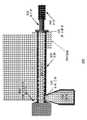
도 1은 예시적인 구현예에 따른 일례의 공동화 또는 유화 기계의 개략도를 제공한다.
도 2는 예시적인 구현예에 따른, 다수의 공동화 통과(pass)를 용이하게 하는 폐쇄 시스템과 열 제어 시스템을 추가로 포함하는 다른 예의 공동화 또는 유화 기계의 개략도를 제공한다.
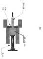
도 3a 내지 도 3e는 예시적인 구현예에 따른 일례의 압출기의 개략도를 제공한다.
도 4는 예시적인 구현예에 따른 일례의 제조 프로세스를 도시한 개략적인 흐름도를 제공한다.
도 5a 및 도 5b는 예시적인 구현예에 따른 공동화 프로세스 전(도 5a)과 공동화 프로세스 후(도 5b)의 은 입자의 현미경 이미지를 제공한다.
도 5c는 예시적인 구현예에 따른 공동화 프로세스 전("원료")과 공동화 프로세스 후("제품 재료")의 은 입자의 입자 크기 분포를 도시한다.
도 6a 및 도 6b는 예시적인 구현예에 따른 공동화 프로세스 전(도 6a)과 공동화 프로세스 후(도 6b)의 실리카 입자의 현미경 이미지를 제공한다.
도 6c는 예시적인 구현예에 따른 공동화 프로세스 전("원료")과 공동화 프로세스 후("제품 재료")의 실리카 입자의 입자 크기 분포를 도시한다.
도 7은 예시적인 구현예에 따른 공동화 프로세스 전("원료")과 공동화 프로세스 후("제품 재료")의 흑연 입자의 입자 크기 분포를 도시한다.
도 8은 예시적인 구현예에 따른 공동화 프로세스 전("원료")과 공동화 프로세스 후("제품 재료")의 그래핀(graphene) 입자의 입자 크기 분포를 도시한다.Those skilled in the relevant art will recognize that the drawings are for illustrative purposes only and are not intended to limit the scope of the claimed subject matter described herein. The drawings are not necessarily exhaustive; In some instances, various aspects of the claimed subject matter disclosed herein may be exaggerated or expanded to facilitate understanding of the different features. In the drawings, like reference characters generally refer to like features (e.g., functionally similar and / or structurally similar elements).
BRIEF DESCRIPTION OF THE DRAWINGS Figure 1 provides a schematic of an exemplary cavitation or emulsification machine according to an exemplary embodiment.
Figure 2 provides a schematic diagram of another example cavitation or emulsification machine, further comprising a closed system and a thermal control system to facilitate multiple cavitation passes, in accordance with an exemplary embodiment.
Figures 3A-3E provide a schematic diagram of an exemplary extruder according to an exemplary embodiment.
4 provides a schematic flow diagram illustrating an exemplary manufacturing process in accordance with an exemplary embodiment.
Figures 5A and 5B provide a microscope image of the silver particles before the cavitation process (Figure 5A) and after the cavitation process (Figure 5B) according to an exemplary embodiment.
Figure 5C shows the particle size distribution of silver particles before the cavitation process ("raw material") and after the cavitation process ("product material") according to an exemplary embodiment.
Figures 6a and 6b provide microscopic images of the silica particles before and after the cavitation process (Figure 6a) and after the cavitation process (Figure 6b) according to an exemplary embodiment.
Figure 6C shows the particle size distribution of the silica particles before the cavitation process ("raw material") and after the cavitation process ("product material") according to an exemplary embodiment.
Figure 7 shows the particle size distribution of graphite particles before the cavitation process ("raw material") and after the cavitation process ("product material") according to an exemplary embodiment.
Figure 8 shows the particle size distribution of graphene particles before the cavitation process ("raw material") and after the cavitation process ("product material") according to an exemplary embodiment.
이하의 내용은, 동수압적 공동화 장치를 사용하여 적층 가공하기에 적합한 재료를 제조하기 위한 시스템 및 방법과 관련된 다양한 개념 및 그 구현예에 관한 구체적인 설명이다. 개시된 개념이 임의의 특별한 구현 방법으로 제한되지 않기 때문에, 앞서서 설명하였고 이하에서 구체적으로 설명할 여러 가지 개념이 임의의 수 많은 방식으로 구현될 수 있다는 것을 이해하여야 한다. 구체적인 구현예 및 적용예의 예가 주로 설명 목적을 위해서 제공되었다.The following is a detailed description of various concepts and implementations related to a system and method for producing a material suitable for lamination using a hydrostatic cavitation apparatus. It is to be understood that the concepts described above are not limited to any particular implementation, and that various concepts described above and specifically to be described below may be implemented in any number of ways. Examples of specific implementations and applications are provided primarily for illustrative purposes.
공동화Cavitation
공동화는, 액체에 작용하는 힘의 결과로서 형성되는, 액체 내의 증기 공동(예를 들어, "기포" 또는 "공극"과 같이 액체가 없는 작은 구역)의 형성을 지칭할 수 있다. 일반적으로 그러한 프로세스는, 압력이 상대적으로 낮은 공동의 형성을 유발할 수 있는 급격한 압력 변화를 액체가 겪을 때 발생할 수 있다. 더 높은 압력에 노출될 때, 공극이 내파(implode)될 수 있고 강력한 충격파를 생성할 수 있다. 적용예에 따라서, 임의의 적합한 공동화 모드가 본원에서 제공된 방법 및 시스템에서 이용될 수 있다. 예를 들어, 일 구현예에서, 공동화 프로세스가 동수압적 공동화를 포함하거나, 동수압적 공동화일 수 있다.Cavitation can refer to the formation of a vapor cavity (e.g., a small area free of liquids, such as "bubbles" or "voids") in a liquid that is formed as a result of forces acting on the liquid. Generally such a process can occur when a liquid undergoes a sudden pressure change that can cause the formation of a relatively low pressure cavity. When exposed to higher pressures, voids can be imploded and generate strong shock waves. Depending on the application, any suitable cavitation mode may be used in the methods and systems provided herein. For example, in one embodiment, the cavitation process comprises hydrodynamic cavitation, or may be hydrodynamic cavitation.
동수압적 공동화는, 압력의 감소 및 후속되는 증가의 결과로서 유동 액체 내에서 발생하는 증기화, 기포 발생, 및 기포 내파의 프로세스를 지칭할 수 있다. 동수압적 공동화는 액체를 협소화된(constricted) 채널을 통해서 특정 속도로 통과시키는 것에 의해서 또는 액체를 통한 물체의 기계적인 회전에 의해서 생성될 수 있다. 협소화된 채널 및 시스템의 특정의(또는 특유의) 기하형태를 기초로 하는 경우에, 압력 및 운동 에너지의 조합이 높은 에너지의 공동화 기포를 생성하는 지역적인 협소화부 하류에 동수압적 공동화 공동(cavern)을 생성할 수 있다.Hydrostatic cavitation can refer to the process of vaporization, bubbling, and bubbling, which occur in a fluidized liquid as a result of a decrease in pressure and subsequent increase. Hydrostatic cavitation can be created by passing liquid through a constricted channel at a specific rate or by mechanical rotation of an object through the liquid. The combination of pressure and kinetic energy, when based on the narrowed channel and the specific (or specific) geometry of the system, results in a hydrostatic cavitation cavern downstream of the local narrowing zone, which creates a high energy cavitation bubble. Can be generated.
오리피스 및 벤투리 관이 공동화 생성을 위해서 이용될 수 있다. 벤투리 관이 이용될 수 있는데, 이는 벤투리 관의 매끄러운 수렴 및 발산 섹션 때문이며, 벤투리 관은 벤투리 관에 걸친 주어진 압력 강하를 위해서 목부(throat)에서 고속을 생성할 수 있다. 다른 한편으로, 오리피스가 파이프의 주어진 횡단면적 내에서보다 많은 수의 홀(홀의 보다 큰 둘레부)을 수용할 수 있다. 2가지 선택사항 모두가 가능하다.Orifices and venturi tubes can be used for cavitation generation. Venturi tubes can be used because of the smooth convergence and divergence sections of the venturi tubes, and the venturi tube can generate high speeds in the throat for a given pressure drop across the venturi tube. On the other hand, the orifices can accommodate a larger number of holes (larger circumferential portions of the holes) within a given cross-sectional area of the pipe. Both options are available.
기존의 공동화 시스템의 일부는 공동화 발생을 위해서 필요한 압력을 생성하기 위해서 대향하는 워터 제트를 이용하는 한편, 다른 시스템은 수압식 펌프 구동 및 진동(oscillating) 플런저에 의해서 압력 및 결과적인 진공을 생성하며, 플런저는 저점도 재료를 인입하고 이어서 저점도 재료를 특정 지점을 통해서 밀어내고, 그러한 특정 지점에서 공동이 발생된다. 그러나, 이러한 기존 시스템 중 어느 것도, 성분들을 분산시키기 위해서, 또는 탈-응집(de-agglomeration)을 통해 희망하는 입자 크기 분포를 획득하기 위해서, 유체의 점도보다 큰 점도를 가진 원료를 취급할 준비가 되어 있지 않다.Some of the existing cavitation systems utilize opposing water jets to create the pressure required for cavitation generation while other systems generate pressure and resulting vacuum by hydraulic pump actuation and oscillating plungers, Draws a low viscosity material and then pushes the low viscosity material through a particular point and cavities are generated at that particular point. However, none of these existing systems are ready to handle raw materials having viscosities greater than the viscosity of the fluid, in order to disperse the components, or to obtain the desired particle size distribution through de-agglomeration .
적층 가공Lamination processing
3차원(3D) 인쇄라고도 지칭되는 적층 가공은 디지털 모델로부터 3차원 입체 물체를 구성하기 위한 프로세스이다. 제품이 연속 층 증착을 통해 그 최종 형상으로 구성되기 때문에, 이 프로세스는 적층 가공으로 간주된다. 전통적인 기계 가공, 절삭, 드릴링, 연마 등과 같은 차감 프로세스는 일반적으로 사용되지 않는다. 일반적으로, 적층 가공은 세 가지 기술로 세분되며; 즉, 광조형, 융합 수지 압출 적층 조형(fused filament fabrication) 및 선택적 레이저 소결로 세분된다. 이러한 기술들은 각각 다른 유형의 원료를 사용할 수 있다. 아래에 더 논의된 바와 같이, 이 기술들 모두에 적합한 원료는 동수압적 공동화 프로세스를 이용하여 제조될 수 있다.Stacking, also referred to as three-dimensional (3D) printing, is a process for constructing a three-dimensional solid object from a digital model. Since the product is constructed in its final shape through continuous layer deposition, this process is considered to be a lamination process. Subtraction processes such as traditional machining, cutting, drilling, polishing, etc. are not commonly used. Generally, the lamination process is subdivided into three techniques; That is, it is subdivided into stereolithography, fused resin extrusion laminate formation (fused filament fabrication) and selective laser sintering. Each of these techniques can use different types of raw materials. As discussed further below, materials suitable for both of these techniques can be fabricated using a hydrostatic cavitation process.
광조형은 제품을 제조하기 위해 액체 원료를 사용하는 적층 가공 프로세스이다. 특히, 액체 자외선 경화성 광중합체 수지 통과 자외선 레이저가 제품의 연속 층을 구축하기 위해 사용된다. 각각의 층에 대하여, 레이저 빔은 액체 수지의 표면에 있는 부품 패턴의 단면을 추적한다. 자외선 레이저 광에 대한 노출은 수지에 추적된 패턴을 경화 및 응고시키며, 이 패턴을 하위 층에 결합한다. 제1 층은 액체 통 내의 엘리베이터 플랫폼 상에 지지될 수 있다.Stereolithography is a lamination process using liquid raw materials to manufacture products. In particular, liquid ultraviolet curable photopolymer resin passed ultraviolet lasers are used to build a continuous layer of product. For each layer, the laser beam tracks the cross section of the component pattern on the surface of the liquid resin. Exposure to ultraviolet laser light cures and coagulates the pattern traced to the resin and bonds this pattern to the underlying layer. The first layer can be supported on the elevator platform in the liquid canister.
패턴을 추적한 후, 엘리베이터 플랫폼은 약 0.05㎜ 내지 약 0.15㎜의 범위일 수 있는 한 층의 두께와 동일한 거리만큼 하강한다. 그 후, 수지로 충진된 블레이드가 부품의 단면을 가로질러 휩쓸면서 신선한 재료로 이를 코팅할 수 있다. 이 새로운 액체 표면에서, 후속 층 패턴이 레이저에 의해 추적됨으로써, 이 층을 선행 층에 결합한다. 완전한 제품이 형성될 때까지, 이 단계들이 반복될 수 있다.After tracing the pattern, the elevator platform descends by the same distance as the thickness of one layer, which can range from about 0.05 mm to about 0.15 mm. The resin-filled blades can then sweep across the cross-section of the part and coat it with fresh material. In this new liquid surface, the subsequent layer pattern is traced by the laser, thereby coupling this layer to the preceding layer. These steps can be repeated until a complete product is formed.
융합 수지 압출 적층 조형에서는, 노즐로부터 열가소성 중합체 (또는 열가소성 중합체 합성물)의 작은 비드를 압출함으로써, 제품 또는 부품이 제조된다. 원료의 필라멘트가 코일로부터 풀려서, 제어된 속도로 압출 노즐에 원료를 공급한다. 필라멘트가 압출될 때, 필라멘트의 원료를 연화하기 위해 노즐이 가열될 수 있다. 노즐은 수치 제어 기구에 의해 수평 및 수직 양 방향으로 이동할 수 있다. 노즐은 컴퓨터-지원 제조 소프트웨어 패키지에 의해 제어되는 공구-경로를 따르며, 부품은 한 번에 한 층씩 아래에서 위로 구축된다.In the fusion resin extrusion laminate molding, a product or a part is produced by extruding small beads of a thermoplastic polymer (or a thermoplastic polymer composition) from a nozzle. The filament of the raw material is released from the coil, and the raw material is supplied to the extrusion nozzle at a controlled speed. When the filaments are extruded, the nozzles can be heated to soften the raw material of the filaments. The nozzle can be moved both horizontally and vertically by a numerical control mechanism. The nozzles follow a tool-path controlled by a computer-aided manufacturing software package, and the components are built up one layer at a time from bottom to top.
선택적 레이저 소결은 광조형과 유사하게 이루어지만, 중요한 차이점이 있다. 먼저, 통에 담긴 액체 광중합체 대신, 선택적 레이저 소결에 사용되는 원료는 폴리스티렌, 세라믹, 유리, 나일론, 및 스틸, 티타늄, 알루미늄 및 은을 포함한 금속과 같은, 분말 재료를 함유한 베드 층(bed layer)이다. 고출력 레이저가 플라스틱, 금속, 세라믹 또는 유리 분말의 작은 입자를 희망하는 3차원 형상으로 선택적으로 융합하기 위해 표면을 가로질러 래스팅될 때, 베드는 분말을 특정 온도로 예열한다. 레이저는 분말 베드의 표면에 있는 부품의 3-D 디지털 성상으로부터(예를 들어, CAD 파일 또는 주사 데이터로부터) 생성된 단면을 주사함으로써 분말 재료를 선택적으로 융합한다. 각각의 단면이 주사된 후, 분말 베드가 한 층의 두께와 동일한 거리만큼 하강하며, 새로운 원료 층이 상부에 도포되고, 부품이 완성될 때까지 프로세스가 반복된다. 레이저가 분말을 타격할 때, 예를 들면, 소결에 의해, 분말이 그 지점에서 융합된다. 소결되지 않은 모든 분말은 그대로 유지되며, 물체의 지지 구조가 될 수 있다.Selective laser sintering is similar to stereolithography, but there are important differences. First, instead of the liquid photopolymer contained in the barrel, the raw materials used in the selective laser sintering include a bed layer containing a powder material such as polystyrene, ceramic, glass, nylon, and metals including steel, titanium, )to be. When the high power laser is laid across the surface to selectively fuse the small particles of plastic, metal, ceramic or glass powder into the desired three-dimensional shape, the bed preheats the powder to a certain temperature. The laser selectively fuses the powder material by scanning the generated cross-section from a 3-D digital image of the part on the surface of the powder bed (e.g., from a CAD file or scan data). After each cross section is scanned, the process is repeated until the powder bed is lowered by the same distance as the thickness of one layer, a new layer of raw material is applied to the top, and the part is completed. When the laser hits the powder, for example, by sintering, the powder fuses at that point. All powders that are not sintered remain intact and can be the supporting structure of an object.
원료(즉, 잉크, 페이스트, 필라멘트 등)는 원료의 평균 입자 크기를 줄이기 위해 응집체를 효율적으로 파괴함으로써 개선될 수 있다. 또한, 원료 내에 기능성 충진재를 효율적으로 분산시킴으로써, 보다 균일한 원료를 만들 수 있다. 후술하는 바와 같이, 작은 평균 입자 크기를 갖고 완벽하게 분산된 적층 가공용 원료를 제조하기 위해 동수압적 공동화 프로세스가 사용될 수 있다.Raw materials (i. E., Inks, pastes, filaments, etc.) can be improved by efficiently breaking agglomerates to reduce the average particle size of the raw material. Further, by efficiently dispersing the functional filler in the raw material, a more uniform raw material can be produced. As described below, a hydrostatic voiding process can be used to produce a fully dispersed batch processing feed having a small average particle size.
공동화 장비Hollowing equipment
적용예에 따라서, 공동화 또는 유화 프로세스를 실행할 수 있는 임의의 적합한 장비가 적층 가공용 재료를 제조하기 위해 이용될 수 있다. 도 1은 예시적 구현예에 따른 일례의 공동화 또는 유화 기계(1)의 개략도를 제공한다. 기계는 유입구(2) 및 배출구(3)를 포함한다. 기계(1)는 상업적으로 입수 가능한 공동화 기계일 수 있거나, 고객-맞춤형 설계의 공동화 기계일 수 있다. 예를 들면, 일부 구현예에서, 공동화 기계(1)는 BEE International에서 제작한 DeBEE 2000 공동화 기계, 또는 Microfluidics에서 제작한 M-110P일 수 있다. 원료를 기본적 공동화 기계(1) 내로 공급하도록 구성된, 본원에서 제공된 장치 시스템은, 예를 들어 유입구(2)에서 기본적 공동화 기계(1)에 부착되는 시스템을 지칭할 수 있다. 그 대신에, 본원에서 제공된 장치 시스템은, 도 1에 도시된 바와 같이, 기본적 공동화 기계(1) 및 부착된 시스템 모두의 조합을 포함하는 제조 시스템을 지칭할 수 있다.Depending on the application, any suitable equipment capable of carrying out the cavitation or emulsification process may be used to produce the material for the lamination. Figure 1 provides a schematic diagram of an exemplary cavitation or
도 1을 참조하면, 장치 시스템은 적어도 하나의 공급관(4), 공급관(4) 내의 원료(5), 및 재료를 공급관(4) 아래로 밀어서 재료를 기계(1)의 유입구(2) 내로 추진하는 피스톤(6)을 포함할 수 있다. 또한, 장치 시스템은 공급관(4)의 후방 단부 상에서 공기 밸브(7)를 포함하고, 그러한 공기 밸브(7)는 공급관(4) 내로의 압축 공기의 유동을 제어한다. 장치 시스템은 공기 라인(8)을 포함할 수 있고, 그러한 공기 라인은 압축 공기를 압축 공기의 공급원으로부터 공기 밸브(7) 내로 그리고 공급관(4) 내로 공급한다.1, a device system comprises at least one
기본적 공동화 기계(1)는, 적용예에 따라서, 임의의 적합한 구성요소를 포함할 수 있다. 예를 들어, 기본적 공동화 기계는 2개의 수압식 펌프를 포함할 수 있고, 그러한 수압식 펌프는 페이스트를, 매우 작은 오리피스를 통해서, 매우 작은 진공 챔버 내로, 그리고 특정의 희망 배압을 생성하는 다른 매우 작은 오리피스 외부로, 밀어내기 위해서 이용된다. 일 구현예에서, 작은 오리피스를 중간에서 진공 챔버와 이렇게 조합하는 곳에서 동수압적 공동화가 발생한다. 일부 구현예에서, 공동화 기계는 매우 작은 오리피스를 통해 원료를 도입하도록 구성된 다른 구성요소를 포함할 수 있다. 예를 들어, 공동화 기계는 수압식 펌프 또는 피스톤을 사용하지 않고 매우 작은 오리피스를 통해 원료를 주입하거나 밀어내도록 구성된 구성요소를 포함할 수 있다.The
또한, 기본적 공동화 기계(1)는 수압 저장용기(13), 수압 오일을 증압기(intensifier)(15)로 펌핑하기 위해서 펌프(17)를 작동시키는 모터(14)를 포함하고, 증압기는, 오리피스가 수용되고 공동화가 발생되는 공동화 챔버(9) 내로 재료가 추진될 수 있도록 하기 위해서, 볼 체크 시스템(12)이 폐쇄되어 있는 동안, 공동화 챔버(9) 내로 재료를 밀어내는 진동 플런저(11)를 구동한다. 증압기(15)가 플런저(11)를 전방으로 밀 때, 증압기(15)의 전방부 내의 수압 오일이 질소 백(16)에 대항하여 밀리게 된다. 플런저(11)가 완전 작동 위치에 도달한 후에, 위치결정 센서가 증압기(15)를 구동하는 수압식 펌프(17)를 정지시키고, 압력이 질소 백(16)에 대항하여 축적되어, 플런저(11)가 그 시작 위치로 다시 밀려나도록 유도한다.The
적용예에 따라서, 공급관의 수를 포함하는, 구성들이 달라질 수 있다. 일 구현예에서, 원료를 수용한 작은 단일 공급관이, 공동화 기계를 각각 통과한 후에 테스트될 수 있는 작은 배치(batch)를 위해서 이용될 수 있다. 또한, 공동화 기계(1)는 공급관(4)에 열을 인가하도록 구성된 제1 가열 요소(20)와 공동화 챔버(9)에 열을 인가하도록 구성된 제2 가열 요소(22)를 포함할 수 있다. 일부 구현예에서, 공동화 기계(1)는 제1 가열 요소(20)만을 포함할 수 있다. 다른 구현예에서, 공동화 기계(1)는 제2 가열 요소(22)만을 포함할 수 있다. 다른 구현예에서, 공동화 기계(1)는 제1 가열 요소(20)와 제2 가열 요소(22)를 모두 포함할 수 있다. 일부 구현예에서, 제1 가열 요소(20)와 제2 가열 요소(22)는 공급관(4)과 공동화 챔버(9)에 각각 배치된 저항 히터 또는 가열 랩(heating wrap)일 수 있다. 가열 요소(20, 22)들은 공동화 기계(1) 내부에 있는 원료의 온도를 약 0℃ 내지 약 700℃의 범위 이내로 만들도록 구성될 수 있다. 일부 구현예에서, 가열 요소들은 원료를 그 유리 전이 온도보다 약 50℃ 내지 약 100℃ 높은 범위 내의 온도로 만들도록 구성될 수 있다.Depending on the application, configurations may vary, including the number of feed tubes. In one embodiment, a small single feed line that receives raw material can be used for a small batch that can be tested after each pass through the cavitation machine. The
다른 구현예에서, 다른 유형의 가열 요소가 사용될 수 있다. 예를 들어, 제1 가열 요소(20)와 제2 가열 요소(22)를 구현하기 위해 집속된 방사 에너지(예를 들면, 마이크로파, 적외선, 전파 등)가 사용될 수 있다. 다른 구현예에서, 가열 요소(20, 22)들은 "워터 재킷"을 제공하기 위해 가열될 부분들이 노와 같은 챔버 내에 봉입되는 침지식 시스템으로 형성될 수 있다. 챔버는 가열될 공동화 기계(1)의 부분의 형상과 일치하는 고체, 액체 또는 기체를 포함할 수 있다. 일부 구현예에서, 보조 재료를 사용하면, 용융 또는 비등과 같은 상전이시 온도가 실질적으로 일정하게 유지될 수 있기 때문에, 보다 정밀한 온도 제어가 가능해질 수 있다. 일부 구현예에서, 챔버는 공동화 시스템의 가열되는 부분을 둘러싸는 고체, 액체 또는 가스 매체를 포함하고 있는 더 작은 챔버를 노와 같은 외측 챔버가 봉입하고 있는 "러시아 인형"의 구성을 가질 수도 있다. 이러한 시스템에 사용되는 일반적인 기체는 공기, 질소, 희가스, 스팀 등을 포함할 수 있다. 일반적인 액체는 물, 비점이 비교적 높은 용매, 또는 플라스틱 또는 금속과 같은 용융된 재료를 포함할 수 있다. 일부 구현예에서, 용융시키지 않고 공동화 기계(1)의 형상과 일치하도록 하기 위해 열 전도성 분말과 같은 고체 재료가 사용될 수 있다. 또 다른 구현예에서, 챔버는 가스 및/또는 전기 가열 요소를 사용하여 가열될 수 있다. 열은 대류, 전도 및/또는 복사를 통해 노에서 주변 고체, 액체 또는 기체로 전달될 수 있다. 마찬가지로, 열은 이 메커니즘들을 통해 공동화 기계로 전달될 것이다.In other embodiments, other types of heating elements may be used. For example, focused radiant energy (e.g., microwave, infrared, radio waves, etc.) may be used to implement the
일부 구현예에서, 추가적인 가열 요소가 사용될 수 있다. 예를 들어, 가열 요소(20, 22)와 접촉하는 것으로 도시된 부분들 이외의 공동화 기계의 추가적인 부분을 가열하는 것이 바람직할 수 있다. 이러한 추가적인 가열 요소는 종래의 가열 재킷, 인쇄된 후막 저항 히터, 또는 대류, 전도 및/또는 복사를 이용한 다른 가열 기술을 포함하여, 전술한 기술들 중 임의의 기술을 사용하여 구현될 수 있다.In some embodiments, additional heating elements may be used. For example, it may be desirable to heat additional portions of the cavitation machine other than those shown as contacting the
도 2는 예시적인 구현예에 따른, 다수의 공동화 통과를 용이하게 하는 폐쇄 시스템과 열 제어 시스템을 추가로 포함하는 다른 예의 공동화 또는 유화 기계(201)의 개략도를 제공한다. 열 제어 시스템은 재료가 공동화 프로세스를 빠져나가는 직후에 직렬로 열 교환기(209)를 포함할 수 있다. 열 교환기(209) 이후에 열전쌍(210)이 후속될(하류에 위치될) 수 있고, 그러한 열전쌍은 재료가 열 교환기(209)를 통과한 후 재료의 온도를 판독하도록 구성된다. 급냉수(chilled water)가 적어도 하나의 워터 밸브(211)를 이용하여 열 교환기로 제공될 수 있으며, 그러한 워터 밸브는 물이 급냉수 공급원(214)으로부터 물 배관(212)을 경유하여 열 교환기(209)로, 열 교환기(209)를 통해서, 이어서 열 교환기(209) 외부로 그리고 다시 물 배관(213)을 경유하여 냉각수의 복귀 물 연결부로 유동할 수 있게 한다. 도 2에 도시되지는 않았으나, 열 제어 시스템은 공동화 챔버와 접촉하여 배치된 가열 요소와 아울러, (도 1에 도시된 가열 요소(20)와 유사한) 관(204, 215)과 접촉하여 배치된 가열 요소를 포함할 수도 있다.FIG. 2 provides a schematic diagram of another example cavitation or
물의 유동은, 수동으로 또는, 예를 들어 소프트웨어 프로그램에 의해서, 자동적으로 제어될 수 있다. 일 구현예에서, 미리 결정된 온도가 소프트웨어 프로그램에 입력될 수 있으며, 그러한 소프트웨어 프로그램은, 실행될 때, 적어도 하나의 프로세서로 하여금 열 제어 시스템을 실행하도록 유도한다. 다른 구현예에서, 열전쌍(210)으로부터의 피드백이 소프트웨어로 하여금 워터 밸브(211)를 조정하게 할 수 있으며, 그에 따라 열 제어 시스템을 빠져나가는 재료의 온도가 희망하는 범위 내에 있게 된다. 일부 구현예에서, 시스템은 시스템 내의 다른 영역에서 재료의 온도를 측정하기 위해 추가적인 열전쌍을 포함할 수 있다. 예를 들어, 추가적인 열전쌍은 3-방향 밸브(218)로 유입되는 재료의 온도, 공동화 챔버를 빠져나가는 재료의 온도 및 열 교환기(209)를 빠져나가는 재료의 온도를 측정하도록 구성될 수 있다. 이러한 모든 열전쌍으로부터의 출력은 급냉수의 유동이나 도 1에 도시된 가열 요소(20, 22)와 같은 가열 요소를 이용한 열의 인가를 제어하기 위해 사용될 수 있다. 일 구현예에서, 재료는 하나의 구분된(discrete) 통과로 가공된다. 이어서, 희망하는 제품 재료 성질을 달성하기 위해 필요한 만큼의 많은 통과를 위해서, 관들이 상호 교환되고 프로세스가 반복될 수 있다.The flow of water can be controlled manually, or automatically, for example, by a software program. In one implementation, a predetermined temperature may be input to the software program, which, when executed, directs the at least one processor to execute the thermal control system. In other implementations, feedback from the thermocouple 210 may cause the software to adjust the
복수의 공동화 통과를 허용하며/또는 용이하게 하는 폐쇄된 시스템이 도 2에도 도시되어 있다. 열 제어 시스템으로부터 더 하류에 위치하는 폐쇄 시스템은 제2 공급관; 동수압적 공동화 프로세스를 반복하기 위해 제품 재료를 동수압적 공동화 챔버 내로 다시 재공급하도록 구성된 복수의 2-방향 밸브 및 3-방향 밸브; 및 2개의 압력 변환기를 추가로 포함할 수 있다. 이 구현예는 전술한 작은 규모(예를 들어, 연구개발(R & D))의 구현예보다 대규모 생산에 적합할 수 있다. 본원에서 설명되는 폐쇄된 시스템의 하나의 장점은 오염(예를 들어, 공기)에 대한 노출의 감소(예를 들어, 완벽한 제거)이다.A closed system that allows and / or facilitates multiple cavitation passes is also shown in FIG. The closed system located further downstream from the thermal control system comprises a second supply pipe; A plurality of two-way valves and three-way valves configured to re-supply product material back into the hydrostatic bubble chamber to repeat the hydrostatic bore process; And two pressure transducers. This embodiment may be suitable for larger scale production than the above-mentioned small scale implementations (e.g., R & D). One advantage of the closed system described herein is the reduction in exposure to contamination (e.g., air) (e.g., complete removal).
폐쇄 시스템은 열 교환기(209)를 빠져나간 이후 재료가 이동하는 방향과 아울러, 시스템으로 밀려 들어오는 재료의 방향을 제어하는 2-방향 밸브(216, 217)를 포함한다. 시스템은 재료가 공동화 기계(201)로 이동하게 하기 위해 2-방향 밸브(216, 217)와 바람직하게 동기화된 3-방향 밸브(218)를 추가로 포함할 수 있다. 일 구현예에서, 관(204) 내의 재료가 공기 구동형 피스톤(206)에 의해 관 아래로 추진될 때, 재료가 해당 밸브를 통과하여 3-방향 밸브(218)로 이동하도록, 2-방향 밸브(216)가 반드시 폐쇄되어야 한다. 재료가 관(204) 내에 있을 때, 3-방향 밸브(218)는 재료가 관(204)으로부터 공동화 기계(1) 내로 이동하도록 허용한다.The closed system includes a two-
공동화가 발생한 후에, 재료는 열 제어 시스템을 통과하여 열 교환기(209)의 외부로 이동하게 되고, 열전쌍(210)을 통과한다. 이러한 지점에서, 재료가 개방된 2-방향 밸브(217)를 통해서 그리고 관(215) 내로 이동하여, 공기-구동형 피스톤을 관의 후방부를 향해서 관 아래로 밀고, 그러한 관의 후방부에서는 공기 밸브(220)가 공기를 관(215) 내의 피스톤으로 공급한다. 관(204)으로부터 관(215)으로의 이러한 재료 이동의 프로세스 중에, 공기 밸브(220)가 개방되고, 그에 따라, 관(215)이 재료로 충진되고 피스톤(206)이 관(215)의 후방부를 향해서 추진됨에 따라 공기가 관(215)의 외부로 밀려날 수 있다. 관(204)이 비어 있을 때, 내부의 피스톤(206)이 관(204)의 전방부를 타격하고, 기계 내로 추진되는 재료 상으로는 더 이상의 압력이 가해지지 않는다. 일부 구현예에서, 시스템 내부의 압력이, 가공되는 원료의 성질에 따라, 약 200psi 내지 약 45,000psi의 범위로 유지되도록 제어될 수 있다.After the cavitation occurs, the material passes through the thermal control system, moves out of the heat exchanger 209, and passes through the thermocouple 210. At this point, the material moves through the open two-
3-방향 밸브에 의해서 기계의 유입구 근처에 위치되는 압력 변환기(219)가 이러한 압력 강하를 소프트웨어로 전송할 수 있고, 이어서, 소프트웨어는 적어도 하나의 프로세서로 하여금 2-방향 밸브 및 3-방향 밸브를 절환(switch)시키도록 유도하고, 그에 따라 재료가 관(215)으로부터 다시 공동화 기계(201)를 통해서 그리고 다시 관(204) 내로 이동하게 될 것이다. 재료가 관(215)으로부터 공동화 기계(201)로 이동하도록 밸브가 일단 절환되면(217은 폐쇄되고, 216은 개방되며, 218은 절환된다), 공기 밸브(220)가 자동적으로 턴 온(turn on)되고 피스톤(206) 및 재료를 전체 프로세스를 통해서 관(215) 아래로 그리고 다시 관(204)으로 추진할 수 있다.A
조작자/사용자는 재료가 공동화 기계(201)를 통과하게 될 횟수를 선택할 수 있으며, 그에 의해서 공동화 및/또는 (열 제어 시스템에 의한) 냉각 프로세스를 반복할 수 있다. 일 구현예에서, 미리 결정된 수의 통과가 이루어진 후에, 시스템뿐만 아니라 밸브 및 피스톤을 구동하는 공기가 자동적으로 차단될 수 있다. 이러한 안전 특징(feature)은 현재의 사이클이 완료되면 공기 압력을 해제할 수 있다. 일 구현예에서, 본원에서 설명된 시스템 구성은, 희망하는 동작 압력(들) 및 온도(들)에서 특정 횟수의 통과 이후에 희망하는 결과가 성취되었는지를 결정하기 위해서 임의 시간에 재료의 샘플을 취할 수 있도록 허용한다.The operator / user can select the number of times the material will pass through the
일 구현예에서, 본원에서 제공된 장치 시스템은, 프로세스 내의 몇몇 지점에서 재료의 온도를 결정하고, 공동화가 발생된 직후에 직렬로 연결되는 열 교환기로의 급냉수의 유동과 아울러 가열 요소를 제어하는 워터 밸브를 작동시키기 위해서 이용되는 소프트웨어 및 몇 개의 열전쌍 중 적어도 하나에 의해 재료의 온도를 제어할 수 있다. 일 구현예에서, 재료가 안정적으로 유지되도록 그리고 다음 사이클 또는 통과를 위해서 준비되도록, 가공되는 재료에 적합한 범위로 그 온도를 감소시키기 위해서, 재료가 공동화 이후에 냉각된다. 일부 구현예에서, 열 제어 시스템은 재료의 열 분해 온도를 초과하지 않도록 가열 요소와 워터 밸브를 제어할 수 있다. 상술한 바와 같이, 기계(201)는 페이스트, 분말 및 필라멘트와 같이 적층 가공 프로세스에서 사용될 수 있는 다양한 재료를 프로세싱하기 위해 사용될 수 있다. 일부 구현예에서, 기계가 페이스트를 프로세싱하기 위해 사용될 경우, 원료의 온도는 약 10℃ 내지 약 50℃의 범위로 유지될 수 있다. 용매 없이 열가소성 플라스틱을 프로세싱하는 경우, 기계(201)에서의 원료의 온도는 원료 내의 중합체의 유리 전이 온도보다 약 25℃ 내지 약 100℃ 높은 온도로 제어될 수 있다. 일부 구현예에서, 더 큰 분자량을 가진 원료 또는 갈래 중합체를 포함한 원료의 경우, 더 높은 온도가 필요할 수 있다. 따라서, 일부 구현예에서, 기계(201)에서의 원료의 온도는 원료의 다양한 특성에 따라 약 0℃ 내지 약 700℃ 범위 이내로 제어될 수 있다.In one embodiment, the device system provided herein is configured to determine the temperature of the material at several points in the process, and to control the flow of quench water to the heat exchanger that is connected in series immediately after the cavitation occurs, The temperature of the material can be controlled by at least one of several thermocouples and software used to operate the valve. In one embodiment, the material is cooled after cavitation to reduce the temperature to a range suitable for the material being processed so that the material remains stable and ready for the next cycle or pass. In some embodiments, the thermal control system may control the heating element and the water valve such that the thermal decomposition temperature of the material is not exceeded. As discussed above, the
도 2에 도시된 온도 제어 시스템이 없는 경우에, 적어도 하나의 구현예에서의 재료가 너무 많은 열을 보유할 수 있으며, 각각의 통과를 통해서 점점 더 많은 열 에너지를 획득할 수 있고, 이에 따라 그 성분의 일부를 손상시키는 결과를 초래할 수 있다. 시행 착오 및/또는 매개변수에 관한 연구를 통해 각각의 재료에 대해서 결정될 수 있는 압력 및 온도에 대해 설정된 매개변수로 재료가 프로세싱될 때, 고점도 잉크, 페이스트, 슬러리 또는 나노-입자의 분산체(dispersion)를 위한 매체를 준비하는데 있어서, 로트별(lot to lot) 제품의 항상성이 임의의 다른 기존의 프로세스보다 놀랍도록 훨씬 더 우수하다. 본원에서 설명된 장치 시스템 및 방법에 의한 공동화 프로세스를 통해서 연속적이고 제어된 방식으로 중간 점도 내지 고점도 재료를 이동시킬 수 있는 능력은 기존 방법에서 예상되지 않았다.In the absence of the temperature control system shown in FIG. 2, the material in at least one embodiment can have too much heat and can acquire more and more heat energy through each pass, May result in damage to some of the components. When materials are processed with parameters set for the pressure and temperature that can be determined for each material through studies on trial and error and / or parameters, the viscosity of the high viscosity ink, paste, slurry or dispersion of nano- ), The homeostasis of lot-lot products is far superior to any other conventional process, surprisingly. The ability to move medium viscosity or highly viscous materials in a continuous and controlled manner through the cavitation process by the device systems and methods described herein has not been anticipated in existing methods.
도 3a 내지 도 3e는 예시적인 구현예에 따른 일례의 압출기의 개략도를 제공한다. 도 3a를 참조하면, 압출기(300)는 공동화된 재료를 융합 수지 압출 적층 조형 프로세스에서 사용될 수 있는 필라멘트와 같은 다양한 형상으로 형성하기 위해 사용될 수 있다. 재료는 호퍼(301)로부터 공급 목부(feedthroat)(302)를 통해 배럴(304)로 유입된다. 스크류 드라이브 공급 목부(303)가 배럴(304) 내에서 스크류(305)를 회전시킴으로써, 배럴(304)을 통해 히터(306) 측으로 재료를 밀어낸다. 히터(306)에 의해 인가되는 열로 인해, 재료가 연화되고 용융될 수 있다. 재료를 여과하는데 도움을 줄 수 있는 파쇄기 판(307)을 통해, 재료가 공급관(308) 내로 가압된다. 마지막으로, 재료는 희망하는 형상으로 재료를 형성하도록 구성된 다이(309)를 통과한다. 일부 구현예에서, 다이(309)는 미리 결정된 직경을 가진 필라멘트로 재료를 형성하도록 구성된다. 다른 구현예에서, 다이(309)는 중공관 또는 시트로 재료를 형성하기 위해 사용될 수 있다. 일부 구현예에서, 재료는 다이(309)를 통과한 후 그 용융 온도 미만의 온도로 냉각될 수 있다.Figures 3A-3E provide a schematic diagram of an exemplary extruder according to an exemplary embodiment. Referring to FIG. 3A, the
일부 구현예에서, 장치 시스템은 (예를 들어, 도 1 및 도 2에 도시된 공동화 기계와 같은) 공동화 기계와 도 3a에 도시된 압출기(300)를 모두 포함할 수 있다. 공동화 기계(1)에 의해 처리된 제품 재료가 압출기(300)의 호퍼(301)로 공급될 수 있으며, 전술한 바와 같이 원하는 형상으로 형성될 수 있다. 다른 구현예에서, 공동화 기계(1)는 압출기(300)의 일부를 대체할 수 있다. 예를 들면, 공동화 기계(1)는 호퍼(301), 공급 목부(302), 스크류 드라이브 공급 목부(303), 배럴(304), 스크류(305) 및 히터(306)를 대체할 수 있다. 제품 재료는 공동화 기계(1) 내에서 가열 및 가압될 수 있으며, 파쇄기 판(307)을 통해 공급관(308) 내로 그리고 다이(309)를 통해 직접 밀려날 수 있다. 따라서, 공동화된 제품 재료의 압력이 압출기(300)를 통해 제품 재료를 추진하기 위해 사용될 수 있다. 일부 구현예에서, 다이(309)는 공동화 기계에 부착된 용기로부터 제품 재료를 수취할 수 있다. 예를 들어, 압출기(300)는 공동화 기계에 장착될 수 있다. 일부 구현예에서, 압출기는 도 1에 도시된 공동화 챔버(9)와 고압 실린더(10) 사이에 있는 한 지점에서 공동화 기계에 장착될 수 있다. 이러한 구성은 제품 재료가 고압을 받는 구현예에서 유용할 수 있다. 일부 다른 구현예에서, 압출기(300)는 도 1에 도시된 공동화 챔버(9)로부터 하류에 있는 한 지점에서 공동화 기계에 장착될 수 있다. 이러한 구성은 제품 재료가 저압을 받는 구현예에서 유용할 수 있다. 일부 구현예에서, 압출기(300)는 R&B Plastics, Davis Standard, Olympia, ESI, Plastic Machinery Equipment, Sterling, Farrel, Egan, 및 Polytruder와 같은 제조사로부터 입수할 수 있는 상업적으로 입수 가능한 압출기일 수 있다.In some embodiments, the apparatus system may include both a hollowing machine (e.g., such as the hollowing machine shown in Figures 1 and 2) and an
제품 재료를 희망하는 형상으로 형성하기 위해 다양한 압출 기술이 사용될 수 있다. 직접 압출 프로세스에서 사용될 수 있는 일례의 압출기(320)가 도 3b에 도시되어 있다. 순방향 압출이라고도 지칭되는 직접 압출에서는, 램(322)이 다이(326)를 통해 제품 재료(324)를 가압하여 압출된 형상(328)을 형성한다. 램(322)은 도 3a에 도시된 스크류(305)의 목적과 유사한 목적에 부응한다. 이러한 프로세스 중에, 제품 재료(324)가 고정된 용기 벽체에 대항하여 미끄러진다. 그 결과, 용기와 제품 재료 간의 마찰이 높아질 수 있다. 제품 재료의 직경보다 약간 작은 직경의 더미 블록이 열간 압출에서 제품 재료의 산화를 방지하기 위해 사용될 수 있다. 관과 같은 중공부가, 후술하는 바와 같이, 직접 압출을 이용하여 압출될 수도 있다.Various extrusion techniques may be used to form the product material into the desired shape. An
도 3c는 중공의 압출된 형상으로 제품 재료를 형성하기 위해 사용될 수 있는 일례의 압출기(330)를 도시하고 있다. 제품 재료(334)는 맨드릴(336)의 주위에 중공 형상으로 형성될 수 있다. 램(332)이 다이(338)를 통해 제품 재료(334)와 맨드릴(336)을 밀어낼 때, 제품 재료(334)가 중공 형상으로 형성되며, 맨드릴(336)을 코팅한다. 맨드릴(336)은 다이(338)의 입구까지 연장한다. 맨드릴(336)과 다이(338)의 벽체 사이의 간격이 압출된 관의 벽체 두께를 결정한다. 맨드릴(336)은 압출로 동심 관들을 제조하기 위해 램(332)과 함께 이동하도록 제작된다. 또한, 맨드릴(336)은 제품 재료(334)로 코팅될 재료일 수 있다. 이 방법은 가끔 오버재킷 압출이라 지칭된다. 일부 구현예에서, 중공의 압출된 형상이 되도록, 맨드릴(336)은 후에 제거될 수 있다.Figure 3c shows an
도 3d는 간접 압출 프로세스에서 사용될 수 있는 일례의 압출기(340)를 도시하고 있다. 역방향 압출이라고도 지칭되는 간접 압출은 제품 재료(344)를 압출된 형상(349)으로 형성하기 위해 제품 재료(344)의 방향과는 반대 방향으로 램(342)이 운동하는 프로세스이다. 따라서, 용기와 제품 재료(344) 간에 상대 운동이 존재하지 않는다. 또한, 마찰도 작기 때문에, 직접 압출에 비해 간접 압출에는 작은 힘이 필요할 수 있다. 중실 부품을 압출하기 위해서는, 도 3d에 도시된 램(342)과 같은 중공 램이 필요하다. 중공 압출을 위해서는, 중실 램과 용기 벽체 사이의 환형 공간을 통해 제품 재료(344)가 추진될 수 있다.Figure 3d shows an
도 3e는 정수압적 압출 프로세스에서 사용될 수 있는 일례의 압출기(350)를 도시하고 있다. 정수압적 압출에서는, 용기(358)가 유체(356)로 충진된다. 유체를 통해 제품 재료(354)로 압출 압력이 전달된다. 용기(358)의 벽체와 제품 재료(354) 사이에 접촉이 없기 때문에, 이 프로세스에서는 마찰이 제거될 수 있다. 그 결과, 이 프로세스를 사용하여 취성 제품 재료가 압출될 수 있다. 일부 구현예에서, 취성이 강한 제품 재료가 압력 챔버로 압출될 수 있다. 용기(358), 램(352) 및 다이(360)의 강도에 의해 압력이 제한된다. 피마자유와 같은 식물성 오일이 유체(356)로서 사용될 수 있다. 일부 구현예에서, 이 프로세스는 실온에서 수행될 수 있다. 일부 구현예에서, 압출 이외의 기술이 희망하는 형상으로 제품 재료를 형성하기 위해 사용될 수도 있다. 예를 들어, 희망하는 형상을 성취하기 위해 사출 성형, 슬롯 다이 코팅, 또는 제품 재료의 기계 가공이 사용될 수 있다.Figure 3e illustrates an
전술한 바와 같이, 일부 구현예에서, 도 1 및 도 2에 도시된 공동화 기계와 같은 공동화 기계가 도 3a 내지 도 3e에 도시된 압출기와 같은 압출기에 접속될 수 있다. 일부 구현예에서, 공동화 기계는 압출기의 구성요소의 일부를 대체할 수 있다. 예를 들면, 제품 재료가 공동화 프로세스의 결과로서 고압을 받을 수 있으며, 압출 다이를 통해 제품 재료를 밀어내기 위해 램 또는 스크류를 사용하는 대신, 이 압력이 압출 다이를 통해 제품 재료를 밀어내는 역할을 할 수 있다. 일부 구현예에서, 다이는 압출 용기에 용접되거나, 스웨이지 고정(swage locked)되거나, 나사 결합될 수 있으며, 용기는 공동화 기계에 용접되거나, 스웨이지 고정되거나, 나사 결합될 수 있다.As noted above, in some embodiments, a hollowing machine, such as the hollowing machine shown in Figures 1 and 2, may be connected to an extruder, such as the extruder shown in Figures 3A-3E. In some embodiments, the hollowing machine may replace some of the components of the extruder. For example, instead of using a ram or screw to push product material through an extrusion die, the product material may be subjected to high pressures as a result of the cavitation process, and this pressure may play a role in pushing product material through the extrusion die can do. In some embodiments, the die may be welded, swaged locked, or threaded to an extrusion vessel, and the vessel may be welded, swaged, or threaded to a hollowing machine.
도 4는 예시적인 구현예에 따른 일례의 제조 프로세스(400)를 도시한 개략적인 흐름도를 제공한다. 일부 구현예에서, 프로세스(400)는 선택적 레이저 소결 제조에서 사용하기 위한 분말 재료, 광조형에서 사용하기 위한 잉크 또는 페이스트, 또는 융합 수지 압출 적층 조형에서 사용하기 위한 필라멘트를 제조하기 위해 사용될 수 있다. 요약하면, 프로세스(400)는 제1 온도와 제1 압력에 원료를 노출시키는 단계(단계 405)와, 제품 재료를 제조하기 위해 원료에 대해 공동화 프로세스를 실시하는 단계(단계 410)를 포함한다. 또한, 프로세스(400)는 제품 재료를 희망하는 형상으로 형성하는 선택적 단계(단계 415), 제품 재료를 냉각시키는 선택적 단계(단계 420) 및/또는 용매를 제거하기 위해 제품 재료를 건조시키는 선택적 단계(단계 425)를 포함할 수 있다.FIG. 4 provides a schematic flow diagram illustrating an
도 4를 계속 참조하면, 보다 상세하게, 프로세스(400)는 원료가 노출 후에 제2 점도를 갖도록, 제1 온도와 제1 압력에 대해 제1 점도를 가진 원료를 노출시키는 것을 포함한다(단계 405). 원료는 도 1 및 도 2에 도시된 공동화 기계와 같은 공동화 시스템에 부착되는 엔지니어링 공동화 공급관 내로 장입될 수 있다. 그 후 공급 관 내의 피스톤이 공급관을 따라 구동되어, 제1 압력을 달성하도록 원료를 가압할 수 있다. 일부 구현예에서, 공급관과 접촉하는 가열 요소가 제1 온도를 달성하기 위해 사용될 수 있다.4, in more detail, the
원료는 복수의 입자를 포함할 수 있다. 입자는 형상 및 크기를 포함하는 임의의 기하형태를 가질 수 있다. 예를 들어, 입자는, 구형, 시트, 플레이크(flake), 프릿(frit), 타원형, 또는 불규칙적인 형상을 포함하는 형상을 가질 수 있다. 입자는 임의 크기일 수 있다. 본원에서 언급된 "크기"라는 용어는, 문맥에 따라서 그리고 입자의 기하형태에 따라서, 직경, 반경, 길이, 폭, 높이 등을 지칭할 수 있다. 복수의 입자를 설명하기 위해서 "크기"라는 용어가 이용될 때, 그러한 크기는 복수의 크기의 평균 크기를 지칭할 수 있다.The raw material may include a plurality of particles. The particles may have any geometric shape including shape and size. For example, the particles may have a shape including a sphere, sheet, flake, frit, ellipse, or irregular shape. The particles can be of any size. The term " size "as referred to herein may refer to diameter, radius, length, width, height, etc., depending on the context and geometry of the particle. When the term "size" is used to describe a plurality of particles, such a size may refer to an average size of a plurality of sizes.
일부 구현예에서, 원료는 하나 이상의 구조적, 전기적, 열적 및 미적 특성에 기초하여 선택된 기능성 재료를 포함할 수 있다. 예를 들어, 전기 절연성(즉, 세라믹) 또는 전기 전도성(즉, 금속)인 기능성 재료는 전자 장치의 제조에 사용될 페이스트의 제조에 유용할 수 있다. 기능성 재료는 그 색상, 항복 강도, 인장 강도, 또는 광조형 제조를 사용하여 제작된 제품 재료로 형성될 부품과 관련될 수 있는 임의의 다른 재료 특성에 기초하여 선택될 수도 있다.In some embodiments, the raw material may comprise a functional material selected based on one or more structural, electrical, thermal, and aesthetic properties. For example, a functional material that is electrically insulating (i.e., ceramic) or electrically conductive (i.e., metal) may be useful in the manufacture of a paste to be used in the manufacture of electronic devices. The functional material may be selected based on its color, yield strength, tensile strength, or any other material properties that may be associated with the part to be formed from the product material made using photo-fabrication.
기능성 재료는 원료 내에서 제1 평균 입자 크기를 가질 수 있다. 일부 구현예에서, 원료 내에서 기능성 재료의 1차 입자 크기는 약 1 나노미터 내지 약 100 미크론의 범위일 수 있다. 그러나, 응집으로 인하여, 원료 내에서 기능성 재료의 평균 입자 크기는 원료 내에서 기능성 재료의 1차 입자 크기보다 훨씬 클 수 있다.The functional material may have a first average particle size in the raw material. In some embodiments, the primary particle size of the functional material in the feed may range from about 1 nanometer to about 100 microns. However, due to agglomeration, the average particle size of the functional material in the raw material may be much larger than the primary particle size of the functional material in the raw material.
도 5a를 참조하면, 은 분말을 포함한 원료의 현미경 이미지가 도시되어 있다. 알 수 있는 바와 같이, 은 입자의 1차 평균 크기보다 평균 크기가 상당히 큰 응집체로 작은 은 입자들이 군집되어 있다. 마찬가지로, 도 6a는 실리카 입자를 포함한 원료의 현미경 이미지를 도시하고 있다. (도면에 큰 흑점으로 표시된) 몇몇 응집체를 볼 수 있다. 도 5a 및 도 6a에 도시된 원료의 예는 단지 예시를 위한 것이며, 많은 다른 기능성 재료가 사용될 수도 있다.Referring to FIG. 5A, a microscope image of a raw material containing silver powder is shown. As can be seen, small silver particles are clustered into agglomerates with a mean size significantly larger than the primary average size of the silver particles. Similarly, FIG. 6A shows a microscope image of a raw material containing silica particles. Some agglomerates (denoted by large black spots in the figure) can be seen. Examples of the raw materials shown in Figs. 5A and 6A are for illustrative purposes only, and many other functional materials may be used.
도 4에 도시된 프로세스(400)를 다시 참조하면, 일부 구현예에서, 기능성 재료는 분말을 포함할 수 있으며, 원료는 용매를 추가로 포함할 수 있다. 일부 구현예에서, 원료는 하나 이상의 분산제, 하나 이상의 계면 활성제 및 하나 이상의 충진제를 포함할 수 있다. 예를 들어, 일부 구현예에서, 프로세스(400)는 중합체로 코팅된 충진제 또는 중합체와 충진제의 혼합물을 포함한 원료에 대해 실시될 수 있다. 다른 구현예에서, 원료 내의 분말은 혼합된 금속들의 공융 혼합물을 포함할 수 있다. 또 다른 구현예에서, 원료 내의 분말은 금속, 유리 또는 중합체와 혼합된 세라믹 입자를 포함할 수 있다. 원료의 성분은 원료 내에서 분산 및/또는 건조될 수 있는 분말의 능력에 기초하여 선택될 수 있다.Referring again to process 400 shown in FIG. 4, in some embodiments, the functional material may comprise a powder, and the raw material may further comprise a solvent. In some embodiments, the feedstock may comprise one or more dispersants, one or more surfactants, and one or more fillers. For example, in some embodiments, the
프로세스(400)에 사용되는 원료 내에 포함될 수 있는 용매의 비-제한적인 예에는 다음 중 어느 하나가 포함된다: 폴리에틸렌(pe), 폴리프로필렌(pp), 폴리스티렌(ps), 폴리우레탄(pu), 폴리비닐 아세테이트(pva), 폴리비닐 부티랄(pvb), 폴리비닐 클로라이드(pvc), 아크릴로니트릴 부타디엔 스티렌(abs), 아크릴(pma, ibma, pbm, pmma), 셀룰로오스(에틸셀룰로오스, 메틸셀룰로오스, 하이드록시프로필셀룰로오스 등) 셀룰로이드, 셀룰로오스 아세테이트, 폴리사카라이드(전분, 키토산, ha 등), 폴리락트 산(pla, plla), 폴리글리콜 산(pga), 시클로올레핀 코폴리머(coc), 에틸렌-비닐 아세테이트(eva), 에틸렌 비닐 알콜(evoh), 플루오로플라스틱(fep, pfa, ctfe, ectfe, etfe와 함께, ptfe) 이오노머, kydex(등록 상표 아크릴/pvc 합금), 액정 폴리머(lcp), 폴리아세탈(pom 또는 아세탈), 폴리아크릴레이트(아크릴), 폴리아크릴로니트릴(pan 또는 아크릴로니트릴), 폴리아미드(pa 또는 나일론), 폴리이미드(pi), 폴리아미드-이미드(pai), 폴리아릴에테르케톤(peak 또는 케톤), 폴리부타디엔(pbd), 폴리부틸렌(pb), 폴리부틸렌 테레프탈레이트(pbt), 폴리카프로락톤(pcl), 폴리클로로트리플루오로에틸렌(pctfe), 폴리에틸렌 테레프탈레이트(pet), 폴리시클로헥실렌 디메틸렌 테레프탈레이트(pct), 폴리카보네이트(pc), 폴리하이드 록시알카노에이트(phas), 폴리케톤(pk), 폴리에스테르, 폴리에테르에테르케톤(peek), 폴리에테르케톤케톤(pekk), 폴리에테르이미드(pei), 폴리에테르설폰(pes), 폴리설폰폴리에틸렌클로리네이트(pec), 폴리메틸펜텐(pmp), 폴리페닐렌 옥사이드(ppo), 폴리페닐렌 설파이드(pps), 폴리프탈아미드(ppa), 폴리술폰(psu), 폴리트리메틸렌 테레프탈레이트(ptt), 폴리비닐리덴 클로라이드(pvdc), 폴리(알킬렌 카보네이트) 코폴리머 및 스티렌-아크릴로니트릴(san).Non-limiting examples of solvents that may be included in the raw materials used in process 400 include any of the following: polyethylene (pe), polypropylene (pp), polystyrene (ps), polyurethane (pu) Polyvinyl butyral (pvb), polyvinyl chloride (pvc), acrylonitrile butadiene styrene (abs), acrylic (pma, ibma, pbm, pmma), cellulose (ethyl cellulose, methyl cellulose, Cellulose acetate, polysaccharide (starch, chitosan, ha), polylactic acid (pla, plla), polyglycolic acid (pga), cycloolefin copolymer (coc), ethylene- (EVA), ethylene vinyl alcohol (EVOH), fluoroplastics (fep, pfa, ctfe, ectfe, etfe with ptfe) ionomer, kydex (registered acrylic / pvc alloy), liquid crystal polymer (lcp) (pom or acetal), polyacrylate (Acrylate), polyacrylonitrile (pan or acrylonitrile), polyamide (pa or nylon), polyimide (pi), polyamide-imide (pai), polyaryl ether ketone (Pbt), polybutylene (pb), polybutylene terephthalate (pbt), polycaprolactone (pcl), polychlorotrifluoroethylene (pctfe), polyethylene terephthalate (pet), polycyclohexylene di (Pct), polycarbonate (pc), polyhydroxyalkanoate (phas), polyketone (pk), polyester, polyetheretherketone (peek), polyetherketoneketone (pekk) (Pts), polyethersulfone (pes), polysulfone polyethylene chlorinate (pec), polymethylpentene (pmp), polyphenylene oxide (ppo), polyphenylene sulfide ), Polysulfone (psu), polytrimethylene terephthalate (ptt), polyvinyl (Pvdc), poly (alkylene carbonate) copolymers and styrene-acrylonitrile (san).
프로세스(400)에 사용되는 원료에 포함될 수 있는 충진재는 혼합물, 화합물, 합금, 순수한 형태의 염, 귀금속, 희토류 금속, 알칼리 금속 및 전이 금속을 포함할 수 있다. 예를 들어, 다음의 요소들 중 어느 하나가 원료 내의 충진재로서 사용될 수 있다: 리튬, 나트륨, 칼륨, 루비듐, 세슘, 프란시움, 베릴륨, 마그네슘, 칼슘, 스트론튬, 바륨, 스칸듐, 티탄, 바나듐, 크롬, 망간, 철, 코발트, 니켈, 구리, 아연, 이트륨, 지르코늄, 니오브, 몰리브덴, 테크네튬, 루테늄, 로듐, 팔라듐, 은, 카드뮴, 하프늄, 탄탈륨, 텅스텐, 레늄, 오스뮴, 이리듐, 백금, 금, 수은, 러더포듐, 두브늄, 시보??, 보륨, 하슘, 코페르니슘, 알루미늄, 갈륨, 인듐, 주석, 탈륨, 납, 비스무트, 폴로늄, 란타늄, 세륨, 프라세오디뮴, 네오디뮴, 프로메튬, 사마륨, 유로퓸, 가돌리늄, 테르븀, 디스프로슘, 홀뮴, 에르븀, 툴륨, 이테르븀, 루테튬, 악티늄, 토륨, 프로트악티늄, 우라늄, 넵투늄, 플루토늄, 아메리슘, 큐륨, 버클륨, 캘리포늄, 아인시타이늄, 페르뮴, 멘델레븀, 노벨륨, 로렌슘, 게르마늄, 비소, 안티몬, 아스타틴. 특히, 다음의 물질들이 프로세스(400)의 다양한 구현예에서 충진재로서 사용될 수 있다: 알루미늄 마그네슘 붕화물, 알루미늄 산화물, 알루미늄 산질화물, 알루미늄 질화물, 바륨 스트론튬 코발트 페라이트, 바륨 티탄산염, 베릴륨 산화물, 비스무트 스트론튬 칼슘, 구리 산화물, 비스무트 티탄산염, 본 차이나, 질화 붕소, 브리퀘테지(briquetage), 알루민산 칼슘, 탄산 칼슘, 산화 칼슘, 인산 칼슘, 티탄산 칼슘, 세노스피어(cenosphere), 세라믹 착색제, 세라믹 플럭스, 세라믹 발포체, 세라믹 매트릭스 복합재, 세륨 헥사보라이드, (안정화되고 순수한) 세륨 산화물, 코우드 스톤, 크리터졸, 디스프로슘 티탄산, 도기, 일렉트로세라믹, 팽창 점토 골재, 강유전체 세라믹, 내화 점토, 프릿, 건식 실리카, 지오폴리머, 지오폴리머 콘크리트, 이산화 게르마늄, 유리, 유리-세라믹, 그로그(점토), 이붕산 하프늄, 하이드록시아파타이트, 제스모나이트, 카올린/카올리나이트, 란타늄 갈륨 실리케이트, 란타늄 헥사보라이드, 란타늄 스트론튬 코발트 페라이트, 란타늄 스트론튬 망가나이트, 납 산화물, 리드 스칸듐 탄탈레이트, 리드 지르콘 티탄네이트, 루미세라, 이붕화 마그네슘, 마그네슘 산화물, 마르텐사이트, 나일 실트, 마그네슘 산화물, 마그네슘 티탄테이트 멕스 페이스, 금속 점토, 몰리브덴 디실리사이드, 진흙, 도자기, 종이 점토, 석영, 바다 도기, 사이알론, 실리카흄, 실리콘 붕화물, 실리콘 탄화물, 실리콘 이산화물, 실리콘 질화물, 실리콘 산질화물, 동석, 세라믹 고용체, 스트론튬 티타네이트, 정방 다결정 지르코니아, 티탄 탄화물, 티탄 이산화물, 튜브-기반 나노구조, 텅스텐 탄화물, 텅스텐 디실리사이드, 텅스텐 질화물, 초고온 세라믹, 용화 자기, 이트륨 바륨 구리 산화물, 이트륨 산화물, 아연 산화물, 지르코니아로 강화된 알루미나, (순수하고 안정화된) 지르코늄 산화물,,,, 티탄, 크롬, 망간.Fillers that may be included in the raw materials used in the
또한, 원료는 최종 부품을 형성하기 위해, 예를 들면, 최종 부품에서 희망하는 다공률을 달성하기 위해, 적층 가공 기술이 사용된 후에 제거될 수 있는 이탈성 재료(fugitive material)를 포함할 수 있다. 이탈성 재료는 주변 매트릭스를 방해하지 않고 약화되거나 제거될 수 있는 성분을 포함할 수 있다. 예를 들면, 염과 같은 물질은 용해될 수 있는 반면, 다당류, 카본 블랙, 흑연 등의 물질은 다른 기술에 의해 열 분해되거나 제거될 수 있다.The raw material may also include a fugitive material that can be removed to form the final part, for example, after the lamination technique is used to achieve the desired porosity in the final part . The deblocking material may include components that can be weakened or removed without interfering with the surrounding matrix. For example, materials such as salts can be dissolved while materials such as polysaccharides, carbon black, graphite and the like can be thermally decomposed or removed by other techniques.
프로세스(400)에 사용되는 원료 내에 포함될 수 있는 용매의 비-제한적인 예에는 다음 중 어느 하나가 포함된다: 아세트산, 아세톤, 아세토니트릴, 벤젠, 부탄올, 부틸 아세테이트, 사염화탄소, 클로로벤젠, 클로로포름, 시클로헥산, 1,2-디클로로에탄 디에틸 에테르, 디에틸렌 글리콜, 디글라임(디에틸렌 글리콜 디메틸에테르), 1,2-디메톡시-에탄(글라임, DME), 디메틸에테르 디메틸-포름아미드(DMF), 디메틸 설폭사이드(DMSO), 디옥산, 에탄올, 에틸 아세테이트, 에틸렌 글리콜, 감마부티로락톤(GBL), 글리세린, 헵탄, 헥사메틸포스포아미드(HMPA), 헥사메틸포스포러스 트리아미드(HMPT), 헥산, 메탄올, 메틸 t-부틸 에테르(MTBE), 메틸렌 클로라이드, N-메틸-2-피롤리디논(NMP), 니트로메탄, 펜탄, 페트롤늄 에테르, 프로판올, 프로필렌 카보네이트, 피리딘, 테르피네올, 테트라히드로푸란(THF), 텍사놀, 톨루엔, 트리에틸 아민, 물 및 크실렌.Non-limiting examples of solvents that may be included in the raw materials used in
프로세스(400)에 사용되는 원료 내에 포함될 수 있는 계면 활성제의 비-제한적인 예에는 다음 중 어느 하나가 포함된다: 음이온성(카르복실레이트, 포스페이트 에스테르, 설포네이트, 페트롤륨 술포네이트, 알킬벤젠술포네이트, 나프탈렌술포네이트, 올레핀 술포네이트, 알킬 설페이트, 설페이트, 황산화 천연 오일 및 지방, 황산화 에스테르, 황산화 알카놀아미드, 알킬 페놀, 에톡실화된 및 황산화된 등), 비이온성(에톡실화된 지방족 알코올, 폴리옥시에틸렌 계면 활성제, 카르복실 에스테르, 폴리에틸렌 글리콜 에스테르, 안히드로소르비톨 에스테르 및 에톡실화된 유도체, 지방산의 글리콜 에스테르, 카르복실 아미드, 모노알칸올아민 축합물, 폴리옥시에틸렌 지방산 아미드 등), 양이온성(사차 암모늄염, 아민 아미드 결합, 폴리옥시에틸렌 알킬 및 지환족 아민, n,n,n',n'테트라키스 치환 에틸렌디아민, 2-알킬-1-하이드록시에틸-2-이미다졸린 등) 및 양쪽성(n-코코-3-아미노프로피오닉 산/나트륨 염, n-탈로우 3-이미노디프로피오네이트, 디소듐 염, n-카르복시메틸 n-디메틸 n-9 옥타디세닐 암모늄 하이드록사이드, n-코코아미드에틸 n-하이드록시에틸글리신, 나트륨 염 등).Non-limiting examples of surfactants that may be included in the raw materials used in
또한, 원료는 기능성 재료, 분산제, 결합제 및 담체를 포함한 혼합물을 포함할 수 있다. 일부 구현예에서, 원료는 하나 이상의 용매를 포함할 수도 있다. 예를 들어, 원료 내의 중합체의 유리 전이 온도 미만의 온도에서 원료가 유동할 수 있도록 하기 위해, 원료에 용매가 첨가될 수 있다. 일부 구현예에서, 생성된 제품 재료가 광 복사에 의해 경화될 수 있도록 하기 위해, 원료의 적어도 하나의 성분 재료는 감광성일 수 있다.The raw material may also comprise a mixture comprising a functional material, a dispersant, a binder and a carrier. In some embodiments, the feedstock may comprise one or more solvents. For example, a solvent may be added to the feedstock to allow the feedstock to flow at a temperature below the glass transition temperature of the polymer in the feedstock. In some embodiments, the at least one component material of the raw material may be photosensitive so that the resulting product material can be cured by photo-radiation.
원료는 하나 이상의 구조적, 전기적, 열적 및 미적 특성에 기초하여 선택된 적어도 하나의 기능성 재료와 중합체를 포함한 혼합물을 포함할 수 있다. 기능성 재료는 원료 내에서 제1 평균 입자 크기를 가질 수 있다. 일부 구현예에서, 원료 내에서 기능성 재료의 1차 입자 크기는 약 1 나노미터 내지 약 100 미크론의 범위일 수 있다. 그러나, 응집으로 인하여, 원료 내에서 기능성 재료의 평균 입자 크기는 원료 내에서 기능성 재료의 1차 입자 크기보다 훨씬 클 수 있다. 원료에 포함된 기능성 재료와 중합체는 전술한 기능성 재료와 폴리머 중 어느 하나를 포함할 수 있다. 예를 들면, 원료 내의 중합체는 폴리에틸렌, 폴리프로필렌, 아세탈, 아크릴, 나일론, 폴리스티렌, 폴리비닐 클로라이드, 아크릴로니트릴 부타디엔 스티렌 및 폴리카보네이트를 포함할 수 있다. 기능성 재료는 금속, 세라믹, 중합체, 나노튜브, 나노와이어, 나노플라트넷 및 기타 재료를 포함할 수 있다.The raw material may comprise a mixture comprising at least one functional material and a polymer selected on the basis of one or more structural, electrical, thermal and aesthetic properties. The functional material may have a first average particle size in the raw material. In some embodiments, the primary particle size of the functional material in the feed may range from about 1 nanometer to about 100 microns. However, due to agglomeration, the average particle size of the functional material in the raw material may be much larger than the primary particle size of the functional material in the raw material. The functional material and polymer contained in the raw material may include any one of the above-described functional material and polymer. For example, the polymer in the raw material may include polyethylene, polypropylene, acetal, acrylic, nylon, polystyrene, polyvinyl chloride, acrylonitrile butadiene styrene and polycarbonate. Functional materials may include metals, ceramics, polymers, nanotubes, nanowires, nanoflatents, and other materials.
원료 혼합물에 포함될 수 있는 기능성 재료는 전술한 재료 중 어느 하나를 포함할 수 있다. 일부 구현예에서, 은, 실리카, 알루미나, 질화 붕소, 질화 알루미늄, 유리 프릿, 그래핀, 흑연, 팔라듐, 루테늄, 금, 백금, 지르코니아 및/또는 티타니아가 기능성 재료로서 사용될 수 있다. 이 재료들은 분말 형태로 용이하게 사용될 수 있다. 잉크 또는 페이스트를 형성하기 위해, 이러한 기능성 분말 재료들은, 예를 들어, PVB, 셀룰로오스, 폴리(알킬렌 카보네이트) 코폴리머 또는 PVA와 함께 혼합될 수 있다. 중합체는 테르피네올, 텍사놀, 톨루엔, MEK, 프로필렌 카보네이트, 글리콜 혼합물 또는 물과 같은 호환 가능한 용매에 용해될 수 있다. 필라멘트를 제조하기 위해, 기능성 분말 재료는 아크릴로니트릴 부타디엔 스티렌(ABS), 폴리락트산(PLA), 폴리카보네이트(PC), 폴리아미드(PA), 폴리스티렌(PS), 리그닌 또는 고무와 혼합될 수 있다.The functional material that may be included in the raw material mixture may include any of the above-mentioned materials. In some embodiments, silver, silica, alumina, boron nitride, aluminum nitride, glass frit, graphene, graphite, palladium, ruthenium, gold, platinum, zirconia and / or titania may be used as the functional material. These materials can be readily used in powder form. In order to form an ink or paste, these functional powder materials can be mixed together with, for example, PVB, cellulose, poly (alkylene carbonate) copolymer or PVA. The polymer may be dissolved in a compatible solvent such as terpineol, tezanol, toluene, MEK, propylene carbonate, glycol mixture or water. For the production of filaments, the functional powder material may be mixed with acrylonitrile butadiene styrene (ABS), polylactic acid (PLA), polycarbonate (PC), polyamide (PA), polystyrene (PS), lignin or rubber .
일부 구현예에서, 원료를 형성하는 모든 성분 재료는 실질적으로 동시에 공동화 기계에 도입될 수 있다. 또한, 원료를 형성하는 성분들은 원료 내에 기능성 재료가 분산되기 전에 공동화 기계에 첨가될 수 있다. 따라서, 원료의 성분들은 모두 어떤 탈-응집 또는 분산이 실시되기 전에 공동화 기계에 도입될 수 있다.In some embodiments, all of the ingredient materials that form the raw material may be introduced into the cavitation machine at substantially the same time. In addition, the ingredients forming the raw material may be added to the hollowing machine before the functional material is dispersed in the raw material. Thus, the ingredients of the feedstock can all be introduced into the cavitation machine before any de-agglomeration or dispersion takes place.
제2 점도가 공동화 내로 밀려나는 원료에 있어서 중요할 수 있기 때문에, 본원에서 설명된 제조 방법은, 제2 점도를 성취하기 위한 적절한 제1 압력 및 제1 온도를 결정하는 것을 추가로 포함할 수 있다. 그러한 결정은 매개변수에 관한 연구 및/또는 시행착오를 포함할 수 있다. 그러한 결정은, 원료 내에서 이용되는 상이한 성분 재료들의 재료 성질을 포함하는 특정 알고리즘 또는 컴퓨터 데이터베이스를 이용하는 것에 의해서 최적화될 수 있다.Because the second viscosity may be important for the raw material being pushed into the cavitation, the manufacturing process described herein may further include determining a suitable first pressure and a first temperature for achieving the second viscosity . Such a determination may involve studying parameters and / or trial and error. Such determinations can be optimized by using a specific algorithm or computer database that includes the material properties of the different component materials used in the raw material.
제1 온도 및 제1 압력이 가공 조건 및 재료 성질에 따라 달라진다. 일 구현예에서, 제1 온도는 약 20℃ 내지 약 100℃ - 예를 들어, 약 25℃ 내지 약 80℃, 약 30℃ 내지 약 60℃, 약 35℃ 내지 약 50℃, 약 40℃ 내지 약 50℃ 등일 수 있다. 적용예에 따라서, 다른 값도 가능하다.The first temperature and the first pressure are dependent on the processing conditions and material properties. In one embodiment, the first temperature is from about 20 째 C to about 100 째 C, such as from about 25 째 C to about 80 째 C, from about 30 째 C to about 60 째 C, from about 35 째 C to about 50 째 C, 50 ° C, and the like. Depending on the application, other values are possible.
일 구현예에서, 제1 압력은 100psi 내지 약 100,000psi - 예를 들어, 500psi 내지 약 80,000psi, 1,000psi 내지 약 50,000psi, 2.000psi 내지 약 10,000psi, 3,000psi 내지 약 5,000psi, 등일 수 있다. 적용예에 따라서, 다른 값도 가능하다.In one embodiment, the first pressure may be from 100 psi to about 100,000 psi, for example, from 500 psi to about 80,000 psi, from 1,000 psi to about 50,000 psi, from 2.000 psi to about 10,000 psi, from 3,000 psi to about 5,000 psi, Depending on the application, other values are possible.
본원에서 설명된 방법의 일 구현예에서, 실온에서의 제1 점도는 적어도 약 1Kcps - 예를 들어, 적어도 약 5Kcps, 약 10Kcps, 약 20Kcps, 약 40Kcps, 약 60Kcps, 약 80Kcps, 약 100Kcps, 약 150Kcps, 약 200Kcps, 약 250Kcps, 약 300Kcps, 약 350Kcps, 약 400Kcps, 약 500Kcps, 약 600Kcps, 약 700Kcps, 약 800Kcps, 약 900Kcps, 약 1000Kcps, 또는 그 초과일 수 있다. 제1 점도에 대한 상한선은 없다. 본원에서 설명된 방법 및 시스템이 기존의 공동화 기술에 의해서 가공되는 저점도 재료를 취급하도록 준비됨에 따라, 제1 점도에 대한 하한선도 없다.In one embodiment of the methods described herein, the first viscosity at room temperature is at least about 1 Kcps, such as at least about 5 Kcps, about 10 Kcps, about 20 Kcps, about 40 Kcps, about 60 Kcps, about 80 Kcps, about 100 Kcps, , About 200 Kcps, about 250 Kcps, about 300 Kcps, about 350 Kcps, about 400 Kcps, about 500 Kcps, about 600 Kcps, about 700 Kcps, about 800 Kcps, about 900 Kcps, about 1000 Kcps, or more. There is no upper limit for the first viscosity. As the methods and systems described herein are prepared to handle low viscosity materials processed by conventional cavitation techniques, there is no lower limit for the first viscosity.
일반적으로, 제2 점도는 제1 점도보다 낮을 수 있는데, 이는 적어도 부분적으로 원료를 제1 온도 및 제1 압력에 노출하는 프로세스 때문이다. 제2 점도는 재료에 따라서 달라지고 또한 제1 압력 및 제1 온도에 따라서 달라진다. 예를 들어, 제2 점도는 제1 점도의 약 10% 내지 약 90% - 예를 들어, 제1 점도의 약 20% 내지 약 80%, 약 30% 내지 약 70%, 약 40% 내지 약 60%, 약 45% 내지 약 55% 등일 수 있다. 일 구현예에서, 제2 점도는 제1 점도의 약 25% 내지 약 50%이다.Generally, the second viscosity may be lower than the first viscosity, at least in part because of the process of exposing the feedstock to the first temperature and the first pressure. The second viscosity varies with the material and also depends on the first pressure and the first temperature. For example, the second viscosity may range from about 10% to about 90% of the first viscosity - e.g., from about 20% to about 80%, from about 30% to about 70%, from about 40% %, About 45% to about 55%, and the like. In one embodiment, the second viscosity is from about 25% to about 50% of the first viscosity.
프로세스(400)는 제3 점도를 가진 제품 재료를 제조하기 위해 원료에 대해 동수압적 공동화 프로세스를 실시하는 단계를 포함하며, 공동화 챔버 내에서 원료에 대해 동수압적 공동화 프로세스가 실시될 때, 원료는 제2 온도에 노출된다(단계 410). 일부 구현예에서, 원료에 대해 실시되는 공동화 프로세스는 기능성 재료를 효율적으로 탈-응집함과 동시에 기능성 재료를 제품 재료 전체에 분산시킬 수 있다. 기능성 재료의 동시 탈-응집과 분산은, 통상적으로, 광조형용 페이스트를 제조하기 위한 종래 기술을 이용해서는 수행될 수 없다. 밀링과 같은 종래 기술은 수성 유제를 파쇄할 수 있고, 기포를 포집할 수 있으며, 장쇄 중합체를 파괴할 수 있으므로, 저급한 제품 재료를 제조하게 된다. 그 결과, 기능성 재료를 분산시키기 위한 프로세스와는 별도로, 기능성 재료를 탈-응집시키기 위한 프로세스가 실시되어야만 한다. 대조적으로, 프로세스(400)는 기능성 재료의 탈-응집과 분산이 공동화 기계 내에서 하나의 단계에서 실시될 수 있도록 한다. 일부 구현예에서, 공동화 챔버와 접촉하는 가열 요소가 공동화 챔버 내의 재료를 희망하는 온도로 가열하기 위해 사용될 수 있다.The
(제품 재료의) 제3 점도는 일반적으로 제1 점도보다 낮을 수 있다. 제3 점도는 재료에 따라서 달라지고 또한 재료에 가해진 가공 조건에 따라서 달라진다. 예를 들어, 제2 점도는 대략적으로 제1 점도의 약 90% 미만 - 예를 들어, 약 80% 미만, 약 75%, 약 70%, 약 65%, 약 60%, 약 55%, 약 50%, 약 45%, 약 40%, 약 35%,약 30%, 또는 그 미만일 수 있다. 일 구현예에서, 제3 점도는 제1 점도의 약 50%이다. 일부 경우에, 일단 압력이 해제되고/또는 제품 재료의 온도가 냉각되면, 제3 점도는 제2 점도보다 크다.The third viscosity (of the product material) may generally be lower than the first viscosity. The third viscosity varies with the material and also depends on the processing conditions applied to the material. For example, the second viscosity may be less than about 90%, such as less than about 80%, about 75%, about 70%, about 65%, about 60%, about 55% , About 45%, about 40%, about 35%, about 30%, or less. In one embodiment, the third viscosity is about 50% of the first viscosity. In some cases, once the pressure is released and / or the temperature of the product material is cooled, the third viscosity is greater than the second viscosity.
제품 재료 내의 기능성 재료는 원료 내의 기능성 재료의 제1 평균 입자 크기보다 작은 제2 평균 입자 크기를 가질 수 있다. 예를 들어, 공동화 프로세스는 원료 내의 응집체를 파괴할 수 있으며, 이에 따라, 평균 입자 크기를 감소시킨다. 일부 구현예에서, 제품 재료 내에서의 입자의 평균 크기는 1차 입자 크기와 실질적으로 동일할 수 있다.The functional material in the product material may have a second average particle size that is less than the first average particle size of the functional material in the raw material. For example, the cavitation process can destroy aggregates in the feedstock, thereby reducing the average particle size. In some embodiments, the average size of the particles in the product material may be substantially the same as the primary particle size.
도 5b는 은 입자를 포함한 원료에 대해 동수압적 공동화 프로세스를 실시하기 전후의 입자들 간의 대비를 도시하고 있다. 도시된 바와 같이, 제품 재료에는 응집체가 실질적으로 존재하지 않는다. 시각적으로 관찰 가능한 입자의 응집이 제품 재료에서 관찰되지 않도록, 입자들이 분산되어 있다. 도 5c는 공동화 프로세스 전("원료")과 공동화 프로세스 후("제품 재료")의 은 입자의 입자 크기 분포를 도시하고 있다. 505로 표시된 선은 원료에서의 입자 크기 분포를 나타내고, 510으로 표시된 선은 제품 재료를 제조하기 위해 원료가 공동화된 후의 입자 크기 분포를 나타낸다. 도시된 바와 같이, 원료 내의 입자의 명목 크기는 약 4 미크론이지만, 원료는 약 13 미크론의 명목 크기를 가진 (즉, 제품 재료의 2%인) 응집체도 포함한다. 원료에 대해 공동화 프로세스가 실시된 후, 생성된 제품 재료는 약 4 미크론의 명목 입자 크기를 가지며, 효율적으로 탈-응집되었다.Figure 5b shows the contrast between the particles before and after the hydrostatic voiding process is performed on the raw material containing the silver particles. As shown, the product material is substantially free of aggregates. The particles are dispersed so that visually observable aggregation of the particles is not observed in the product material. Figure 5c shows the particle size distribution of the silver particles before the cavitation process ("raw material") and after the cavitation process ("product material"). The line denoted by 505 represents the particle size distribution in the raw material, and the line denoted by 510 represents the particle size distribution after the raw material is hollowed to produce the product material. As shown, the nominal size of the particles in the feed is about 4 microns, but the feed also includes agglomerates having a nominal size of about 13 microns (i.e., 2% of the product material). After the cavitation process was performed on the raw material, the resulting product material had a nominal particle size of about 4 microns and was effectively de-agglomerated.
도 6b는 실리카 입자를 포함한 원료에 대해 동수압적 공동화 프로세스를 실시하기 전후의 입자들 간의 대비를 도시하고 있다. 도시된 바와 같이, 제품 재료에는 응집체가 실질적으로 존재하지 않는다. 도 6c는 예시적인 구현예에 따른 공동화 프로세스 전("원료")과 공동화 프로세스 후("제품 재료")의 실리카 입자의 입자 크기 분포를 도시하고 있다. 605로 표시된 선은 원료에서의 입자 크기 분포를 나타내고, 610으로 표시된 선은 제품 재료를 제조하기 위해 원료가 공동화된 후의 입자 크기 분포를 나타낸다. 도시된 바와 같이, 원료 내의 입자의 명목 크기는 약 0.15 미크론이며, 최대 크기는 약 0.5 미크론이다. 원료에 대해 공동화 프로세스가 실시된 후, 생성된 제품 재료는 약 0.1 미크론의 명목 입자 크기와 약 0.25 미크론의 최대 입자 크기를 갖는다.Figure 6b shows the contrast between the particles before and after carrying out hydrodynamic cavitation processes on the raw material containing silica particles. As shown, the product material is substantially free of aggregates. Figure 6C shows the particle size distribution of the silica particles before the cavitation process ("raw material") and after the cavitation process ("product material") according to an exemplary embodiment. The line denoted by 605 represents the particle size distribution in the raw material, and the line denoted by 610 represents the particle size distribution after the raw material is hollowed to produce the product material. As shown, the nominal size of the particles in the raw material is about 0.15 microns and the maximum size is about 0.5 microns. After the cavitation process is performed on the raw material, the resulting product material has a nominal particle size of about 0.1 microns and a maximum particle size of about 0.25 microns.
도 7은 예시적인 구현예에 따른 공동화 프로세스 전("원료")과 공동화 프로세스 후("제품 재료")의 흑연 입자의 입자 크기 분포를 도시하고 있다. 705로 표시된 선은 원료에서의 입자 크기 분포를 나타내고, 710으로 표시된 선은 제품 재료를 제조하기 위해 원료가 공동화된 후의 입자 크기 분포를 나타낸다. 도시된 바와 같이, 원료 내의 입자의 명목 크기는 약 2 미크론이며, 최대 크기는 약 10 미크론이다. 원료에 대해 공동화 프로세스가 실시된 후, 생성된 제품 재료는 약 1 미크론의 명목 입자 크기와 약 3 미크론의 최대 입자 크기를 갖는다.Figure 7 shows the particle size distribution of graphite particles before the cavitation process ("raw material") and after the cavitation process ("product material") according to an exemplary embodiment. The line denoted by 705 represents the particle size distribution in the raw material, and the line denoted by 710 represents the particle size distribution after the raw material is hollowed to produce the product material. As shown, the nominal size of the particles in the raw material is about 2 microns and the maximum size is about 10 microns. After the cavitation process is performed on the raw material, the resulting product material has a nominal particle size of about 1 micron and a maximum particle size of about 3 microns.
도 8은 예시적인 구현예에 따른 공동화 프로세스 전("원료")과 공동화 프로세스 후("제품 재료")의 그래핀 입자의 입자 크기 분포를 도시하고 있다. 805로 표시된 선은 원료에서의 입자 크기 분포를 나타내고, 810으로 표시된 선은 제품 재료를 제조하기 위해 원료가 공동화된 후의 입자 크기 분포를 나타낸다. 도시된 바와 같이, 원료 내의 입자의 명목 크기는 약 8 미크론이며, 최대 크기는 약 13 미크론이다. 원료에 대해 공동화 프로세스가 실시된 후, 생성된 제품 재료는 약 1.5 미크론의 명목 입자 크기와 약 4 미크론의 최대 입자 크기를 갖는다.Figure 8 shows the particle size distribution of graphene grains before the cavitation process ("raw material") and after the cavitation process ("product material") according to an exemplary embodiment. The line denoted by 805 represents the particle size distribution in the raw material, and the line denoted by 810 represents the particle size distribution after the raw material is hollowed to produce the product material. As shown, the nominal size of the particles in the raw material is about 8 microns and the maximum size is about 13 microns. After the cavitation process is performed on the raw material, the resulting product material has a nominal particle size of about 1.5 microns and a maximum particle size of about 4 microns.
일부 구현예에서, 본원에 기재된 장치 시스템은 원료가 다수회 공동화 프로세스를 거치도록 할 수 있다. 공동화 기계를 통한 다수의 통과는 희망하는 수준의 제품 재료의 탈-응집 또는 점도를 달성하기 위해 유용할 수 있다. 일부 구현예에서, 통과 횟수가 미리 결정될 수 있다. 일부 구현예에서, 통과 횟수는 원료 내의 입자들의 크기, 그들의 농도, 그들의 조성 및 주변 매트릭스의 특성(예를 들면, 입자들 사이의 분자간 힘, 그리고 입자와 매트릭스 사이의 분자간 힘)에 기초하여 선택될 수 있다. 일부 구현예에서, 약 10 미크론 초과의 직경을 가진 입자의 경우, 1회의 통과면 충분할 수 있다. 약 1 내지 10 미크론 사이의 직경을 가진 입자의 경우, 1 내지 3회의 통과면 충분할 수 있다. 약 500 나노미터 내지 1 미크론 사이의 직경을 가진 입자의 경우, 2 내지 4회의 통과면 충분할 수 있다. 약 500 나노미터 미만의 직경을 가진 입자의 경우, 5 내지 7회의 통과면 충분할 수 있다. 일부 구현예에서, 60 중량%의 은 충진 조성물을 포함한 원료의 경우, 3회의 통과면 충분할 수 있다. 93%의 은 충진 조성물을 포함한 원료의 경우, 입자를 완전히 탈-응집시키기 위해 8 내지 10회의 통과가 필요할 수 있다. 필요한 통과 횟수는 주어진 양의 제품 재료를 제조하기 위한 시간의 양을 결정할 수도 있다. 예를 들어, 일부 구현예에서, 분당 약 0.25 리터 내지 분당 약 6 리터의 속도로 제품 재료를 제조하기 위해 원료가 공동화된다. 다른 속도도 가능할 수 있다.In some embodiments, the device system described herein may cause the feedstock to undergo a plurality of cavitation processes. Multiple passes through the hollowing machine may be useful to achieve the desired level of de-agglomeration or viscosity of the product material. In some implementations, the number of passes may be predetermined. In some embodiments, the number of passes may be selected based on the size of the particles in the stock, their concentration, their composition, and the properties of the surrounding matrix (e.g., intermolecular forces between particles and intermolecular forces between particles and matrix) . In some embodiments, for particles having diameters of greater than about 10 microns, a single pass-through may be sufficient. In the case of particles having diameters of between about 1 and 10 microns, one to three passes may be sufficient. For particles having diameters between about 500 nanometers and 1 micron, two to four passes may be sufficient. For particles having diameters less than about 500 nanometers, five to seven passes may be sufficient. In some embodiments, three passes may be sufficient for raw materials containing 60 wt% silver filled composition. For raw materials containing 93% of silver filled compositions, 8 to 10 passes may be required to fully de-agglomerate the particles. The required number of passes may determine the amount of time to produce a given amount of product material. For example, in some embodiments, the raw material is cavitated to produce the product material at a rate of about 0.25 liters per minute to about 6 liters per minute. Other speeds may be possible.
일부 구현예에서, 프로세스(400)는 제품 재료를 희망하는 형상으로 형성하는 단계(단계 425)를 또한 포함한다. 일부 구현예에서, 제품 재료는, 예를 들어, 압출기를 사용하여, 필라멘트로 형성될 수 있다. 도 3a와 관련하여 전술한 바와 같이, 제품 재료는 압출기의 호퍼로 도입될 수 있다. 다른 구현예에서, 파쇄기 판, 공급관 및 다이와 같은 압출 장비가 공동화 기계에 직접 통합될 수 있으며, 제품 재료가 공동화 기계로부터 파쇄기 판을 통해 공급관으로 직접 공급될 수 있다.In some embodiments, the
일부 구현예에서, 동수압적 공동화 프로세스에 의해 달성되는 탈-응집은 매우 작은 필라멘트의 제조를 가능하게 할 수 있다. 예를 들어, 제품 재료의 평균 입자 크기가 1차 입자 크기에 매우 근접할 수 있기 때문에, 제품 재료가 처리 도중 압출 장비를 폐색하는 것을 방지할 수 있다. 일부 구현예에서, 제품 재료는 약 약 100 나노미터 내지 약 5㎜ 범위의 직경을 가진 필라멘트로 형성될 수 있다. 예를 들어, 제품 재료는 약 100 나노미터 내지 약 1 미크론, 약 1 미크론 내지 약 500 미크론, 약 500 미크론 내지 약 1㎜, 또는 약 1㎜ 내지 약 5㎜ 범위의 직경을 가진 필라멘트로 형성될 수 있다. 다른 형상도 가능하다. 예를 들어, 일부 구현예에서, 제품 재료는 중공 튜브 또는 시트로 형성될 수 있다.In some embodiments, the de-agglomeration achieved by the hydrostatic cavitation process may enable the production of very small filaments. For example, because the average particle size of the product material can be very close to the primary particle size, the product material can be prevented from occluding the extrusion equipment during processing. In some embodiments, the product material may be formed of filaments having a diameter in the range of about 100 nanometers to about 5 millimeters. For example, the product material may be formed of filaments having diameters ranging from about 100 nanometers to about 1 micron, from about 1 micron to about 500 microns, from about 500 microns to about 1 mm, or from about 1 mm to about 5 mm have. Other shapes are possible. For example, in some embodiments, the product material may be formed of a hollow tube or sheet.
또한, 프로세스(400)는 제품 재료를 냉각시키는 단계(단계 430)를 포함할 수 있다. 제품 재료가 희망하는 형상으로 형성된 후, 제품 재료는 제품 재료의 용융 온도보다 낮은 제2 온도로 냉각될 수 있다. 일부 구현예에서, 제품 재료는 공기 팬 냉각 기구에 의해 또는 냉각조에 의해 냉각될 수 있다. 일부 구현예에서, 제품 재료가 하나 이상의 필라멘트로 형성되었으면, 냉각된 제품 재료 필라멘트가 융합 수지 압출 적층 조형 프로세스에서 사용하기 위해 스풀에 권취될 수 있다. 일부 구현예에서, 제품 재료는 약 20℃ 내지 약 100℃ 범위의 온도로 냉각될 수 있다. 일부 구현예에서, 열가소성 재료에서의 결정화도와 같이 제품 재료의 바람직한 재료의 특성을 달성하도록, 냉각 속도가 선택될 수 있다. 제품 재료에서 분말 및/또는 입자 간의 상호 작용이 제품 재료의 결정화에 영향을 미칠 수도 있다. 이들 및 여타 인자들은 냉각의 동역학을 제어하기 위해 적절한 냉각조 온도를 결정하는데 사용될 수 있다. 냉각 시간은 제품 재료의 특성에 따라 달라질 수 있다. 예를 들어, 상대적으로 높은 열 전도성을 가진 제품 재료는 상대적으로 낮은 열 전도성을 가진 제품 재료보다 더 빨리 냉각될 수 있다.The
또한, 프로세스(400)는 용매를 제거하기 위해 제품 재료를 건조시키는 단계(단계 425)를 포함할 수 있다. 제품 재료의 건조는 희망하는 건조 시간을 달성하기 위해 선택된 온도 및 압력에 대해 제품 재료를 노출시킴으로써 용이해질 수 있다. 건조 프로세스 중에, 선택적 레이저 소결 제조에서 사용하기에 적합한 분말 재료를 제조하기 위해 용매가 증발될 수 있다. 일부 구현예에서, 제품 재료는 열(예를 들어, 전도 또는 대류 건조), 진공 건조, 또는 복사 건조(예를 들어, 적외선, 마이크로파 등)를 사용하여 건조될 수 있다.The
적용예Application example
본원에서 설명된 방법 및 시스템에 의해서 생산된 제품 재료는 다양한 적용예에서 이용될 수 있다. 예를 들어, 제품 재료는 전술한 적층 가공 기술을 이용하여 다층 전자 장치를 형성하기 위해 사용될 수 있다. 일 구현예에서, 도 4에 도시된 프로세스(400)와 유사한 프로세스가 2개의 별도의 제품 재료들을 제조하기 위해 사용될 수 있다. 제1 제품 재료는 전기 전도성 분말일 수 있는 반면, 제2 제품 재료는 전기 절연성 분말일 수 있다.The product materials produced by the methods and systems described herein may be used in a variety of applications. For example, the product material may be used to form a multilayer electronic device using the above-described lamination technique. In one embodiment, a process similar to the
한 층의 절연성 분말이 블랭킷 형태로 경화될 수 있다. 그 다음, 한 층의 전도성 분말이 경화된 절연성 분말의 표면을 가로질러 묘화될 수 있으며, 전도성 분말을 경화시키기 위해 희망하는 패턴이 레이저로 추적될 수 있다. 일부 구현예에서, 전기 궤적을 형성하기 위해 전도성 분말이 경화될 수 있다. 소결되지 않은 전도성 분말은 브러쉬로 제거될 수 있으며, 경화된 전도성 분말로 덮이지 않은 영역을 충진하기 위해 한 층의 절연성 분말로 대체될 수 있다. 이어서, 절연성 분말이 경화될 수 있으며, 프로세스가 한 층씩 반복될 수 있다. 이러한 기술의 한 가지 중요한 이점은 절연성 분말과 전도성 분말을 소결시키기 위해 상이한 가열 속도들과 조건들이 사용될 수 있다는 것이다. 이는 차동 소결 개시 및 소결 속도에 의해 감춰진 종래 기술과 관련된 많은 문제를 제거할 수 있다. 유사한 원리가 광조형 또는 융합 수지 압출 적층 조형을 이용한 다층 전자 장치의 제조에 적용될 수도 있다. 예를 들어, 분말을 증착하고 레이저 또는 전자 빔으로 경화하는 대신, 광경화성 수지가 사용될 수 있거나, 절연성이거나 전도성인 기능성 재료로 충진된 필라멘트를 사용하여 층들이 압출될 수 있다. 전자 장치가 경화되면, 결합제 연소 및 추가적 소결을 위해 노 속에 구조물이 장입될 수 있다. 이 기술에 따라 제조된 장치는 조직 공학용 스캐폴드, 시간 지연 제제, 보철, 치과 장치, 화기/발사체, 센서, 통신 장치, 마이크로프로세서, 엔진/터빈, 자동차 및 항공기용 구조 요소, 식품/페이스트리, 어린이 장난감, 의류, 악기, 드론 등에서 유용할 수 있다.One layer of insulating powder can be cured in the form of a blanket. A layer of conductive powder can then be drawn across the surface of the cured insulating powder and the desired pattern can be traced with a laser to cure the conductive powder. In some embodiments, the conductive powder can be cured to form an electric trajectory. The non-sintered conductive powder can be removed with a brush and replaced with a layer of insulating powder to fill the uncovered area with the cured conductive powder. The insulating powder can then be cured and the process can be repeated one layer at a time. One important advantage of this technique is that different heating rates and conditions can be used to sinter the insulating powder and the conductive powder. This can eliminate many problems associated with the prior art hidden by differential sintering initiation and sintering rates. Similar principles may be applied in the manufacture of multilayer electronic devices using stereolithography or fused resin extrusion laminate molding. For example, instead of depositing the powder and curing with a laser or electron beam, a photo-curable resin can be used, or the layers can be extruded using filaments filled with insulating or conductive functional material. Once the electronic device is cured, the structure can be loaded into the furnace for binder burning and additional sintering. Devices fabricated in accordance with this technique may be used for tissue engineering scaffolds, time delay agents, prostheses, dental devices, firearms / projectiles, sensors, communication devices, microprocessors, engine / turbines, Toys, clothing, musical instruments, drums, and the like.
부가적인 내용Additional information
비제한적으로, 특허, 특허출원, 논문, 서적, 전문서적(treatise), 및 웹페이지를 포함하는, 본원에서 인용된 모든 문헌 및 유사한 자료는, 그러한 문헌 및 유사 자료의 형태와 관계없이, 그 전체가 참조로서 명백하게 포함된다. 포함된 문헌 및 유사 자료 중 하나 이상이, 비제한적으로, 정의된 용어, 용어 용법, 또는 설명된 기술 등을 포함하는 본원과 상이하거나 모순되는 경우에, 본원이 우선한다.All documents and similar materials cited herein, including, but not limited to, patents, patent applications, articles, books, treatises, and web pages, Are explicitly incorporated by reference. In the event that any one or more of the contained documents and similar data are different or inconsistent with the present application including, but not limited to, defined terms, terminology usage, or described techniques, the present application will control.
본 교시 내용이 여러 가지 구현예 및 예와 함께 설명되었지만, 본 교시 내용은 그러한 구현예 또는 예로 제한되지 않을 것이다. 대조적으로, 관련 기술 분야의 기술자가 이해할 수 있는 바와 같이, 본 교시 내용은 여러 가지 대안, 수정, 및 균등물을 포함한다.Although the present teachings are described in conjunction with various implementations and examples, the present teachings are not limited to such implementations or examples. In contrast, as one of ordinary skill in the art will appreciate, the teachings herein include various alternatives, modifications, and equivalents.
여러 가지 발명의 구현예가 본원에서 설명되고 도시되었지만, 관련 기술 분야의 기술자는, 본원에서 설명된 기능을 실시하기 위한 및/또는 결과 및 하나 이상의 장점을 획득하기 위한 다양한 다른 수단 및/또는 구조를 용이하게 안출할 것이고, 그러한 변경예 및/또는 수정예의 각각은 본원에서 설명된 발명의 구현예의 범위 내에 포함된다. 보다 일반적으로, 관련 기술 분야의 기술자는, 본원에서 설명된 모든 매개변수, 치수, 재료, 및 구성이 예시적인 것을 의미한다는 것 그리고 실제 매개변수, 치수, 재료 및/또는 구성이 발명의 교시 내용이 이용되는 구체적인 적용예 또는 적용예들에 따라서 달라질 것임을 용이하게 이해할 수 있을 것이다. 관련 기술 분야의 기술자는 본원에서 설명된 발명의 구체적인 구현예에 대한 많은 균등물을 인지할 수 있을 것이다. 그에 따라, 전술한 구현예가 단지 예로서 제시되었다는 것 그리고, 첨부된 청구항 및 그 균등물의 범위 내에서, 발명의 구현예가 구체적으로 설명되고 청구된 것과 달리 실시될 수 있다는 것을 이해할 수 있을 것이다. 본 개시 내용의 발명의 구현예는 본원에서 설명된 각각의 개별적인 특징, 시스템, 물품, 재료, 키트, 및/또는 방법에 관한 것이다. 또한, 그러한 특징, 시스템, 물품, 재료, 키트 및/또는 방법 중 둘 이상의 임의의 조합은, 그러한 특징, 시스템, 물품, 재료, 키트 및/또는 방법이 상호 모순되지 않다면, 본 개시 내용의 발명의 범위 내에 포함된다.Although various embodiments of the invention have been described and illustrated herein, those of skill in the relevant art will readily appreciate that various other means and / or structures for effecting the functions described herein and / or obtaining results and one or more advantages And each such modification and / or modification is included within the scope of the embodiments of the invention described herein. More generally, those skilled in the relevant art will recognize that all parameters, dimensions, materials, and configurations described herein are meant to be exemplary, and that the actual parameters, dimensions, materials, and / And will vary depending on the specific application or applications being used. Those skilled in the relevant art will recognize many equivalents to the specific embodiments of the invention described herein. It is therefore to be understood that the foregoing embodiments have been presented by way of example only and that, within the scope of the appended claims and their equivalents, the embodiments of the invention may be practiced otherwise than as specifically described and claimed. The embodiments of the present disclosure are directed to each individual feature, system, article, material, kit, and / or method described herein. In addition, any combination of two or more such features, systems, articles, materials, kits and / or methods, unless the features, systems, articles, materials, kits and / .
전술한 발명의 구현예는 임의의 많은 방식으로 구현될 수 있을 것이다. 예를 들어, 일부 구현예가 하드웨어, 소프트웨어, 또는 그 조합을 이용하여 구현될 수 있을 것이다. 일 구현예의 임의의 양태가 적어도 부분적으로 소프트웨어로 구현될 때, 단일 컴퓨터 내에 제공되든지 또는 복수의 컴퓨터들 사이에서 분포되든지 간에, 소프트웨어 코드가 임의의 적합한 프로세서 또는 프로세서의 집합에서 실행될 수 있을 것이다.Implementations of the above-described invention may be implemented in any number of ways. For example, some implementations may be implemented using hardware, software, or a combination thereof. When any aspect of an embodiment is at least partially implemented in software, the software code, whether provided in a single computer or distributed among a plurality of computers, may be executed in any suitable processor or set of processors.
이와 관련하여, 발명의 여러 가지 양태가 하나 이상의 프로그램으로 인코딩된 컴퓨터 판독가능 저장 매체(또는 복수의 컴퓨터 판독가능 저장 매체)(예를 들어, 컴퓨터 메모리, 하나 이상의 플로피 디스크, 콤팩트 디스크, 광학 디스크, 자기 테이프, 플래시 메모리, 필드 프로그래머블 게이트 어레이(Field Progra㎜able Gate Array) 또는 다른 반도체 소자 내의 회로 구성, 또는 다른 이용가능(tangible) 컴퓨터 저장 매체 또는 비-일시적 매체)로서 적어도 부분적으로 구현될 수 있을 것이고, 그러한 프로그램은, 하나 이상의 컴퓨터 또는 다른 프로세서에서 실행될 때, 전술한 기술의 여러 가지 구현예를 구현하는 방법을 실시한다. 컴퓨터 판독가능 매체 또는 매체들이 전송 가능할 수 있을 것이고, 그에 따라 그러한 매체에 저장된 프로그램 또는 프로그램들이 하나 이상의 다른 컴퓨터 또는 다른 프로세서 상으로 로딩되어, 전술한 바와 같은 본원 기술의 여러 가지 양태를 구현할 수 있을 것이다.In this regard, various aspects of the invention may be embodied in a computer readable storage medium (or a plurality of computer readable storage media) (e.g., computer memory, one or more floppy disks, a compact disk, an optical disk, (E.g., a magnetic tape, a flash memory, a circuit configuration in a field programmable gate array or other semiconductor device, or other tangible computer storage media or non-transitory media) And such a program implements a method for implementing various implementations of the above-described techniques when executed on one or more computers or other processors. Computer readable media or media may be transferable such that programs or programs stored on such media may be loaded onto one or more other computers or other processors to implement various aspects of the techniques as described above .
"프로그램" 또는 "소프트웨어"라는 용어는, 전술한 바와 같은 본원 기술의 여러 가지 양태를 구현하도록 컴퓨터 또는 다른 프로세서를 프로그래밍하기 위해서 이용될 수 있는 임의의 유형의 컴퓨터 코드 또는 컴퓨터-실행가능 명령어의 세트를 지칭하기 위해서 일반적인 의미로 본원에서 사용된 것이다. 부가적으로, 이러한 구현예의 하나의 양태에 따라서, 실행시에 본원 기술의 방법을 실시하는 하나 이상의 컴퓨터 프로그램이 단일 컴퓨터 또는 프로세서에 상주할 필요가 없고, 본원 기술의 여러 가지 양태를 구현하기 위해서 많은 수의 상이한 컴퓨터들 또는 프로세서들 사이에서 모듈식으로 분포되어 있을 수 있을 것이다.The term "program" or "software" refers to any type of computer code or computer-executable instruction set that can be used to implement a computer or other processor to implement various aspects of the present technique as described above Quot; is used herein in its ordinary sense to refer to < / RTI > Additionally, in accordance with one aspect of this embodiment, one or more computer programs that implement the method of the present disclosure at runtime need not reside on a single computer or processor, and many, if any, implement the various aspects of the present technique May be modularly distributed among a number of different computers or processors.
컴퓨터-실행가능 명령어가, 하나 이상의 컴퓨터 또는 다른 장치에 의해서 실행되는, 프로그램 모듈과 같은, 많은 형태를 가질 수 있을 것이다. 일반적으로, 프로그램 모듈은, 특별한 과제를 실시하거나 특별한 요약 데이터 유형을 구현하는 루틴, 프로그램, 목적(object), 구성요소, 데이터 구조 등을 포함한다. 전형적으로, 프로그램 모듈의 기능성이 여러 가지 구현예에서 요구되는 바에 따라 조합 또는 분포될 수 있을 것이다.The computer-executable instructions may have many forms, such as program modules, executed by one or more computers or other devices. Generally, program modules include routines, programs, objects, components, data structures, etc. that perform particular tasks or implement particular abstract data types. Typically, the functionality of the program modules may be combined or distributed as desired in various implementations.
또한, 본원에서 설명된 기술이 방법으로 구현될 수 있을 것이고, 그러한 방법의 적어도 하나의 예가 제공되었다. 방법의 일부로서 실시되는 행위들이 임의의 적절한 방식으로 순서화될 수 있을 것이다. 따라서, 비록 예시적 구현예에서 순차적인 행위들로서 제시되어 있지만, 일부 행위들을 동시에 실시하는 것을 포함할 수 있는, 행위들이 설명된 것과 다른 순서로 실시되는 구현예가 구성될 수 있을 것이다.In addition, the techniques described herein may be implemented in a method, and at least one example of such a method is provided. The acts performed as part of the method may be ordered in any suitable manner. Thus, although an embodiment is presented as a sequential act in the exemplary embodiment, an embodiment may be constructed in which acts, which may include performing some actions at the same time, are performed in a different order than described.
본원에서 정의되고 이용되는 바와 같은, 모든 정의는 사전적 정의, 참조로서 포함된 문헌 내의 정의, 및/또는 정의된 용어의 일반적인 의미보다 우선하는 것으로 이해되어야 할 것이다.It is to be understood that all definitions, as defined and used herein, supersede the general meaning of dictionary definitions, definitions contained in references included as references, and / or the defined terms.
본원의 명세서 및 청구항에서 이용된 부정관사는, 명백하게 반대로 표시되어 있지 않는 한, "적어도 하나"를 의미하는 것으로 이해되어야 한다. 본원에서 인용된 모든 범위는 포괄적인 것이다.The indefinite articles used in the specification and claims should be understood to mean "at least one ", unless expressly stated to the contrary. All ranges recited herein are inclusive.
본 명세서 전반을 통해서 이용된 "실질적으로" 및 "약"이라는 용어는 작은 변동(fluctuation)을 설명하고 기술하기 위해서 이용된 것이다. 예를 들어, 그러한 용어가 ±5% 이하, 예를 들어, ±2% 이하, 예를 들어, ±1% 이하, 예를 들어, ±0.5%, 예를 들어, ±0.2%, 예를 들어, ±0.1%, 예를 들어, ±0.05% 이하를 지칭할 수 있을 것이다.The terms " substantially "and" about "used throughout this specification are used to describe and describe minor fluctuations. For example, if such a term is less than or equal to ± 5%, such as less than or equal to ± 2%, such as less than or equal to ± 1%, eg, less than or equal to ± 0.5% ± 0.1%, for example, ± 0.05% or less.
본원의 명세서 및 청구항에서 사용된 바와 같은 "및/또는"이라는 문구는 그렇게 결합된 요소 즉, 일부 경우에 결합적으로 존재하고 다른 경우에 분리적으로 존재하는 요소의 "어느 하나 또는 양자 모두"를 의미하는 것으로 이해하여야 할 것이다. "및/또는"과 함께 나열된 복수의 요소가 동일한 양식으로, 즉 그렇게 결합된 요소 중 "하나 이상"으로 해석되어야 한다. 구체적으로 식별된 요소와 관련되든지 또는 관련되지 않든지 간에, "및/또는"라는 문구에 의해서 구체적으로 식별되는 요소 이외의 다른 요소가 선택적으로 존재할 수 있을 것이다. 그에 따라, 비제한적인 예로서, "A 및/또는 B"라는 언급은, "포함하는"과 같은 개방-단부형(open-ended) 언어와 함께 사용될 때, 일 구현예에서, (선택적으로 B 이외의 요소를 포함하는) A 만을; 다른 구현예에서, (선택적으로 A 이외의 요소를 포함하는) B 만을; 또 다른 구현예에서, (선택적으로 다른 요소를 포함하는) A 및 B 모두를; 기타 등등을 지칭할 수 있을 것이다.The phrase "and / or" as used herein in the specification and in the claims is intended to cover such incorporated elements, that is, "either or both" of elements that in some cases are present in combination and in other cases are present in isolation It should be understood that it means. It should be understood that a plurality of elements listed with "and / or" are interpreted in the same manner, i.e., "one or more" Elements other than those specifically identified by the phrase "and / or" may optionally be present, whether or not related to the specifically identified elements. Thus, by way of non-limiting example, the phrase "A and / or B ", when used in conjunction with an open-ended language such as & A only); In another embodiment, B alone (optionally including elements other than A); In another embodiment, both A and B (optionally including other elements); And so on.
본원의 명세서 및 청구항에서 사용된 바와 같이, "또는"은 앞서서 정의한 "및/또는"과 같은 의미를 가지는 것으로 이해하여야 할 것이다. 예를 들어, 목록 내의 항목을 분리할 때, "또는"이나 "및/또는"은 포괄적인 것으로 즉, 적어도 하나를 포함하는 것으로, 또한 많은 요소 또는 요소의 목록 중 하나를 초과하여 포함하는 것으로, 그리고 선택적으로, 부가적으로 목록화되지 않은 항목을 포함하는 것으로 해석되어야 할 것이다. "~ 중 단지 하나" 또는 "~ 중 정확히 하나"와 같이, 반대되는 것으로 명백하게 표현된 용어들만이 또는, 청구항에서 이용될 때, "~으로 이루어진"이라는 용어만이 많은 요소 또는 요소의 목록 중 정확히 하나의 요소를 포함한다는 것을 지칭할 것이다. 일반적으로, 본원에서 이용된 바와 같은 "또는"이라는 용어는, "어느 하나", "~ 중 하나", "~중 단지 하나", 또는 "~ 중 정확히 하나"와 같은, 배타적인 용어가 선행할 때에만, 배타적인 대안(alternative)(즉, "하나 또는 다른 하나, 그러나 양자 모두는 아닌")을 나타내는 것으로 해석될 것이다. "~으로 필수적으로 이루어지는"은, 청구항에서 사용될 때, 특허법 분야에서 이용되는 바와 같은 일반적인 의미를 가질 것이다.As used herein and in the specification and claims, "or" should be understood to have the same meaning as "and / or" as defined above. For example, "or" and / or "when referring to an item in a list include inclusive, i.e., including at least one, And, optionally, additional non-listed items. It is to be understood that when only the terms explicitly expressed as being contrary or as used in the claims, such as "only one of" or "exactly one of," Quot; includes one element. In general, the term "or" as used herein is intended to encompass an exclusive term such as "any one," "one of," "just one of," or "exactly one of. (I.e., "one or the other but not both"). &Quot; Essentially "when used in the claims shall have the general meaning as used in the field of patent law.
본원의 명세서 및 청구항에서 사용된 바와 같이, 하나 이상의 요소의 목록에 대한 언급 중의 "적어도 하나"라는 문구는, 요소의 목록 내의 요소 중 임의의 하나 이상으로부터 선택된 적어도 하나의 요소를 의미하는 것으로 이해되어야 하나, 요소의 목록 내에서 구체적으로 목록화된 각각의 그리고 모든 요소 중 적어도 하나를 필수적으로 포함할 필요는 없고 요소의 목록 내의 요소의 임의의 조합을 배제할 필요도 없다. 이러한 정의는 또한, 구체적으로 식별된 해당 요소와 관련되든지 또는 관련이 없는지 간에, "적어도 하나"라는 문구가 언급하는 요소의 목록 내에서 구체적으로 식별된 요소 이외의 다른 요소가 선택적으로 존재할 수 있다는 것을 인정하는 것이다. 그에 따라, 비제한적인 예로서, "A 및 B 중 적어도 하나"(또는, 동등하게, "A 또는 B 중 적어도 하나", 또는 동등하게 "A 및/또는 B 중 적어도 하나")가, 일 구현예에서, B가 존재하지 않는(그리고, 선택적으로 B 이외의 요소를 포함하는) 상태에서, 선택적으로 하나 초과를 포함하는, 적어도 하나의 A를; 다른 구현예에서, A가 존재하지 않는(그리고 선택적으로 A 이외의 요소를 포함하는) 상태에서, 선택적으로 하나 초과를 포함하는, 적어도 하나의 B를; 또 다른 구현예에서, 선택적으로 하나 초과를 포함하는 적어도 하나의 A, 및 선택적으로 하나 초과를 포함하는, 적어도 하나의 B(그리고 선택적으로 다른 요소를 포함)를; 기타 등등을 지칭할 수 있을 것이다.As used herein and in the claims, the phrase "at least one" in the list of one or more elements is to be understood as meaning at least one element selected from any one or more of the elements in the list of elements One need not necessarily include at least one of each and every element specifically listed within the list of elements, nor does it need to exclude any combination of elements within the list of elements. This definition also encompasses that elements other than those specifically identified within the list of elements referred to by the phrase "at least one ", whether related or not related specifically to the identified element, It is acknowledged. Thus, as a non-limiting example, the phrase "at least one of A and B" (or equivalently, "at least one of A or B, In an example, at least one A, optionally including more than one, in a state in which B does not exist (and optionally includes elements other than B); In another embodiment, at least one B, optionally including more than one, in the absence of A (and optionally including elements other than A); In yet another embodiment, there is optionally provided at least one A comprising more than one, and optionally at least one B (and optionally including other elements) comprising more than one; And so on.
상기 명세서에서 뿐만 아니라, 청구항에서, "포함하는(comprising)", "구비하는(including)", "수반하는(carrying)", "가지는(having)" "함유하는(containing)", "포함하는(involving)", "유지하는(holding)", 및 "~로 구성된(composed of)" 등과 같은 모든 과도적 문구가, 개방-단부형인 것으로, 즉 포함하지만 제한적이지는 않은 것으로 이해될 수 있을 것이다. 미국 특허청 특허 심사 지침서의 2111.03항에 기재된 바와 같이, 단지 "~으로 이루어진" 및 "필수적으로 ~으로 이루어진"의 과도적 문구가 각각 폐쇄형 또는 반-폐쇄형 과도적 문구가 될것이다.In the claims, as well as in the specification, the terms "comprising," "including," "carrying," "having," "containing, all transitional phrases such as "involving," "holding," and "composed of" are to be construed as open-ended, including but not limited to . As described in Section 2111.03 of the US Patent and Trademark Office Patent Examination Guidelines, the transitional phrases of merely "consisting of" and "consisting essentially of" will each be a closed or semi-closed transitional phrase.
청구항은, 해당 효과를 기술하고 있지 않는 한, 설명된 순서 또는 요소로 제한되는 것으로 해석되지 않아야 할 것이다. 첨부된 청구항의 사상 및 범위를 벗어나지 않고도, 형태 및 상세 내용에서의 다양한 변화가 관련 기술 분야의 기술자에 의해서 이루어질 수 있다는 것을 이해하여야 할 것이다. 이하의 청구항 및 그 균등물의 사상 및 범위 내에 포함되는 모든 구현예가 청구된다.The claims should not be construed as being limited to the order or elements described, unless the effect is described. It should be understood that various changes in form and details may be made by those skilled in the relevant arts without departing from the spirit and scope of the appended claims. All implementations falling within the spirit and scope of the following claims and equivalents thereof are claimed.
Claims (77)
Translated fromKorean원료의 용융 온도보다 높게 선택된 제1 온도로 공동화 기계의 챔버를 가열하는 단계;
공동화 기계의 챔버 내로 원료의 체적을 도입하는 단계;
제품 재료를 제조하기 위해 원료에 대해 동수압적 공동화 프로세스를 실시하는 단계로서, 기능성 재료는 제품 재료 내에서 제1 평균 입자 크기보다 작은 제2 평균 입자 크기를 갖는, 단계;
제품 재료를 희망하는 형상으로 형성하는 단계; 및
제품 재료의 용융 온도보다 낮게 선택된 제2 온도로 제품 재료를 냉각시키는 단계를 포함하는,
방법.Preparing a raw material comprising a mixture comprising a functional material and a polymer selected on the basis of at least one of structural, electrical, thermal, and aesthetic characteristics, wherein the functional material has a first average particle size in the raw material; ;
Heating the chamber of the hollowing machine to a first temperature selected to be higher than the melting temperature of the raw material;
Introducing a volume of the raw material into the chamber of the cavitation machine;
Performing a hydrostatic voiding process on the raw material to produce the product material, wherein the functional material has a second average particle size in the product material that is less than the first average particle size;
Forming a product material into a desired shape; And
Cooling the product material to a second temperature selected to be lower than the melting temperature of the product material.
Way.
희망하는 형상은 필라멘트, 중공관, 또는 시트를 포함하는,
방법.The method according to claim 1,
The desired shape includes a filament, hollow tube, or sheet,
Way.
필라멘트는 100 나노미터 내지 1 미크론 범위의 직경을 갖는,
방법.3. The method of claim 2,
Filaments have diameters ranging from 100 nanometers to 1 micron,
Way.
필라멘트는 1 미크론 내지 500 미크론 범위의 직경을 갖는,
방법.3. The method of claim 2,
Filaments have diameters ranging from 1 micron to 500 microns,
Way.
필라멘트는 500 미크론 내지 1㎜ 범위의 직경을 갖는,
방법.3. The method of claim 2,
Filaments have diameters ranging from 500 microns to 1 mm,
Way.
필라멘트는 1㎜ 내지 5㎜ 범위의 직경을 갖는,
방법.3. The method of claim 2,
The filaments have diameters ranging from 1 mm to 5 mm,
Way.
제품 재료에 대해 동수압적 공동화 프로세스를 실시하는 단계를 적어도 한번 반복하는 단계를 추가로 포함하는,
방법.The method according to claim 1,
Further comprising the step of performing a hydrostatic cavitation process on the product material at least once.
Way.
기능성 재료는 1 나노미터 내지 100 미크론 범위의 1차 입자 크기를 갖는,
방법.The method according to claim 1,
The functional material may have a primary particle size in the range of 1 nanometer to 100 microns,
Way.
제1 공급관으로부터의 하류에 배치되며, 제1 공급관으로부터 원료를 수취하도록 구성된 동수압적 공동화 챔버;
제품 재료를 형성하기 위한 동수압적 공동화 프로세스를 진행하기 위해서 원료를 동수압적 공동화 챔버의 오리피스 내로 밀어 넣도록 구성된 가압 요소;
제1 공급관에 열을 인가하도록 구성된 제1 가열 요소; 및
공동화 챔버에 열을 인가하도록 구성된 제2 가열 요소를 포함하는,
장치 시스템.A first supply line configured to receive a raw material having a viscosity of at least 1 Kcps at room temperature;
A hydrodynamic cavitation chamber disposed downstream from the first supply line and configured to receive the raw material from the first supply line;
A pressurizing element configured to push the raw material into the orifice of the hydrostatic bore chamber to carry out a hydrostatic bore process for forming the product material;
A first heating element configured to apply heat to the first supply line; And
And a second heating element configured to apply heat to the cavitation chamber.
Device system.
가압 요소는 공기 구동형 피스톤을 포함하는,
장치 시스템.26. The method of claim 25,
The pressure element comprises an air-driven piston,
Device system.
제1 및 제2 가열 요소를 제어하도록 구성된 열 제어 시스템을 추가로 포함하는,
장치 시스템.26. The method of claim 25,
Further comprising a thermal control system configured to control the first and second heating elements,
Device system.
열 제어 시스템은 원료의 열 분해 온도 미만으로 공동화 챔버 내의 원료의 온도를 제어하도록 구성된,
장치 시스템.29. The method of claim 28,
The thermal control system is configured to control the temperature of the feedstock in the cavitation chamber below the thermal decomposition temperature of the feedstock,
Device system.
제품 재료에 대해 동수압적 공동화 프로세스를 적어도 두 번 실시하도록 추가로 구성된,
장치 시스템.29. The method of claim 28,
Further comprising the step of performing a hydrostatic cavitation process on the product material at least twice,
Device system.
제1 및 제2 가열 요소 중 적어도 하나는 저항 히터를 포함하는,
장치 시스템.26. The method of claim 25,
Wherein at least one of the first and second heating elements comprises a resistive heater,
Device system.
제품 재료를 포함한 필라멘트를 제조하도록 구성된 압출기를, 공동화 챔버로부터의 하류에, 추가로 포함하는,
장치 시스템.26. The method of claim 25,
Further comprising an extruder configured to produce a filament comprising the product material, downstream from the hollowing chamber,
Device system.
분당 0.25 리터 내지 분당 6 리터 범위의 속도로 제품 재료를 제조하도록 추가로 구성된,
장치 시스템.26. The method of claim 25,
Further configured to manufacture the product material at a rate ranging from 0.25 liters per minute to 6 liters per minute,
Device system.
제3 점도를 가진 제품 재료를 제조하기 위해 제2 점도를 가진 원료에 대해 동수압적 공동화 프로세스를 실시하는 단계로서, 공동화 챔버에서 원료에 대해 동수압적 공동화 프로세스가 실시될 때, 원료가 제2 온도에 노출되는, 단계를 포함하는,
방법.Exposing a raw material having a first viscosity to a first pressure and a first temperature such that the raw material has a second viscosity after exposure of the raw material, wherein the raw material is based on at least one of a structural characteristic, an electrical characteristic, a thermal characteristic, The particles comprising particles of at least one functional material selected, the second viscosity being sufficiently low that the material is suitable for a hydrostatic bail process; And
Performing a hydrodynamic cavitation process on a raw material having a second viscosity to produce a product material having a third viscosity such that when the hydrodynamic cavitation process is performed on the raw material in the cavitation chamber, Comprising the steps of:
Way.
적어도 피드백 온도 제어를 사용하여 제품 재료를 미리 결정된 제2 온도로 냉각시키는 단계를 추가로 포함하는,
방법.35. The method of claim 34,
Further comprising cooling the product material to a predetermined second temperature using at least feedback temperature control.
Way.
적어도 공기 구동형 피스톤을 사용하여 제1 압력을 발생시키는 단계를 추가로 포함하는,
방법.35. The method of claim 34,
Further comprising generating a first pressure using at least an air-driven piston,
Way.
동수압적 공동화 프로세스가 이루어지는 동수압적 공동화 챔버의 적어도 하나의 오리피스를 통해 제1 점도를 가진 원료를 가압함으로써, 제1 온도를 발생시키는 단계를 추가로 포함하는,
방법.35. The method of claim 34,
Further comprising the step of generating a first temperature by pressing a raw material having a first viscosity through at least one orifice of the hydrostatic bore chamber in which the hydrostatic bending process is performed.
Way.
제1 가열 요소를 사용하여 제1 온도를 발생시키는 단계를 추가로 포함하는,
방법.35. The method of claim 34,
Further comprising generating a first temperature using a first heating element,
Way.
제2 가열 요소를 사용하여 제2 온도를 발생시키는 단계를 추가로 포함하는,
방법.35. The method of claim 34,
Further comprising generating a second temperature using a second heating element,
Way.
노출시키는 단계와 실시하는 단계를 적어도 한 번 반복하는 단계를 추가로 포함하는,
방법.35. The method of claim 34,
Further comprising repeating the step of exposing and the step of performing at least once.
Way.
노출시키는 단계와 실시하는 단계 중 적어도 하나는 폐쇄 시스템 내에서 이루어지는,
방법.35. The method of claim 34,
Wherein at least one of the step of exposing and the step of performing is carried out in a closed system,
Way.
상기 방법은 자동화된,
방법.35. The method of claim 34,
The method can be automated,
Way.
실온에서의 제1 점도는 적어도 약 1 Kcps인,
방법.35. The method of claim 34,
Wherein the first viscosity at room temperature is at least about 1 Kcps,
Way.
제2 점도는 제1 점도의 약 50% 이하인,
방법.35. The method of claim 34,
The second viscosity is about 50% or less of the first viscosity,
Way.
제3 점도는 제1 점도의 약 75% 이하인,
방법.35. The method of claim 34,
The third viscosity is about 75% or less of the first viscosity,
Way.
제품 재료 내에서 제2 크기를 가진 입자를 형성하기 위해 원료에 포함된 입자의 제1 크기를 감소시키는 단계를 추가로 포함하며, 제2 크기는 제1 크기보다 작은,
방법.35. The method of claim 34,
Further comprising reducing a first size of the particles contained in the raw material to form particles having a second size within the product material, wherein the second size is less than the first size,
Way.
제품 재료 내에서 제2 크기를 가진 입자를 형성하기 위해 원료에 포함된 제1 크기를 가진 입자를 탈-응집시키는 단계를 추가로 포함하며, 제2 크기는 제1 크기보다 작은,
방법.35. The method of claim 34,
Further comprising de-agglomerating particles having a first size included in the raw material to form particles having a second size within the product material, wherein the second size is smaller than the first size,
Way.
시각적으로 관찰 가능한 입자의 응집이 제품 재료에서 관찰되지 않도록, 입자들을 분산시키는 단계를 추가로 포함하는,
방법.35. The method of claim 34,
Further comprising dispersing the particles so that no agglomerates of visually observable particles are observed in the product material,
Way.
제1 온도는 35℃ 내지 50℃인,
방법.35. The method of claim 34,
Lt; RTI ID = 0.0 > 50 C, < / RTI >
Way.
제1 압력은 1,000 내지 50,000psi인,
방법.35. The method of claim 34,
Wherein the first pressure is between 1,000 and 50,000 psi,
Way.
원료에 적합한 제1 압력과 제1 온도를 결정하는 단계를 추가로 포함하는,
방법.35. The method of claim 34,
Further comprising the step of determining a first pressure and a first temperature suitable for the raw material,
Way.
기능성 재료는 1 나노미터 내지 100 미크론 범위의 1차 입자 크기를 갖는,
방법.35. The method of claim 34,
The functional material may have a primary particle size in the range of 1 nanometer to 100 microns,
Way.
기능성 재료는 분말을 포함하고, 원료는 용매를 포함하는,
방법.35. The method of claim 34,
The functional material comprises a powder, and the raw material comprises a solvent.
Way.
원료는 분산제, 충진제, 또는 혼합된 금속들의 공융 혼합물을 추가로 포함하는,
방법.54. The method of claim 53,
The feedstock further comprises a eutectic mixture of dispersants, fillers, or mixed metals,
Way.
원료는 이탈성 재료를 추가로 포함하며, 상기 방법은 제품 재료로부터 이탈성 재료를 제거하기 위해 제품 재료를 프로세싱하는 단계를 추가로 포함하는,
방법.54. The method of claim 53,
Wherein the raw material further comprises a releasable material, the method further comprising processing the product material to remove the releasable material from the product material,
Way.
분말은 백금과 지르코니아의 혼합물을 포함하는,
방법.57. The method of claim 56,
The powder comprises a mixture of platinum and zirconia,
Way.
용매를 제거하기 위해 제품 재료를 건조시키는 단계를 추가로 포함하는,
방법.54. The method of claim 53,
Further comprising drying the product material to remove the solvent,
Way.
원료는 분산제, 결합제 및 담체를 추가로 포함하는,
방법.35. The method of claim 34,
The raw material further comprises a dispersing agent, a binder and a carrier,
Way.
원료의 적어도 하나의 성분은 감광성인,
방법.64. The method of claim 60,
At least one component of the raw material is a photosensitive,
Way.
분산제, 결합제, 담체 및 기능성 재료는 실질적으로 동시에 공동화 챔버에 도입되는,
방법.64. The method of claim 60,
Dispersant, binder, carrier and functional material are introduced into the cavitation chamber at substantially the same time,
Way.
원료 내에 기능성 재료가 분산되기 전에, 공동화 챔버에 원료가 도입되는,
방법.64. The method of claim 60,
Before the functional material is dispersed in the raw material, the raw material is introduced into the hollow chamber,
Way.
원료는 중합체를 추가로 포함하며, 상기 방법은 제품 재료를 희망하는 형상으로 형성하는 단계를 추가로 포함하는,
방법.35. The method of claim 34,
Wherein the raw material further comprises a polymer, the method further comprising forming the product material into a desired shape,
Way.
희망하는 형상은 필라멘트, 중공관, 또는 시트를 포함하는,
방법.65. The method of claim 64,
The desired shape includes a filament, hollow tube, or sheet,
Way.
필라멘트는 100 나노미터 내지 1 미크론 범위의 직경을 갖는,
방법.66. The method of claim 65,
Filaments have diameters ranging from 100 nanometers to 1 micron,
Way.
필라멘트는 1 미크론 내지 500 미크론 범위의 직경을 갖는,
방법.66. The method of claim 65,
Filaments have diameters ranging from 1 micron to 500 microns,
Way.
필라멘트는 500 미크론 내지 1㎜ 범위의 직경을 갖는,
방법.66. The method of claim 65,
Filaments have diameters ranging from 500 microns to 1 mm,
Way.
필라멘트는 1㎜ 내지 5㎜ 범위의 직경을 갖는,
방법.66. The method of claim 65,
The filaments have diameters ranging from 1 mm to 5 mm,
Way.
제품 재료를 형성하기 위한 동수압적 공동화 프로세스를 진행하기 위해서 원료를 동수압적 공동화 챔버의 오리피스 내로 밀어 넣을 수 있을 정도로 제1 점도보다 낮은 제2 점도로 제1 점도를 감소시키기 위해 제1 압력 및 제1 온도를 가진 조건을 생성하도록 구성된 가압 요소와 제1 가열 요소를 포함하고,
실온에서의 제1 점도는 적어도 1 Kcps이고,
동수압적 공동화 챔버는 동수압적 공동화 챔버 내의 재료에 열을 인가하도록 구성된 제2 가열 요소를 추가로 포함하는,
장치 시스템.A first supply line configured to receive a source having a first viscosity to be supplied downstream from the apparatus system and to be fed into a hydrostatic bubbling chamber separated from the apparatus system; And
The first pressure and the first pressure to reduce the first viscosity to a second viscosity lower than the first viscosity such that the raw material can be pushed into the orifices of the hydrostatic cavity in order to carry out the hydrostatic cavitation process for forming the product material. A pressure element and a first heating element configured to create a condition having a temperature,
The first viscosity at room temperature is at least 1 Kcps,
Wherein the hydrostatic voiding chamber further comprises a second heating element configured to apply heat to the material within the hydrostatic voiding chamber,
Device system.
가압 요소는 공기 구동형 피스톤을 포함하는,
장치 시스템.73. The method of claim 72,
The pressure element comprises an air-driven piston,
Device system.
동수압적 공동화 챔버의 하류에 열 제어 시스템을 추가로 포함하며, 열 제어 시스템은 열 교환기, 2개의 열전쌍, 및 동수압적 공동화 챔버로부터 방출된 제품 재료를 냉각시키기 위해 유체를 공급하도록 구성된 냉각 유체 저장용기 중 적어도 하나를 포함하는,
장치 시스템.73. The method of claim 72,
Further comprising a thermal control system downstream of the hydrostatic bore chamber wherein the thermal control system includes a heat exchanger, two thermocouples, and a cooling fluid reservoir configured to supply fluid to cool the product material discharged from the hydrostatic bubble chamber ≪ / RTI >
Device system.
열 제어 시스템은 원료의 열 분해 온도 미만으로 제2 온도를 제어하도록 구성된,
장치 시스템.75. The method of claim 74,
The thermal control system is configured to control the second temperature below the pyrolysis temperature of the raw material,
Device system.
열 제어 시스템의 하류에 폐쇄 시스템을 추가로 포함하며,
폐쇄 시스템은,
제2 공급관;
복수의 3-방향 밸브와 동기화된 복수의 2-방향 밸브; 및
동수압적 공동화 프로세스를 반복하기 위해 제품 재료를 동수압적 공동화 챔버 내로 다시 재공급하도록 복수의 2-방향 밸브 및 복수의 3-방향 밸브를 절환시키는 압력 변환기를 포함하는,
장치 시스템.75. The method of claim 74,
Further comprising a closed system downstream of the thermal control system,
The closed system,
A second supply pipe;
A plurality of two-way valves synchronized with a plurality of three-way valves; And
Way valve and a pressure transducer for switching a plurality of two-way valves and a plurality of three-way valves to re-supply product material into the hydrostatic bubble chamber to repeat the hydrostatic bore process.
Device system.
제조 시스템.Comprising a device system of claim 72 and a hydrostatic blanket chamber,
Manufacturing system.
Applications Claiming Priority (3)
| Application Number | Priority Date | Filing Date | Title |
|---|---|---|---|
| US201461976506P | 2014-04-08 | 2014-04-08 | |
| US61/976,506 | 2014-04-08 | ||
| PCT/US2015/024949WO2015157433A1 (en) | 2014-04-08 | 2015-04-08 | Systems and methods for producing materials suitable for additive manufacturing using a hydrodynamic cavitation apparatus |
Publications (2)
| Publication Number | Publication Date |
|---|---|
| KR20170019339A KR20170019339A (en) | 2017-02-21 |
| KR101846002B1true KR101846002B1 (en) | 2018-04-06 |
Family
ID=54288370
Family Applications (1)
| Application Number | Title | Priority Date | Filing Date |
|---|---|---|---|
| KR1020167031153AActiveKR101846002B1 (en) | 2014-04-08 | 2015-04-08 | Systems and methods for producing materials suitable for additive manufacturing using a hydrodynamic cavitation apparatus |
Country Status (4)
| Country | Link |
|---|---|
| US (1) | US10589447B2 (en) |
| EP (1) | EP3126554B1 (en) |
| KR (1) | KR101846002B1 (en) |
| WO (1) | WO2015157433A1 (en) |
Families Citing this family (10)
| Publication number | Priority date | Publication date | Assignee | Title |
|---|---|---|---|---|
| DE102017102355A1 (en)* | 2016-02-09 | 2017-08-10 | Jtekt Corporation | MANUFACTURING DEVICE AND MANUFACTURED PROCESS FOR MANUFACTURING |
| EP3442781B1 (en) | 2016-04-15 | 2022-02-09 | Hewlett-Packard Development Company, L.P. | Material sets |
| WO2018015075A1 (en)* | 2016-07-20 | 2018-01-25 | Sintratec Ag | Protection element |
| US11345781B2 (en)* | 2018-07-23 | 2022-05-31 | Stratasys, Inc. | Methods for additive manufacturing of radiation shielding parts |
| US11426818B2 (en) | 2018-08-10 | 2022-08-30 | The Research Foundation for the State University | Additive manufacturing processes and additively manufactured products |
| AU2021200246A1 (en) | 2020-01-31 | 2021-08-19 | Howmedica Osteonics Corp. | Injection molding feedstock delivery system |
| WO2022081913A1 (en) | 2020-10-15 | 2022-04-21 | Applied Cavitation, Inc. | Systems and methods for production of materials useful in additive manufacturing |
| CN112372974B (en)* | 2020-10-22 | 2022-03-29 | 东营市东达机械制造有限责任公司 | Ultrahigh molecular weight polyethylene pipe forming system and forming process |
| CN113750880B (en)* | 2021-09-23 | 2023-11-14 | 重庆大学 | Micromixer based on liquid crystal bypass cavitation and single-stage and multistage mixing system thereof |
| JP2023150154A (en)* | 2022-03-31 | 2023-10-16 | 本田技研工業株式会社 | Heat exchanger and its manufacturing method |
Citations (2)
| Publication number | Priority date | Publication date | Assignee | Title |
|---|---|---|---|---|
| KR100389658B1 (en)* | 1994-10-28 | 2003-10-11 | 탈 쉐흐터 | Forming Emulsion |
| JP2011528278A (en) | 2008-07-25 | 2011-11-17 | ザ プロクター アンド ギャンブル カンパニー | Apparatus and method for mixing liquids by generation of shear forces, turbulence and / or cavitation |
Family Cites Families (14)
| Publication number | Priority date | Publication date | Assignee | Title |
|---|---|---|---|---|
| US6365555B1 (en) | 1999-10-25 | 2002-04-02 | Worcester Polytechnic Institute | Method of preparing metal containing compounds using hydrodynamic cavitation |
| US20070003497A1 (en)* | 1999-10-26 | 2007-01-04 | Holloway William D Jr | Device and method for mixing liquids and oils or particulate solids and mixtures generated therefrom |
| US6506245B1 (en)* | 1999-10-28 | 2003-01-14 | Cabot Corporation | Ink jet inks, inks, and other compositions containing colored pigments |
| KR20030006069A (en) | 2001-07-11 | 2003-01-23 | 권정돈 | Synthetic thread manufacturing process mixing black mica ceramics powder |
| US6828371B2 (en)* | 2002-01-11 | 2004-12-07 | Ford Global Technologies, Llc | Method for producing a well-exfoliated and dispersed polymer silicate nanocomposite by ultrasonication |
| KR20060033016A (en)* | 2003-07-16 | 2006-04-18 | 이데미쓰 고산 가부시키가이샤 | Ultrasonic vibration imparting device to resin material, melt molding method of resin material and resin composition using the ultrasonic vibration imparting device |
| WO2006013202A2 (en) | 2004-08-02 | 2006-02-09 | Novo Nordisk Health Care Ag | Conjugation of fvii |
| JP2007154057A (en) | 2005-12-06 | 2007-06-21 | Idemitsu Kosan Co Ltd | Ultrasonic vibration applying method and resin composition |
| EP2029265B1 (en)* | 2006-06-05 | 2013-08-14 | The University of Akron | Ultrasound assisted continuous process and apparatus for dispersion of nanofibers and nanotubes in polymers |
| WO2008066995A2 (en)* | 2006-09-12 | 2008-06-05 | Henkel Corporation | Method of changing rheology in filled resin systems using cavitation |
| PL2158028T3 (en) | 2007-06-28 | 2013-04-30 | Procter & Gamble | Apparatus and method for mixing by producing shear and cavitation in a liquid |
| US7671113B2 (en) | 2008-01-03 | 2010-03-02 | University Institute Of Chemical Technology | Process for the preparation of nanoscale particles of elastic material |
| WO2010045392A1 (en) | 2008-10-14 | 2010-04-22 | Kai Bioenergy Corporation | Hydrodynamic extraction of oils from photosynthetic cultures |
| KR101407209B1 (en)* | 2010-10-07 | 2014-06-16 | 포항공과대학교 산학협력단 | Method for formation of micro- and nano-scale patterns and method for producing micro- and nano-scale channel transistor, and micro- and nano-scale channel light emitting transistor using the same |
- 2015
- 2015-04-08EPEP15776513.2Apatent/EP3126554B1/enactiveActive
- 2015-04-08WOPCT/US2015/024949patent/WO2015157433A1/enactiveApplication Filing
- 2015-04-08USUS15/302,740patent/US10589447B2/enactiveActive
- 2015-04-08KRKR1020167031153Apatent/KR101846002B1/enactiveActive
Patent Citations (3)
| Publication number | Priority date | Publication date | Assignee | Title |
|---|---|---|---|---|
| KR100389658B1 (en)* | 1994-10-28 | 2003-10-11 | 탈 쉐흐터 | Forming Emulsion |
| JP2011528278A (en) | 2008-07-25 | 2011-11-17 | ザ プロクター アンド ギャンブル カンパニー | Apparatus and method for mixing liquids by generation of shear forces, turbulence and / or cavitation |
| JP2011528988A (en)* | 2008-07-25 | 2011-12-01 | ザ プロクター アンド ギャンブル カンパニー | Apparatus for mixing liquids by generating shear forces and / or cavitation |
Also Published As
| Publication number | Publication date |
|---|---|
| EP3126554B1 (en) | 2019-08-07 |
| EP3126554A1 (en) | 2017-02-08 |
| US20170028589A1 (en) | 2017-02-02 |
| WO2015157433A1 (en) | 2015-10-15 |
| KR20170019339A (en) | 2017-02-21 |
| US10589447B2 (en) | 2020-03-17 |
| EP3126554A4 (en) | 2017-11-08 |
Similar Documents
| Publication | Publication Date | Title |
|---|---|---|
| KR101846002B1 (en) | Systems and methods for producing materials suitable for additive manufacturing using a hydrodynamic cavitation apparatus | |
| US10676399B2 (en) | Systems and methods for additive manufacturing using ceramic materials | |
| US20200215724A1 (en) | Systems and methods for producing materials suitable for additive manufacturing using a hydrodynamic cavitation apparatus | |
| US10384393B2 (en) | Polymeric ceramic precursors, apparatuses, systems, and methods | |
| US10189204B2 (en) | Composite feedstock for additive manufacturing | |
| US12358049B2 (en) | Interface layers for removable supports | |
| US10364341B2 (en) | Method and apparatus for 3d printing of nano-filler/polymer composites | |
| JP6758312B2 (en) | Injection molding system and parts manufacturing method | |
| WO2019213597A1 (en) | A support edifice for three-dimensional printing | |
| CN104552944A (en) | 3D printing dispensing extruding device capable of realizing online alloying | |
| CN108817395A (en) | Additive manufacturing device and method | |
| Jiao et al. | Experimental research of drop‐on‐demand droplet jetting 3D printing with molten polymer | |
| US20230390966A1 (en) | Systems and methods for production of materials used in additive manufacturing | |
| JP7111111B2 (en) | 3D object manufacturing method and powder material used therefor | |
| McCollum et al. | Manufacturing strategies in fluorinated polymers and composites | |
| Ali et al. | Development of a Multi-Material Selective Laser Sintering-Based 3D Printer | |
| Pelz | Exploring Process-Structure-Property Relationships via Additive Manufacturing | |
| CN108817396A (en) | Additive manufacturing device and method | |
| Balani et al. | Processes and materials used for direct writing technologies |
Legal Events
| Date | Code | Title | Description |
|---|---|---|---|
| PA0105 | International application | Patent event date:20161108 Patent event code:PA01051R01D Comment text:International Patent Application | |
| A201 | Request for examination | ||
| A302 | Request for accelerated examination | ||
| AMND | Amendment | ||
| PA0201 | Request for examination | Patent event code:PA02012R01D Patent event date:20161122 Comment text:Request for Examination of Application | |
| PA0302 | Request for accelerated examination | Patent event date:20161122 Patent event code:PA03022R01D Comment text:Request for Accelerated Examination | |
| PG1501 | Laying open of application | ||
| E902 | Notification of reason for refusal | ||
| PE0902 | Notice of grounds for rejection | Comment text:Notification of reason for refusal Patent event date:20170612 Patent event code:PE09021S01D | |
| AMND | Amendment | ||
| PE0601 | Decision on rejection of patent | Patent event date:20171031 Comment text:Decision to Refuse Application Patent event code:PE06012S01D Patent event date:20170612 Comment text:Notification of reason for refusal Patent event code:PE06011S01I | |
| AMND | Amendment | ||
| PX0901 | Re-examination | Patent event code:PX09011S01I Patent event date:20171031 Comment text:Decision to Refuse Application Patent event code:PX09012R01I Patent event date:20170811 Comment text:Amendment to Specification, etc. Patent event code:PX09012R01I Patent event date:20161122 Comment text:Amendment to Specification, etc. | |
| PX0701 | Decision of registration after re-examination | Patent event date:20171229 Comment text:Decision to Grant Registration Patent event code:PX07013S01D Patent event date:20171201 Comment text:Amendment to Specification, etc. Patent event code:PX07012R01I Patent event date:20171031 Comment text:Decision to Refuse Application Patent event code:PX07011S01I Patent event date:20170811 Comment text:Amendment to Specification, etc. Patent event code:PX07012R01I Patent event date:20161122 Comment text:Amendment to Specification, etc. Patent event code:PX07012R01I | |
| X701 | Decision to grant (after re-examination) | ||
| PR0701 | Registration of establishment | Comment text:Registration of Establishment Patent event date:20180330 Patent event code:PR07011E01D | |
| PR1002 | Payment of registration fee | Payment date:20180402 End annual number:3 Start annual number:1 | |
| PG1601 | Publication of registration | ||
| PR1001 | Payment of annual fee | Payment date:20210302 Start annual number:4 End annual number:4 | |
| PR1001 | Payment of annual fee | Payment date:20220316 Start annual number:5 End annual number:5 | |
| PR1001 | Payment of annual fee | Payment date:20230911 Start annual number:6 End annual number:6 | |
| PR1001 | Payment of annual fee | Payment date:20240312 Start annual number:7 End annual number:7 |