KR101838681B1 - Support chuck and apparatus for treating substrate - Google Patents
Support chuck and apparatus for treating substrateDownload PDFInfo
- Publication number
- KR101838681B1 KR101838681B1KR1020140084578AKR20140084578AKR101838681B1KR 101838681 B1KR101838681 B1KR 101838681B1KR 1020140084578 AKR1020140084578 AKR 1020140084578AKR 20140084578 AKR20140084578 AKR 20140084578AKR 101838681 B1KR101838681 B1KR 101838681B1
- Authority
- KR
- South Korea
- Prior art keywords
- substrate
- support
- elastic
- hole
- thickness direction
- Prior art date
- Legal status (The legal status is an assumption and is not a legal conclusion. Google has not performed a legal analysis and makes no representation as to the accuracy of the status listed.)
- Expired - Fee Related
Links
Images


Classifications
- H—ELECTRICITY
- H01—ELECTRIC ELEMENTS
- H01L—SEMICONDUCTOR DEVICES NOT COVERED BY CLASS H10
- H01L21/00—Processes or apparatus adapted for the manufacture or treatment of semiconductor or solid state devices or of parts thereof
- H01L21/67—Apparatus specially adapted for handling semiconductor or electric solid state devices during manufacture or treatment thereof; Apparatus specially adapted for handling wafers during manufacture or treatment of semiconductor or electric solid state devices or components ; Apparatus not specifically provided for elsewhere
- H01L21/683—Apparatus specially adapted for handling semiconductor or electric solid state devices during manufacture or treatment thereof; Apparatus specially adapted for handling wafers during manufacture or treatment of semiconductor or electric solid state devices or components ; Apparatus not specifically provided for elsewhere for supporting or gripping
- G—PHYSICS
- G02—OPTICS
- G02F—OPTICAL DEVICES OR ARRANGEMENTS FOR THE CONTROL OF LIGHT BY MODIFICATION OF THE OPTICAL PROPERTIES OF THE MEDIA OF THE ELEMENTS INVOLVED THEREIN; NON-LINEAR OPTICS; FREQUENCY-CHANGING OF LIGHT; OPTICAL LOGIC ELEMENTS; OPTICAL ANALOGUE/DIGITAL CONVERTERS
- G02F1/00—Devices or arrangements for the control of the intensity, colour, phase, polarisation or direction of light arriving from an independent light source, e.g. switching, gating or modulating; Non-linear optics
- G02F1/01—Devices or arrangements for the control of the intensity, colour, phase, polarisation or direction of light arriving from an independent light source, e.g. switching, gating or modulating; Non-linear optics for the control of the intensity, phase, polarisation or colour
- G02F1/13—Devices or arrangements for the control of the intensity, colour, phase, polarisation or direction of light arriving from an independent light source, e.g. switching, gating or modulating; Non-linear optics for the control of the intensity, phase, polarisation or colour based on liquid crystals, e.g. single liquid crystal display cells
- G02F1/1303—Apparatus specially adapted to the manufacture of LCDs
- G—PHYSICS
- G02—OPTICS
- G02F—OPTICAL DEVICES OR ARRANGEMENTS FOR THE CONTROL OF LIGHT BY MODIFICATION OF THE OPTICAL PROPERTIES OF THE MEDIA OF THE ELEMENTS INVOLVED THEREIN; NON-LINEAR OPTICS; FREQUENCY-CHANGING OF LIGHT; OPTICAL LOGIC ELEMENTS; OPTICAL ANALOGUE/DIGITAL CONVERTERS
- G02F1/00—Devices or arrangements for the control of the intensity, colour, phase, polarisation or direction of light arriving from an independent light source, e.g. switching, gating or modulating; Non-linear optics
- G02F1/01—Devices or arrangements for the control of the intensity, colour, phase, polarisation or direction of light arriving from an independent light source, e.g. switching, gating or modulating; Non-linear optics for the control of the intensity, phase, polarisation or colour
- G02F1/13—Devices or arrangements for the control of the intensity, colour, phase, polarisation or direction of light arriving from an independent light source, e.g. switching, gating or modulating; Non-linear optics for the control of the intensity, phase, polarisation or colour based on liquid crystals, e.g. single liquid crystal display cells
- G02F1/1306—Details
- G02F1/1309—Repairing; Testing
- H—ELECTRICITY
- H01—ELECTRIC ELEMENTS
- H01L—SEMICONDUCTOR DEVICES NOT COVERED BY CLASS H10
- H01L21/00—Processes or apparatus adapted for the manufacture or treatment of semiconductor or solid state devices or of parts thereof
- H01L21/67—Apparatus specially adapted for handling semiconductor or electric solid state devices during manufacture or treatment thereof; Apparatus specially adapted for handling wafers during manufacture or treatment of semiconductor or electric solid state devices or components ; Apparatus not specifically provided for elsewhere
- H01L21/673—Apparatus specially adapted for handling semiconductor or electric solid state devices during manufacture or treatment thereof; Apparatus specially adapted for handling wafers during manufacture or treatment of semiconductor or electric solid state devices or components ; Apparatus not specifically provided for elsewhere using specially adapted carriers or holders; Fixing the workpieces on such carriers or holders
- H01L21/67303—Vertical boat type carrier whereby the substrates are horizontally supported, e.g. comprising rod-shaped elements
- H01L21/67309—Vertical boat type carrier whereby the substrates are horizontally supported, e.g. comprising rod-shaped elements characterized by the substrate support
- G—PHYSICS
- G02—OPTICS
- G02F—OPTICAL DEVICES OR ARRANGEMENTS FOR THE CONTROL OF LIGHT BY MODIFICATION OF THE OPTICAL PROPERTIES OF THE MEDIA OF THE ELEMENTS INVOLVED THEREIN; NON-LINEAR OPTICS; FREQUENCY-CHANGING OF LIGHT; OPTICAL LOGIC ELEMENTS; OPTICAL ANALOGUE/DIGITAL CONVERTERS
- G02F2201/00—Constructional arrangements not provided for in groups G02F1/00 - G02F7/00
- G02F2201/54—Arrangements for reducing warping-twist
Landscapes
- Physics & Mathematics (AREA)
- Engineering & Computer Science (AREA)
- General Physics & Mathematics (AREA)
- Nonlinear Science (AREA)
- Manufacturing & Machinery (AREA)
- Condensed Matter Physics & Semiconductors (AREA)
- Computer Hardware Design (AREA)
- Microelectronics & Electronic Packaging (AREA)
- Power Engineering (AREA)
- Chemical & Material Sciences (AREA)
- Optics & Photonics (AREA)
- Crystallography & Structural Chemistry (AREA)
- Container, Conveyance, Adherence, Positioning, Of Wafer (AREA)
- Electroluminescent Light Sources (AREA)
Abstract
Translated fromKorean
Description
Translated fromKorean본 발명은 지지척 및 기판 처리 장치에 관한 것으로서, 보다 상세하게는 기판과 기판을 지지하는 수단이 분리되는 과정에서 기판의 틀어짐을 방지할 수 있는 지지척 및 이를 구비하는 기판 처리 장치에 관한 것이다.
BACKGROUND OF THE INVENTION 1. Field of the Invention [0001] The present invention relates to a support chuck and a substrate processing apparatus, and more particularly, to a support chuck capable of preventing a substrate from being twisted in a process of separating a substrate from a supporting means and a substrate processing apparatus having the same.
액정 표시 장치(Liquid Crystal Display : LCD) 및 유기 발광 장치(Organic Light Emitting Device : OLED) 등의 평판 표시 장치는, 일반적으로 한 쌍의 평판형 기판을 합착시켜 제작한다. 예를 들면, 복수의 박막 트랜지스터, 유기발광층 및 전극 등이 형성된 상부 기판과 캡핑층 역할을 하는 하부 기판을 합착시켜 유기 발광 장치(OLED)를 제작한다. 전술한 기판의 합착을 수행하는 장치는 현재 다양한 형태로 구현되어 있다. 예컨대 대한민국 등록특허공보 제10-1340614호(2013.12.5. 등록)에 기판합착장치가 개시되어 있다.BACKGROUND ART A flat panel display device such as a liquid crystal display (LCD) and an organic light emitting device (OLED) is generally manufactured by attaching a pair of flat substrates. For example, an upper substrate on which a plurality of thin film transistors, an organic light emitting layer, an electrode, and the like are formed and a lower substrate serving as a capping layer are attached to each other to manufacture an organic light emitting device OLED. The apparatus for performing the above-described coalescing of substrates is currently implemented in various forms. For example, Korean Patent Registration No. 10-1340614 (registered on December 5, 2013) discloses a substrate sticking apparatus.
상기의 등록특허공보에도 개시된 바와 같이, 일반적으로, 기판의 합착을 수행하는 종래의 장치에는 정반과, 정반에 결합되어 기판을 지지하는 점착부재와, 점착부재로부터 기판을 이탈시키는 리프트 핀 등이 구비된다.As disclosed in the aforementioned patent publication, in general, a conventional apparatus for attaching a substrate includes a base, an adhesive member coupled to the base and supporting the substrate, and a lift pin for releasing the substrate from the adhesive member do.
한편, 기판의 합착을 수행하는 종래의 장치는 기판을 합착시키는 과정을 수행한 후, 기판을 향하는 방향으로 리프트 핀을 돌출시켜 기판을 점착부재로부터 이탈, 분리시키며, 이때, 다음과 같은 문제점이 있다.Meanwhile, in the conventional apparatus for performing cohesion of a substrate, after the process of attaching the substrates is performed, the lift pins are protruded in the direction toward the substrate, thereby separating and separating the substrate from the sticking member. .
기판을 점착부재로부터 이탈시키는 동안 리프트 핀이 기판을 지속적으로 접촉 가압한다. 따라서, 기판을 이탈시키는 동안, 기판에는 국부 하중이 가해지게 되고, 이로 인해 기판이 손상되는 문제점이 있다. 또한, 리프트 핀이 기판에 힘을 가하여 점착부재로부터 기판을 밀어내는 동안, 상부 기판과 하부 기판 간의 정렬이 틀어지는 문제점이 있다.The lift pin constantly contacts the substrate while releasing the substrate from the adhesive member. Therefore, during the removal of the substrate, a local load is applied to the substrate, which causes the substrate to be damaged. In addition, there is a problem that the alignment between the upper substrate and the lower substrate is distorted while the lift pin pushes the substrate from the adhesive member by applying a force to the substrate.
이러한 문제점 외에도, 종래의 장치는 다음과 같은 문제점이 더 있다. 종래의 장치는 다수의 리프트 핀을 구동시키기 위한 기계적인 구성요소들이 챔버의 내부 또는 외부에 마련되어야 하며, 상기의 구성요소를 챔버의 내부 또는 외부에 장착하기 위하여 챔버는 관통 가공되어야 한다. 또한, 관통 가공되는 챔버의 구조를 보강하기 위한 구성요소 및 관통 가공되는 영역을 실링하기 위한 구성요소들이 챔버의 내부 또는 외부에 마련되어야 한다. 즉, 종래의 장치는 다수의 리프트 핀을 기계적인 방식으로 구동시키기 위하여 복잡한 구조로 구현되며, 이로 인해 챔버 내부의 기밀 유지 및 장치의 유지보수에 어려움이 있다.
In addition to these problems, the conventional apparatus has the following problems. Conventional apparatuses must have mechanical components for driving a plurality of lift pins inside or outside the chamber, and the chamber must be machined to be pushed in order to mount the components inside or outside the chamber. In addition, the components for reinforcing the structure of the chamber to be penetrated and the components for sealing the through-working region must be provided inside or outside the chamber. That is, the conventional apparatus is implemented with a complicated structure for driving a plurality of lift pins in a mechanical manner, which makes it difficult to maintain the airtightness inside the chamber and maintenance of the apparatus.
본 발명은 기판을 지지하는 수단으로부터 기판을 안정적으로 분리할 수 있는 지지척, 기판 처리 장치 및 기판 처리 방법을 제공한다.The present invention provides a support chuck, a substrate processing apparatus, and a substrate processing method capable of stably separating a substrate from a means for supporting the substrate.
본 발명은 기판을 지지하는 수단으로부터 기판을 분리하는 과정에서 기판의 틀어짐을 방지할 수 있는 지지척, 기판 처리 장치 및 기판 처리 방법을 제공한다.The present invention provides a support chuck, a substrate processing apparatus, and a substrate processing method that can prevent the substrate from being twisted in the process of separating the substrate from the means for supporting the substrate.
본 발명은 기판을 지지하는 수단으로부터 기판을 분리하는 과정에서 기판의 손상을 방지할 수 있는 지지척, 기판 처리 장치 및 기판 처리 방법을 제공한다.The present invention provides a support chuck, a substrate processing apparatus, and a substrate processing method that can prevent damage to a substrate in the process of separating the substrate from the means for supporting the substrate.
본 발명은 구조를 단순화 시킬 수 있는 지지척, 기판 처리 장치 및 기판 처리 방법을 제공한다.
The present invention provides a support chuck, a substrate processing apparatus, and a substrate processing method that can simplify the structure.
본 발명의 실시 형태에 따른 지지척은 기판이 지지되는 지지척으로서, 내부 공간을 가지는 몸체; 상기 내부 공간을 상기 몸체의 두께 방향으로 분리시키며 분리된 부분 공간들에 주입되는 가스에 의하여 상기 몸체의 두께 방향으로 이동가능하도록 상기 몸체 내에 장착되는 신축부재; 상기 몸체의 일면을 상기 몸체의 두께 방향으로 관통하여 상기 신축부재에 장착되는 이동부재; 및 상기 몸체의 외측을 향하는 상기 이동부재의 단부에 장착되는 점착부재;를 포함한다.A support chuck according to an embodiment of the present invention is a support chuck on which a substrate is supported, comprising: a body having an inner space; A stretchable member mounted on the body so as to be able to move in the thickness direction of the body by the gas injected into the separated partial spaces while separating the internal space in the thickness direction of the body; A moving member that penetrates one side of the body in a thickness direction of the body and is mounted on the elastic member; And an adhesive member mounted on an end of the moving member facing the outside of the body.
상기 부분 공간들 중 적어도 어느 하나에 상기 몸체의 두께 방향으로 가스를 주입하도록 상기 몸체 내에 장착되는 샤워헤드;를 포함할 수 있고, 상기 부분 공간들 중 적어도 어느 하나에 장착되며, 일단이 상기 신축부재에 연결되는 완충부재;를 포함할 수 있으며, 상기 몸체의 일면에는 관통구 및 진공홀이 구비되며, 상기 점착부재는 상기 관통구 내에 위치할 수 있다.And a shower head mounted in the body to inject gas into at least one of the partial spaces in a thickness direction of the body, wherein the shower head is mounted on at least one of the partial spaces, And a cushioning member connected to the cushioning member. The cushioning member may include a through hole and a vacuum hole on one surface of the body, and the adhesive member may be located in the through hole.
상기 몸체의 외측으로 노출되는 상기 점착부재의 점착면은 상기 부분 공간들에 선택적으로 주입되는 가스에 의하여 상기 관통구 내에 위치하거나, 상기 몸체의 일면과 나란하도록 위치할 수 있다.The adhesive surface of the adhesive member exposed to the outside of the body may be positioned in the through-hole by a gas selectively injected into the partial spaces, or may be positioned to be parallel to one surface of the body.
상기 점착부재 및 상기 이동부재의 상기 단부 중 적어도 하나와 상기 관통구의 사이를 실링하도록 상기 관통구에 장착되는 실링부재;를 포함할 수 있다.And a sealing member mounted to the through-hole so as to seal between the adhesive member and at least one of the end portions of the moving member and the through-hole.
상기 신축부재는, 상기 내부 공간을 분리시키도록 상기 몸체 내에 장착되는 탄성막; 상기 탄성막의 변형에 의하여 상기 몸체의 두께 방향으로 이동가능하도록 상기 탄성막의 적어도 일면에 장착되는 보강판;을 포함할 수 있다.Wherein the elastic member comprises: an elastic membrane mounted in the body to separate the inner space; And a reinforcing plate mounted on at least one surface of the elastic membrane so as to be movable in a thickness direction of the body by deformation of the elastic membrane.
상기 완충부재는, 상기 신축부재를 향하는 방향으로 상기 몸체 내에 장착되는 가이드부재; 상기 가이드부재의 외측에 마련되며, 일단이 상기 신축부재에 연결되고, 타단이 상기 몸체에 연결되는 탄성부재;를 포함할 수 있다.Wherein the buffer member includes: a guide member mounted in the body in a direction toward the elastic member; And an elastic member provided on the outer side of the guide member and having one end connected to the elastic member and the other end connected to the body.
본 발명의 실시 형태에 따른 기판 처리 장치는 기판 처리 공간을 가지는 챔버; 상기 챔버 내에 배치되는 상부 지지대; 상기 상부 지지대와 대향 배치되는 하부 지지대; 및 상기 상부 지지대 및 상기 하부 지지대 중 적어도 어느 하나의 지지대에 장착되며, 내부에 서로 분리되는 부분 공간들을 가지는 지지척;을 포함하고, 상기 지지척은 상기 부분 공간들에 선택적으로 주입되는 가스에 의하여 상기 지지척의 외측 또는 내측 방향으로 이동 가능한 점착부재를 구비한다.A substrate processing apparatus according to an embodiment of the present invention includes: a chamber having a substrate processing space; An upper support disposed within the chamber; A lower support disposed to face the upper support; And a support chuck mounted on a support of at least one of the upper support and the lower support, the support chuck having partial spaces separated from each other, wherein the support chuck is supported by gas injected selectively into the sub- And an adhesive member movable in an outer side or an inner side of the support chuck.
상기 지지척은 복수개 구비되며, 상기 상부 지지대의 하부면 및 상기 하부 지지대의 상부면 중 적어도 어느 하나에 형성되는 복수개의 영역별로 각각 장착될 수 있다.The plurality of support chucks may be mounted on a plurality of regions formed on at least one of a lower surface of the upper support and an upper surface of the lower support.
상기 지지척은 내부 공간을 가지는 몸체, 상기 내부 공간을 상기 몸체의 두께 방향으로 분리시키며 분리된 부분 공간들에 주입되는 가스에 의하여 상기 몸체의 두께 방향으로 이동가능하도록 상기 몸체 내에 장착되는 신축부재 및 상기 신축부재에 장착되고, 적어도 일부가 상기 몸체의 외면에 삽입되는 이동부재를 구비할 수 있다.The supporting chuck includes a body having an inner space, a stretching member mounted in the body so as to be movable in the thickness direction of the body by the gas injected into the separated partial spaces by separating the inner space in the thickness direction of the body, And a moving member mounted on the elastic member and at least a part of which is inserted into the outer surface of the body.
상기 지지척은 상기 신축부재를 향하는 방향으로 상기 몸체 내에 장착되어 상기 신축부재를 접촉 지지하는 완충부재, 상기 부분 공간들에 각기 가스를 주입하는 배관을 구비할 수 있다.The supporting chuck may include a cushioning member mounted in the body in a direction toward the elastic member to contact and support the elastic member, and a pipe for injecting gas into the partial spaces.
상기 몸체의 일면에는 관통구 및 진공홀이 구비되고, 상기 점착부재는 상기 관통구를 통하여 이동가능하도록 상기 몸체의 외측을 향하는 상기 이동부재의 단부에 결합될 수 있다.A through hole and a vacuum hole may be formed on one side of the body and the adhesive member may be coupled to the end of the moving member facing the outside of the body so as to be movable through the through hole.
상기 신축부재는 상기 내부 공간을 상기 몸체의 두께 방향으로 분리시키도록 상기 몸체 내에 장착되는 탄성막, 상기 탄성막의 적어도 일면에 장착되는 보강판을 구비할 수 있다.The elastic member may include an elastic membrane mounted in the body to separate the inner space in the thickness direction of the body, and a reinforcing plate mounted on at least one surface of the elastic membrane.
상기 완충부재는 상기 부분 공간들 중 적어도 어느 하나에 상기 신축부재를 향하는 방향으로 장착되며, 상기 신축부재를 향하는 일단이 상기 신축부재로부터 이격되는 가이드부재, 상기 가이드부재의 외측에 마련되며, 일단이 상기 몸체에 연결 지지되고, 타단이 상기 신축부재에 연결 지지되는 탄성부재를 구비할 수 있다.Wherein the cushioning member is mounted on at least one of the partial spaces in a direction facing the elastic member and has one end facing the elastic member and spaced apart from the elastic member, And an elastic member connected to the body and having an opposite end connected to the elastic member.
상기 관통구와 상기 점착부재의 외주면의 사이를 실링하도록 상기 관통구의 일단에는 실링부재가 장착될 수 있다.A sealing member may be mounted at one end of the through-hole so as to seal between the through-hole and the outer peripheral surface of the adhesive member.
상기 실링부재는, 상기 점착부재의 외주면으로부터 상기 관통구의 일단의 내벽을 향하여 연장 형성되는 실링막; 상기 실링막을 상기 관통구의 일단에 기밀하게 장착시키도록 상기 관통구의 일단의 내벽에 장착되는 링부재;를 포함할 수 있다.Wherein the sealing member includes: a sealing film extending from an outer circumferential surface of the adhesive member toward an inner wall of one end of the through-hole; And a ring member mounted on an inner wall of one end of the through-hole so as to airtightly mount the sealing film to one end of the through-hole.
본 발명의 실시 형태에 따른 기판 처리 방법은 상부 기판 및 하부 기판을 마련하는 과정; 상기 하부 기판을 하부 지지대에 지지시키고, 상기 상부 기판을 상기 상부 지지대에 지지시키는 과정; 상기 상부 지지대의 지지척을 이용하여 상기 상부 기판을 상기 지지척에 고정시키는 과정; 상기 상부 지지대와 상기 하부 지지대의 간격을 좁혀 상기 상부 기판과 상기 하부 기판을 합착시키는 과정; 상기 상부 기판과 상기 지지척의 고정을 해제하는 과정; 및 상기 상부 지지대 및 상기 하부 지지대로부터 상기 합착된 기판을 분리하는 과정;을 포함한다.According to an embodiment of the present invention, there is provided a substrate processing method comprising: preparing an upper substrate and a lower substrate; Supporting the lower substrate on a lower support and supporting the upper substrate on the upper support; Fixing the upper substrate to the support chuck by using a support chuck of the upper support; A step of joining the upper substrate and the lower substrate by narrowing the gap between the upper support and the lower support; Disassembling the upper substrate and the support chuck; And separating the bonded substrates from the upper and lower supports.
상기 하부 기판은 상기 하부 지지대에 진공 흡착되어 지지되고, 상기 상부 기판은 상기 상부 지지대의 지지척에 진공 흡착 및 점착되어 지지될 수 있다.The lower substrate may be vacuum-sucked and supported on the lower support, and the upper substrate may be vacuum-adsorbed and adhered to the support chuck of the upper support.
상기 상부 기판을 상기 지지척에 고정시키는 과정에 있어서, 상기 지지척 내의 상부 부분 공간에 가스를 주입하는 과정; 상기 지지척의 점착부재를 하강시키는 과정; 및 상기 상부 기판에 상기 점착부재를 점착시키는 과정;을 포함할 수 있다.Injecting gas into the upper subspace of the support chuck in the process of fixing the upper substrate to the support chuck; Lowering the adhesive member of the support chuck; And adhering the adhesive member to the upper substrate.
상기 상부 기판과 상기 지지척의 고정을 해제하는 과정에 있어서, 상기 지지척 내의 하부 부분 공간에 가스를 주입하는 과정; 상기 지지척의 점착부재를 상승시키는 과정; 및 상기 상부 기판으로부터 상기 점착부재를 분리시키는 과정;을 포함할 수 있다.A process of injecting gas into the lower subspace of the support chuck in the process of releasing the fixation between the upper substrate and the support chuck; A step of raising an adhesive member of the support chuck; And separating the adhesive member from the upper substrate.
상기 지지척 내의 하부 부분 공간에 가스를 주입하는 동안 상기 지지척 내의 상부 부분 공간 내에 기 주입된 가스를 배기시키며, 상기 상부 기판과 상기 지지척의 고정을 해제하는 동안 상기 상부 기판은 상기 지지척에 흡착 지지될 수 있다.
While the gas is injected into the lower partial space of the support chuck, exhausting the gas injected into the upper partial space of the support chuck while the upper substrate is adsorbed on the support chuck while releasing the fixation of the upper substrate and the support chuck Can be supported.
본 발명의 실시 형태에 따르면 지지척 내부의 서로 고립된 부분 공간들에 선택적으로 주입되는 가스에 의해 지지척 내에서 기판과 평행을 유지하며 구동되는 신축부재를 얻을 수 있다. 이때, 신축부재는 신축부재를 탄성 지지하는 완충부재에 의해 안정적으로 구동될 수 있다. 상술한 신축부재를 이용하여 점착부재들을 지지척의 내측 및 외측 방향으로 이동시킴으로써, 점착부재들을 서로 동일 높이를 유지하며 이동할 수 있고, 지지척은 점착부재와 기판을 균일하게 점착 및 분리시킬 수 있다.According to the embodiment of the present invention, it is possible to obtain a stretching member which is driven and maintained in parallel with the substrate in the support chuck by the gas selectively injected into the mutually isolated partial spaces inside the support chuck. At this time, the elastic member can be stably driven by the buffer member elastically supporting the elastic member. By moving the adhesive members in the inward and outward directions of the support chuck by using the above-described stretchable member, the adhesive members can be moved to keep the same height with each other, and the support chuck can uniformly adhere and separate the adhesive member and the substrate.
한편, 종래에는 기판에 접촉되는 별도의 부재를 이용하여 기판을 지지척으로부터 밀어내어 기판과 지지척을 분리하였고, 이에, 별도의 부재로부터 기판에 가해지는 힘에 의해 기판이 손상되거나 정렬이 틀어지는 문제가 있었다.On the other hand, conventionally, the substrate is separated from the supporting chuck by pushing the substrate from the supporting chuck by using a separate member which is in contact with the substrate, and there is a problem that the substrate is damaged or misaligned by the force applied to the substrate from the separate member .
반면에, 본 발명의 실시 형태에 따르면 점착부재를 지지척의 내측 방향으로 이동시켜 기판과 지지척을 분리하는 동안 기판은 지지척의 지지면과의 접촉을 유지함으로써 기판의 손상 없이 분리될 수 있고, 기판의 틀어짐을 방지할 수 있다.On the other hand, according to the embodiment of the present invention, while moving the adhesive member inwardly of the support chuck to separate the substrate and the support chuck, the substrate can be separated without damaging the substrate by maintaining contact with the support surface of the support chuck, Can be prevented.
또한 지지척은 내부의 서로 고립된 부분 공간들에 선택적으로 가스를 주입하여 점착부재를 구동시키며, 즉, 점착부재를 구동시키는 구성부가 지지척의 내부에 마련됨으로써 지지척 및 이를 구비하는 기판 처리 장치의 구조를 단순화 시킬 수 있다.In addition, the supporting chuck may include a support chuck and a substrate processing apparatus provided with the supporting chuck so as to drive the adhesive member by selectively injecting gas into the isolated partial spaces inside the supporting chuck, The structure can be simplified.
이로부터 각종 기판 처리 공정 예컨대 기판 합착 공정의 안정성을 향상시키고, 제조되는 기판의 품질을 향상시킬 수 있다.
From this, it is possible to improve the stability of various substrate processing processes such as a substrate bonding process, and to improve the quality of a substrate to be manufactured.
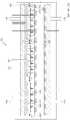
도 1은 본 발명의 실시 예에 따른 기판 처리 장치의 측면도.
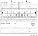
도 2는 본 발명의 실시 예에 따른 지지척의 측면도.
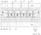
도 3은 본 발명의 변형 예에 따른 지지척의 부분도.
도 4 내지 도 8은 본 발명의 실시 예에 따른 기판 처리 장치의 작동 상태도.
도 9은 본 발명의 실시 예에 따른 기판 처리 방법의 순서도.1 is a side view of a substrate processing apparatus according to an embodiment of the present invention;
2 is a side view of a support chuck according to an embodiment of the present invention;
3 is a partial view of a support chuck according to a variant of the invention.
4 to 8 are operational states of a substrate processing apparatus according to an embodiment of the present invention.
9 is a flowchart of a substrate processing method according to an embodiment of the present invention.
이하, 첨부된 도면을 참조하여 본 발명의 실시 예를 상세히 설명한다. 그러나, 본 발명은 이하에서 개시되는 실시 예에 한정되는 것이 아니라 서로 다른 다양한 형태로 구현될 것이다. 단지 본 발명의 실시 예는 본 발명의 개시가 완전하도록 하고, 해당분야에서 통상의 지식을 가진 자에게 발명의 범주를 완전하게 알려주기 위해 제공되는 것이다. 도면은 실시 예를 설명하기 위해 그 크기가 과장될 수 있고, 도면상에서 동일 부호는 동일한 요소를 지칭한다.Hereinafter, embodiments of the present invention will be described in detail with reference to the accompanying drawings. However, the present invention is not limited to the embodiments described below, but may be embodied in various forms. It is to be understood that both the foregoing general description and the following detailed description of the present invention are exemplary and explanatory and are intended to provide further explanation of the invention as claimed. The drawings may be exaggerated in size to illustrate the embodiments, wherein like reference numerals refer to like elements throughout.
도 1은 본 발명의 실시 예에 따른 기판 처리 장치를 도시한 측면도이고, 도 2는 본 발명의 실시 예에 따른 지지척을 도시한 측면도이며, 도 3은 본 발명의 변형 예에 따른 지지척의 일 부분을 도시한 측면도이다. 또한, 도 4 내지 도 8은 본 발명의 실시 예에 따른 기판 처리 장치의 작동 상태를 도시한 모식도이고, 도 9는 본 발명의 실시 예에 따른 기판 처리 장치를 이용하여 기판을 처리하는 방법의 순서도이다.FIG. 1 is a side view showing a substrate processing apparatus according to an embodiment of the present invention, FIG. 2 is a side view showing a support chuck according to an embodiment of the present invention, and FIG. 3 is a cross- Fig. FIG. 9 is a flow chart of a method of processing a substrate using a substrate processing apparatus according to an embodiment of the present invention. FIG. to be.
본 발명의 실시 예에 따른 기판 처리 장치는 상부 기판과 하부 기판을 합착시키는 장치로서, 도 1 내지 도 8에 도시된 바와 같이, 기판 처리 공간을 가지는 챔버(100), 챔버(100) 내에 배치되어 상부 기판(S1)을 지지하는 상부 지지대(200), 상부 지지대(200)와 대향 배치되어 하부 기판(S2)를 지지하는 하부 지지대(300), 상부 지지대(200) 및 하부 지지대(300) 중 적어도 어느 하나의 지지대에 장착되며, 내부에 서로 분리되는 부분 공간(610: 610a, 610b)들을 가지는 지지척(600)을 포함한다. 여기서, 지지척(600)은 서로 고립된 부분 공간(610a, 610b)들에 선택적으로 주입되는 가스에 의하여 지지척(600)의 내측 또는 외측 방향으로 이동 가능한 점착부재(650)를 구비할 수 있고, 점착부재(650)를 이용하여 기판의 점착 고정 및 이탈 분리를 안정적으로 수행할 수 있다. 즉, 점착부재(650)는 기판의 고정 및 분리를 수행하는 동안 지지척(600)의 지지면에 형성된 후술하는 관통구(622) 내에서 움직이며, 관통구(622)내에 위치하거나, 지지척(600)의 지지면으로 노출될 수 있다. 상세하게는, 점착부재(650)는 부분 공간들 중 어느 하나 예컨대 상부 부분 공간(610a)에 가스가 주입되는 경우 지지척(600)의 외측으로 이동하여 지지척(600)에 지지되는 기판 예컨대 상부 기판(S1)에 점착되거나, 부분 공간들 중 나머지 예컨대 하부 부분 공간(610b)에 가스가 주입되는 경우 지지척(600)의 내측으로 이동하여 기판 예컨대 상부 기판(S1)으로부터 분리될 수 있다.1 to 8, a substrate processing apparatus according to an embodiment of the present invention includes a
한편, 본 발명의 실시 예에 따른 지지척(600)은 상부 지지대(200)에 장착되어 상부 기판(S1)을 점착 지지하나, 지지척(600)의 장착 위치는 특별히 한정되지 않는다. 예컨대 지지척(600)은 하부 지지대(200)에 장착되거나, 상부 지지대(200)와 하부 지지대(300)에 각각 장착될 수 있다.Meanwhile, the
상부 기판(S1)은 예컨대 OLED 소자가 형성된 소자 기판일 수 있고, 하부 기판(S2)은 예컨대 소자 기판을 캡핑하여 보호하는 캡핑 기판일 수 있으며, 상부 기판과 하부 기판의 베이스는 투과성 재질 예컨대 유리 패널일 수 있다. 물론 이에 한정되지 않고, 상부 기판과 하부 기판은 다양한 소자 및 장치를 구성하는 기판일 수 있으며, 예컨대 액정 표시 장치를 구성하는 액정 소자 기판일 수 있다.The upper substrate S1 may be, for example, an element substrate having an OLED element formed thereon, and the lower substrate S2 may be a capping substrate that protects, for example, an element substrate by capping. The base of the upper substrate and the lower substrate may be made of a transparent material, Lt; / RTI > Of course, the upper substrate and the lower substrate may be a substrate constituting various devices and devices, and may be, for example, a liquid crystal device substrate constituting a liquid crystal display device.
챔버(100)는 예컨대 상부 기판(S1)과 하부 기판(S2)의 합착 및 분리 공정을 수행하는 공간을 가지는 상부 챔버(100a)와 하부 챔버(100b)를 구비하며, 상부 챔버(100a)와 하부 챔버(100b)는 서로 착탈 가능하게 체결될 수 있다. 챔버(100)에는 상부 챔버(100a)와 하부 챔버(100b) 각각을 승하강 시킬 수 있는 별도의 승강부재(미도시)가 구비되며, 승강부재를 이용하여 상부 챔버(100a) 또는 하부 챔버(100b)를 승하강시킨 후, 상부 기판(S1)과 하부 기판(S2)을 챔버(100) 내로 반입하거나, 외부로 반출시킨다. 또한, 챔버(100)에는 내부의 압력을 조절하는 별도의 압력 조절 수단(미도시)과 불순물을 배기하는 별도의 배기 수단(미도시)이 구비된다.The
상부 지지대(200)는 챔버(100)의 내부 상측에 배치되어 상부 기판(S1)을 지지하는 역할을 한다. 상부 지지대(200)는 상부 기판(S1)의 형상에 대응하는 형상으로 제조될 수 있다. 예컨대, 상부 기판(S1)이 사각 판 형상의 유리 패널인 경우, 상부 지지대(200)는 사각 판 형상의 하부면을 구비하도록 제조될 수 있다.The
한편, 상부 지지대(200)의 하부면은 복수개의 영역으로 구분될 수 있고, 본 발명의 실시 예에 따른 지지척(600)은 복수개 구비되며, 상부 지지대(200)의 하부면에 형성되는 복수개의 영역별로 각각 장착될 수 있다. 물론, 이에 한정하지 않고, 지지척(600)은 하부 지지대(300)에도 장착될 수 있다. 상세하게는, 후술하는 하부 지지대(300)의 상부면에 형성되는 복수개의 영역별로 각각 장착될 수 있다.A plurality of support chucks 600 according to an embodiment of the present invention may be disposed on the lower surface of the
상부 구동부는 상부 지지대(200)에 연결되어 상부 지지대(200)를 승하강시킨다. 상부 구동부는 상부 지지대(200)와 연결된 상부 구동축(410)과 상부 구동축(410)에 동력을 인가하는 상부 동력부(미도시)를 구비한다. 상부 구동축(410)은 상부 챔버(100a)를 관통하여 상부 지지대(200)의 상부면에 장착되고, 상부 구동축(410)과 상부 챔버(100a)의 사이에는 별도의 밀봉부재(미도시)가 구비된다. 또한, 상부 구동부는 상부 지지대(200)를 X, Y 및 θ 방향으로 이동시켜 상부 지지대(200)의 위치를 정렬하는 별도의 정렬수단(미도시)과 상부 지지대(200)의 위치를 파악하는 별도의 센서(미도시) 예컨대 카메라를 더 구비할 수 있다.The upper driving part is connected to the upper supporting
하부 지지대(300)는 챔버(100)의 내측 하부에 배치되어 하부 기판(S2)을 지지하는 역할을 한다. 하부 지지대(300)는 하부 기판(S1)의 형상에 대응하는 형상으로 제조될 수 있고, 예컨대 사각 판 형상의 하부면을 구비하도록 제조될 수 있다.The
하부 구동부는 하부 지지대(300)에 연결되어 하부 지지대(300)를 승하강시킨다. 하부 구동부는 하부 지지대(300)와 연결된 하부 구동축(420)과 하부 구동축(420)에 동력을 인가하는 하부 동력부(미도시)를 구비한다. 하부 구동축(420)은 하부 챔버(100b)를 관통하여 하부 지지대(300)의 하부면에 장착되고, 하부 구동축(420)과 하부 챔버(100b)의 사이에는 별도의 밀봉부재(미도시)가 구비된다. 또한, 하부 구동부는 상부 구동부에 구비된 정렬수단 및 센서에 대응하는 별도의 정렬수단(미도시) 및 별도의 센서(미도시)를 더 구비할 수 있다.The lower driving part is connected to the lower supporting
하부 지지대(300)에 본 발명의 실시 예에 따른 지지척(600)이 장착되지 않는 경우에, 하부 지지대(300)에는 하부 기판(S2)를 고정하도록 흡착력부(미도시)가 구비될 수 있다. 흡착력부는 하부 지지대(300)의 상부면에 장착되며, 하부 기판(S2)를 고정할 수 있는 것을 만족하는 다양한 구성요소 및 구조를 가질 수 있고, 예컨대 진공척, 정전척 및 점착척을 포함할 수 있다.An attraction force unit (not shown) may be provided on the
리프트부재(500)는 상부 지지대(200)에 구비되어 상부 지지대(200)의 하부면에 상부 기판(S1)을 부착시키거나 분리시키는 것을 보조하고, 하부 지지대(300)에 구비되어 하부 지지대(300)의 상부면에 하부 기판(S2)을 부착시키거나 분리시키는 것을 보조한다. 이를 위해, 리프트부재(500) 예컨대 리프트핀은 상부 기판(S1)을 향하는 방향으로 상부 지지대(200)를 관통하여 상부 챔버(100a)에 장착될 수 있고, 하부 기판(S2)을 향하는 방향으로 하부 지지대(300)를 관통하여 하부 챔버(100b)에 장착될 수 있다. 이때, 상부 지지대(200)에 리프트부재(500)가 장착되는 경우, 리프트부재(500)는 상부 지지대(200)와 이에 장착된 지지척(600)을 관통하여 상부 챔버(100a)에 장착될 수 있다. 또한, 상부 지지대(200)에 장착되는 리프트부재(500)는 지지척(600)의 구성부들과 리프트부재(500)가 상호 간섭되지 않도록 그 장착위치가 선택될 수 있다. 또한, 상부 지지대(200)에 장착되는 리프트부재(500)와 지지척(600)의 사이에는 별도의 밀봉부재(미도시)가 구비될 수 있다. 상술한 리프트부재(500)의 장착 개수는 상부 기판(S1) 및 하부 기판(S2)의 크기에 대응되며, 리프트부재(500)는 서로 이격된 위치에서 복수개 장착될 수 있다. 또한, 리프트부재(500)는 이들을 승하강시키는 별도의 리프트부재 구동부(미도시)에 연결되어 상하 이동된다.The
리프트부재(500)들 중 상부 지지대(200)에 장착되는 리프트부재(이하, 상부 리프트부재)에는 별도의 진공척(미도시)가 구비될 수 있다. 상세하게는, 상부 리프트부재의 승하강 시 이에 접촉 지지되는 상부 기판(S1) 을 상부 리프트부재에 진공에 의하여 흡착 고정시키도록, 상부 기판(S1)을 향하는 리프트부재(500)의 단부에 별도의 진공척(미도시)이 구비될 수 있다. 여기서, 리프트부재(500)의 단부에 구비되는 별도의 진공척(미도시)은 기판과의 접촉 시 신축되어 그 접촉에 의한 충격을 소산시키고 기판의 손상이 방지되도록 벨로우즈(bellows) 타입의 진공 패드일 수 있다. 리프트부재(500)들 중 하부 지지대(300)에 장착되는 리프트부재(이하, 하부 리프트부재)에는 별도의 지지 패드(미도시)가 구비될 수 있다. 상세하게는, 하부 기판(S2)을 향하는 하부 리프트부재의 단부에는 소정 면적을 가지는 별도의 지지 패드(미도시)가 구비될 수 있고, 지지 패드에는 복수개의 하부 리프트부재가 연결될 수 있다. 하부 리프트부재는 지지 패드를 통하여 하부 기판(S)을 안정적으로 접촉 지지할 수 있다.
A separate vacuum chuck (not shown) may be provided on the lift member (hereinafter referred to as the upper lift member) mounted on the
이하, 본 발명의 실시 예에 따른 지지척(600)을 설명한다. 이때, 이하에서는 실시 예의 설명을 위하여 상부 기판(S1)과 하부 기판(S2)을 구분하여야 하는 경우를 제외하고, 상부 기판(S1)과 하부 기판(S2)을 특별히 구분하지 않아도 무방한 경우에는 이를 통틀어 기판이라 지칭한다.Hereinafter, a
본 발명의 실시 예에 따른 지지척(600)은 기판을 지지 및 고정시키도록 기판 처리 장치에 마련되는 구성부로서, 내부 공간과 기판을 지지하는 일면(621) 예컨대 지지면을 가지는 몸체(620), 몸체(620)의 내부 공간을 몸체(620)의 두께 방향으로 적층된 부분 공간(610: 610a, 610b)들로 분리시키며, 분리된 부분 공간(610)들에 선택적으로 주입되는 가스에 의하여 몸체(620)의 두께 방향으로 이동 가능하도록 몸체(620) 내에 장착되는 신축부재(630), 기판이 지지되는 몸체(620)의 일면(621) 예컨대 지지면을 몸체(620)의 두께 방향으로 관통하여 신축부재(630)에 장착되는 이동부재(640), 몸체(620)의 외측을 향하는 이동부재(640)의 단부에 장착되는 점착부재(650)를 포함한다.The supporting
몸체(620)는 상부 지지대(200)의 형상에 대응하는 형상 예컨대 육면체 형상으로 제작될 수 있다. 몸체(620)의 일면(621) 예컨대 하부면에 대향되는 타면 예컨대 상부면은 상부 지지대(200)의 하부면에 장착되고, 몸체(620)의 일면(621)에는 기판이 지지된다. 즉, 몸체(620)의 일면(621)은 기판을 지지하는 지지면의 역할을 한다. 몸체(620)의 상부면과 몸체(620)의 측면 각각의 일측에는 가스가 통과되는 배관(680)이 장착되며, 배관(680)을 통하여 몸체(620) 내로 가스를 주입하거나, 몸체(620) 내에 주입된 가스를 외부로 배출시킬 수 있다. 기판을 지지하는 몸체(620)의 일면(621) 예컨대 지지면에는 지지면을 관통하는 관통구(622)가 구비된다. 관통구(622)의 개수는 후술하는 이동부재(640)의 개수에 대응하며, 관통구(622)는 서로 이격되어 복수개 구비된다. 관통구(622) 내에는 후술하는 이동부재(640)의 일단 및 이에 장착되는 점착부재(650)가 위치하며, 점착부재(650)는 관통구(622)를 통하여 몸체(620)의 외부로 노출될 수 있다. 또한, 몸체(620)의 일면(621)에는 관통구(622)로부터 이격된 위치에 형성되는 복수개의 진공홀(623)이 구비될 수 있다. 상세하게는, 진공홀(623)은 몸체(620)의 일면(621)에 서로 이격되어 복수개 형성된다. 진공홀(623)에는 별도의 진공조절수단(미도시) 예컨대 진공펌프가 연결되고, 진공홀(623)은 진공조절수단에 의해 진공홀(623) 내의 진공이 조절되며 기판을 진공 흡착함으로써 지지척(600)의 지지면에 기판이 고정되는 것을 보조한다. 관통구(622)와 진공홀(623)은, 도 2에 도시된 바와 같이, 일정한 간격으로 서로 이격되어 형성될 수 있다.The body 620 may be formed in a shape corresponding to the shape of the
한편, 몸체(620)는 일체형으로 제작되거나, 분리형으로 제작될 수 있다. 본 실시 예에서는 분리형으로 제작되는 몸체(620)를 예시한다. 즉, 몸체(620)는 상부 몸체(620a)와 하부 몸체(620b)를 구비하며, 상부 몸체(620a)와 하부 몸체(620b)는 서로 착탈 가능하게 체결될 수 있다.On the other hand, the body 620 can be manufactured as an integral type or can be manufactured as a separate type. In this embodiment, a separate body 620 is illustrated. That is, the body 620 includes an
신축부재(630)는 이동부재(640) 및 이에 장착된 점착부재(650)를 구동시키도록 몸체(620) 내에 마련되는 구성부이다. 신축부재(630)는 몸체(620)의 내부 공간을 몸체(620)의 두께 방향으로 적층된 부분 공간(610)들로 분리시키도록 몸체(620) 내에 장착되는 탄성막(631)과 탄성막(631)의 일면에 장착되며, 탄성막(631)의 변형에 의하여 몸체(620)의 두께 방향으로 이동하는 보강판(632)을 구비할 수 있다.The
탄성막(631)은 탄성을 가지는 얇은 막 예컨대 다이어프램(diaphragm)일 수 있고, 그 재질은 예컨대 천연 고무, 합성 고무, 금속판 엔지니어링 플라스틱을 포함할 수 있다. 탄성막(631)은 예컨대 그 가장자리가 상부 몸체(620a)와 하부 몸체(620b)의 체결면 사이에서 몸체(620)에 장착될 수 있다. 이때, 탄성막(631)과 상부 몸체(620a) 및 하부 몸체(620b) 각각의 접촉면에는 별도의 밀봉수단(미도시)이 마련될 수 있다. 탄성막(631)에 의하여 몸체(620)의 내부 공간은 부분 공간 예컨대 상부 부분 공간(610a) 및 하부 부분 공간(610b)으로 분리될 수 있다. 상세하게는 탄성막(631)은 몸체(620) 내에 수평 방향으로 장착되어 몸체(620)의 내부 공간을 지지면에 평행한 방향으로 분할시킬 수 있다. 탄성막(631)은 탄성막(631)을 향해 분사되는 불활성 가스에 의해 팽창이 가능하고, 분사된 불활성 가스를 외부로 배기시키면 다시 수축하여 초기 위치로 복원될 수 있다. 즉, 분리된 부분 공간(610)들은 탄성막(631)에 의하여 서로 고립되어 연통되지 않는다. 이에, 상부 부분 공간(610a)에서 하부 부분 공간(610b)으로 가스가 유동하지 않으며, 또한, 그 반대의 경우에도 가스가 유동하지 않는다. 즉, 상부 부분 공간(610a)에 가스가 주입되는 경우 탄성막(631)이 하측으로 팽창될 수 있고, 하부 부분 공간(610b)에 가스가 주입되는 경우 탄성막(631)은 상측으로 팽창될 수 있다.The
한편, 후술하는 이동부재(640)가 신축부재(630)에 안정적으로 장착되어 지지되며, 탄성막(631)의 팽창 및 수축 방향이 탄성막(631)이 몸체(620)의 두께 방향으로 제어되도록, 탄성막(631)의 적어도 일면에는 보강판(632)이 장착된다. 즉, 보강판(632)은 탄성막(631)의 하부면 또는 상부면에 장착될 수 있고, 또는, 탄성막(631)의 상부면 및 하부면에 각각 장착될 수 있다. 탄성막(631)에 보강판(632)이 장착됨으로 인하여 신축부재(630)의 일부 즉 보강판(632)이 탄성막(631)의 팽창 및 수축 시 몸체(620)의 지지면과 평행을 유지하면서 이동될 수 있다. 이를 위해, 보강판(632)은 탄성막(631)의 팽창 또는 수축 시 보강판(632)이 탄성막(631)의 팽창 또는 수축되는 방향으로 굽힘 변형되지 않도록 소정의 강도를 가지며, 그 형상은 몸체(620)의 형상에 대응하는 형상 예컨대 사각판 형상으로 제작될 수 있다. 상술한 보강판(632)에 의하여 탄성막(631)은 그 변형 방향이 목적하는 방향 예컨대 몸체(620)의 두께 방향으로 제어될 수 있고, 후술하는 이동부재(640)들은 보강판(632)에 의하여 서로 몸체(620)의 두께 방향으로의 동일한 높이를 유지하며 몸체(620) 내에서 이동될 수 있다. 한편, 보강판(632)은 후술하는 이동부재(640)가 목적하는 개수만큼 장착되어 지지될 수 있는 것을 만족하도록 면적의 하한이 형성될 수 있다. 또한, 보강판(632)은 가장자리가 몸체(620)로부터 소정 간격 이격되도록 그 면적의 상한이 형성되며, 이에 탄성막(631)은 가스의 주입 및 배기에 의한 팽창과 수축을 수용할 수 있는 소정 면적을 가질 수 있다. 즉, 보강판(632)은 탄성막(631)의 전체 면적 중 보강판(632)의 가장자리와 몸체(620)와의 사이에 위치하는 탄성막(631)의 면적, 즉, 보강판(632)이 장착되지 않은 면적이 팽창 또는 수축함에 따라 몸체(620)의 두께 방향으로 이동할 수 있다.The
이동부재(640)는 하부 몸체(620b)의 일면(621) 예컨대 지지면을 몸체(620)의 두께 방향으로 관통하여 신축부재(630)에 장착되며, 이때, 보강판(632)에 의하여 안정적으로 지지된다. 이동부재(640)는 적어도 일부 상세하게는 몸체(620)의 외측을 향하는 이동부재(640)의 일단이 몸체(620)의 일면(621)에 형성된 관통구(622)에 삽입된다. 이동부재(640)는 개수는 기판의 크기에 대응하여 복수개 구비되며, 서로 이격되어 배치된다. 이동부재(640)는 신축부재(630)의 상측 즉, 상부 부분 공간(610a)에 위치하는 상부이동부재(640a)와 신축부재(630)의 하측 즉, 하부 부분 공간(610b)에 위치하는 하부이동부재(640b)로 구분될 수 있다. 하부이동부재(640b)의 형성길이는 몸체(620)의 일면(621)을 향하는 이동부재(640)의 일단이 몸체(620)의 관통구(622) 내에 위치하도록 그 길이가 형성될 수 있다. 상부이동부재(640a)의 형성길이는 이동부재(640)의 타단이 후술하는 샤워헤드(660)로부터 소정 간격 이격될 수 있도록 그 길이가 형성될 수 있다. 이때, 이동부재(640)의 타단과 후술하는 샤워헤드(660)의 이격 간격은 신축부재(630)가 상승 팽창하는 경우 그 변화를 수용하는 역할을 한다. 즉, 이동부재(640)의 타단과 후술하는 샤워헤드(660)의 이격 간격은 후술하는 점착부재(650)의 행정거리 예컨대 점착부재의 상한위치와 하한위치 사이의 거리를 의미한다. 상부이동부재(640a)는 이동부재(640)의 상승시 스토퍼의 역할을 한다. 한편, 이동부재(640)는 신축부재(630)에 장착되어 신축부재(630)의 이동에 대응하여 이동하여야 함에 따라 예컨대 다음과 같이 신축부재(630)에 결합될 수 있다. 하부 이동부재(640b)의 상단의 외주면에는 돌기(641)가 형성되고, 이에 대응하여 상부 이동부재(640a)의 상단의 외주면에는 와셔(washer)(642)가 마련된다. 돌기와 와셔는 신축부제(630)에 각각 접촉되고, 이를 관통하여 볼트(643)가 장착되어 이동부재(640)를 신축부재(630)에 장착시킨다. 이때, 와셔는 신축부재(630)에 이동부재(640)를 고정시키는 역할 및 이동부재(640)에 의해 관통된 신축부재(630)를 실링하는 역할을 할 수 있다.The
점착부재(650)는 점착력으로 기판을 고정하는 부재로서, 기판에 점착되었다가 떨어지더라도 기판에 점착 흔적을 남기지 않으면서, 이동부재(640)의 일단에 그대로 장착될 수 있는 특성을 가지는 재질로 제작될 수 있다. 예컨대, 점착부재(650)는 실리콘계 또는 아크릴계 또는 불소계 등으로 이루어진 점착 시트일 수 있다. 점착부재(650)는 관통구(622)를 통하여 이동가능하도록 이동부재(640)의 일단에 장착되고, 이에 몸체(620)의 관통구(622)를 통하여 몸체(620)의 외측으로 노출된다. 몸체(620)의 일면(621) 예컨대 지지면으로 노출되는 점착부재(650)의 점착면의 형상은 원형일 수 있다. 점착부재(650)는 이동부재(640)의 단부에 예컨대 볼트(bolt)(미도시)에 의해 결합되어 장착되거나, 접착재(binder)에 의해 접착되어 장착될 수 있다. 점착부재(650)는 이동부재(640)의 일단에 장착되어 몸체(620)의 관통구(622) 내에서 이동부재(640)의 승하강에 의해 이동된다. 상세하게는, 점착부재(650)의 점착면(651)은 부분 공간들에 선택적으로 주입되는 가스에 의하여, 몸체(620)의 관통구(622) 내에서 지지면과 나란하도록 위치하여 기판에 점착되거나, 관통구(622) 내에서 지지면으로부터 이격되도록 위치하여 기판과의 점착이 해제될 수 있다.The
한편, 본 발명의 실시 예에 따른 지지척(600)은 부분 공간(610)들 중 적어도 어느 하나에 몸체(620)의 두께 방향으로 가스를 주입하도록 몸체(620) 내에 장착되는 샤워헤드(660)를 더 포함할 수 있다. 상세하게는, 샤워헤드(660)는 상부 부분 공간(610a)에 몸체(620)의 두께 방향으로 가스를 주입하도록 상부 몸체(620a) 내에 장착되며, 상부 몸체(620a)의 일측에 장착된 상부 배관(681)에 연결된다. 샤워헤드(660)는 몸체(620)의 두께 방향으로 형성되는 복수개의 분사구(661)를 가지는 하부판 예컨대 다공판과 하부판의 상측에서 하부판의 가장자리를 둘러싸는 측벽을 구비할 수 있고, 측벽의 상부가 상부 몸체(620a)의 내측 상부에 기밀하게 장착된다. 샤워헤드(660)의 하부판은 상부 몸체(620a)의 내측 상부로부터 소정 거리 이격되어 배치되며, 하부판의 면적은 보강판(632)의 크기에 대응하도록 형성될 수 있다. 샤워헤드(660)에 의하여 상부 부분 공간(610a) 및 보강판(632)으로 균일하게 가스가 분사될 수 있고, 이에 신축부재(630)에 균일한 힘이 가해질 수 있으며, 신축부재(630)가 수평을 유지하며 승강 또는 하강될 수 있다. 물론 샤워헤드(660)은 하부 부분 공간(610b)에 가스를 주입하도록 하부 몸체(620b)에 장착될 수 있고, 각각의 몸체(620)에 모두 장착될 수 있다.The supporting
한편, 본 발명의 실시 예에 따른 지지척(600)은 신축부재(630)가 몸체(620) 내에서 몸체(620)의 두께 방향으로 동일한 높이를 유지하며 이동되도록, 부분 공간들 중 적어도 어느 하나의 위치에서 몸체(620) 내에 장착되며, 일단이 신축부재(630)에 연결되는 완충부재(670)을 더 포함할 수 있다. 즉, 완충부재(670)는 신축부재(630)를 향하는 방향으로 몸체(620) 내에 장착되며, 일부 구성부가 신축부재(630)에 접촉 연결됨으로써 신축부재(630)를 탄성 지지한다. 장착된 완충부재(670)에 의해 신축부재(630)는 신축부재(630)에 일차 편향적으로 분사되는 가스에 의한 압력을 견디며, 목적하는 속도로 완만하게 몸체(620)의 두께 방향으로 승하강할 수 있다. 이에 신축부재(630)의 갑작스러운 돌출 구동 및 신축부재(630)와 이동부재(640)의 스틱 슬립(stick slip)현상 즉, 진동 현상이 방지될 수 있다.The
본 발명의 실시 예에서는 신축부재(630)의 하측 즉, 하부 부분 공간(610b)에서 하부 몸체(620b)에 장착되는 완충부재(670)를 예시하나, 이에 한정하지 않고, 완충부재(670)는 신축부재(630)의 상측 즉, 상부 부분 공간(610a)에서 상부 몸체(620a)에 장착될 수 있다. 또한, 완충부재(670)는 신축부재(730)의 상측 및 하측 각각에서 상부 몸체(620a) 및 하부 몸체(620b)에 각각 장착되어 상부 부분 공간(610a) 및 하부 부분 공간(610b)에 각각 위치할 수 있다. 한편, 이하에서는 하부 몸체(620b)에 장착되는 완충부재(670)를 중심으로 완충부재(670)의 기술적 특징들을 설명하나, 이는 완중부재(670)가 상부 몸체(620a)에 장착되더라도 동일하게 적용될 수 있다.A cushioning
완충부재(670)는 신축부재(630)를 향하는 방향으로 몸체(620) 내에 장착되는 가이드부재(671)와 가이드부재(671)의 외측에 마련되며, 일단이 몸체(620)에 연결 지지되고, 타단이 신축부재(630)에 연결 지지되는 탄성부재(672)를 포함할 수 있다. 이때, 가이드부재(671)는 신축부재(630)를 마주보는 가이드부재(671)의 일단이 신축부재(630)로부터 이격되도록 길이가 형성된다. 상세하게는 가이드부재(671)의 일단이 가이드부재(671)를 향하는 방향으로 신축부재(630)가 이동하는 경우에 신축부재(630)에 접촉하고, 그 외의 경우에 신축부재(630)로부터 이격되도록 가이드부재(671)의 길이가 형성된다. 탄성부재(672) 예컨대 탄성 스프링은 양 단부가 신축부재(630)와 몸체(620)에 장착 고정 되거나 접촉 연결되며, 탄성력에 의해 이들을 지지한다. 상술한 완충부재(670)는 복수개 구비되어 하부 몸체(620b)의 복수의 위치에 장착되며, 이때, 복수개의 완충부재(670)는 수평 방향으로 서로 동일 간격 이격되어 위치할 수 있고, 이에 신축부재(630)가 몸체(620)의 두께 방향으로 이동할 때 보강판(632)이 하부 몸체(620b)의 일면(621) 예컨대 지지면과 평행하도록 이를 탄성 지지할 수 있다.The
배관(680)은 상부 배관(681)과 하부 배관(682)를 포함하며, 상부 배관(681)은 상부 몸체(620a)의 상부면 또는 측면 중 어느 한 면에 장착되고, 하부 배관(682)은 하부 몸체(620b)의 측면에 장착될 수 있다. 각각의 배관(680)은 챔버(100)의 외측으로 연장되어 챔버(100)의 외부에 마련된 가스공급조절수단(미도시)에 연결된다. 이때 각각의 배관(680)과 챔버(100)의 사이에는 별도의 밀봉수단(미도시)이 마련될 수 있다. 여기서 밀봉수단은 예컨대 고무 패킹, 가스킷 및 씰링 씰 등을 포함하는 밀봉에 적합한 다양한 밀봉수단일 수 있다. 가스공급조절수단(미도시)은 몸체(620)의 내부 공간에 가스를 주입 및 배기시키는 역할을 하며, 이때, 상부 부분 공간(610a)에 가스를 주입시키는 경우 하부 부분 공간(610b)로부터 가스를 배기시키며, 하부 부분 공간(610b)에 가스를 주입시키는 경우 상부 부분 공간(610a)로부터 가스를 배기시킬 수 있다. 즉, 상부 부분 공간(610a)과 하부 부분 공간(610b)에 선택적으로 가스를 주입 배기시키며, 가스의 주입과 배기는 서로 교차 수행된다. 이를 위해 가스공급조절수단(미도시)은 복수개 구비되어 상부 배관(681)과 하부 배관(682)에 각각 연결될 수 있다. 또한, 가스공급조절수단은 예컨대 소정 압력으로 가스를 주입가능한 가스공급원(미도시)과 주입된 가스를 배기시키는 배기펌프(미도시)를 구비할 수 있고, 가스저장부와 배기펌프와 배관(680)의 사이에는 각각 가스의 이동을 제어하는 제어밸브(미도시)가 장착될 수 있다.The piping 680 includes an
한편, 도 3에 도시된 바와 같이, 본 발명의 변형 예에 따른 지지척(600)은 점착부재(650)의 외주면 또는 이동부재(640)의 일단의 외주면과 몸체(620)의 관통구(622)의 내벽 사이를 실링하도록 관통구(622)의 일단에 장착되는 실링부재(690: 691, 692, 693)를 더 포함할 수 있다. 이를 위해 관통구(622)의 일단은 관통구(622)의 나머지 영역 또는 중심 영역보다 큰 내경을 가지도록 형성될 수 있고, 이에 실링부재(690)가 장착될 수 있는 공간이 마련될 수 있다. 예컨대 실링부재는 점착부재(650)의 외주면으로부터 관통구(622)의 일단의 내벽을 향하여 연장 형성되는 실링막(691)과 실링막(691)을 관통구(622)의 일단에 기밀하게 장착시키도록 관통구(622)의 일단의 내벽에 장착되는 링부재(692)를 포함할 수 있다. 실링막(691)은 예컨대 탄성막(631)과 동일한 재질로 제작될 수 있고, 점착부재(650)의 외주면에 형성되는 막일 수 있으며, 점착부재(650)와 별도로 구비되는 막일 수 있다. 점착부재(650)와 별도로 구비되는 막일 경우에 실링막은 점착부재(650)의 외주면 또는 이동부재(640) 일단의 외주면에 예컨대 접착재에 의해 접착되어 기밀하게 장착될 수 있다. 링부재(692)는 실링막(691)을 관통구(622)의 내벽에 장착시키도록 마련되는 구성부이며, 점착부재(650)의 이동 시 실링막(691)을 지지하며, 실링막과 관통구(622)의 일단의 밀봉상태를 유지시키는 역할을 한다. 링부재(692)는 관통구(622) 일단에 예컨대 볼트(693)에 의해 결합되어 장착되거나, 접착재에 의해 접착되어 장착될 수 있다, 또한, 실링부재(690)는 몸체(620)의 외측을 향하는 방향의 관통구(622)의 일단에 장착되어 몸체(620) 외부로 노출될 수 있고, 몸체(620)의 내측을 향하는 방향의 관통구(622)의 타단이 관통구(622)의 중심보다 큰 내경을 가지도록 형성되고, 관통구(622)의 타단에 실링부재(690)가 장착되어 몸체(620) 내부에 위치할 수 있다.
3, the supporting
도 9는 본 발명의 실시 예에 따른 기판 처리 방법의 순서도이다. 이하에서는 도 1 내지 도 9을 참조하여 본 발명의 실시 예에 따른 기판 처리 방법을 설명한다. 이때, 본 발명의 실시 예에 따른 기판 처리 장치의 설명과 중복되는 설명은 생략하거나 간단히 설명하기로 한다.9 is a flowchart of a substrate processing method according to an embodiment of the present invention. Hereinafter, a substrate processing method according to an embodiment of the present invention will be described with reference to FIGS. 1 to 9. FIG. At this time, the description of the substrate processing apparatus according to the embodiment of the present invention and the duplicate description will be omitted or briefly described.
기판 처리 방법은 상술한 기판 처리 장치를 이용하여 기판의 합착을 수행하는 방법으로서, 상부 기판(S1) 및 하부 기판(S2)을 마련하는 과정, 하부 기판(S2)을 하부 지지대(300)에 지지시키고, 상부 기판(S1)을 상부 지지대(200)에 지지시키는 과정, 상부 지지대(200)의 지지척(600)을 이용하여 상부 기판(S1)을 지지척(600)에 고정시키는 과정, 상부 지지대(200)와 하부 지지대(300)의 간격을 좁혀 상부 기판(S1)과 하부 기판(S2)을 밀착시키는 과정, 상부 기판(S1)과 지지척(600)의 고정을 해제하는 과정, 상부 지지대(200) 및 하부 지지대(300)로부터 합착된 기판을 분리하는 과정을 포함한다. 여기서, 상부 기판(S1)을 지지척(600)에 고정시키는 과정은, 지지척(600) 내의 상부 부분 공간에 가스를 주입하는 과정과, 지지척의 점착부재를 하강시키는 과정과, 상부 기판에 점착부재를 점착시키는 과정을 포함한다. 또한, 상부 기판(S2)과 지지척의 고정을 해제하는 과정은, 지지척 내의 하부 부분 공간에 가스를 주입하는 과정과, 지지척의 점착부재를 상승시키는 과정과, 상부기판으로부터 점착부재를 분리시키는 과정을 포함한다.The substrate processing method is a method of performing cohesion of a substrate using the above-described substrate processing apparatus. The method includes the steps of providing an upper substrate S1 and a lower substrate S2, A process of fixing the upper substrate S1 to the supporting
먼저, 기판을 준비한다(S100). 예컨대 로봇 암(미도시)을 이용하여 상부 기판(S1)을 상부 지지대(200)의 하측에 위치시키고, 하부 기판(S2)을 하부 지지대(300)의 상측에 위치시킨다. 이때, 하부 기판의 상부면에는 하부 기판의 가장자리를 따라서 접합부재(미도시) 예컨대 실란트(sealant)가 마련될 수 있다.First, a substrate is prepared (S100). The upper substrate S1 is positioned below the upper support table 200 and the lower substrate S2 is positioned above the lower support table 300 by using a robot arm (not shown). At this time, a joining member (not shown) such as a sealant may be provided on the upper surface of the lower substrate along the edge of the lower substrate.
이후, 도 4 및 도 5에 도시된 바와 같이, 하부 기판(S2)을 하부 지지대(300)의 상부면에 안착 지지시키고(S210), 상부 기판(S1)을 상부 지지대(200)의 지지척(600)에 진공 흡착 방식으로 지지시킨다(S220). 상부 기판(S1)을 상부 지지대(200)의 지지척(600)에 흡착 지지시키는 과정은, 예컨대 리프트부재(500)를 하강시켜 상부 기판(S1)에 접촉시키고, 진공 흡착 방식으로 리프트부재(500)에 상부 기판(S1)을 지지시킨 상태에서, 리프트부재(500)를 상승시켜 상부 기판(S1)의 상부면과 지지척(600)의 지지면을 접촉시킨다. 이어서, 지지면의 진공홀(623)에 진공을 형성하여 상부 기판(S1)을 지지면에 흡착 지지 시킨다.4 and 5, the lower substrate S2 is supported on the upper surface of the lower supporter 300 (S210), and the upper substrate S1 is supported on the
다음으로, 지지척(600)의 상부 부분 공간(610a)과 연결된 가스공급원(미도시)의 제어밸브(미도시)를 개방하여 가스공급원으로부터 지지척(600)의 상부 부분 공간(610a)으로 불활성 가스 예컨대 질소 가스를 주입시킨다(S310). 이때, 샤워헤드(660)에 의하여 가스는 상부 부분공간(610a)내에 균일하게 분사될 수 있다. 가스의 주입에 의하여 탄성막(631)은 팽창하며, 샤워헤드(660) 및 보강판(632)에 의하여 팽창 방향이 몸체(620)의 두께 방향으로 제어된다. 신축부재(630)의 하강에 의하여 이에 장착된 이동부재(640) 및 점착부재(650)가 하강된다(S320). 이때, 완충부재(670)가 신축부재(630)의 이동방향으로 수축되며 신축부재(630)에 소정의 탄성력을 가하고, 탄성력에 의해 신축부재(630)는 안정적으로 이동될 수 있다. 신축부재(630)가 완충부재(670)의 가이드부재(671)에 접촉되면 신축부재(630)의 이동이 중지된다. 즉, 가이드부재(671)은 스토퍼의 역할을 수행한다. 이와 같은 과정을 수행하여 점착부재(650)의 점착면은 기판을 향하여 가압 및 이동되어 기판의 상부면에 가압 밀착되고, 이에 점착면(651)을 통하여 점착부재(650)와 기판이 점착 고정된다(S330).Next, a control valve (not shown) of a gas supply source (not shown) connected to the upper
여기서, 상부 부분 공간(610a)에 불활성 가스가 공급되기 전 즉, 신축부재(630)의 초기 위치에서의 점착부재(650)의 점착면의 위치는 하부 몸체(620b)의 지지면과 나란하게 위치되거나, 또는 상기의 지지면에서 기판을 향하는 방향으로 소정 간격 돌출되어 위치될 수 있다. 점착부재(650)의 위치는 초기 상태에서의 신축부재(630)를 탄성력으로 지지하도록 완충부재(670)에 구비되는 탄성부재(672)의 길이를 조절함으로써 목적하는 위치로 용이하게 선택할 수 있다.Here, the position of the adhesive surface of the
기판이 점착 고정되면, 상부 부분 공간(610a)에 연결된 제어 밸브를 잠가 상부 부분 공간(610a)으로의 가스 주입을 차단한다. 이때, 상부 부분 공간(610a)에 주입된 가스를 유지시키거나 또는, 상부 배관(681)을 통하여 상부 부분 공간(610a)으로부터 가스를 배기할 수 있다. 가스를 배기하는 경우 신축부재(630)가 완충부재(670)에 의하여 초기 위치로 복귀되며 점착부재(650)의 점착면이 기판을 가압하는 동작이 중지되고, 점착면은 초기 위치로 복귀한다. 한편, 기판의 점착 고정 과정에서 점착부재(650)의 가압에 의해 기판의 소정 영역이 변형될 수 있으나, 점착부재(650)의 점착면이 기판을 가압하는 동작이 중지됨에 따라 기판의 변형이 해제되어 원래 형태로 복귀될 수 있다.When the substrate is adhered and fixed, the control valve connected to the upper
이어서, 기판과 점착부재(650)의 점착 고정이 완료되면, 챔버(100)를 밀폐시키고, 기판을 각 지지대에 마련하는 과정 즉, 기판의 로딩 과정에서 대기압(atm) 분위기로 형성되었던 챔버(100)의 내부 분위기를 진공 분위기로 형성한다. 이때, 지지척(600)의 진공홀(623)에 형성되었던 진공이 파괴되며 진공홀(623)과 상부 기판(S1)과의 진공 흡착이 해제되나, 상부 기판(S1)은 점착부재(650)에 점착 지지됨에 의하여 그 고정상태가 유지될 수 있다. 즉, 점착부재(650)와 상부 기판(S1)과의 점착 고정이 완료되면, 챔버(100)의 내부 분위기 제어에 의해 지지척(600)의 진공홀(623)의 진공상태가 파괴되어도 점착부재(650)의 점착력에 의하여 상부 기판(S1)이 고정 지지될 수 있다.After the adhesion of the substrate and the
이후, 상부 기판(S1)과 하부 기판(S2)를 정렬시킨다(S400). 그리고, 챔버(100) 내부를 진공 상태로 유지시킨다.Subsequently, the upper substrate S1 and the lower substrate S2 are aligned (S400). Then, the inside of the
이어서, 상부 지지대(200) 및 하부 지지대(300) 중 적어도 하나를 이용하여 상부 기판과 하부 기판의 간격을 좁힌다. 예컨대 도 5에 도시된 바와 같이, 하부 지지대(300)를 상승시켜 상부 기판과 하부 기판을 밀착시킨다(S500). 물론, 이와 동시에 상부 지지대(200)를 하강시켜 이들을 밀착시킬 수 있다.Next, at least one of the
밀착이 완료되면, 도 7에 도시된 바와 같이, 지지척(600)의 하부 부분 공간(610a)과 연결된 가스공급원(미도시)의 제어밸브(미도시)를 개방하여 가스공급원으로부터 지지척(600)의 하부 부분 공간(610b)으로 불활성 가스 예컨대 질소 가스를 주입시킨다(S610). 이때, 지지척(600) 내의 상부 부분 공간(610a)에 기 주입된 가스를 상부 배관(681)을 통하여 배기시킨다. 이러한 과정에서 하부 부분 공간에 주입되는 가스의 주입 속도 및 압력과 상부 부분 공간에 주입되는 가스의 주입 속도 및 압력을 목적하는 비율로 조정함으로써, 신축부재(630)의 상승을 원활하게 수행할 수 있다. 가스의 주입에 의하여 하측으로 팽창된 탄성막(631)은 초기 위치로 수축된 뒤 경우에 따라 상측을 향하여 팽창될 수 있다. 상세하게는, 이동부재(640)의 상단부가 샤워헤드(660)에 접촉될 때까지 보강판(632)을 상승시키도록 탄성막(631)이 샤워헤드(660)를 향하는 방향으로 더 팽창될 수 있다. 물론, 이때에도 보강판(632)에 의하여 탄성막(631)의 팽창 방향이 몸체(620)의 두께 방향으로 제어된다. 신축부재(630)의 상승에 의하여 이에 장착된 이동부재(640) 및 점착부재(650)가 하강된다(S620). 이때, 완충부재(670)가 신축부재(630)의 이동방향으로 탄성복원되며 신축부재(630)에 소정의 탄성력을 가하고, 탄성력에 의해 신축부재(630)는 안정적으로 이동될 수 있다. 이동부재(640)의 상단이 샤워헤드(660)에 접촉되면 신축부재(630)의 이동이 중지된다. 즉, 이동부재(640)의 상단 예컨대 상부이동부재(640a)는 스토퍼의 역할을 수행한다. 이와 같은 과정을 수행하여 점착부재(650)의 점착면은 기판으로부터 멀어지는 방향으로 이동, 상부 기판(S1)의 상부면으로부터 점착이 해제되고, 이에 점착부재(650)와 상부 기판(S1)이 분리된다(S330). 지지척(600)으로부터 분리된 상부 기판(S1)은 하부 기판(S2) 상에 안착 지지된다. 점착부재(650)와 상부 기판(S1)과의 점착이 해제되면, 하부 부분 공간(610a)에 연결된 제어 밸브를 잠가 가스의 주입을 중단한다. 이어서, 하부 배관(682)을 통하여 이에 공급된 가스를 배기할 수 있다. 이로 인해 점착부재(650)가 초기 위치로 복귀할 수 있다.7, a control valve (not shown) of a gas supply source (not shown) connected to the
상술한 바와 같이 점착부재(650)를 지지척(600)의 내측 방향으로 이동시키며, 점착부재(650)와 상부 기판(S1)의 점착을 해제시키는 동안, 지지척(600)의 지지면과 상부 기판(S1)의 접촉 지지 상태가 유지되므로, 종래보다 기판의 분리를 안정적으로 수행할 수 있으면, 정렬된 기판의 틀어짐을 방지할 수 있다.While the
한편, 본 발명의 실시 예에서는 관통구(622)의 일단에 실링부재(690)가 마련될 수 있고, 마련되지 않을 수 있으며, 실링부재(690)가 마련되지 않는 경우 하부 부분 공간(610b)로 주입되는 가스 중 적어도 일부는 관통구(622)와 점착부재(650)의 사이로 분사될 수 있다. 이에, 하부 부분 공간(610b)으로 주입되는 가스는 상부 기판(S1)과 지지척(600)을 분리하는 동안 상부 기판(S1)과 지지척(600)의 분리를 돕는 퍼지(purge)가스의 역할을 할 수 있다.Meanwhile, in the embodiment of the present invention, the sealing member 690 may be provided at one end of the through
다음으로, 도 8에 도시된 바와 같이, 상부 지지대를 상승시킨다(S700). 이때, 상부 지지대(200)를 상승시키는 동안 또는 상승 전후에 지지척(600)의 하부 부분 공간(610b)에 주입된 가스를 배기하여 주입 가스에 의해 지지척(600) 내부 구성부들에 각각 작용하는 압력을 해제하고, 그 상태를 초기상태로 전환시킬 수 있다.Next, as shown in FIG. 8, the upper support is raised (S700). At this time, the gas injected into the
이후, 하부 지지대(300)에 마련된 리프트부재(500)를 상승시켜 하부 지지대(300)로부터 기판을 분리시킨 후, 이를 별도의 경화장치(미도시)로 이동시킨다. 그리고, 경화장치를 이용하여 접합부재 예컨대 실런트에 광 예컨대 자외선(UV)를 조사하여, 이를 경화시켜 기판의 합착을 완료한다(S800).
Thereafter, the
본 발명은 기판을 합착시키는 공정 및 장치의 경우가 예시되었으니, 이외의 다양한 기판 처리 공정 및 이를 수행하는 장치에도 적용될 수 있다. 한편 본 발명의 상기 실시 예는 그 설명을 위한 것이며, 그 제한을 위한 것이 아님을 주지해야 한다. 또한, 본 발명이 해당하는 기술분야에서의 업자는 본 발명의 기술 사상의 범위 내에서 다양한 실시 예가 가능함을 이해할 수 있을 것이다.
The present invention can be applied to various substrate processing processes other than the process and device for attaching the substrates together. It should be noted, however, that the above-described embodiment of the present invention is for the purpose of explanation and not for the purpose of limitation. It is to be understood that various modifications may be made by those skilled in the art without departing from the scope of the present invention.
100: 챔버200: 상부 지지대
500: 리프트부재600: 지지척
610a: 상부 부분 공간610b: 하부 부분 공간
620: 몸체630: 신축부재
650: 점착부재660: 샤워헤드100: chamber 200: upper support
500: lift member 600: support chuck
610a:
620: body 630: elastic member
650: Adhesive member 660: Shower head
Claims (16)
Translated fromKorean내부 공간을 가지는 몸체;
상기 내부 공간을 상기 몸체의 두께 방향으로 분리시키며 분리된 부분 공간들에 주입되는 가스에 의하여 상기 몸체의 두께 방향으로 이동가능하도록 상기 몸체 내에 장착되는 신축부재;
상기 몸체의 일면을 상기 몸체의 두께 방향으로 관통하여 상기 신축부재에 장착되는 복수개의 이동부재;
상기 몸체의 외측을 향하는 상기 이동부재의 단부에 장착되는 점착부재; 및
상기 부분 공간들 중 적어도 어느 하나에 상기 몸체의 두께 방향으로 가스를 주입하도록 상기 몸체 내에 장착되는 샤워헤드;를 포함하고,
상기 신축부재는 이동부재들이 지지되는 보강판을 구비하고,
상기 샤워헤드는 상기 신축부재가 상기 기판과 평행을 유지하며 승하강하도록 상기 보강판의 크기에 대응하는 면적으로 형성되는 하부판을 구비하고,
상기 신축부재에 의하여 상기 이동부재들이 서로 동일한 높이를 유지하며 상기 몸체의 두께방향으로 이동하는 지지척.
1. A support chuck for supporting a substrate,
A body having an inner space;
A stretchable member mounted on the body so as to be able to move in the thickness direction of the body by the gas injected into the separated partial spaces while separating the internal space in the thickness direction of the body;
A plurality of moving members that penetrate one side of the body in a thickness direction of the body and are mounted on the elastic members;
An adhesive member mounted on an end of the moving member facing the outside of the body; And
And a showerhead mounted in the body to inject gas into at least one of the partial spaces in a thickness direction of the body,
Wherein the elastic member comprises a reinforcing plate on which the moving members are supported,
Wherein the showerhead has a bottom plate formed to have an area corresponding to a size of the reinforcing plate so that the stretching and shrinking member is parallel to the substrate,
Wherein the movable members are moved in the thickness direction of the body while maintaining the same height by the elastic members.
상기 부분 공간들 중 적어도 어느 하나에 장착되며, 일단이 상기 신축부재에 연결되는 완충부재;를 포함하는 지지척.
The method according to claim 1,
And a buffer member mounted on at least one of the partial spaces and having one end connected to the elastic member.
상기 몸체의 일면에는 관통구 및 진공홀이 구비되며,
상기 점착부재는 상기 관통구 내에 위치하는 지지척.
The method according to claim 1,
A through hole and a vacuum hole are formed on one surface of the body,
And the adhesive member is located in the through-hole.
상기 몸체의 외측으로 노출되는 상기 점착부재의 점착면은 상기 부분 공간들에 선택적으로 주입되는 가스에 의하여 상기 관통구 내에 위치하거나, 상기 몸체의 일면과 나란하도록 위치하는 지지척.
The method of claim 4,
Wherein the adhesive surface of the adhesive member exposed to the outside of the body is positioned in the through hole by a gas selectively injected into the partial spaces or positioned so as to be parallel to one surface of the body.
상기 점착부재 및 상기 이동부재의 상기 단부 중 적어도 하나와 상기 관통구의 사이를 실링하도록 상기 관통구에 장착되는 실링부재;를 포함하는 지지척.
The method of claim 4,
And a sealing member mounted on the through-hole so as to seal between the adhesive member and at least one of the end portions of the moving member and the through-hole.
상기 신축부재는,
상기 내부 공간을 분리시키도록 상기 몸체 내에 장착되는 탄성막;을 포함하고,
상기 보강판은 상기 탄성막의 변형에 의하여 상기 몸체의 두께 방향으로 이동가능하도록 상기 탄성막의 적어도 일면에 장착되는 지지척.
The method according to claim 1,
The elastic member
And an elastic membrane mounted in the body to separate the internal space,
Wherein the reinforcing plate is mounted on at least one surface of the elastic film so as to be movable in the thickness direction of the body by deformation of the elastic film.
상기 완충부재는,
상기 신축부재를 향하는 방향으로 상기 몸체 내에 장착되는 가이드부재;
상기 가이드부재의 외측에 마련되며, 일단이 상기 신축부재에 연결되고, 타단이 상기 몸체에 연결되는 탄성부재;를 포함하는 지지척.
The method of claim 3,
The cushioning member,
A guide member mounted in the body in a direction toward the elastic member;
And an elastic member provided on the outer side of the guide member and having one end connected to the elastic member and the other end connected to the body.
상기 챔버 내에 배치되는 상부 지지대;
상기 상부 지지대와 대향 배치되는 하부 지지대; 및
상기 상부 지지대 및 상기 하부 지지대 중 적어도 어느 하나의 지지대에 장착되며, 내부에 서로 분리되는 부분 공간들을 가지는 지지척;을 포함하고,
상기 지지척은,
내부 공간을 가지는 몸체;
상기 내부 공간을 상기 몸체의 두께 방향으로 분리시키며 분리된 부분 공간들에 주입되는 가스에 의하여 상기 몸체의 두께 방향으로 이동가능하도록 상기 몸체 내에 장착되는 신축부재;
상기 신축부재에 장착되고, 적어도 일단이 상기 몸체의 외면에 삽입되는 복수개의 이동부재;
상기 몸체의 외측을 향하는 상기 이동부재의 단부에 결합되고, 상기 부분 공간들에 선택적으로 주입되는 가스에 의하여 상기 지지척의 외측 또는 내측 방향으로 이동 가능한 점착부재; 및
상기 부분 공간들 중 적어도 어느 하나에 상기 몸체의 두께 방향으로 가스를 주입하도록 상기 몸체 내에 장착되는 샤워헤드;를 구비하고,
상기 신축부재는 이동부재들이 지지되는 보강판을 구비하고,
상기 샤워헤드는 상기 신축부재가 상기 기판과 평행을 유지하며 승하강하도록 상기 보강판의 크기에 대응하는 면적으로 형성되는 하부판을 구비하고,
상기 신축부재에 의하여 상기 이동부재들이 서로 동일한 높이를 유지하며 상기 몸체의 두께방향으로 이동하는 기판 처리 장치.
A chamber having a substrate processing space;
An upper support disposed within the chamber;
A lower support disposed to face the upper support; And
And a support chuck mounted on a support of at least one of the upper support and the lower support, the support chuck having partial spaces separated from each other,
Wherein the support chuck comprises:
A body having an inner space;
A stretchable member mounted on the body so as to be able to move in the thickness direction of the body by the gas injected into the separated partial spaces while separating the internal space in the thickness direction of the body;
A plurality of moving members mounted on the elastic members and having at least one end inserted into the outer surface of the body;
An adhesive member coupled to an end of the movable member facing the outside of the body and movable in an outer side or an inner side of the support chuck by a gas selectively injected into the partial spaces; And
And a showerhead mounted in the body to inject gas into at least one of the partial spaces in a thickness direction of the body,
Wherein the elastic member comprises a reinforcing plate on which the moving members are supported,
Wherein the showerhead has a bottom plate formed to have an area corresponding to a size of the reinforcing plate so that the stretching and shrinking member is parallel to the substrate,
Wherein the movable members are kept at the same height by the elastic members and move in the thickness direction of the body.
상기 지지척은 복수개 구비되며, 상기 상부 지지대의 하부면 및 상기 하부 지지대의 상부면 중 적어도 어느 하나에 형성되는 복수개의 영역별로 각각 장착되는 기판 처리 장치.
The method of claim 9,
Wherein the plurality of support chucks are mounted on each of a plurality of regions formed on at least one of a lower surface of the upper support and an upper surface of the lower support.
상기 지지척은 상기 신축부재를 향하는 방향으로 상기 몸체 내에 장착되어 상기 신축부재를 접촉 지지하는 완충부재, 상기 부분 공간들에 각기 가스를 주입하는 배관을 구비하는 기판 처리 장치.
The method of claim 9,
Wherein the support chuck includes a buffer member mounted in the body in a direction toward the elastic member to contact and support the elastic member, and a pipe for injecting gas into the partial spaces.
상기 몸체의 일면에는 관통구 및 진공홀이 구비되고,
상기 점착부재는 상기 관통구를 통하여 이동가능하도록 상기 몸체의 외측을 향하는 상기 이동부재의 단부에 결합되는 기판 처리 장치.
The method of claim 9,
A through hole and a vacuum hole are formed on one surface of the body,
And the adhesive member is coupled to an end of the moving member which is directed to the outside of the body so as to be movable through the through-hole.
상기 신축부재는 상기 내부 공간을 상기 몸체의 두께 방향으로 분리시키도록 상기 몸체 내에 장착되는 탄성막을 구비하고,
상기 보강판은 상기 탄성막의 적어도 일면에 장착되는 기판 처리 장치.
The method of claim 9,
Wherein the elastic member has an elastic membrane mounted in the body to separate the inner space in the thickness direction of the body,
Wherein the reinforcing plate is mounted on at least one surface of the elastic film.
상기 완충부재는 상기 부분 공간들 중 적어도 어느 하나에 상기 신축부재를 향하는 방향으로 장착되며, 상기 신축부재를 향하는 일단이 상기 신축부재로부터 이격되는 가이드부재, 상기 가이드부재의 외측에 마련되며, 일단이 상기 몸체에 연결 지지되고, 타단이 상기 신축부재에 연결 지지되는 탄성부재를 구비하는 기판 처리 장치.
The method of claim 12,
Wherein the cushioning member is mounted on at least one of the partial spaces in a direction facing the elastic member and has one end facing the elastic member and spaced apart from the elastic member, And an elastic member connected to the body and having an opposite end connected to the elastic member.
상기 관통구와 상기 점착부재의 외주면의 사이를 실링하도록 상기 관통구의 일단에는 실링부재가 장착되는 기판 처리 장치.
14. The method of claim 13,
And a sealing member is mounted at one end of the through hole so as to seal between the through hole and the outer peripheral surface of the adhesive member.
Priority Applications (4)
| Application Number | Priority Date | Filing Date | Title |
|---|---|---|---|
| KR1020140084578AKR101838681B1 (en) | 2014-07-07 | 2014-07-07 | Support chuck and apparatus for treating substrate |
| JP2015134981AJP6634231B2 (en) | 2014-07-07 | 2015-07-06 | Support chuck and substrate processing device |
| TW104121974ATWI662651B (en) | 2014-07-07 | 2015-07-07 | Support chuck and substrate treating apparatus |
| CN201510395072.5ACN105244306A (en) | 2014-07-07 | 2015-07-07 | Support chuck and apparatus for treating substrate |
Applications Claiming Priority (1)
| Application Number | Priority Date | Filing Date | Title |
|---|---|---|---|
| KR1020140084578AKR101838681B1 (en) | 2014-07-07 | 2014-07-07 | Support chuck and apparatus for treating substrate |
Publications (2)
| Publication Number | Publication Date |
|---|---|
| KR20160005538A KR20160005538A (en) | 2016-01-15 |
| KR101838681B1true KR101838681B1 (en) | 2018-03-14 |
Family
ID=55041894
Family Applications (1)
| Application Number | Title | Priority Date | Filing Date |
|---|---|---|---|
| KR1020140084578AExpired - Fee RelatedKR101838681B1 (en) | 2014-07-07 | 2014-07-07 | Support chuck and apparatus for treating substrate |
Country Status (4)
| Country | Link |
|---|---|
| JP (1) | JP6634231B2 (en) |
| KR (1) | KR101838681B1 (en) |
| CN (1) | CN105244306A (en) |
| TW (1) | TWI662651B (en) |
Families Citing this family (6)
| Publication number | Priority date | Publication date | Assignee | Title |
|---|---|---|---|---|
| KR102336572B1 (en)* | 2015-01-23 | 2021-12-08 | 삼성디스플레이 주식회사 | Substrate desorption apparatus and method for manufacturing display device using threrof |
| KR102674847B1 (en)* | 2016-12-08 | 2024-06-12 | 엘지디스플레이 주식회사 | Apparatus and Method of processing a substrate and Method of manufacturing Display Device using the same |
| KR101884853B1 (en)* | 2016-12-30 | 2018-08-02 | 세메스 주식회사 | Substrate support unit and apparatus to treat substrate including same |
| KR102211815B1 (en) | 2018-04-09 | 2021-02-04 | 정회욱 | A method of constructing a closure member for an indoor wall and thereof indoor wall closure system |
| JP7163944B2 (en)* | 2020-09-15 | 2022-11-01 | 日新イオン機器株式会社 | Substrate holder and ion implanter |
| CN118471860B (en)* | 2024-06-10 | 2024-12-31 | 山东汉芯科技有限公司 | Chip bonding device |
Citations (2)
| Publication number | Priority date | Publication date | Assignee | Title |
|---|---|---|---|---|
| KR100850238B1 (en)* | 2007-09-03 | 2008-08-04 | 주식회사 에이디피엔지니어링 | Substrate Chuck and Substrate Bonding Device |
| JP2013257594A (en)* | 2013-08-30 | 2013-12-26 | Hitachi Ltd | Liquid crystal substrate lamination system |
Family Cites Families (10)
| Publication number | Priority date | Publication date | Assignee | Title |
|---|---|---|---|---|
| US6080050A (en)* | 1997-12-31 | 2000-06-27 | Applied Materials, Inc. | Carrier head including a flexible membrane and a compliant backing member for a chemical mechanical polishing apparatus |
| KR100895468B1 (en)* | 2004-10-28 | 2009-05-06 | 신에츠 엔지니어링 가부시키가이샤 | Adhesive chuck device |
| JP4379435B2 (en)* | 2006-05-17 | 2009-12-09 | 株式会社日立プラントテクノロジー | Board assembly apparatus and board assembly method using the same |
| WO2008093408A1 (en)* | 2007-01-31 | 2008-08-07 | Shin-Etsu Engineering Co., Ltd. | Adhesive chuck device |
| US20090056866A1 (en)* | 2007-09-03 | 2009-03-05 | Jae Seok Hwang | Substrate bonding apparatus and method |
| KR100894739B1 (en)* | 2007-11-02 | 2009-04-24 | 주식회사 에이디피엔지니어링 | Board Bonding Device |
| US8245751B2 (en)* | 2007-11-07 | 2012-08-21 | Advanced Display Process Engineering Co., Ltd. | Substrate bonding apparatus |
| KR101340614B1 (en) | 2011-12-30 | 2013-12-11 | 엘아이지에이디피 주식회사 | Substrate bonding apparatus |
| JP2013187393A (en)* | 2012-03-08 | 2013-09-19 | Tokyo Electron Ltd | Bonding device and bonding method |
| CN104919189B (en)* | 2012-12-25 | 2017-04-12 | 信越工程株式会社 | Actuator and adhesive chuck device |
- 2014
- 2014-07-07KRKR1020140084578Apatent/KR101838681B1/ennot_activeExpired - Fee Related
- 2015
- 2015-07-06JPJP2015134981Apatent/JP6634231B2/ennot_activeExpired - Fee Related
- 2015-07-07TWTW104121974Apatent/TWI662651B/ennot_activeIP Right Cessation
- 2015-07-07CNCN201510395072.5Apatent/CN105244306A/enactivePending
Patent Citations (3)
| Publication number | Priority date | Publication date | Assignee | Title |
|---|---|---|---|---|
| KR100850238B1 (en)* | 2007-09-03 | 2008-08-04 | 주식회사 에이디피엔지니어링 | Substrate Chuck and Substrate Bonding Device |
| JP2013257594A (en)* | 2013-08-30 | 2013-12-26 | Hitachi Ltd | Liquid crystal substrate lamination system |
| JP5642239B2 (en) | 2013-08-30 | 2014-12-17 | 株式会社日立製作所 | LCD substrate bonding system |
Also Published As
| Publication number | Publication date |
|---|---|
| CN105244306A (en) | 2016-01-13 |
| JP2016018996A (en) | 2016-02-01 |
| KR20160005538A (en) | 2016-01-15 |
| TWI662651B (en) | 2019-06-11 |
| JP6634231B2 (en) | 2020-01-22 |
| TW201603182A (en) | 2016-01-16 |
Similar Documents
| Publication | Publication Date | Title |
|---|---|---|
| KR101838681B1 (en) | Support chuck and apparatus for treating substrate | |
| KR100855461B1 (en) | Adhesion Chuck and Substrate Bonding Device | |
| KR100352919B1 (en) | Apparatus and method for manufacturing liquid crystal display | |
| KR100850238B1 (en) | Substrate Chuck and Substrate Bonding Device | |
| KR20100085366A (en) | Substrate holder unit and subtrate assembling appartus having the same | |
| KR20210092225A (en) | Micro device transfer device and manufacturing method thereof | |
| KR101292802B1 (en) | apparatus for attaching substrates of flat plate display element | |
| KR101494757B1 (en) | Substrate holder module and apparatus for treatmenting substrate having the same | |
| KR100994499B1 (en) | Apparatus for assembling substrates and Method for assembling substrates | |
| KR101261491B1 (en) | Substrate bonding apparatus and substrate bonding method | |
| KR101471002B1 (en) | Apparatus and method for treating substrate | |
| KR100913220B1 (en) | Board Bonding Device | |
| KR100894739B1 (en) | Board Bonding Device | |
| KR20120087462A (en) | Substrate bonding apparatus and substrate bonding method | |
| KR20130054307A (en) | Substrate bonding apparatus and substrate bonding method | |
| KR101288864B1 (en) | Substrate bonding apparatus | |
| KR101340614B1 (en) | Substrate bonding apparatus | |
| KR101268397B1 (en) | Substrate bonding apparatus and substrate bonding method | |
| KR101299284B1 (en) | Substrate bonding apparatus and substrate bonding method | |
| KR101261489B1 (en) | Substrate bonding apparatus | |
| KR101401506B1 (en) | apparatus for attaching substrates of flat plate display element | |
| KR100921997B1 (en) | Board Bonding Device | |
| KR100486943B1 (en) | Apparatus for holding of flat panel | |
| KR20110103693A (en) | Substrate chuck and substrate processing apparatus using the same | |
| KR101232905B1 (en) | Substrate bonding apparatus and substrate bonding method |
Legal Events
| Date | Code | Title | Description |
|---|---|---|---|
| PA0109 | Patent application | St.27 status event code:A-0-1-A10-A12-nap-PA0109 | |
| PG1501 | Laying open of application | St.27 status event code:A-1-1-Q10-Q12-nap-PG1501 | |
| A201 | Request for examination | ||
| PA0201 | Request for examination | St.27 status event code:A-1-2-D10-D11-exm-PA0201 | |
| P22-X000 | Classification modified | St.27 status event code:A-2-2-P10-P22-nap-X000 | |
| PE0902 | Notice of grounds for rejection | St.27 status event code:A-1-2-D10-D21-exm-PE0902 | |
| PN2301 | Change of applicant | St.27 status event code:A-3-3-R10-R13-asn-PN2301 St.27 status event code:A-3-3-R10-R11-asn-PN2301 | |
| PN2301 | Change of applicant | St.27 status event code:A-3-3-R10-R11-asn-PN2301 | |
| R19-X000 | Request for party data change rejected | St.27 status event code:A-3-3-R10-R19-oth-X000 | |
| PN2301 | Change of applicant | St.27 status event code:A-3-3-R10-R11-asn-PN2301 | |
| R19-X000 | Request for party data change rejected | St.27 status event code:A-3-3-R10-R19-oth-X000 | |
| N231 | Notification of change of applicant | ||
| PN2301 | Change of applicant | St.27 status event code:A-3-3-R10-R13-asn-PN2301 St.27 status event code:A-3-3-R10-R11-asn-PN2301 | |
| E13-X000 | Pre-grant limitation requested | St.27 status event code:A-2-3-E10-E13-lim-X000 | |
| P11-X000 | Amendment of application requested | St.27 status event code:A-2-2-P10-P11-nap-X000 | |
| P13-X000 | Application amended | St.27 status event code:A-2-2-P10-P13-nap-X000 | |
| E90F | Notification of reason for final refusal | ||
| PE0902 | Notice of grounds for rejection | St.27 status event code:A-1-2-D10-D21-exm-PE0902 | |
| P11-X000 | Amendment of application requested | St.27 status event code:A-2-2-P10-P11-nap-X000 | |
| P13-X000 | Application amended | St.27 status event code:A-2-2-P10-P13-nap-X000 | |
| E701 | Decision to grant or registration of patent right | ||
| PE0701 | Decision of registration | St.27 status event code:A-1-2-D10-D22-exm-PE0701 | |
| GRNT | Written decision to grant | ||
| PR0701 | Registration of establishment | St.27 status event code:A-2-4-F10-F11-exm-PR0701 | |
| PR1002 | Payment of registration fee | St.27 status event code:A-2-2-U10-U11-oth-PR1002 Fee payment year number:1 | |
| PG1601 | Publication of registration | St.27 status event code:A-4-4-Q10-Q13-nap-PG1601 | |
| PC1903 | Unpaid annual fee | St.27 status event code:A-4-4-U10-U13-oth-PC1903 Not in force date:20210309 Payment event data comment text:Termination Category : DEFAULT_OF_REGISTRATION_FEE | |
| PC1903 | Unpaid annual fee | St.27 status event code:N-4-6-H10-H13-oth-PC1903 Ip right cessation event data comment text:Termination Category : DEFAULT_OF_REGISTRATION_FEE Not in force date:20210309 | |
| R18-X000 | Changes to party contact information recorded | St.27 status event code:A-5-5-R10-R18-oth-X000 |