KR101837502B1 - Ferromagnetic amorphous alloy ribbon reduced surface defects and application thereof - Google Patents
Ferromagnetic amorphous alloy ribbon reduced surface defects and application thereofDownload PDFInfo
- Publication number
- KR101837502B1 KR101837502B1KR1020137006078AKR20137006078AKR101837502B1KR 101837502 B1KR101837502 B1KR 101837502B1KR 1020137006078 AKR1020137006078 AKR 1020137006078AKR 20137006078 AKR20137006078 AKR 20137006078AKR 101837502 B1KR101837502 B1KR 101837502B1
- Authority
- KR
- South Korea
- Prior art keywords
- ribbon
- alloy
- less
- content
- defect
- Prior art date
- Legal status (The legal status is an assumption and is not a legal conclusion. Google has not performed a legal analysis and makes no representation as to the accuracy of the status listed.)
- Active
Links
- 229910000808amorphous metal alloyInorganic materials0.000titleclaimsabstractdescription33
- 230000005294ferromagnetic effectEffects0.000titleclaimsabstractdescription18
- 230000007547defectEffects0.000titleclaimsdescription67
- 229910045601alloyInorganic materials0.000claimsabstractdescription105
- 239000000956alloySubstances0.000claimsabstractdescription105
- 230000005291magnetic effectEffects0.000claimsabstractdescription75
- 230000006698inductionEffects0.000claimsdescription43
- 238000005266castingMethods0.000claimsdescription30
- 238000000034methodMethods0.000claimsdescription23
- 230000005284excitationEffects0.000claimsdescription17
- 239000000203mixtureSubstances0.000claimsdescription17
- 239000011573trace mineralSubstances0.000claimsdescription10
- 235000013619trace mineralNutrition0.000claimsdescription10
- 239000000126substanceSubstances0.000claimsdescription9
- QVGXLLKOCUKJST-UHFFFAOYSA-Natomic oxygenChemical compound[O]QVGXLLKOCUKJST-UHFFFAOYSA-N0.000claimsdescription8
- 238000004519manufacturing processMethods0.000claimsdescription8
- 229910052759nickelInorganic materials0.000claimsdescription8
- 239000001301oxygenSubstances0.000claimsdescription8
- 229910052760oxygenInorganic materials0.000claimsdescription8
- 229910052804chromiumInorganic materials0.000claimsdescription6
- 229910052802copperInorganic materials0.000claimsdescription6
- 229910052748manganeseInorganic materials0.000claimsdescription6
- 239000012535impuritySubstances0.000claimsdescription5
- 239000002184metalSubstances0.000claimsdescription4
- 229910052751metalInorganic materials0.000claimsdescription4
- 230000007613environmental effectEffects0.000claimsdescription3
- 239000011162core materialSubstances0.000description48
- XEEYBQQBJWHFJM-UHFFFAOYSA-NIronChemical compound[Fe]XEEYBQQBJWHFJM-UHFFFAOYSA-N0.000description40
- 229910052799carbonInorganic materials0.000description7
- 229910021417amorphous siliconInorganic materials0.000description5
- 230000008018meltingEffects0.000description5
- 238000002844meltingMethods0.000description5
- 229910052710siliconInorganic materials0.000description5
- 238000000137annealingMethods0.000description4
- 229910052742ironInorganic materials0.000description4
- 230000005496eutecticsEffects0.000description3
- 239000007789gasSubstances0.000description3
- MYMOFIZGZYHOMD-UHFFFAOYSA-NDioxygenChemical compoundO=OMYMOFIZGZYHOMD-UHFFFAOYSA-N0.000description2
- 229910008423Si—BInorganic materials0.000description2
- 238000009749continuous castingMethods0.000description2
- 238000010586diagramMethods0.000description2
- 229910001882dioxygenInorganic materials0.000description2
- 230000000694effectsEffects0.000description2
- 239000003302ferromagnetic materialSubstances0.000description2
- 230000007774longtermEffects0.000description2
- 239000000696magnetic materialSubstances0.000description2
- 239000000463materialSubstances0.000description2
- 239000002994raw materialSubstances0.000description2
- 229910052717sulfurInorganic materials0.000description2
- 229910052718tinInorganic materials0.000description2
- 229910052721tungstenInorganic materials0.000description2
- 238000004804windingMethods0.000description2
- 229910017082Fe-SiInorganic materials0.000description1
- 229910000519FerrosiliconInorganic materials0.000description1
- 229910017133Fe—SiInorganic materials0.000description1
- 229910001128Sn alloyInorganic materials0.000description1
- 229910000831SteelInorganic materials0.000description1
- 230000015572biosynthetic processEffects0.000description1
- 239000011248coating agentSubstances0.000description1
- 238000000576coating methodMethods0.000description1
- 229910021419crystalline siliconInorganic materials0.000description1
- 230000007423decreaseEffects0.000description1
- 230000003247decreasing effectEffects0.000description1
- 230000002349favourable effectEffects0.000description1
- 229910052735hafniumInorganic materials0.000description1
- 230000003760hair shineEffects0.000description1
- 229910052739hydrogenInorganic materials0.000description1
- 238000011835investigationMethods0.000description1
- XWHPIFXRKKHEKR-UHFFFAOYSA-Niron siliconChemical compound[Si].[Fe]XWHPIFXRKKHEKR-UHFFFAOYSA-N0.000description1
- 239000007791liquid phaseSubstances0.000description1
- 230000005415magnetizationEffects0.000description1
- 229910052750molybdenumInorganic materials0.000description1
- 229910052758niobiumInorganic materials0.000description1
- 238000010587phase diagramMethods0.000description1
- 229910052698phosphorusInorganic materials0.000description1
- 238000005498polishingMethods0.000description1
- 239000002244precipitateSubstances0.000description1
- 238000001556precipitationMethods0.000description1
- 238000002360preparation methodMethods0.000description1
- 239000010453quartzSubstances0.000description1
- VYPSYNLAJGMNEJ-UHFFFAOYSA-Nsilicon dioxideInorganic materialsO=[Si]=OVYPSYNLAJGMNEJ-UHFFFAOYSA-N0.000description1
- 239000010959steelSubstances0.000description1
- 229910052726zirconiumInorganic materials0.000description1
Images


Classifications
- H—ELECTRICITY
- H01—ELECTRIC ELEMENTS
- H01F—MAGNETS; INDUCTANCES; TRANSFORMERS; SELECTION OF MATERIALS FOR THEIR MAGNETIC PROPERTIES
- H01F1/00—Magnets or magnetic bodies characterised by the magnetic materials therefor; Selection of materials for their magnetic properties
- H01F1/01—Magnets or magnetic bodies characterised by the magnetic materials therefor; Selection of materials for their magnetic properties of inorganic materials
- H01F1/03—Magnets or magnetic bodies characterised by the magnetic materials therefor; Selection of materials for their magnetic properties of inorganic materials characterised by their coercivity
- H01F1/12—Magnets or magnetic bodies characterised by the magnetic materials therefor; Selection of materials for their magnetic properties of inorganic materials characterised by their coercivity of soft-magnetic materials
- H01F1/14—Magnets or magnetic bodies characterised by the magnetic materials therefor; Selection of materials for their magnetic properties of inorganic materials characterised by their coercivity of soft-magnetic materials metals or alloys
- H01F1/147—Alloys characterised by their composition
- H01F1/153—Amorphous metallic alloys, e.g. glassy metals
- B—PERFORMING OPERATIONS; TRANSPORTING
- B22—CASTING; POWDER METALLURGY
- B22D—CASTING OF METALS; CASTING OF OTHER SUBSTANCES BY THE SAME PROCESSES OR DEVICES
- B22D11/00—Continuous casting of metals, i.e. casting in indefinite lengths
- B22D11/06—Continuous casting of metals, i.e. casting in indefinite lengths into moulds with travelling walls, e.g. with rolls, plates, belts, caterpillars
- B22D11/0611—Continuous casting of metals, i.e. casting in indefinite lengths into moulds with travelling walls, e.g. with rolls, plates, belts, caterpillars formed by a single casting wheel, e.g. for casting amorphous metal strips or wires
- H—ELECTRICITY
- H01—ELECTRIC ELEMENTS
- H01F—MAGNETS; INDUCTANCES; TRANSFORMERS; SELECTION OF MATERIALS FOR THEIR MAGNETIC PROPERTIES
- H01F1/00—Magnets or magnetic bodies characterised by the magnetic materials therefor; Selection of materials for their magnetic properties
- H01F1/01—Magnets or magnetic bodies characterised by the magnetic materials therefor; Selection of materials for their magnetic properties of inorganic materials
- H01F1/03—Magnets or magnetic bodies characterised by the magnetic materials therefor; Selection of materials for their magnetic properties of inorganic materials characterised by their coercivity
- H01F1/12—Magnets or magnetic bodies characterised by the magnetic materials therefor; Selection of materials for their magnetic properties of inorganic materials characterised by their coercivity of soft-magnetic materials
- H01F1/14—Magnets or magnetic bodies characterised by the magnetic materials therefor; Selection of materials for their magnetic properties of inorganic materials characterised by their coercivity of soft-magnetic materials metals or alloys
- H01F1/147—Alloys characterised by their composition
- H01F1/153—Amorphous metallic alloys, e.g. glassy metals
- H01F1/15308—Amorphous metallic alloys, e.g. glassy metals based on Fe/Ni
- H—ELECTRICITY
- H01—ELECTRIC ELEMENTS
- H01F—MAGNETS; INDUCTANCES; TRANSFORMERS; SELECTION OF MATERIALS FOR THEIR MAGNETIC PROPERTIES
- H01F27/00—Details of transformers or inductances, in general
- H01F27/24—Magnetic cores
- H01F27/25—Magnetic cores made from strips or ribbons
- H—ELECTRICITY
- H01—ELECTRIC ELEMENTS
- H01F—MAGNETS; INDUCTANCES; TRANSFORMERS; SELECTION OF MATERIALS FOR THEIR MAGNETIC PROPERTIES
- H01F41/00—Apparatus or processes specially adapted for manufacturing or assembling magnets, inductances or transformers; Apparatus or processes specially adapted for manufacturing materials characterised by their magnetic properties
- H01F41/02—Apparatus or processes specially adapted for manufacturing or assembling magnets, inductances or transformers; Apparatus or processes specially adapted for manufacturing materials characterised by their magnetic properties for manufacturing cores, coils, or magnets
- H01F41/0206—Manufacturing of magnetic cores by mechanical means
- H01F41/0213—Manufacturing of magnetic circuits made from strip(s) or ribbon(s)
- H01F41/0226—Manufacturing of magnetic circuits made from strip(s) or ribbon(s) from amorphous ribbons
- H—ELECTRICITY
- H01—ELECTRIC ELEMENTS
- H01F—MAGNETS; INDUCTANCES; TRANSFORMERS; SELECTION OF MATERIALS FOR THEIR MAGNETIC PROPERTIES
- H01F1/00—Magnets or magnetic bodies characterised by the magnetic materials therefor; Selection of materials for their magnetic properties
- H01F1/01—Magnets or magnetic bodies characterised by the magnetic materials therefor; Selection of materials for their magnetic properties of inorganic materials
- H01F1/03—Magnets or magnetic bodies characterised by the magnetic materials therefor; Selection of materials for their magnetic properties of inorganic materials characterised by their coercivity
- H01F1/12—Magnets or magnetic bodies characterised by the magnetic materials therefor; Selection of materials for their magnetic properties of inorganic materials characterised by their coercivity of soft-magnetic materials
- H01F1/14—Magnets or magnetic bodies characterised by the magnetic materials therefor; Selection of materials for their magnetic properties of inorganic materials characterised by their coercivity of soft-magnetic materials metals or alloys
- H01F1/147—Alloys characterised by their composition
- H01F1/153—Amorphous metallic alloys, e.g. glassy metals
- H01F1/15333—Amorphous metallic alloys, e.g. glassy metals containing nanocrystallites, e.g. obtained by annealing
Landscapes
- Engineering & Computer Science (AREA)
- Power Engineering (AREA)
- Physics & Mathematics (AREA)
- Electromagnetism (AREA)
- Chemical & Material Sciences (AREA)
- Dispersion Chemistry (AREA)
- Manufacturing & Machinery (AREA)
- Mechanical Engineering (AREA)
- Soft Magnetic Materials (AREA)
- Continuous Casting (AREA)
Abstract
Translated fromKoreanDescription
Translated fromKorean본 발명은 트랜스포머 코어(transformer cores), 회전용 기계(rotational machines), 전기식 쵸크(electrical chokes), 자기 센서(magnetic sensor) 및 펄스 파워 장치(pulse power devices)에 사용되는 강자성 비정질 합금 리본 및 상기 리본의 제조방법에 관한 것이다.
The present invention relates to a ferromagnetic amorphous alloy ribbon for use in transformer cores, rotational machines, electrical chokes, magnetic sensors and pulse power devices, And a method for producing the same.
철-계 비정질 합금 리본은 AC 여기(excitation)하에서의 낮은 자성 손실을 포함하는 뛰어난 연자성(soft magnetic property)을 나타내며, 이는 에너지 효율 자기 장치, 예를 들어, 트랜스포머, 모터, 발전기, 펄스 파워 발전기 및 자기 센서를 포함하는 에너지 관리 장치(energy management devices)에 적용될 수 있다. 이들 장치에서 높은 포화 자기유도(high saturation inductions) 및 높은 열 안정성을 갖는 강자성 물질이 바람직하다. 나아가, 상기 물질의 용이한 제조 및 이의 원료 물질의 비용은 각각 대규모 산업적 용도에서 중요한 요소이다. 비정질 Fe-B-Si계 합금은 이들 요구사항을 만족한다. 그러나, 이들 비정질 합금의 포화 자기유도(saturation inductions)는 트랜스포머와 같은 장치에 통상적으로 사용되는 결정질 실리콘 강(crystalline silicon steels)의 것보다 낮으며, 그 결과 다소 큰 크기의 비정질 합금-계 장치가 된다. 따라서, 더 높은 포화 자기유도를 갖는 비정질 강자성 합금을 개발하기 위해 노력하여 왔다. 한가지 방법은 Fe-계 비정질 합금에서 철 함량을 증가시키는 것이다. 그러나, Fe 함량의 증가에 따라, 합금의 열 안정성이 강등되므로 이는 간단하지 않다. 이 문제를 완화하기 위해, Sn, S, C 및 P 같은 원소가 첨가되었다. 예를 들어, 미국 특허 제 5,456,770호 ('770 특허)는 비정질 Fe-Si-B-C-Sn 합금을 교시하고 있으며, 여기서 Sn의 첨가는 합금의 성형성(formability) 및 이들의 포화 자기유도를 증가시킨다. 미국 특허 제 6,416,879호 ('879 특허)에서는, 비정질 Fe-Si-B-C-P 시스템에 P를 첨가함으로써 Fe함량을 증가시킴과 함께 포화 자기유도를 증가시키는 것으로 교시하고 있다. 그러나, Fe-Si-B-계 비정질 합금에 Sn, S 및 C와 같은 원소의 첨가는 캐스트 리본의 연성(ductility)을 감소시키며, 이는 와이드 리본(wide ribbon)의 제작을 어렵게 한다. 또한, '879 특허에서 가르치고 있는 바와 같이, Fe-Si-B-C 계 합금에 대한 P의 첨가는 장기간에 걸친 열 안정성 손실의 결과를 초래하며, 이는 수년 내에 수십 퍼센트의 자성 코어 손실의 증가를 초래한다. 따라서, '770 및 '879 특허에서 가르치고 있는 비정질 합금은 이의 용융 상태로부터 캐스팅함으로써 실질적으로 제조되지 않는다.
Iron-based amorphous alloy ribbons exhibit excellent soft magnetic properties including low magnetic loss under AC excitation, which can be used in energy efficient magnetic devices, such as transformers, motors, generators, pulsed power generators, And can be applied to energy management devices including magnetic sensors. In these devices, a ferromagnetic material with high saturation inductions and high thermal stability is desirable. Furthermore, the ease of preparation of these materials and the cost of their raw materials are important factors in large industrial applications, respectively. Amorphous Fe-B-Si based alloys meet these requirements. However, the saturation inductions of these amorphous alloys are lower than those of crystalline silicon steels commonly used in devices such as transformers, resulting in somewhat larger amorphous alloy-based devices . Thus, efforts have been made to develop amorphous ferromagnetic alloys with higher saturation magnetic induction. One method is to increase the iron content in Fe-based amorphous alloys. However, as the Fe content increases, the thermal stability of the alloy is degraded, which is not simple. To alleviate this problem, elements such as Sn, S, C and P were added. For example, U.S. Patent No. 5,456,770 (the '770 patent) teaches amorphous Fe-Si-BC-Sn alloys wherein the addition of Sn increases the alloy formability and saturation magnetic induction thereof . U.S. Patent No. 6,416,879 (the '879 patent) teaches that adding P to an amorphous Fe-Si-BCP system increases the Fe content and increases saturation magnetic induction. However, the addition of elements such as Sn, S and C to the Fe-Si-B-based amorphous alloy reduces the ductility of the cast ribbon, which makes it difficult to produce a wide ribbon. Also, as taught in the '879 patent, the addition of P to Fe-Si-BC based alloys results in long term thermal stability loss, which results in an increase in magnetic core losses of tens of percent in the years . Thus, the amorphous alloys taught in the '770 and' 879 patents are not substantially manufactured by casting from their molten state.
트랜스포머, 인덕터 등과 같은 자기 장치에 필요한 고 포화 자기유도뿐만 아니라, 높은 B-H 방형비(squareness ratio) 및 낮은 보자성(coercivity), Hc이 바람직하며, B 및 H는 각각 자기 유도(magnetic induction) 및 자기장 여기에 기여한다. 이 이유는 이러한 자성 재료가 용이한 자화(magnetization)를 의미하는 높은 자성 연성(magnetic softness)을 갖기 때문이다. 이는 이들 자성 재료를 이용한 자기 장치에서 자기 손실을 적게 한다. 이들 요소를 인식함으로써, 본 발명자들은 높은 리본-연성(ribbon-ductility)뿐만 아니라 이들 요구되는 자기적 특성이 미국 특허 제 7,425,239호에 기술되어 있는 바와 같이, 비정질 Fe-Si-B-C 시스템에서 Si:C의 비율을 특정한 수준으로 선택함으로써, 리본 표면상의 C 석출물층(precipitation layer)을 특정한 두께로 유지함으로써 달성됨을 발견하였다. 나아가, 일본 특허공개 제 2009052064호에서, 고 포화 자기유도 비정질 합금 리본이 제공되며, 여기서는 합금 시스템에 Cr 및 Mn을 첨가하여 C 석출물 층 높이를 제어함으로써 150℃의 장치 작동에서 150년까지의 향상된 열 안정성을 나타낸다. 그러나, 제작된 리본은 다수의 표면 결함, 예를 들어, 리본의 길이방향을 따라 그리고 캐스팅 칠 바디 표면(casting chill body surface)에 접촉하는 리본 표면의 맞은편인 캐스팅 분위기-면(casting atmosphere-side)을 향하는 리본 표면에 형성된, 스플리트 라인(split lines), 스크래치, 및 페이스 라인(face line)과 같은 다수의 표면 결함을 나타내었다. 스플리트 라인 및 페이스 라인의 예를 도 1에 나타내었다. 캐스팅 노즐의 기본적인 배열, 회전 휠(rotating wheel) 상의 칠 바디 표면(chill body surface) 및 결과물인 캐스트 리본(cast ribbon)은 미국 특허 제 4,142,571호에 기술되어 있다.
High BH squareness ratio, low coercivity, and Hc are desirable as well as high saturation magnetic induction required for magnetic devices such as transformers, inductors, etc., and B and H are magnetic induction and magnetic fields, respectively, It contributes here. This is because these magnetic materials have high magnetic softness which means easy magnetization. This reduces magnetic loss in magnetic devices using these magnetic materials. By recognizing these elements, the present inventors have found that not only high ribbon-ductility but also their required magnetic properties can be improved in Si: C (C) in an amorphous Fe-Si-BC system, as described in U.S. Patent No. 7,425,239 By maintaining the C precipitation layer on the ribbon surface at a particular thickness, by selecting the ratio of the thickness of the ribbon to a specific level. Further, in Japanese Patent Laid-Open No. 2009052064, a high saturation magnetic induction amorphous alloy ribbon is provided, wherein by controlling the height of the C precipitate layer by adding Cr and Mn to the alloy system, Stability. However, the fabricated ribbons are subject to a number of surface defects, for example, a casting atmosphere-side, which is opposite the ribbon surface in contact with the longitudinal direction of the ribbon and in contact with the casting chill body surface Such as split lines, scratches, and face lines, formed on the surface of the ribbon facing the surface of the ribbon. An example of a spline line and a face line is shown in Fig. The basic arrangement of the casting nozzle, the chill body surface on the rotating wheel, and the resulting cast ribbon are described in U.S. Patent No. 4,142,571.
따라서, 높은 수준의 리본 제작성(fabricability)과 함께, 높은 포화 자기유도, 낮은 자성 손실, 높은 B-H 방형비, 높은 기계적 연성(mechanical ductility), 높은 장기간의 열 안정성, 및 리본 표면 결함 감소를 나타내는 강자성 비정질 합금 리본이 필요하며, 이는 본 발명의 제 1 견지이다. 보다 특히, 캐스팅 도중 캐스트 리본 표면의 품질을 철저히 연구하여 다음을 알아내었다: 표면 결함은 캐스팅의 초기 단계에서 시작되며, 리본의 길이 방향을 따라, 결함 길이가 약 200 mm를 초과하거나 혹은 결함 깊이가 리본 두께의 약 40%를 초과하는 경우에, 리본은 결함 위치에서 파손되며, 그 결과 갑작스럽게 캐스팅이 종결된다. 이 리본 파손으로 인하여, 캐스팅이 시작 후, 30분 내의 캐스팅 종결 비율이 약 20%에 이른다. 반면에, 1.6 T 미만의 포화 자기 유도를 갖는 리본에 대하여, 30분 이내의 캐스트 종결 비율은 약 3%였다. 또한, 이들 리본에서, 리본의 길이방향을 따라 1.5m 마다 1 혹은 2개의 결함 발생 정도로, 결함길이는 200mm 미만이었으며, 결함 깊이는 리본 두께의 40% 미만이었다. 따라서, 포화 자기 유도가 1.6T를 초과하는 리본에서 표면 결함의 감소는 연속 캐스팅을 달성하기 위해 명백하게 요구되며, 이는 본 발명의 다른 견지이다. 본 발명의 주요한 견지는 트랜스포머(transformer), 회전용 기계(rotational machines), 전기식 쵸크(electrical chokes), 자기 센서(magnetic sensor) 및 펄스 파워 장치(pulse power devices)와 같은 에너지 효율 장치에 사용하기 적합한 자기 코어(magnetic core)를 제공하는 것이다.
Thus, there is a need for a method of manufacturing a ferromagnetic material having a high level of fabricability, a high saturation magnetic induction, a low magnetic loss, a high BH squareness ratio, a high mechanical ductility, a long term thermal stability, An amorphous alloy ribbon is required, which is the first aspect of the present invention. More specifically, a thorough investigation of the quality of the cast ribbon surface during casting found that: surface defects start at the initial stage of casting and along the length of the ribbon, the defect length exceeds about 200 mm, or the defect depth If it exceeds about 40% of the thickness of the ribbon, the ribbon will break at the defect location, resulting in abrupt casting. Due to this ribbon breakage, the casting termination rate reaches about 20% within 30 minutes after casting starts. On the other hand, for ribbons having a saturation magnetic induction of less than 1.6 T, the cast termination ratio within 30 minutes was about 3%. Also, in these ribbons, the defect length was less than 200 mm, and the defect depth was less than 40% of the ribbing thickness, to the extent of one or two defects every 1.5 m along the length of the ribbon. Thus, reduction of surface defects in the ribbon with saturation magnetic induction exceeding 1.6T is obviously required to achieve continuous casting, which is another aspect of the present invention. The main aspect of the present invention is to provide a method and apparatus suitable for use in energy efficient devices such as transformers, rotational machines, electrical chokes, magnetic sensors and pulse power devices. To provide a magnetic core.
본 발명의 견지에서, 강자성 비정질 합금 리본은 FeaSibBcCd (80.5≤a≤83 at.%, 0.5≤b≤6 at.%, 12≤c≤16.5 at.%, 0.01≤d≤1 at.%이고,a+b+c+d= 100임)으로 나타내어지는 조성물 및 불순물(incidental impurities)을 갖는 합금에 기초한다. 상기 리본은 용융된 합금의 표면의 장력이 1.1N/m이상인, 용융된 상태의 합금으로부터 캐스트되며, 상기 리본은 리본 길이, 리본 두께, 리본 폭, 및 캐스팅 분위기 면(casting atmosphere side)을 향하는 리본 표면을 갖는다. 상기 리본은 캐스팅 분위기 면을 향하는 리본 표면에 형성되는 리본 표면 결함을 가지며, 상기 리본 표면 결함은 결함 길이, 결함 깊이 및 결함 발생 빈도로 측정된다. 리본의 길이 방향을 따른 결함 길이는 5mm 내지 200mm이며, 결함 깊이는 0.4 ×t㎛ 미만이며, 결함 발생 빈도는 리본 길이 1.5m 이내에서 0.05 ×w배(times) 미만이며,t는 리본 두께(thickness) 그리고w는 리본 폭(width)이다. 상기 리본은 어닐링된 일직선의 스트립(straight strip) 형태에서, 60 Hz 및 1.3 T 유도 수준(induction level)에서 측정시에, 0.14 W/kg 미만의 자기 코어 손실을 나타내며, 1.60T를 초과하는 포화 자기유도(saturation magnetic induction)를 갖는다. 상기 리본이 코어 형태로 권취되고 상기 리본의 길이 방향을 따라 적용되는 자기장으로 어닐되는 경우에, 상기 리본은 60 Hz 및 1.3 T에서 0.4 VA/kg 미만의 여기 전력(exciting power) 및 0.3 W/kg 미만의 코어 자기 손실(core magnetic loss)을 갖는다.
In view of the present invention, the ferromagnetic amorphous alloy ribbon isFe a Si b B c C d (80.5≤ a ≤83 at.%, 0.5≤ b ≤6 at.%, 12≤ c ≤16.5 at.%, 0.01≤ d = 1 at.% Anda +b +c +d = 100) and an alloy having incidental impurities. The ribbon is cast from a molten alloy having a tensile strength of at least 1.1 N / m at the surface of the molten alloy, the ribbon having a ribbon length, a ribbon thickness, a ribbon width, and a ribbon facing the casting atmosphere side Surface. The ribbon has a ribbon surface defect formed on the surface of the ribbon facing the casting atmosphere surface, and the ribbon surface defect is measured by the defect length, the defect depth, and the defect occurrence frequency. The defect length along the longitudinal direction of the ribbon is 5 mm to 200 mm and the defect depth is less than 0.4 ×t μm and the frequency of occurrence of defects is less than 0.05 ×w times within the ribbon length of 1.5 m andt is the thickness of the ribbon ) Andw is the ribbon width. The ribbon exhibits a magnetic core loss of less than 0.14 W / kg when measured at 60 Hz and 1.3 T induction levels in the form of a straight strip of annealed, Saturation magnetic induction. When the ribbon is wound in the form of a core and annealed to a magnetic field applied along the length of the ribbon, the ribbon has an exciting power of less than 0.4 VA / kg at 60 Hz and 1.3 T, Lt; / RTI > core magnetic loss.
본 발명의 일 견지에 의하면, Si 함량 b 및 B 함량 c는b≥166.5 ×(100 -d) / 100 - 2a 및c≤a- 66.5×(100 -d)/100의 관계에 따라, Fe 함량 a 및 C 함량 d와 관련된다.
According to one aspect of the present invention, Si content B and content b and c is 166.5 ×b≥ (100 -d) / 100 - 2a andc≤a - 66.5 × (100 - d ) / 100 based on the relationship, Fe Content a and C content d.
본 발명의 다른 견지에 의하면, 상기 리본은 미량 원소 Cu를 추가로 포함하며, Cu의 함량은 0.005 wt% 내지 0.20 wt%이다. 미량 원소는 리본의 표면 결함 감소를 돕는다.
According to another aspect of the present invention, the ribbon further comprises a trace element Cu, and the content of Cu is 0.005 wt% to 0.20 wt%. Trace elements help reduce ribbon surface defects.
본 발명의 추가적인 견지에 의하면, 상기 리본은 미량 원소 Mn 및 Cr을 추가로 포함하며, Mn 함량은 0.05 wt% 내지 0.30 wt%이며, Cr 함량은 0.01 wt% 내지 0.2 wt%이다. 미량 원소는 리본의 표면 결함 감소를 돕는다.
According to a further aspect of the present invention, the ribbon further comprises trace elements Mn and Cr, the Mn content is 0.05 wt% to 0.30 wt%, and the Cr content is 0.01 wt% to 0.2 wt%. Trace elements help reduce ribbon surface defects.
본 발명의 또 다른 견지에 의하면, 상기 리본에서, Fe의 최고 20 at.%는 Co로 임의로 대체될 수 있으며, Fe의 최고 10 at.%는 Ni로 임의로 대체된다.
According to another aspect of the present invention, in the ribbon, up to 20 at.% Of Fe can be optionally replaced with Co, and up to 10 at.% Of Fe is optionally replaced with Ni.
본 발명의 또 다른 견지에 의하면, 상기 리본은 온도가 1,250℃ 내지 1,400℃인 용융된 상태의 합금으로부터 캐스트된다.
According to another aspect of the present invention, the ribbon is cast from a molten alloy having a temperature of 1,250 캜 to 1,400 캜.
본 발명의 또 다른 견지에 의하면, 리본은 용융 합금-리본 인터페이스(interface)에서 산소를 5 vol.% 미만으로 함유하는 환경 분위기에서 캐스트된다.
According to another aspect of the present invention, the ribbon is cast in an environmental atmosphere containing less than 5 vol.% Oxygen at the molten alloy-ribbon interface.
본 발명의 추가적인 견지에 의하면, 권취된 트랜스포머 코어는 FeaSibBcCd (여기서, 81≤a≤82.5 at.%, 2.5≤b≤4.5 at.%, 12≤c≤16 at.%, 0.01≤d≤1 at.%이고,a+b+c+d= 100임)로 나타내어지고,b≥166.5 ×(100 -d) / 100 - 2a 및c≤a- 66.5×(100 -d)/100의 관계를 만족하는 강자성 비정질 합금 리본을 포함한다. 상기 합금은 Cu, Mn, 및 Cr중 적어도 하나로부터 선택되는 미량 원소를 상기 Cu 함량이 0.005-0.20 wt.%, 상기 Mn 함량이 0.05-0.30 wt.%, 그리고 상기 Cr 함량이 0.01-0.2 wt.%이 되도록 가질 수 있다. 상기 합금은 Fe 20 at.%미만이 Co로 임의로 대체될 수 있으며, Fe 10 at.% 미만이 Ni로 임의로 대체된다. 상기 리본은 캐스팅 도중에 용융된 금속의 표면 장력을 제어함으로써 표면 결함이 감소된다. 상기 리본에 기초한 권취된 트랜스포머 코어(wound transformer core)는 상기 리본의 길이 방향을 따라 적용되는 자기장에서, 300℃ 내지 335℃의 온도 범위에서 어닐링되며, 상기 코어는 60 Hz 및 1.3 T에서 측정시에, 0.35 VA/kg 미만의 여기 전력(exciting power) 및 0.25 W/kg 미만의 코어 자기 손실(core magnetic loss)을 나타낸다. 다른 견지에서, 상기 트랜스포머 코어는 실온에서 최고 1.5-1.55 T의 유도 수준(induction level)에서 작동된다. 또 다른 견지에서, 상기 트랜스포머 코어는 환상형 형태(toroidal shape) 혹은 반-환상형 형태(semi-toroidal shape)를 갖는다. 다른 부가적인 견지에서, 상기 트랜스포머 코어는 스텝-랩 죠인트(step-lap joints)를 갖는다. 또 다른 견지에서, 상기 트랜스포머 코어는 오버-랩 죠인트(over-lap joints)를 갖는다.According to a further aspect of the present invention, the wound transformer core is made of Fea Sib Bc Cd where 81? A? 82.5 at.%, 2.5? B? 4.5 at.%, 12?C ? , 0.01≤d ≤1 at% and,a +b +c +d = 100 is represented as Im), 166.5b≥ × (100 -.d) / 100 - 2a andc≤a - 66.5 × (100 -d ) / 100. < / RTI > Wherein the alloy has a Cu content of 0.005-0.20 wt.%, A Mn content of 0.05-0.30 wt.%, And a Cr content of 0.01-0.2 wt.%, And a trace element selected from Cu, Mn and Cr. %. ≪ / RTI > The alloy may optionally be replaced by Co with less than 20 at.% Fe, with less than 10 at.% Fe being optionally substituted with Ni. The ribbon controls the surface tension of the molten metal during casting thereby reducing surface defects. The wound wound transformer core based on the ribbon is annealed in a magnetic field applied along the length of the ribbon in a temperature range of 300 ° C to 335 ° C, An exciting power of less than 0.35 VA / kg and a core magnetic loss of less than 0.25 W / kg. In another aspect, the transformer core is operated at an induction level of up to 1.5-1.55 T at room temperature. In yet another aspect, the transformer core has a toroidal shape or a semi-toroidal shape. In another additional aspect, the transformer core has step-lap joints. In yet another aspect, the transformer core has over-lap joints.
본 발명의 추가적인 견지에 의하면, 강자성 비정질 합금 리본을 제조하는 방법은 FeaSibBcCd (여기서, 80.5≤a≤83 at.%, 0.5≤b≤6 at.%, 12≤c≤16.5 at.%, 0.01≤d≤1 at.%이고,a+b+c+d= 100임)로 나타내어지는 조성물 및 불순물(incidental impurities)을 갖는 합금을 선택하는 단계; 상기 합금의 용융된 상태로부터 캐스팅하는 단계 및 상기 리본을 얻는 단계를 포함하며, 상기 용융된 합금의 표면 장력은 1.1 N/m이상이다. 상기 캐스트 리본은 상기 캐스팅 분위기 면을 향하는 표면에 형성된 표면 결함을 갖는다. 상기 리본 길이 방향을 따라 결함 길이는 5mm 내지 200mm이며, 결함 깊이는 0.4 ×t㎛ 미만이며, 결함 발생 빈도는 리본 길이 1.5m 이내에서 0.05 ×w배(times) 미만이며,t는 리본 두께(thickness) 그리고w는 리폰 폭(width)이다. 상기 리본은 어닐링된, 일직선의 스트립 형태(straight strip form)에서, 60 Hz 및 1.3 T 유도 수준(induction level)에서 측정시에, 0.14 W/kg 미만의 자기 코어 손실을 나타내며, 1.60T를 초과하는 포화 자기유도(saturation magnetic induction)를 가지며, 상기 리본은 어닐되고, 권취된 트랜스포머 코어 형태에서, 0.4 VA/kg 미만의 여기 전력(exciting power) 및 0.3 W/kg 미만의 코어 자기 손실(core magnetic loss)을 갖는다.
According to a further aspect of the invention, a method for producing a ferromagnetic amorphous alloy ribbon isFe a Si b B c C d ( where, 80.5≤a≤ 83 at.%, 0.5≤ 6b≤ at.%,C ≤ 12≤ Wherein the composition is selected from the group consisting of 16.5 at.%, 0.01?D? 1 at.% Anda +b +c +d = 100. Casting the molten alloy from the molten state and obtaining the ribbon, wherein the surface tension of the molten alloy is greater than or equal to 1.1 N / m. The cast ribbon has surface defects formed on the surface facing the casting atmosphere surface. The defect depth is less than 0.4 xt m, the defect occurrence frequency is less than 0.05 xw times within the ribbon length of 1.5 m,t is the thickness of the ribbon ) Andw is the width. The ribbon exhibits magnetic core losses of less than 0.14 W / kg, measured in 60 Hz and 1.3 T induction levels, in an annealed, straight strip form, and greater than 1.60 T Said ribbon having an exciting power of less than 0.4 VA / kg and a core magnetic loss of less than 0.3 W / kg in the form of a rolled and wound transformer core, wherein said ribbon has saturation magnetic induction. ).
상기한 리본 제조 방법의 일 견지에서, 캐스팅은 1,250℃ 내지 1,400℃의 용융 온도에서 행하여지며, 용융된 금속의 표면 장력은 1.1 N/m - 1.6 N/m 범위이다. 이 캐스팅 조건하에서, 상기 캐스팅 분위기-면을 향하는 리본 표면상의 도 1에 나타낸 바와 같은 리본 표면 결함은 상기 리본의 길이 방향을 따라 결함 길이가 5mm 내지 200mm이며, 결함 깊이는 0.4 ×t㎛이고, 결함 발생 빈도는 리본 길이 1.5m 이내에서 0.05 ×w배(times) 미만이며,t 및w는 각각 리본 두께(thickness) 및 리본 폭(width)이다.
In one aspect of the ribbon manufacturing method described above, the casting is performed at a melting temperature of 1,250 ° C to 1,400 ° C, and the surface tension of the molten metal is in the range of 1.1 N / m to 1.6 N / m. Under this casting condition, the ribbon surface defects as shown in Fig. 1 on the surface of the ribbon facing the casting atmosphere-side have a defect length of 5 mm to 200 mm along the longitudinal direction of the ribbon, a defect depth of 0.4 xt 탆, The frequency of occurrence is less than 0.05 ×w times within 1.5 m of ribbon length, andt andw are ribbon thickness and ribbon width, respectively.
본 발명은 후술하는 바람직한 실시태양의 상세한 기재사항 및 첨부된 도면을 참고하는 경우에 보다 완전하게 이해될 것이며, 이점이 보다 명확해질 것이다:
도 1은 캐스팅 도중에 리본 표면에 형성된 스플리트 라인 및 페이스 라인과 같은 결함을 나타내는 사진이다.
도 2는 Fe-Si-B 상태도에서의 주어진 용융된 합금의 표면 장력을 나타내는 다이어그램이다. 나타낸 수는 용융된 합금의 표면 장력(N/m)을 나타낸다.
도 3은 캐스트 리본 표면상에서 관찰되는 파형 패턴(wavy pattern)을 나타내는 사진이다. λ량은 파형 패턴의 파장(wave-length)이다.
도 4는 용융된 합금-리본 인터페이스 주위에서, 용융된 합금 표면 장력을 산소 농도 함수로 나타낸 그래프이다.
도 5는 오버-랩 조인트를 갖는 트랜스포머 코어를 나타내는 다이어그램이다.
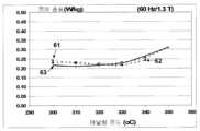
도 6은 본 발명에 의한 비정질 Si2B16, Si3B15 및 Si4B14 합금 리본에 대한 어닐링 온도 함수로서 60 Hz 여기(excitation) 및 1.3 T 유도(induction)에서의 코어 손실을 나타내는 그래프이다.
도 7은 본 발명에 의한 비정질 Si2B16, Si3B15 및 Si4B14 합금 리본에 대한 어닐링 온도 함수로서 60 Hz 여기(excitation) 및 1.3 T 유도(induction)에서의 여기 전력을 나타내는 그래프이다.
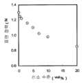
도 8은 본 발명에 의한 비정질 Si2B16, Si3B15 및 Si4B14 합금 리본에 대한 자기 유도(magnetic induction), Bm, 함수로서 60 Hz 여기(excitation)에서의 코어 손실을 나타내는 그래프이다.
도 9는 본 발명에 의한 비정질 Si2B16, Si3B15 및 Si4B14 합금에 대한 자기 유도(magnetic induction), Bm, 함수로서 60 Hz 여기(excitation)에서의 여기 전력을 나타내는 그래프이다.
BRIEF DESCRIPTION OF THE DRAWINGS The present invention will become more fully understood with reference to the following detailed description of preferred embodiments and the accompanying drawings, in which:
1 is a photograph showing defects such as a split line and a face line formed on the ribbon surface during casting.
2 is a diagram showing the surface tension of a given molten alloy in the Fe-Si-B phase diagram. The indicated number represents the surface tension (N / m) of the molten alloy.
3 is a photograph showing a wavy pattern observed on the cast ribbon surface. The amount of lambda is the wave-length of the waveform pattern.
4 is a graph showing the molten alloy surface tension as a function of oxygen concentration, around the molten alloy-ribbon interface.
5 is a diagram showing a transformer core with an over-wrap joint.
Figure 6 is a graph showing core loss at 60 Hz excitation and 1.3 T induction as an annealing temperature function for amorphous Si2 B16 , Si3 B15 and Si4 B14 alloy ribbons according to the present invention. to be.
7 is a graph showing the excitation power at 60 Hz excitation and 1.3 T induction as an annealing temperature function for amorphous Si2 B16 , Si3 B15 and Si4 B14 alloy ribbons according to the invention, to be.
Figure 8 shows the magnetic induction for the amorphous Si2 B16 , Si3 B15 and Si4 B14 alloy ribbon according to the invention, Bm , the core loss at 60 Hz excitation as a function Graph.
9 is a graph showing the magnetic induction, Bm , excitation power at 60 Hz excitation as a function of the amorphous Si2 B16 , Si3 B15 and Si4 B14 alloys according to the invention, to be.
비정질 합금 리본은 미국 특허 제 4,142,571호에서 교시하고 있는 바에 따라, 슬롯 노즐을 통해 회전 칠 바디 표면(rotating chill body surface)으로 배출된(eject) 용융 합금에 의해 제조될 수 있다. 상기 칠 바디 표면을 향하는 리본 표면은 칙칙해(윤이 없는,dull) 보이지만, 분위기(atmosphere)를 향하는 맞은편 면(opposite side)의 표면은 용융 합금의 액상 특성을 반영하여 빛난다. 후술하는 기재에서, 이 면을 또한, 캐스트 리본의 "광택면(shiny side)"이라 하기도 한다. 용융된 합금의 표면 장력이 낮은 경우에, 소량의 용융 합금 스플래시(splash)가 노즐 표면에 달라붙어서 빨리 고화되며, 그 결과 리본 길이 방향을 따라 형성되고 상기 리본의 광택면에 페이스 라인, 스플리트 라인 및 스크래치-같은 라인의 표면 결함이 생긴다. 상기 스플리트 라인은 리본 두께를 가로질러 투과한다. 스플리트 라인 및 페이스 라인의 예는 도 1에 나타낸다. 이는 리본의 연자성 특성(soft magnetic properties)을 강등시킨다. 더한 손상은 캐스트 리본이 상기 결함 위치에서 스플리트(split)되고 파손되는 경향이 있다는 것이며, 이로 인하여 리본 캐스팅이 종결(termination)된다.
The amorphous alloy ribbon may be produced by a molten alloy ejected through a slot nozzle onto a rotating chill body surface as taught in U.S. Patent No. 4,142,571. The surface of the ribbon facing the quartz body surface looks dull but the surface of the opposite side facing the atmosphere shines reflecting the liquid phase properties of the molten alloy. In the description to follow, this side is also referred to as the "shiny side" of the cast ribbon. When the surface tension of the molten alloy is low, a small amount of molten alloy splash sticks to the nozzle surface and solidifies quickly, resulting in the formation along the length of the ribbon and the face of the ribbon, And scratch-like line surface defects. The splitter line penetrates across the ribbon thickness. An example of a spline line and a face line is shown in Fig. This degrades the soft magnetic properties of the ribbon. The additional damage is that the cast ribbon tends to split and break at the defect location, thereby terminating the ribbon casting.
추가적인 관찰로 다음 사항이 확인되었다: 캐스팅 도중에, 캐스팅 시간에 따라 표면 결함의 수, 표면 결함의 길이 및 깊이가 증가되었다. 이러한 진행은 결함 길이가 5mm 내지 200mm이고, 결함 깊이가 0.4 ×t㎛ 미만이며, 결함 수가 리본의 길이 방향을 따라 0.05 ×w미만인 경우에 느려짐을 발견하였으며,t및 w는 캐스트 리본의 두께 및 폭이다. 따라서, 리본 파손 발생이 또한 낮아졌다. 반면에, 리본 길이 방향을 따른 결함 수가 0.05 ×w를 초과하는 경우에, 결함 크기가 증가하며, 그 결과 리본이 파손되었다. 이는 리본 파손이 없는 연속 캐스팅을 위해서, 노즐 표면에서 용융된 합금 스플래시의 발생 정도(incidence)를 최소화할 필요가 있음을 나타낸다. 다수의 시험 후에, 본 발명자는 용융 합금의 표면 장력을 높은 수준으로 유지하는 것이 용융된 합금의 스플래시를 감소시키는데 중요함을 발견하였다.
Additional observations confirmed the following: During casting, the number of surface defects, length and depth of surface defects increased with casting time. This progress was found to be slow when the defect length was 5 mm to 200 mm, the defect depth was less than 0.4 xt m and the number of defects was less than 0.05 xw along the length of the ribbon,t andw were the thickness and width of the cast ribbon to be. Therefore, the occurrence of ribbon breakage was also lowered. On the other hand, when the number of defects along the ribbon length direction exceeds 0.05 xw , the defect size increases, and as a result, the ribbon is broken. This indicates that, for continuous casting without ribbon breakage, the incidence of molten alloy splashes on the nozzle surface needs to be minimized. After a number of tests, the inventors have found that maintaining the surface tension of the molten alloy at a high level is important in reducing the splash of the molten alloy.
예를 들어, 표면 장력이 1.0N/m이고, Fe81.4Si2B16C0.6의 화학적 조성을 가지며 용융온도가 1,350℃인 용융된 합금과 표면 장력이 1.3 N/m이고, Fe81.7Si4B14C0.3의 화학적 조성을 가지며 용융온도가 1,350℃인 용융된 합금의 용융된 합금의 표면 장력 효과가 비교되었다. Fe81.4Si2B16C0.6의 용융 합금이 Fe81.7Si4B14C0.3 합금에 비하여 노즐 표면에 더 많은 스플래시를 나타내었으며, 그 결과 캐스팅 시간이 짧아졌다. 리본 표면을 조사한 경우에, Fe81.4Si2B16C0.6 합금에 기초한 리본이 리본의 1.5m 내에서 수개의 더 많은 결함을 가졌다. 반면에, Fe81.7Si4B14C0.3 합금에 기초한 리본에서는 이러한 결함이 관찰되지 않았다. 많은 다른 합금을 용융된 합금의 표면 장력 효과에 대하여 조사한 결과, 용융된 합금의 표면 장력이 1.1N/m 미만인 경우에, 용융된 합금의 스플래시가 빈번하였으며, 1.5m의 리본 길이 이내의 결함 수가 0.05 xw를 초과하였다. 노즐 표면을 표면 코팅 혹은 폴리싱(polishing) 처리하여 노즐 표면상의 고화된 용융 합금 스플래시를 최소화하기 위한 노력은 실패하였다. 그 후, 발명자들은 인터페이스 주위의 산소 농도를 조절함으로써, 용융 합금과 리본 사이의 인터페이스에서 용융된 합금의 표면 장력을 변화시키는 방법을 개발하였다.For example, if the surface tension of1.0N / m, Fe 81 .4 Si 2
그 후, 본 발명자들은 캐스트 비정질 리본의 포화 자기유도가 1.60T를 초과하는 화학 조성의 발견하였으며, 이는 본 발명의 일 견지이다. 상기 요구조건을 만족하는 합금 조성은 FeaSibBcCd (여기서, 80.5≤a≤83 at.%, 0.5≤b≤6 at.%, 12≤c≤16.5 at.%, 0.01≤d≤1 at.%이고,a+b+c+d= 100임)로 나타내어지며, 상업적인 원료 물질에서 통상적으로 발견되는 불순물, 예를 들어, 철(Fe), 규소철(ferrosilicon, Fe-Si) 및 붕소철(ferroboron, Fe-B)을 갖는다.
Thereafter, the present inventors found a chemical composition with a saturation magnetic induction of the cast amorphous ribbon exceeding 1.60 T, which is an aspect of the present invention. The alloy composition that satisfies the above requirement is Fea Sib Bc Cd where80.5 a 83 at.%,0.5 b 6 at.%, 12c 16.5 at.%, 0.01d ≤1 at.%, and,a +b +c +d = 100 Im) is represented by, an impurity normally found in the commercial raw materials, for example, iron (Fe), silicon iron (ferrosilicon, Fe-Si) And ferroboron (Fe-B).
Si 및 B 함량에 대하여, 상기 목적에 다음의 화학적 제한이 보다 바람직함을 발견하였다:b≥166.5×(100-d)/100-2a 및c≤a-66.5×(100-d)/100.
It has been found that the following chemical limitations are more preferable for the above objects with respect to Si and B content:b? 166.5占 100-d / 100-2a andc? A -66.5 占 100-d / 100 .
또한, 불순물 및 의도적으로 첨가된 미량 원소에 대하여, 주어진 함량 범위를 갖는 다음의 원소가 바람직함을 발견하였다: Mn 0.05-0.30 wt.%, Cr 0.01-0.2 wt.%, Cu 0.005-0.20 wt.%.
It has also been found that, for impurities and intentionally added trace elements, the following elements with a given content range are preferred: Mn 0.05-0.30 wt.%, Cr 0.01-0.2 wt.%, Cu 0.005-0.20 wt. %.
나아가, 20 at.%미만의 Fe은 Co로 임의로 대체되었으며, 10 at.% 미만의 Fe은 Ni로 임의로 대체되었다.
Furthermore, less than 20 at.% Of Fe was replaced by Co, and less than 10 at.% Of Fe was replaced by Ni.
상기 세 패러그래프에서 주어진 조성 범위를 선택한 이유는 다음과 같다: 80.5 at.% 미만의 Fe 함량 "a"으로 1.60 T미만의 포화 자기 유도수준이 되었으며, 83 at.%를 초과하는 "a"에서 합금의 열 안정성 및 리본 성형성(formability)이 감소되었다. Fe을 최고 20 at.% Co 및/또는 최고 10 at.% Ni로 대체함으로써 1.60 T를 초과하는 포화 자기유도 달성에 유리하였다. Si는 Si≥0.5 at.% 그리고 6 at.% 미만에서 리본 성형성을 개선하고 이의 열 안정성을 향상시키며 구상하는 포화 자기유도 수준 및 높은 B-H 방형비(squareness ratio)이 달성된다. B는 12 at.% 초과 그리고 16.5 at.% 미만에서 합금의 리본 성형성 및 이의 포화 자기 유도에 우호적으로 기여하며, 상기 농도 보다 많은 경우에는 상기 우호적인 효과가 감소된다. 이들 내용을 도 2의 상태도(phase diagram)에 정리하였으며, 여기서 영역 1은 용융된 합금의 표면 장력이 1.1N/m이상이며, 영역 2는 용융된 합금의 표면 장력이 1.3N/m를 초과함을 명백하게 나타낸다. 화학 조성에서, 도 2의 영역 1은 FeaSibBcCd(식 중, 80.5≤a≤83 at.%, 0.5≤b≤6 at.%, 12≤c≤16.5 at.%, 0.01≤d≤1 at.%이며,a+b+c+d= 100임)로 규정되며, 영역 2는 FeaSibBcCd(식 중, 80.5≤a≤83 at.%, 0.5≤b≤6 at.%, 12≤c≤16.5 at.%, 0.01≤d≤1 at.%이며,a+b+c+d= 100 그리고b≥166.5×(100-d)/100-2a및c≤a-66.5×(100-d)/100으로 규정된다. 도 2에서, 공융 조성(eutectic composition)은 굵은 파선(dashed line)으로 나타내었으며, 이는 용융된 합금의 표면 장력이 합금 시스템의 공융 조성에 가까이에서 낮음을 나타낸다.
The reasons for choosing the given composition range in the three paragraphs are as follows: Satisfactory magnetic induction level of less than 1.60 T with an Fe content "a" of less than 80.5 at.%, And "a" exceeding 83 at.% The thermal stability of the alloy and the ribbon formability were reduced. By replacing Fe with up to 20 at.% Co and / or up to 10 at.% Ni, it was advantageous to achieve saturation magnetic induction in excess of 1.60 T. Si improves the ribbon formability and improves its thermal stability at Si > 0.5 at.% And less than 6 at.%, And a splayed saturation magnetic induction level and a high BH squareness ratio are achieved. B favorably contributes to the ribbon moldability of the alloy and its saturation magnetic induction at greater than 12 at.% And less than 16.5 at.%, Where the favorable effect is reduced when the concentration is greater than the above concentration. 2, wherein the surface tension of the molten alloy is greater than 1.1 N / m and the surface tension of the molten alloy is greater than 1.3 N / m . In the chemical composition, the
C는 0.01 at.% 초과에서 높은 B-H 방형비(squareness ratio) 및 높은 포화 자기유도를 달성하는데 효과적이지만, 용융된 합금의 표면 장력은 1at.% C 초과에서 감소되었으며, 0.5 at.%미만의 C가 바람직하다. 첨가된 미량 원소 중에서, Mn은 용융된 합금의 표면 장력을 감소시키며, 허용가능한 농도 제한은 Mn < 0.3 wt.%였다. 보다 바람직하게, Mn < 0.2 wt.%이었다. Fe-계 비정질 합금에 함께 존재하는 Mn 및 C는 합금의 열 안정성을 향상시키며, (Mn+C) > 0.05 wt.%가 효과적이었다. Cr 또한, 열 안정성을 향상시키며 Cr > 0.01 wt.%가 효과적이지만 Cr > 0.2 wt.%에서는 합금의 포화 자기유도가 감소하였다. Cu는 Fe에 불용성이며 리본 표면에 석출(precipitate)되는 경향이 있고 용융된 합금의 표면 장력 증가에 도움이 되었으며; Cu > 0.005 wt.%가 효과적이었으며, Cu > 0.02 wt.%가 보다 바람직하지만, C > 0.2 wt.%에서는 리본이 브리틀하게 되었다. Mo, Zr, Hf 및 Nb 그룹으로부터의 하나 이상의 원소가 0.01-5.0 wt.%로 허용가능함을 발견하였다.
C is effective at achieving a high BH squareness ratio and a high saturation magnetic induction at greater than 0.01 at.%, But the surface tension of the molten alloy is reduced at greater than 1 at.% C and less than 0.5 at.% C . Of the added trace elements, Mn decreased the surface tension of the molten alloy, and the allowable concentration limit was Mn <0.3 wt.%. More preferably, Mn <0.2 wt.%. Mn and C in the Fe-based amorphous alloys improve the thermal stability of the alloy and (Mn + C)> 0.05 wt.% Were effective. Cr also improves thermal stability and Cr> 0.01 wt.% Is effective, but at Cr> 0.2 wt.%, The saturation magnetic induction of the alloy decreases. Cu is insoluble in Fe and tends to precipitate on the surface of the ribbon and helps increase the surface tension of the molten alloy; Cu> 0.005 wt.% Was effective, and Cu> 0.02 wt.% Was more preferable, but at C> 0.2 wt.%, The ribbon became brittle. It has been found that at least one element from the Mo, Zr, Hf and Nb groups is acceptable at 0.01 to 5.0 wt.%.
본 발명의 실시형태에 따른 합금은 1,250℃ 내지 1,400℃의 바람직한 용융 온도를 가졌으며, 이 온도 범위에서, 용융된 합금의 표면 장력은 1.1 N/m - 1.6 N/m 범위였다. 1,250℃ 미만에서는, 노즐이 종종 플러그(plug)되는 경향이 있으며, 1,400℃를 초과하면, 용융된 합금의 표면 장력이 감소되었다. 보다 바람직한 융점(melting points)은 1,280℃ -1,360℃ 이었다.
The alloys according to the embodiments of the present invention had a preferred melting temperature of 1,250 ° C to 1,400 ° C, and in this temperature range, the surface tension of the molten alloy ranged from 1.1 N / m to 1.6 N / m. Below 1,250 ° C, the nozzles often tend to be plugged, and above 1,400 ° C, the surface tension of the molten alloy is reduced. More preferred melting points were 1,280 ° C-1,360 ° C.
용융된 합금의 표면 장력 σ은 다음의 식으로 측정되었으며, 이는MetallurgicalandMaterialsTransactions, vol. 37B, pp. 445-456 (Springer 출판, 2006)에서 찾아볼 수 있다 :Surface tension σ of the molten alloy was measured by the following equation, whichMetallurgicalandMaterialsTransactions , vol. 37B, pp. 445-456 (Springer Publishing, 2006): < RTI ID = 0.0 >

식에서,U,G, ρ 및 λ는 각각 칠 바디 표면의 속도, 노즐과 칠 바디 표면 사이의 갭(gap), 합금의 질량 밀도(mass density), 도 3에 나타낸 리본 표면의 광택면에서 관찰되는 파형 패턴의 파장(wave length)이다. 측정된 파장, λ는 0.5 mm-2.5 mm의 범위이다.
In the equation,U ,G , rho and lambda are respectively the speed of the seventh body surface, the gap between the nozzle and the seventh body surface, the mass density of the alloy, It is the wave length of the waveform pattern. The measured wavelength, lambda, ranges from 0.5 mm to 2.5 mm.
본 발명자들은 캐스팅 노즐 바로 아래의 캐스트 리본과 용융된 합금 사이의 인터페이스에 최고 5 vol.%의 농도로 산소 가스를 공급함으로써 표면 결함이 추가적으로 감소될 수 있음을 발견하였다. O2 가스에 대한 상한은 도 4에 나타낸 용융된 합금의 표면 장력 대 O2 농도 데이타에 기초하여 결정되었으며, 이는 5 vol.%를 초과하는 산소가스 농도에서 용융된 합금의 표면 장력이 1.1 N/m 미만이 됨을 나타낸다.
The present inventors have found that surface defects can be further reduced by supplying oxygen gas at a concentration of up to 5 vol.% To the interface between the cast ribbon and the molten alloy directly below the casting nozzle. The upper limit for the O2 gas was determined based on the surface tension of the molten alloy shown in FIG. 4 versus the O2 concentration data, indicating that at an oxygen gas concentration exceeding 5 vol.%, The surface tension of the molten alloy was 1.1 N / m. < / RTI >
발명자들은 본 발명의 실시형태에 따른, 리본 제조방법에서 10㎛ 내지 50㎛의 리본 두께가 얻어짐을 발견하였다. 두께가 10㎛미만인 리본은 형성하기 어려웠으며, 두께가 50㎛를 초과하는 리본 두께는 리본의 자기적 특성이 손상되었다.
The inventors have found that ribbon thicknesses of 10 [mu] m to 50 [mu] m are obtained in the ribbon manufacturing method according to the embodiment of the present invention. Ribbons having a thickness of less than 10 mu m were difficult to form, and ribbon thicknesses exceeding 50 mu m were damaged in the magnetic properties of the ribbon.
본 발명의 실시형태에 따른, 제조방법은 실시예 4에 나타낸 바와 같이, 광범위한 비정질 합금 리본에 적용할 수 있었다.
The manufacturing method according to the embodiment of the present invention can be applied to a wide range of amorphous alloy ribbons as shown in Example 4. [
놀랍게도, 코어 재료의 포화 자기 유도가 증가하는 경우에, 코어 손실이 일반적으로 증가한다는 기대와 달리, 강자성 비정질 합금 리본이 낮은 자기 코어 손실을 나타내었다. 예를 들어, 본 발명의 실시형태에 따른, 320℃ 내지 330℃의 온도에서 어닐링되고, 스트립의 길이 방향을 따라 1,500 A/m의 자기장이 적용된, 강자성 비정질 합금 리본의 직선 스트립(straight strips)은 60 Hz 및 1.3 T 유도(induction)에서 측정되는 경우에, 0.14 W/kg 미만의 자기 코어 손실을 나타내었다.
Surprisingly, when the saturation magnetic induction of the core material increases, unlike the expectation that the core loss generally increases, the ferromagnetic amorphous alloy ribbon exhibits a low magnetic core loss. For example, straight strips of ferromagnetic amorphous alloy ribbon, annealed at a temperature of 320 ° C to 330 ° C and applied with a magnetic field of 1,500 A / m along the length of the strip, according to an embodiment of the present invention When measured at 60 Hz and 1.3 T induction, the magnetic core loss was less than 0.14 W / kg.
직선 스트립에서의 낮은 자기 코어 손실은 자기 리본(magnetic ribbon)을 권취하여 제조되는 자기 코어에서의 상응하는 낮은 자기 코어 손실을 의미한다. 그러나, 코어 권취 도중에 유발되는 기계적 스트레스(mechanical stress)로 인하여, 권취된 코어는 항상 이의 직선 스트립 형태보다 높은 자기 코어 손실을 나타낸다. 권취된 코어의 코어 손실 대 직선 스트립의 코어 손실 비율은 빌딩 팩터(building factor, BF)로 칭하여진다. 최적으로 디자인된 상업적으로 이용가능한 트랜스포머 코어베이스 비정질 합금 리본에 대한 상기 BF 값은 약 2이다. 명백하게, 낮은 BF가 바람직하다. 본 발명의 추가적인 실시형태에 따르면, 오버-랩 조인트를 갖는 트랜스포머 코어는 본 발명의 실시형태에 따라 제조된 비정질 합금 리본을 사용하여 제조되었다. 제조되고 시험된 코어의 치수를 도 5에 나타낸다.The low magnetic core loss in the straight strip means the corresponding low magnetic core loss in the magnetic core produced by winding a magnetic ribbon. However, due to the mechanical stress induced during core winding, the wound core always exhibits a higher magnetic core loss than its linear strip form. The core loss ratio of the wound core versus the core loss ratio of the straight strip is referred to as the building factor (BF). The BF value for an optimally designed commercially available transformer core-based amorphous alloy ribbon is about 2. Obviously, low BF is desirable. According to a further embodiment of the present invention, a transformer core with an over-wrap joint is manufactured using an amorphous alloy ribbon made according to an embodiment of the present invention. The dimensions of the cores produced and tested are shown in FIG.
표 6 및 7 그리고 도 6 및 8에 나타낸 바와 같이, 코어 손실 수준은 비정질 Fe81.7Si2B16C0.3(이하 Si2B16 합금), Fe81.7Si3B15C0.3(이하 Si3B15 합금) 및 Fe81.7Si4B14C0.3(Si4B14합금) 합금 리본에 기초한 트랜스포머 코어와 대략 동일하였으나, 더 높은 Si 함량을 갖는 합금으로된 트랜스포머 코어는 다음의 2가지 이로운 특징을 나타내었다. 첫째, 도 7에 나타내 바와 같이, 2 at.% Si를 함유하는 비정질 합금에 비하여 3-4 at.% Si를 함유하는 비정질 합금에서, 여기 전력이 낮은 어닐링 온도가 훨씬 넓었다. 둘째, 도 8 및 9에 나타낸 바와 같이, 300℃ 내지 335℃의 온도 범위에서 어닐링되고, 리본 길이 방향을 따라 자기장이 적용된, 3-4 at.% Si를 함유하는 비정질 합금 리본으로된 트랜스포머 코어는 실온에서 최고 1.5 - 1.55 T로 작동되었으며, 반면에 2 at.% Si를 함유하는 비정질 합금은 최고 약 1.45 T로 작동되었다. 이 차이는 트랜스포머 크기를 감소시키는데 중요하다. 작동 유도(operating induction)의 0.1 T 증가시, 트랜스포머의 크기가 5-10% 감소될 수 있는 것으로 예측된다. 나아가, 여기 전력이 낮은 경우에, 트랜스포머의 품질이 향상된다. 기술된 기술상의 이점에 비추어, 본 발명의 실시형태에 의한 조성을 갖는 트랜스포머 코어가 시험되었으며, 그 결과 FeaSibBcCd (81≤a≤82.5 at.%, 2.5≤b≤4.5 at.%, 12≤c≤16 at.%, 0.01≤d≤1 at.%이고,a+b+c+d= 100임)로 나타내어지고,b≥166.5 ×(100 -d) / 100 - 2a 및c≤a-66.5×(100 -d)/100의 관계를 만족하는 화학 조성으로된 합금에서 최적의 트랜스포머 성능이 달성됨을 나타내었다.As shown in Tables 6 and 7 and FIGS. 6 and 8, the core loss level was found to be amorphous Fe81.7 Si2 B16 C0.3 (hereinafter Si2 B16 alloy), Fe81.7 Si3 B15 C0.3 Si3 B15 alloy) and Fe81.7 Si4 B14 C0.3 (Si4 B14 alloy) alloy transformer cores, the transformer core made of an alloy with a higher Si content was found to have the following two advantages Respectively. First, as shown in FIG. 7, in the amorphous alloy containing 3 to 4 at.% Si compared to the amorphous alloy containing 2 at.% Si, the annealing temperature at which the excitation power was low was much wider. Second, as shown in FIGS. 8 and 9, a transformer core of amorphous alloy ribbon containing 3-4 at.% Si, annealed in a temperature range of 300 ° C. to 335 ° C. and having a magnetic field applied along the length of the ribbon, It was operated at room temperature up to 1.5 - 1.55 T, whereas the amorphous alloy containing 2 at.% Si was operated at a maximum of about 1.45 T. This difference is important in reducing the transformer size. It is predicted that at 0.1 T increase in operating induction, the size of the transformer could be reduced by 5-10%. Furthermore, when the excitation power is low, the quality of the transformer is improved. In view of the technical advantages described, a transformer core having a composition according to an embodiment of the present invention was tested and found to be Fea Sib Bc Cd (81? A? 82.5 at.%, 2.5?B? 4.5 at..%, 12≤ c ≤16 at% , 0.01≤ d ≤1 at% and,a +b +c +d = 100 Im) is represented by, 166.5b≥ × (100 -.d) / 100 - 2a And an optimum transformer performance was achieved in an alloy having a chemical composition satisfying the relationship ofc? A -66.5 x (100-d ) / 100.
실시예 1Example 1
본 발명의 실시형태에 의한, 화학적 조성을 갖는 잉곳(ingots)을 준비하고 회전 칠 바디(rotating chill body)에서 1,350℃에서 용융된 금속으로부터 캐스트되었다. 캐스트 리본의 폭은 10mm 였으며, 이의 두께는 22-24 ㎛범위였다. 화학적 분석은 리본이 0.10 wt.%의 Mn, 0.03 wt.%의 Cu 및 0.05 wt.%의 Cr을 함유함을 나타내었다. CO2 가스와 산소의 혼합물을 용융된 합금과 캐스트 리본 사이의 인터페이스 가까이에 불어넣었다. 용융된 합금과 캐스트 리본 사이의 인터페이스 가까이의 산소 농도는 3vol%였다. 용융된 합금의 표면 장력, σ는 식 σ= U2 G3 ρ/ 3.6 λ2을 사용하여 캐스트 리본의 광택면 상의 파형 패턴의 파장을 측정하여 알아내었다. 리본 길이 방향을 따라 1.5m 이내의 리본 표면 결함의 수는 캐스트를 시작한 후 30분에 측정되었으며, 표면 결함의 최대 수, N을 표 1에 나타내었다. 상기 리본으로부터의 단일 스트립(strips) 컷은 스트립 길이 방향을 따라 1500 A/m의 자기장을 적용하여 300℃-400℃에서 어닐링되었으며, 열-처리된 스트립의 자기적 특성(magnetic properties)은 ASTM 스탠다드 A-932에 따라 측정되었다. 얻어진 결과를 표 1에 나타내었다. 샘플 번호 1-15는 용융된 합금의 표면 장력 σ, 캐스트 리본 1.5 m에 대한 결함 수, N, 포화 자기 유도(saturation induction), Bs, 및 60 Hz 여기(excitation) 및 1.3 T 유도에서의 자기 코어 손실 W1.3/60에 대하여 본 발명에서 목적하는 사항을 충족한다. 리본 폭이 100 mm임으로, 최대수 N은 5였다. 표 2는 실패한 리본의 예, 샘플 번호 1-6을 나타낸다. 예를 들어, 샘플 번호 1, 3 및 4는 우수한 자기적 특성을 나타내지만, 1.1 N/m 보다 낮은 용융된 합금의 표면 장력으로 인하여 다수의 리본 표면 결함을 나타냈다. 샘플 번호 2, 5 및 6에 대한 용융된 합금의 표면 장력은 1.1 N/m 보다 컸으며, 그 결과 N=0이지만, Bs는 1.60 T 보다 낮았다.Ingots with chemical composition according to an embodiment of the present invention were prepared and cast from molten metal at 1,350 DEG C in a rotating chill body. The width of the cast ribbon was 10 mm, and its thickness ranged from 22 to 24 μm. Chemical analysis indicated that the ribbon contained 0.10 wt.% Mn, 0.03 wt.% Cu and 0.05 wt.% Cr. A mixture of CO2 gas and oxygen was blown near the interface between the molten alloy and the cast ribbon. The oxygen concentration near the interface between the molten alloy and the cast ribbon was 3 vol%. The surface tension of the molten alloy, σ, was determined by measuring the wavelength of the wave pattern on the glossy surface of the cast ribbon using the formula σ = U2 G3 ρ / 3.6 λ2 . The number of ribbon surface defects within 1.5 m along the length of the ribbon was measured 30 minutes after casting and the maximum number of surface defects, N, is shown in Table 1. Single strips cut from the ribbon were annealed at 300 DEG C-400 DEG C applying a magnetic field of 1500 A / m along the length of the strip, and the magnetic properties of the heat- A-932. The obtained results are shown in Table 1. Sample Nos. 1-15 show the surface tension σ of the molten alloy, the number of defects for the cast ribbon 1.5 m, N, saturation induction, Bs , and magnetic susceptibility at 60 Hz excitation and 1.3 T induction The core loss W1.3 / 60 is satisfied with the object of the present invention. Since the ribbon width is 100 mm, the maximum number N is 5. Table 2 shows examples of failed ribbons, Sample Nos. 1-6. For example, Sample Nos. 1, 3 and 4 exhibit good magnetic properties, but exhibit a large number of ribbon surface defects due to the surface tension of the molten alloy below 1.1 N / m. The surface tension of the molten alloy for Sample Nos. 2, 5 and 6 was greater than 1.1 N / m, resulting in N = 0, but Bs was lower than 1.60 T.
[표 1][Table 1]

[표 2][Table 2]

실시예 2Example 2
Fe81.7Si3B15C0.3 조성을 갖는 비정질 합금 리본은 O2 가스 농도를 0.1 vol.%로부터 20 vol.% (공기와 동일)로 변화시킨 것을 제외하고는 실시예 1과 동일한 캐스팅 조건에서 캐스팅하였다. 얻어진 자기적 특성, Bs 및 W1.3/60 그리고 용융된 합금의 표면 장력 σ, 및 표면 결함의 최대 수, N을 표 3에 나타내었다. 시험 결과는 5 vol.%를 초과하는 산소수준이 용융된 합금의 표면 장력을 감소시키며, 이는 결함 수를 증가시켜 캐스팅 시간을 단축시킨다.The amorphous alloy ribbon having the composition of Fe81.7 Si3 B15 C0.3 was the same as that of Example 1 except that the O2 gas concentration was changed from 0.1 vol.% To 20 vol.% Lt; / RTI > Table 3 shows the obtained magnetic properties, Bs and W1.3 / 60, the surface tension σ of the molten alloy, and the maximum number of surface defects, N. Test results show that the oxygen level in excess of 5 vol.% Reduces the surface tension of the molten alloy, which increases the number of defects and shortens the casting time.
[표 3][Table 3]

실시예 3Example 3
소량의 Cu가 실시예 2의 합금에 첨가되었으며, 잉곳이 실시예 1에 따라 비정질 합금 리본으로 캐스트되었다. 자기적 특성, Bs 및 W1.3/60 그리고 용융된 합금의 표면 장력 및 리본에서의 최대 결함수를 표 4에 비교하였다. 0.25 wt.%의 Cu를 갖는 리본은 우수한 자기적 특성을 나타내었지만 브리틀(brittle)하였다. 0.001 wt.%의 Cu를 갖는 리본에서는 용융된 합금의 표면 장력 증가가 관찰되지 않았다.A small amount of Cu was added to the alloy of Example 2, and the ingot was cast into an amorphous alloy ribbon according to Example 1. The magnetic properties, Bs and W1.3 / 60, and the surface tension of the molten alloy and the maximum number of defects in the ribbon are compared in Table 4. Ribbons with 0.25 wt.% Cu showed excellent magnetic properties but were brittle. No increase in the surface tension of the molten alloy was observed in the ribbon with 0.001 wt.% Cu.
[표 4][Table 4]

실시예 4Example 4
리본 폭을 140 mm로부터 254 mm로 변화시키고 리본 두께를 15㎛로부터 40㎛로 변화시킨 것을 제외하고는, 실시예 1과 동일한 조건하에서 Fe81.7Si3B15C0.3 조성의 비정질 합금 리본을 캐스트하였다. 얻어진 자기적 특성, Bs, W1.3/60 및 용융된 합금의 표면 장력,σ 및 표면 결함수, N을 표 5에 나타내었다.An amorphous alloy having a composition of Fe81.7 Si3 B15 C0.3 under the same conditions as in Example 1, except that the ribbon width was changed from 140 mm to 254 mm and the ribbon thickness was changed from 15 μm to 40 μm The ribbon was cast. Table 5 shows the obtained magnetic properties, Bs , W1.3 / 60 and the surface tension of the molten alloy, σ and the number of surface defects.
[표 5][Table 5]

실시예 5Example 5
본 발명의 Fe81.7Si2B16C0.3(Si2B16 합금), Fe81.7Si3B15C0.3(Si3B15 합금) 및Fe81.7Si4B14C0.3(Si4B14 합금) 리본을 이용하여, 오버-랩 조인트를 갖는 트랜스포머 코어를 제조하였다. 코어 치수는 도 5에 나타내었다. 상기 트랜스포머는 리본의 길이 방향을 따라 2,000 A/m의 자기장을 적용하여, 1시간 동안 300℃-350℃의 온도 범위로 어닐링하였다. 코어 손실 및 트랜스포머에 에너지를 부여하는 전력인 여기 전력은 트랜스포머 코어의 어닐링 온도에 의존하며, 이를 도 6 및 7에 나타내었으며, 비정질 Si2B16 리본은 커브 61 (도 6) 및 71 (도 7), Si3B15합금 리본은 커브 62 (도 6) 및 72 (도 7) 그리고 본 발명에 의한 Si4B14 합금 리본은 커브 63 (도 6) 및 73 (도 7)로 각각 나타내었다. 상기 코어는 60 Hz 및 1.3 T 유도(induction)에서 여기되었다(excite). Si2B16, Si3B15 및 Si4B14 합금 리본에 대한 디지털 데이타를 또한 하기 표 6에 나타낸다:Of the present invention,Fe 81 .7 Si 2 B 16 C 0 .3 (Si 2
[표 6][Table 6]

도 8 및 9는 60 Hz 여기(excitation)하에서, 유도 수준(induction level), Bm의 함수로서, 커브 81 (도 8) 및 91 (도 9)로 나타낸 Si2B16 합금 리본, 커브 82 (도8) 및 92 (도9)로 나타낸 Si3B15 합금 리본 및 커브83 (도8) 및93 (도9)으로 나타낸 Si4B14 합금 리본에 기초한 코어 손실 및 여기 전력을 나타낸다. 상기 코어는 리본의 길이 방향을 따라 2,000 A/m의 자기장을 적용하여, 1시간 동안 300℃에서 어닐링하였다. Si2B16, Si3B15 및 Si4B14 합금 리본에 대한 디지털 데이타를 또한 하기 표 7에 나타낸다:Figures 8 and 9 show the Si2 B16 alloy ribbon, curves 81 (Figure 8) and 91 (Figure 9) as a function of induction level, Bm, under 60 Hz excitation, 8) and 92 (Fig. 9) Si3 B15 alloy ribbon and the curve83 (Fig.8) and93 (Fig.9) Si4 B14 represents a loss and excitation power core based on the alloy ribbon represented by the represented by. The core was annealed at 300 DEG C for 1 hour by applying a magnetic field of 2,000 A / m along the longitudinal direction of the ribbon. The digital data for Si2 B16 , Si3 B15 and Si4 B14 alloy ribbons is also shown in Table 7 below:
[표 7][Table 7]

본 발명의 실시형태에 대하여 나타내고 기술하였으나, 이 기술분야의 기술자는 본 발명의 원리 및 기술적 사상의 범위 내에서 이들 실시형태를 변형할 수 있으며, 이들의 범위는 특허청구범위 및 이의 균등물에 의해 규정됨을 이해할 것이다.It will be understood by those skilled in the art that various changes in form and details may be made therein without departing from the spirit and scope of the invention as defined by the appended claims and equivalents thereof You will understand that it is prescribed.
Claims (22)
Translated fromKorean리본은 용융된 합금의 표면의 장력이 1.1N/m이상인, 용융된 상태의 합금으로부터 캐스트되며;
상기 리본은 리본 길이, 리본 두께, 리본 폭, 및 캐스팅 분위기 면(casting atmosphere side)을 향하는 리본 표면을 가지며;
상기 리본은 캐스팅 분위기 면을 향하는 상기 리본 표면에 형성되는 리본 표면 결함을 가지며;
상기 리본 표면 결함은 결함 길이, 결함 깊이 및 결함 발생 빈도로 측정되며;
상기 결함 길이는 리본의 길이 방향을 따라, 5mm 내지 200mm이며, 상기 결함 깊이는 0.4 ×t㎛ 미만이며, 상기 결함 발생 빈도는 리본 길이 1.5m 이내에서 0.05 ×w배(times) 미만이며,t는 각각 리본 두께(thickness) 그리고w는 mm의 리본 폭(width)이며;
상기 리본은 어닐링된, 직선 스트립 형태에서, 60 Hz 및 1.3 T 유도 수준(induction level)에서 측정된 경우에, 0.14 W/kg 미만의 자기 코어 손실을 나타내며, 1.60T를 초과하는 포화 자기유도를 가지며, 어닐링된, 권취된 트랜스포머 코어 형태에서, 60 Hz 및 1.3 T 유도 수준에서 측정된 경우에, 0.3 W/kg 미만의 코어 자기 손실 및 0.4 VA/kg 미만의 여기 전력을 나타내는, 강자성 비정질 합금 리본.
Fe a Si b B c C d (expression, 80.5≤ a≤ 83 at.%, 0.5≤ b ≤6 at.%, 12≤ c ≤16.5 at.%, 0.01≤ d ≤1 at.% , And,a +b +c +d = 100) and an alloy having incidental impurities,
The ribbon is cast from a molten alloy in which the tensile strength of the surface of the molten alloy is at least 1.1 N / m;
The ribbon having a ribbon length, a ribbon thickness, a ribbon width, and a ribbon surface facing the casting atmosphere side;
The ribbon having ribbon surface defects formed on the surface of the ribbon facing the casting atmosphere surface;
The ribbon surface defects are measured by defect length, defect depth, and defect occurrence frequency;
In the longitudinal direction of the defect length of ribbon, and 5mm to 200mm, and the depth of the defect is less than 0.4 ×t is less than ㎛, the defect incidence ribbon length 0.05 ×w times (times) within 1.5m,t is The thickness of each ribbon andw is the ribbon width in mm;
The ribbon exhibits a magnetic core loss of less than 0.14 W / kg when measured at an induction level of 60 Hz and 1.3 T in an annealed, straight strip form and has a saturation magnetic induction in excess of 1.60 T Wherein the ferromagnetic amorphous alloy ribbon exhibits a core magnetic loss of less than 0.3 W / kg and an excitation power of less than 0.4 VA / kg when measured at 60 Hz and 1.3 T induction levels, in the form of an annealed, wound transformer core.
b≥166.5 ×(100 -d) / 100 - 2a 및c≤a-66.5×(100 -d)/100의 관계에 따라, Si 함량 b 및 B 함량 c는 Fe 함량 a 및 C 함량 d와 관련되는, 강자성 비정질 합금 리본.
The method according to claim 1,
166.5 ×b≥ (100 -d) / 100 - 2a andc≤a -66.5 × (100 - d) / 100 based on the relationship, Si content B and content b and c is related to the Fe content and a C content of d Ferromagnetic amorphous alloy ribbon.
미량 원소 Cu를 추가로 포함하며, 상기 Cu의 함량은 0.005 wt% 내지 0.20 wt%인, 강자성 비정질 합금 리본.
The method according to claim 1,
Further comprising a trace element Cu, wherein the content of Cu is from 0.005 wt% to 0.20 wt%.
미량 원소 Mn 및 Cr을 추가로 포함하며, 상기 Mn의 함량은 0.05 wt% 내지 0.30 wt%이고, 상기 Cr의 함량은 0.01 wt% 내지 0.2 wt%인, 강자성 비정질 합금 리본.
The method according to claim 1,
Wherein the content of Mn is from 0.05 wt% to 0.30 wt%, and the content of Cr is from 0.01 wt% to 0.2 wt%. 2. The ferromagnetic amorphous alloy ribbon according to claim 1, wherein the content of Mn is 0.05 wt% to 0.30 wt%.
Fe의 최고 20 at.%는 Co로 대체되거나,
Fe의 최고 10 at.%는 Ni로 대체되거나, 또는
Fe의 최고 20 at.%는 Co로 대체되고 Fe의 최고 10 at.%는 Ni로 대체되는,
강자성 비정질 합금 리본.
The method according to claim 1,
Up to 20 at.% Of Fe may be replaced by Co,
Up to 10 at.% Of Fe is replaced by Ni, or
Up to 20 at.% Of Fe is replaced by Co and up to 10 at.% Of Fe is replaced by Ni.
Ferromagnetic amorphous alloy ribbon.
상기 리본은 1,250℃ 내지 1,400℃의 온도에서 용융된 상태의 합금으로부터 캐스트(cast)되는, 강자성 비정질 합금 리본.
The method according to claim 1,
Wherein the ribbon is cast from an alloy in a molten state at a temperature of from 1,250 ° C to 1,400 ° C.
상기 리본은 용융 합금-리본 인터페이스에서 산소를 5 vol.% 미만으로 함유하는 환경 분위기에서 캐스트되는, 강자성 비정질 합금 리본.
The method according to claim 1,
Wherein the ribbon is cast in an environmental atmosphere containing less than 5 vol.% Oxygen in a molten alloy-ribbon interface.
상기 리본은 FeaSibBcCd (81≤a≤82.5 at.%, 2.5≤b≤4.5 at.%, 12≤c≤16 at.%, 0.01≤d≤1 at.%이고,a+b+c+d= 100임)로 나타내어지고,b≥166.5 ×(100 -d) / 100 - 2a 및c≤a- 66.5×(100 -d)/100의 관계를 만족하는 화학적 조성물을 가지는 합금으로부터 캐스트되며,
상기 리본은 용융된 상태의 합금으로부터 리본을 캐스팅하는 도중에 용융된 금속의 표면 장력을 제어함으로써 감소된 표면 결함을 가져서, 상기 결함 길이는 리본의 길이 방향을 따라, 5mm 내지 200mm이며, 상기 결함 깊이는 0.4 ×t㎛ 미만이며, 상기 결함 발생 빈도는 리본 길이 1.5m 당 0.05 ×w배(times) 미만이며,t는 각각 리본 두께(thickness) 그리고w는 mm의 리본 폭(width)인,
권취된 트랜스포머 코어.
The core being annealed in a magnetic field applied along the length of the ribbon, the core comprising a ferromagnetic amorphous alloy ribbon having an excitation power of less than 0.4 VA / kg and a magnetic core loss of less than 0.3 W / kg when measured at 60 Hz and 1.3 T induction / RTI >
The ribbon isFe a Si b B c C d (81≤ a≤ 82.5 at.%, 2.5≤ b≤ 4.5 at.%, 12≤ c ≤16 at.%, 0.01≤ d ≤1 at.% , And,a +b +c +d = 100 Im) is represented by, 166.5b≥ × (100 -d) / 100 - the chemical composition satisfying the relationshipsd) / 100 - 2a andc≤a - 66.5 × (100 The castle is cast from the alloy,
The ribbon having reduced surface defects by controlling the surface tension of the molten metal during casting of the ribbon from the molten alloy, the defect length being 5 mm to 200 mm along the longitudinal direction of the ribbon,t is less than 0.4 × ㎛, the defect occurrence frequency is less than 0.05 ×w times (times) per 1.5m ribbon length,t is the thickness of each ribbon (thickness), andw is the ribbon width (width) in mm,
Wound transformer core.
상기 합금은 0.005-0.20 wt.% 함량의 Cu, 0.05-0.30 wt.% 함량의 Mn, 및 0.01-0.2 wt.% 함량의 Cr로 이루어진 군으로부터 선택되는 적어도 하나의 미량 원소를 가지며,
Fe의 최고 20 at.%는 Co로 대체되거나,
Fe의 최고 10 at.%는 Ni로 대체되거나, 또는
Fe의 최고 20 at.%는 Co로 대체되고 Fe의 최고 10 at.%는 Ni로 대체되는,
권취된 트랜스포머 코어.
9. The method of claim 8,
Wherein the alloy has at least one trace element selected from the group consisting of Cu in an amount of 0.005-0.20 wt.%, Mn in an amount of 0.05-0.30 wt.%, And Cr in an amount of 0.01-0.2 wt.%,
Up to 20 at.% Of Fe may be replaced by Co,
Up to 10 at.% Of Fe is replaced by Ni, or
Up to 20 at.% Of Fe is replaced by Co and up to 10 at.% Of Fe is replaced by Ni.
Wound transformer core.
상기 리본은 상기 리본의 길이 방향을 따라 적용되는 자기장에서 어닐링되며, 상기 코어는 60 Hz 및 1.3 T 유도에서 측정하는 경우에, 0.35 VA/kg 미만의 여기 전력 및 0.25 W/kg 미만의 자기 코어 손실을 나타내는, 권취된 트랜스포머 코어.
10. The method of claim 9,
The ribbon is annealed in a magnetic field applied along the length of the ribbon, the core having an excitation power of less than 0.35 VA / kg and a magnetic core loss of less than 0.25 W / kg, as measured at 60 Hz and 1.3 T induction ≪ / RTI >
상기 리본은 300℃ 내지 335℃의 온도 범위에서 어닐링되는, 권취된 트랜스포머 코어.
11. The method of claim 10,
Wherein the ribbon is annealed in a temperature range of 300 ° C to 335 ° C.
실온에서 최대 1.5 T의 유도 수준(induction level)에서 작동되는, 권취된 트랜스포머 코어.
11. The method of claim 10,
A wound transformer core operated at an induction level of up to 1.5 T at room temperature.
환상형 형태(toroidal shape) 혹은 반-환상형 형태(semi-toroidal shape)를 갖는, 권취된 트랜스포머 코어.
9. The method of claim 8,
A wound transformer core having a toroidal shape or a semi-toroidal shape.
스텝-랩 죠인트(step-lap joints)를 갖는, 권취된 트랜스포머 코어.
9. The method of claim 8,
Wherein the transformer core has step-lap joints.
오버-랩 죠인트(over-lap joints)를 갖는, 권취된 트랜스포머 코어.
9. The method of claim 8,
A wound transformer core having over-lap joints.
리본을 용융된 합금의 표면의 장력이 1.1N/m이상인, 용융된 상태의 합금으로부터 캐스팅하는 단계;
리본 길이, 리본 두께, 리본 폭을 갖는 리본을 얻는 단계를 포함하며;
상기 리본은 결함 길이, 결함 깊이 및 결함 발생 빈도로 측정되는 리본 표면 결함을 가지며;
상기 결함 길이는 리본의 길이 방향을 따라, 5mm 내지 200mm이며, 상기 결함 깊이는 0.4 ×t㎛ 미만이며, 상기 결함 발생 빈도는 리본 길이 1.5m 이내에서 0.05 ×w배(times) 미만이며,t는 각각 리본 두께(thickness) 그리고w는 mm의 리본 폭(width)이며;
상기 리본은 어닐링된, 직선 스트립 형태에서, 60 Hz 및 1.3 T 유도 수준(induction level)에서 측정된 경우에, 0.14 W/kg 미만의 자기 코어 손실을 나타내며, 1.60T를 초과하는 포화 자기유도를 가지며, 어닐링된, 권취된 트랜스포머 코어 형태에서, 60 Hz 및 1.3 T 유도 수준에서 측정된 경우에, 0.3 W/kg 미만의 코어 자기 손실 및 0.4 VA/kg 미만의 여기 전력을 나타내는, 강자성 비정질 합금 리본의 제조방법.
Fe a Si b B c C d (80.5≤ a≤ 83 at.%, 0.5≤ b ≤6 at.%, 12≤ c ≤16.5 at.%, 0.01≤ d ≤1 at.% , And,a +b +c +d = 100) and an alloy having incidental impurities;
Casting a ribbon from a molten alloy in which the tensile strength of the surface of the molten alloy is at least 1.1 N / m;
Obtaining a ribbon having a ribbon length, a ribbon thickness, and a ribbon width;
The ribbon having ribbon surface defects as measured by defect length, defect depth and defect occurrence frequency;
In the longitudinal direction of the defect length of ribbon, and 5mm to 200mm, and the depth of the defect is less than 0.4 ×t is less than ㎛, the defect incidence ribbon length 0.05 ×w times (times) within 1.5m,t is The thickness of each ribbon andw is the ribbon width in mm;
The ribbon exhibits a magnetic core loss of less than 0.14 W / kg when measured at an induction level of 60 Hz and 1.3 T in an annealed, straight strip form and has a saturation magnetic induction in excess of 1.60 T Of a ferromagnetic amorphous alloy ribbon that exhibits a core magnetic loss of less than 0.3 W / kg and an excitation power of less than 0.4 VA / kg, when measured at 60 Hz and 1.3 T induction levels, in the form of an annealed, wound transformer core. Gt;
b≥166.5 ×(100 -d) / 100 - 2a 및c≤a-66.5×(100-d)/100의 관계에 따라, Si 함량 b 및 B 함량 c는 Fe 함량 a 및 C 함량 d와 관련되는, 강자성 비정질 합금 리본의 제조방법.
17. The method of claim 16,
166.5 ×b≥ (100 -d) / 100 - 2a andc≤a -66.5 × (100-d) / 100 based on the relationship, Si content B and content b and c is related to the Fe content and a C content of d Of the ferromagnetic amorphous alloy ribbon.
미량 원소 Cu를 추가로 포함하며, 상기 Cu의 함량은 0.005 wt% 내지 0.20 wt%인, 강자성 비정질 합금 리본의 제조방법.
17. The method of claim 16,
Further comprising a trace element Cu, wherein the content of Cu is 0.005 wt% to 0.20 wt%.
미량 원소 Mn을 추가로 포함하며, 상기 Mn의 함량은 0.05 - 0.30 wt%이고, 미량 원소 Cr을 포함하며, 상기 Cr의 함량은 0.01 - 0.2 wt%인, 강자성 비정질 합금 리본의 제조방법.
17. The method of claim 16,
Wherein the content of Mn is 0.05 to 0.30 wt% and the content of Cr is 0.01 to 0.2 wt%. The method of producing a ferromagnetic amorphous alloy ribbon according to claim 1,
Fe의 최고 20 at.%는 Co로 대체되거나,
Fe의 최고 10 at.%는 Ni로 대체되거나, 또는
Fe의 최고 20 at.%는 Co로 대체되고 Fe의 최고 10 at.%는 Ni로 대체되는,
강자성 비정질 합금 리본의 제조방법.
17. The method of claim 16,
Up to 20 at.% Of Fe may be replaced by Co,
Up to 10 at.% Of Fe is replaced by Ni, or
Up to 20 at.% Of Fe is replaced by Co and up to 10 at.% Of Fe is replaced by Ni.
Method of manufacturing ferromagnetic amorphous alloy ribbon.
상기 리본은 온도가 1,250℃ 내지 1,400℃인 용융된 상태의 합금으로부터 캐스트되는, 강자성 비정질 합금 리본의 제조방법.
17. The method of claim 16,
Wherein the ribbon is cast from an alloy in a molten state at a temperature in the range of 1,250 DEG C to 1,400 DEG C. 5. A method of making a ferromagnetic amorphous alloy ribbon,
상기 캐스팅은 용융 합금-리본 인터페이스에서 산소를 5 vol.% 미만으로 함유하는 환경 분위기에서 행하여지는, 강자성 비정질 합금 리본의 제조방법.17. The method of claim 16,
Wherein the casting is performed in an environmental atmosphere containing less than 5 vol.% Oxygen at the molten alloy-ribbon interface.
Applications Claiming Priority (3)
| Application Number | Priority Date | Filing Date | Title |
|---|---|---|---|
| US12/923,076 | 2010-08-31 | ||
| US12/923,076US8968489B2 (en) | 2010-08-31 | 2010-08-31 | Ferromagnetic amorphous alloy ribbon with reduced surface defects and application thereof |
| PCT/US2011/049704WO2012030806A1 (en) | 2010-08-31 | 2011-08-30 | Ferromagnetic amorphous alloy ribbon with reduced surface defects and application thereof |
Publications (2)
| Publication Number | Publication Date |
|---|---|
| KR20130094316A KR20130094316A (en) | 2013-08-23 |
| KR101837502B1true KR101837502B1 (en) | 2018-03-13 |
Family
ID=45696378
Family Applications (1)
| Application Number | Title | Priority Date | Filing Date |
|---|---|---|---|
| KR1020137006078AActiveKR101837502B1 (en) | 2010-08-31 | 2011-08-30 | Ferromagnetic amorphous alloy ribbon reduced surface defects and application thereof |
Country Status (10)
| Country | Link |
|---|---|
| US (1) | US8968489B2 (en) |
| EP (1) | EP2612335B1 (en) |
| JP (1) | JP6077446B2 (en) |
| KR (1) | KR101837502B1 (en) |
| CN (1) | CN103125002B (en) |
| BR (1) | BR112013004898B1 (en) |
| PL (1) | PL2612335T3 (en) |
| RU (1) | RU2528623C1 (en) |
| TW (1) | TWI452147B (en) |
| WO (1) | WO2012030806A1 (en) |
Families Citing this family (12)
| Publication number | Priority date | Publication date | Assignee | Title |
|---|---|---|---|---|
| US9604278B2 (en)* | 2012-03-15 | 2017-03-28 | Hitachi Metals, Ltd. | Amorphous alloy ribbon and method of producing the same |
| US20160172087A1 (en) | 2014-12-11 | 2016-06-16 | Metglas, Inc. | Fe-Si-B-C-BASED AMORPHOUS ALLOY RIBBON AND TRANSFORMER CORE FORMED THEREBY |
| TWI532855B (en) | 2015-12-03 | 2016-05-11 | 財團法人工業技術研究院 | Iron-based alloy coating and method for manufacturing the same |
| KR102594635B1 (en) | 2016-11-01 | 2023-10-26 | 삼성전기주식회사 | Magnetic powder for coil component and coil component including the same |
| CN112626427B (en)* | 2017-07-04 | 2022-08-09 | 日立金属株式会社 | Amorphous alloy ribbon |
| DE112018003473T5 (en)* | 2017-07-04 | 2020-03-19 | Hitachi Metals, Ltd. | AMORPHOUS ALLOY TAPE, METHOD FOR PRODUCING THE SAME AND AMORPHOUS ALLOY TAPE |
| CN108411224A (en)* | 2018-04-28 | 2018-08-17 | 河北工业大学 | A kind of preparation method of the iron base amorphous magnetically-soft alloy strip based on HT200 |
| RU2706081C1 (en)* | 2019-07-12 | 2019-11-13 | Федеральное Государственное Унитарное Предприятие "Центральный научно-исследовательский институт черной металлургии им. И.П. Бардина (ФГУП "ЦНИИчермет им. И.П. Бардина") | METHOD OF MAKING A BAND FROM A SOFT MAGNETIC AMORPHOUS ALLOY WITH INCREASED MAGNETIC INDUCTION BASED ON THE Fe-Ni-Si-B SYSTEM |
| CN111001767B (en)* | 2019-12-31 | 2021-10-22 | 武汉科技大学 | A kind of high saturation magnetic induction intensity iron-based amorphous soft magnetic alloy and preparation method thereof |
| CN112593052A (en)* | 2020-12-10 | 2021-04-02 | 青岛云路先进材料技术股份有限公司 | Iron-based amorphous alloy and annealing method of iron-based amorphous alloy |
| CN114244037B (en)* | 2021-12-06 | 2023-09-15 | 青岛云路先进材料技术股份有限公司 | Amorphous alloy motor iron core, preparation method thereof and motor |
| WO2025127964A1 (en)* | 2023-12-14 | 2025-06-19 | National University of Science and Technology “MISIS” | Soft magnetic amorphous fe-co alloy with high saturation magnetization |
Citations (1)
| Publication number | Priority date | Publication date | Assignee | Title |
|---|---|---|---|---|
| JP2006045662A (en)* | 2004-07-05 | 2006-02-16 | Hitachi Metals Ltd | Amorphous alloy ribbon |
Family Cites Families (29)
| Publication number | Priority date | Publication date | Assignee | Title |
|---|---|---|---|---|
| JPS52117002A (en) | 1976-03-26 | 1977-10-01 | Shingijutsu Kaihatsu Jigyodan | Electric signal transmitter using ferromagnetic amorphous ribbon |
| JPS5633452A (en)* | 1979-08-28 | 1981-04-03 | Nippon Steel Corp | Amorphous alloy for transformer |
| US4249969A (en)* | 1979-12-10 | 1981-02-10 | Allied Chemical Corporation | Method of enhancing the magnetic properties of an Fea Bb Sic d amorphous alloy |
| DE3442009A1 (en)* | 1983-11-18 | 1985-06-05 | Nippon Steel Corp., Tokio/Tokyo | AMORPHOUS ALLOY TAPE WITH LARGE THICKNESS AND METHOD FOR THE PRODUCTION THEREOF |
| JPS6124208A (en) | 1984-07-12 | 1986-02-01 | Nippon Steel Corp | Amorphous magnetic material with good magnetic properties |
| US4768458A (en)* | 1985-12-28 | 1988-09-06 | Hitachi, Metals Inc. | Method of producing thin metal ribbon |
| CA2040741C (en) | 1990-04-24 | 2000-02-08 | Kiyonori Suzuki | Fe based soft magnetic alloy, magnetic materials containing same, and magnetic apparatus using the magnetic materials |
| WO1992022398A1 (en) | 1991-06-10 | 1992-12-23 | Allied-Signal Inc. | Rapidly solidified aluminum-magnesium base brazing alloys |
| US5456770A (en) | 1991-07-30 | 1995-10-10 | Nippon Steel Corporation | Amorphous magnetic alloy with high magnetic flux density |
| US5871593A (en)* | 1992-12-23 | 1999-02-16 | Alliedsignal Inc. | Amorphous Fe-B-Si-C alloys having soft magnetic characteristics useful in low frequency applications |
| JP3432661B2 (en)* | 1996-01-24 | 2003-08-04 | 新日本製鐵株式会社 | Fe-based amorphous alloy ribbon |
| US6273967B1 (en)* | 1996-01-31 | 2001-08-14 | Kawasaki Steel Corporation | Low boron amorphous alloy and process for producing same |
| JPH10323742A (en)* | 1997-05-28 | 1998-12-08 | Kawasaki Steel Corp | Soft magnetic amorphous metal ribbon |
| JPH11302823A (en) | 1998-04-17 | 1999-11-02 | Nippon Steel Corp | Method for producing Fe-based amorphous alloy ribbon |
| JP2000054089A (en)* | 1998-07-31 | 2000-02-22 | Kawasaki Steel Corp | Fe-based amorphous alloy with excellent surface properties and magnetic properties |
| JP4623400B2 (en)* | 1999-03-12 | 2011-02-02 | 日立金属株式会社 | Soft magnetic alloy ribbon and magnetic core and apparatus using the same |
| EP1045402B1 (en)* | 1999-04-15 | 2011-08-31 | Hitachi Metals, Ltd. | Soft magnetic alloy strip, manufacturing method and use thereof |
| JP4529106B2 (en)* | 2000-09-11 | 2010-08-25 | 日立金属株式会社 | Method for producing amorphous alloy ribbon |
| US6416879B1 (en) | 2000-11-27 | 2002-07-09 | Nippon Steel Corporation | Fe-based amorphous alloy thin strip and core produced using the same |
| ES2371754T3 (en)* | 2004-07-05 | 2012-01-09 | Hitachi Metals, Ltd. | AMORFA ALLOY-BASED ALLOY BAND |
| JP4636365B2 (en)* | 2004-07-05 | 2011-02-23 | 日立金属株式会社 | Fe-based amorphous alloy ribbon and magnetic core |
| US20060180248A1 (en)* | 2005-02-17 | 2006-08-17 | Metglas, Inc. | Iron-based high saturation induction amorphous alloy |
| JP4771215B2 (en)* | 2005-03-29 | 2011-09-14 | 日立金属株式会社 | Magnetic core and applied products using it |
| CN100545960C (en)* | 2005-03-29 | 2009-09-30 | 日立金属株式会社 | Magnetic core and application product using the same |
| JP5182601B2 (en)* | 2006-01-04 | 2013-04-17 | 日立金属株式会社 | Magnetic core made of amorphous alloy ribbon, nanocrystalline soft magnetic alloy and nanocrystalline soft magnetic alloy |
| JP2007217757A (en)* | 2006-02-17 | 2007-08-30 | Nippon Steel Corp | Amorphous alloy ribbon with excellent magnetic properties and space factor |
| RU2321644C1 (en)* | 2006-08-03 | 2008-04-10 | Институт физики металлов УрО РАН | Magnetically-soft material thermo-magnetic treatment method |
| RU2354734C2 (en)* | 2007-03-06 | 2009-05-10 | Ооо "Феал-Технология" | Amorphous soft magnetic alloy on basis of cobalt |
| PE20170923A1 (en)* | 2010-05-17 | 2017-07-12 | Forum Pharmaceuticals Inc | A CRYSTALLINE FORM OF (R) -7-CHLORO-N- (QUINUCLIDIN-3-IL) BENZO [B] THIOPHENE-2-CARBOXAMIDE MONOHYDRATED HYDROCHLORIDE |
- 2010
- 2010-08-31USUS12/923,076patent/US8968489B2/enactiveActive
- 2011
- 2011-08-30KRKR1020137006078Apatent/KR101837502B1/enactiveActive
- 2011-08-30PLPL11822478Tpatent/PL2612335T3/enunknown
- 2011-08-30BRBR112013004898-0Apatent/BR112013004898B1/enactiveIP Right Grant
- 2011-08-30EPEP11822478.1Apatent/EP2612335B1/enactiveActive
- 2011-08-30WOPCT/US2011/049704patent/WO2012030806A1/enactiveApplication Filing
- 2011-08-30JPJP2013527188Apatent/JP6077446B2/enactiveActive
- 2011-08-30RURU2013114242/07Apatent/RU2528623C1/ennot_activeIP Right Cessation
- 2011-08-30CNCN201180041570.XApatent/CN103125002B/ennot_activeExpired - Fee Related
- 2011-08-30TWTW100131136Apatent/TWI452147B/ennot_activeIP Right Cessation
Patent Citations (1)
| Publication number | Priority date | Publication date | Assignee | Title |
|---|---|---|---|---|
| JP2006045662A (en)* | 2004-07-05 | 2006-02-16 | Hitachi Metals Ltd | Amorphous alloy ribbon |
Also Published As
| Publication number | Publication date |
|---|---|
| BR112013004898B1 (en) | 2021-09-21 |
| TWI452147B (en) | 2014-09-11 |
| BR112013004898A2 (en) | 2016-05-03 |
| US20120049992A1 (en) | 2012-03-01 |
| TW201229250A (en) | 2012-07-16 |
| HK1183967A1 (en) | 2014-01-10 |
| JP6077446B2 (en) | 2017-02-08 |
| RU2528623C1 (en) | 2014-09-20 |
| JP2013537933A (en) | 2013-10-07 |
| EP2612335A4 (en) | 2018-01-10 |
| US8968489B2 (en) | 2015-03-03 |
| WO2012030806A8 (en) | 2013-04-11 |
| CN103125002A (en) | 2013-05-29 |
| EP2612335B1 (en) | 2019-04-10 |
| PL2612335T3 (en) | 2019-10-31 |
| WO2012030806A1 (en) | 2012-03-08 |
| EP2612335A1 (en) | 2013-07-10 |
| KR20130094316A (en) | 2013-08-23 |
| CN103125002B (en) | 2015-12-09 |
Similar Documents
| Publication | Publication Date | Title |
|---|---|---|
| KR101837502B1 (en) | Ferromagnetic amorphous alloy ribbon reduced surface defects and application thereof | |
| KR101837500B1 (en) | Ferromagnetic amorphous alloy ribbon with reduced surface protrusions, method of casting and application thereof | |
| KR101868013B1 (en) | Ferromagnetic amorphous alloy ribbon and fabrication thereof | |
| JP2002173745A (en) | Fe-Ni-based permalloy, method for producing the same, and cast slab | |
| KR20160020500A (en) | Thin amorphous iron alloy strip | |
| JP6722383B2 (en) | Fe-based amorphous alloy ribbon | |
| HK1183968B (en) | Ferromagnetic amorphous alloy ribbon and fabrication thereof | |
| JP4795900B2 (en) | Fe-Ni permalloy alloy | |
| HK1183967B (en) | Ferromagnetic amorphous alloy ribbon with reduced surface defects and application thereof | |
| HK1183966B (en) | Ferromagnetic amorphous alloy ribbon with reduced surface protrusions, method of casting and application thereof |
Legal Events
| Date | Code | Title | Description |
|---|---|---|---|
| PA0105 | International application | Patent event date:20130308 Patent event code:PA01051R01D Comment text:International Patent Application | |
| PG1501 | Laying open of application | ||
| A201 | Request for examination | ||
| PA0201 | Request for examination | Patent event code:PA02012R01D Patent event date:20160624 Comment text:Request for Examination of Application | |
| E902 | Notification of reason for refusal | ||
| PE0902 | Notice of grounds for rejection | Comment text:Notification of reason for refusal Patent event date:20170919 Patent event code:PE09021S01D | |
| E701 | Decision to grant or registration of patent right | ||
| PE0701 | Decision of registration | Patent event code:PE07011S01D Comment text:Decision to Grant Registration Patent event date:20180119 | |
| GRNT | Written decision to grant | ||
| PR0701 | Registration of establishment | Comment text:Registration of Establishment Patent event date:20180306 Patent event code:PR07011E01D | |
| PR1002 | Payment of registration fee | Payment date:20180307 End annual number:3 Start annual number:1 | |
| PG1601 | Publication of registration | ||
| PR1001 | Payment of annual fee | Payment date:20210218 Start annual number:4 End annual number:4 | |
| PR1001 | Payment of annual fee | Payment date:20250217 Start annual number:8 End annual number:8 |