KR101835673B1 - Electronic mat assembly for roast - Google Patents
Electronic mat assembly for roastDownload PDFInfo
- Publication number
- KR101835673B1 KR101835673B1KR1020160178301AKR20160178301AKR101835673B1KR 101835673 B1KR101835673 B1KR 101835673B1KR 1020160178301 AKR1020160178301 AKR 1020160178301AKR 20160178301 AKR20160178301 AKR 20160178301AKR 101835673 B1KR101835673 B1KR 101835673B1
- Authority
- KR
- South Korea
- Prior art keywords
- heat sink
- burner
- flame
- assembly
- gas
- Prior art date
- Legal status (The legal status is an assumption and is not a legal conclusion. Google has not performed a legal analysis and makes no representation as to the accuracy of the status listed.)
- Active
Links
- 230000002093peripheral effectEffects0.000claimsdescription14
- 238000000034methodMethods0.000claimsdescription4
- 238000010438heat treatmentMethods0.000claimsdescription3
- 235000013372meatNutrition0.000abstractdescription12
- 238000001514detection methodMethods0.000abstractdescription11
- 239000007789gasSubstances0.000description82
- 239000003610charcoalSubstances0.000description35
- 238000007664blowingMethods0.000description8
- 238000003780insertionMethods0.000description8
- 230000037431insertionEffects0.000description8
- 239000000779smokeSubstances0.000description5
- 238000004519manufacturing processMethods0.000description3
- QVGXLLKOCUKJST-UHFFFAOYSA-Natomic oxygenChemical compound[O]QVGXLLKOCUKJST-UHFFFAOYSA-N0.000description2
- 238000004140cleaningMethods0.000description2
- 238000004891communicationMethods0.000description2
- 239000013078crystalSubstances0.000description2
- 239000001301oxygenSubstances0.000description2
- 229910052760oxygenInorganic materials0.000description2
- 230000002159abnormal effectEffects0.000description1
- 238000004378air conditioningMethods0.000description1
- 239000006227byproductSubstances0.000description1
- 230000001276controlling effectEffects0.000description1
- 238000010411cookingMethods0.000description1
- 239000002537cosmeticSubstances0.000description1
- 230000003670easy-to-cleanEffects0.000description1
- 238000010892electric sparkMethods0.000description1
- 235000013305foodNutrition0.000description1
- 239000000446fuelSubstances0.000description1
- 230000005484gravityEffects0.000description1
- 238000007689inspectionMethods0.000description1
- 238000009434installationMethods0.000description1
- 238000012986modificationMethods0.000description1
- 230000004048modificationEffects0.000description1
- 230000035515penetrationEffects0.000description1
- 230000001105regulatory effectEffects0.000description1
- 230000000979retarding effectEffects0.000description1
- 230000000630rising effectEffects0.000description1
- 239000010802sludgeSubstances0.000description1
- 238000003892spreadingMethods0.000description1
Images


Classifications
- F—MECHANICAL ENGINEERING; LIGHTING; HEATING; WEAPONS; BLASTING
- F24—HEATING; RANGES; VENTILATING
- F24C—DOMESTIC STOVES OR RANGES ; DETAILS OF DOMESTIC STOVES OR RANGES, OF GENERAL APPLICATION
- F24C3/00—Stoves or ranges for gaseous fuels
- F24C3/02—Stoves or ranges for gaseous fuels with heat produced solely by flame
- F24C3/027—Ranges
- A—HUMAN NECESSITIES
- A47—FURNITURE; DOMESTIC ARTICLES OR APPLIANCES; COFFEE MILLS; SPICE MILLS; SUCTION CLEANERS IN GENERAL
- A47J—KITCHEN EQUIPMENT; COFFEE MILLS; SPICE MILLS; APPARATUS FOR MAKING BEVERAGES
- A47J36/00—Parts, details or accessories of cooking-vessels
- A47J36/02—Selection of specific materials, e.g. heavy bottoms with copper inlay or with insulating inlay
- A—HUMAN NECESSITIES
- A47—FURNITURE; DOMESTIC ARTICLES OR APPLIANCES; COFFEE MILLS; SPICE MILLS; SUCTION CLEANERS IN GENERAL
- A47J—KITCHEN EQUIPMENT; COFFEE MILLS; SPICE MILLS; APPARATUS FOR MAKING BEVERAGES
- A47J37/00—Baking; Roasting; Grilling; Frying
- A47J37/06—Roasters; Grills; Sandwich grills
- A47J37/07—Roasting devices for outdoor use; Barbecues
- A47J37/0786—Accessories
- F—MECHANICAL ENGINEERING; LIGHTING; HEATING; WEAPONS; BLASTING
- F23—COMBUSTION APPARATUS; COMBUSTION PROCESSES
- F23D—BURNERS
- F23D14/00—Burners for combustion of a gas, e.g. of a gas stored under pressure as a liquid
- F23D14/12—Radiant burners
- F23D14/14—Radiant burners using screens or perforated plates
- F—MECHANICAL ENGINEERING; LIGHTING; HEATING; WEAPONS; BLASTING
- F23—COMBUSTION APPARATUS; COMBUSTION PROCESSES
- F23D—BURNERS
- F23D14/00—Burners for combustion of a gas, e.g. of a gas stored under pressure as a liquid
- F23D14/20—Non-premix gas burners, i.e. in which gaseous fuel is mixed with combustion air on arrival at the combustion zone
- F—MECHANICAL ENGINEERING; LIGHTING; HEATING; WEAPONS; BLASTING
- F24—HEATING; RANGES; VENTILATING
- F24C—DOMESTIC STOVES OR RANGES ; DETAILS OF DOMESTIC STOVES OR RANGES, OF GENERAL APPLICATION
- F24C15/00—Details
- F24C15/10—Tops, e.g. hot plates; Rings
- F—MECHANICAL ENGINEERING; LIGHTING; HEATING; WEAPONS; BLASTING
- F24—HEATING; RANGES; VENTILATING
- F24C—DOMESTIC STOVES OR RANGES ; DETAILS OF DOMESTIC STOVES OR RANGES, OF GENERAL APPLICATION
- F24C3/00—Stoves or ranges for gaseous fuels
- F24C3/08—Arrangement or mounting of burners
- F24C3/085—Arrangement or mounting of burners on ranges
- F—MECHANICAL ENGINEERING; LIGHTING; HEATING; WEAPONS; BLASTING
- F23—COMBUSTION APPARATUS; COMBUSTION PROCESSES
- F23D—BURNERS
- F23D2203/00—Gaseous fuel burners
- F23D2203/10—Flame diffusing means
- F23D2203/103—Flame diffusing means using screens
Landscapes
- Engineering & Computer Science (AREA)
- Chemical & Material Sciences (AREA)
- Combustion & Propulsion (AREA)
- Mechanical Engineering (AREA)
- General Engineering & Computer Science (AREA)
- Food Science & Technology (AREA)
- Baking, Grill, Roasting (AREA)
Abstract
Translated fromKoreanDescription
Translated fromKorean본 발명은 직접착화식 화덕장치용 방열판조립체에 관한 것으로서, 더욱 상세하게는 고기를 구울 때 별도로 숫불을 준비할 필요가 없을 뿐만 아니라, 조립이 간단하고, 조립만 하면 불꽃감지가 용이하도록 된 직접착화식 화덕장치용 방열판조립체에 관한 것이다.The present invention relates to a heat sink assembly for a direct ignition type burner apparatus, and more particularly, to a heat sink assembly for a direct ignition type burner apparatus, and more particularly to a heat sink assembly for direct ignition type burner apparatus, To a heat sink assembly for a cooking appliance.
일반적으로, 숯불을 사용하여 고기를 굽는 고기구이기는 대개 숯불통에 불이 피워진 숯을 담아 이 숯의 열기로써 고기를 굽게 되어 있다. 그런데, 숯불고기구이기는 숯불통에 담겨진 숯을 착화시키는 방법에 따라 2가지로 구분되는바, 예컨대 숯불통에 담긴 숯을 외부에서 별도의 착화장치를 사용하여 착화시킨 다음 실내로 가져와 식탁에 설치된 고기구이기에 숯불통을 결합시켜 사용하도록 한 외부착화식과, 이 외부착화식에서 발전한 것이 식탁에 설치된 고기구이기에 숯불통이 결합된 상태 그대로 두고, 숯불통에 숯을 담은 다음 숯불통 아래에서 가스불을 피워 숯불통의 숯을 착화시키도록 하는 직접착화식으로 분류된다.Generally, a charcoal grill is used to grill meat, and usually charcoal grill is burnt with the charcoal charcoal grill. However, the charcoal box is classified into two types according to the method of igniting the charcoal contained in the charcoal box. For example, the charcoal contained in the charcoal box is ignited from the outside by using a separate ignition device, The charcoal box is combined with the charcoal box, and the charcoal box is combined with the charcoal box. The charcoal box is combined with the charcoal box and the gas is burned under the charcoal box. It is classified as a direct ignition type that causes char to ignite.
그런데, 상기한 바에 따른 직접착화식 고기구이기에서, 식탁에 설치된 고기구이기에서 직접 숯불통의 숯을 착화시킬 수 있게 하기 위해서는 숯불통 아래에 화염을 발생시킬 수 있는 점화장치가 구비되어 있어야 한다. 따라서, 이러한 직접착화식 고기구이기는 상기한 바와 같이 숯불통의 숯을 자체적으로 점화시키기 위한 점화장치가 구비되어 있어야 함으로 인해 그 구조가 복잡할 뿐만 아니라 고난도의 제조 기술을 요구한다.However, in the direct-ignition type meat grilling machine according to the above description, an ignition device capable of generating a flame under a charcoal box must be provided in order to be able to ignite the char of the charcoal box directly from the meat grill installed on the table. Therefore, as described above, the direct-ignition type kink is required to have an ignition device for igniting the charcoal of the charcoal box itself, thereby complicating its structure and requiring a manufacturing technique of high degree.
한편, 일반적으로 상기한 바의 점화장치로서 대개 사용과 설비가 다른 점화기구에 비해 편리한 가스버너를 사용하고 있다. 즉, 본 출원인에 의해 출원되어 등록된 특허등록 제10-1092687호 발명의 명칭 "직접착화식 구이용 화덕장치"의 종래기술에 도시되어 있는 바와 같이, 숯불통 아래에 가스버너를 설치하여 사용하는 것이 통상적인 자체점화식 숯불구이기의 점화장치인 바, 이와 같이 가스버너와 그 연료로서 가스를 사용하므로 인해 여러 가지 문제가 발생되고 있다. 점화수단으로 가스와 가스버너를 사용하는 자체점화식 숯불고기구이기는, 숯을 담아 불을 피우는 숯불통 아래에 가스버너가 배치되고, 이 가스버너에 근접하여 가스버너에서 분출되는 가스를 점화시키기 위한 점화수단이 함께 설치되어 있으며, KS 규격의 가스안전규정에 따라 가스버너의 점화상태를 감지하여 가스버너에서 화염이 감지되지 않는 경우에 가스의 공급을 강제적으로 차단하기 위해 화염감지수단이 설치된 구조로 되어 있다. 또한, 통상적으로 상기 숯불통의 숯이 가스버너에서 전달되는 불꽃에 의해 빠른 속도로 착화되게 하기 위해 바람을 불어주기 위한 송풍기가 갖추어져 있다.On the other hand, in general, a gas burner is used as an ignition device as compared with an ignition device generally used and equipped with different facilities. That is, as shown in the prior art of the "direct-ignition burning furnace device" of the invention, which is filed and registered by the applicant of the present invention, a gas burner is installed under a charcoal canister Since it is an ignition device of a conventional self-ignition type charcoal grill, various problems are caused by using gas as a gas burner and its fuel. A self-ignition type charcoal fire fighting apparatus using a gas and a gas burner as ignition means includes a gas burner disposed below a charcoal tank containing a charcoal and burning, and an ignition means for igniting a gas ejected from the gas burner in proximity to the gas burner And a flame detecting means is provided to detect the ignition state of the gas burner according to the gas safety regulation of the KS standard and forcibly shut off the gas supply when the flame is not detected by the gas burner . In addition, a blower for blowing air is generally provided so that the char of the charcoal tank is quickly ignited by the flame transmitted from the gas burner.
그리고, 상기 가스버너의 화염이 다른 곳으로 빠지지 않고 숯불통으로만 전달되게 함과 더불어, 송풍기에서 송풍되는 바람 역시 상기 숯불통으로만 전달되게 하여 점화효율을 높일 수 있도록 하기 위해, 상기 숯불통이 안착되는 지지대와 숯불통사이가 밀착되어 공기가 외부로 방출되는 것을 방지해 주게 되어 있다.In addition, the flame of the gas burner is not transferred to other places but only to the charcoal tank. In addition, in order to increase the efficiency of ignition by allowing the wind blown from the blower to be transmitted only to the charcoal tank, So that the support bar and the charcoal barrel are brought into close contact with each other to prevent air from being released to the outside.
또한, 상기 숯불통과 가스버너 사이 및 가스버너의 주변에, 가스버너에서 화염이 발생할 수 있게 함과 더불어 가스버너에서 점화가 이루어지게 하는데 필요한 공기를 충분하게 공급해주기 위한 내부공간을 갖춘 구조로 되어 있다.In addition, there is an internal space between the charcoal passing gas burners and the periphery of the gas burner so as to allow flames to be generated in the gas burners and to sufficiently supply the air required for ignition in the gas burners .
그리고, 상기한 바와 같은 종래의 숯불고기구이기에서는 상기 점화수단으로서, 전기적으로 작동하면서 불꽃을 발생시키는 소위, 이그나이터라 불리는 전기스파크발생기구를 사용하고 있다.In the conventional charcoal grilling machine described above, there is used an electric spark generating mechanism called an igniter, which generates a flame while electrically operating, as the ignition means.
그리고, 일단 가스버너를 점화시키기 위해서는 가스공급밸브를 개방시켜 가스가 분출되게 한 상태에서 점화장치를 작동시켜야 하기 때문에, 같이 점화가 이루어지지 않은 경우에도 가스버너에서는 계속하여 가스가 분출되게 되는데, 이때 연소되지 않은 가스는 상기에서 설명한 내부공간속에 정체하여 고이게 되고, 이렇게 가스가 상기 내부공간속에 고여 있는 상태에서 다시 점화시키기 위해 상기의 전기점화장치를 사용하여 불꽃을 발생시키면 가스가 일순간에 연속적으로 연소하면서 폭발하게 된다.In order to ignite the gas burner once, the ignition device must be operated in such a state that the gas is discharged by opening the gas supply valve. Therefore, even if the ignition is not performed, the gas is continuously discharged from the gas burner. The unburned gas stagnates in the above-described internal space, and when the ignition device is used to generate a flame to re-ignite the gas in the internal space, the gas is continuously burned And explodes.
한편, 상기한 바와 다른 경우로서, 가스가 계속하여 공급되고 있는 상태에서 여러 가지 이유로 인하여 가스버너의 화염이 꺼지고, 상기 화염감지봉이 가스버너가 화염을 감지하지 못하게 될 때, 이 화염감지봉이 가스공급밸브를 즉시 차단 작동시키는 것이 아니라, 대개 화염이 꺼진 후 약 20 ~30 초 후에 가스공급밸브를 차단 작동시키게 되는데, 그 동안에는 연소되지 않는 상태에서 가스버너를 통하여 계속하여 가스가 분출하게 된다. 즉, 가스버너에서 불꽃이 발생하지 않을 때 이를 감지한 화염감지봉이 가스공급밸브를 즉시 차단시키는 것이 아니라 소정의 시간간격을 두고 가스공급밸브를 차단시키도록 되어 있으므로, 이와 같이 가스공급밸브가 차단되기까지 가스버너에서 가스가 연소되지 않는 상태로 누출되는 것이다. 그리고, 상기와 같이 누출된 가스는 상기의 내부공간속으로 퍼져 나가게 되는데, 상기 내부공간이 숯불통과 송풍기등에 의해 외부와 대체적으로 차단된 상태이기 때문에, 내부공간속으로 퍼져 나간 가스가 이 공간속에 정체되어 모여있게 된다. 이와 같이 상기 내부공간속에 가스가 고여 있는 상태에서 다시 숯불을 착화시키기 위해 점화장치를 작동시켜 불꽃을 발생시키면, 내부공간속에 고여 있는 가스가 점화되면서 일순간에 많은 양의 가스가 급작스럽게 연소됨으로 인해 순간적으로 폭발하게 되는 위험한 문제가 있는바, 상기 화염감지봉이 손상되면 안전에 큰 단점이 있게 된다.On the other hand, as another case, when the gas is continuously supplied, the flame of the gas burner is turned off for various reasons, and when the flame detecting rod is not able to detect the flame, Rather than immediately shutting off the valve, the gas supply valve is shut down about 20 to 30 seconds after the flame is turned off. During this time, the gas is continuously discharged through the gas burner in the unburned state. That is, when the flame is not generated in the gas burner, the flame detecting bar senses the flame, so that the gas supply valve is shut off at a predetermined time interval instead of immediately shutting off the gas supply valve. The gas will leak out of the gas burner without burning. The gas leaking out as described above spreads into the inner space. Since the inner space is generally blocked by the charcoal blowing blower or the like, the gas spreading into the inner space is stagnated in the space . When the ignition device is operated to generate a flame by igniting the charcoal in a state where the gas is held in the inner space, a gas accumulated in the inner space is ignited, and a large amount of gas is suddenly burned in a moment, There is a danger that the flame detecting rods are damaged.
종래에는 상기 화염감지봉이 가스버너와 인접한 곳에 설치되어 가스버너가 동작하는 동안에는 그 열기에 의해 화염감지봉이 손상되어 그 교체가 빈번하게 이루어 져야 하는 번거러움 및 사후관리 비용이 상승되는 문제점이 있었다.Conventionally, the flame detecting rods are disposed adjacent to the gas burner, and during the operation of the gas burner, the flame detecting rods are damaged due to the heating, so that frequent replacement of the flame detecting rods is required.
또한, 상기 숯불통의 숯이 연소됨에 따라 그 부산물인 재가 발생하게 되는데, 송풍기의 송풍압력 및 중력의 영향으로 그 재가 지지대 측에 위치하게 된다. 따라서, 상기와 같은 재는 위생상 및 미관상 좋지 않은 영향을 미치므로 청소를 자주 해줘야 하는 필요성이 발생하는데, 상기 지지대가 숯불통을 감싸도록 일체형으로 구비되어 청소시 탈착이 불가능하여 청소가 어려운 문제점이 있었다.As the char of the charcoal tank is burned, ash, which is a byproduct of the charcoal tank, is generated. The ash is located on the side of the support by the influence of the blowing pressure and gravity of the blower. Therefore, it is necessary to frequently clean the sanitary ware and the sanitary ware such as the sanitary ware and the cosmetics. Therefore, it is difficult to clean the sanitary ware and the sanitary ware. .
이러한 제반문제점을 해소하기 위해 본 출원인에 의해 등록된 특허등록 제10-1092687호에서는, 외통의 일측면에 설치된 송풍모터와 송풍댐퍼로 이루어진 송풍수단에 의해 외통의 축방향 중간에 위치하도록 설치된 내통지지대로 공급되는 공기의 량을 조절할 수 있을 뿐 아니라, 내통지지대의 송풍수단이 설치된 쪽에 버너점화기가 장착되어 테이블의 상판에 설치된 조작부의 점화신호가 테이블의 내부에 설치된 콘트롤부로 전달되어 불꽃을 점화할 수 있음은 물론, 외통의 타측면에 체결된 산소혼합기를 갖춘 버너바디벤츄리관용 삽입부재가 설치되어 가스와 공기를 공급할 수 있을 뿐만 아니라, 외통의 하부에 설치된 배기필터수단에 의해 공급된 가스와 공기에 의해 조리되면서 발생한 냄새와 연기가 배출되는 한편, 외통의 관통구멍에 설치된 화염감지수단이 콘크롤부에 불꽃을 감지한 신호를 보내게 되면 정상적으로 작동하게 되고 불꽃을 감지하지 못하면 송풍수단에 의한 공기의 공급과 가스의 공급을 차단하도록 된 본체와, 외통의 상부에서 축방향 하부로 끼워져 내통지지대의 상부에 안착된 내통과, 내통의 상부에서 축방향 하부로 삽입되어 내통의 바닥면과 일정한 간격을 두고 안착됨과 더불어 버너점화기에 의해 점화된 화염이 들어오도록 설치된 버너지지대와, 버너지지대의 버너바디안착부에 안착됨과 더불어 내통의 삽입부재안착부와 본체의 버너바디벤츄리관용 삽입부재에 끼워지는 벤츄리관을 갖춘 버너바디와, 버너바디의 상부에 안착되어 불꽃이 방사방향으로 퍼지도록 된 버너헤드와, 버너바디와 버너헤드를 수용하면서 불꽃을 중앙으로 모으도록 버너지지대의 상부에 안착됨과 더불어, 일측면에는 버너바디의 벤츄리관을 수용하도록 벤츄리관안내홈이 형성되고, 이 벤츄리관안내홈과 일정 간격 떨어진 곳에는 화염감지구가 형성되는 한편, 중앙 상부에는 화로 또는 강열받침링으로 화염을 공급할 수 있도록 관통부가 형성된 화로지지대를 포함한다.In order to solve these problems, Patent Registration No. 10-1092687, which is registered by the applicant of the present application, discloses a method for manufacturing an air conditioner, which is provided with a blowing motor provided on one side of an outer cylinder and a blowing means comprising a blowing damper, The burner igniter is mounted on the side where the blowing means of the inner tube support is installed so that the ignition signal of the operating portion provided on the top plate of the table is transmitted to the control portion provided inside the table so as to ignite the flame Not only the gas and air can be supplied by the insertion member for the burner body venturi tube having the oxygen mixer fastened to the other side of the outer cylinder but also the gas and air supplied by the exhaust filter means provided at the lower portion of the outer cylinder The odor and the smoke generated while being cooked are discharged, while the flame generated in the through hole of the outer cylinder A main body which is normally operated when a signal indicating that the flame is sensed in the cone cowl portion and which is operated normally and cuts off the supply of air and the supply of gas by the air blowing means when the flame is not sensed; A burner support which is inserted into the lower portion of the inner cylinder at an upper portion of the inner cylinder and is spaced apart from the bottom surface of the inner cylinder at a predetermined interval and is installed such that a flame ignited by the burner igniter enters, A burner body having a venturi tube which is seated on a burner body seat of the burner body and which is fitted to an insertion member seat portion of the inner tube and a insertion member for a burner body venturi pipe of the main body; The burner head, the burner body and the burner head, and is seated on top of the burner support to center the flame A venturi tube guide groove is formed on the side of the blower to accommodate the venturi tube of the burner body. A flame retarding region is formed at a distance from the guide groove of the venturi tube, and a flame or a heat- Which is provided with a through-hole for supplying the gas.
따라서 화염감지수단이 화염으로부터 이격된 곳에 설치되어 안정성 있게 화염을 감지할 수 있고, 산소혼합기를 갖춘 버너바디벤츄리관용 삽입부재에 버너바디와 버너헤드를 장착하고 분해하는 것이 용이할 뿐만 아니라, 외통의 내통지지대에 장착된 내통과 버너지지대에 의해 지지되는 버너헤드와 버너바디의 청소가 매우 용이하게 되는 한편, 화로지지대에 의해 버너바디와 버너헤드를 수용하면서 불꽃을 중앙으로 모아서 화로의 불꽃 감지는 물론 열효율을 증가시킬 수 있고, 배기필터수단이 외통의 하부에 계단진 플랜지를 갖춘 배기필터수단설치부재를 매개로 설치되어 외통의 제작이 간편하게 되는 한편, 외통과 배기필터수단의 조립이 매우 간단하게 된다.Therefore, the flame detecting means can be installed at a position spaced from the flame and can detect the flame stably, and it is easy to mount and disassemble the burner body and the burner head in the insert member for the burner body venturi tube having the oxygen mixer, It is very easy to clean the burner head and the burner body supported by the inner burner support mounted on the inner tube support, while the burner body and the burner head are housed by the burner support while collecting the flame at the center, And the exhaust filter means is provided through an exhaust filter means attachment member having a stepped flange at the lower portion of the outer cylinder to simplify the manufacture of the outer cylinder and simplify the assembly of the outer cylinder and the exhaust filter means .
또 배기필터수단을 구성하는 나비댐퍼의 상부에 플랜지가 구비되어 배기필터수단을 설치하기 용이함은 물론, 휠터의 하부에는 외측으로 절곡된 환형의 요홈이 형성되어 기름 찌꺼기등을 용이하게 걸러서 모을 수 있음으로 매우 위생적이고 오염이 적게 되는 한편, 내통에 버너지지대가 안착되는 위치결정돌기가 구비되고 버너지지대에는 위치결정홈이 형성되어 내통에 버너지지대를 매우 쉽게 조립할 수 있음은 물론, 버너지지대의 수용부에는 버너점화기에 의해 점화된 화염이 들어오도록 개구가 형성되고, 등각도로 복수개의 공기유입구가 형성되어 불꽃의 점화가 용이하게 되며, 수용부의 상부에 설치된 플랜지에는 관통구멍이 형성된 버너바디안착부가 설치되어 버너바디의 하부로 돌출된 위치결정돌기와 조립이 매우 용이할 뿐만 아니라, 내통지지대의 관통구멍에 설치된 내통지지대수납용 덮개를 들어올리면 외통을 분해하지 않고서도 하부의 배기필터수단을 구성하는 나비댐퍼와 휠터의 청소가 매우 용이하게 된다.Further, the flange is provided on the upper portion of the butterfly damper constituting the exhaust filter means, so that it is easy to install the exhaust filter means. In addition, annular grooves bent outwardly are formed in the lower portion of the filter to collect oil sludge easily. The positioning recesses are formed in the inner cylinder so that the burner support is seated and the positioning recesses are formed in the burner support so that the burner support can be easily assembled to the inner cylinder, An opening is formed to allow the flame ignited by the burner igniter to enter, a plurality of air inlets are formed at an equal angle to facilitate the ignition of the flame, and a flange provided on the upper portion of the receiving portion is provided with a burner body seating portion formed with a through- It is very easy to assemble with positioning projections projected to the lower portion of the burner body, Lifting the inner tube accommodating the support cover, for installation in a through hole of the cleaning zone of the butterfly dampers and the filter constituting the lower portion of FIG exhaust filter means without decomposing the outer tube is very easily.
그러나 이러한 특허등록 제10-1092687호는, 고기를 구울때 흘러내리는 기름에 의해 버너의 화염출구가 막혀서 매우 지저분하게 되어 청소시 시간이 많이 소요되는 문제점이 있었다.However, this Patent Registration No. 10-1092687 has a problem that the flame outlet of the burner is clogged by the oil flowing down when the meat is burned, which is very messy and takes a long time to clean.
또 고기를 구울때 흘러내린 기름을 청소하려면 화로지지대와 버너헤드, 버너바디 및 버너지지대를 분해해서 제거해야만 내통을 들어올려 청소할 수 있어서 청소시에 매우 불편한 문제점이 있었다.Further, in order to clean the oil flowing down while burning meat, the burner support, the burner head, the burner body and the burner support have to be disassembled and removed to lift the inner cylinder, which is very inconvenient for cleaning.
또한 내통을 외통에 조립할 때 외통에 조립된 버너바디벤츄리관용 삽입부재와 내통의 삽입부재안착부와 일치시켜 조립하게 되는바, 이때 버너바디벤츄리관용 삽입부재와 삽입부재안착부의 간극이 발생해서 공기가 유입됨과 더불어 가스가 유출되어 화재가 발생하는등 문제점이 있었다.In addition, when the inner tube is assembled to the outer tube, it is assembled by inserting the insert member for the burner body venturi tube and the insert member for the inner tube assembled in the outer tube. At this time, a gap is generated between the insert member for the burner body and the insert member, There is a problem that a gas is leaked along with the inflow and a fire occurs.
또 외통에 설치된 화염감지수단과 내통의 투시경 및 화로지지대의 화염감지구가 동일한 선상에 위치해야 하지만 조립시 각각의 위치가 틀어져서 화염감지가 제대로 이루어지지 않아 제조립을 해야하는 문제점이 있었다.In addition, although the flame detection means installed in the outer cylinder and the flame detection region of the inner tube's flame sensor and the flame support stand are located on the same line, the flame detection is not properly performed at the time of assembly.
관련 선행기술로는 대한민국 특허등록 제10-1092687호 발명의 명칭 "직접착화식 구이용 화덕장치"가 있다.A related prior art is Korean Patent Registration No. 10-1092687 entitled "direct-ignition burning furnace device ".
본 발명은 상기와 같은 제반 문제점들을 해소하기 위해 안출된 것으로, 고기를 구울 때 별도로 숫불을 준비할 필요가 없을 뿐만 아니라, 조립만 하면 불꽃감지가 용이하도록 된 직접착화식 화덕장치용 방열판조립체를 제공함에 그 목적이 있다.The present invention provides a heat sink assembly for a direct ignition type frying apparatus, which does not need to separately prepare burnt flesh when meat is fired, and can easily detect a flame when assembled. It has its purpose.
상기와 같은 목적을 달성하기 위한 본 발명에 의한 직접착화식 화덕장치용 방열판조립체는, 가스를 이용하여 버너조립체로 불꽃을 토출하여 가열하되, 상기 내통의 상부로 돌출된 위치결정핀으로 끼워지되, 하부면이 내통의 안착부에 안착되어 중앙으로 불꽃이 올라오도록 된 방열판받침대와, 상기 방열판받침대의 상부에 끼워져 안착됨과 더불어 상부가 돔형상으로 이루어지면서 등간격으로 다수개의 관통구멍이 형성된 방열판과, 상기 방열판의 돔부 내측에 밀착되도록 축방향 중심으로 끼워지는 나사못과 너트으로 이루어진 체결수단으로 고정됨과 더불어 복수개가 겹쳐져서 용접된 방열판망으로 이루어진 것을 특징으로 한다.According to another aspect of the present invention, there is provided a heat sink assembly for a direct-ignition type burner apparatus, the burner assembly comprising: a burner assembly for burning and heating a flame using a gas, A heat sink having a lower surface mounted on a seat portion of the inner tube and having a flame rising at a center thereof, a heat sink having a plurality of through holes formed at an upper portion of the heat sink, And a plurality of heat sinks welded to the heat sink, the heat sink being secured to the heat sink by fastening means including screws and nuts fitted in the center of the heat sink in the axial direction so as to be in close contact with the inside of the dome.
본 발명에 의한 직접착화식 화덕장치용 방열판조립체는, 상기 방열판받침대는, 환원형상의 수용부와, 상기 수용부의 바닥에 형성되어 불꽃이 올라오도록 된 관통구멍과, 상기 수용부의 외측면에 관통형성된 불꽃감지구멍과, 상기 수용부에 형성된 관통구멍의 주변 바닥면에 형성되어 버너연결유니트의 위치결정핀이 끼워지면 상기 불꽃감지구멍과 내통의 투시부가 외통의 불꽃감지수단과 함께 일직선상에 위치하도록 하는 위치결정구멍이 형성된 것을 특징으로 한다.The heat sink assembly for a direct-ignition type burner apparatus according to the present invention is characterized in that the heat sink base includes a receiving portion having a reduced shape, a through hole formed on the bottom of the receiving portion to allow the flame to rise, The flame detection hole and the positioning pin of the burner connection unit are fitted on the peripheral bottom surface of the through hole formed in the receiving portion so that the flame detection hole and the transparent portion of the inner tube are positioned on a straight line together with the flame detection means of the outer cylinder A positioning hole is formed.
본 발명에 의한 직접착화식 화덕장치용 방열판조립체는, 상기 돔의 상부 일측에 취부걸이가 구비된 것을 특징으로 한다.The heat sink assembly for a direct ignition type burner apparatus according to the present invention is characterized in that a mounting hook is provided on an upper side of the dome.
상술한 바와 같이 본 발명에 따른 직접착화식 화덕장치용 방열판조립체에 의하면, 고기를 구울 때 별도로 숫불을 준비할 필요가 없을 뿐만 아니라, 조립이 간단함 물론, 조립만 하면 불꽃감지가 용이하게 되는 효과가 있다.As described above, according to the heat sink assembly for a direct-ignition type burner apparatus according to the present invention, it is not necessary to separately prepare a burner for burning meat, and it is easy to assemble. Of course, .
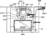
도 1은 본 발명의 1실시예에 따른 직접착화식 구이용 화덕장치의 종단면도이고,
도 2는 도 1의 분해사시도,
도 3은 도 1의 점화부를 나타내는 상세도,
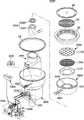
도 4는 도 1의 방열판조립체를 나타내는 사시도,
도 5는 도 4의 분해사시도,
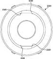
도 6은 도 1의 외통을 나타내는 평면도,
도 7은 도 6의 분해사시도,
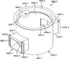
도 8은 도 1의 버너배기관연결부재의 사시도,
도 9는 도 8의 좌측면도,
도 10은 도 8의 우측면도,
도 11은 도 8의 평면도,
도 12는 도 8의 저면도,
도 13은 본 발명의 2실시예에 따른 직접착화식 구이용 화덕장치의 종단면도,
도 14는 도 13의 분해사시도,
도 15는 도 14의 버너배기관연결부재의 사시도,
도 16은 도 15의 정면도,
도 17은 도 15의 평면도,
도 18은 도 15의 좌측면도,
도 19는 도 14의 버너조립체를 나타내는 사시도,
도 20은 도 19의 분해사시도이다.FIG. 1 is a longitudinal sectional view of a direct-ignition type baking oven for baking according to an embodiment of the present invention,
Fig. 2 is an exploded perspective view of Fig. 1,
Fig. 3 is a detailed view showing the ignition part of Fig. 1,
Figure 4 is a perspective view of the heat sink assembly of Figure 1,
Fig. 5 is an exploded perspective view of Fig. 4,
Fig. 6 is a plan view showing the outer cylinder of Fig. 1,
FIG. 7 is an exploded perspective view of FIG. 6,
Fig. 8 is a perspective view of the burner exhaust pipe connecting member of Fig. 1,
Fig. 9 is a left side view of Fig. 8,
Fig. 10 is a right side view of Fig. 8,
Fig. 11 is a plan view of Fig. 8,
Fig. 12 is a bottom view of Fig. 8,
13 is a vertical cross-sectional view of a direct-ignition type baking furnace apparatus according to the second embodiment of the present invention,
Fig. 14 is an exploded perspective view of Fig. 13,
Fig. 15 is a perspective view of the burner exhaust pipe connecting member of Fig. 14,
Fig. 16 is a front view of Fig. 15,
FIG. 17 is a plan view of FIG. 15,
Fig. 18 is a left side view of Fig. 15,
Figure 19 is a perspective view of the burner assembly of Figure 14,
20 is an exploded perspective view of FIG.
이하, 첨부된 도면을 참조하여 본 발명의 실시예에 따른 직접착화식 구이용 화덕장치를 상세히 설명한다.DETAILED DESCRIPTION OF THE PREFERRED EMBODIMENTS Hereinafter, referring to the accompanying drawings, a direct ignition burning furnace apparatus according to an embodiment of the present invention will be described in detail.
상기 도면의 구성 요소들에 인용부호를 부가함에 있어서, 동일한 구성 요소들에 한해서는 비록 다른 도면상에 표시되더라도 가능한 동일한 부호를 가지도록 하고 있으며, 본 발명의 요지를 불필요하게 흐릴 수 있다고 판단되는 공지 기능 및 구성에 대한 상세한 설명은 생략한다. 또한, '상부', '하부', '앞', '뒤', '선단', '전방', '후단' 등과 같은 방향성 용어는 개시된 도면(들)의 배향과 관련하여 사용된다. 본 발명의 실시 예의 구성요소는 다양한 배향으로 위치설정될 수 있기 때문에 방향성 용어는 예시를 목적으로 사용되는 것이지 이를 제한하는 것은 아니다.In the drawings, the same reference numerals are given to the same elements even when they are shown in different drawings. In the drawings, the same reference numerals as used in the accompanying drawings are used to designate the same or similar elements. And detailed description of the configuration will be omitted. Also, directional terms such as "top", "bottom", "front", "back", "front", "forward", "rear", etc. are used in connection with the orientation of the disclosed drawing (s). Since the elements of the embodiments of the present invention can be positioned in various orientations, the directional terminology is used for illustrative purposes, not limitation.
본 발명의 1실시예에 따른 직접착화식 구이용 화덕장치(1000)는 도 1 내지 도 12에 도시된 것과 같이, 식당의 테이블본체(10)의 상부에 설치됨과 더불어 외주면 소정위치에 내부를 감지하도록 불꽃감지수단(1110)이 설치될 뿐만 아니라, 축중심 하부에는 나비댐퍼(1120)가 설치된 외통(1100)과, 이 외통의 일측면에 설치됨과 더불어 공기조절수단(1210)과 가스조절수단(1220) 및 점화수단(1230)를 제어할 수 있도록 설치된 콘트롤부(1200)와, 이 콘트롤부와 연결되어 콘트롤부를 제어 조작하도록 되면서 테이블본체에 설치된 조작부(1300)와, 상기 외통의 내부에 설치되어 콘트롤부(1200)로부터 가스와 공기를 공급받도록 된 버너연결유니트(1400)와, 이 버너연결유니트에 끼워져 가스가 공급되면 점화부에 의해 불꽃이 점화되도록 된 버너조립체(1500)와, 상기 외통(1100)의 축중심에 설치됨과 더불어 불꽃감지수단(1110)과 동일선상에 투시부(1610)가 위치하도록 설치되는 내통(1600)과, 이 내통의 상부에 안착되는 방열판조립체(1700)와, 상기 콘트롤부(1200)로부터 공기와 가스가 공급되어 음식물을 조리하게 되면 발생되는 연기와 냄새가 테이블본체(10)의 상판(11)에 수용되도록 설치된 내통(1600)과 배기링(20) 및 외통(1100)과 나비댐퍼(1120)에 의해 유로를 형성하여 외통과 내통의 사이를 통해서 외부로 배출하도록 테이블본체(10)의 하부에 설치된 배기필터수단(1800)을 포함한다.As shown in FIGS. 1 to 12, the direct-ignition type baking furnace apparatus 1000 according to an embodiment of the present invention is installed on an upper portion of a table body 10 of a restaurant, An outer cylinder 1100 provided with a butterfly damper 1120 at the lower center of the shaft as well as a flame detecting means 1110 are installed and an air adjusting means 1210 and a gas adjusting means 1220 A control unit 1200 installed to control the ignition means 1230 and an operation unit 1300 connected to the control unit to control the control unit and installed in the table main body, A burner assembly 1500 which receives the gas and air from the burner assembly 1200 and burns the flame by the ignition unit when the gas is inserted into the burner connection unit; ) Axis A heat sink assembly 1700 mounted on the upper portion of the inner cylinder 1600 and installed in the control unit 1200 so as to position the perimeter 1610 on the same line as the flame sensing unit 1110, And the exhaust pipe 20 and the outer cylinder 1100 and the butterfly 1100 are installed so that the smoke and the smell generated when air and gas are supplied from the indoor unit 11 and the air and the gas are supplied to the upper plate 11 of the table body 10, And an exhaust filter means 1800 provided at a lower portion of the table body 10 so as to form a flow path by the damper 1120 and to discharge the air to the outside through the space between the outer cylinder and the inner cylinder.
따라서 상기 조작부(1300)를 조작하여 콘트롤부(1200)에서 점화하게 되면 버너연결유니트(1400)로 조립된 버너조립체(1500)로 분출되는 가스에도 점화되어 상기 방열판조립체(1700)를 가열하게 되고, 이때 상기 방열판조립체(1700)의 상부에 위치하도록 상기 내통(1600)의 상부에 거치한 석쇠(30)를 가열하여 고기를 구울 수 있게 된다.Accordingly, when the
이때 상기 석쇠(30)에서 고기를 구울 때 발생되는 연기등은 배기링(20)을 통해 상기 외통(1100)과 내통(1600)의 사이로 형성된 유로와 외통(1100)과 버너연결유니트(1400)의 사이로 형성된 유로 및 나비댐퍼(1120)를 통해 배기필터수단(1800)을 거쳐 외부로 배출되게 된다.At this time, the smoke generated when the meat is burned in the
여기서 상기 외통(1100)은, 상기 콘트롤부(1200)가 설치쪽이면서 외통과 연통되도록 용접된 4각브라켓(1130)의 일측면에 절취부(1131)가 형성되고, 이 절취부의 주변에는 체결나사가 체결되는 복수개의 체결구멍(1132)이 형성되며, 외통의 내벽면에 축방향과 평행하게 핀부재(1141)와 브라켓(1142)로 이루어진 버너연결유니트가이드부(1140)가 더 구비된다.The
따라서 상기 절취부(1131)에는 점화수단(1230)을 구성하는 브라켓(1231)이 4각브라켓(1130)의 측면에서 나사못으로 고정되어 점화수단(1230)에 이상이 있을 때 나사못을 제거하여 상기 브라켓(1231)에 고정된 점화부재(1232)를 간단히 점검할 수 있다.The
즉, 점화부재(1232)가 고장났을 때 상기 외통(1100)을 테이블본체(10)에서 분해하지 않고서도 상기 점화부재(1232)가 고정된 브라켓(1231)을 브라켓(1231)에서 분해하는 것만으로 간단히 점검 및 수리가 가능하게 된다.That is, when the
그리고 상기 버너연결유니트(1400)는, 상부면에는 중심축방향으로 평행하게 복수개의 위치결정핀(1413)이 구비됨과 더불어 내주면에는 버너조립체안착부(1414)를 갖춘 내통안착부재(1410)와, 이 내통안착부재와 연통됨과 더불어 버너연결유니트가이드부(1140)에 끼워맞춰지면서 외통(1100)에 대해 상대적으로 회전은 하지 못하고 외통(1100)의 중심축 방향으로 착탈가능하게 조립되는 외통조립부(1423)를 갖춘 4각관 형태의 가스공급연결부재(1420)를 포함한다.The
따라서 상기 가스공급연결부재(1420)의 단부에 형성된 외통조립부(1423)가 외통(1100)의 버너연결유니트가이드부(1140)에 끼워져 외통의 축방향으로는 착탈가능하면서 외통에 조립된 상태로 회전하지 못하게 되며, 상기 위치결정핀(1413)에 의해 상기 내통(1600)과 방열판조립체(1700)가 일정한 위치에 조립하게 되면, 상기 외통(1100)에 설치된 불꽃감지수단(1110)이 내통(1600)과 방열판조립체(1700)를 통해서 버너조립체(1500)에서 토출되는 불꽃을 감지할 수 있게 된다.The
즉, 상기 버너연결유니트(1400)의 위치결정핀(1413)에 내통(1600)과 방열판조립체(1700)를 조립하기 위해서는 정확한 위치에 끼워야만 조립이 가능하도록 하여 상기 버너연결유니트(1400)의 위치결정핀(1413)에 내통(1600)과 방열판조립체(1700)를 조립는 자체가 불꽃을 감지할 수 있도록 정렬하여 조립하게 된다.In order to assemble the
상기 내통안착부재(1410)는, 원통형의 수용부(1411a)와 바닥면에 연통구멍(1411b)를 갖는 수용부재(1411)와, 이 수용부재의 상부에 설치된 주연부(1412)와, 이 주연부의 상부에 중심축방향과 평행하게 돌출된 복수개의 위치결정핀(1413)과, 상기 수용부재의 내주면에 설치되어 버너조립체(1500)의 버너바디(1510)를 안착시키도록 된 버너조립체안착부(1414)를 포함한다.The inner
따라서 상기 주연부(1412)에 내통(1600)이 안착됨과 더불어 위치결정핀(1413)에 의해 정확한 위치에 끼워져 조립되게 된다.Accordingly, the
상기 버너조립체안착부(1414)는 버너바디(1510)가 회전하지 않고 정확한 위치에 안착되도록 복수개의 안착구멍(1414a)과 정지홈(1414b)이 형성되어 있다.The burner
따라서 상기 버너조립체(1500)를 구성하는 버너바디(1510)의 하부로 돌출된 안착돌기(1511)가 안착구멍(1414a)과 정지홈(1414b)에 안착된다.The seating protrusion 1511 protruding to the lower portion of the burner body 1510 constituting the
또 상기 가스공급연결부재(1420)는, 상기 연통구멍(1411b)을 형성한 수용부재(1411)와 연통되도록 조립된 ㄷ자 형상의 상부브라켓(1421)과, 이 상부브라켓과 하부에서 조립되어 4각형상의 관부재를 이루도록 된 ㄷ자 형상의 하부브라켓(1422)과, 상기 상부브라켓 또는 하부브라켓의 단부에 수직하게 구비되어 버너연결유니트가이드부(1140)에 끼워맞춰지면서 외통(1100)에 대해 상대적으로 회전은 하지 못하고 외통(1100)의 중심축 방향으로 착탈가능하게 조립되는 외통조립부(1423)와, 상기 상부브라켓의 단부에서 돌출되어 외통(1100)에 걸려 지지되도록 된 스톱퍼(1424)와, 상기 상부브라켓의 단부에 설치되어 버너바디(1510)의 벤츄리 단부를 지지하도록 된 벤츄리지지부(1425)와, 상기 하부브라켓의 양단부 내측에 설치되어 하부브라켓에 떨어진 기름이 외부로 흘러나가지 않도록 된 넘침방지부재(1426)로 이루어져 있다.The gas
따라서 상기 상부브라켓(1421)에 설치된 외통조립부(1423)와 스톱퍼(1424)에 의해 외통(1100)의 일정한 위치에 가스공급연결부재(1420)가 안착되어 내통안착부재(1410)의 위치결정핀(1413)이 항상 일정한 위치에 놓이게 되어 내통(1600)과 방열판조립체(1700)가 정확한 위치에 조립되게 된다.The gas
또한 상기 버너조립체(1500)는 도 1 및 도 2에 도시된 것과 같이, 일단이 상기 버너연결유니트(1400)의 내통안착부재(1410)를 통해 가스공급연결부재(1420)로 돌출되도록 벤츄리형상으로 이루어짐과 더불어 타단은 원형부로 이루어진 버너바디(1510)와, 이 버너바디의 원형부에 안착되어 버너바디를 통해 유입되는 가스가 상부와 외주면을 통해 환형으로 분출되도록 된 버너헤드(1520)로 이루어져 있다.1 and 2, the
상기 원형부의 하부에는 복수개의 안착돌기(1511)가 돌출되어 있다.A plurality of seating projections 1511 protrude from the bottom of the circular portion.
따라서 상기 버너바디(1510)의 안착돌기(1511)가 버너조립체(1500)에 구비된 내통안착부재(1410)에 형성된 안착구멍(1414a)과 정지홈(1414b)에 안착되어 조립된 상태로, 상기 버너바디(1510)의 벤츄리형상으로 가스가 공급되어 버너헤드(1520)를 통해 가스가 원형으로 분출되면서 상기 콘트롤부(1200)의 점화수단(1230)에 의해 점화가 이루어지면 버너헤드(1520)를 통해서 원형의 불꽃이 토출되게 된다.The seat 1511 of the burner body 1510 is seated and assembled in the
한편, 상기 내통(1600)은, 외주면 소정위치에 투시경이 조립된 투시부(1610)가 구비되고, 상기 버너연결유니트(1400)의 내통안착부재(1410)에 안착되는 안착부(1620)가 구비되며, 이 안착부(1620)에는 상기 위치결정핀(1413)에 끼워져 조립되도록 위치결정핀끼움구멍(1621)이 형성되고, 상기 안착부와 내통의 내부면 사이에 안착부(1620)보다 하부로 파여진 기름수용부(1630)가 형성된다.The
따라서 상기 위치결정핀끼움구멍(1621)이 버너연결유니트(1400) 위치결정핀(1413)에 끼워져 조립되므로 상기 투시부(1610)가 상기 외통(1100)의 외주면에 설치된 불꽃감지수단(1110)과 동일한 선상에 위치하게 되므로 불꽃의 감지가 원활하게 이루어지게 되는 한편, 상기 기름수용부(1630)에 모임 기름은 상기 방열판조립체(1700)만을 제거하고 곧 바로 내통(1600)의 기름수용부(1630)에 모임 기름을 청소를 할 수 있어서 사용 후에 청소하는 것이 매우 편리하게 된다.Therefore, since the positioning
또 상기 방열판조립체(1700)는, 도 4 및 도 5에 도시된 것과 같이, 상기 내통(1600)의 상부로 돌출된 위치결정핀(1413)으로 끼워지되, 하부면이 상기 내통의 안착부(1620)에 안착되어 중앙으로 불꽃이 올라오도록 된 방열판받침대(1710)와, 이 방열판받침대의 상부를 감싸도록 끼워져 안착됨과 더불어 상부가 돔(1721)형상으로 이루어지면서 등간격으로 다수개의 관통구멍(1722)이 형성되는 한편, 상기 돔(1721)의 일측에 취부걸이(1723)가 구비된 방열판(1720)과, 상기 방열판의 돔부 내측에 밀착되도록 나사못(1741)과 와셔(1742) 및 너트(1743)으로 이루어진 체결수단으로 고정됨과 더불어 복수장이 겹쳐져서 용접된 방열판망(1730)으로 이루어져 있다.4 and 5, the
여기서 상기 방열판받침대(1710)는, 원형의 수용부(1711)와, 이 수용부의 바닥중앙에 형성되어 불꽃이 올라오도록 된 관통구멍(1712)과, 상기 수용부(1711)의 외측면에 관통형성된 불꽃감지구멍(1713)과, 상기 수용부(1711)에 형성된 관통구멍의 주변 바닥면에 등간격이 되지 않도록 형성되어 상기 버너연결유니트(1400)의 위치결정핀(1413)에 끼워지는 복수개의 위치결정구멍(1714)이 형성되어 있다.The heat radiating
따라서 상기 방열판받침대(1710)의 위치결정구멍(1714)을 내통(1600)의 상부로 끼워진 버너연결유니트(1400)의 위치결정핀(1413)에 맞추어 조립만하게 되면 상기 불꽃감지구멍(1713)이 내통(1600)의 투시부(1610)와 외통(1100)의 불꽃감지수단(1110)과 일직선상에 위치하게 되어 불꽃의 감지가 용이하게 된다.Accordingly, if the
본 발명의 2실시예에 따른 직접착화식 구이용 화덕장치를 도 13 내지 도 20를 참조로 설명하고, 1실시예와 중복되는 부위에는 동일한 참조부호를 붙이면서 상세한 설명은 생략한다.The direct ignition type burnishing furnace apparatus according to the second embodiment of the present invention will be described with reference to FIGS. 13 to 20, and parts overlapping with those of the first embodiment will be denoted by the same reference numerals, and detailed description thereof will be omitted.
본 발명의 2실시예에 따른 직접착화식 구이용 화덕장치(1000)는, 식당의 테이블본체(10)의 상부에 설치됨과 더불어 외주면 소정위치에 내부를 감지하도록 불꽃감지수단(1110)이 설치될 뿐만 아니라, 축중심 하부에는 나비댐퍼(1120)가 설치된 외통(1100)과, 이 외통의 일측면에 설치됨과 더불어 공기조절수단(1210)과 가스조절수단(1220) 및 점화수단(1230)를 제어할 수 있도록 설치된 콘트롤부(1200)와, 이 콘트롤부와 연결되어 콘트롤부를 제어 조작하도록 되면서 테이블본체에 설치된 조작부(1300-1)와, 상기 외통의 내부에 설치되어 콘트롤부(1200)로부터 가스와 공기를 공급받도록 된 버너연결유니트(1400-1)와, 이 버너연결유니트에 끼워져 가스가 공급되면 점화부에 의해 불꽃이 점화되도록 된 버너조립체(1500-1)와, 상기 외통(1100)의 축중심에 설치됨과 더불어 불꽃감지수단(1110)과 동일선상에 투시부(1610)가 위치하도록 설치되는 내통(1600)과, 이 내통의 상부에 안착되는 방열판조립체(1700)와, 상기 콘트롤부(1200)로부터 공기와 가스가 공급되어 음식물을 조리하게 되면 발생되는 연기와 냄새가 테이블본체(10)의 상판(11)에 수용되도록 설치된 내통(1600)과 배기링(20) 및 외통(1100)과 나비댐퍼(1120)에 의해 유로를 형성하여 외통과 내통의 사이를 통해서 외부로 배출하도록 테이블본체(10)의 하부에 설치된 배기필터수단(1800)을 포함한다.The direct ignition type burning furnace apparatus 1000 according to the second embodiment of the present invention is installed on the upper part of the table body 10 of the restaurant and the flame detecting means 1110 is installed to detect the inside of the predetermined position on the outer circumferential surface An outer cylinder 1100 provided with a butterfly damper 1120 is provided at a lower center of the shaft and an air cylinder 1110 provided at one side of the outer cylinder and controlling an air adjusting means 1210, a gas adjusting means 1220 and an ignition means 1230 An operation unit 1300-1 provided on the table body to control the control unit to be connected to the control unit, and a control unit 1200 installed inside the outer cylinder to control the gas and air A burner assembly 1500-1 for igniting the flame by the ignition unit when the gas is inserted into the burner connecting unit, In addition to being installed in A heat radiating plate assembly 1700 mounted on the upper portion of the inner cylinder 1600 and installed on the same line as the means 1110 so as to position the perimeter 1610; The exhaust pipe 20 and the outer cylinder 1100 and the butterfly damper 1120 are installed in the top plate 11 of the table body 10 so that the smoke and odor generated when the food is cooked, And an exhaust filter means 1800 provided at the lower portion of the table body 10 so as to be discharged to the outside through the space between the outer cylinder and the inner cylinder.
따라서 상기 조작부(1300-1)를 조작하여 콘트롤부(1200)에서 점화하게 되면 버너연결유니트(1400-1)로 조립된 버너조립체(1500-1)로 분출되는 가스에도 점화되어 상기 방열판조립체(1700)를 가열하게 되고, 이때 상기 방열판조립체(1700)의 상부에 위치하도록 상기 내통(1600)의 상부에 거치한 석쇠(30)를 가열하여 고기를 구울 수 있게 된다.Therefore, when the operation unit 1300-1 is operated to ignite the
이때 상기 석쇠(30)에서 고기를 구울 때 발생되는 연기등은 배기링(20)을 통해 상기 외통(1100)과 내통(1600)의 사이로 형성된 유로와 외통(1100)과 버너연결유니트(1400-1)의 사이로 형성된 유로 및 나비댐퍼(1120)를 통해 배기필터수단(1800)을 거쳐 외부로 배출되게 된다.At this time, the smoke generated when the meat is burned in the
여기서 2실시예의 요부인 상기 버너연결유니트(1400-1)에 대해 좀 더 상세히 설명하면, 도 15 내지 도 18에 도시된 것과 같이, 상부면에는 중심축방향으로 평행하게 복수개의 위치결정핀(1413-1)이 구비됨과 더불어 내주면에는 버너조립체안착부(1414-1)를 갖춘 내통안착부재(1410-1)와, 이 내통안착부재와 연통됨과 더불어 버너연결유니트가이드부(1140)에 끼워맞춰지면서 외통(1100)에 대해 상대적으로 회전은 하지 못하고 외통(1100)의 중심축 방향으로 착탈가능하게 조립되는 외통조립부(1422-1)를 갖춘 4각관 형태의 가스공급연결부재(1420-1)를 포함한다.As shown in FIGS. 15 to 18, the burner connecting unit 1400-1, which is a substantial part of the second embodiment, includes a plurality of positioning pins 1413 -1), an inner cylinder seating member 1410-1 having a burner assembly seat portion 1414-1, and an inner cylinder seating member 1410-1 communicating with the inner cylinder seating member and fitted to the burner connecting unit guide portion 1140 A gas supply connection member 1420-1 in the form of a quadrangular tube having an outer cylinder assembly portion 1422-1 which is not rotatable relative to the
따라서 상기 가스공급연결부재(1420-1)의 단부에 형성된 외통조립부(1422-1)가 외통(1100)의 버너연결유니트가이드부(1140)에 끼워져 외통의 축방향으로는 착탈가능하면서 외통에 조립된 상태로 회전하지 못하게 되며, 상기 위치결정핀(1413-1)에 의해 상기 내통(1600)과 방열판조립체(1700)가 일정한 위치에 조립하게 되면, 상기 외통(1100)에 설치된 불꽃감지수단(1110)이 내통(1600)과 방열판조립체(1700)를 통해서 버너조립체(1500-1)에서 토출되는 불꽃을 감지할 수 있게 된다.The outer tube assembly 1422-1 formed at the end of the gas supply connection member 1420-1 is fitted in the
즉, 상기 버너연결유니트(1400-1)의 위치결정핀(1413-1)에 내통(1600)과 방열판조립체(1700)를 조립하기 위해서는 정확한 위치에 끼워야만 조립이 가능하도록 하여 상기 버너연결유니트(1400-1)의 위치결정핀(1413-1)에 내통(1600)과 방열판조립체(1700)를 조립는 자체가 불꽃을 감지할 수 있도록 정렬하여 조립하게 된다.That is, in order to assemble the
여기서 상기 내통안착부재(1410-1)는, 원통형의 수용부(1411a-1)를 갖으면서 바닥면은 밀폐된 수용부재(1411-1)와, 이 수용부재의 상부에 설치된 주연부(1412-1)와, 이 주연부의 상부에 중심축방향과 평행하게 돌출된 복수개의 위치결정핀(1413-1)과, 상기 수용부재의 수용부 내주면에 설치되어 버너조립체(1500-1)의 버너바디(1510-1)를 안착시키도록 된 버너조립체안착부(1414-1)를 포함한다.The inner cylinder seating member 1410-1 includes a cylindrical housing member 1411-1 having a
따라서 상기 주연부(1412-1)에 내통(1600)의 안착부(1620)이 안착됨과 더불어 위치결정핀(1413-1)에 내통(1600)의 위치결정핀끼움구멍(1621)이 끼워져 정확한 위치에 내통(1600)이 조립되게 된다.The
그리고 상기 가스공급연결부재(1420-1)는, 상기 내통안착부재(1410-1)의 외주면 양측에서 내통안착부재의 축방향에 4각관 형태로 수직하게 고정설치됨과 더불어, 상기 내통안착부재(1410-1)의 폐쇄된 바닥면과 버너조립체안착부(1414-1)가 설치된 사이의 외주면에 형성된 관통구멍(1411a-1)과 연통되도록 설치된 4각관부재(1421-1)와, 이 4각관부재의 단부 양측면에서 수직하게 돌출되어 버너연결유니트가이드부(1140)에 끼워맞춰지면서 외통(1100)에 대해 상대적으로 회전은 하지 못하고 외통(1100)의 중심축 방향으로 착탈가능하게 조립되는 외통조립부(1422-1)와, 상기 4각관부재(1421-1)의 단부 상측에서 돌출되어 외통(1100)에 걸려 더 이상 하부로 내려가지 않도록 지지되는 스톱퍼(1423-1)로 이루어져 있다.The gas supply connection member 1420-1 is vertically fixed in the shape of a quadrangular tube in the axial direction of the inner cylinder seating member on both sides of the outer circumferential surface of the inner cylinder seating member 1410-1, -1) and a through hole (1411a-1) formed in the outer peripheral surface between the closed bottom surface of the burner assembly mounting portion (1414-1) and the burner assembly mounting portion (1414-1) Which is vertically protruded from both sides of the end portion of the
따라서 상기 가스공급연결부재(1420-1)가 내통안착부재(1410-1)의 외주면이면서 중간부분에 연통되게 설치되므로, 상기 내통안착부재(1410-1)의 수용부로 유입된 기름이 가스공급연결부재(1420-1)로 누출되기 위해서는 매우 많은 시간이 소요되므로 영업중에 상기 버너연결유니트(1400-1)를 청소해야 하는 염려를 하지 않아도 되고, 구조도 간단하게 되는 효과가 있다.Therefore, since the gas supply connection member 1420-1 is provided on the outer peripheral surface of the inner cylinder seating member 1410-1 so as to communicate with the middle portion thereof, the oil introduced into the receiving portion of the inner cylinder seating member 1410-1 flows into the gas supply connection Since it takes a very long time to leak to the member 1420-1, there is no need to clean the burner connecting unit 1400-1 during operation, and the structure is also simplified.
또 상기 4각관부재(1421-1)에 설치된 외통조립부(1422-1)와 스톱퍼(1423-1)에 의해 외통(1100)의 일정한 위치에 가스공급연결부재(1420-1)가 안착되어 내통안착부재(1410-1)의 위치결정핀(1413-1)이 항상 일정한 위치에 놓이게 되어 내통(1600)과 방열판조립체(1700)가 정확한 위치에 조립되므로 조립이 잘못되는 염려가 없게 된다.The gas supply and connection member 1420-1 is seated in a predetermined position of the
또한 상기 버너조립체(1500-1)는, 도 19 및 도 20에 도시된 것과 같이, 상기 버너연결유니트(1400-1)의 가스공급연결부재(1420-1)로 일단이 돌출되도록 설치됨과 더불어 타단은 버너연결유니트(1400-1)의 내통안착부재(1410-1)상부로 돌출되도록 설치된 벤츄리관(1511-1)과, 상기 벤츄리관의 상부에 가스켓(1512-1)과 체결수단(1514-1)을 매개로 밀착고정된 원형바디링(1513-1)으로 이루어진 버너바디(1510-1)와, 상기 원형바디링의 상부를 감싸도록 조립되어 벤츄리관(1511-1)으로 공급된 가스에 의해 불꽃이 원형바디링(1513-1)의 축중심으로 토출되도록 내주면에 등간격으로 불꽃토출구멍(1522a-1)이 형성된 버너헤드(1520-1)를 포함한다.19 and 20, the burner assembly 1500-1 is installed so that its one end is projected by the gas supply connection member 1420-1 of the burner connection unit 1400-1, A venturi tube 1511-1 installed to protrude above the inner cylinder seating member 1410-1 of the burner connection unit 1400-1 and a gasket 1512-1 and fastening means 1514-1, 1, a burner body 1510-1 composed of a circular body ring 1513-1 tightly fixed through an intermediate portion of the circular body ring 1511, And a burner head 1520-1 in which spark
따라서 상기 벤츄리관(1511-1)과 원형바디링(1513-1) 및 버너헤드(1520-1)에 의해 환형으로 공급된 가스가 상기 불꽃토출구멍(1522a-1)에 의해 원형바디링(1513-1) 및 버너헤드(1520-1)의 축중심으로 토출되게 되므로, 상기 방열판조립체(1700)를 통해 떨어진 기름이 불꽃토출구멍(1522a-1)을 막지 못하고 그대로 하부로 흘러내리게 되므로 화력이 떨어지지 않게 됨은 물론, 지속적인 사용에도 깨끗하게 사용할 수 있게 된다.Therefore, the gas supplied in an annular shape by the venturi tube 1511-1, the circular body ring 1513-1 and the burner head 1520-1 is guided by the
여기서 상기 원형바디링(1513-1)은, 소정위치에 벤츄리관(1511-1)과 연통되도록 형성된 가스유입구멍(1513a-1)과, 상부로 돌출된 외경부와 내경부에는 각각 계단진 걸림턱(1513b-1,1513c-1)이 형성되고, 단면이 ㄷ자 형상으로 된 상기 버너헤드(1520-1)의 외,내측림(1521-1,1522-1)이 상기 걸림턱(1513b-1,1513c-1)에 끼워 맞춰지게 된다.The circular body ring 1513-1 has a
따라서 상기 버너헤드(1520-1)의 외,내측림(1521-1,1522-1)이 버너바디(1510-1)의 걸림턱(1513b-1,1513c-1)에 끼워져 이탈되지 않고 조립되면서, 상기 내측림(1522-1)이 길게 하부로 내려와 상기 불꽃토출구멍(1522a-1)이 중간부에 형성되어 불꽃이 버너헤드(1520-1)의 축중심으로 토출되게 된다.The inner rims 1521-1 and 1522-1 of the burner head 1520-1 are fitted to the engaging
또 상기 원형바디링(1513-1)의 하부면에는 도시되지 않은 적어도 하나 이상 돌출된 돌기가 구비되고, 이 돌기가 버너조립체안착부(1414-1)에 형성된 관통구멍으로 끼워지게 되면, 상기 버너조립체(1500-1)가 버너조립체안착부(1414-1)에 안착될 때 회전하지 않고 일정한 위치에 안착되게 된다.Further, at least one projecting protrusion (not shown) is provided on the lower surface of the circular body ring 1513-1. When the protrusion is fitted into the through hole formed in the burner assembly receiving portion 1414-1, When the assembly 1500-1 is seated in the burner assembly seat portion 1414-1, it is not rotated and is seated at a predetermined position.
앞에서 설명되고, 도면에 도시된 본 발명의 실시 예들은 본 발명의 기술적 사상을 한정하는 것으로 해석되어서는 안 된다. 본 발명의 보호범위는 청구범위에 기재된 사항에 의하여만 제한되고, 본 발명의 기술분야에서 통상의 지식을 가진 자는 본 발명의 기술적 사상을 다양한 형태로 개량 변경하는 것이 가능하다. 따라서 이러한 개량 및 변경은 통상의 지식을 가진 자에 의해 자명한 것인 경우에는 본 발명의 보호범위에 속하게 될 것이다.The embodiments of the present invention described above and shown in the drawings should not be construed as limiting the technical idea of the present invention. The scope of protection of the present invention is limited only by the matters described in the claims, and those skilled in the art will be able to modify the technical idea of the present invention in various forms. Accordingly, such modifications and changes will fall within the scope of the present invention if they are apparent to those skilled in the art.
1000: 직접착화식 구이용 화덕장치1100: 외통
1110: 불꽃감지수단1130: 4각브라켓
1131: 절취부1132: 체결구멍
1140: 버너연결유니트가이드부1120: 나비댐퍼
1200: 콘트롤부1210: 공기조절수단
1220: 가스조절수단1230: 점화수단
1231: 브라켓1232: 점화부재
1300,1300-1: 조작부1400,1400-1: 버너연결유니트
1410,1410-1: 내통안착부재1413,1413-1: 위치결정핀
1420,1420-1: 가스공급연결부재1423,1422-1: 외통조립부
1500,1500-1: 버너조립체1510,1510-1: 버너바디
1520,1520-1: 버너헤드1522a-1: 불꽃토출구멍
1600: 내통1610: 투시부
1620: 안착부1621: 위치결정핀끼움구멍
1630: 기름수용부1700: 방열판조립체
1710: 방열판받침대1720: 방열판
1730: 방열판망1800: 배기필터수단1000: direct ignition burning furnace device 1100: outer tube
1110: Flame detection means 1130: Four angle bracket
1131: cut-out portion 1132: fastening hole
1140: Burner connecting unit guide portion 1120: Butterfly damper
1200: control unit 1210: air conditioning means
1220: gas regulating means 1230: ignition means
1231: bracket 1232: ignition member
1300, 1300-1:
1410, 1410-1: inner
1420, 1420-1: gas
1500, 1500-1: burner assembly 1510, 1510-1: burner body
1520, 1520-1:
1600: inner tube 1610:
1620: seat part 1621: positioning pin insertion hole
1630: Oil receiving portion 1700: Heat sink assembly
1710: Heat sink base 1720: Heat sink
1730: heat sink net 1800: exhaust filter means
Claims (3)
Translated fromKorean상기 내통의 중심상부로 돌출된 복수개의 위치결정핀으로 끼워져, 하부면이 내통의 안착부에 안착되어 중앙으로 불꽃이 올라오도록 조립되되, 환원형상의 수용부와, 상기 수용부의 바닥중앙에 형성되어 불꽃이 올라오도록 된 관통구멍과, 상기 수용부의 외측면에서 관통형성된 불꽃감지구멍과, 상기 수용부에 형성된 관통구멍의 주변 바닥면에 등간격이 되지 않도록 복수개의 위치결정구멍이 형성됨과 더불어 외통에 설치된 버너연결유니트의 위치결정핀에 맞추어 내통이 상부로 끼워진 상태로 위치결정핀에 위치결정구멍이 끼워지게 되면 상기 불꽃감지구멍과 내통의 투시부가 외통의 불꽃감지수단과 함께 일직선상에 위치하도록 된 방열판받침대와,
상기 방열판받침대의 상부를 감싸도록 끼워져 안착됨과 더불어 상부가 돔형상으로 이루어지면서 등간격으로 다수개의 관통구멍이 형성된 방열판과,
상기 방열판의 돔부 내측면에 밀착되도록 축방향 중심으로 체결되는 체결수단에 의해 복수장으로 겹쳐져서 용접된 방열판망으로 이루어진 것을 특징으로 하는 직접착화식 화덕장치용 방열판조립체.A heat sink assembly for a direct ignition type burner apparatus for burning and heating a flame by a burner assembly installed at the center of an inner cylinder using gas,
A receiving portion having a reduced shape and formed at the center of the bottom of the receiving portion, the receiving portion being formed by a plurality of positioning pins protruding upward from the center of the inner tube and being mounted on the receiving portion of the inner tube, A plurality of positioning holes are formed on the peripheral bottom surface of the through hole formed in the accommodating portion so as not to be equally spaced, and a plurality of positioning holes are formed in the outer circumferential surface of the accommodating portion, When the positioning hole is inserted into the positioning pin in a state where the inner cylinder is fitted to the positioning pin of the installed burner connection unit, the perimeter of the flame sensing hole and the inner cylinder is positioned on a straight line together with the flame sensing means of the outer cylinder A heat sink base,
A heat dissipating plate which is fitted and seated to cover an upper portion of the heat dissipating plate supporter and has a plurality of through holes formed at an equal interval,
Wherein the heat sink is made of a heat sink net welded in a plurality of sheets by fastening means fastened to an axial center of the heat sink in close contact with the inner surface of the dome of the heat sink.
상기 돔의 상부 일측에 취부걸이가 구비된 것을 특징으로 하는 직접착화식 화덕장치용 방열판조립체.The method according to claim 1,
And a mounting hook is provided on an upper side of the dome.
Priority Applications (1)
| Application Number | Priority Date | Filing Date | Title |
|---|---|---|---|
| KR1020160178301AKR101835673B1 (en) | 2016-12-23 | 2016-12-23 | Electronic mat assembly for roast |
Applications Claiming Priority (1)
| Application Number | Priority Date | Filing Date | Title |
|---|---|---|---|
| KR1020160178301AKR101835673B1 (en) | 2016-12-23 | 2016-12-23 | Electronic mat assembly for roast |
Publications (1)
| Publication Number | Publication Date |
|---|---|
| KR101835673B1true KR101835673B1 (en) | 2018-03-07 |
Family
ID=61688866
Family Applications (1)
| Application Number | Title | Priority Date | Filing Date |
|---|---|---|---|
| KR1020160178301AActiveKR101835673B1 (en) | 2016-12-23 | 2016-12-23 | Electronic mat assembly for roast |
Country Status (1)
| Country | Link |
|---|---|
| KR (1) | KR101835673B1 (en) |
Citations (3)
| Publication number | Priority date | Publication date | Assignee | Title |
|---|---|---|---|---|
| JP2001330214A (en) | 2000-05-25 | 2001-11-30 | Tokyo Gas Co Ltd | Radiant indirect heating burner |
| KR200339807Y1 (en)* | 2003-11-12 | 2004-01-31 | 우종찬 | Gas burner for cooking |
| JP2005291666A (en) | 2004-04-05 | 2005-10-20 | Rinnai Corp | Combustion apparatus |
- 2016
- 2016-12-23KRKR1020160178301Apatent/KR101835673B1/enactiveActive
Patent Citations (3)
| Publication number | Priority date | Publication date | Assignee | Title |
|---|---|---|---|---|
| JP2001330214A (en) | 2000-05-25 | 2001-11-30 | Tokyo Gas Co Ltd | Radiant indirect heating burner |
| KR200339807Y1 (en)* | 2003-11-12 | 2004-01-31 | 우종찬 | Gas burner for cooking |
| JP2005291666A (en) | 2004-04-05 | 2005-10-20 | Rinnai Corp | Combustion apparatus |
Similar Documents
| Publication | Publication Date | Title |
|---|---|---|
| CA2752508C (en) | Gas burner | |
| KR101064050B1 (en) | Burner assembly and cooking apparatus including the same | |
| KR101815533B1 (en) | Direct fire roast and gas range | |
| CA2528814A1 (en) | Water heater with lint collection detection | |
| KR101909093B1 (en) | Burner assembly for roast | |
| KR101831144B1 (en) | Brazier device for roast | |
| KR101092687B1 (en) | Brazier device for roast | |
| TW201440707A (en) | Heating cooker | |
| KR101835673B1 (en) | Electronic mat assembly for roast | |
| KR200457245Y1 (en) | Direct Burning Baking Stove | |
| US8899223B2 (en) | Hot surface igniter shield for a gaseous fuel appliance | |
| KR200457250Y1 (en) | Direct Burning Baking Stove | |
| KR101664456B1 (en) | Using gas-fired Roaster | |
| JP2011133118A (en) | Waste oil combustion device | |
| JP5940000B2 (en) | Stove burner | |
| KR20100104512A (en) | Brazier device for roast | |
| KR200169831Y1 (en) | A roaster having an electric lighter | |
| WO2008025783A2 (en) | Stand-alone, low nox and low co, fvir, heating appliance with an easy maintenance | |
| KR102843578B1 (en) | Electric Roaster | |
| JPH0956601A (en) | Cooker | |
| CN222578232U (en) | Stove burners and gas cookers | |
| KR0134085Y1 (en) | Gas and charcoal-grilled stove burners | |
| JP2019032124A (en) | Thermal control valve for double-sided grill | |
| KR101688177B1 (en) | portable gas range | |
| JP2563836B2 (en) | Safety device in roaster |
Legal Events
| Date | Code | Title | Description |
|---|---|---|---|
| PA0109 | Patent application | Patent event code:PA01091R01D Comment text:Patent Application Patent event date:20161223 | |
| PA0201 | Request for examination | ||
| PE0902 | Notice of grounds for rejection | Comment text:Notification of reason for refusal Patent event date:20170731 Patent event code:PE09021S01D | |
| E701 | Decision to grant or registration of patent right | ||
| PE0701 | Decision of registration | Patent event code:PE07011S01D Comment text:Decision to Grant Registration Patent event date:20180220 | |
| GRNT | Written decision to grant | ||
| PR0701 | Registration of establishment | Comment text:Registration of Establishment Patent event date:20180228 Patent event code:PR07011E01D | |
| PR1002 | Payment of registration fee | Payment date:20180302 End annual number:3 Start annual number:1 | |
| PG1601 | Publication of registration | ||
| PR1001 | Payment of annual fee | Payment date:20220209 Start annual number:5 End annual number:5 | |
| PR1001 | Payment of annual fee | Payment date:20221220 Start annual number:6 End annual number:6 | |
| PR1001 | Payment of annual fee | Payment date:20240119 Start annual number:7 End annual number:7 | |
| PR1001 | Payment of annual fee | Payment date:20250123 Start annual number:8 End annual number:8 |