KR101835561B1 - Master oscillatorpower amplifier drive laser with prepulse for euv light source - Google Patents
Master oscillatorpower amplifier drive laser with prepulse for euv light sourceDownload PDFInfo
- Publication number
- KR101835561B1 KR101835561B1KR1020137000713AKR20137000713AKR101835561B1KR 101835561 B1KR101835561 B1KR 101835561B1KR 1020137000713 AKR1020137000713 AKR 1020137000713AKR 20137000713 AKR20137000713 AKR 20137000713AKR 101835561 B1KR101835561 B1KR 101835561B1
- Authority
- KR
- South Korea
- Prior art keywords
- pulse
- output
- laser
- seed laser
- wavelength
- Prior art date
- Legal status (The legal status is an assumption and is not a legal conclusion. Google has not performed a legal analysis and makes no representation as to the accuracy of the status listed.)
- Active
Links
Images


Classifications
- G—PHYSICS
- G03—PHOTOGRAPHY; CINEMATOGRAPHY; ANALOGOUS TECHNIQUES USING WAVES OTHER THAN OPTICAL WAVES; ELECTROGRAPHY; HOLOGRAPHY
- G03F—PHOTOMECHANICAL PRODUCTION OF TEXTURED OR PATTERNED SURFACES, e.g. FOR PRINTING, FOR PROCESSING OF SEMICONDUCTOR DEVICES; MATERIALS THEREFOR; ORIGINALS THEREFOR; APPARATUS SPECIALLY ADAPTED THEREFOR
- G03F7/00—Photomechanical, e.g. photolithographic, production of textured or patterned surfaces, e.g. printing surfaces; Materials therefor, e.g. comprising photoresists; Apparatus specially adapted therefor
- G03F7/70—Microphotolithographic exposure; Apparatus therefor
- G03F7/70008—Production of exposure light, i.e. light sources
- G03F7/70033—Production of exposure light, i.e. light sources by plasma extreme ultraviolet [EUV] sources
- H—ELECTRICITY
- H01—ELECTRIC ELEMENTS
- H01S—DEVICES USING THE PROCESS OF LIGHT AMPLIFICATION BY STIMULATED EMISSION OF RADIATION [LASER] TO AMPLIFY OR GENERATE LIGHT; DEVICES USING STIMULATED EMISSION OF ELECTROMAGNETIC RADIATION IN WAVE RANGES OTHER THAN OPTICAL
- H01S3/00—Lasers, i.e. devices using stimulated emission of electromagnetic radiation in the infrared, visible or ultraviolet wave range
- H01S3/005—Optical devices external to the laser cavity, specially adapted for lasers, e.g. for homogenisation of the beam or for manipulating laser pulses, e.g. pulse shaping
- H01S3/0078—Frequency filtering
- G—PHYSICS
- G03—PHOTOGRAPHY; CINEMATOGRAPHY; ANALOGOUS TECHNIQUES USING WAVES OTHER THAN OPTICAL WAVES; ELECTROGRAPHY; HOLOGRAPHY
- G03F—PHOTOMECHANICAL PRODUCTION OF TEXTURED OR PATTERNED SURFACES, e.g. FOR PRINTING, FOR PROCESSING OF SEMICONDUCTOR DEVICES; MATERIALS THEREFOR; ORIGINALS THEREFOR; APPARATUS SPECIALLY ADAPTED THEREFOR
- G03F7/00—Photomechanical, e.g. photolithographic, production of textured or patterned surfaces, e.g. printing surfaces; Materials therefor, e.g. comprising photoresists; Apparatus specially adapted therefor
- G03F7/70—Microphotolithographic exposure; Apparatus therefor
- G03F7/70058—Mask illumination systems
- G03F7/7015—Details of optical elements
- G03F7/70175—Lamphouse reflector arrangements or collector mirrors, i.e. collecting light from solid angle upstream of the light source
- G—PHYSICS
- G03—PHOTOGRAPHY; CINEMATOGRAPHY; ANALOGOUS TECHNIQUES USING WAVES OTHER THAN OPTICAL WAVES; ELECTROGRAPHY; HOLOGRAPHY
- G03F—PHOTOMECHANICAL PRODUCTION OF TEXTURED OR PATTERNED SURFACES, e.g. FOR PRINTING, FOR PROCESSING OF SEMICONDUCTOR DEVICES; MATERIALS THEREFOR; ORIGINALS THEREFOR; APPARATUS SPECIALLY ADAPTED THEREFOR
- G03F7/00—Photomechanical, e.g. photolithographic, production of textured or patterned surfaces, e.g. printing surfaces; Materials therefor, e.g. comprising photoresists; Apparatus specially adapted therefor
- G03F7/70—Microphotolithographic exposure; Apparatus therefor
- G03F7/708—Construction of apparatus, e.g. environment aspects, hygiene aspects or materials
- G03F7/70908—Hygiene, e.g. preventing apparatus pollution, mitigating effect of pollution or removing pollutants from apparatus
- G03F7/70933—Purge, e.g. exchanging fluid or gas to remove pollutants
- H—ELECTRICITY
- H01—ELECTRIC ELEMENTS
- H01S—DEVICES USING THE PROCESS OF LIGHT AMPLIFICATION BY STIMULATED EMISSION OF RADIATION [LASER] TO AMPLIFY OR GENERATE LIGHT; DEVICES USING STIMULATED EMISSION OF ELECTROMAGNETIC RADIATION IN WAVE RANGES OTHER THAN OPTICAL
- H01S3/00—Lasers, i.e. devices using stimulated emission of electromagnetic radiation in the infrared, visible or ultraviolet wave range
- H01S3/05—Construction or shape of optical resonators; Accommodation of active medium therein; Shape of active medium
- H01S3/06—Construction or shape of active medium
- H01S3/07—Construction or shape of active medium consisting of a plurality of parts, e.g. segments
- H01S3/073—Gas lasers comprising separate discharge sections in one cavity, e.g. hybrid lasers
- H01S3/076—Folded-path lasers
- H—ELECTRICITY
- H01—ELECTRIC ELEMENTS
- H01S—DEVICES USING THE PROCESS OF LIGHT AMPLIFICATION BY STIMULATED EMISSION OF RADIATION [LASER] TO AMPLIFY OR GENERATE LIGHT; DEVICES USING STIMULATED EMISSION OF ELECTROMAGNETIC RADIATION IN WAVE RANGES OTHER THAN OPTICAL
- H01S3/00—Lasers, i.e. devices using stimulated emission of electromagnetic radiation in the infrared, visible or ultraviolet wave range
- H01S3/14—Lasers, i.e. devices using stimulated emission of electromagnetic radiation in the infrared, visible or ultraviolet wave range characterised by the material used as the active medium
- H01S3/22—Gases
- H01S3/223—Gases the active gas being polyatomic, i.e. containing two or more atoms
- H01S3/2232—Carbon dioxide (CO2) or monoxide [CO]
- H—ELECTRICITY
- H05—ELECTRIC TECHNIQUES NOT OTHERWISE PROVIDED FOR
- H05G—X-RAY TECHNIQUE
- H05G2/00—Apparatus or processes specially adapted for producing X-rays, not involving X-ray tubes, e.g. involving generation of a plasma
- H05G2/001—Production of X-ray radiation generated from plasma
- H05G2/008—Production of X-ray radiation generated from plasma involving an energy-carrying beam in the process of plasma generation
- H05G2/0082—Production of X-ray radiation generated from plasma involving an energy-carrying beam in the process of plasma generation the energy-carrying beam being a laser beam
- H—ELECTRICITY
- H01—ELECTRIC ELEMENTS
- H01S—DEVICES USING THE PROCESS OF LIGHT AMPLIFICATION BY STIMULATED EMISSION OF RADIATION [LASER] TO AMPLIFY OR GENERATE LIGHT; DEVICES USING STIMULATED EMISSION OF ELECTROMAGNETIC RADIATION IN WAVE RANGES OTHER THAN OPTICAL
- H01S3/00—Lasers, i.e. devices using stimulated emission of electromagnetic radiation in the infrared, visible or ultraviolet wave range
- H01S3/10—Controlling the intensity, frequency, phase, polarisation or direction of the emitted radiation, e.g. switching, gating, modulating or demodulating
- H01S3/105—Controlling the intensity, frequency, phase, polarisation or direction of the emitted radiation, e.g. switching, gating, modulating or demodulating by controlling the mutual position or the reflecting properties of the reflectors of the cavity, e.g. by controlling the cavity length
- H01S3/1055—Controlling the intensity, frequency, phase, polarisation or direction of the emitted radiation, e.g. switching, gating, modulating or demodulating by controlling the mutual position or the reflecting properties of the reflectors of the cavity, e.g. by controlling the cavity length one of the reflectors being constituted by a diffraction grating
- H—ELECTRICITY
- H01—ELECTRIC ELEMENTS
- H01S—DEVICES USING THE PROCESS OF LIGHT AMPLIFICATION BY STIMULATED EMISSION OF RADIATION [LASER] TO AMPLIFY OR GENERATE LIGHT; DEVICES USING STIMULATED EMISSION OF ELECTROMAGNETIC RADIATION IN WAVE RANGES OTHER THAN OPTICAL
- H01S3/00—Lasers, i.e. devices using stimulated emission of electromagnetic radiation in the infrared, visible or ultraviolet wave range
- H01S3/10—Controlling the intensity, frequency, phase, polarisation or direction of the emitted radiation, e.g. switching, gating, modulating or demodulating
- H01S3/11—Mode locking; Q-switching; Other giant-pulse techniques, e.g. cavity dumping
- H01S3/1123—Q-switching
- H01S3/117—Q-switching using intracavity acousto-optic devices
Landscapes
- Physics & Mathematics (AREA)
- Engineering & Computer Science (AREA)
- Electromagnetism (AREA)
- Optics & Photonics (AREA)
- Plasma & Fusion (AREA)
- General Physics & Mathematics (AREA)
- Public Health (AREA)
- Health & Medical Sciences (AREA)
- Epidemiology (AREA)
- Environmental & Geological Engineering (AREA)
- Atmospheric Sciences (AREA)
- Life Sciences & Earth Sciences (AREA)
- Chemical & Material Sciences (AREA)
- Chemical Kinetics & Catalysis (AREA)
- Exposure And Positioning Against Photoresist Photosensitive Materials (AREA)
- X-Ray Techniques (AREA)
- Lasers (AREA)
- Exposure Of Semiconductors, Excluding Electron Or Ion Beam Exposure (AREA)
Abstract
Translated fromKorean


Description
Translated fromKorean본 출원은 소스 재료로부터 생성되고, 예를 들면 약 100nm 미만의 파장에서 예를 들면 반도체 집적회로 제조 포토리소그래피를 위해 EUV 광원 챔버의 외부에서 활용하기 위해 초점으로 집속 및 지향되는 플라즈마로부터 EUV 광을 제공하는 극 자외선 ("EUV") 광원에 관한 것이다.The present application provides EUV light from a source that is generated from a source material and focused and focused at a wavelength of, for example, less than about 100 nm, for example, for use outside of an EUV light source chamber for semiconductor integrated circuit manufacturing photolithography Ultraviolet ("EUV") light source.
예를 들면 약 5-100nm 이하의 파장을 가지고, 약 13nm의 파장의 광을 포함하는 전자기 복사선과 같은 극 자외("EUV")광(또한, 때때로 소프트 x-선이라고도 함)이 예를 들면, 실리콘 웨이퍼와 같은 기판에 극도로 작은 피처를 산출하도록 포토리소그래피 프로세스에 사용될 수 있다.Extreme ultra-violet ("EUV") light (also sometimes called soft x-ray), such as electromagnetic radiation having a wavelength of about 5-100 nm or less and containing light at a wavelength of about 13 nm, Can be used in photolithography processes to produce extremely small features on substrates such as silicon wafers.
EUV 광을 산출하는 방법은, 재료를 EUV 범위에서 방출선을 가지는, 예를 들면, 크세논, 리튬 또는 주석과 같은 원소를 구비한 플라즈마 상태로 변환하는 단계를 포함하지만, 이에 반드시 한정되는 것은 아니다. 이러한 하나의 방법에서, 때때로 레이저 산출 플라즈마("LPP")라고하는, 요구되는 플라즈마가 레이저 빔을 가지고 예를 들면 재료의 액적, 스트림, 또는 클러스터의 형태로 된 타겟 재료를 조사함으로써 산출될 수 있다.The method of calculating the EUV light includes, but is not necessarily limited to, converting the material into a plasma state with an element such as xenon, lithium or tin having an emission line in the EUV range. In one such method, the desired plasma, sometimes referred to as a laser output plasma ("LPP"), can be calculated by irradiating a target material in the form of a droplet, stream, or cluster of material, for example, with a laser beam .
이러한 프로세스에 대해, 플라즈마는 일반적으로 예를 들면 진공 챔버와 같은 기밀 용기에서 산출되고, 다양한 유형의 계측 장비를 이용하여 모니터링된다. EUV 복사선을 생성하는 것에 추가하여, 이들 플라즈마 프로세스는 또한 일반적으로 대역을 벗어난 복사선, 고 에너지 이온 및 예를 들면 타겟 재료의 원자 및/또는 클럼프/미세액적(microdroplet)과 같은 찌꺼기를 포함할 수 있는 플라즈마 챔버내에서의 원하지 않는 부산물을 생성한다.For this process, the plasma is typically calculated in airtight containers, such as, for example, vacuum chambers, and monitored using various types of metrology equipment. In addition to generating EUV radiation, these plasma processes may also generally include off-band radiation, high energy ions and, for example, residues such as atoms of the target material and / or clumps / microdroplets To produce undesired by-products in the plasma chamber.
이들 플라즈마 생성 부산물은 수직 입사 및/또는 응시 입사 미러에서의 EUV 반사를 할 수 있는 다층 미러(MLM's)를 구비하는 콜렉터 미러, 측정 검출기의 표면, 플라즈마 형성 프로세스를 이미화하는 데에 사용되는 윈도우, 및 레이저 입력 윈도우(들)을 포함하는(그러나 이에 한정되지 않음) 다양한 플라즈마 챔버 광학 엘리먼트들을 잠재적으로 가열하고, 손상시키고, 또는 상기 다양한 플라즈마 챔버 광학 엘리먼트들의 동작 효율을 감소시킬 수 있다. 열, 고 에너지 이온 및/또는 찌꺼기는 광학 엘리먼트들을 광 투과를 감소시키는 재료로 코팅하고, 그것들에 침투하고, 및 예를 들면 구조적 무결성(integrity) 및/또는 예를 들면 단파장에서의 광을 반사하기 위한 미러의 기능과 같은 광학 속성을 손상시켜, 그것들을 부식 또는 침식시키고 및/또는 그것들에 확산시키는 것을 포함하는, 다수의 방식으로 광학 엘리먼트에 손상을 끼칠수 있다. 따라서, 플라즈마 생성 찌꺼기의 양 및/또는 영향을 최소화하는 것이 일반적으로 바람직하다.These plasma generation byproducts include a collector mirror with a multilayer mirror (MLM's) capable of EUV reflection at normal incidence and / or striking incident mirrors, a surface of the measurement detector, a window used to image the plasma forming process, Potentially heat, damage, or reduce the operating efficiency of the various plasma chamber optical elements, including (but not limited to) the laser input window (s). Heat, high energy ions, and / or debris may be formed by coating the optical elements with a material that reduces light transmission, penetrating them, and reflecting structural integrity and / or light, e.g., Which may damage optical elements, such as the functioning of mirrors for optical elements, to corrode, erode and / or diffuse them. Therefore, it is generally desirable to minimize the amount and / or influence of the plasma generation residue.
그러므로, 액적 스트림에서의 액적이 각각의 액적으로부터 플라즈마를 형성하기 위해 개별 레이저 펄스에 의해 조사(照射)되는 LPP 시스템이 개시된다. 또한, 각각의 액적이 하나 이상의 광 펄스에 의해 순차적으로 조명되는 시스템이 개시된다. 일부 경우, 각각의 액적은 소위 "프리 펄스" 및 소위 "메인 펄스"에 노출될 수 있지만, 하나 이상의 프리 펄스가 사용될 수 있고 하나 이상의 메인 펄스가 사용될 수 있으며, 프리 펄스와 메인 펄스의 기능이 어느 정도 겹쳐질 수 있다는 것이 이해되어야 한다. 일반적으로, 프리 펄스(들)는 가열하고, 팽창시키고, 가스화시키고, 증발시키고, 이온화하고, 약한 플라즈마를 생성하고 및/또는 강한 플라즈마를 생성하도록 타겟 재료의 일부 또는 전부에 작용하고, 메인 펄스(들)는 프리 펄스 작용 재료의 대부분 또는 전부를 플라즈마로 변환하여 EUV 광 방출을 산출하는 기능을 할 수 있다. 일부 경우, 프리 펄싱은 메인 펄스에 노출된 재료의 더 큰 단면에 기인한 재료/펄스 상호작용, 재료의 감소된 밀도에 기인한 재료로의 메인 펄스의 더 큰 투과, 또는 그 모두의 효율을 증가시킬 수 있다. 프리 펄싱의 또다른 효익은 그것이 타겟을 포커싱된 메인 펄스의 크기로 신장시켜, 메인 펄스의 모두가 참여하도록 한다는 것이다. 이는 특히 상대적으로 작은 액적이 타겟으로서 사용되고 조사 광이 작은 액적의 크기로 포커싱될 수 없는 경우에 효익이 있을 수 있다. 따라서, 일부 애플리케이션에서, 변환 효율을 증가시키고 및/또는 상대적으로 작은, 예를 들면, 소위 질량 제한(mass limited) 타겟의 사용을 허용하도록 프리 펄싱을 이용하는 것이 바람직하다. 그런다음, 상대적으로 작은 타겟의 사용은 찌꺼기 생성을 감소시키고 및/또는 소스 재료 소비를 감소시키도록 사용될 수 있다.Therefore, an LPP system is disclosed in which droplets in a droplet stream are irradiated by individual laser pulses to form a plasma from each droplet. Also disclosed is a system in which each droplet is sequentially illuminated by one or more optical pulses. In some cases, each droplet may be exposed to a so-called "pre-pulse" and a so-called "main pulse ", but one or more pre-pulses may be used and one or more main pulses may be used, Can be overlapped with each other. Generally, the pre-pulse (s) act on some or all of the target material to heat, expand, gasify, vaporize, ionize, generate a weak plasma and / or produce a strong plasma, ) Can function to convert most or all of the pre-pulse acting material to plasma to produce EUV light emission. In some cases, the pre-pulsing may increase the efficiency of the material / pulse interaction due to the larger cross-section of the material exposed to the main pulse, the greater transmission of the main pulse to the material due to the reduced density of the material, . Another benefit of pre-pulsing is that it stretches the target to the size of the focused main pulse, allowing all of the main pulses to participate. This can be especially beneficial when a relatively small droplet is used as the target and the irradiating light can not be focused into a small droplet size. Thus, in some applications, it is desirable to use pre-pulsing to increase the conversion efficiency and / or allow the use of relatively small, e.g., so-called mass limited targets. The use of relatively small targets may then be used to reduce residue buildup and / or reduce source material consumption.
상기한 바를 고려하여, 타겟 재료를 조사하기 위해 특정한 프리 펄스 에너지를 이용하는 것이 바람직할 수 있다. 타겟 재료 액적 및 대응하는 프리 펄스 초점의 크기, 프리 펄스로 액적을 타겟팅하는 데에 달성가능한 레벨의 정확도, 프리 펄스 펄스 듀레이션, 프리 펄스 파장, EUV 출력 에너지의 원하는 레벨, EUV 변환 효율, 및 프리 펄스 및/또는 메인 펄스 피크 강도를 포함하는 다수의 팩터가 이러한 타겟 프리 펄스 에너지의 선택에 영향을 줄 수 있다.In view of the above, it may be preferable to use a specific pre-pulse energy to irradiate the target material. The magnitude of the target material droplet and the corresponding pre-pulse focus, the level of accuracy achievable to target the droplet as a pre-pulse, the pre-pulse pulse duration, the pre-pulse wavelength, the desired level of EUV output energy, And / or the main pulse peak intensity may affect the selection of such target free pulse energy.
상술한 바와 같이, EUV 광을 산출하기 위한 하나의 기술은 타겟 재료를 조사하는 것을 포함한다. 이와 관련하여, 예를 들면, 약 9.2㎛ ~ 11.2㎛의 범위의 파장과 같은, 적외선 파장의 광을 출력하는 C02 레이저는 LPP 프로세스에서 타겟 재료를 조사하는 구동 레이저로서 일정한 이점을 제시할 수 있다. 이는 예를 들면, 주석을 함유하는 재료와 같은, 특정 타겟 재료에 대해 특히 사실일 수 있다. 예를 들면, 하나의 이점은 구동 레이저 입력 파워와 출력 EUV 파워 사이의 상대적으로 높은 변환 효율을 산출하기 위한 기능을 포함할 수 있다. CO2 구동 레이저의 또다른 이점은 주석 찌꺼기로 코팅된 반사 광학기기와 같은 상대적으로 거친 표면으로부터 반사하는 상대적으로 긴 파장의 광(예를 들면 193nm의 딥 UV에 비교되는)을 가능하게 한다. 10.6㎛ 방사선의 이러한 속성은 반사 미러로 하여금 예를 들면 스티어링, 포커싱 및/또는 구동 레이저 빔의 포컬 파워의 조정을 위한 플라즈마에 인접하여 채용되도록 할 수 있다.As described above, one technique for calculating EUV light includes irradiating a target material. In this regard, a C02 laser outputting light of an infrared wavelength, such as a wavelength in the range of about 9.2 μm to 11.2 μm, for example, may offer certain advantages as a driving laser for irradiating a target material in an LPP process . This may be particularly true for certain target materials, such as, for example, tin-containing materials. For example, one advantage may include the ability to calculate a relatively high conversion efficiency between the driving laser input power and the output EUV power. Another advantage of a CO2 driven laser is that it allows for relatively long wavelengths of light (e.g., compared to a 193 nm deep UV) that reflects from a relatively rough surface such as a reflective optic coated with tin residue. This property of the 10.6 micrometer radiation may allow the reflective mirror to be employed adjacent to the plasma for adjustment of, for example, the focal power of the steering, focusing and / or driving laser beam.
일부 경우, LPP 프로세스에서 사용되는 상대적으로 고 파워의 메인 펄스를 산출하도록 MoPa(Master Oscillator-Power Amplifier)를 채용하는 것이 바람직할 수 있다. 이러한 경우, 프리 펄스 시드 레이저로부터 프리 펄스를 증폭하도록 메인 펄스 증폭기의 일부 또는 전부를 이용하는 것이 특정한 환경에서는 이점을 가질 수 있다. 이러한 경우, 메인 펄스 파장에 대한 증폭기 이득을 실질적으로 감소시키지 않는 프리 펄스 파장을 이용하는 것이 바람직 할 수 있다. 다른 팩터는 메인 펄스 및 프리 펄스에 대한 파장 선택에 영향을 줄 수 있다. 예를 들면, 가장 큰 크기의 에너지를 산출하는 메인 펄스 파장을 이용하는 것이 일반적으로 바람직하다. 또한, 펄스를 포커싱하기 위해 렌즈가 사용될 때, 허용가능한 색수차의 크기는 메인 펄스 및 프리 펄스 파장 선택에 영향을 줄 수 있다. 추가로, 이색성 빔 스플리터/결합기는 또한 메인 펄스/프리 펄스 파장 선택에 대한 제한을 가져올 수 있다.In some cases, it may be desirable to employ a Master Oscillator-Power Amplifier (MoPa) to produce the relatively high power main pulses used in the LPP process. In this case, using some or all of the main pulse amplifiers to amplify the pre-pulses from the pre-pulse seed lasers may have advantages in certain circumstances. In such a case, it may be desirable to use a pre-pulse wavelength that does not substantially reduce the amplifier gain for the main pulse wavelength. Other factors can affect the wavelength selection for the main pulse and the pre-pulse. For example, it is generally desirable to use the main pulse wavelength that yields the largest magnitude of energy. Also, when a lens is used to focus a pulse, the magnitude of acceptable chromatic aberration can affect the choice of the main pulse and the pre-pulse wavelength. In addition, the dichroic beam splitter / combiner may also have limitations on the choice of the main pulse / pre-pulse wavelength.
마지막으로, 상대적으로 큰 펄스 증가시간(rise-time)을 가지는 프리 펄스를 이용하는 설계와 같은 기타 팩터가 사용되는 프리 펄스 시드 레이저의 유형을 결정한다(예를 들면, 이득 매체 파라미터, 방전 유형, 광학 캐비티, 등). 일부 유형의 시드 레이저는 제한된 출력 에너지 범위 내에서의 시드 레이저 출력 펄스 에너지를 산출하기위해서만 동작할 수 있다. 예를 들면, 펄스 에너지의 영역은 펄스 에너지와 같은 일관되고 반복가능한 레이저 파라미터를 산출하도록 동작될 수 없다는 점에서 레이저가 불안정한 외부에 존재할 수 있다. 감쇠기가 일부 경우에 자신의 동작 범위를 확장하기 위해 시드 레이저의 다운스트림에 배치될 수 있지만, 감쇠기의 사용은 원하지 않은 복잡성을 일으키고 불필요하게 에너지를 소비할 수 있다. 일부 경우에, 펄스 에너지의 범위는 측정 검출기와 같은 적절한 광학기기가 가용한 범위 밖에 존재할 수 있다. 시드 출력 펄스 에너지의 이러한 제한은 그런다음, 증폭기 이득이 시드 펄스 파장에 종속되기 때문에, 증폭 후에 액적에서의 원하는 프리 펄스 타겟 에너지를 산출하기 위해 요구되는 프리 펄스 파장의 선택에 영향을 줄 수 있다.Finally, the type of pre-pulse seed laser in which other factors such as design using a pre-pulse with a relatively large pulse rise time are used (e.g., gain medium parameters, discharge type, optical Cavity, etc.). Some types of seed lasers can only operate to yield seed laser output pulse energy within a limited output energy range. For example, the region of the pulse energy may be outside the unstable laser in that it can not be operated to produce a consistent and repeatable laser parameter, such as pulse energy. Although the attenuator may be placed downstream of the seed laser to extend its operating range in some cases, the use of the attenuator may cause undesired complexity and unnecessarily consume energy. In some cases, the range of pulse energies may be outside the range of suitable optics, such as a measurement detector. This limitation of the seed output pulse energy can then affect the selection of the pre-pulse wavelength required to produce the desired pre-pulse target energy in the droplet after amplification since the amplifier gain is dependent on the seed pulse wavelength.
상기를 고려하여, 발명자는 EUV 광원용 프리 펄스를 가진 마스터 오실레이터-파워 증폭기 구동 레이저를 개시한다.In view of the above, the inventor discloses a master oscillator-power amplifier driving laser having a pre-pulse for an EUV light source.
본문에 개시된 바와 같이, 제 1 측면에서,


하나의 실시예에서, 튜닝 모듈은 격자를 포함한다.In one embodiment, the tuning module comprises a grating.
하나의 특정한 실시예에서, 프리 펄스 시드 레이저와 메인 펄스 시드 레이저는 CO2를 포함하는 이득 매체를 가질 수 있고,

하나의 실시예에서, 프리 펄스 시드 레이저와 메인 펄스 시드 레이저는 CO2를 포함하는 이득 매체를 가질 수 있고, 파장

하나의 특정한 실시예에서, 프리 펄스 시드 레이저와 메인 펄스 시드 레이저는 CO2를 포함하는 이득 매체를 가질 수 있고,

하나의 배치에서, 프리 펄스 시드 레이저는 대기속보다 낮게(sub-atmospheric), 기밀된 무선 주파수 방전 CO2 레이저를 포함할 수 있다.In one arrangement, the pre-pulse seed laser may comprise a sub-atmospheric, airtight radio frequency discharge CO2 laser.
또한 본문에 개시된 또다른 측면에서, 극 자외선(EUV) 광을 산출하기 위해 타겟 재료를 조사하는 장치는,


본 측면의 하나의 실시예에서, 프리 펄스 레이저는 튜닝 모듈을 포함할 수 있다.In one embodiment of this aspect, the pre-pulse laser may comprise a tuning module.
특정한 하나의 실시예에서, 튜닝 모듈은 격자를 포함한다.In one particular embodiment, the tuning module comprises a grating.
본 측면의 하나의 특정한 실시예에서, 프리 펄스 시드 레이저와 메인 펄스 시드 레이저는 CO2를 포함하는 이득 매체를 가질 수 있고,

특정한 실시예에서, 광학 증폭기는 CO2를 포함하는 이득 매체를 가질 수 있고, 프리 펄스 증폭기 출력 펄스 에너지, EPP-AMPED 및 메인 펄스 증폭기 출력 펄스 에너지, EMP-AMPED(EMP-AMPED > 10 x EPP-AMPED)를 산출할 수 있다.In a specific embodiment, the optical amplifier may have a gain media including CO2, pre-pulse amplifier output pulse energy, EPP-AMPED and main pulse amplifier output pulseenergy, E MP -AMPED (E MP - AMPED> 10 x EPP-AMPED ) can be calculated.
본 측면의 하나의 구현에서, EMP < 10 x EPP이다.In one implementation of this aspect, EMP < 10 x EPP .
하나의 특정한 구현에서, 프리 펄스 시드 레이저는 대기속보다 낮게, 기밀된 무선 주파수 방전 CO2 레이저를 포함할 수 있다.In one particular implementation, the pre-pulse seed laser may include an airtight radio frequency discharge CO2 laser that is lower than atmospheric.
본 측면의 특정한 구현에서, 프리 펄스 시드 레이저와 메인 펄스 시드 레이저는 CO2를 포함하는 이득 매체를 가질 수 있고,

본 측면의 특정한 구현에서, 프리 펄스 시드 레이저와 메인 펄스 시드 레이저는 CO2를 포함하는 이득 매체를 가질 수 있고,

또한 본문에 개시된 또다른 측면에서, 장치는 CO2를 포함하는 이득 매체를 가진 광학 증폭기; 파장


본 측면의 특정한 구현에서, 시드 레이저는 파장
본 측면의 특정한 구현에서, 튜닝 모듈은 격자를 포함할 수 있다.In certain implementations of this aspect, the tuning module may include a grating.
본 측면의 하나의 구현에서, 프리 펄스 시드 레이저는 대기속보다 낮게, 기밀된 무선 주파수 방전 CO2 레이저를 포함할 수 있다.In one implementation of this aspect, the pre-pulse seed laser may include an airtight radio frequency discharge CO2 laser that is lower than atmospheric.
본 측면의 특정한 구현에서, 빔 결합기는 이색성 빔 결합기를 포함할 수 있고,

도 1은 본 개시물의 하나의 측면에 따른 레이저 산출 플라즈마 EUV 광원의 간략화된 개략도이다.
도 2는 프리 펄스 시드 레이저, 메인 펄스 시드 레이저 및 공통 증폭기를 구비한 레이저 소스의 실시예의 간략화된 개략도이다.
도 3은 프리 펄스 시드 레이저, 메인 펄스 시드 레이저 및 공통 증폭기를 구비한 레이저 소스의 또다른 실시예의 간략화된 개략도를 도시한다.
도 4는 프리 펄스 시드 레이저, 메인 펄스 시드 레이저 및 공통 증폭기를 구비한 레이저 소스의 또다른 실시예의 간략화된 개략도를 도시한다.
도 5는 프리 펄스 시드 레이저, 메인 펄스 시드 레이저 및 공통 증폭기를 구비한 레이저 소스의 또다른 실시예의 간략화된 개략도를 도시한다.
도 6은 파장 조정가능한 프리 펄스 시드 레이저의 실시예의 간략화된 개략도를 도시한다.
도 7은 메인 펄스 시드 레이저의 실시예의 간략화된 개략도를 도시한다.
도 8은 프리 펄스 시드 레이저에 대한 출력 파장,
도 9는 프리 펄스 시드 레이저에 대한 출력 파장,
도 10은 초점 렌즈가 타겟 상으로 증폭기 출력을 포커싱하도록 사용될 때의 프리 펄스 시드 레이저에 대한 출력 파장,
도 11은 색수차가 파장

도 12는 초점 렌즈를 가진 일반적인 LPP 시스템에 대해 프리 펄스와 메인 펄스 사이의 파장 차이,
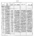
도 13-16은 9R, 10R, 9P, 및 10P 진동 브랜치에서의 회전 라인에 대한 선택된 데이터를 포함하는 표 1-4를 도시한다.1 is a simplified schematic diagram of a laser-producing plasma EUV light source according to one aspect of the present disclosure;
2 is a simplified schematic diagram of an embodiment of a laser source with a pre-pulse seed laser, a main pulse seed laser and a common amplifier.
Figure 3 shows a simplified schematic diagram of another embodiment of a laser source with a pre-pulse seed laser, a main pulse seed laser and a common amplifier.
Figure 4 shows a simplified schematic diagram of another embodiment of a laser source with a pre-pulse seed laser, a main pulse seed laser and a common amplifier.
Figure 5 shows a simplified schematic diagram of another embodiment of a laser source with a pre-pulse seed laser, a main pulse seed laser and a common amplifier.
Figure 6 shows a simplified schematic diagram of an embodiment of a wavelength tunable pre-pulse seed laser.
Figure 7 shows a simplified schematic diagram of an embodiment of a main pulse seed laser.
8 shows the output wavelength for the pre-pulse seed laser,
9 shows the output wavelength for the pre-pulse seed laser,
10 shows the output wavelength for a pre-pulse seed laser when the focal lens is used to focus the amplifier output onto the target,
Fig. 11 is a graph
12 shows the wavelength difference between the pre-pulse and the main pulse for a typical LPP system with a focal lens,
Figures 13-16 show Tables 1-4 containing selected data for the rotation lines in the 9R, 10R, 9P, and 10P vibration branches.
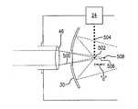
먼저, 도 1을 참조하면, 예를 들면 레이저 산출 플라즈마 EUV 광원(20)과 같은 EUV 광원의 실시예의 간략화된 개략도가 도시된다. 도 1에 도시된 바와 같이, LPP 광원(20)은 광을 생성하고 상기 광을 챔버(26)로 전달하는 시스템(22)을 포함할 수 있다. 소스(20)에 대해, 광은 시스템(22)으로부터 챔버(26)로의 하나 이상의 빔 경로를 따라 조사(照射) 영역(28)에서 각각의 타겟 액적을 조명하기 위해 이동할 수 있다. 도 1에 도시된 시스템(22)에서 사용하기에 적합할 수 있는 레이저 배치의 예시가 하기에 보다 상세히 기술된다.Referring first to Figure 1, a simplified schematic diagram of an embodiment of an EUV light source, such as, for example, a laser-producing plasma
도 1에 더 도시된 바와 같이, EUV 광원(20)은 또한 예를 들면, 조사 영역(28)에 대해 챔버(26)의 내부로 타겟 재료의 액적을 전달하는 타겟 재료 전달 시스템(24)을 포함할 수 있고, 여기서 액적은 예를 들면 제로, 하나 이상의 프리 펄스 및 그런 다음 하나 이상의 메인 펄스와 같은 하나 이상의 광 펄스와 상호작용하여, 궁극적으로 플라즈마를 산출하고 EUV 방출을 생성할 것이다. 다양한 액적 디스펜서 구성과 그의 상대적인 이점에 관한 보다 상세한 사항은 2010년 3월 10일 출원된, '레이저 산출 플라즈마 EUV 광원'이라는 제하의 미국특허출원번호 제 12/721,317, Attorney Docket No. 2008-0055-01; 2008년 6월 19일 출원된, '레이저 산출 플라즈마 EUV 광원에서의 타겟 재료 전달용 시스템 및 방법'이라는 제하의 미국특허출원번호 제 12/214,736, Attorney Docket No. 2006-0067-02; 2007년 7월 13일 출원된, '모듈레이팅된 소란파를 이용하여 산출된 액적 스트림을 가진 레이저 산출 플라즈마 EUV 광원'이라는 제하의 미국특허출원번호 제 11/827,803, Attorney Docket No. 2007-0030-01; 2006년 2월 21일 출원되고 2006년 11월 16일 공개된, '프리 펄스를 가진 레이저 산출 플라즈마 EUV 광원'이라는 제하의 미국특허출원번호 제 11/358,988, 공개번호 US2006/0255298A-1, Attorney Docket No. 2005-0085-01; 2008년 7월 29일 등록된 현재 미국특허번호 제 7,405,416이고, 2005년 2월 25일 출원된, 'EUV 플라즈마 소스 타겟 전달용 방법 및 장치'라는 제하의 미국특허출원번호 제 11/067,124, Attorney Docket No. 2004-0008-01; 2008년 5월 13일 등록된 현재 미국특허번호 제 7,372,056이고, 2005년 6월 29일 출원된, 'LPP EUV 플라즈마 소스 재료 타겟 전달 시스템'이라는 제하의 미국특허출원 제 11/174,443, Attorney Docket No. 2005-0003-01에서 볼수 있으며, 이들의 각각의 내용은 참조에 의해 본문에 통합된다.As further shown in Figure 1, the EUV
타겟 재료는 주석, 리튬, 크세논 또는 그의 조합을 구비하는 재료를 포함하지만 그에 반드시 한정되는 것은 아니다. 예를 들면, 주석, 리튬, 크세논 등과 같은 EUV 방출 원소는 액체 액적 및/또는 액체 액적에 함유된 고체 입자의 형태가 될 수 있다. 예를 들면, 주석 원소는 순수한 주석으로서, 예를 들면 SnBr4, SnBr2, SnH4와 같은 주석 화합물로서, 예를 들면 주석-갈륨 합금, 주석-인듐 합금, 주석-인듐-갈륨 합금, 또는 그의 조합과 같은 주석 합금으로서 사용될 수 있다. 사용되는 재료에 따라, 타겟 재료는 실온 또는 실온에 근접한 온도(예를 들면, 주석 합금, SnBr4), 증가된 온도(예를 들면 순수 주석), 또는 실온 미만의 온도(예를 들면, SnH4)를 포함하는 다양한 온도에서 조사 영역(28)으로 제시될 수 있고, 일부 경우에, 예를 들면 SnBr4과 같이 상대적으로 휘발성이 될 수 있다. LPP EUV 광원에서의 이들 재료의 사용에 관한 보다 상세한 사항은 그의 내용이 참조에 의해 본문에 통합된 2008년 12월 16일 등록된 현재 미국특허번호 제 7,465,946이고, 2006년 4월 17일 출원된, 'EUV 광원용 대체 연료'라는 제하의 미국특허출원번호 제 11/406,216, Attorney Docket No. 2006-0003-01에서 제공될 수 있다.The target material includes, but is not necessarily limited to, materials comprising tin, lithium, xenon, or combinations thereof. For example, EUV emission elements such as tin, lithium, xenon and the like can be in the form of solid particles contained in liquid droplets and / or liquid droplets. For example, the tin element is a pure tin, for example, SnBr4, SnBr2, a tin compound such as SnH4, for example, tin-gallium alloys, tin-indium alloy, a tin-indium-gallium alloy, or a Can be used as tin alloys such as combinations. Depending on the material used, the target material is close to the temperature to room temperature or at room temperature (for example, a tin alloy, SnBr4), an increased temperature (for example, pure tin), or, for the temperature (for example of less than room temperature, SnH4 ) may be presented in a radiation area (28) at various temperatures including the, in some cases, for example, it is a relatively volatile such as SnBr4. Further details regarding the use of these materials in LPP EUV light sources are disclosed in U.S. Patent No. 7,465,946, filed December 16, 2008, the contents of which are incorporated herein by reference, U.S. Patent Application Serial No. 11 / 406,216, entitled Alternative Fuel for EUV Light Source, Attorney Docket Nos. 2006-0003-01.
도 1을 계속 참조하면, EUV 광원(20)은 또한 예를 들면, 몰리브덴과 실리콘의 층, 및 일부 경우에 하나 이상의 고온 확산 배리어 층, 평탄화 층, 캡핑 층 및/또는 에칭 차단 층을 교대로 하면서 그레이드된 다층 코팅을 가진 장형(長形) 회전타원체(prolate spheroid)의 형태로 된(즉, 자신의 주축에 관해 회전된 타원체) 반사 표면을 가진 근-수직 입사 콜렉터 미러와 같은 광학기기(30)를 포함할 수 있다. 도 1은 광학기기(30)가 시스템(22)에 의해 생성된 광 펄스가 통과하여 조사 영역(28)에 도달하도록 허용하는 어퍼처를 가지고 형성될 수 있다는 것을 도시한다. 도시된 바와 같이, 광학 기기(30)는 예를 들면. 조사 영역(28) 내 또는 그에 인접한 제 1 초점, 및 소위 중간 영역(40)에서의 제 2 초점을 가지는 장형 회전타원체 미러가 될 수 있고, 여기서 EUV 광은 EUV 광원(20)으로부터 출력되어 예를 들면 집적회로 리소그래피 툴(도시되지 않음)과 같은 EUV 광을 활용하는 장치로 입력될 수 있다. 다른 광학 기기가 EUV 광을 활용하는 장치로의 후속하는 전달을 위해 광을 수집하여 중간 위치로 지향시키는 장형 회전타원체 미러의 위치에서 사용될 수 있고, 예를 들면, 광학기기는 자신의 주축에 관해 회전된 포물선형이거나 또는 링 형상 단면을 가진 빔을 중간 위치로 전달하도록 구성될 수 있다. 예를 들면, 그 내용이 참조에 의해 본문에 통합된 2006년 8월 16일 출원된 미국특허출원번호 제 11/505,177, EUV 광학기기, Attorney Docket No. 2006-0027-01을 참조하라.With continued reference to Figure 1, the EUV
도 1은 또한, 광원(20)이 시스템(22)과 초점 장치(46) 사이에서 빔을 신장시키고, 스티어링하고, 펄스 형성하고 및/또는 빔을 형성하기 위한 하나 이상의 광학 기기를 구비한 빔 컨디셔닝 장치(42)를 포함할 수 있다는 것을 도시한다. 광학 절연체(도시되지 않은)가 또한 시스템(22) 보호를 위해 제공될 수 있다. 빔 컨디셔닝에 관한 추가적인 상세 사항은, 예를 들면, 2006년 8월 8일 발급된 현재는 미국특허번호 제 7,087,914인, 2004년 3월 17일 출원된, 고 반복률 레이저 산출 플라즈마 EUV 광원이라는 제하의 미국특허출원번호 제 10/803,526, Attorney Docket No. 2003-0125-01; 2007년 1월 16일 발급된 현재는 미국특허번호 제 7,164,144인, 2004년 7월 27일 출원된, EUV 광원이라는 제하의 미국특허출원번호 제 10/900,839, Attorney Docket No. 2004-0044-01; 및 2009년 12월 15일 출원된, 극 자외선 광원용 빔 전달 시스템이라는 제하의 미국특허출원번호 제 12/638,092, Attorney Docket No. 2009-0029-01에서 제공되고, 이들 각각의 내용은 참조에 의해 본문에 통합된다.Figure 1 also illustrates a
소스(22)에 대해, 초점 장치(46)는 조사 위치에서의 초점에 빔을 포커싱하기 위한 하나 이상의 광학 기기를 포함할 수 있다. 예를 들면, 초점 장치는 하나 이상의 미러, 렌즈, 애크로마틱 더블릿(achromatic doublet)과 같은 애크로매틱 렌즈 또는 그의 조합을 포함할 수 있다.For the
본문에 사용된 바와 같이, "광학 기기"와 그의 파생어는 입사광을 반사하고 및/또는 전송하고 및/또는 그에 대해 동작하는 하나 이상의 컴포넌트를 포함하고(그러나 그에 한정되지는 않음), 하나 이상의 렌즈, 윈도우, 필터, 웨지, 프리즘, 그리즘(grism), 격자, 전송 파이버, 에탈론, 디퓨저, 균질화기, 검출기 및 기타 도구 컴포넌트, 어퍼처, 액시콘(axicon) 및, 다층 미러, 근-수직 입사 미러, 응시 입사 미러, 거울 반사기, 확산 반사기, 및 그의 조합을 구비하는 미러를 포함하지만, 그에 한정되지 않는다. 또한, 달리 규정되지 않는다면, 본문에 사용된 "광학기기" 및 그의 파생어 모두는 EUV 출력 광 파장, 조사 레이저 파장, 측정에 적합한 파장 또는 기타 파장에서와 같은, 하나 이상의 특정한 파장 범위(들) 내에서만 동작하는 컴포넌트 또는 그에 대한 이점에 한정되는 것을 의미한다.As used herein, "optical device" and its derivatives include (but are not limited to) one or more components that reflect and / or transmit incident light and / A window, a filter, a wedge, a prism, a grism, a grating, a transmission fiber, an etalon, a diffuser, a homogenizer, a detector and other tool components, an aperture, an axicon and a multilayer mirror, But are not limited to, mirrors having mirrors, stray incident mirrors, mirror reflectors, diffuse reflectors, and combinations thereof. In addition, unless otherwise specified, all terms used in the text, such as " optical instruments ", and derivatives thereof, may be used only within one or more specified wavelength range (s), such as at the EUV output light wavelength, the illuminating laser wavelength, Quot; is meant to be limited to the operating component or its benefits.
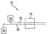
도 2는 도 1에 도시된 광원(20)에 사용하기 위한 레이저 소스(22)의 예시를 도시한다. 도 2에 도시된 바와 같이, 레이저 소스(22)는 공통 증폭기(54)를 통해 빔 경로(52)로 지향되는 출력을 산출하는 프리 펄스 시드 레이저(50) 및 공통 증폭기(54)를 통해 빔 경로(58)로 지향되는 출력을 산출하는 메인 펄스 시드 레이저(56)를 포함할 수 있다. 일부 경우, 광학 절연체(도시되지 않음)가 시드 레이저들을 보호하기 위해 증폭기와 시드 레이저들 사이에 제공될 수 있다.2 shows an example of a
도 3은 도 1에 도시된 광원(20)에서 사용하는 레이저 소스(22')의 또다른 예시를 도시한다. 도 3에 도시된 바와 같이, 레이저 소스(22')는 광학기기(60)로부터 반사된 후에 공통 빔 경로(52')로 지향되어 공통 증폭기(54)를 통과하는 출력을 산출하는 프리 펄스 시드 레이저(50) 및 광학 기기(60)를 통과하여 공통 빔 경로(58)로 지향되어 공통 증폭기(54)를 통과하는 출력을 산출하는 메인 펄스 시드 레이저(56)를 포함할 수 있다. 도 3에 도시된 배치에 대해, 광학 기기(60)는 이색성 빔 결합기, 편광 판별 빔 결합기 또는 국부 반사 빔 결합기가 될 수 있다. 상기 배치는 프리 펄스 시드 레이저 출력이 광학 기기(60)를 통해 전송되고 메인 펄스 시드 레이저 출력이 광학 기기(60)에 의해 반사되도록 변조될 수 있다는 것이 이해될 수 있다.FIG. 3 shows another example of a laser source 22 'used in the
도 4는 도 1에 도시된 광원(20)에서 사용하는 레이저 소스(22")의 또다른 예시를 도시한다. 도 4에 도시된 바와 같이, 레이저 소스(22")는 광학 기기(60)로부터의 반사후에 공통 빔 경로(52')로 지향되고 공통 증폭기(54')를 통과하는 출력을 산출하는 프리 펄스 시드 레이저(50) 및 광학 기기(60)를 통해 공통 빔 경로(52')로 지향되어 공통 증폭기(54')를 통과하는 출력을 산출하는 메인 펄스 시드 레이저(56)를 포함할 수 있다. 더 도시된 바와 같이, 증폭기(54')는 2개(또는 그 이상의)의 증폭 장치(62, 64)를 구비하고, 이들 각각은 자신의 액티브 매체와 예를 들면 펌핑 전극과 같은 여기 소스를 가진 챔버를 포함한다. 도 3에 도시된 배치에 대해, 광학 기기(60)는 이색성 빔 결합기, 편광 판별 빔 결합기 또는 국부 반사 빔 결합기가 될 수 있다. 상기 배치는 프리 펄스 시드 레이저 출력이 광학 기기(60)를 통해 전송되고 메인 펄스 시드 레이저 출력이 광학 기기(60)에 의해 반사되도록 변조될 수 있다는 것이 이해될 수 있다.4 shows another example of a
도 5는 도 1에 도시된 광원(20)에서 사용하는 광원(22"')의 또다른 예시를 도시한다. 도 5에 도시된 바와 같이, 레이저 소스(22"')는 2개(또는 그 이상의)의 증폭 장치(62', 64')를 구비한 증폭기(54")를 포함하고, 이들 각각은 자신의 액티브 매체와 예를 들면 펌핑 전극과 같은 여기 소스를 가진다. 더 도시된 바와 같이, 광학 기기(60')로부터의 반사후에 공통 빔 경로(58')로 지향되고 공통 증폭장치(64')를 통과하는 출력을 산출하는 프리 펄스 시드 레이저(50)가 제공될 수 있다. 도 5는 또한 증폭 장치(64')를 통해 광학 기기(60')를 통과하여 공통 빔 경로(58')로 지향되어 공통 증폭기(54')를 통과하는 출력을 산출하는 메인 펄스 시드 레이저(56)가 제공되는 것을 도시한다. 도 3에 도시된 배치에 대해, 광학 기기(60')는 이색성 빔 결합기, 편광 판별 빔 결합기 또는 국부 반사 빔 결합기가 될 수 있다. 상기 배치는 프리 펄스 시드 레이저 출력이 광학 기기(60')를 통해 전송되고 메인 펄스 시드 레이저 출력이 광학 기기(60)'에 의해 반사되도록 변조될 수 있다는 것이 이해될 수 있다. 하나 이상의 증폭 장치가 광학 기기(60')와 메인 펄스 시드 레이저(56) 사이에 배치될 수 있고 및/또는 하나 이상의 공유 증폭 장치가 프리 펄스 시드 레이저 출력과 증폭 장치(62')의 출력 모두를 증폭시키기 위해 공통 빔 경로(58') 상에 배치될 수 있다는 것이 더 이해될 수 있다.5 shows another example of a
도 6은 파장 조정가능한 프리 펄스 시드 레이저(50)의 실시예의 간략화된 개략도를 도시한다. 도시된 바와 같이, 프리 펄스 시드 레이저(50)는 격자(70), 출력 커플러(72), 미러(74a, 74b) 및 빔 경로(76)에 의해 정의된 광학 캐비티를 포함할 수 있다. 더 도시된 바와 같이, 빔 경로(76)는 액티브 매체(78)를 통과할 수 있다. 상기 배치에 대해, 출력 커플러는 국부 반사 광학기기가 될 수 있고, 격자(70)는 입사 빔에 대해 리트로(Littrow) 배치로 위치된 브레이징 에셀 격자(eschelle grating)가 될 수 있다. 프리 펄스 시드 레이저(50)에 대해, 액추에이터(80)가 격자(70)를 회전시키고 프리 펄스 시드 레이저 출력의 중심 파장을 변경시키기위해 제공될 수 있다. 예를 들면, 액추에이터는 스텝퍼 모터, 압전 엘리먼트/스택 또는 컴비네이션 스텝퍼 모터/압전기기를 포함할 수 있다. 기타 액추에이터 설계가 가능하다. 다른 배치는 프리즘/미러 배치, 캐비티 내부의 에탈론 또는 격자/미러 조합과 같은 리트로 배치에서의 격자에 대해 대체될 수 있다.FIG. 6 shows a simplified schematic diagram of an embodiment of a wavelength tunable
도 6은 프리 펄스 시드 레이저 출력 빔의 진단 부분을 검출기(82)로 지향시키기 위해 국부 반사 빔 스플리터 또는 픽오프 미러와 같은 광학기기(81)가 제공될 수 있다는 것을 더 도시한다. 검출기(82)는, 액추에이터(80)를 구동시키기 위한 제어 신호를 생성하는 제어 회로(84)로 중심 파장을 나타내는 신호를 출력할 수 있다. 도 6은 음향-광 변조(AOM) 스위치와 같은 스위치(86)가 광학 캐비티의 품질(Q)을 제어하고 20-150kHz의 범위에서의 펄스 반복률에서 펄스 레이저 출력을 제공하도록 제공될 수 있다는 것을 더 도시한다.6 further shows that an
하나의 설정에서, 프리 펄스 시드 레이저(50)는 무선 주파수 방전에 의해 펌핑된 예를 들면, 0.05-0.2 atm과 같은 대기속보다 낮은 압력에서의 CO2를 포함하는 기밀 가스를 가진 CO2레이저가 될 수 있다. 이러한 배치로, 격자는 표 1-4에 도시된 회전 라인 중 하나로 프리 펄스 시드 레이저(50)를 조정하도록 회전될 수 있다.In one configuration, the
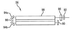
도 6에 도시된 조정가능한 시드 레이저 실시예는 또한 도 2-5에 도시된 배치에서 메인 펄스 시드 레이저(56)로서 사용될 수 있거나, 또는 도 7에 도시된 보다 간략화된 레이저(56)가 사용될 수 있다. 도시된 바와 같이, 메인 펄스 시드 레이저(56)는 완전 반사 후방 미러(90), 출력 커플러(92), 미러(94a, 94b) 및 빔 경로(96)에 의해 정의된 광학 캐비티를 포함할 수 있다. 더 도시된 바와 같이, 빔 경로(96)는 액티브 매체(98)를 통과할 수 있다. 이러한 배치를 위해, 출력 커플러(92)는 국부 반사 광학기기가 될 수 있다. 도 7은 음향-광 변조(AOM) 스위치와 같은 스위치(96)가 광학 캐비티의 품질(Q)을 제어하고 20-150kHz의 범위에서의 펄스 반복률에서 펄스 레이저 출력을 제공하도록 배치될 수 있다는 것을 더 도시한다.The adjustable seed laser embodiment shown in Fig. 6 may also be used as the main
하나의 설정에서, 메인 펄스 시드 레이저(56)는 무선 주파수 방전에 의해 펌핑된 예를 들면, 0.05-0.2 atm과 같은 대기속보다 낮은(sub-atmospheric) 압력에서의 CO2를 포함하는 기밀 가스를 가진 CO2레이저가 될 수 있다. 이러한 배치로, 메인 펄스 시드 레이저는 파장 10.5910352(표 4를 참조)을 가진 10P(20) 라인과 같은 주요한(dominant) 라인 중 하나로 자가조정될 수 있다. 일부 예시에서, 액추에이터(도시되지 않음)가 모드-호핑을 방지하도록 후방 미러(90)를 이동시키기 위해 제공될 수 있다.In one configuration, the main
다시 도 2-5를 참조하면, 각각의 배치는 하나 이상의 증폭 장치(54, 62, 64, 62', 64')를 가진 증폭기(54. 54', 54")를 포함하는 것을 볼 수 있다. 프리 펄스 시드 레이저(50)와 메인 펄스 시드 레이저(56)가 상술한 CO2를 포함하는 액티브 매체를 포함하는 경우에 대해, 증폭 장치(54, 62, 64, 62', 64')로서 사용하기 위한 적절한 레이저는 DC 또는 RF 여기에 의해 펌핑되는 CO2 가스를 함유한 액티브 매체를 포함할 수 있다. 하나의 특정한 구현에서, 증폭기는 약 10-25 미터의 총 이득 길이를 가지고 예를 들면 10kW 이상의 상대적으로 고 파워에서 동시에 동작하는 3개 또는 4개와 같은 복수의, 축방향 흐름의 RF 펌핑된(연속한 또는 펄스 변조를 하는) CO2 증폭 장치를 포함할 수 있다. 파이버, 로드, 슬랩, 또는 디스크 형상의 액티브 매체를 가지는 다른 유형의 증폭 장치가 사용될 수 있다. 일부 경우에, 고체 액티브 매체가 채용될 수 있다.Referring again to Figures 2-5, it can be seen that each arrangement includes
도 8은 프리 펄스 시드 레이저에 대한 출력 파장


표 1-4(도 13-16에 도시된)는 선택된 CO2 회전 라인에 대해 추정된 소 신호 이득 계수값, g0을 나타낸다. 보다 특정하여, 표 1-4는 일반적인 CO2 레이저용 각각의 회전 라인에 대한 공개된 출력 파워와 함께, 9R 진동 브랜치, 10R 진동 브랜치, 9P 진동 브랜치 및 10P 진동 브랜치 각각에서의 회전 라인에 대한 파장을 보여준다. 이러한 데이터로부터, 10P(20)와 같은 공지된 증폭기 소 신호 이득(SSG)을 가진 파장의 파워 P10P(20)에 대해, 파워 P가 각각의 회전 라인에 대해 연산될 수 있다(예를 들면 표 1; 세로 열 4를 참조하라). 표 1은 또한 선택된 라인(이러한 경우(10P20)라인)에 대한 소 신호 이득이 하기와 같은, Rigrod 분석을 이용하여 연산될 수 있다(세로열 5)는 것을 보여준다:Table 1-4 (shown in Figures 13-16) shows the estimated small signal gain factor, g0 , for the selected CO2 rotation line. More specifically, Table 1-4 shows the wavelengths for the rotation lines in the 9R vibration branch, the 10R vibration branch, the 9P vibration branch, and the 10P vibration branch, respectively, together with the disclosed output power for each rotation line for a typical CO2 laser Lt; / RTI > From this data, for a power P10P(20) of a wavelength having a known amplifier small signal gain (SSG) such as10P(20) , a power P can be computed for each

여기서, Lcavity는 광학 캐비티 길이이고, R1 및 R2는 일반적인 CO2 레이저에 대한 미러 반사도이다. 특히, I=P/A(여기서, I는 강도이고 A는 출력 빔의 면적)를 유의하면, 표 1-4의 세로열 5에 표시된 상대 이득(즉, Iout,10P20에 대한 Iout,selectedline의 비율)은 하기의 상대 파워(표 1-4의 세로열 4)로부터 연산될 수 있다:
Isat,selectedline/Isat,10P20이 약 1이라면, 상기 표현은, g0,10P20이 공지된 것으로 가정되기 때문에, 그런다음 각각의 라인에 대해 g0,selectedline을 찾기 위해 해답을 얻을 수 있다. 소 신호 이득 계수, g0를 가지고, 증폭기 이득, G는 하기의 표현을 이용하여 연산될 수 있다:Isat,selected If theline / Isat, 10P20 is approximately 1, wherein the representation, g0, 10P20 is assumed to be because the well-known, such g0, and then for each lineselected You can get the answer to find theline . With a small signal gain factor, g0 , the amplifier gain, G, can be calculated using the following expression:

여기서, L은 증폭기 이득 매체의 길이이다. 상기 분석은 상이한 유형의 CO2 레이저에 대한 소 신호 이득 대역의 전체 형상이 거의 동일하다는 것을 가정한다. 대안의 접근 방식은 사용되고 있는 특정한 증폭기에서의 특정한 관심 라인에 대해 소 신호 이득 계수, g0을 측정하는 것을 포함할 수 있다.Where L is the length of the amplifier gain medium. This analysis assumes that the overall shape of the small signal gain bands for different types of CO2 lasers is approximately the same. An alternative approach may include measuring the small signal gain factor, go , for a particular line of interest in the particular amplifier being used.
도 8을 계속해서 참조하면, 다음 절차의 단계는 소스 재료 타겟(예를 들면 액적)에서의 원하는 프리 펄스 에너지를 판정하는 단계를 포함할 수 있다는 것을 이해할 수 있다(상자 202). 예를 들면, 약 10-100㎛의 범위에서의 직경을 가지는 주석 액적에 대해, 타겟에서의 원하는 메인 펄스 에너지는 약 300-700mJ의 범위에 있을 수 있고, 타겟에서의 원하는 프리 펄스 에너지는 약 6-12mJ의 범위에 있을 수 있다. 이들 원하는 에너지들은 타겟 재료 액적의 크기 및 대응하는 프리 펄스 및 메인 펄스 초점 크기, 프리 펄스로 액적을 타겟팅할 때 달성가능한 정확도의 레벨, 프리 펄스와 메인 펄스 사이의 지연, 프리 펄스 및 메인 펄스 펄스 듀레이션, 프리 펄스 파장, 원하는 레벨의 EUV 출력 에너지, 원하는 변환 효율(CE), 및 프리 펄스(부풀어진(puffed)) 플라즈마의 원하는 반사도와 같은 다양한 팩터에 대해 조정될 수 있다는 것이 이해될 수 있다.Continuing with FIG. 8, it will be appreciated that the next procedural step may include determining the desired pre-pulse energy in the source material target (e.g., droplet) (box 202). For example, for a tin droplet having a diameter in the range of about 10-100 占 퐉, the desired main pulse energy at the target can be in the range of about 300-700 mJ, and the desired pre-pulse energy at the target is about 6 -12 mJ. ≪ / RTI > These desired energies include the magnitude of the target material droplet and the corresponding pre-pulse and main pulse focus size, the level of accuracy achievable when targeting the droplet as a pre-pulse, the delay between the pre-pulse and the main pulse, , The pre-pulse wavelength, the desired level of EUV output energy, the desired conversion efficiency (CE), and the desired reflectivity of the pre-pulse (puffed) plasma.
다음으로, 도 8에 도시된 바와 같이(상자 204), 채용될 특정 유형의 프리 펄스 시드 레이저에 대한 동작 범위를 판정하는 것이 적절할 수 있다. 특히, 이는 레이저 컴포넌트 제한 및/또는 안정적인 레이저 동작을 고려한 후에 달성될 수 있는 출력 펄스 에너지의 범위를 판정하는 것을 수반할 수 있다. 증가 시간, 듀레이션 등과 같은 레이저 펄스 파라미터, 비용, 복잡도, 효율, 신뢰도를 포함하는 다수의 팩터가 프리 펄스 시드 레이저의 유형에 영향을 줄 수 있다는 것이 이해될 것이다. 일부 구성에서, 도 6을 참조하여 상술한 프리 펄스 시드 레이저(50)는 약 0.01-1000μJ의 펄스 에너지 출력 동작 범위를 가질 수 있다. 일부 배치는 약 0.1-100μJ의 펄스 에너지 출력 범위에 더 제한될 수 있다. 사용되는 시드 레이저의 유형에 따라, 시드 레이저 펄스 에너지 출력에 대해 다른 제한이 있을 수 있다.Next, it may be appropriate to determine the operating range for the particular type of pre-pulse seed laser to be employed, as shown in Fig. 8 (box 204). In particular, this may involve determining the range of output pulse energies that can be achieved after considering laser component limitation and / or stable laser operation. It will be appreciated that a number of factors may affect the type of pre-pulse seed laser, including laser pulse parameters such as increase time, duration, etc., cost, complexity, efficiency, In some configurations, the
상자(208)-(216)는 증폭기(들)가 메인 펄스 증폭을 위한 최대 에너지 추출에 최적화되고 프리 펄스 동작 범위가 수립된다면 프리 펄스 파장,


프리 펄스 레이저용 출력 펄스 에너지 동작 범위와 비교된다(결정 상자 212). 선택된 프리 펄스 시드 출력 에너지 EPP-SEED가 출력 펄스 에너지 동작 범위 내에 있다면(상자 214), 선택된 프리 펄스

하기의 예시는 4개의 증폭 장치를 가진 증폭기에 대해 상술한 프로시저를 도시한다. 일부 배치에서, 증폭 장치는 이득 길이, 가스 조성, 가스 압력 등에서 상이할 수 있으며, 따라서 상이한 소 신호 이득 계수, g0 및 포화 에너지(saturation energy), Esat를 가질 수 있다. 예를 들면, 본문에 그 내용이 참조에 의해 통합된, 2006년 6월 14일 출원된, 'EUV 광원용 구동 레이저'라는 제하의 미국특허출원번호 제 11/452,558, Attorney Docket 번호 2006-0001-01을 참조하라. 이러한 예시에 대해, 10P(20) 라인에 대응하는 10.5910352㎛의 메인 펄스 파장,


또한, 본 예시에 대해, 10mJ의 타겟 에너지에서의 프리 펄스가 규정되고, 0.01-1000μJ의 펄스 에너지 출력 동작 범위가 설정된다. 도 8에 도시된 프로시저를 이용하여, 라인 9R(18)에 대응하는 9.2824434 ㎛의 최초 프리 펄스


도 9는 프리 펄스 시드 레이저에 대한 출력 파장

도 9의 프로시저는 타겟에서의 원하는 메인 펄스 파장(상자 300) 및 메인 펄스 파장,


도 9를 계속해서 참조하면, 다음 절차의 단계는 소스 재료 타겟(예를 들면 액적)에서의 원하는 프리 펄스 에너지를 판정하는 단계(상자 306)를 포함할 수 있다는 것을 이해할 수 있다. 예를 들면, 약 10-100㎛의 범위에서의 직경을 가지는 주석 액적에 대해, 타겟에서의 원하는 메인 펄스 에너지는 약 300-700mJ의 범위에 있을 수 있고, 타겟에서의 원하는 프리 펄스 에너지는 약 6-12mJ의 범위에 있을 수 있다. 상술한 바와 같이, 원하는 타겟 에너지들은 다양한 팩터에 대해 조정될 수 있다.With continuing reference to FIG. 9, it will be appreciated that the next procedural step may include determining (step 306) the desired pre-pulse energy at the source material target (e.g., droplet). For example, for a tin droplet having a diameter in the range of about 10-100 占 퐉, the desired main pulse energy at the target can be in the range of about 300-700 mJ, and the desired pre-pulse energy at the target is about 6 -12 mJ. ≪ / RTI > As noted above, desired target energies can be adjusted for various factors.
다음으로, 도 9에 도시된 바와 같이(상자 308), 메인 펄스 레이저 출력 펄스 에너지에 대한 프리 펄스 레이저 출력 펄스 에너지의 수용가능한 비율을 판정하는 것이 적절할 수 있다. 일부 경우, 수용가능한 비율에 대한 엄수(adherence)는 프리 펄스 시드 출력이 메인 펄스 파장의 증폭기 이득을 실질적으로 격감시키지 않는다는 것을 제공할 수 있다.Next, as shown in FIG. 9 (box 308), it may be appropriate to determine an acceptable ratio of the pre-pulse laser output pulse energy to the main pulse laser output pulse energy. In some cases, adherence to an acceptable rate can provide that the pre-pulse seed output does not substantially reduce the amplifier gain of the main pulse wavelength.
예를 들면, 메인 펄스 레이저 출력 펄스 에너지에 대한 프리 펄스 레이저 출력 펄스 에너지의 수용가능한 비율은 EPP/EMP < 1000이고, 일부 경우에, 메인 펄스 레이저 출력 펄스 에너지에 대한 프리 펄스 레이저 출력 펄스 에너지의 수용가능한 비율은 EPP/EMP < 10와 같이 보다 엄격하게 정의될 수 있다. 또한, 이들 비율에 대해, 프리 펄스 증폭기 출력 펄스 에너지 EPP-AMPED가 10배의 크기까지(an order of magnitude), 즉, EMP-AMPED > 10 x EPP-AMPED 까지 메인 펄스 증폭기 출력 펄스 에너지 EMP-AMPED 보다 더 작은 것이 고려된다.For example, an acceptable ratio of the pre-pulse laser output pulse energy to the main pulse laser output pulse energy is EPP / EMP < 1000 and, in some cases, the pre-pulse laser output pulse energy Can be more strictly defined, such as EPP / EMP < 10. Also, for these ratios, the main pulse amplifier output pulse energy EPP-AMPED up to an order of magnitude, i.e., EMP-AMPED > 10 x EPP-AMPED , EMP-AMPED .
도 9의 프로시저를 계속해서 참조하면, 상자(310)-(320)는 증폭기 이득 대역 및 메인 펄스 레이저 출력 펄스 에너지에 대한 프리 펄스 레이저 출력 에너지의 수용가능한 비율이 수립된다면, 프리 펄스 파장,


프리 펄스 시드 출력 펄스 에너지가 연산되고(상자 314), 메인 펄스 시드 에너지가 연산되면(상자 304), 이들의 비율이 결정되고, 메인 펄스 레이저 출력 펄스 에너지에 대한 프리 펄스 레이저 출력 펄스 에너지의 수용가능한 비율과 비교된다(상자 316).When the pre-pulse seed output pulse energy is computed (box 314) and the main pulse seed energy is computed (box 304), the proportions thereof are determined, and the available pulsed laser output pulse energy for the main pulse laser output pulse energy (Box 316).
상기 비율이 수용가능한 범위 내에 있다면(상자 318), 선택된 프리 펄스

도 9의 프로시저에 대한 대안으로서, 최소의 프리 펄스 시드 에너지가 식별되어 메인 펄스 이득 격감이 수용가능하도록 한다. 최소 프리 펄스 시드 에너지는 그런다음 도 9의 프로시저에서 메인 펄스 레이저 출력 펄스 에너지에 대한 프리 펄스 레이저 출력 펄스 에너지의 수용가능한 비율에 대해 대체될 수 있다.As an alternative to the procedure of FIG. 9, a minimum pre-pulse seed energy is identified to allow the main pulse gain reduction to be acceptable. The minimum pre-pulse seed energy may then be substituted for the acceptable ratio of the pre-pulse laser output pulse energy to the main pulse laser output pulse energy in the procedure of FIG.
도 8, 9 또는 그의 조합과 함께 고려될 수 있는 또다른 팩터는 프리 펄스 파장과 메인 펄스 파장이 공통 상부 에너지 레벨을 공유할 때 발생하는 이득 소멸(gain depletion)에 대한 효과이다. 이러한 것이 발생할 때, 프리 펄스 증폭에 기인한 메인 펄스 이득 소멸은 일반적으로 프리 펄스 파장과 메인 펄스 파장이 공통 상부 에너지 레벨을 공유하지 않을 때보다 더 높다. CO2 레이저에 대해, 9R 진동 브랜치에서의 모든 회전 라인 및 10R 진동 브랜치에서의 모든 회전 라인은 공통 상부 레벨을 공유한다. 또한 9P 진동 브랜치에서의 모든 회전 라인 및 10P 진동 브랜치에서의 모든 회전 라인은 공통 상부 레벨을 공유한다.Another factor that can be considered with Figures 8, 9, or a combination thereof is the effect on gain depletion that occurs when the pre-pulse wavelength and the main pulse wavelength share a common upper energy level. When this happens, the main pulse gain extinction due to pre-pulse amplification is generally higher than when the pre-pulse wavelength and the main pulse wavelength do not share a common upper energy level. For CO2 lasers, all the rotation lines in the 9R vibration branch and all the rotation lines in the 10R vibration branch share a common upper level. Also, all of the rotation lines in the 9P vibration branch and all of the rotation lines in the 10P vibration branch share a common upper level.
메인 펄스 및 프리 펄스 파장 선택시 고려될 수 있는 또다른 팩터는 이색성 스플리터 및 결합기의 사용이다. 이에 관련하여, 이색성 광학기기에 의해 > 90%의 결합 효율을 획득하기 위해 약 0.14㎛와 같은 최소 파장 차이가 메인 펄스와 프리 펄스 파장 사이에서 요구될 수 있다.Another factor that can be considered in selecting the main and pre-pulse wavelengths is the use of dichroic splitter and combiner. In this regard, a minimum wavelength difference of about 0.14 [mu] m may be required between the main pulse and the pre-pulse wavelength in order to achieve a coupling efficiency of > 90% by the dichroic optics.
도 10은 예를 들면 액적과 같은 타겟 상에 증폭기 출력을 포커싱하기 위해 초점 렌즈가 사용될 때 프리 펄스 시드 레이저에 대한 출력 파장


도 10의 프로시저는 메인 펄스 파장,


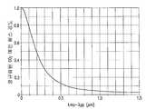
수용가능한 간격 "d"로부터 벗어난, EUV 출력은 소스 재료 상의 메인 펄스 강도의 감소에 기인하여 감소될 수 있다. 도 12는 96mm의 선명한 어퍼처(clear aperture) 및 300mm의 초점 거리를 가진 ZnSe 초점 렌즈를 구비한 일반적인 LPP 시스템에 대해 프리 펄스와 메인 펄스 사이의 파장 차이,


다시 도 10을 참조하면, 색수차에 기인한 메인 펄스와 프리 펄스 사이의 수용가능한 초점 간격, dacceptable이 결정되면, 상자(404)-(412)는 프리 펄스 파장,


당업자는, 상술한 실시예들이 본 출원에 의해 폭넓게 사용되는 제재의 범위를 한정할 의도를 가지지 않고, 단순히 예시를 의도한다는 것을 이해해야한다. 당업자는 본문에 개시된 제재의 범위 내에서 개시된 실시예들에 대해 추가, 삭제 및 변형이 이루어질 수 있다는 것을 이해해야 한다. 첨부된 청구범위는 개시된 실시예들 뿐만 아니라 이러한 등가물과 당업자들에게 명확한 기타 변형을 포함하는 범위 및 의미를 의도한다. 명확하게 기술되지 않는다면, 단수형으로 된 하기의 청구범위에서의 구성요소에 대한 참조 및 관사 "a"에 의해 선행된 구성요소에 대한 참조는 "하나 이상의" 상기 구성요소(들)을 의미하도록 의도된다. 본문에 제공된 개시물 중 어떤 것도 청구범위에 명확하게 인용된 것과는 관계없이 공공의 것으로 헌정된 것을 의도하지 않는다.Skilled artisans will appreciate that the above-described embodiments are not intended to limit the scope of the sanction widely used by the present application, but merely as exemplifications. Those skilled in the art will recognize that additions, deletions and modifications can be made to the embodiments disclosed within the scope of the disclosure herein. The appended claims are intended to cover the scope and meaning of the disclosed embodiments, as well as other equivalents and other modifications that are obvious to those skilled in the art. Unless specifically stated, references to components in the following claims that are singular and references to components preceded by article "a" are intended to mean "one or more" said component (s) . None of the disclosure provided herein is intended to be construed as constituting a public matter, nor is it explicitly recited in the claims.
Claims (20)
Translated fromKorean


파장

파장

상기 광학 증폭기를 통과해 공통 경로 상으로 상기 프리 펄스 출력과 상기 메인 펄스 출력을 지향시키는 빔 결합기를 포함하고,
상기 튜닝 모듈에 의한 조정은:
(a) 상기 메인 펄스 시드 레이저를 위한 파장

(b) 상기 선택 후에, 프리 펄스 파장들 중 하나를 이용하여 계산된 프리 펄스 시드 출력 펄스 에너지가, (i) 상기 계산된 프리 펄스 시드 출력 펄스 에너지가 상기 프리 펄스 시드 레이저를 위한 동작 출력 펄스 에너지 범위 내에 있는 제1 조건, 및 (ii) 메인 펄스 레이저 출력 펄스 에너지에 대한 상기 계산된 프리 펄스 시드 출력 펄스 에너지의 비율이 미리정해진 범위 내에 있는 제2 조건 중 적어도 한 조건을 충족시키도록, 시행 착오 접근 방식을 이용하여 프리 펄스 파장들을 반복적으로 분석하며,
(c) 상기 제1 조건 및 제2 조건 중 적어도 하나가 충족되는 프리 펄스 파장을

wavelength
wavelength
And a beam combiner for directing the pre-pulse output and the main pulse output on a common path through the optical amplifier,
The adjustment by the tuning module is:
(a) a wavelength for the main pulse seed laser
(b) after the selection, the pre-pulse seed output pulse energy calculated using one of the pre-pulse wavelengths is selected from the group consisting of (i) the calculated pre-pulse seed output pulse energy is an operation output pulse energy , And (ii) a second condition in which the ratio of the calculated pre-pulse seed output pulse energy to the main pulse laser output pulse energy is within a predetermined range, Approach, iteratively analyzes pre-pulse wavelengths,
(c) a pre-pulse wavelength satisfying at least one of the first condition and the second condition is


파장

파장

상기 광학 증폭기를 통과해 공통 빔 경로 상으로 상기 프리 펄스 출력과 상기 메인 펄스 출력을 지향시키는 빔 결합기를 포함하고,
상기 프리 펄스 시드 레이저는 프리 펄스 출력을 조정하기 위한 튜닝 모듈을 포함하되, 상기 튜닝 모듈에 의한 조정은:
(a) 상기 메인 펄스 시드 레이저를 위한 파장

(b) 상기 선택 후에, 프리 펄스 파장들 중 하나를 이용하여 계산된 프리 펄스 시드 출력 펄스 에너지가, (i) 상기 계산된 프리 펄스 시드 출력 펄스 에너지가 상기 프리 펄스 시드 레이저를 위한 동작 출력 펄스 에너지 범위 내에 있는 제1 조건, 및 (ii) 메인 펄스 레이저 출력 펄스 에너지에 대한 상기 계산된 프리 펄스 시드 출력 펄스 에너지의 비율이 미리정해진 범위 내에 있는 제2 조건 중 적어도 한 조건을 충족시키도록, 시행 착오 접근 방식을 이용하여 프리 펄스 파장들을 반복적으로 분석하며,
(c) 상기 제1 조건 및 제2 조건 중 적어도 하나가 충족되는 프리 펄스 파장을

wavelength
wavelength
And a beam combiner for directing the pre-pulse output and the main pulse output through the optical amplifier onto a common beam path,
Wherein the pre-pulse seed laser comprises a tuning module for adjusting a pre-pulse output, wherein the adjustment by the tuning module comprises:
(a) a wavelength for the main pulse seed laser
(b) after the selection, the pre-pulse seed output pulse energy calculated using one of the pre-pulse wavelengths is selected from the group consisting of (i) the calculated pre-pulse seed output pulse energy is an operation output pulse energy , And (ii) a second condition in which the ratio of the calculated pre-pulse seed output pulse energy to the main pulse laser output pulse energy is within a predetermined range, Approach, iteratively analyzes pre-pulse wavelengths,
(c) a pre-pulse wavelength satisfying at least one of the first condition and the second condition is


파장

파장

상기 광학 증폭기를 통과해 공통 경로 상으로 상기 프리 펄스 출력과 상기 메인 펄스 출력을 지향시키는 빔 결합기;
를 포함하고,
여기서


상기 프리 펄스 시드 레이저는 파장

(a) 상기 메인 펄스 시드 레이저를 위한 파장

(b) 상기 선택 후에, 프리 펄스 파장들 중 하나를 이용하여 계산된 프리 펄스 시드 출력 펄스 에너지가, (i) 상기 계산된 프리 펄스 시드 출력 펄스 에너지가 상기 프리 펄스 시드 레이저를 위한 동작 출력 펄스 에너지 범위 내에 있는 제1 조건, 및 (ii) 메인 펄스 레이저 출력 펄스 에너지에 대한 상기 계산된 프리 펄스 시드 출력 펄스 에너지의 비율이 미리정해진 범위 내에 있는 제2 조건 중 적어도 한 조건을 충족시키도록, 시행 착오 접근 방식을 이용하여 프리 펄스 파장들을 반복적으로 분석하며,
(c) 상기 제1 조건 및 제2 조건 중 적어도 하나가 충족되는 프리 펄스 파장을

wavelength
wavelength
A beam combiner for directing the pre-pulse output and the main pulse output on a common path through the optical amplifier;
Lt; / RTI >
here
The pre-pulse seed laser has a wavelength
(a) a wavelength for the main pulse seed laser
(b) after the selection, the pre-pulse seed output pulse energy calculated using one of the pre-pulse wavelengths is selected from the group consisting of (i) the calculated pre-pulse seed output pulse energy is an operating output pulse energy , And (ii) a second condition in which the ratio of the calculated pre-pulse seed output pulse energy to the main pulse laser output pulse energy is within a predetermined range, Approach, iteratively analyzes pre-pulse wavelengths,
(c) a pre-pulse wavelength satisfying at least one of the first condition and the second condition is


Applications Claiming Priority (5)
| Application Number | Priority Date | Filing Date | Title |
|---|---|---|---|
| US39845210P | 2010-06-24 | 2010-06-24 | |
| US61/398,452 | 2010-06-24 | ||
| US13/077,236US8654438B2 (en) | 2010-06-24 | 2011-03-31 | Master oscillator-power amplifier drive laser with pre-pulse for EUV light source |
| US13/077,236 | 2011-03-31 | ||
| PCT/US2011/037793WO2011162903A1 (en) | 2010-06-24 | 2011-05-24 | Master oscillator-power amplifier drive laser with pre-pulse for euv light source |
Publications (2)
| Publication Number | Publication Date |
|---|---|
| KR20130121809A KR20130121809A (en) | 2013-11-06 |
| KR101835561B1true KR101835561B1 (en) | 2018-03-07 |
Family
ID=45352322
Family Applications (1)
| Application Number | Title | Priority Date | Filing Date |
|---|---|---|---|
| KR1020137000713AActiveKR101835561B1 (en) | 2010-06-24 | 2011-05-24 | Master oscillatorpower amplifier drive laser with prepulse for euv light source |
Country Status (7)
| Country | Link |
|---|---|
| US (2) | US8654438B2 (en) |
| EP (1) | EP2586107A1 (en) |
| JP (1) | JP5893014B2 (en) |
| KR (1) | KR101835561B1 (en) |
| CN (1) | CN102971922B (en) |
| TW (1) | TWI535338B (en) |
| WO (1) | WO2011162903A1 (en) |
Families Citing this family (42)
| Publication number | Priority date | Publication date | Assignee | Title |
|---|---|---|---|---|
| US9091754B2 (en) | 2009-09-02 | 2015-07-28 | Trimble A.B. | Distance measurement methods and apparatus |
| US8872142B2 (en) | 2010-03-18 | 2014-10-28 | Gigaphoton Inc. | Extreme ultraviolet light generation apparatus |
| DE102013002064A1 (en)* | 2012-02-11 | 2013-08-14 | Media Lario S.R.L. | SOURCE-COLLECTOR MODULES FOR EUV LITHOGRAPHY USING A GIC MIRROR AND AN LPP SOURCE |
| US8681427B2 (en)* | 2012-05-31 | 2014-03-25 | Cymer, Inc. | System and method for separating a main pulse and a pre-pulse beam from a laser source |
| DE102012209837A1 (en) | 2012-06-12 | 2013-12-12 | Trumpf Laser- Und Systemtechnik Gmbh | EUV excitation light source with a laser beam source and a beam guiding device for manipulating the laser beam |
| JP6099241B2 (en)* | 2012-06-28 | 2017-03-22 | ギガフォトン株式会社 | Target supply device |
| US8811440B2 (en) | 2012-09-07 | 2014-08-19 | Asml Netherlands B.V. | System and method for seed laser mode stabilization |
| US10031422B2 (en) | 2012-10-26 | 2018-07-24 | Asml Netherlands B.V. | Lithographic apparatus |
| US10289006B2 (en) | 2012-12-20 | 2019-05-14 | Asml Netherlands B.V. | Beam delivery for EUV lithography |
| JPWO2014119198A1 (en)* | 2013-01-31 | 2017-01-26 | ギガフォトン株式会社 | Laser apparatus and extreme ultraviolet light generator |
| US8872143B2 (en) | 2013-03-14 | 2014-10-28 | Asml Netherlands B.V. | Target for laser produced plasma extreme ultraviolet light source |
| US8791440B1 (en) | 2013-03-14 | 2014-07-29 | Asml Netherlands B.V. | Target for extreme ultraviolet light source |
| JP6151054B2 (en)* | 2013-03-22 | 2017-06-21 | ギガフォトン株式会社 | Laser apparatus and extreme ultraviolet light generator |
| CN104283098B (en)* | 2013-07-11 | 2017-05-10 | 中国科学院大连化学物理研究所 | Transverse flow gas mechanical Q switched pulse laser |
| EP3045021B1 (en) | 2013-09-12 | 2017-11-08 | TRUMPF Lasersystems for Semiconductor Manufacturing GmbH | Beam guiding apparatus and euv beam generating device comprising a superposition apparatus |
| EP3045022B1 (en) | 2013-09-12 | 2017-11-08 | TRUMPF Lasersystems for Semiconductor Manufacturing GmbH | Beam guiding apparatus and euv beam generating device comprising a superposition apparatus |
| US9338870B2 (en) | 2013-12-30 | 2016-05-10 | Asml Netherlands B.V. | Extreme ultraviolet light source |
| US9232623B2 (en) | 2014-01-22 | 2016-01-05 | Asml Netherlands B.V. | Extreme ultraviolet light source |
| US9209595B2 (en)* | 2014-01-31 | 2015-12-08 | Asml Netherlands B.V. | Catalytic conversion of an optical amplifier gas medium |
| US9357625B2 (en) | 2014-07-07 | 2016-05-31 | Asml Netherlands B.V. | Extreme ultraviolet light source |
| KR101909842B1 (en) | 2014-07-11 | 2018-10-18 | 트럼프 레이저시스템즈 포 세미컨덕터 매뉴팩처링 게엠베하 | Driver laser arrangement, euv radiation generation apparatus and method for amplifying pulsed laser radiation |
| JPWO2016027346A1 (en)* | 2014-08-21 | 2017-06-01 | 公益財団法人レーザー技術総合研究所 | Extreme ultraviolet light generation system and extreme ultraviolet light generation method |
| WO2016131583A1 (en)* | 2015-02-19 | 2016-08-25 | Asml Netherlands B.V. | Radiation source |
| US9832855B2 (en) | 2015-10-01 | 2017-11-28 | Asml Netherlands B.V. | Optical isolation module |
| JP6688966B2 (en)* | 2015-07-27 | 2020-04-28 | パナソニックIpマネジメント株式会社 | Particle detection sensor |
| US9820368B2 (en) | 2015-08-12 | 2017-11-14 | Asml Netherlands B.V. | Target expansion rate control in an extreme ultraviolet light source |
| TWI739755B (en)* | 2015-08-12 | 2021-09-21 | 荷蘭商Asml荷蘭公司 | Target expansion rate control in an extreme ultraviolet light source |
| US9536631B1 (en)* | 2015-11-19 | 2017-01-03 | Asml Netherlands B.V. | Systems and methods to avoid instability conditions in a source plasma chamber |
| EP3381244B1 (en) | 2015-11-27 | 2022-06-08 | TRUMPF Lasersystems for Semiconductor Manufacturing GmbH | Driver laser arrangement, euv radiation generating device and method for amplifying laser pulses |
| JP6714397B2 (en)* | 2016-03-08 | 2020-06-24 | 株式会社サタケ | Piezoelectric valve, driving method of the piezoelectric valve, and optical granular material sorting machine including a blowing means using the piezoelectric valve |
| US20170311429A1 (en) | 2016-04-25 | 2017-10-26 | Asml Netherlands B.V. | Reducing the effect of plasma on an object in an extreme ultraviolet light source |
| US10036963B2 (en)* | 2016-09-12 | 2018-07-31 | Cymer, Llc | Estimating a gain relationship of an optical source |
| US10048199B1 (en)* | 2017-03-20 | 2018-08-14 | Asml Netherlands B.V. | Metrology system for an extreme ultraviolet light source |
| US10299361B2 (en)* | 2017-03-24 | 2019-05-21 | Asml Netherlands B.V. | Optical pulse generation for an extreme ultraviolet light source |
| US10524345B2 (en)* | 2017-04-28 | 2019-12-31 | Taiwan Semiconductor Manufacturing Co., Ltd. | Residual gain monitoring and reduction for EUV drive laser |
| US10925142B2 (en)* | 2018-07-31 | 2021-02-16 | Taiwan Semiconductor Manufacturing Co., Ltd. | EUV radiation source for lithography exposure process |
| US12078934B2 (en)* | 2018-09-25 | 2024-09-03 | Asml Netherlands B.V. | Laser system for target metrology and alteration in an EUV light source |
| EP3997518A1 (en)* | 2019-07-11 | 2022-05-18 | ASML Netherlands B.V. | A measurement system for use with a light amplification cavity |
| KR20210152703A (en)* | 2020-06-09 | 2021-12-16 | 삼성전자주식회사 | Semiconductor manufacturing apparatus and operating method thereof |
| CN113296368B (en)* | 2021-04-27 | 2023-01-31 | 广东省智能机器人研究院 | Extreme ultraviolet radiation control method and device, electronic equipment and extreme ultraviolet radiation system |
| DE102022205360A1 (en)* | 2022-05-30 | 2023-11-30 | Trumpf Lasersystems For Semiconductor Manufacturing Gmbh | EUV radiation generation after laser beam rotation |
| WO2025201796A1 (en)* | 2024-03-28 | 2025-10-02 | Stichting Nederlandse Wetenschappelijk Onderzoek Instituten | System and method for irradiating a fuel target |
Citations (2)
| Publication number | Priority date | Publication date | Assignee | Title |
|---|---|---|---|---|
| US20060146906A1 (en)* | 2004-02-18 | 2006-07-06 | Cymer, Inc. | LLP EUV drive laser |
| US20090161201A1 (en)* | 2007-12-20 | 2009-06-25 | Cymer, Inc. | Drive laser for EUV light source |
Family Cites Families (46)
| Publication number | Priority date | Publication date | Assignee | Title |
|---|---|---|---|---|
| US4107536A (en) | 1974-08-21 | 1978-08-15 | General Electric Company | Method for isotope-selective vibrational excitation of a gaseous compound of an isotope using multiple wavelengths |
| FR2331371A1 (en) | 1975-11-12 | 1977-06-10 | Commissariat Energie Atomique | METHOD AND DEVICE FOR EXCITATION AND SELECTIVE DISSOCIATION BY ABSORPTION OF LASER LIGHT AND APPLICATION TO ISOTOPIC ENRICHMENT |
| FR2331900A1 (en) | 1975-11-13 | 1977-06-10 | Commissariat Energie Atomique | WAVELENGTH SELECTIVE SWITCH DEVICE |
| JPH098387A (en)* | 1995-06-15 | 1997-01-10 | Toshiba Corp | Laser amplifier |
| US6567450B2 (en) | 1999-12-10 | 2003-05-20 | Cymer, Inc. | Very narrow band, two chamber, high rep rate gas discharge laser system |
| US6625191B2 (en) | 1999-12-10 | 2003-09-23 | Cymer, Inc. | Very narrow band, two chamber, high rep rate gas discharge laser system |
| US6549551B2 (en) | 1999-09-27 | 2003-04-15 | Cymer, Inc. | Injection seeded laser with precise timing control |
| US6693939B2 (en) | 2001-01-29 | 2004-02-17 | Cymer, Inc. | Laser lithography light source with beam delivery |
| US7897947B2 (en) | 2007-07-13 | 2011-03-01 | Cymer, Inc. | Laser produced plasma EUV light source having a droplet stream produced using a modulated disturbance wave |
| US6928093B2 (en) | 2002-05-07 | 2005-08-09 | Cymer, Inc. | Long delay and high TIS pulse stretcher |
| US7843632B2 (en) | 2006-08-16 | 2010-11-30 | Cymer, Inc. | EUV optics |
| US7476886B2 (en) | 2006-08-25 | 2009-01-13 | Cymer, Inc. | Source material collection unit for a laser produced plasma EUV light source |
| US7372056B2 (en) | 2005-06-29 | 2008-05-13 | Cymer, Inc. | LPP EUV plasma source material target delivery system |
| US7518787B2 (en) | 2006-06-14 | 2009-04-14 | Cymer, Inc. | Drive laser for EUV light source |
| US7928416B2 (en) | 2006-12-22 | 2011-04-19 | Cymer, Inc. | Laser produced plasma EUV light source |
| US7415056B2 (en) | 2006-03-31 | 2008-08-19 | Cymer, Inc. | Confocal pulse stretcher |
| US7491954B2 (en) | 2006-10-13 | 2009-02-17 | Cymer, Inc. | Drive laser delivery systems for EUV light source |
| US7405416B2 (en) | 2005-02-25 | 2008-07-29 | Cymer, Inc. | Method and apparatus for EUV plasma source target delivery |
| US7465946B2 (en) | 2004-03-10 | 2008-12-16 | Cymer, Inc. | Alternative fuels for EUV light source |
| US7598509B2 (en) | 2004-11-01 | 2009-10-06 | Cymer, Inc. | Laser produced plasma EUV light source |
| US20050259709A1 (en) | 2002-05-07 | 2005-11-24 | Cymer, Inc. | Systems and methods for implementing an interaction between a laser shaped as a line beam and a film deposited on a substrate |
| US7378673B2 (en) | 2005-02-25 | 2008-05-27 | Cymer, Inc. | Source material dispenser for EUV light source |
| US20060255298A1 (en) | 2005-02-25 | 2006-11-16 | Cymer, Inc. | Laser produced plasma EUV light source with pre-pulse |
| US7439530B2 (en) | 2005-06-29 | 2008-10-21 | Cymer, Inc. | LPP EUV light source drive laser system |
| US6784399B2 (en) | 2001-05-09 | 2004-08-31 | Electro Scientific Industries, Inc. | Micromachining with high-energy, intra-cavity Q-switched CO2 laser pulses |
| US7671349B2 (en) | 2003-04-08 | 2010-03-02 | Cymer, Inc. | Laser produced plasma EUV light source |
| US7151787B2 (en)* | 2003-09-10 | 2006-12-19 | Sandia National Laboratories | Backscatter absorption gas imaging systems and light sources therefore |
| US7087914B2 (en) | 2004-03-17 | 2006-08-08 | Cymer, Inc | High repetition rate laser produced plasma EUV light source |
| US7164144B2 (en) | 2004-03-10 | 2007-01-16 | Cymer Inc. | EUV light source |
| KR100637928B1 (en)* | 2004-10-13 | 2006-10-24 | 한국전자통신연구원 | Tunable Optical Transmitter Module |
| US7482609B2 (en) | 2005-02-28 | 2009-01-27 | Cymer, Inc. | LPP EUV light source drive laser system |
| US8158960B2 (en) | 2007-07-13 | 2012-04-17 | Cymer, Inc. | Laser produced plasma EUV light source |
| US8536549B2 (en) | 2006-04-12 | 2013-09-17 | The Regents Of The University Of California | Light source employing laser-produced plasma |
| US7558308B2 (en) | 2007-02-23 | 2009-07-07 | Coherent, Inc. | High power low inductance RF hermetic sealed feed-through for slab CO2 lasers |
| US7876498B1 (en)* | 2007-03-23 | 2011-01-25 | Lockheed Martin Corporation | Pulse-energy-stabilization approach and first-pulse-suppression method using fiber amplifier |
| US7872245B2 (en) | 2008-03-17 | 2011-01-18 | Cymer, Inc. | Systems and methods for target material delivery in a laser produced plasma EUV light source |
| WO2009137182A2 (en)* | 2008-03-31 | 2009-11-12 | Electro Scientific Industries, Inc. | Combining multiple laser beams to form high repetition rate, high average power polarized laser beam |
| US20110122387A1 (en) | 2008-05-13 | 2011-05-26 | The Regents Of The University Of California | System and method for light source employing laser-produced plasma |
| US20100046950A1 (en)* | 2008-08-21 | 2010-02-25 | Nortel Networks Limited | Seeding wdm pon system based on quantum dot multi-wavelength laser source |
| US7764720B1 (en)* | 2008-08-26 | 2010-07-27 | The United States Of America As Represented By The Secretary Of The Air Force | Multi-tone driven high-power narrow-linewidth rare earth doped fiber amplifier |
| JP2010103499A (en)* | 2008-09-29 | 2010-05-06 | Komatsu Ltd | Extreme ultraviolet light source apparatus and method for generating extreme ultraviolet light |
| US8283643B2 (en)* | 2008-11-24 | 2012-10-09 | Cymer, Inc. | Systems and methods for drive laser beam delivery in an EUV light source |
| JP5675127B2 (en)* | 2009-02-27 | 2015-02-25 | ギガフォトン株式会社 | Laser device and extreme ultraviolet light source device |
| US8798104B2 (en)* | 2009-10-13 | 2014-08-05 | Nanda Nathan | Pulsed high-power laser apparatus and methods |
| US8173985B2 (en) | 2009-12-15 | 2012-05-08 | Cymer, Inc. | Beam transport system for extreme ultraviolet light source |
| JP2013021293A (en)* | 2011-03-29 | 2013-01-31 | Gigaphoton Inc | Laser device, laser system, and extreme ultraviolet light generation system |
- 2011
- 2011-03-31USUS13/077,236patent/US8654438B2/enactiveActive
- 2011-05-24KRKR1020137000713Apatent/KR101835561B1/enactiveActive
- 2011-05-24EPEP11798565.5Apatent/EP2586107A1/ennot_activeWithdrawn
- 2011-05-24WOPCT/US2011/037793patent/WO2011162903A1/enactiveApplication Filing
- 2011-05-24JPJP2013516580Apatent/JP5893014B2/enactiveActive
- 2011-05-24CNCN201180030300.9Apatent/CN102971922B/enactiveActive
- 2011-06-08TWTW100119962Apatent/TWI535338B/enactive
- 2014
- 2014-02-03USUS14/171,492patent/US8958143B2/ennot_activeExpired - Fee Related
Patent Citations (2)
| Publication number | Priority date | Publication date | Assignee | Title |
|---|---|---|---|---|
| US20060146906A1 (en)* | 2004-02-18 | 2006-07-06 | Cymer, Inc. | LLP EUV drive laser |
| US20090161201A1 (en)* | 2007-12-20 | 2009-06-25 | Cymer, Inc. | Drive laser for EUV light source |
Also Published As
| Publication number | Publication date |
|---|---|
| TW201204181A (en) | 2012-01-16 |
| JP2013529848A (en) | 2013-07-22 |
| US8958143B2 (en) | 2015-02-17 |
| US8654438B2 (en) | 2014-02-18 |
| TWI535338B (en) | 2016-05-21 |
| KR20130121809A (en) | 2013-11-06 |
| US20140146387A1 (en) | 2014-05-29 |
| US20110317256A1 (en) | 2011-12-29 |
| CN102971922A (en) | 2013-03-13 |
| EP2586107A1 (en) | 2013-05-01 |
| CN102971922B (en) | 2015-02-18 |
| JP5893014B2 (en) | 2016-03-23 |
| WO2011162903A1 (en) | 2011-12-29 |
Similar Documents
| Publication | Publication Date | Title |
|---|---|---|
| KR101835561B1 (en) | Master oscillatorpower amplifier drive laser with prepulse for euv light source | |
| US8829478B2 (en) | Drive laser delivery systems for EUV light source | |
| JP5653927B2 (en) | System and method for driving laser beam delivery in an EUV light source | |
| KR101872750B1 (en) | Oscillatoramplifier drive laser with seed protection for an euv light source | |
| JP5373814B2 (en) | Driving laser for EUV light source | |
| TWI478634B (en) | Laser-generated plasma extreme ultraviolet (EUV) light source | |
| CN108808427A (en) | laser system | |
| TWI848900B (en) | Method of wavelength-based optical filtering, optical source for extreme ultraviolet (euv) photolithography tool and optical filter system for euv light source |
Legal Events
| Date | Code | Title | Description |
|---|---|---|---|
| PA0105 | International application | Patent event date:20130110 Patent event code:PA01051R01D Comment text:International Patent Application | |
| PG1501 | Laying open of application | ||
| N231 | Notification of change of applicant | ||
| PN2301 | Change of applicant | Patent event date:20150129 Comment text:Notification of Change of Applicant Patent event code:PN23011R01D | |
| A201 | Request for examination | ||
| PA0201 | Request for examination | Patent event code:PA02012R01D Patent event date:20160420 Comment text:Request for Examination of Application | |
| PE0902 | Notice of grounds for rejection | Comment text:Notification of reason for refusal Patent event date:20170515 Patent event code:PE09021S01D | |
| PE0701 | Decision of registration | Patent event code:PE07011S01D Comment text:Decision to Grant Registration Patent event date:20171130 | |
| PR0701 | Registration of establishment | Comment text:Registration of Establishment Patent event date:20180228 Patent event code:PR07011E01D | |
| PR1002 | Payment of registration fee | Payment date:20180228 End annual number:3 Start annual number:1 | |
| PG1601 | Publication of registration | ||
| PR1001 | Payment of annual fee | Payment date:20210222 Start annual number:4 End annual number:4 | |
| PR1001 | Payment of annual fee | Payment date:20220218 Start annual number:5 End annual number:5 | |
| PR1001 | Payment of annual fee | Payment date:20230220 Start annual number:6 End annual number:6 | |
| PR1001 | Payment of annual fee | Payment date:20250218 Start annual number:8 End annual number:8 |