KR101834215B1 - Fuel supply apparatus for flowing backward prevention of charcoal - Google Patents
Fuel supply apparatus for flowing backward prevention of charcoalDownload PDFInfo
- Publication number
- KR101834215B1 KR101834215B1KR1020160022446AKR20160022446AKR101834215B1KR 101834215 B1KR101834215 B1KR 101834215B1KR 1020160022446 AKR1020160022446 AKR 1020160022446AKR 20160022446 AKR20160022446 AKR 20160022446AKR 101834215 B1KR101834215 B1KR 101834215B1
- Authority
- KR
- South Korea
- Prior art keywords
- valve
- filter housing
- activated carbon
- fuel
- cover
- Prior art date
- Legal status (The legal status is an assumption and is not a legal conclusion. Google has not performed a legal analysis and makes no representation as to the accuracy of the status listed.)
- Active
Links
- 239000000446fuelSubstances0.000titleclaimsabstractdescription65
- 230000002265preventionEffects0.000titledescription3
- 239000003610charcoalSubstances0.000title1
- OKTJSMMVPCPJKN-UHFFFAOYSA-NCarbonChemical compound[C]OKTJSMMVPCPJKN-UHFFFAOYSA-N0.000claimsabstractdescription127
- 230000003449preventive effectEffects0.000claimsabstractdescription5
- 239000002828fuel tankSubstances0.000claimsdescription36
- 230000008878couplingEffects0.000claimsdescription11
- 238000010168coupling processMethods0.000claimsdescription11
- 238000005859coupling reactionMethods0.000claimsdescription11
- 238000001914filtrationMethods0.000claimsdescription6
- 238000005192partitionMethods0.000claimsdescription4
- 238000009423ventilationMethods0.000claimsdescription4
- 238000001704evaporationMethods0.000claimsdescription3
- 230000008020evaporationEffects0.000claimsdescription3
- 238000003780insertionMethods0.000claimsdescription3
- 230000037431insertionEffects0.000claimsdescription3
- 230000002787reinforcementEffects0.000claimsdescription2
- 238000000034methodMethods0.000claims8
- 229910052799carbonInorganic materials0.000abstractdescription6
- 238000002347injectionMethods0.000description7
- 239000007924injectionSubstances0.000description7
- 239000007787solidSubstances0.000description6
- 230000002159abnormal effectEffects0.000description3
- 239000010419fine particleSubstances0.000description3
- 239000002245particleSubstances0.000description3
- 230000000903blocking effectEffects0.000description1
- 238000002485combustion reactionMethods0.000description1
- 230000001737promoting effectEffects0.000description1
- 238000005086pumpingMethods0.000description1
- 238000001179sorption measurementMethods0.000description1
Images


Classifications
- F—MECHANICAL ENGINEERING; LIGHTING; HEATING; WEAPONS; BLASTING
- F02—COMBUSTION ENGINES; HOT-GAS OR COMBUSTION-PRODUCT ENGINE PLANTS
- F02M—SUPPLYING COMBUSTION ENGINES IN GENERAL WITH COMBUSTIBLE MIXTURES OR CONSTITUENTS THEREOF
- F02M25/00—Engine-pertinent apparatus for adding non-fuel substances or small quantities of secondary fuel to combustion-air, main fuel or fuel-air mixture
- F02M25/08—Engine-pertinent apparatus for adding non-fuel substances or small quantities of secondary fuel to combustion-air, main fuel or fuel-air mixture adding fuel vapours drawn from engine fuel reservoir
- F02M25/0836—Arrangement of valves controlling the admission of fuel vapour to an engine, e.g. valve being disposed between fuel tank or absorption canister and intake manifold
- B—PERFORMING OPERATIONS; TRANSPORTING
- B01—PHYSICAL OR CHEMICAL PROCESSES OR APPARATUS IN GENERAL
- B01D—SEPARATION
- B01D39/00—Filtering material for liquid or gaseous fluids
- B01D39/14—Other self-supporting filtering material ; Other filtering material
- B01D39/20—Other self-supporting filtering material ; Other filtering material of inorganic material, e.g. asbestos paper, metallic filtering material of non-woven wires
- B01D39/2055—Carbonaceous material
- B01D39/2058—Carbonaceous material the material being particulate
- B01D39/2062—Bonded, e.g. activated carbon blocks
- B—PERFORMING OPERATIONS; TRANSPORTING
- B01—PHYSICAL OR CHEMICAL PROCESSES OR APPARATUS IN GENERAL
- B01D—SEPARATION
- B01D46/00—Filters or filtering processes specially modified for separating dispersed particles from gases or vapours
- B01D46/42—Auxiliary equipment or operation thereof
- B—PERFORMING OPERATIONS; TRANSPORTING
- B60—VEHICLES IN GENERAL
- B60K—ARRANGEMENT OR MOUNTING OF PROPULSION UNITS OR OF TRANSMISSIONS IN VEHICLES; ARRANGEMENT OR MOUNTING OF PLURAL DIVERSE PRIME-MOVERS IN VEHICLES; AUXILIARY DRIVES FOR VEHICLES; INSTRUMENTATION OR DASHBOARDS FOR VEHICLES; ARRANGEMENTS IN CONNECTION WITH COOLING, AIR INTAKE, GAS EXHAUST OR FUEL SUPPLY OF PROPULSION UNITS IN VEHICLES
- B60K15/00—Arrangement in connection with fuel supply of combustion engines or other fuel consuming energy converters, e.g. fuel cells; Mounting or construction of fuel tanks
- B60K15/03—Fuel tanks
- B60K15/035—Fuel tanks characterised by venting means
- B60K15/03519—Valve arrangements in the vent line
- F—MECHANICAL ENGINEERING; LIGHTING; HEATING; WEAPONS; BLASTING
- F02—COMBUSTION ENGINES; HOT-GAS OR COMBUSTION-PRODUCT ENGINE PLANTS
- F02M—SUPPLYING COMBUSTION ENGINES IN GENERAL WITH COMBUSTIBLE MIXTURES OR CONSTITUENTS THEREOF
- F02M37/00—Apparatus or systems for feeding liquid fuel from storage containers to carburettors or fuel-injection apparatus; Arrangements for purifying liquid fuel specially adapted for, or arranged on, internal-combustion engines
- F02M37/04—Feeding by means of driven pumps
- F02M37/08—Feeding by means of driven pumps electrically driven
- F02M37/10—Feeding by means of driven pumps electrically driven submerged in fuel, e.g. in reservoir
- F02M37/103—Mounting pumps on fuel tanks
- B—PERFORMING OPERATIONS; TRANSPORTING
- B60—VEHICLES IN GENERAL
- B60K—ARRANGEMENT OR MOUNTING OF PROPULSION UNITS OR OF TRANSMISSIONS IN VEHICLES; ARRANGEMENT OR MOUNTING OF PLURAL DIVERSE PRIME-MOVERS IN VEHICLES; AUXILIARY DRIVES FOR VEHICLES; INSTRUMENTATION OR DASHBOARDS FOR VEHICLES; ARRANGEMENTS IN CONNECTION WITH COOLING, AIR INTAKE, GAS EXHAUST OR FUEL SUPPLY OF PROPULSION UNITS IN VEHICLES
- B60K15/00—Arrangement in connection with fuel supply of combustion engines or other fuel consuming energy converters, e.g. fuel cells; Mounting or construction of fuel tanks
- B60K15/03—Fuel tanks
- B60K2015/03236—Fuel tanks characterised by special filters, the mounting thereof
Landscapes
- Engineering & Computer Science (AREA)
- Chemical & Material Sciences (AREA)
- Combustion & Propulsion (AREA)
- Mechanical Engineering (AREA)
- Life Sciences & Earth Sciences (AREA)
- Transportation (AREA)
- Sustainable Energy (AREA)
- Sustainable Development (AREA)
- General Engineering & Computer Science (AREA)
- Chemical Kinetics & Catalysis (AREA)
- Materials Engineering (AREA)
- Geology (AREA)
- Cooling, Air Intake And Gas Exhaust, And Fuel Tank Arrangements In Propulsion Units (AREA)
- Supplying Secondary Fuel Or The Like To Fuel, Air Or Fuel-Air Mixtures (AREA)
Abstract
Translated fromKoreanDescription
Translated fromKorean본 발명은 활성탄 역류방지구조를 구비한 차량의 연료 공급 장치에 관한 것으로, 보다 상세하게는 후방 추돌 사고로 인해 캐니스터가 완전히 파손된 경우에도 활성탄 입자들이 연료탱크모듈을 구성하는 롤 오버 밸브쪽으로 역류되는 현상을 방지할 수 있는 활성탄 역류방지구조를 구비한 차량의 연료 공급 장치에 관한 기술이다.The present invention relates to a fuel supply apparatus for a vehicle having an active carbon backflow preventive structure, and more particularly, to a fuel supply apparatus for an active carbon backflow preventive structure in which even when a canister is completely broken due to a rear collision accident, The present invention relates to a fuel supply apparatus for a vehicle having an active carbon backflow preventing structure capable of preventing the phenomenon of the backflow of the activated carbon.
차량의 연료 연료시스템을 구성하는 캐니스터(canister)는 엔진이 정지하고 있을 때 연료탱크에서 발생한 증발가스를 흡착하는 부품으로, 캐니스터의 내부에는 흡착력이 강한 활성탄이 들어 있다.The canister constituting the fuel-fuel system of the vehicle is a part for adsorbing the evaporative gas generated in the fuel tank when the engine is stopped. Inside the canister, activated carbon having strong adsorption force is contained.
연료탱크에서 발생한 증발가스는 캐니스터의 활성탄에 의해 흡착된 후 엔진의 연소실로 이송되어 연소되게 함으로써 연료탱크에서 증발되는 연료의 손실을 방지함과 동시에 유해한 연료증발가스가 대기로 방출되는 것을 방지하는 역할을 한다.The evaporated gas generated in the fuel tank is adsorbed by the activated carbon of the canister and then transferred to the combustion chamber of the engine so as to be burnt, thereby preventing the loss of the fuel evaporated in the fuel tank and preventing the discharge of the harmful fuel evaporated gas into the atmosphere .
캐니스터는 증발가스의 이동경로 역할을 하는 파이프를 통해 연료탱크에 장착된 연료펌프모듈과 연결되어 있는데, 후방 추돌 사고로 인해 캐니스터가 파손되는 경우 미세한 크기의 활성탄 알갱이들이 파이프를 통해 연료탱크쪽으로 역류되는 현상이 발생하게 된다.The canister is connected to the fuel pump module mounted on the fuel tank through a pipe serving as a path for the evaporation gas. When the canister is broken due to a rear collision accident, fine particles of activated carbon are flown back to the fuel tank through the pipe A phenomenon occurs.
활성탄의 미세 입자들이 연료탱크쪽으로 역류되면 연료펌프모듈을 구성하는 롤 오버 밸브(roll over valve)의 작동을 방해하게 되고, 이럴 경우 후방 추돌 사고로 인한 차량 전복시 롤 오버 밸브가 작동하지 않음에 따라 연료탱크내의 연료가 외부로 누출되어서 2차 사고의 원인이 된다.When the fine particles of activated carbon are flowed back toward the fuel tank, the operation of the roll over valve constituting the fuel pump module is disturbed. In this case, the rollover valve does not operate when the vehicle is rollover due to a rear collision accident Fuel in the fuel tank leaks to the outside, causing secondary accident.
활성탄의 역류를 방지하기 위해 캐니스터측에 메쉬(mesh)구조를 갖는 고형체 유출방지수단을 설치한 구조가 있는데, 상기 고형체 유출방지수단이 연료탱크모듈과 연결되는 캐니스터측의 입구쪽 통로쪽에 설치됨에 따라 후방 추돌 사고로 인해 캐니스터가 완파되는 경우 활성탄의 미세한 입자들이 여전히 연료탱크쪽으로 역류되는 현상이 발생하게 된다.In order to prevent the backflow of activated carbon, there is a structure in which a solid object outflow preventing means having a mesh structure is provided on the canister side. The solid matter outflow preventing means is installed on the inlet side passage side of the canister connected to the fuel tank module The fine particles of the activated carbon still flow back to the fuel tank when the canister is completely closed due to the rear collision accident.
즉, 후방 추돌 사고시 연료탱크가 손상되지 않은 상황에서 캐니스터만이 부분적으로 손상되고 또한 고형체 유출방지수단이 파손되지 않은 경우에는, 고형체 유출방지수단의 메쉬구조가 연료탱크쪽으로의 역류하는 활성탄의 입자들을 필터링하게 됨으로써 활성탄의 역류를 방지하게 된다.That is, in the case where the fuel tank is not damaged in the rear-end collision accident, only the canister is partially damaged and the solid matter leakage preventing means is not damaged, the mesh structure of the solid matter leakage preventing means By filtering the particles, the backflow of activated carbon is prevented.
하지만, 후방 추돌 사고시 연료탱크가 손상되지 않은 상황에서 캐니스터가 완전히 파손된 경우에는 고형체 유출방지수단도 함께 완파되는 바, 이 경우에는 고형체 유출방지수단의 메쉬구조가 연료탱크쪽으로의 역류하는 활성탄의 입자들을 필터링하지 못하게 됨으로써 활성탄은 여전히 연료탱크쪽으로 역류하는 문제가 발생하게 되는 것이다.However, when the canister is completely broken in the state where the fuel tank is not damaged in the rear collision accident, the solid matter outflow preventing means is also completely broken. In this case, the mesh structure of the solid matter outflow preventing means, The activated carbon still flows back to the fuel tank.
상기의 배경기술로서 설명된 사항들은 본 발명의 배경에 대한 이해 증진을 위한 것일 뿐, 이 기술분야에서 통상의 지식을 가진 자에게 이미 알려진 종래기술에 해당함을 인정하는 것으로 받아들여져서는 안 될 것이다.It should be understood that the foregoing description of the background art is merely for the purpose of promoting an understanding of the background of the present invention and is not to be construed as an admission that the prior art is known to those skilled in the art.
본 발명은 전술한 문제를 해결하기 위해 안출된 것으로서, 후방 추돌 사고로 인해 캐니스터가 완전히 파손된 경우에도 활성탄 입자들이 연료탱크모듈을 구성하는 롤 오버 밸브쪽으로 역류되는 현상을 방지할 수 있도록 하고, 이를 통해 차량 전복 시에 활성탄 입자들에 의한 롤 오버 밸브의 작동 이상 현상을 예방할 수 있는 활성탄 역류방지구조를 구비한 차량의 연료 공급 장치를 제공함에 그 목적이 있다.SUMMARY OF THE INVENTION The present invention is conceived to solve the above-described problems, and it is an object of the present invention to prevent the phenomenon that the activated carbon particles flow back toward the roll-over valve constituting the fuel tank module even when the canister is completely broken due to rear- And an object of the present invention is to provide a fuel supply apparatus for a vehicle having an activated carbon backflow preventing structure that can prevent an abnormal operation of a rollover valve caused by activated carbon particles when the vehicle is rollover.
또한, 본 발명은 연료탱크모듈을 구성하는 퓨얼 리미트 벤트 밸브에 활성탄의 역류를 방지하는 활성탄 필터장치가 설치된 구조로, 상기 활성탄 필터장치가 설치된 부위의 구조를 통해 연료 주입시 조기 셧 오프(shut off) 현상이 발생하는 것을 방지하고, 이를 통해 연료 주입시 연료탱크의 과압 발생을 방지함으로써 연료가 외부로 흘러나오는 오버 플로우(over flow) 현상의 발생을 방지할 수 있도록 하는 데에 다른 목적이 있다.In addition, the present invention has a structure in which an activated carbon filter device for preventing the backflow of activated carbon is installed in a fuel limit vent valve constituting a fuel tank module. Through the structure of the portion where the activated carbon filter device is installed, an early shut off The present invention has been made to solve the above-mentioned problems, and it is an object of the present invention to prevent an overflow phenomenon in which fuel flows out to the outside by preventing an overpressure of a fuel tank during fuel injection.
상기한 바의 목적을 달성하기 위한 본 발명의 활성탄 역류방지구조를 구비한 차량의 연료 공급 장치는, 퓨얼 리미트 벤트 밸브에 구비된 것으로 연료탱크에서 캐니스터쪽으로의 증발가스 이동은 허용하고 캐니스터로부터 역류하는 활성탄은 필터링해서 롤 오버 밸브쪽으로의 활성탄 이동을 차단하는 활성탄 필터장치; 및 상기 퓨얼 리미트 벤트 밸브와 롤 오버 밸브가 장착된 상태로 연료탱크에 결합되어 설치되는 것으로 활성탄 필터장치를 커버링하는 커버부를 구비하고 커버부와 롤 오버 밸브를 연결하는 제1가스통로 및 커버부와 캐니스터를 연결하는 제2가스통로가 형성된 밸브플레이트;를 포함하는 것을 특징으로 한다.To achieve the above object, the present invention provides a fuel supply system for a vehicle having an active carbon backflow preventive structure, which is provided in a fuel limit valve and allows movement of evaporated gas from a fuel tank to a canister, An activated carbon filter device for filtering activated carbon to block the movement of activated carbon toward the roll over valve; And a cover portion covering the activated carbon filter device, the cover portion being connected to the fuel tank in a state in which the fuel limit valve and the roll-over valve are mounted, the first gas passage and the cover portion connecting the cover portion and the roll- And a valve plate having a second gas passage connecting the canister.
상기 활성탄 필터장치는 상단은 밀폐되고 하단은 개구되며 상하단 사이의 외곽 둘레를 따라 다수개의 윈도우가 형성된 필터하우징; 및 상기 윈도우를 커버링하도록 필터하우징에 결합된 것으로 증발가스의 이동은 허용하고 활성탄은 필터링하는 그물망필터;를 포함하는 것을 특징으로 한다.The activated carbon filter device includes a filter housing having an upper end closed and a lower end opened and having a plurality of windows along an outer circumference between upper and lower ends; And a mesh filter coupled to the filter housing to cover the window, the mesh filter allowing movement of the evaporative gas and filtering the activated charcoal.
상기 퓨얼 리미트 벤트 밸브의 상부면에 밸브결합부가 구비되고; 상기 필터하우징의 개구된 하단부가 밸브결합부속으로 삽입되어서 설치된 것을 특징으로 한다.A valve engagement portion is provided on an upper surface of the fuel limit vent valve; And an opened lower end of the filter housing is inserted into the valve coupling fitting.
상기 밸브결합부에 필터하우징의 하단부가 삽입된 상태일 때 필터하우징은 제1가스통로와 대면하는 일측의 반원통부 및 제2가스통로와 대면하는 타측의 반원통부로 구분되고; 상기 일측의 반원통부에는 배기가스의 통기저항을 줄이기 위해 통기홀이 형성되면서 통기홀의 주변은 강도보강을 위해 필터하우징에 의해 밀폐되게 형성되며; 상기 타측의 반원통부에만 윈도우가 형성되고 윈도우를 가리도록 그물망필터가 결합된 것을 특징으로 한다.Wherein the filter housing is divided into one semicircular tube portion facing the first gas passage and another semicircular tube portion facing the second gas passage when the lower end portion of the filter housing is inserted into the valve engagement portion; A vent hole is formed in the semicircular tube at one side to reduce the ventilation resistance of the exhaust gas, and the periphery of the vent hole is formed to be sealed by the filter housing for strength reinforcement; And a mesh filter is coupled to the window so that a window is formed only in the other half-cylindrical portion.
상기 필터하우징에는 밸브결합부보다 직경이 큰 플랜지부가 원주방향을 따라 형성되고; 상기 플랜지부는 필터하우징의 하단부가 밸브결합부속으로 삽입될 때 밸브결합부의 윗면에 안착되어서 필터하우징의 삽입량을 제어하는 것을 특징으로 한다.Wherein the filter housing is formed with a flange portion having a larger diameter than the valve engagement portion along the circumferential direction; And the flange portion is seated on the upper surface of the valve engagement portion when the lower end portion of the filter housing is inserted into the valve engagement portion, thereby controlling the insertion amount of the filter housing.
상기 밸브결합부에 필터하우징의 하단부가 삽입될 때 일측의 반원통부가 제1가스통로와 대면하고 타측의 반원통부가 제2가스통로와 대면하게 설치될 수 있도록 필터하우징에는 위치결정돌기가 밸브결합부를 향해 아래로 돌출되게 형성되고; 상기 밸브결합부의 상단부에는 위치결정돌기가 삽입되는 위치결정홈이 형성된 것을 특징으로 한다.Wherein when the lower end portion of the filter housing is inserted into the valve coupling portion, the semi-cylindrical portion on one side faces the first gas passage and the semi-cylindrical portion on the other side faces the second gas passage, And protruding downward toward the part; And a positioning groove into which the positioning protrusion is inserted is formed at the upper end of the valve coupling portion.
상기 퓨얼 리미트 벤트 밸브가 밸브플레이트에 장착되면 밸브결합부로부터 돌출된 필터하우징의 상단부는 밸브플레이트의 커버부속에 삽입되게 설치되고; 상기 커버부의 내경과 필터하우징사이의 틈새는 증발가스의 이동은 허용하면서 활성탄의 이동을 불허하는 크기로 형성된 것을 특징으로 한다.When the fuel limit valve is mounted on the valve plate, the upper end of the filter housing protruding from the valve fitting portion is installed to be inserted into the cover of the valve plate; And a gap between the inner diameter of the cover and the filter housing is formed to a size that allows movement of the activated carbon while allowing movement of the evaporated gas.
상기 커버부의 내경과 필터하우징사이의 틈새가 활성탄의 이동을 불허하는 크기로 형성될 수 있도록 필터하우징에는 일측의 반원통부와 타측의 반원통부의 경계를 따라 요철형상을 갖는 격벽이 일체로 형성된 것을 특징으로 한다.The filter housing is integrally formed with a partition wall having a concavo-convex shape along the boundary between the semicircular tubular portion and the other semicircular tubular portion so that the gap between the inner diameter of the cover portion and the filter housing can be formed to a size that does not allow the activated carbon to move. .
상기 퓨얼 리미트 벤트 밸브의 상부면에 밸브결합부가 구비되고; 상기 밸브결합부의 윗면에 그물망필터가 결합된 필터하우징이 상부로 돌출되게 일체로 형성된 것을 특징으로 한다.A valve engagement portion is provided on an upper surface of the fuel limit vent valve; And a filter housing having a mesh filter coupled to the upper surface of the valve coupling portion is integrally formed to protrude upward.
본 발명에 의하면, 후방 추돌 사고로 인해 활성탄이 들어있는 캐니스터가 완전히 파손된 경우라 할지라도 캐니스터에 저장된 활성탄이 롤 오버 밸브쪽으로 역류되는 현상을 예방할 수 있게 되며, 이를 통해 후방 추돌 사고로 인해 차량이 전복된 상황이 발생하더라도 활성탄에 의한 롤 오버 밸브의 작동 이상 현상을 예방할 수 있게 됨으로써 연료탱크에 저장된 연료의 누출을 예방할 수 있는 효과가 있다.According to the present invention, even when the canister containing the activated carbon is completely damaged due to the rear collision accident, the activated carbon stored in the canister can be prevented from flowing back to the roll-over valve, It is possible to prevent the abnormal operation of the rollover valve due to the activated carbon even when the rollover occurs, thereby preventing the leakage of the fuel stored in the fuel tank.
또한, 본 발명은 밸브플레이트의 커버부속에 활성탄 필터장치가 설치된 구조로 인해 연료 주입시 연료 주입이 조기에 종료되는 셧 오프(shut off) 현상이 발생되는 것을 방지할 수 있게 되고, 더 나아가 연료 주입시 연료탱크의 과압 발생이 방지됨으로써 연료가 외부로 흘러나오는 오버 플로우(over flow) 현상의 발생을 방지할 수 있는 효과도 있다.In addition, according to the present invention, it is possible to prevent the occurrence of a shut off phenomenon in which fuel injection is prematurely terminated during fuel injection due to the structure in which the activated carbon filter device is provided in the cover of the valve plate. Further, The occurrence of an overflow phenomenon in which the fuel flows out to the outside can be prevented by preventing the overpressure of the fuel tank at the time of occurrence.
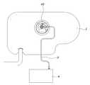
도 1은 본 발명에 따라 활성탄 필터장치가 연료펌프모듈에 구비된 연료탱크의 평면도,
도 2와 도 3은 활성탄 필터장치를 구비한 연료펌프모듈의 사시도,
도 4와 도 5는 도 2의 Ⅰ-Ⅰ선 및 Ⅱ-Ⅱ선 단면도,
도 6 내지 도 9는 퓨얼 리미트 벤트 밸브에 결합된 활성탄 필터장치를 설명하기 위한 도면이다.1 is a plan view of a fuel tank in which an activated carbon filter device according to the present invention is provided in a fuel pump module,
2 and 3 are perspective views of a fuel pump module having an activated carbon filter device,
Figs. 4 and 5 are sectional views taken along line I-I and II-II in Fig. 2,
6 to 9 are views for explaining an activated carbon filter device coupled to a fuel limit valve.
이하에서는 첨부된 도면을 참조하여 본 발명의 바람직한 일실시예에 따른 활성탄 역류방지구조를 구비한 차량의 연료 공급 장치에 대해 살펴보기로 한다.DETAILED DESCRIPTION OF THE PREFERRED EMBODIMENTS Hereinafter, a fuel supply apparatus for a vehicle having an active carbon backflow prevention structure according to a preferred embodiment of the present invention will be described with reference to the accompanying drawings.
본 발명에 따른 활성탄 역류방지구조를 구비한 차량의 연료 공급 장치는 도 1 내지 도 9에 도시된 바와 같이 연료가 보관되는 연료탱크(1), 연료탱크(1)에 설치된 연료펌프모듈(2), 연료탱크(1)에서 발생한 연료증발가스를 포집할 수 있도록 연료펌프모듈(2)과 연결관(3)을 통해서 연결된 캐니스터(4)를 포함한다.1 to 9, a fuel supply apparatus for a vehicle having an activated carbon backflow prevention structure according to the present invention includes a
상기 연료펌프모듈(2)은 연료탱크(1)에 보관된 연료를 엔진측으로 펌핑하는 연료펌프(10), 연료펌프(10)와 연결된 롤 오버 밸브(20, ROV; roll over valve), 롤 오버 밸브(20) 및 캐니스터(4)와 연결된 퓨얼 리미트 밴트 밸브(30, FLVV; fuel limit vent valve), 롤 오버 밸브(20) 및 퓨얼 리미트 벤트 밸브(30)가 장착된 상태로 연료탱크(1)에 결합되어 설치되는 밸브플레이트(40)를 포함한다.The fuel pump module 2 includes a
상기 롤 오버 밸브(20)는 차량의 전복시 연료탱크(1)에 보관된 연료의 누출을 방지하는 밸브이고, 상기 퓨얼 리미트 밴트 밸브(30)는 연료 주입시 연료탱크(1)로 주입되는 연료량을 규제함과 동시에 연료탱크(1)에서 발생한 연료증발가스를 수집해서 캐니스터(4)로 송출하는 밸브이다.The roll over
또한, 본 발명은 상기 퓨얼 리미트 벤트 밸브(30)에 구비된 것으로 연료탱크(1)에서 캐니스터(4)쪽으로의 증발가스 이동은 허용하고 캐니스터(4)로부터 역류하는 활성탄(5)은 필터링해서 롤 오버 밸브(20)쪽으로의 활성탄(5) 이동을 차단하는 활성탄 필터장치(50)를 더 포함한다.The present invention is provided in the above-mentioned Fuel
그리고, 상기 밸브플레이트(40)에는 활성탄 필터장치(50)를 커버링하는 커버부(41)가 구비되고, 또한 상기 커버부(41)와 롤 오버 밸브(20)를 연결하는 제1가스통로(42) 및 커버부(41)와 캐니스터(4)를 연결하는 제2가스통로(43)가 형성된다.The
상기 활성탄 필터장치(50)는 상단은 밀폐되고 하단은 개구되며 상하단 사이의 외곽 둘레를 따라 다수개의 윈도우(51)가 형성된 필터하우징(52); 및 상기 윈도우(51)를 커버링하도록 필터하우징(52)에 결합된 것으로 증발가스의 이동은 허용하고 활성탄(5)은 필터링하는 그물망필터(53);를 포함한다.The activated carbon filter device (50) includes a filter housing (52) having an upper end closed and a lower end opened and having a plurality of windows (51) along an outer circumference between upper and lower ends; And a mesh filter (53) coupled to the filter housing (52) to cover the window (51) and allowing movement of the evaporative gas and filtering the activated carbon (5).
상기 퓨얼 리미트 벤트 밸브(30)의 상부면에 밸브결합부(31)가 구비되고, 상기 필터하우징(52)의 개구된 하단부(52a)가 밸브결합부(31)속으로 삽입되어서 설치된다.A
상기 밸브결합부(31)에 필터하우징(52)의 하단부(52a)가 삽입된 상태일 때 필터하우징(52)은 제1가스통로(42)와 대면하는 일측의 반원통부(54) 및 제2가스통로(43)와 대면하는 타측의 반원통부(55)로 구분되고, 상기 일측의 반원통부(54)에는 배기가스의 통기저항을 줄이기 위해 통기홀(56)이 형성되면서 통기홀(56)의 주변은 강도보강을 위해 필터하우징(52)에 의해 밀폐되게 형성되며, 상기 타측의 반원통부(55)에만 윈도우(51)가 형성되고 윈도우(51)를 가리도록 그물망필터(53)가 결합된 구조가 된다.When the
상기 윈도우(51)는 필터하우징(52)의 하단부(52a) 전체에 원주방향을 따라 형성되는데, 상기 필터하우징(52)의 하단부(52a)는 밸브결합부(31)속에 삽입되도록 설치되기 때문에 외부로는 노출되지 않는 구조가 된다.The
상기 필터하우징(52)에는 밸브결합부(31)보다 직경이 큰 플랜지부(57)가 원주방향을 따라 형성되고, 상기 플랜지부(57)는 필터하우징(52)의 하단부(52a)가 밸브결합부(31)속으로 삽입될 때 밸브결합부(31)의 윗면에 안착되어서 필터하우징(52)의 삽입량을 제어하게 된다.The
상기 밸브결합부(31)에 필터하우징(52)의 하단부(52a)가 삽입될 때 일측의 반원통부(54)가 제1가스통로(42)와 대면하고 타측의 반원통부(55)가 제2가스통로(43)와 대면하게 설치될 수 있도록 필터하우징(52)에는 위치결정돌기(58)가 밸브결합부를 향해 아래로 돌출되게 형성되고, 상기 밸브결합부(31)의 상단부에는 위치결정돌기(58)가 삽입되는 위치결정홈(32)이 형성된다.When the
상기 위치결정돌기(58)가 위치결정홈(32)에 삽입된 상태일 때 하단부(52a)가 밸브결합부(31)속에 삽입된 필터하우징(52)은 위치결정돌기(58)와 위치결정홈(32)의 걸림에 의해 회전이 방지된다.The filter housing 52 in which the
상기 퓨얼 리미트 벤트 밸브(30)가 밸브플레이트(40)에 장착되면 밸브결합부(31)로부터 돌출된 필터하우징(52)의 상단부(52b)는 밸브플레이트(40)의 커버부(41)속에 삽입되게 설치되고, 상기 커버부(41)의 내경과 필터하우징(52)사이의 틈새(C1)는 증발가스의 이동은 허용하면서 활성탄(5)의 이동을 불허하는 크기로 형성된 구조를 갖는다.The
보다 상세히 설명하면, 상기 커버부(41)의 내경과 필터하우징(52)사이의 틈새(C1)가 활성탄(5)의 이동을 불허하는 크기로 형성될 수 있도록 필터하우징(52)에는 일측의 반원통부(54)와 타측의 반원통부(55)의 경계를 따라 요철형상을 갖는 격벽(59)이 일체로 형성된 구조인 것이다.The
한편, 본 발명에 따른 활성탄 필터장치(50)는 밸브결합부(31)의 윗면에 그물망필터(53)가 결합된 필터하우징(52)이 상부로 돌출되도록 밸브결합부(31)와 일체로 형성된 구조가 될 수도 있다.The activated
따라서, 후방 추돌 사고로 인해 활성탄(5)이 들어있는 캐니스터(4)가 완전히 파손된 경우, 활성탄(5)은 캐니스터(4)와 연결된 연결관(3) 및 연결관(3)이 연결된 제2가스통로(43)를 통해서 활성탄 필터장치(50)가 위치한 밸브플레이트(40)의 커버부(41)쪽으로 이동하게 된다.Therefore, when the
커버부(41)쪽으로 이동한 활성탄(5)의 일부는 제2가스통로(43)와 대면하도록 설치된 그물망필터(43)에 의해 필터링되어서 롤 오버 밸브(20)와 연결된 제1가스통로(42)쪽으로 이동하지 못하게 되고, 또한 그물망필터(43)에 의해 필터링되지 않은 나머지의 활성탄(5)들은 필터하우징(52)의 외곽 둘레를 따라 형성된 격벽(59)에 의해 모두 필터링되어서 롤 오버 밸브(20)와 연결된 제1가스통로(42)쪽으로 이동하지 못하게 된다.A portion of the activated
즉, 후방 추돌 사고로 인해 활성탄(5)이 들어있는 캐니스터(4)가 완전히 파손된 경우라 할지라도 롤 오버 밸브(20)쪽으로 활성탄(5)이 역류되는 현상을 예방할 수 있게 되고, 이 결과 후방 추돌 사고로 인해 차량이 전복된 상황일지라도 활성탄(5)에 의한 롤 오버 밸브(20)의 작동 이상 현상을 예방할 수 있게 됨으로써, 연료탱크(1)에 저장된 연료의 누출을 예방할 수 있는 장점이 있다.That is, even if the
또한, 본 발명에 따라 밸브플레이트(40)의 커버부(41)속에 활성탄 필터장치(50)가 설치된 구조로 인해, 연료 주입시 연료 주입이 조기에 종료되는 셧 오프(shut off) 현상이 발생되는 것을 방지할 수 있게 되고, 더 나아가 연료 주입시 연료탱크(1)의 과압 발생이 방지됨으로써 연료가 외부로 흘러나오는 오버 플로우(over flow) 현상의 발생을 방지할 수 있는 장점도 있다.In addition, according to the present invention, due to the structure in which the activated
즉, 퓨얼 리미트 벤트 밸브(30)의 밸브결합부(31)의 직경보다 필터하우징(52)이 설치된 밸브플레이트(40)의 커버부(41)의 내경이 더 크기 때문에 연료 주입시 상승하던 연료탱크(1)의 압력은 밸브결합부(31)를 통과하면서 해소되고, 이로 인해 연료 주입이 조기에 종료되는 셧 오프(shut off) 현상의 발생이 방지됨에 따라 연료의 충분한 주입이 가능해지며, 더 나아가 연료 주입시 연료탱크(1)의 과압 발생이 방지됨으로써 연료가 외부로 흘러나오는 오버 플로우(over flow) 현상의 발생을 방지할 수 있게 되는 것이다.That is, since the inner diameter of the
본 발명은 특정한 실시예에 관련하여 도시하고 설명하였지만, 이하의 특허청구범위에 의해 제공되는 본 발명의 기술적 사상을 벗어나지 않는 한도 내에서, 본 발명이 다양하게 개량 및 변화될 수 있다는 것은 당업계에서 통상의 지식을 가진 자에게 있어서 자명할 것이다.While the present invention has been particularly shown and described with reference to specific embodiments thereof, it will be understood by those skilled in the art that various changes in form and details may be made therein without departing from the spirit and scope of the invention as defined by the following claims It will be apparent to those of ordinary skill in the art.
1 - 연료탱크 2 - 연료펌프모듈
3 - 연결관 4 - 캐니스터
5 - 활성탄 10 - 연료펌프
20 - 롤 오버 밸브 30 - 퓨얼 리미트 벤트 밸브
40 - 밸브플레이트 50 - 활성탄 필터장치1 - Fuel tank 2 - Fuel pump module
3 - Connector 4 - Canister
5 - Activated carbon 10 - Fuel pump
20 - Roll over valve 30 - Fuel limit vent valve
40 - Valve plate 50 - Activated carbon filter device
Claims (9)
Translated fromKorean밸브플레이트의 커버부 내측에 설치되어 커버링되며 퓨얼 리미트 벤트 밸브의 상부에 구비되고, 연료탱크에서 캐니스터쪽으로의 제2가스통로를 통한 증발가스의 이동은 허용하고, 캐니스터로부터 제2가스통로를 통해 역류하는 활성탄은 필터링해서 제1가스통로를 통한 롤 오버 밸브쪽으로의 활성탄 이동을 차단하는 활성탄 필터장치;를 포함하고,
커버부의 내경과 활성탄 필터장치의 외경 사이 틈새는 증발가스의 이동은 허용하면서 활성탄의 이동을 불허하는 크기로 형성된 것을 특징으로 하는 활성탄 역류방지구조를 구비한 차량의 연료 공급 장치.A first gas passage connected to the fuel tank in a state where the fuel limit valve and the roll-over valve are mounted and having a cover portion and connecting the cover portion and the rollover valve, and a second gas passage connecting the cover portion and the canister A formed valve plate; And
Limit valve disposed on the inside of the cover portion of the valve plate and provided on the upper portion of the fuel limit valve to permit movement of the evaporative gas through the second gas passage from the fuel tank to the canister, And an activated carbon filter device for filtering the activated carbon to block the movement of activated carbon toward the roll-over valve through the first gas passage,
Wherein the clearance between the inner diameter of the cover and the outer diameter of the activated carbon filter device is such that the movement of the activated carbon is prohibited while permitting the movement of the evaporation gas.
상기 활성탄 필터장치는 상단은 밀폐되고 하단은 개구되며 상하단 사이의 외곽 둘레를 따라 다수개의 윈도우가 형성된 필터하우징; 및
상기 윈도우를 커버링하도록 필터하우징에 결합된 것으로 증발가스의 이동은 허용하고 활성탄은 필터링하는 그물망필터;를 포함하는 것을 특징으로 하는 활성탄 역류방지구조를 구비한 차량의 연료 공급 장치.The method according to claim 1,
The activated carbon filter device includes a filter housing having an upper end closed and a lower end opened and having a plurality of windows along an outer circumference between upper and lower ends; And
And a mesh filter coupled to the filter housing to cover the window, the mesh filter allowing movement of the evaporation gas and filtering the activated carbon.
상기 퓨얼 리미트 벤트 밸브의 상부면에 밸브결합부가 구비되고;
상기 필터하우징의 개구된 하단부가 밸브결합부속으로 삽입되어서 설치된 것을 특징으로 하는 활성탄 역류방지구조를 구비한 차량의 연료 공급 장치.The method of claim 2,
A valve engagement portion is provided on an upper surface of the fuel limit vent valve;
And an open lower end of the filter housing is inserted into the valve engagement member.
상기 밸브결합부에 필터하우징의 하단부가 삽입된 상태일 때 필터하우징은 제1가스통로와 대면하는 일측의 반원통부 및 제2가스통로와 대면하는 타측의 반원통부로 구분되고;
상기 일측의 반원통부에는 배기가스의 통기저항을 줄이기 위해 통기홀이 형성되면서 통기홀의 주변은 강도보강을 위해 필터하우징에 의해 밀폐되게 형성되며;
상기 타측의 반원통부에만 윈도우가 형성되고 윈도우를 가리도록 그물망필터가 결합된 것을 특징으로 하는 활성탄 역류방지구조를 구비한 차량의 연료 공급 장치.The method of claim 3,
Wherein the filter housing is divided into one semicircular tube portion facing the first gas passage and the other semicircular tube portion facing the second gas passage when the lower end portion of the filter housing is inserted into the valve engagement portion;
A vent hole is formed in the semicircular tube at one side to reduce the ventilation resistance of the exhaust gas, and the periphery of the vent hole is formed to be sealed by the filter housing for strength reinforcement;
And a mesh filter is coupled to form a window only on the other half-cylindrical portion and to cover the window.
상기 필터하우징에는 밸브결합부보다 직경이 큰 플랜지부가 원주방향을 따라 형성되고;
상기 플랜지부는 필터하우징의 하단부가 밸브결합부속으로 삽입될 때 밸브결합부의 윗면에 안착되어서 필터하우징의 삽입량을 제어하는 것을 특징으로 하는 활성탄 역류방지구조를 구비한 차량의 연료 공급 장치.The method of claim 3,
Wherein the filter housing is formed with a flange portion having a larger diameter than the valve engagement portion along the circumferential direction;
Wherein the flange portion is seated on the upper surface of the valve engagement portion when the lower end portion of the filter housing is inserted into the valve engagement portion to control the insertion amount of the filter housing.
상기 밸브결합부에 필터하우징의 하단부가 삽입될 때 일측의 반원통부가 제1가스통로와 대면하고 타측의 반원통부가 제2가스통로와 대면하게 설치될 수 있도록 필터하우징에는 위치결정돌기가 밸브결합부를 향해 아래로 돌출되게 형성되고;
상기 밸브결합부의 상단부에는 위치결정돌기가 삽입되는 위치결정홈이 형성된 것을 특징으로 하는 활성탄 역류방지구조를 구비한 차량의 연료 공급 장치.The method of claim 4,
Wherein when the lower end portion of the filter housing is inserted into the valve coupling portion, the semi-cylindrical portion on one side faces the first gas passage and the semi-cylindrical portion on the other side faces the second gas passage, And protruding downward toward the part;
Wherein the valve coupling portion is formed with a positioning groove into which a positioning protrusion is inserted, at an upper end of the valve coupling portion.
상기 퓨얼 리미트 벤트 밸브가 밸브플레이트에 장착되면 밸브결합부로부터 돌출된 필터하우징의 상단부는 밸브플레이트의 커버부속에 삽입되게 설치되고;
상기 커버부의 내경과 필터하우징사이의 틈새는 증발가스의 이동은 허용하면서 활성탄의 이동을 불허하는 크기로 형성된 것을 특징으로 하는 활성탄 역류방지구조를 구비한 차량의 연료 공급 장치.The method of claim 4,
When the fuel limit valve is mounted on the valve plate, the upper end of the filter housing protruding from the valve fitting portion is installed to be inserted into the cover of the valve plate;
Wherein a gap between the inner diameter of the cover portion and the filter housing is formed to a size that allows movement of the activated carbon while allowing movement of the evaporated gas.
상기 커버부의 내경과 필터하우징사이의 틈새가 활성탄의 이동을 불허하는 크기로 형성될 수 있도록 필터하우징에는 일측의 반원통부와 타측의 반원통부의 경계를 따라 요철형상을 갖는 격벽이 일체로 형성된 것을 특징으로 하는 활성탄 역류방지구조를 구비한 차량의 연료 공급 장치.The method of claim 4,
The filter housing is integrally formed with a partition wall having a concavo-convex shape along the boundary between the semicircular tubular portion and the other semicircular tubular portion so that the gap between the inner diameter of the cover portion and the filter housing can be formed to a size that does not allow the activated carbon to move. Wherein the activated carbon backflow preventive structure is provided in the fuel tank.
상기 퓨얼 리미트 벤트 밸브의 상부면에 밸브결합부가 구비되고;
상기 밸브결합부의 윗면에 그물망필터가 결합된 필터하우징이 상부로 돌출되게 일체로 형성된 것을 특징으로 하는 활성탄 역류방지구조를 구비한 차량의 연료 공급 장치.The method of claim 2,
A valve engagement portion is provided on an upper surface of the fuel limit vent valve;
And a filter housing having a mesh filter coupled to an upper surface of the valve coupling portion is integrally formed to protrude upward.
Priority Applications (1)
| Application Number | Priority Date | Filing Date | Title |
|---|---|---|---|
| KR1020160022446AKR101834215B1 (en) | 2016-02-25 | 2016-02-25 | Fuel supply apparatus for flowing backward prevention of charcoal |
Applications Claiming Priority (1)
| Application Number | Priority Date | Filing Date | Title |
|---|---|---|---|
| KR1020160022446AKR101834215B1 (en) | 2016-02-25 | 2016-02-25 | Fuel supply apparatus for flowing backward prevention of charcoal |
Publications (2)
| Publication Number | Publication Date |
|---|---|
| KR20170100702A KR20170100702A (en) | 2017-09-05 |
| KR101834215B1true KR101834215B1 (en) | 2018-03-07 |
Family
ID=59924981
Family Applications (1)
| Application Number | Title | Priority Date | Filing Date |
|---|---|---|---|
| KR1020160022446AActiveKR101834215B1 (en) | 2016-02-25 | 2016-02-25 | Fuel supply apparatus for flowing backward prevention of charcoal |
Country Status (1)
| Country | Link |
|---|---|
| KR (1) | KR101834215B1 (en) |
Families Citing this family (1)
| Publication number | Priority date | Publication date | Assignee | Title |
|---|---|---|---|---|
| JP6886434B2 (en) | 2018-07-27 | 2021-06-16 | 株式会社ニフコ | Fuel tank valve gear |
Citations (2)
| Publication number | Priority date | Publication date | Assignee | Title |
|---|---|---|---|---|
| US20050098160A1 (en)* | 2003-11-12 | 2005-05-12 | Taxon Morse N. | Fuel vent assembly with floatless rollover protection |
| US20150369182A1 (en)* | 2014-06-18 | 2015-12-24 | Stoneridge, Inc. | Inline dump-able fuel system dust filter with pressure relief valve |
- 2016
- 2016-02-25KRKR1020160022446Apatent/KR101834215B1/enactiveActive
Patent Citations (2)
| Publication number | Priority date | Publication date | Assignee | Title |
|---|---|---|---|---|
| US20050098160A1 (en)* | 2003-11-12 | 2005-05-12 | Taxon Morse N. | Fuel vent assembly with floatless rollover protection |
| US20150369182A1 (en)* | 2014-06-18 | 2015-12-24 | Stoneridge, Inc. | Inline dump-able fuel system dust filter with pressure relief valve |
Also Published As
| Publication number | Publication date |
|---|---|
| KR20170100702A (en) | 2017-09-05 |
Similar Documents
| Publication | Publication Date | Title |
|---|---|---|
| JP5961026B2 (en) | Evaporative fuel processing equipment | |
| US6675779B2 (en) | Dual float valve for fuel tank vent with liquid carryover filter | |
| CN103174568B (en) | Fuel ventilation system valve | |
| JP6275634B2 (en) | Flow control valve and evaporated fuel processing device | |
| US9371803B2 (en) | Valve assembly | |
| JP6287581B2 (en) | Evaporative fuel processing equipment | |
| US9340105B2 (en) | Fuel tank opening-closing device | |
| EP3575587B1 (en) | Evaporative emissions control system leak check module including first and second solenoid valves | |
| JP2006258101A (en) | Vapor vent valve integrally equipped with pressure relief function for canister | |
| KR20080098623A (en) | Leak Detection Methods and Associated Valves and Fuel Systems | |
| MX2012006013A (en) | Valve assembly for a fuel recirculation line. | |
| EP1300579A2 (en) | Fuel tank ventilation valve for internal combustion engines | |
| KR101040965B1 (en) | Canister with differential outflow prevention structure | |
| EP2051873B1 (en) | Improved fuel vapour adsorbing device | |
| KR101834215B1 (en) | Fuel supply apparatus for flowing backward prevention of charcoal | |
| KR101734680B1 (en) | Canister apparatus of vehicle | |
| US10857876B2 (en) | Filler inlet with fluid separation | |
| JP6551213B2 (en) | Fuel return device | |
| JP2018193921A (en) | Sealed tank system | |
| JP6399278B2 (en) | Vehicle fuel tank system | |
| EP2071172A1 (en) | Canister with overmolded filter | |
| US20150068617A1 (en) | Valve and fuel tank structure | |
| JP2019044604A (en) | Drain device | |
| KR200316648Y1 (en) | The efflux preventing structure of active carbon for canister | |
| US9347403B2 (en) | Fuel tank |
Legal Events
| Date | Code | Title | Description |
|---|---|---|---|
| A201 | Request for examination | ||
| PA0109 | Patent application | Patent event code:PA01091R01D Comment text:Patent Application Patent event date:20160225 | |
| PA0201 | Request for examination | ||
| E902 | Notification of reason for refusal | ||
| PE0902 | Notice of grounds for rejection | Comment text:Notification of reason for refusal Patent event date:20170618 Patent event code:PE09021S01D | |
| PG1501 | Laying open of application | ||
| E701 | Decision to grant or registration of patent right | ||
| PE0701 | Decision of registration | Patent event code:PE07011S01D Comment text:Decision to Grant Registration Patent event date:20171201 | |
| PR0701 | Registration of establishment | Comment text:Registration of Establishment Patent event date:20180226 Patent event code:PR07011E01D | |
| PR1002 | Payment of registration fee | Payment date:20180227 End annual number:3 Start annual number:1 | |
| PG1601 | Publication of registration | ||
| PR1001 | Payment of annual fee | Payment date:20210224 Start annual number:4 End annual number:4 | |
| PR1001 | Payment of annual fee | Payment date:20211230 Start annual number:5 End annual number:5 | |
| PR1001 | Payment of annual fee | Payment date:20230207 Start annual number:6 End annual number:6 | |
| PR1001 | Payment of annual fee | Payment date:20240221 Start annual number:7 End annual number:7 |