KR101831660B1 - Active catheter apparatus and control system thereof - Google Patents
Active catheter apparatus and control system thereofDownload PDFInfo
- Publication number
- KR101831660B1 KR101831660B1KR1020160132399AKR20160132399AKR101831660B1KR 101831660 B1KR101831660 B1KR 101831660B1KR 1020160132399 AKR1020160132399 AKR 1020160132399AKR 20160132399 AKR20160132399 AKR 20160132399AKR 101831660 B1KR101831660 B1KR 101831660B1
- Authority
- KR
- South Korea
- Prior art keywords
- catheter
- guide wire
- magnet
- active
- magnetic field
- Prior art date
- Legal status (The legal status is an assumption and is not a legal conclusion. Google has not performed a legal analysis and makes no representation as to the accuracy of the status listed.)
- Active
Links
- 238000010586diagramMethods0.000description13
- 210000004204blood vesselAnatomy0.000description11
- 208000007536ThrombosisDiseases0.000description3
- 238000005452bendingMethods0.000description3
- 208000036829Device dislocationDiseases0.000description2
- 230000001141propulsive effectEffects0.000description2
- 230000001419dependent effectEffects0.000description1
- 239000000284extractSubstances0.000description1
- RFHAOTPXVQNOHP-UHFFFAOYSA-NfluconazoleChemical compoundC1=NC=NN1CC(C=1C(=CC(F)=CC=1)F)(O)CN1C=NC=N1RFHAOTPXVQNOHP-UHFFFAOYSA-N0.000description1
- 239000012530fluidSubstances0.000description1
- 230000003902lesionEffects0.000description1
- 238000013507mappingMethods0.000description1
- 238000002324minimally invasive surgeryMethods0.000description1
- 210000000056organAnatomy0.000description1
- 230000037361pathwayEffects0.000description1
- 230000002093peripheral effectEffects0.000description1
- 230000001360synchronised effectEffects0.000description1
Images


Classifications
- A—HUMAN NECESSITIES
- A61—MEDICAL OR VETERINARY SCIENCE; HYGIENE
- A61M—DEVICES FOR INTRODUCING MEDIA INTO, OR ONTO, THE BODY; DEVICES FOR TRANSDUCING BODY MEDIA OR FOR TAKING MEDIA FROM THE BODY; DEVICES FOR PRODUCING OR ENDING SLEEP OR STUPOR
- A61M25/00—Catheters; Hollow probes
- A61M25/01—Introducing, guiding, advancing, emplacing or holding catheters
- A61M25/0105—Steering means as part of the catheter or advancing means; Markers for positioning
- A61M25/0133—Tip steering devices
- A61M25/0158—Tip steering devices with magnetic or electrical means, e.g. by using piezo materials, electroactive polymers, magnetic materials or by heating of shape memory materials
- A—HUMAN NECESSITIES
- A61—MEDICAL OR VETERINARY SCIENCE; HYGIENE
- A61M—DEVICES FOR INTRODUCING MEDIA INTO, OR ONTO, THE BODY; DEVICES FOR TRANSDUCING BODY MEDIA OR FOR TAKING MEDIA FROM THE BODY; DEVICES FOR PRODUCING OR ENDING SLEEP OR STUPOR
- A61M25/00—Catheters; Hollow probes
- A61M25/01—Introducing, guiding, advancing, emplacing or holding catheters
- A61M25/09—Guide wires
- A61M25/09041—Mechanisms for insertion of guide wires
- A—HUMAN NECESSITIES
- A61—MEDICAL OR VETERINARY SCIENCE; HYGIENE
- A61M—DEVICES FOR INTRODUCING MEDIA INTO, OR ONTO, THE BODY; DEVICES FOR TRANSDUCING BODY MEDIA OR FOR TAKING MEDIA FROM THE BODY; DEVICES FOR PRODUCING OR ENDING SLEEP OR STUPOR
- A61M2205/00—General characteristics of the apparatus
- A61M2205/33—Controlling, regulating or measuring
Landscapes
- Health & Medical Sciences (AREA)
- Life Sciences & Earth Sciences (AREA)
- Biophysics (AREA)
- Pulmonology (AREA)
- Engineering & Computer Science (AREA)
- Anesthesiology (AREA)
- Biomedical Technology (AREA)
- Heart & Thoracic Surgery (AREA)
- Hematology (AREA)
- Animal Behavior & Ethology (AREA)
- General Health & Medical Sciences (AREA)
- Public Health (AREA)
- Veterinary Medicine (AREA)
- Media Introduction/Drainage Providing Device (AREA)
Abstract
Translated fromKoreanDescription
Translated fromKorean본 발명은 능동형 카테터 장치 및 이의 제어 시스템에 관한 것으로, 보다 상세하게는 외부 자기장에 의해 이동 및 조향이 가능하고, 자동으로 환부 위치까지 이동할 수 있는 능동형 카테터 장치 및 이의 제어 시스템에 관한 것이다.BACKGROUND OF THE INVENTION 1. Field of the Invention The present invention relates to an active catheter apparatus and a control system thereof, and more particularly, to an active catheter apparatus and its control system capable of being moved and steered by an external magnetic field and automatically moving to a lesion site.
기관, 체강, 통로, 조직 등의 관찰 또는 치료를 위하여 최소로 절개하는 시술을 함에 있어 카테터(catheter) 등과 같은 의료 기기들이 사용된다. 그리고, 이러한 카테터 등의 의료 기기를 혈관 내 소정 위치로 안내하기 위해 가이드 와이어가 널리 사용되고 있다.Medical devices such as catheters are used in minimally invasive procedures for observation or treatment of organs, body cavities, pathways, tissues, and the like. A guide wire is widely used to guide a medical device such as a catheter to a predetermined position in a blood vessel.
카테터는 가이드 와이어를 따라 삽입되며, 가이드 와이어는 해부학적으로 제한된 공간 내에서 사용되기 때문에 신체 내부에서 조향 가능하거나, 운용 가능한 것이 바람직하다. 이러한 가이드 와이어의 조향은 운용자가 신체 내의 가이드 와이어를 안내하고 가이드 와이어에 장착된 기구를 해부학적 지표(anatomical landmark)에 정확하게 위치시키는 것을 가능하게 한다.The catheter is inserted along the guide wire, and since the guide wire is used within anatomically limited space, it is preferable that the catheter is steerable or operable inside the body. This steering of the guide wire allows the operator to guide the guide wire in the body and accurately position the mechanism mounted on the guide wire to the anatomical landmark.
이러한 가이드 와이어 및 카테터 등을 이용하여 혈관 내의 혈전 등을 드릴링할 수 있으며, 체내에서 이동시키기 위해 외부 자기장을 이용하는 연구가 많이 진행되고 있다.Thrombosis and the like in blood vessels can be drilled by using such a guide wire and a catheter, and studies using an external magnetic field for moving in the body have been conducted.
본 발명은 상기 문제점을 해결하기 위한 것으로, 외부 자기장에 의해 이동 및 조향이 가능하고, 자동으로 환부 위치까지 이동할 수 있는 능동형 카테터 장치 및 이의 제어 시스템을 제공한다.SUMMARY OF THE INVENTION The present invention provides an active catheter apparatus and its control system capable of being moved and steered by an external magnetic field and automatically moving to an affected site.
본 발명이 해결하고자 하는 과제들은 이상에서 언급한 과제들로 제한되지 않으며, 언급되지 않은 또 다른 과제들은 아래의 기재로부터 당업자에게 명확하게 이해될 수 있을 것이다.The problems to be solved by the present invention are not limited to the above-mentioned problems, and other matters not mentioned can be clearly understood by those skilled in the art from the following description.
상기 과제를 달성하기 위한 본 발명의 일 실시예에 따른 능동형 카테터 장치는, 가이드 와이어와, 경방향으로 자기 배향되는 제1 자석과, 상기 가이드 와이어와 상기 제1 자석을 연결하는 조인트와, 상기 제1 자석의 전단에 형성되는 전단 팁을 포함하는 가이드 와이어 모듈; 및 상기 가이드 와이어가 내부에 삽입되는 카테터 도관과, 상기 카테터 도관의 외면에 배치되는 경방향으로 자기 배향되는 제2 자석을 포함하는 카테터 모듈을 포함하고, 상기 가이드 와이어 모듈은, 상기 제1 자석의 외주면에 나사선이 형성된다.According to an aspect of the present invention, there is provided an active catheter apparatus including a guide wire, a first magnet that is self-aligned in a radial direction, a joint that connects the guide wire and the first magnet, A guide wire module including a front end tip formed at a front end of the one magnet; And a catheter module including a catheter conduit into which the guide wire is inserted and a second magnet that is radially self-orientated disposed on an outer surface of the catheter conduit, wherein the guide wire module comprises: A thread is formed on the outer circumferential surface.
삭제delete
또한, 상기 가이드 와이어 모듈은, 일단에 상기 조인트가 연결되고, 타단에 상기 제1 자석이 연결되며, 상기 조인트 및 상기 제1 자석을 수용하는 나사선 블레이드를 더 포함할 수 있다.The guide wire module may further include a threaded blade, the joint being connected to one end of the guide wire module, the first magnet connected to the other end, and the joint and the first magnet.
또한, 상기 카테터 모듈은, 상기 카테터 도관의 외면에 상기 제2 자석이 배치되는 배치홈을 구비할 수 있다.In addition, the catheter module may include an arrangement groove on the outer surface of the catheter catheter in which the second magnet is disposed.
그리고, 상기 카테터 모듈은, 상기 제2 자석의 내경이 상기 카테터 도관의 배치홈의 외경보다 크게 형성될 수 있다.In the catheter module, an inner diameter of the second magnet may be formed to be larger than an outer diameter of an arrangement groove of the catheter conduit.
상기 과제를 달성하기 위한 본 발명의 일 실시예에 따른 능동형 카테터 장치의 제어 시스템은, 상술한 능동형 카테터 장치; 상기 능동형 카테터 장치를 밀어 주는 푸시 장치; 상기 능동형 카테터 장치에 회전 자기장을 인가하는 자기장 인가 장치; 및 상기 푸시 장치 및 상기 자기장 인가 장치를 제어하여 상기 능동형 카테터 장치의 이동을 제어하는 제어 장치를 포함한다.According to an aspect of the present invention, there is provided a control system for an active catheter apparatus, comprising: the active catheter apparatus described above; A pushing device for pushing the active catheter device; A magnetic field application device for applying a rotating magnetic field to the active catheter device; And a control device for controlling the movement of the active catheter device by controlling the push device and the magnetic field applying device.
또한, 상기 푸시 장치는, 상기 능동형 카테터 장치의 이동을 가이드하는 복수의 롤러와, 상기 복수의 롤러에 각각 구동력을 제공하는 복수의 모터를 포함할 수 있다.The pushing device may include a plurality of rollers for guiding movement of the active catheter device, and a plurality of motors for respectively providing driving force to the plurality of rollers.
또한, 상기 제어 장치는, 상기 능동형 카테터 장치의 상기 가이드 와이어 모듈의 이동 속도와 상기 푸시 장치의 푸시 속도를 동기화할 수 있다.In addition, the control device can synchronize the moving speed of the guide wire module of the active catheter device with the pushing speed of the pushing device.
또한, 상기 능동형 카테터 장치의 가이드 와이어 모듈의 위치 및 이동 속도를 검출하는 센싱 장치를 더 포함할 수 있다.The apparatus may further include a sensing device for sensing a position and a moving speed of the guide wire module of the active catheter device.
그리고, 상기 제어 장치는, 상기 가이드 와이어 모듈의 위치 및 이동 속도에 기초하여 상기 푸시 장치 및 상기 자기장 인가 장치를 제어하고, 상기 능동형 카테터 장치를 타겟 위치까지 이동시킬 수 있다.Then, the control device controls the push device and the magnetic field applying device based on the position and the moving speed of the guide wire module, and can move the active catheter device to the target position.
본 발명의 기타 구체적인 사항들은 상세한 설명 및 도면들에 포함되어 있다.Other specific details of the invention are included in the detailed description and drawings.
본 발명에 따르면, 외부 자기장에 의해 가이드 와이어 및 카테터의 이동 및 조향이 가능하고, 자동으로 환부 위치까지 이동시킬 수 있다.According to the present invention, the guide wire and the catheter can be moved and steered by an external magnetic field, and can be automatically moved to the affected part position.
도 1은 본 발명의 일 실시예에 따른 능동형 카테터 장치의 구성도이다.
도 2는 능동형 카테터 장치의 가이드 와이어 모듈의 일 실시예를 도시한 구성도이다.
도 3은 능동형 카테터 장치의 카테터 모듈에 사용되는 자석의 일 실시예를 도시한 도면이다.
도 4는 능동형 카테터 장치의 카테터 모듈의 일 실시예를 도시한 구성도이다.
도 5는 본 발명의 일 실시예에 따른 능동형 카테터 장치의 제어 시스템의 구성도이다.
도 6은 능동형 카테터 장치의 제어 시스템의 푸시 장치의 일 실시예를 도시한 구성도이다.
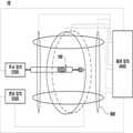
도 7은 회전 자기장의 개념을 도시한 도면이다.
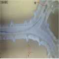
도 8a 및 도 8b는 각각 능동형 카테터 장치의 제어 시스템에 의해 이동하는 능동형 카테터 장치를 촬영한 사진을 도시한 도면이다.1 is a configuration diagram of an active catheter apparatus according to an embodiment of the present invention.
2 is a block diagram illustrating an embodiment of a guide wire module of an active catheter device.
3 is a view showing one embodiment of a magnet used in a catheter module of an active catheter device.
4 is a block diagram illustrating an embodiment of a catheter module of an active catheter device.
5 is a block diagram of a control system of an active catheter apparatus according to an embodiment of the present invention.
6 is a configuration diagram showing an embodiment of a push device of a control system of an active catheter apparatus.
7 is a diagram showing the concept of a rotating magnetic field.
FIGS. 8A and 8B are photographs showing an active catheter device moved by a control system of an active catheter device, respectively. FIG.
이하, 첨부된 도면을 참조하여 본 발명의 바람직한 실시예를 상세히 설명한다. 본 발명의 이점 및 특징, 그리고 그것들을 달성하는 방법은 첨부되는 도면과 함께 상세하게 후술되어 있는 실시예들을 참조하면 명확해질 것이다. 그러나 본 발명은 이하에서 개시되는 실시예들에 한정되는 것이 아니라 서로 다른 다양한 형태로 구현될 것이며, 단지 본 실시예들은 본 발명의 개시가 완전하도록 하며, 본 발명이 속하는 기술분야에서 통상의 지식을 가진 자에게 발명의 범주를 완전하게 알려주기 위해 제공되는 것이며, 본 발명은 청구항의 범주에 의해 정의될 뿐이다. 명세서 전체에 걸쳐 동일 참조 부호는 동일 구성 요소를 지칭한다.Hereinafter, preferred embodiments of the present invention will be described in detail with reference to the accompanying drawings. BRIEF DESCRIPTION OF THE DRAWINGS The advantages and features of the present invention and the manner of achieving them will become apparent with reference to the embodiments described in detail below with reference to the accompanying drawings. The present invention may, however, be embodied in many different forms and should not be construed as being limited to the embodiments set forth herein. Rather, these embodiments are provided so that this disclosure will be thorough and complete, and will fully convey the scope of the invention to those skilled in the art. Is provided to fully convey the scope of the invention to those skilled in the art, and the invention is only defined by the scope of the claims. Like reference numerals refer to like elements throughout the specification.
비록 제1, 제2 등이 다양한 소자, 구성요소 및/또는 섹션들을 서술하기 위해서 사용되나, 이들 소자, 구성요소 및/또는 섹션들은 이들 용어에 의해 제한되지 않음은 물론이다. 이들 용어들은 단지 하나의 소자, 구성요소 또는 섹션들을 다른 소자, 구성요소 또는 섹션들과 구별하기 위하여 사용하는 것이다. 따라서, 이하에서 언급되는 제1 소자, 제1 구성요소 또는 제1 섹션은 본 발명의 기술적 사상 내에서 제2 소자, 제2 구성요소 또는 제2 섹션일 수도 있음은 물론이다.Although the first, second, etc. are used to describe various elements, components and / or sections, it is needless to say that these elements, components and / or sections are not limited by these terms. These terms are only used to distinguish one element, element or section from another element, element or section. Therefore, it goes without saying that the first element, the first element or the first section mentioned below may be the second element, the second element or the second section within the technical spirit of the present invention.
본 명세서에서 사용된 용어는 실시예들을 설명하기 위한 것이며 본 발명을 제한하고자 하는 것은 아니다. 본 명세서에서, 단수형은 문구에서 특별히 언급하지 않는 한 복수형도 포함한다. 명세서에서 사용되는 "포함한다(comprises)" 및/또는 "이루어지다(made of)"는 언급된 구성요소, 단계, 동작 및/또는 소자는 하나 이상의 다른 구성요소, 단계, 동작 및/또는 소자의 존재 또는 추가를 배제하지 않는다.The terminology used herein is for the purpose of illustrating embodiments and is not intended to be limiting of the present invention. In the present specification, the singular form includes plural forms unless otherwise specified in the specification. As used herein, the terms "comprises" and / or "made of" means that a component, step, operation, and / or element may be embodied in one or more other components, steps, operations, and / And does not exclude the presence or addition thereof.
다른 정의가 없다면, 본 명세서에서 사용되는 모든 용어(기술 및 과학적 용어를 포함)는 본 발명이 속하는 기술분야에서 통상의 지식을 가진 자에게 공통적으로 이해될 수 있는 의미로 사용될 수 있을 것이다. 또 일반적으로 사용되는 사전에 정의되어 있는 용어들은 명백하게 특별히 정의되어 있지 않는 한 이상적으로 또는 과도하게 해석되지 않는다.Unless defined otherwise, all terms (including technical and scientific terms) used herein may be used in a sense commonly understood by one of ordinary skill in the art to which this invention belongs. Also, commonly used predefined terms are not ideally or excessively interpreted unless explicitly defined otherwise.
이하, 본 발명에 대하여 첨부된 도면에 따라 보다 상세히 설명한다.Hereinafter, the present invention will be described in more detail with reference to the accompanying drawings.
도 1은 본 발명의 일 실시예에 따른 능동형 카테터 장치의 구성도이다. 또한, 도 2는 능동형 카테터 장치의 가이드 와이어 모듈의 일 실시예를 도시한 구성도이다. 또한, 도 3은 능동형 카테터 장치의 카테터 모듈에 사용되는 자석의 일 실시예를 도시한 도면이다. 그리고, 도 4는 능동형 카테터 장치의 카테터 모듈의 일 실시예를 도시한 구성도이다.1 is a configuration diagram of an active catheter apparatus according to an embodiment of the present invention. 2 is a configuration diagram showing an embodiment of a guide wire module of an active catheter apparatus. 3 is a diagram illustrating an embodiment of a magnet used in a catheter module of an active catheter device. 4 is a configuration diagram showing an embodiment of a catheter module of an active catheter apparatus.
도 1을 참조하면, 본 발명의 일 실시예에 따른 능동형 카테터 장치(100)는 가이드 와이어 모듈(110) 및 카테터 모듈(120)을 포함한다. 여기에서, 가이드 와이어 모듈(110)은 가이드 와이어(112)와, 경방향으로 자기 배향되는 제1 자석(114)과, 상기 가이드 와이어(112)와 상기 제1 자석(114)을 연결하는 조인트(116)와, 상기 제1 자석(114)의 전단에 형성되는 전단 팁(118)을 포함한다. 또한 카테터 모듈(120)은 가이드 와이어(112)가 내부에 삽입되는 카테터 도관(122)과, 상기 카테터 도관(122)의 외면에 배치되는 경방향으로 자기 배향되는 제2 자석(124)을 포함한다. 가이드 와이어 모듈(110) 및 카테터 모듈(120)이 각각 자석을 구비하며, 외부에서 가해지는 자기장에 의해 가이드 와이어 모듈(110) 및 카테터 모듈(120)의 이동 및 조향이 가능하다.Referring to FIG. 1, an
가이드 와이어 모듈(110)은 카테터 모듈(120)을 신체 내부의 소정 위치로 안내한다. 가이드 와이어 모듈(110)의 가이드 와이어(112)를 따라 카테터 모듈(120)이 혈관 등의 내부로 삽입된다.The
가이드 와이어(112)는 조인트(116)에 의해 가이드 와이어(112)와 제1 자석(114)이 연결되며, 가이드 와이어(112)는 카테터 도관(122)의 도관에 삽입된다.The
제1 자석(114)은 외부에서 가해지는 자기장에 의해 가이드 와이어(112)의 이동 및 조향이 가능하다. 특히, 외부에서 가해지는 자기장을 조절하여 가이드 와이어(112)의 각도 회전을 할때 요구되는 각도 값에 정확히 도달할 수 있고, 가이드 와이어(112)를 이동하지 않고도 제자리에서 가이드 와이어(112)의 방향을 전환할 수 있다. 제1 자석(114)은 경방향으로 자기 배향되어 있으므로, 외부 자기장으로 회전 자기장이 인가되어 이동 및 조향될 수 있다. 회전 자기장에 동기화되어 제1 자석(114)이 이동한다. 또한, 회전 자기장의 평면이 회전할 때, 그 회전 방향으로 자기 토크에 의하여 경방향으로 배향된 제1 자석(114)이 회전하게 된다. 즉, 회전 자기장의 평면이 변화할 때 자기 토크에 의하여 제1 자석(114)이 조향되며, 가이드 와이어(112)가 굽어짐 없이 조인트(116)에 의하여 조향 각도를 만들어 낸다. 조인트(116)의 회전각도 이상으로 제1 자석(114)이 조향될 때, 가이드 와이어(112)의 벤딩이 발생하여 더 큰 조향 각도를 만들어 낼 수 있다. 또한, 회전 자기장의 평면을 회전시켜 제1 자석(114)을 제자리에서 조향 각도를 조절할 수 있다. 만일, 조인트(116)로 연결되지 않는 경우, 제1 자석(114)의 조향 각도는 가이드 와이어(110)의 유연성에 의해 결정될 수 밖에 없다.The
또한, 제1 자석(114)은 외주면에 나사선(114A)이 형성될 수 있다. 회전 자기장이 인가될 경우에는 제1 자석(114)의 나사선(114A)에 의해 제1 자석(114) 자체가 회전하면서 전진한다. 나사선(114A)에 의해 제1 자석(114)이 회전하여 추진력을 얻을 수 있다. 또한, 회전 자기장이 가해지는 방향을 180도 반전시키면 제1 자석(114)에 의한 추진력의 방향을 180도 바꿀 수 있다. 그리고, 도면에는 도시하지 않았으나, 제1 자석(114)의 외주면뿐만 아니라, 제1 자석(114)의 내주면에 나사선이 형성될 수 있다. 내주면에 나사선이 없는 경우, 외부의 나사선(114A)에 의한 마찰이 낮으면 추진력이 낮게 발생할 수 있고, 특히 유체 내에서 능동형 카테터 장치(100) 내부에 위치한 스텐트 등 다른 구조물과 분리하기 어려울 수 있다. 그러나, 내부에 나사선이 있는 경우, 외부의 마찰력이 낮아도 내부의 나사선과 이에 맞닿은 내부에 있는 스텐트 등의 구조물과의 마찰에 의해 원활하게 가이드 와이어 모듈(110)을 이동시키고, 스텐트 등 다른 구조물과 쉽게 분리할 수 있다. 즉, 내외부에 나사선이 있을 경우에는 내부의 마찰력과 외부의 마찰력 중 하나만 있더라도 제1 자석(114)의 이동에 필요한 추진력을 얻을 수 있다.Also, the
조인트(116)는 가이드 와이어(112)와 제1 자석(114)을 연결하며, 제1 자석(114)의 회전 시 가이드 와이어(112)가 회전하기 않도록 한다. 조인트(112)가 없을 경우, 가이드 와이어(112)의 조향은 연결된 가이드 와이어(112)의 물리적 특성에 의존할 수 밖에 없으나, 조인트(116)에 의해 가이드 와이어(112)와 제1 자석(114)이 연결됨으로써, 가이드 와이어(112)의 물리적 특성과 무관하게 조인트(116)의 최대 회전 각도까지 조향이 가능하다. 조인트(116)는 볼 형상의 조인트를 사용하는 것이 바람직하다.The joint 116 connects the
전단 팁(118)은 제1 자석(114)의 뾰족하게 형성되며, 전단 팁(118)에 의해 장애물이 제거될 수 있다. 예를 들어, 혈전에 의하여 혈관이 막혀 있는 경우, 전단 팁(118)에 의하여 혈전을 제거하면서 타켓 지점까지 이동을 할 수 있다.The
도 2를 참조하면, 가이드 와이어 모듈(110)이 조인트(116)에 의해 가이드 와이어(112)와 제1 자석(114)이 연결된 것은 동일하나, 제1 자석(114)에 나사선이 형성된 것이 아니라, 가이드 와이어 모듈(110)은 일단에 조인트(116)가 연결되고, 타단에 제1 자석(114)이 연결되며, 상기 조인트(116) 및 상기 제1 자석(14)을 수용하는 나사선 블레이드(119)를 더 포함하고 있다. 제1 자석(114) 및 조인트(116)가 나사선 블레이드(119)로 연결되어 크기를 줄인 가이드 와이어 모듈(110)을 구현할 수 있다. 이러한 가이드 와이어 모듈(110)은 보다 미세한 혈관용 가이드 와이어(112)로 사용할 수 있다.2, the
카테터 모듈(120)은 가이드 와이어 모듈(110)에 의해 신체 내부의 소정 위치로 안내된다. 가이드 와이어 모듈(110)의 가이드 와이어(112)를 따라 카테터 모듈(120)이 혈관 등의 내부로 삽입된다.The
카테터 도관(122)은 가이드 와이어(112)가 삽입되며, 카테터 도관(122)은 손으로 삽입하여 이동할 수 있고, 또는 회전 자기장과 외부에 카테터 도관(122)을 밀어 넣어주는 장치에 의하여 이동을 할 수도 있다. 카테터 도관(122)은 제2 자석(124)이 배치되는 배치홈(122A)을 외면에 구비할 수 있다. 회전 자기장에 의해 회전 시, 카테터 도관(122)이 회전하지 않도록 제2 자석(124)의 내경이 카테터 도관(122)의 배치홈의 외경보다 크게 형성되는 것이 바람직하다.The
제2 자석(124)은 카테터 도관(122)의 외면에 배치된다. 도 3 및 도 4에 도시한 바와 같이, 제2 자석(124)은 경방향으로 자기 배향되며, 외주면에 나사선(124A)이 형성될 수 있다. 또한, 제2 자석(124)은 카테터 도관(122)의 배치홈(122A)에 복수개가 배치될 수 있다. 이러한 제2 자석(124)에 의해 카테터 모듈(120)의 능동적 이동이 가능하며, 제2 자석(124)이 회전하더라도 카테터 도관(122)은 회전을 하지 않는다. 제2 자석(124)이 회전 자기장에 의해 회전하는 경우, 제2 자석(124)의 추진력에 의해 카테터 모듈(120)이 이동한다.The
상술한 가이드 와이드 모듈(110) 및 카테터 모듈(120)을 포함하는 능동형 카테터 장치(100)는 회전 자기장에 의하여 이동을 하고, 회전 자기장으 위치 변화에 따른 자기토크에 의하여 능동형 카테터 장치(100)가 조향될 수 있다.The
도 5는 본 발명의 일 실시예에 따른 능동형 카테터 장치의 제어 시스템의 구성도이다. 또한, 도 6은 능동형 카테터 장치의 제어 시스템의 푸시 장치의 일 실시예를 도시한 구성도이다. 또한, 도 7은 회전 자기장의 개념을 도시한 도면이다. 그리고, 도 8a 및 도 8b는 각각 능동형 카테터 장치의 제어 시스템에 의해 이동하는 능동형 카테터 장치를 촬영한 사진을 도시한 도면이다.5 is a block diagram of a control system of an active catheter apparatus according to an embodiment of the present invention. 6 is a configuration diagram showing an embodiment of a push device of a control system of an active catheter apparatus. 7 is a diagram showing the concept of a rotating magnetic field. 8A and 8B are photographs showing an active catheter device moved by a control system of the active catheter device, respectively.
도 5를 참조하면, 본 발명의 일 실시예에 따른 능동형 카테터 장치의 제어 시스템(10)은 상술한 능동형 카테터 장치(100)와, 상기 능동형 카테터 장치(100)를 밀어 주는 푸시 장치(200), 상기 능동형 카테터 장치(100)에 회전 자기장을 인가하는 자기장 인가 장치(300), 상기 푸시 장치(200) 및 상기 자기장 인가 장치(300)를 제어하여 상기 능동형 카테터 장치(100)의 이동을 제어하는 제어 장치(400)를 포함할 수 있다. 또한, 능동형 카테터 장치의 제어 시스템(10)은 혈관의 위치 정보, 능동형 카테터 장치(100)의 위치 정보, 능동형 카테터 장치(100)의 이동 속도 등을 감지하는 센싱 장치(500)를 더 포함할 수 있다. 능동형 카테터 장치(100)의 구성은 상술한 바와 같으므로, 이하에서는 상세한 설명은 생략하도록 한다.5, a
푸시 장치(200)는 능동형 카테터 장치(100)를 혈관 등의 신체 내부로 밀어 주는 장치이다. 예를 들어, 도 6에 도시한 바와 같이, 푸시 장치(200)는 능동형 카테터 장치(100)의 이동을 가이드하는 복수의 롤러(210)와, 상기 복수의 롤러(210)에 각각 구동력을 제공하는 복수의 모터(220)를 포함할 수 있고, 롤러(210) 사이에 능동형 카테터 장치(100)가 잘 들어가도록 하는 지지대(215)를 더 포함할 수 있다. 이때, 복수의 모터(220)는 서로 동기화되어 상기 모터(220)에 연결된 롤러(210)를 동일한 속도로 회전시킬 수 있다.The pushing device 200 is a device for pushing the
자기장 인가 장치(300)는 능동형 카테터 장치(100)에 회전 자기장을 걸어 주는 장치이다. 예를 들어, 자기장 인가 장치(300)는 3축 헬름홀츠 코일일 수 있다. 도 7에 도시한 바와 같이, 3축 헬름홀츠 코일은 전원을 공급받아 x축, y축, z축의 수직으로 일정한 자기장을 생성할 수 있다. 여기에서, 자기장은 회전 자기장의 주파수와 세기에 의해 3축 헬름홀츠 코일 내에 위치한 능동형 카테터 장치(100)에 가해진다. 능동형 카테터 장치(100)의 경방향으로 자기 배향된 제1 및 제2 자석(114, 124)에 회전 자기장이 인가되어 능동형 카테터 장치(100)가 이동 및 조향될 수 있다. 제어 장치(400)를 통해 전류의 출력값과 위상을 제어할 수 있고, 3축 헬름홀츠 코일 내에 위치한 능동형 카테터 장치(100)의 회전 방향, 회전면, 3축 헬름홀츠 코일에 의해 발생되는 결합된 자기장의 회전 방향을 제어할 수 있다. 이에 따라, 도 5에 도시한 바와 같이, 능동형 카테터 장치(100)에 회전 자기장을 가할 수 있다. 이때, 자기장의 회전 방향은 추진력의 방향을 결정한다. 능동형 카테터 장치(100)의 나사선 구조가 오른나사인 경우, 시계 방향의 회전 자기장은 능동형 카테터 장치(100)를 앞으로 이동시킨다. 또한, 회전 자기장의 위치 변화에 따른 자기토크에 의해 능동형 카테터 장치(100)가 조향된다.The magnetic
센싱 장치(500)는 환자의 혈관 정보를 파악하여 환부의 위치를 검출하고, 능동형 카테터 장치(100)의 위치, 속도 등을 검출한다. 이러한 센싱 장치(500)로 CT 등이 사용될 수 있다. 또한, 센싱 장치(500)는 타겟 위치 등을 3차원 좌표값으로 매핑시키고, 이를 제어 장치(400)에 전달한다.The sensing device 500 detects the position of the affected part by detecting the blood vessel information of the patient, and detects the position, speed, and the like of the
제어 장치(400)는 센싱 장치(500)의 정보에 기초하여 푸시 장치(200) 및 자기장 인가 장치(300)를 제어하여 능동형 카테터 장치(100)의 이동을 제어한다.The control device 400 controls the movement of the
예를 들어, 제어 장치(400)는 능동형 카테터 장치(100)의 가이드 와이어 모듈(110)의 이동 속도와 푸시 장치(200)의 푸시 속도를 동기화시킬 수 있다. 구체적으로, 제어 장치(400)는 푸시 장치(200)의 모터 속도를 제어하여 푸시 장치(200)에서 능동형 카테터 장치(100)를 밀어 주는 속도와 가이드 와이어 모듈(110)의 이동 속도를 동기화시킬 수 있다. 또한, 제어 장치(400)는 센싱 장치(500)에서 전달 받은 가이드 와이어 모듈(110)의 위치 및 이동 속도에 기초하여 푸시 장치(200) 및 자기장 인가 장치(300)를 제어하고, 능동형 카테터 장치(100)를 타겟 위치까지 이동시킬 수 있다. 구체적으로, 센싱 장치(500) 가이드 와이어 모듈(110)의 위치 및 이동 속도를 검출하여 제어 장치(400)에 전달하고, 제어 장치(400)는 푸시 장치(200)의 푸시 속도와 가이드 와이어 모듈(110)의 이동 속도를 동기화시키고, 능동형 카테터 장치(100)가 타겟 위치까지 도달할 수 있도록 자기장 인가 장치(300)를 제어하여 능동형 카테터 장치(100)를 조향한다. 즉, 제어 장치(400)는 푸시 장치(200)를 제어하여 능동형 카테터 장치(100)의 이동 속도를 조절하고, 자기장 인가 장치(300)를 제어하여 능동형 카테터 장치(100)의 이동 방향을 조절한다.For example, the control device 400 can synchronize the moving speed of the
도 8a를 참조하면, 외부 자기장을 y-z 평면 상에서 시계 방향으로 가할 경우, 오른 나사에 의해 제1 자석(114) 및 제2 자석(124)이 회전하면서 제1 자석(114) 및 제2 자석(124)의 추진력이 발생하고, 능동형 카테터 장치(100)가 앞으로 이동할 수 있다. 또한, 회전 자기장이 가해지는 방향을 반시계 방향으로 180도 반전시키면 제1 자석(114) 및 제2 자석(124)에 의한 추진력의 방향을 180도 바꿀 수 있다.8A, when the external magnetic field is applied in the clockwise direction on the yz plane, the
또한, 도 8b를 참조하면, 외부 자기장이 y-z 평면 상에서 가해지다, 회전 자기장의 평면이 회전할 때, 그 회전 방향으로 자기 토크에 의하여 경방향으로 자기 배향된 제1 자석(114) 및 제2 자석(124)을 구비한 능동형 카테터 장치(100)가 (θ만큼) 회전하게 된다. 즉, 회전 자기장의 평면이 변화할 때 자기 토크에 의하여 능동형 카테터 장치(100)가 조향된다. 이때, 상술한 바와 같이, 가이드 와이어(112)가 굽어짐 없이 조인트(116)에 의하여 조향 각도를 만들어 낸다. 일례로, y-z 평면으로 가해지는 회전 자기장에 의해 이동하던 능동형 카테터 장치(100)에 x-y 평면으로 회전 자기장을 가하면, z축이 회전축이 되고, 제1 및 제2 자석(114, 124)에 의한 자기 토크에 의해 능동형 카테터 장치(100)가 90도 방향을 틀어서 이동할 수 있다.8B, an external magnetic field is applied on the yz plane. When the plane of the rotating magnetic field rotates, the
이러한 능동형 카테터 장치의 제어 시스템(10)을 이용하여 능동형 카테터 장치(100)를 자동으로 타겟 지점까지 이동시킬 수 있게 된다. 예를 들어, 환자의 혈관 정보를 파악하여 환부의 위치를 설정하면, 능동형 카테터 장치(100)가 자동으로 환부까지 이동할 수 있다. 제어 장치(400)가 가이드 와이어 모듈(110)의 이동 속도를 푸시 장치(200)의 푸시 속도와 동기화시키고, 혈관 정보에서 능동형 카테터 장치(100)의 조향 각도를 추출하여 능동형 카테터 장치(100)가 환부까지 도달할 수 있도록 제어 장치(400)가 자기장 인가 장치(300)를 제어한다.The active catheter
이상 첨부된 도면을 참조하여 본 발명의 실시예를 설명하였지만, 본 발명이 속하는 기술분야에서 통상의 지식을 가진 자는 본 발명이 그 기술적 사상이나 필수적인 특징을 변경하지 않고서 다른 구체적인 형태로 실시될 수 있다는 것을 이해할 수 있을 것이다. 그러므로 이상에서 기술한 실시예들은 모든 면에서 예시적인 것이며 한정적이 아닌 것으로 이해해야만 한다.While the present invention has been described in connection with what is presently considered to be practical exemplary embodiments, it is to be understood that the invention is not limited to the disclosed embodiments, but, on the contrary, You will understand. It is therefore to be understood that the above-described embodiments are illustrative in all aspects and not restrictive.
10: 능동형 카테터 장치의 제어 시스템
100: 능동형 카테터 장치
110: 가이드 와이어 모듈
120: 카테터 모듈
200: 푸시 장치
300: 자기장 인가 장치
400: 제어 장치10: Control system of active catheter device
100: active catheter device
110: Guide wire module
120: catheter module
200: Push device
300: magnetic field applying device
400: control device
Claims (10)
Translated fromKorean상기 가이드 와이어가 내부에 삽입되는 카테터 도관과, 상기 카테터 도관의 외면에 배치되는 경방향으로 자기 배향되는 제2 자석을 포함하는 카테터 모듈을 포함하고,
상기 가이드 와이어 모듈은,
상기 제1 자석의 외주면에 나사선이 형성되는, 능동형 카테터 장치.A guide wire module including a guide wire, a first magnet that is self-aligned in a radial direction, a joint that connects the guide wire and the first magnet, and a front end formed at a front end of the first magnet; And
A catheter module including a catheter catheter into which the guide wire is inserted and a second magnet that is radially self-orientated disposed on an outer surface of the catheter catheter,
The guide wire module includes:
Wherein a thread is formed on an outer circumferential surface of the first magnet.
상기 가이드 와이어 모듈은,
일단에 상기 조인트가 연결되고, 타단에 상기 제1 자석이 연결되며, 상기 조인트 및 상기 제1 자석을 수용하는 나사선 블레이드를 더 포함하는, 능동형 카테터 장치.The method according to claim 1,
The guide wire module includes:
Further comprising a threaded blade coupled to the joint at one end and coupled to the first magnet at the other end to receive the joint and the first magnet.
상기 카테터 모듈은,
상기 카테터 도관의 외면에 상기 제2 자석이 배치되는 배치홈을 구비하는, 능동형 카테터 장치.The method according to claim 1,
The catheter module includes:
And an arrangement groove in which the second magnet is disposed on an outer surface of the catheter conduit.
상기 카테터 모듈은,
상기 제2 자석의 내경이 상기 카테터 도관의 배치홈의 외경보다 크게 형성되는, 능동형 카테터 장치.5. The method of claim 4,
The catheter module includes:
Wherein an inner diameter of the second magnet is formed to be larger than an outer diameter of an arrangement groove of the catheter conduit.
상기 능동형 카테터 장치를 밀어 주는 푸시 장치;
상기 능동형 카테터 장치에 회전 자기장을 인가하는 자기장 인가 장치; 및
상기 푸시 장치 및 상기 자기장 인가 장치를 제어하여 상기 능동형 카테터 장치의 이동을 제어하는 제어 장치를 포함하는, 능동형 카테터 장치의 제어 시스템.An active catheter device as claimed in any one of claims 1 to 5,
A pushing device for pushing the active catheter device;
A magnetic field application device for applying a rotating magnetic field to the active catheter device; And
And a control device controlling the push device and the magnetic field applying device to control movement of the active catheter device.
상기 푸시 장치는,
상기 능동형 카테터 장치의 이동을 가이드하는 복수의 롤러와, 상기 복수의 롤러에 각각 구동력을 제공하는 복수의 모터를 포함하는, 능동형 카테터 장치의 제어 시스템.The method according to claim 6,
The push device includes:
A plurality of rollers for guiding movement of the active catheter device; and a plurality of motors for providing driving forces to the plurality of rollers, respectively.
상기 제어 장치는,
상기 능동형 카테터 장치의 상기 가이드 와이어 모듈의 이동 속도와 상기 푸시 장치의 푸시 속도를 동기화시키는, 능동형 카테터 장치의 제어 시스템.8. The method of claim 7,
The control device includes:
Thereby synchronizing the movement speed of the guide wire module of the active catheter device with the pushing speed of the push device.
상기 능동형 카테터 장치의 가이드 와이어 모듈의 위치 및 이동 속도를 검출하는 센싱 장치를 더 포함하는, 능동형 카테터 장치의 제어 시스템.The method according to claim 6,
Further comprising a sensing device for sensing a position and a speed of movement of the guide wire module of the active catheter device.
상기 제어 장치는,
상기 가이드 와이어 모듈의 위치 및 이동 속도에 기초하여 상기 푸시 장치 및 상기 자기장 인가 장치를 제어하고, 상기 능동형 카테터 장치를 타겟 위치까지 이동시키는, 능동형 카테터 장치의 제어 시스템.10. The method of claim 9,
The control device includes:
And controls the push device and the magnetic field application device based on the position and movement speed of the guide wire module, and moves the active catheter device to a target position.
Priority Applications (1)
| Application Number | Priority Date | Filing Date | Title |
|---|---|---|---|
| KR1020160132399AKR101831660B1 (en) | 2016-10-12 | 2016-10-12 | Active catheter apparatus and control system thereof |
Applications Claiming Priority (1)
| Application Number | Priority Date | Filing Date | Title |
|---|---|---|---|
| KR1020160132399AKR101831660B1 (en) | 2016-10-12 | 2016-10-12 | Active catheter apparatus and control system thereof |
Publications (1)
| Publication Number | Publication Date |
|---|---|
| KR101831660B1true KR101831660B1 (en) | 2018-02-23 |
Family
ID=61387188
Family Applications (1)
| Application Number | Title | Priority Date | Filing Date |
|---|---|---|---|
| KR1020160132399AActiveKR101831660B1 (en) | 2016-10-12 | 2016-10-12 | Active catheter apparatus and control system thereof |
Country Status (1)
| Country | Link |
|---|---|
| KR (1) | KR101831660B1 (en) |
Cited By (12)
| Publication number | Priority date | Publication date | Assignee | Title |
|---|---|---|---|---|
| KR20190101189A (en)* | 2018-02-22 | 2019-08-30 | 전남대학교산학협력단 | Active Drug-Targeting System of Steerable Needle with External Stimulus Device |
| KR20190101188A (en)* | 2018-02-22 | 2019-08-30 | 전남대학교산학협력단 | Active Drug-Targeting System of Steerable Needle with Internal Stimulus Device |
| KR20190118319A (en)* | 2018-04-10 | 2019-10-18 | 한림대학교 산학협력단 | Lesion position marking device using magnetic force and lesion position marking method using thereof |
| KR20200078210A (en)* | 2018-12-21 | 2020-07-01 | 재단법인대구경북과학기술원 | Micro-robot for steering guidewire |
| KR20200141582A (en)* | 2019-06-10 | 2020-12-21 | 재단법인대구경북과학기술원 | Micro-robot for steering guidewire |
| WO2021153956A1 (en)* | 2020-01-31 | 2021-08-05 | 한양대학교 산학협력단 | Catheter system |
| CN114173697A (en)* | 2019-07-26 | 2022-03-11 | 汉阳大学校产学协力团 | Catheter system |
| CN115038393A (en)* | 2020-01-31 | 2022-09-09 | 汉阳大学校产学协力团 | Magnetic catheter |
| WO2023131853A1 (en)* | 2022-01-07 | 2023-07-13 | Multi-Scale Medical Robots Center Limited | Magnetic microrobot |
| WO2023182642A1 (en)* | 2022-03-25 | 2023-09-28 | 서울대학교병원 | Micro-medical robot-based guidewire for vascular intervention |
| CN120189614A (en)* | 2025-04-14 | 2025-06-24 | 北京大学第三医院(北京大学第三临床医学院) | A guidewire guiding device for establishing an intervascular access |
| KR102870891B1 (en) | 2020-11-20 | 2025-10-15 | 재단법인대구경북과학기술원 | Guidewire steering micro-robot |
Citations (4)
| Publication number | Priority date | Publication date | Assignee | Title |
|---|---|---|---|---|
| US3674014A (en) | 1969-10-28 | 1972-07-04 | Astra Meditec Ab | Magnetically guidable catheter-tip and method |
| JP2016059549A (en) | 2014-09-17 | 2016-04-25 | テルモ株式会社 | Catheter and guide wire |
| KR101644551B1 (en)* | 2015-05-11 | 2016-08-03 | 전남대학교산학협력단 | Guidewire and guidewire system |
| KR101659367B1 (en)* | 2015-10-13 | 2016-09-23 | 재단법인대구경북과학기술원 | catheter attached type micro robot |
- 2016
- 2016-10-12KRKR1020160132399Apatent/KR101831660B1/enactiveActive
Patent Citations (4)
| Publication number | Priority date | Publication date | Assignee | Title |
|---|---|---|---|---|
| US3674014A (en) | 1969-10-28 | 1972-07-04 | Astra Meditec Ab | Magnetically guidable catheter-tip and method |
| JP2016059549A (en) | 2014-09-17 | 2016-04-25 | テルモ株式会社 | Catheter and guide wire |
| KR101644551B1 (en)* | 2015-05-11 | 2016-08-03 | 전남대학교산학협력단 | Guidewire and guidewire system |
| KR101659367B1 (en)* | 2015-10-13 | 2016-09-23 | 재단법인대구경북과학기술원 | catheter attached type micro robot |
Cited By (19)
| Publication number | Priority date | Publication date | Assignee | Title |
|---|---|---|---|---|
| KR20190101189A (en)* | 2018-02-22 | 2019-08-30 | 전남대학교산학협력단 | Active Drug-Targeting System of Steerable Needle with External Stimulus Device |
| KR20190101188A (en)* | 2018-02-22 | 2019-08-30 | 전남대학교산학협력단 | Active Drug-Targeting System of Steerable Needle with Internal Stimulus Device |
| KR102111314B1 (en)* | 2018-02-22 | 2020-05-18 | 전남대학교산학협력단 | Active Drug-Targeting System of Steerable Needle with Internal Stimulus Device |
| KR102115373B1 (en)* | 2018-02-22 | 2020-05-27 | 전남대학교산학협력단 | Active Drug-Targeting System of Steerable Needle with External Stimulus Device |
| KR20190118319A (en)* | 2018-04-10 | 2019-10-18 | 한림대학교 산학협력단 | Lesion position marking device using magnetic force and lesion position marking method using thereof |
| KR102126467B1 (en) | 2018-04-10 | 2020-06-24 | 한림대학교 산학협력단 | Lesion position marking device using magnetic force and lesion position marking method using thereof |
| KR102208265B1 (en)* | 2018-12-21 | 2021-01-27 | 재단법인대구경북과학기술원 | Micro-robot for steering guidewire |
| KR20200078210A (en)* | 2018-12-21 | 2020-07-01 | 재단법인대구경북과학기술원 | Micro-robot for steering guidewire |
| KR20200141582A (en)* | 2019-06-10 | 2020-12-21 | 재단법인대구경북과학기술원 | Micro-robot for steering guidewire |
| KR102220663B1 (en) | 2019-06-10 | 2021-03-02 | 재단법인대구경북과학기술원 | Micro-robot for steering guidewire |
| CN114173697A (en)* | 2019-07-26 | 2022-03-11 | 汉阳大学校产学协力团 | Catheter system |
| CN114173697B (en)* | 2019-07-26 | 2024-05-28 | 汉阳大学校产学协力团 | Catheter system |
| WO2021153956A1 (en)* | 2020-01-31 | 2021-08-05 | 한양대학교 산학협력단 | Catheter system |
| CN115038393A (en)* | 2020-01-31 | 2022-09-09 | 汉阳大学校产学协力团 | Magnetic catheter |
| US12396749B2 (en) | 2020-01-31 | 2025-08-26 | Iucf-Hyu (Industry-University Cooperation Foundation Hanyang University) | Magnetic catheter |
| KR102870891B1 (en) | 2020-11-20 | 2025-10-15 | 재단법인대구경북과학기술원 | Guidewire steering micro-robot |
| WO2023131853A1 (en)* | 2022-01-07 | 2023-07-13 | Multi-Scale Medical Robots Center Limited | Magnetic microrobot |
| WO2023182642A1 (en)* | 2022-03-25 | 2023-09-28 | 서울대학교병원 | Micro-medical robot-based guidewire for vascular intervention |
| CN120189614A (en)* | 2025-04-14 | 2025-06-24 | 北京大学第三医院(北京大学第三临床医学院) | A guidewire guiding device for establishing an intervascular access |
Similar Documents
| Publication | Publication Date | Title |
|---|---|---|
| KR101831660B1 (en) | Active catheter apparatus and control system thereof | |
| US6527782B2 (en) | Guide for medical devices | |
| US11207500B2 (en) | System and method for underactuated control of insertion path for asymmetric tip needles | |
| US20210162177A1 (en) | Multi-Dimensional Navigation Within a Body Chamber | |
| JP6942696B2 (en) | Robotic way to drive catheters and catheter guides | |
| US10675442B2 (en) | Robotically augmented catheter manipulation handle | |
| US7662128B2 (en) | Steerable needle | |
| JP2019512354A (en) | Image guided robot for catheter placement | |
| US10405878B2 (en) | Rotatable medical device | |
| KR101506932B1 (en) | Tube insertion device having an end effector capable of adjustment of direction | |
| KR101644551B1 (en) | Guidewire and guidewire system | |
| WO2016191361A1 (en) | Methods, systems, and computer readable media for transoral lung access | |
| WO2005042053A3 (en) | Radar-assisted catheter guidance and control | |
| EP4023175B1 (en) | Microrobot and microrobot system including same | |
| JP2017506538A (en) | System for performing extraluminal coronary artery bypass and method of operation thereof | |
| CN106061422B (en) | For executing system and its operating method through chamber coronary artery bypass surgery | |
| JP2022539446A (en) | Transseptal system, device and method | |
| JP6761692B2 (en) | Medical device positioning method and medical device system | |
| Sperry et al. | Screw-tip soft magnetically steerable needles | |
| KR101831659B1 (en) | Active wire guide apparatus | |
| US20150366439A1 (en) | Method of operating an endoscope by changing magnetic field and controlling feeding and rotation of the endoscope synchronously | |
| KR101642022B1 (en) | Mobile robot for treatment and control system thereof | |
| CN109288549B (en) | Minimally invasive surgery auxiliary device and control method thereof | |
| CN117481810A (en) | Magnetic navigation system for cerebrovascular intervention | |
| KR101740693B1 (en) | Catheter and catheter system |
Legal Events
| Date | Code | Title | Description |
|---|---|---|---|
| PA0109 | Patent application | Patent event code:PA01091R01D Comment text:Patent Application Patent event date:20161012 | |
| PA0201 | Request for examination | ||
| PE0902 | Notice of grounds for rejection | Comment text:Notification of reason for refusal Patent event date:20170817 Patent event code:PE09021S01D | |
| E701 | Decision to grant or registration of patent right | ||
| PE0701 | Decision of registration | Patent event code:PE07011S01D Comment text:Decision to Grant Registration Patent event date:20180205 | |
| GRNT | Written decision to grant | ||
| PR0701 | Registration of establishment | Comment text:Registration of Establishment Patent event date:20180219 Patent event code:PR07011E01D | |
| PR1002 | Payment of registration fee | Payment date:20180219 End annual number:3 Start annual number:1 | |
| PG1601 | Publication of registration | ||
| PR1001 | Payment of annual fee | Payment date:20201222 Start annual number:4 End annual number:4 | |
| PR1001 | Payment of annual fee | Payment date:20220124 Start annual number:5 End annual number:5 | |
| PR1001 | Payment of annual fee | Payment date:20221220 Start annual number:6 End annual number:6 | |
| PR1001 | Payment of annual fee | Payment date:20231204 Start annual number:7 End annual number:7 |