KR101831644B1 - Earphone having the touch input unit and a portable terminal using the same - Google Patents
Earphone having the touch input unit and a portable terminal using the sameDownload PDFInfo
- Publication number
- KR101831644B1 KR101831644B1KR1020110018587AKR20110018587AKR101831644B1KR 101831644 B1KR101831644 B1KR 101831644B1KR 1020110018587 AKR1020110018587 AKR 1020110018587AKR 20110018587 AKR20110018587 AKR 20110018587AKR 101831644 B1KR101831644 B1KR 101831644B1
- Authority
- KR
- South Korea
- Prior art keywords
- terminal
- earphone
- touch
- input unit
- signal
- Prior art date
- Legal status (The legal status is an assumption and is not a legal conclusion. Google has not performed a legal analysis and makes no representation as to the accuracy of the status listed.)
- Expired - Fee Related
Links
Images


Classifications
- H—ELECTRICITY
- H04—ELECTRIC COMMUNICATION TECHNIQUE
- H04R—LOUDSPEAKERS, MICROPHONES, GRAMOPHONE PICK-UPS OR LIKE ACOUSTIC ELECTROMECHANICAL TRANSDUCERS; DEAF-AID SETS; PUBLIC ADDRESS SYSTEMS
- H04R1/00—Details of transducers, loudspeakers or microphones
- H04R1/10—Earpieces; Attachments therefor ; Earphones; Monophonic headphones
- H04R1/1041—Mechanical or electronic switches, or control elements
- H—ELECTRICITY
- H01—ELECTRIC ELEMENTS
- H01H—ELECTRIC SWITCHES; RELAYS; SELECTORS; EMERGENCY PROTECTIVE DEVICES
- H01H2201/00—Contacts
- H01H2201/022—Material
- H01H2201/032—Conductive polymer; Rubber
- H01H2201/036—Variable resistance
- H—ELECTRICITY
- H04—ELECTRIC COMMUNICATION TECHNIQUE
- H04M—TELEPHONIC COMMUNICATION
- H04M1/00—Substation equipment, e.g. for use by subscribers
- H04M1/60—Substation equipment, e.g. for use by subscribers including speech amplifiers
- H04M1/6033—Substation equipment, e.g. for use by subscribers including speech amplifiers for providing handsfree use or a loudspeaker mode in telephone sets
- H04M1/6041—Portable telephones adapted for handsfree use
- H04M1/6058—Portable telephones adapted for handsfree use involving the use of a headset accessory device connected to the portable telephone
- H—ELECTRICITY
- H04—ELECTRIC COMMUNICATION TECHNIQUE
- H04M—TELEPHONIC COMMUNICATION
- H04M2250/00—Details of telephonic subscriber devices
- H04M2250/22—Details of telephonic subscriber devices including a touch pad, a touch sensor or a touch detector
- H—ELECTRICITY
- H04—ELECTRIC COMMUNICATION TECHNIQUE
- H04R—LOUDSPEAKERS, MICROPHONES, GRAMOPHONE PICK-UPS OR LIKE ACOUSTIC ELECTROMECHANICAL TRANSDUCERS; DEAF-AID SETS; PUBLIC ADDRESS SYSTEMS
- H04R2201/00—Details of transducers, loudspeakers or microphones covered by H04R1/00 but not provided for in any of its subgroups
- H04R2201/10—Details of earpieces, attachments therefor, earphones or monophonic headphones covered by H04R1/10 but not provided for in any of its subgroups
- H04R2201/107—Monophonic and stereophonic headphones with microphone for two-way hands free communication
- H—ELECTRICITY
- H04—ELECTRIC COMMUNICATION TECHNIQUE
- H04R—LOUDSPEAKERS, MICROPHONES, GRAMOPHONE PICK-UPS OR LIKE ACOUSTIC ELECTROMECHANICAL TRANSDUCERS; DEAF-AID SETS; PUBLIC ADDRESS SYSTEMS
- H04R2420/00—Details of connection covered by H04R, not provided for in its groups
- H04R2420/05—Detection of connection of loudspeakers or headphones to amplifiers
- H—ELECTRICITY
- H04—ELECTRIC COMMUNICATION TECHNIQUE
- H04R—LOUDSPEAKERS, MICROPHONES, GRAMOPHONE PICK-UPS OR LIKE ACOUSTIC ELECTROMECHANICAL TRANSDUCERS; DEAF-AID SETS; PUBLIC ADDRESS SYSTEMS
- H04R2420/00—Details of connection covered by H04R, not provided for in its groups
- H04R2420/09—Applications of special connectors, e.g. USB, XLR, in loudspeakers, microphones or headphones
Landscapes
- Physics & Mathematics (AREA)
- Engineering & Computer Science (AREA)
- Acoustics & Sound (AREA)
- Signal Processing (AREA)
- Telephone Function (AREA)
- Headphones And Earphones (AREA)
- Circuit For Audible Band Transducer (AREA)
Abstract
Translated fromKoreanDescription
Translated fromKorean본 발명은 터치 입력부를 구비하는 이어폰 및 이를 이용하는 휴대 단말기에 관한 것으로, 특히 한 장의 인듐 주석 산화물(ITO : Indum Tin Oxide) 필름만을 사용하여 일차원 좌표를 인식할 수 있는 터치 입력부를 구비하는 이어폰 및 이를 이용하는 휴대 단말기에 관한 것이다.The present invention relates to an earphone having a touch input unit and a portable terminal using the same, and more particularly, to an earphone having a touch input unit capable of recognizing one-dimensional coordinates using only a single piece of indium tin oxide (ITO) To a portable terminal used.
최근 정보통신 기술과 반도체 기술 등의 눈부신 발전에 힘입어 휴대 단말기의 보급과 이용이 급속도록 증가하고 있다. 특히, 최근의 휴대 단말기는 각자의 전통적인 고유 영역에 머무르지 않고 다른 단말기들의 영역까지 아우르는 모바일 융/복합(mobile convergence) 단계에 이르고 있다. 대표적으로 이동통신 단말기의 경우에는 음성통화나 메시지 송수신과 같은 일반적인 통신 기능 외에도 방송 시청 기능(예컨대, DMB(Digital Multimedia Broadcasting)나 DVB(Digital Video Broadcasting)와 같은 이동 방송), 음악(예컨대, MP3(MPEG Audio Layer-3)재생 기능, 사진 촬영 기능, 데이터 통신 기능, 인터넷 접속 기능 및 근거리 무선 통신 기능 등 다양한 기능들을 제공하고 있다.Recently, due to the remarkable development of information communication technology and semiconductor technology, the spread and use of mobile terminals are rapidly increasing. In particular, recent mobile terminals have reached the stage of mobile convergence, which does not stay in the conventional inherent domain but covers other terminals. Typically, in the case of a mobile communication terminal, in addition to general communication functions such as voice communication and message transmission / reception, a broadcasting viewing function (for example, a mobile broadcasting such as a DMB (Digital Multimedia Broadcasting) or a DVB (Digital Video Broadcasting) MPEG Audio Layer-3) playback function, photo shooting function, data communication function, internet connection function and short range wireless communication function.
한편, 상기 휴대 단말기의 사용자는 이어폰을 통해 음악 청취, 방송 시청 등을 수행할 수 있다. 이를 위하여 종래의 휴대 단말기는 제조사마다 10극, 20극 이어폰 등 다양한 형태의 이어폰이 장착되었다. 하지만, 최근에는 3.5 파이(□)의 4극 이어폰이 장착되는 휴대 단말기가 증가하고 있다. 이와 더불어 볼륨 조절키, 통화키와 같은 버튼식 조작부를 포함하는 4극 이어폰이 제공되고 있다. 상기 버튼식 조작부를 포함하는 4극 이어폰은 버튼 키가 눌렸을 때 출력되는 전압의 크기가 달라진다. 이를 위하여, 상기 4극 이어폰은 각 키에 서로 다른값을 가지는 저항을 할당하고, 키가 눌린 경우 마이크 단자와 연결되도록 구성한다. 따라서, 상기 키가 눌린 경우 마이크 단자를 통해 출력되는 전압은 각 키에 할당 저항값에 따라 달라진다. 상기 휴대 단말기는 출력 전압을 마이크 단자와 연결된 아날로그 디지털 변환부(ADC)를 통해 인식하고, 인식된 전압에 따라 눌려진 키를 인식할 수 있다. 이러한, 종래의 4극 이어폰은 다양한 기능을 제어하기 위하여 버튼식 키를 추가하는 경우 조작부의 크기가 커지는 문제점이 존재한다. 또한, 종래의 4극 이어폰과 같이 마이크 바이어스 전압을 분배하여 키 종류를 인식하는데 한계가 존재한다.Meanwhile, the user of the portable terminal can listen to music and watch broadcasting through the earphone. For this purpose, various types of earphones, such as 10-pole and 20-pole earphone, have been installed in the conventional portable terminal. In recent years, however, portable terminals equipped with a 3.5-pie (quadruple) earphone are increasing in number. In addition, a quadrupole earphone including a button-type operation portion such as a volume control key and a call key is provided. In the case of the four-pole earphone including the button-type operation portion, the magnitude of the voltage outputted when the button key is pressed is changed. To this end, the four-pole earphone is configured such that a resistance having a different value is assigned to each key and connected to a microphone terminal when the key is pressed. Therefore, when the key is depressed, the voltage output through the microphone terminal varies depending on the assigned resistance value of each key. The portable terminal recognizes an output voltage through an analog-to-digital converter (ADC) connected to a microphone terminal, and recognizes a pressed key according to the recognized voltage. Such a conventional 4-pole earphone has a problem that the size of the operation portion increases when a button-type key is added to control various functions. Also, there is a limitation in recognizing the key type by distributing the microphone bias voltage like the conventional four-pole earphone.
따라서 본 발명은 전술한 종래 기술의 문제점을 해결하기 위하여 창안된 것으로, 본 발명의 목적은 한 장의 인듐 주석 산화물(ITO) 필름을 사용하여 일차원 좌표를 인식하는 터치 입력부를 구비하는 이어폰 및 이를 이용하는 휴대 단말기를 제공하는데 있다.Accordingly, it is an object of the present invention to provide an earphone having a touch input unit for recognizing a one-dimensional coordinate using a piece of indium tin oxide Terminal.
또한, 본 발명의 다른 목적은 이어폰의 조작부를 터치 입력부로 형성함에 따라 다양한 조작 신호를 입력할 수 있는 터치 입력부를 구비하는 이어폰 및 이를 이용하는 휴대 단말기를 제공하는데 있다.It is another object of the present invention to provide an earphone having a touch input unit capable of inputting a variety of operation signals by forming an operation unit of the earphone into a touch input unit, and a portable terminal using the same.
또한, 본 발명의 또 다른 목적은 터치 입력을 처리하기 위한 회로를 단순화할 수 있는 터치 입력부를 구비하는 이어폰 및 이를 이용하는 휴대 단말기를 제공하는데 있다.Still another object of the present invention is to provide an earphone having a touch input unit that can simplify a circuit for processing a touch input, and a portable terminal using the same.
상술한 바와 같은 목적을 달성하기 위한 본 발명의 바람직한 실시 예에 따른 터치 입력부를 구비하는 이어폰은 음성 신호를 수신하는 마이크; 좌음향 신호를 출력하는 좌스피커; 우음향 신호를 출력하는 우스피커; 일차원 좌표를 인식하는 터치 입력부; 및 상기 터치 입력부의 조작 신호를 전송하기 위한 센싱 단자, 상기 마이크와 연결되며 상기 마이크 구동을 위한 바이어스 전압을 공급하는 마이크 단자, 좌음향 신호를 출력하는 좌스피커와 연결되는 좌음향 단자, 우음향 신호를 출력하는 우스피커와 연결되는 우음향 단자 및 접지 단자를 포함하는 플러그를 포함하는 것을 특징으로 한다.According to an aspect of the present invention, there is provided an earphone including a touch input unit, the microphone including: a microphone for receiving a voice signal; A left speaker for outputting a left acoustic signal; A right speaker for outputting a right acoustic signal; A touch input unit for recognizing one-dimensional coordinates; A sensing terminal for transmitting an operation signal of the touch input unit, a microphone terminal connected to the microphone for supplying a bias voltage for driving the microphone, a left acoustic terminal connected to a left speaker for outputting a left acoustic signal, And a plug including a right acoustic terminal and a ground terminal connected to a right speaker for outputting the right speaker.
상술한 바와 같은 목적을 달성하기 위한 본 발명의 바람직한 실시 예에 따른 터치 입력부를 구비하는 이어폰을 이용하는 휴대 단말기는 일차원 좌표를 인식할 수 있는 터치 입력부를 구비하는 이어폰을 이용하는 휴대 단말기에 있어서, 상기 이어폰이 삽입되며 상기 터치 입력부의 조작 신호를 수신하는 센싱 단자, 상기 이어폰 장착 시 상기 이어폰의 접지 단자와 연결되는 검출 단자, 상기 이어폰의 음성 신호가 입력되며 마이크 바이어스 전원이 연결되는 마이크 단자, 접지가 연결되는 접지 단자, 우음향 신호를 상기 이어폰에 전송하기 위한 우음향 단자 및 좌음향 신호를 상기 이어폰에 전송하기 위한 좌음향 단자를 포함하는 이어잭; 및 상기 이어폰의 삽입 여부를 검출하며, 상기 터치 입력부로부터 조작 신호를 입력받아 상기 조작 신호에 대응하는 기능을 수행하는 제어부를 포함하는 것을 특징으로 한다.According to another aspect of the present invention, there is provided a portable terminal using an earphone including a touch input unit, the portable terminal including an earphone having a touch input unit for recognizing one- A sensing terminal connected to a ground terminal of the earphone when the earphone is mounted, a microphone terminal receiving a voice signal of the earphone and connected to a microphone bias power source, An ear jack having a right ear terminal for transmitting a right ear signal to the earphone and a left ear terminal for sending a left ear signal to the earphone; And a controller for detecting whether or not the earphone is inserted and receiving a manipulation signal from the touch input unit and performing a function corresponding to the manipulation signal.
상술한 바와 같이 본 발명의 실시 예에 따른 터치 입력부를 구비하는 이어폰 및 이를 이용하는 휴대 단말기는 종래의 버튼식 조작부를 구비하는 이어폰에 비하여 다양한 조작 신호를 휴대 단말기에 입력할 수 있다. 이를 통해 사용자는 이어폰을 통해 휴대 단말기를 용이하게 조작할 수 있다.As described above, the earphone having the touch input unit according to the embodiment of the present invention and the portable terminal using the same can input various operation signals to the portable terminal as compared with the conventional earphone having the button type operation unit. Thus, the user can easily operate the portable terminal through the earphone.
도 1은 본 발명의 실시 예에 따른 이어폰 및 휴대 단말기의 모습을 개략적으로 도시한 도면이다.
도 2는 본 발명의 실시 예에 따른 터치 입력부의 구조를 도시한 도면이다.
도 3은 본 발명의 실시 예에 따른 터치 입력부의 동작 원리를 설명하기 위한 등가 회로도를 도시한 도면이다.
도 4는 본 발명의 실시 예에 따른 이어폰 및 휴대 단말기의 구성을 개략적으로 도시한 블록도이다.1 is a schematic view illustrating an earphone and a portable terminal according to an embodiment of the present invention.
2 is a diagram illustrating a structure of a touch input unit according to an embodiment of the present invention.
3 is an equivalent circuit diagram for explaining the operation principle of the touch input unit according to the embodiment of the present invention.
4 is a block diagram schematically illustrating a configuration of an earphone and a portable terminal according to an embodiment of the present invention.
이하, 첨부된 도면을 참조하여 본 발명의 바람직한 실시 예들을 상세히 설명한다. 이때, 첨부된 도면에서 동일한 구성 요소는 가능한 동일한 부호로 나타내고 있음에 유의해야 한다. 또한, 본 발명의 요지를 흐리게 할 수 있는 공지 기능 및 구성에 대한 상세한 설명은 생략할 것이다.Hereinafter, preferred embodiments of the present invention will be described in detail with reference to the accompanying drawings. Note that, in the drawings, the same components are denoted by the same reference numerals as possible. Further, the detailed description of known functions and configurations that may obscure the gist of the present invention will be omitted.
한편, 본 명세서와 도면에 개시된 본 발명의 실시 예들은 본 발명의 기술 내용을 쉽게 설명하고 본 발명의 이해를 돕기 위해 특정 예를 제시한 것일 뿐이며, 본 발명의 범위를 한정하고자 하는 것은 아니다. 여기에 개시된 실시 예들 이외에도 본 발명의 기술적 사상에 바탕을 둔 다른 변형 예들이 실시 가능하다는 것은 본 발명이 속하는 기술 분야에서 통상의 지식을 가진 자에게 자명한 것이다.It should be noted that the embodiments of the present invention disclosed in the present specification and drawings are only illustrative of the present invention in order to facilitate the understanding of the present invention and are not intended to limit the scope of the present invention. It is to be understood by those skilled in the art that other modifications based on the technical idea of the present invention are possible in addition to the embodiments disclosed herein.
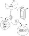
도 1은 본 발명의 실시 예에 따른 이어폰 및 휴대 단말기의 모습을 개략적으로 도시한 도면이다.1 is a schematic view illustrating an earphone and a portable terminal according to an embodiment of the present invention.
상기 도 1을 참조하면, 상기 휴대 단말기(100)는 일측에 이어폰(Earphone : 200)의 플러그(Plug : 220)가 삽입되는 이어잭(Earjack : 140)을 포함할 수 있다. 상기 휴대 단말기(100)는 이어잭(140)을 통해 상기 이어폰(200)에 오디오 신호를 송신하고, 상기 이어폰(200)으로부터 음성 신호를 수신할 수 있다. 또한, 상기 휴대 단말기(100)는 이어잭(140)을 통해 상기 이어폰(200)의 터치 입력부(210)를 통해 입력되는 조작 신호를 수신하고, 수신된 조작 신호에 대응하는 기능을 수행할 수 있다. 예를 들어, 상기 터치 입력부(210)를 통해 볼륨 업(Volume Up)을 요청하는 조작 신호가 입력되는 경우 상기 휴대 단말기(100)는 볼륨을 업시킬 수 있다.Referring to FIG. 1, the
상기 이어폰(200)은 마이크(Mike : 240), 스피커(Speaker : 230), 터치 입력부(210) 및 플러그(220)를 포함할 수 있다. 상기 마이크(240)는 음성 신호를 수신할 수 있다. 상기 스피커(230)는 음향 신호를 출력할 수 있다. 상기 스피커(230)는 우음향 신호를 출력하는 우스피커(231) 및 좌음향 신호를 출력하는 좌스피커(232)를 포함할 수 있다.The
상기 플러그(220)는 좌음향 단자(L), 우음향 단자(R), 접지단자(GND), 마이크 단자(MIC) 및 센싱단자(S)를 포함할 수 있다. 상기 좌음향 단자(L) 및 우음향 단자(R)는 휴대 단말기(100)로부터 좌음향 신호 및 우음향 신호를 각각 전송받을 수 있다. 상기 접지 단자(GND)는 휴대 단말기(100)의 접지와 연결된다. 또한, 도시하지는 않았지만, 상기 이어폰(200)이 FM 라디오 신호 및 방송 신호를 수신하는 안테나 역할을 수행하도록 구성된 경우 상기 접지 단자(GND)는 FM 라디오 또는 방송 신호를 휴대 단말기(100)에 전송할 수 있다. 상기 마이크 단자(MIC)는 이어폰(200)에 실장된 마이크(240)를 통해 입력되는 음성 신호를 휴대 단말기(100)에 전송할 수 있다. 상기 센싱 단자(S)는 상기 터치 입력부(210)와 연결되어, 상기 터치 입력부(210)의 터치(Touch), 롱터치(Long touch), 터치 이동(Touch Movement) 등에 따른 조작 신호를 휴대 단말기(100)에 전송할 수 있다. 한편, 상기 도 1에서는 종래 4극 이어폰의 마이크 단자를 분리하여 센싱 단자(S)를 추가한 형태로 플러그(220)를 도시하였지만 본 발명이 이에 한정되지는 않는다. 예를 들어, 상기 플러그(220)는 다양한 형태로 센싱 단자(S)를 추가할 수 있다.The
상기 터치 입력부(210)는 휴대 단말기(100)를 제어하기 위한 사용자의 조작 신호를 수신하기 위한 장치이다. 상기 조작 신호는 터치 신호가 될 수 있다. 상기 터치 입력부(210)는 터치 신호에 따라 다양한 기능을 제어하기 위하여 다수의 영역으로 구분될 수 있다. 이때, 사용자의 편의를 위하여 상기 터치 입력부(210)의 표면에는 터치 시 실행되는 기능을 나타내는 마크들(Marks : 1, 2, 3)이 인쇄될 수 있다. 예를 들어, 상기 도 1에 도시된 바와 같이 상기 터치 입력부(210)의 표면에는 볼륨 업키를 나타내는 제1마크(1), 볼륨 다운키를 나타내는 제2마크(2) 및 통화키를 나타내는 제3마크(3)가 인쇄될 수 있다. 하지만 본 발명이 이에 한정되지는 않는다. 예를 들어, 상기 마크는 제조사의 의도에 따라 다양한 형태로 인쇄될 수도 있다. 또는 상기 터치 입력부(210)의 표면에 마크가 없을 수도 있다. 또한, 상기 도 1에서는 상기 터치 입력부(210)가 3개의 영역으로 구분된 것으로 도시하였지만 본 발명이 이에 한정되지는 않는다. 즉, 상기 터치 입력부(210)는 제조사의 의도에 따라 하나 이상의 영역으로 구분될 수 있으며, 구분된 영역에 할당된 기능 역시 제조사의 의도에 따라 달라질 수 있다.The
또한, 상기 터치 입력부(210)는 터치 이동, 터치 속도에 따른 다양한 조작 신호를 휴대 단말기(100)에 제공할 수 있다. 예를 들어, 음악 파일 재생 중 사용자가 제1방향(제1마크에서 제3마크 방향)으로 기 설정된 기준 속도 미만으로 터치 이동하는 경우 상기 휴대 단말기(100)는 다음 곡을 재생하고, 제2방향(제3마크에서 제1마크 방향)으로 상기 기준 속도 미만으로 터치 이동하는 경우 이전 곡을 재생할 수 있다. 또는, 음악 파일 재생 중 사용자가 상기 제1방향으로 상기 기준 속도 이상으로 터치 이동하는 경우 상기 휴대 단말기(100)는 음악 파일의 재생 속도를 증가시키고, 상기 제2방향으로 상기 기준 속도 이상으로 터치 이동하는 경우 음악 파일의 재생 속도를 감소시킬 수 있다. 이러한, 상기 터치 입력부(210)는 저항막 방식으로 형성될 수 있다. 특히, 본 발명에 따른 상기 터치 입력부(210)는 한 장의 인듐 주석 산화물(ITO : Indum Tin Oxide) 필름만을 포함하여 일차원 좌표를 인식할 수 있다. 이는 터치 입력부(210)의 터치 입력을 처리하기 위한 별도의 IC가 필요없도록 회로를 단순화하여 비용을 절감하기 위함이다. 상기 터치 입력부(210)에 대한 상세한 설명은 도 2 및 도 3을 참조하여 후술하기로 한다.In addition, the
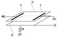
도 2는 본 발명의 실시 예에 따른 터치 입력부의 구조를 도시한 도면이고, 도 3은 본 발명의 실시 예에 따른 터치 입력부의 동작 원리를 설명하기 위한 등가 회로도를 도시한 도면이다.FIG. 2 is a diagram illustrating a structure of a touch input unit according to an embodiment of the present invention, and FIG. 3 is an equivalent circuit diagram illustrating the principle of operation of a touch input unit according to an embodiment of the present invention.
상기 도 1 내지 도 3을 참조하면, 상기 터치 입력부(210)는 저항막 층(21) 및 도전층(22)으로 구성될 수 있다.1 to 3, the
상기 저항막층(21)은 저항 성분이 코팅된 인듐 주석 산화(ITO) 필름으로 형성될 수 있다. 상기 저항막층(21)은 전원이 공급되는 양의 전극(Y+) 및 접지되는 음의 전극(Y-)를 양측 끝에 포함할 수 있다. 상기 양의 전극(Y+)은 상기 플러그(220)의 마이크 단자(MIC)와 연결된다. 즉, 상기 이어폰(200)이 휴대 단말기(100)에 장착되는 경우 상기 양의 전극(Y+)은 마이크 단자(MIC)를 통해 마이크 바이어스 전원(MIC_Bias)을 공급받을 수 있다.The
상기 도전층(22)은 전기가 통하는 금속막으로 형성될 수 있다. 상기 도전층(22)은 플러그(220)의 센싱 단자(S)와 연결되며, 터치 시 상기 저항막층(21)과 일측이 접촉될 수 있다. 상기 도전층(22)은 센싱 단자(S)의 플로팅(Floating)을 방지하기 위한 풀-다운 저장(Pull-down Resistor, Rb)과 연결될 수 있다.The
상기 터치 입력부(210)에 터치가 발생하지 않는 경우 상기 터치 입력부(210)는 상기 도 3의 (a)에 도시된 바와 같은 등가 회로로 표현될 수 있다. 즉, 양의 전극(Y+)에 휴대 단말기(100)로부터 공급되는 마이크 바이어스 전원(MIC_Bias)이 인가되고, 양의 전극(Y+)과 음의 전극(Y-) 사이에는 필름 저항(Ry)이 존재한다. 이때, 센싱 단자(S)에는 풀 다운 저항(Rb)에 의해 0V가 입력된다.If no touch occurs in the
한편, 터치가 발생하여 저항막층(21)과 도전층(22)의 일부가 접촉된 경우 상기 터치 입력부(210)는 상기 도 3의 (b)에 도시된 바와 같은 등가 회로로 표현될 수 있다. 즉, 터치 발생 시 상기 센싱 단자(S)에 인가되는 센싱 전압(Vs)은 아래 <식 1>과 같다.
Meanwhile, when a touch occurs and a part of the
Vs = Vmic_bias * {(Ry- // Rb) / (Ry- // Rb) + Ry+ + R1} (식 1)
Vs = Vmic_bias * {(Ry- // Rb) / (Ry- // Rb) + Ry + + R1}
상기 <식 1>에서, Vmic_bias는 휴대 단말기(100)로부터 인가되는 마이크 바이어스 전압이다. 상기 R1은 풀업(Pull-up) 저항으로, 설명의 편의을 위하여 상기 도 3에 도시 하였으나 휴대 단말기(100)에 실장되는 부품이다. 상기 Ry+는 양의 전극(Y+)과 터치 지점 사이의 저항이고, Ry-는 터치 지점과 음의 전극(Y-) 사이의 저항이다. 즉, Ry+ 및 Ry-의 값은 터치 위치에 따라 달라진다. 상기 (Ry- // Rb)는 저항 Ry- 및 저항 Rb의 병렬 합성 저항값을 의미한다. 상기 병렬 합성 저항값을 산출하는 방법은 당업자에게 자명하며, 공지된 기술이므로 상세한 설명을 생략하기로 한다. 상기 센싱 전압(Vs)은 플러그(220)의 센싱 단자(S)를 통해 휴대 단말기(100)에 전송되고, 상기 휴대 단말기(100)는 전송된 센싱 전압(Vs)을 통해 터치 위치를 인식할 수 있다.In Equation (1), Vmic_bias is a microphone bias voltage applied from the
도 4는 본 발명의 실시 예에 따른 이어폰 및 휴대 단말기의 구성을 개략적으로 도시한 블록도이다.4 is a block diagram schematically illustrating a configuration of an earphone and a portable terminal according to an embodiment of the present invention.
상기 도 1 내지 도 4를 참조하면, 상기 이어폰(200)은 터치 입력부(210), 플러그(220), 스피커(230) 및 마이크(240)를 포함하고, 상기 휴대 단말기(100)는 오디오 처리부(160), 이어잭(140), 표시부(130), 저장부(120) 및 제어부(110)를 포함할 수 있다.1 to 4, the
상기 터치 입력부(210)는 사용자의 제스처(터치, 롱터치, 터치 이동 방향, 터치 이동 속도 등)에 따른 조작 신호를 상기 휴대 단말기(100)에 전송할 수 있다. 이러한 상기 터치 입력부(210)에 대한 상세한 설명은 도 1 내지 도 3에서 상술하였으므로 생략하기로 한다. 상기 도 4에서는 터치된 상태를 기준으로 도시하였다. 상기 스피커(230)는 상기 휴대 단말기(100)로부터 전송되는 음향 신호를 출력할 수 있다. 상기 스피커(230)는 상기 플러그(220)의 우음향 단자(R)와 연결되어 우음향 신호를 출력하는 우스피커(231) 및 상기 플러그(220)의 좌음향 단자(L)와 연결되어 좌음향 신호를 출력하는 좌스피커(232)를 포함할 수 있다. 상기 마이크(240)는 음성 신호를 입력받을 수 있다. 상기 입력된 음성 신호는 플러그(220)의 마이크 단자(MIC)를 통해 휴대 단말기(100)에 전송될 수 있다. 상기 마이크(240)의 양단자(+)는 상기 터치 입력부(210)의 양의 전극(Y+)과 연결될 수 있다.The
상기 플러그(220)는 휴대 단말기(100)와의 인터페이스를 위한 장치이다. 상기 플러그(220)는 마이크 단자(MIC), 접지 단자(GND), 우음향 단자(R), 좌음향 단자(L) 및 센싱 단자(S)를 포함할 수 있다. 이러한 상기 플러그(220)에 대한 설명은 상기 도 1에서 상술하였으므로 생략하기로 한다.The
상기 이어잭(140)은 상기 이어폰(200)과의 인터페이스를 위한 장치로, 이어폰(200)의 플러그(220)와 같이 마이크 단자(MIC), 접지 단자(GND), 우음향 단자(R), 좌음향 단자(L) 및 센싱 단자(S)를 포함하고, 이어폰(200)의 장착 여부를 검출하기 위한 검출 단자(DET)를 더 포함할 수 있다.The
상기 이어잭(140)의 센싱 단자(S)는 제1아날로그 디지털 변환부(ADC1)와 연결되고, 상기 이어잭(140)의 접지 단자(GND)는 접지되고, 상기 이어잭(140)의 우음향 단자(R)는 오디오 처리부(160)의 우음향 출력 단자(R)와 연결되며, 상기 이어잭(140)의 좌음향 단자(L)는 오디오 처리부(160)의 좌음향 출력 단자(L)와 연결될 수 있다. 한편, 상기 이어폰(200)이 FM 라디오 신호 및 방송 신호를 수신하는 안테나 역할을 수행하도록 구성한 경우 상기 이어잭(140)의 접지 단자(GND)는 방송 신호를 수신하여 재생하는 방송 수신부(미도시) 또는 FM 라디오 재생부(미도시)에 선택적으로 연결될 수 있다.The sensing terminal S of the
상기 검출 단자(DET)는 풀업 저항인 제2저항(R2)와 연결되며, 이어폰(200) 미장착 시 오픈(Open) 상태가 되고, 이어폰(200) 장착 시 이어폰(200)의 접지 단자(GND)와 연결될 수 있다. 상기 이어잭(140)의 마이크 단자(MIC)는 이어폰(200)의 마이크(240) 동작을 위한 마이크 바이어스 전원(MIC_Bias)이 연결되어 있다. 상기 마이크 바이어스 전원(MIC_Bias)과 마이크 단자(MIC) 사이에는 풀업(Pull-up) 저항인 제1저항(R1)이 존재한다. 또한, 상기 이어잭(140)의 마이크 단자(MIC)는 후술하는 제2아날로그 디지털 변환부(ADC2) 및 오디오 처리부(160)의 마이크 입력 단자(MIC)와 연결될 수 있다.The detection terminal DET is connected to a second resistor R2 which is a pull-up resistor and is opened when the
상기 오디오 처리부(160)는 오디오 신호를 송수신하여 인코딩 및 디코딩을 수행하는 음향 부품으로 형성될 수 있다. 이러한 상기 오디오 처리부(160)는 코덱(Codec) 및 오디오 앰프(Amp) 등을 포함할 수 있다. 상기 오디오 처리부(160)는 휴대 단말기(100)에 실장된 마이크(161) 및 스피커(162)와 연결되며, 상기 휴대 단말기의 마이크(161) 또는 이어폰(200)의 마이크(240)로부터 입력되는 아날로그 음성 신호를 디지털 음성 신호로 변환하고 데이터화하여 상기 제어부(110)로 전송하고, 상기 제어부(110)로부터 입력되는 디지털 음성 신호를 아날로그 음성 신호로 변환하여 휴대 단말기(100)의 스피커(162) 또는 이어폰(200)의 스피커(230)를 통해 출력할 수 있다. 또한, 상기 오디오 처리부(160)는 휴대 단말기(100)에서 발생하는 다양한 오디오 신호를 휴대 단말기(100)의 스피커(162) 또는 이어폰(200)의 스피커(230)를 통해 출력할 수 있다. 예를 들어, 상기 오디오 처리부(160)는 MP3 파일 재생, 동영상 파일 재생 등에 따른 오디오 신호를 휴대 단말기(100)의 스피커(162) 또는 이어폰(200)의 스피커(230)를 통해 출력할 수 있다. 이를 위하여 상기 오디오 처리부(160)는 마이크 입력 단자(MIC), 우음향 출력 단자(R) 및 좌음향 출력 단자(L)를 포함할 수 있다.The
상기 표시부(130)는 휴대 단말기(100)의 각종 메뉴를 비롯하여 사용자가 입력한 정보 또는 사용자에게 제공하기 위한 정보를 표시한다. 예를 들어, 상기 표시부(130)는 휴대 단말기(100)의 이용에 따른 다양한 화면 예컨대 대기 화면, 메시지 작성 화면, 통화 화면 등을 제공할 수 있다. 특히, 본 발명에 따른 표시부(130)는 이어폰 (200) 장착 시 이어폰(200)이 장착되었음을 알리는 아이콘을 배터리 잔량, 수신 강도, 알람 설정 상태 등을 알리는 인디케이터(Indicator) 영역에 표시할 수 있다. 상기 표시부(130)는 터치 입력부(210)로부터 입력되는 조작 신호에 대응하는 기능을 수행하는 화면을 출력할 수 있다. 예를 들어, 상기 터치 입력부(210)로부터 통화 요청 신호가 입력되는 경우 상기 표시부(130)는 통화 요청 화면을 출력할 수 있다. 상기 표시부(130)는 액정 표시 장치(Liquid Crystal Display), OLED(Organic Light Emitted Diode), AMOLED(Active Matrix Organic Light Emitted Diode) 등으로 형성될 수 있다. 한편, 상기 표시부(130)가 터치스크린으로 형성되는 경우 상기 표시부(130)는 입력부(미도시)의 기능을 수행할 수도 있다.The
상기 저장부(120)는 본 발명의 실시 예에 따른 기능 동작에 필요한 프로그램을 비롯하여, 사용자 데이터 등을 저장할 수 있다. 예를 들어, 상기 저장부(120)는 휴대 단말기(100)의 전반적인 동작을 제어하는 프로그램 및 휴대 단말기(100)를 부팅시키는 운영체제(OS, Operating System), 휴대 단말기(100)의 기타 옵션(Options) 기능 예컨대, 카메라 기능, 소리 재생 기능, 이미지 또는 동영상 재생 기능, 근거리 무선 통신 기능 등에 필요한 응용 프로그램 등을 저장할 수 있다. 또한, 상기 저장부(120)는 휴대 단말기(100)의 사용에 따라 발생하는 사용자 데이터 예컨대 문자 메시지, 게임 파일, 음악 파일, 영화 파일 등을 저장할 수 있다. 특히, 본 발명에 따른 저장부(120)는 터치 입력부(210)로부터 입력되는 조작 신호와 특정 기능을 매핑한 매핑 테이블(Mapping table)을 저장할 수 있다. 상기 매핑 테이블은 아래 <표 1>가 같이 구성될 수 있다.The

상기 <표 1>을 참조하면, 매핑 테이블은 터치, 터치 이동에 따른 조작 신호와 특정 기능이 매핑되어 있다. 상기 조작 신호에 매핑된 기능은 휴대 단말기(100)의 상태에 따라 달라질 수 있다. 예를 들어, 대기 상태에서 0 V 초과 ~ 0.7 V 이하의 전압이 입력되는 경우 통화 요청 기능이 수행되고, 음악 재생 프로그램이 실행된 상태에서 0 V 초과 ~ 0.7 V 이하의 전압이 입력되는 경우 음악 재생/중지 기능이 수행될 수 있다. 한편, 상기 <표 1>은 일예를 도시한 것으로 본 발명이 이에 한정되지 않는다. 예를 들어, 상기 <표 1>에서는 터치를 3 단계로 구분하였지만 설계자의 의도에 따라 하나 이상으로 다양하게 설정할 수 있다. 또한, 상기 매핑 테이블이 대기 상태, 음악 재생 및 통화 중 상태를 포함하는 것으로 도시하였지만, 상기 매핑 테이블은 방송 재생 상태, 게임 상태 등과 같은 다양한 상태를 포함할 수도 있다. 한편, 상기 저장부(120)는 매핑 테이블을 사용자가 변경할 수 있는 메뉴를 제공할 수도 있다. 상기 메뉴를 통해 사용자는 조작 신호에 매핑된 기능을 변경하거나, 조작 신호를 추가 또는 삭제할 수 있다.Referring to Table 1, the mapping table is mapped with a specific function and an operation signal according to touch and touch movement. The function mapped to the operation signal may vary depending on the state of the
상기 제어부(110)는 휴대 단말기(100)의 전반적인 동작 및 휴대 단말기(100)의 내부 블록들 간 신호 흐름을 제어할 수 있다. 특히, 본 발명에 따른 제어부(110)는 이어잭(140)의 검출 단자(DET)와 연결되며, 이어폰(200)의 장착 여부를 감지하는 이어폰 검출 단자(Ear_detect), 상기 이어잭(140)의 센싱 단자(S)와 연결되며, 상기 터치 입력부(210)의 조작 신호를 입력받는 제1아날로그 디지털 변환부(ADC1) 및 상기 이어잭(140)의 마이크 단자(MIC)와 연결되는 제2아날로그 디지털 변환부(ADC2)를 포함할 수 있다.The
상기 이어폰 검출 단자(Ear_detect)는 GPIO 단자로 형성될 수 있다. 상기 이어폰 검출 단자(Ear_detect)는 풀업 저항인 제2저항(R2)이 연결될 수 있다. 즉, 상기 제어부(110)는 전원(VDD)에 의하여 이어폰 검출 단자(Ear_detect)에 하이(High) 신호(예컨대 3V)가 입력되는 경우 이어폰(200)이 미장착된 것으로 판단하고, 상기 이어잭(140)의 검출 단자(DET)가 이어폰(200)의 접지단자(GND)와 연결되어 이어폰 검출 단자(Ear_detect)에 로우(Low) 신호(예컨대 0 V)가 입력되는 경우 이어폰(200)이 장착된 것으로 판단할 수 있다.The earphone detection terminal Ear_detect may be formed of a GPIO terminal. The earphone detection terminal (Ear_detect) may be connected to a second resistor (R2) which is a pullup resistor. That is, when the
상기 제1아날로그 디지털 변환부(ADC1)는 아날로그 신호를 디지털 신호로 변환하는 장치로, 상기 이어잭(140)의 센싱 단자(S)와 연결되어 이어폰(200)으로부터 입력되는 아날로그 전압을 디지털 신호로 변환할 수 있다. 상기 제어부(110)는 상기 제1아날로그 디지털 변환부(ADC1)로부터 입력되는 디지털 신호를 통해 터치 지점을 인식하고, 터치 지점에 매핑된 기능을 수행할 수 있다. 또한, 상기 제어부(110)는 터치 지점이 연속적으로 변경되는 경우 터치 이동으로 판단할 수 있다. 이때, 제어부(110)는 터치 이동 방향 및 터치에서 터치 해제까지의 시간을 측정하여 터치 이동 속도를 확인할 수 있다. 이를 통해, 상기 제어부(110)는 상기 <표 1>에서 상술한 바와 같은 다양한 조작 신호를 구분하고, 매핑된 기능을 수행할 수 있다. 상세하게는, 상기 제어부(110)는 터치 발생시 좌표 이동(전압 변화)없이 유지되는 시간을 측정하고, 상기 터치가 기 설정된 제1기준 시간 이상 유지되는 경우 롱터치로 인식할 수 있다. 또한, 상기 제어부(110)는 터치 이동을 제1방향과 제2방향으로 구분할 수 있다. 예를 들어, 상기 제어부(110)는 상기 제1아날로그 디지털 변환부(ADC1)에 입력되는 전압이 점점 커지는 경우 상기 제1방향으로 인식하고, 상기 제1아날로그 디지털 변환부(ADC1)에 입력되는 전압이 점점 작아지는 경우 상기 제2방향으로 인식할 수 있다. 또한, 상기 제어부(110)는 터치 시부터 터치 해제까지의 시간을 측정하고, 측정된 시간이 기 설정된 제2기준 시간 이상인지 확인할 수 있다. 상기 제어부(110)는 측정된 시간이 상기 제2기준 시간 이하인 경우 상기 터치 속도가 기 설정된 기준 속도 이상인 것으로 판단하고, 측정된 시간이 상기 제2기준 시간을 초과하는 경우 상기 터치 속도가 상기 기준 속도 미만인 것으로 판단할 수 있다.The first analog-to-digital converter (ADC1) converts an analog signal into a digital signal and is connected to a sensing terminal (S) of the ear jack (140) to convert an analog voltage input from the earphone Can be converted. The
상기 제2아날로그 디지털 변환부(ADC2)는 이어잭(140)의 마이크 단자(MIC)와 연결되어 종래의 버튼식 키 조작부를 가지는 4극 이어폰의 조작 신호를 구분할 수 있다. 이는 공지된 기술로 상세한 설명은 생략하기로 한다. 즉, 상기 제2아날로그 디지털 변환부(ADC2)는 종래의 4극 이어폰과 휴대 단말기(100)의 호환성을 위한 것으로, 생략될 수도 있다.The second analog-to-digital converter (ADC2) is connected to a microphone (MIC) of the
한편, 상기 도 4에서 도시하지 않았지만 본 발명에 따른 휴대 단말기(100)는 이미지 또는 동영상 촬영을 위한 카메라 모듈, 방송 수신을 위한 방송 수신 모듈, MP3 모듈과 같은 디지털 음원 재생 모듈, 근거리 무선 통신을 위한 근거리 무선 통신 모듈 및 근접 센싱을 위한 근접 센서 모듈 등 부가 기능을 제공하기 위한 구성 요소들을 선택적으로 더 포함할 수 있다. 이러한 구성 요소들은 디지털 기기의 컨버전스(convergence) 추세에 따라 변형이 매우 다양하여 모두 열거할 수는 없으나, 본 발명에 따른 휴대 단말기(100)는 상기 언급된 구성 요소들과 동등한 수준의 구성 요소들을 더 포함할 수 있다.4, the
이상에서는 본 발명의 실시 예에 따른 터치 입력부를 구비하는 이어폰 및 이를 이용하는 휴대 단말기에 대하여 본 명세서 및 도면을 통해 바람직한 실시 예들에 대하여 설명하였으며, 비록 특정 용어들이 사용되었으나 이는 단지 본 발명의 기술 내용을 쉽게 설명하고 발명의 이해를 돕기 위해 일반적인 의미에서 사용된 것일 뿐, 본 발명이 전술한 실시 예에 한정되는 것은 아니다. 즉, 본 발명의 기술적 사상에 바탕을 둔 다양한 실시 예가 가능함은 본 발명이 속하는 기술 분야에서 통상의 지식을 가진 자에게 자명한 것이다.While the present invention has been particularly shown and described with reference to exemplary embodiments thereof, it is to be understood that the invention is not limited to the disclosed exemplary embodiments. It is to be understood that the present invention is not limited to the above-described embodiments. That is, it is apparent to those skilled in the art that various embodiments based on the technical idea of the present invention are possible.
100 : 휴대 단말기 110 : 제어부
120 : 저장부 130 : 표시부
140 : 이어잭 160 : 오디오 처리부
200 : 이어폰 210 : 터치 입력부
220 : 플러그 230 : 이어폰 스피커
240 : 이어폰 마이크100: portable terminal 110:
120: storage unit 130: display unit
140: ear jack 160: audio processor
200: earphone 210: touch input unit
220: Plug 230: Earphone speaker
240: earphone microphone
Claims (15)
Translated fromKorean좌음향 신호를 출력하는 좌스피커;
우음향 신호를 출력하는 우스피커;
일차원 좌표를 인식하는 터치 입력부; 및
상기 터치 입력부의 조작 신호를 전송하기 위한 센싱 단자, 상기 마이크와 연결되며 상기 마이크 구동을 위한 바이어스 전압을 공급하는 마이크 단자, 좌음향 신호를 출력하는 좌스피커와 연결되는 좌음향 단자, 우음향 신호를 출력하는 우스피커와 연결되는 우음향 단자 및 접지 단자를 포함하고,
상기 터치 입력부는,
저항 성분으로 코팅된 저항막층; 및
상기 센싱 단자와 연결되며, 터치 입력 시 상기 저항막층의 적어도 일부와 접촉하는 도전층을 포함하는 플러그를 포함하는 것을 특징으로 하는 이어폰.A microphone for receiving a voice signal;
A left speaker for outputting a left acoustic signal;
A right speaker for outputting a right acoustic signal;
A touch input unit for recognizing one-dimensional coordinates; And
A sensing terminal for transmitting an operation signal of the touch input unit, a microphone terminal connected to the microphone for supplying a bias voltage for driving the microphone, a left acoustic terminal connected to a left speaker for outputting a left acoustic signal, A right acoustic terminal and a ground terminal connected to the right speaker for output,
The touch input unit includes:
A resistive film layer coated with a resistive component; And
And a conductive layer connected to the sensing terminal, the conductive layer being in contact with at least a part of the resistance film layer upon touch input.
상기 저항막 층은
일측 끝에 위치하며, 상기 마이크 단자와 연결되는 양의 전극; 및
상기 양의 전극 맞은 편 끝에 위치하며, 접지되는 음의 전극을 포함하는 것을 특징으로 하는 이어폰.The method according to claim 1,
The resistive film layer
A positive electrode which is located at one end and is connected to the microphone terminal; And
And a negative electrode which is located at the opposite end of the positive electrode and is grounded.
상기 도전층과 연결되며, 상기 센싱단자의 플로팅(Floating)을 방지하기 위한 풀-다운 저항(Pull-down Resistor)을 더 포함하는 것을 특징으로 하는 이어폰.The method according to claim 1,
Further comprising a pull-down resistor connected to the conductive layer for preventing floating of the sensing terminal.
상기 터치 입력부는
표면에 터치 시 실행되는 기능을 나타내는 적어도 하나의 마크가 인쇄된 것을 특징으로 하는 이어폰.The method according to claim 1,
The touch input unit
Wherein at least one mark indicative of a function to be executed upon touching the surface is printed.
상기 조작 신호는
터치 신호, 롱터치 신호, 기설정된 기준 속도 미만의 제1방향 터치 이동 신호, 상기 기준 속도 미만의 제2방향 터치 이동 신호, 상기 기준 속도 이상의 제1방향 터치 이동 신호 및 상기 기준 속도 이상의 제2방향 터치 이동 신호를 포함하는 것을 특징으로 하는 이어폰.The method according to claim 1,
The operation signal
A first direction touch movement signal that is less than a predetermined reference speed, a second direction touch movement signal that is less than the reference speed, a first direction touch movement signal that is faster than the reference speed, and a second direction And a touch movement signal.
일차원 좌표를 인식하는 터치 입력부를 포함하는 이어폰이 삽입되어 상기 터치 입력부로부터 조작 신호를 수신하는 센싱 단자, 상기 이어폰 삽입 시 상기 이어폰의 접지 단자와 연결되는 검출 단자, 상기 이어폰의 음성 신호가 입력되며 마이크 바이어스 전원이 연결되는 마이크 단자, 접지가 연결되는 접지 단자, 우음향 신호를 상기 이어폰에 전송하기 위한 우음향 단자 및 좌음향 신호를 상기 이어폰에 전송하기 위한 좌음향 단자를 포함하는 이어잭; 및
상기 이어폰의 삽입 여부를 검출하며, 상기 터치 입력부로부터 조작 신호를 입력받아 상기 조작 신호에 대응하는 기능을 수행하는 제어부를 포함하고,
상기 터치 입력부는,
저항 성분으로 코팅된 저항막층; 및
상기 센싱 단자와 전기적으로 연결되며, 터치 입력 시 상기 저항막층의 적어도 일부와 접촉하는 도전층을 포함하는 것을 특징으로 하는 휴대 단말기.In a portable terminal,
A sensing terminal for receiving an operation signal from the touch input unit when an earphone including a touch input unit for recognizing a one-dimensional coordinate is inserted; a detection terminal connected to a ground terminal of the earphone when the earphone is inserted; An ear jack including a microphone terminal to which a bias power is connected, a ground terminal to which a ground is connected, a right acoustic terminal for transmitting a right acoustic signal to the earphone, and a left acoustic terminal for transmitting a left acoustic signal to the earphone; And
And a controller for detecting whether or not the earphone is inserted and receiving a manipulation signal from the touch input unit and performing a function corresponding to the manipulation signal,
The touch input unit includes:
A resistive film layer coated with a resistive component; And
And a conductive layer electrically connected to the sensing terminal and contacting at least a part of the resistance film layer when a touch is input.
상기 제어부는
상기 이어잭의 검출 단자와 연결되며, 풀업 저항이 연결되는 이어폰 검출 단자를 포함하는 것을 특징으로 하는 휴대 단말기.8. The method of claim 7,
The control unit
And an earphone detection terminal connected to a detection terminal of the ear jack and connected with a pull-up resistor.
상기 제어부는
상기 이어잭의 센싱 단자와 연결되는 제1아날로그 디지털 변환부를 포함하는 것을 특징으로 하는 휴대 단말기.8. The method of claim 7,
The control unit
And a first analog-to-digital converter connected to the sensing terminal of the ear jack.
상기 제어부는
상기 이어잭의 마이크 단자와 연결되는 제2아날로그 디지털 변환부를 더 포함하는 것을 특징으로 하는 휴대 단말기.8. The method of claim 7,
The control unit
And a second analog-to-digital converter connected to the microphone jack of the ear jack.
상기 제어부는
터치가 기 설정된 제1기준 시간 이상 유지되는 경우 롱터치로 인식하는 것을 특징으로 하는 휴대 단말기.8. The method of claim 7,
The control unit
And recognizes the touch as a long touch when the touch is maintained for a predetermined first reference time or more.
상기 제어부는
상기 제1아날로그 디지털 변환부에 입력되는 전압의 변화를 통해 터치 이동을 제1방향과 제2방향으로 구분하는 것을 특징으로 하는 휴대 단말기.10. The method of claim 9,
The control unit
Wherein the controller divides the touch movement into a first direction and a second direction through a change in voltage input to the first analog-to-digital converter.
상기 제어부는
터치 시부터 터치 해제까지의 시간을 측정하여 상기 터치 속도가 기 설정된 기준 속도 이상인지 확인하는 것을 특징으로 하는 휴대 단말기.8. The method of claim 7,
The control unit
Wherein the controller determines whether the touch speed is equal to or greater than a preset reference speed by measuring a time from a touch to a touch release.
상기 조작 신호와 특정 기능을 매핑한 매핑 테이블을 저장하는 저장부를 더 포함하는 것을 특징으로 하는 휴대 단말기.8. The method of claim 7,
Further comprising a storage unit for storing a mapping table in which the operation signal is mapped to a specific function.
상기 저장부는
상기 매핑 테이블을 변경할 수 있는 메뉴를 더 저장하는 것을 특징으로 하는 휴대 단말기.15. The method of claim 14,
The storage unit
And further stores a menu for changing the mapping table.
Priority Applications (3)
| Application Number | Priority Date | Filing Date | Title |
|---|---|---|---|
| KR1020110018587AKR101831644B1 (en) | 2011-03-02 | 2011-03-02 | Earphone having the touch input unit and a portable terminal using the same |
| US13/408,104US9031252B2 (en) | 2011-03-02 | 2012-02-29 | Headphones with touch input unit, and mobile device allowing for the connection to the headphones |
| EP12157672.2AEP2495989B1 (en) | 2011-03-02 | 2012-03-01 | Headphones with touch input unit, and mobile device allowing for the connection to the headphones |
Applications Claiming Priority (1)
| Application Number | Priority Date | Filing Date | Title |
|---|---|---|---|
| KR1020110018587AKR101831644B1 (en) | 2011-03-02 | 2011-03-02 | Earphone having the touch input unit and a portable terminal using the same |
Publications (2)
| Publication Number | Publication Date |
|---|---|
| KR20120100007A KR20120100007A (en) | 2012-09-12 |
| KR101831644B1true KR101831644B1 (en) | 2018-02-23 |
Family
ID=45757321
Family Applications (1)
| Application Number | Title | Priority Date | Filing Date |
|---|---|---|---|
| KR1020110018587AExpired - Fee RelatedKR101831644B1 (en) | 2011-03-02 | 2011-03-02 | Earphone having the touch input unit and a portable terminal using the same |
Country Status (3)
| Country | Link |
|---|---|
| US (1) | US9031252B2 (en) |
| EP (1) | EP2495989B1 (en) |
| KR (1) | KR101831644B1 (en) |
Families Citing this family (8)
| Publication number | Priority date | Publication date | Assignee | Title |
|---|---|---|---|---|
| US9185536B1 (en) | 2011-09-16 | 2015-11-10 | Peter R. Johnson | Apparatus and method for obtaining inconspicuous user input on a mobile device |
| US9161193B1 (en) | 2014-06-04 | 2015-10-13 | Grandios Technologies, Llc | Advanced telephone management |
| CN104577334B (en)* | 2015-02-11 | 2017-07-21 | 小米科技有限责任公司 | Anneta module and mobile terminal |
| KR101703245B1 (en)* | 2015-02-16 | 2017-03-06 | (주) 아프로윈 | Electroacoustic tranducer |
| CN105163224A (en)* | 2015-10-21 | 2015-12-16 | 歌尔声学股份有限公司 | Line-controlled earphone control method and system, and line-controlled earphone |
| JP2019506776A (en) | 2015-12-30 | 2019-03-07 | シェンジェン ロイオル テクノロジーズ カンパニー リミテッドShenzhen Royole Technologies Co., Ltd. | Head mounted display device and control method thereof |
| JP2020166641A (en)* | 2019-03-29 | 2020-10-08 | ソニー株式会社 | Information processing equipment, information processing method, and program |
| CN114125633A (en)* | 2021-11-26 | 2022-03-01 | 深圳市逸音科技有限公司 | A headphone touch method and device for active noise reduction |
Citations (2)
| Publication number | Priority date | Publication date | Assignee | Title |
|---|---|---|---|---|
| US20060215847A1 (en)* | 2003-04-18 | 2006-09-28 | Gerrit Hollemans | Personal audio system with earpiece remote controller |
| KR100871260B1 (en)* | 2002-08-24 | 2008-11-28 | 삼성전자주식회사 | Ear jack plug connection detection device |
Family Cites Families (8)
| Publication number | Priority date | Publication date | Assignee | Title |
|---|---|---|---|---|
| US4764717A (en)* | 1986-10-27 | 1988-08-16 | Utah Scientific Advanced Development Center, Inc. | Touch-sensitive potentiometer for operator control panel |
| JP2001093374A (en) | 1999-09-27 | 2001-04-06 | Sony Corp | Switch and electronics having switch |
| JP2006033150A (en) | 2004-07-13 | 2006-02-02 | Mitsumi Electric Co Ltd | Headset device |
| KR101259477B1 (en) | 2006-08-07 | 2013-05-06 | 삼성전자주식회사 | Headset having remote control function |
| US20080130910A1 (en) | 2006-11-30 | 2008-06-05 | Motorola, Inc. | Gestural user interface devices and methods for an accessory to a wireless communication device |
| US20090124286A1 (en) | 2007-11-12 | 2009-05-14 | Sony Ericsson Mobile Communications Ab | Portable hands-free device with sensor |
| KR20090055359A (en)* | 2007-11-28 | 2009-06-02 | 삼성전자주식회사 | 4 pole earphone and 5 pole earphone compatible circuit and method and mobile terminal using the same |
| US8600080B2 (en) | 2008-01-14 | 2013-12-03 | Apple Inc. | Methods for communicating with electronic device accessories |
- 2011
- 2011-03-02KRKR1020110018587Apatent/KR101831644B1/ennot_activeExpired - Fee Related
- 2012
- 2012-02-29USUS13/408,104patent/US9031252B2/ennot_activeExpired - Fee Related
- 2012-03-01EPEP12157672.2Apatent/EP2495989B1/enactiveActive
Patent Citations (2)
| Publication number | Priority date | Publication date | Assignee | Title |
|---|---|---|---|---|
| KR100871260B1 (en)* | 2002-08-24 | 2008-11-28 | 삼성전자주식회사 | Ear jack plug connection detection device |
| US20060215847A1 (en)* | 2003-04-18 | 2006-09-28 | Gerrit Hollemans | Personal audio system with earpiece remote controller |
Also Published As
| Publication number | Publication date |
|---|---|
| US9031252B2 (en) | 2015-05-12 |
| EP2495989B1 (en) | 2019-05-22 |
| KR20120100007A (en) | 2012-09-12 |
| EP2495989A3 (en) | 2015-01-21 |
| US20120224730A1 (en) | 2012-09-06 |
| EP2495989A2 (en) | 2012-09-05 |
Similar Documents
| Publication | Publication Date | Title |
|---|---|---|
| KR101831644B1 (en) | Earphone having the touch input unit and a portable terminal using the same | |
| KR102067019B1 (en) | Apparatus and method for controlling charging path of mobile terminal | |
| US9226063B2 (en) | Method and apparatus for recognizing accessory of portable terminal | |
| JP6184684B2 (en) | Earphone connection detection system and terminal supporting the same | |
| US9927938B2 (en) | Coordinate measuring apparatus for measuring input position of a touch and a coordinate indicating apparatus and method thereof | |
| US20100131749A1 (en) | Apparatus and method for controlling operating mode of mobile terminal | |
| US20170270897A1 (en) | Earphone system for mobile device and method for operating the same | |
| CN107613146B (en) | A volume adjustment method, device and mobile terminal | |
| KR20140092722A (en) | Mobile apparatus displaying screen according to type of cover comprising of transparent-section and control method thereof | |
| US11431181B2 (en) | Wireless sound output device with charging function | |
| JP2012257129A (en) | Portable terminal, backlight control program and backlight control method | |
| CN108319445A (en) | A kind of audio playing method and mobile terminal | |
| CN108924358A (en) | Proximity sensor control method, electronic device, and computer-readable storage medium | |
| TW201511540A (en) | Apparatus and method of showing progress bar | |
| CN107786751A (en) | A kind of method for broadcasting multimedia file and mobile terminal | |
| CN111459447B (en) | Volume adjustment display method and electronic equipment | |
| CN110851107A (en) | A kind of control method of electronic equipment and electronic equipment | |
| CN108848239B (en) | Breathing light components and electronic devices | |
| CN105611445B (en) | Recognition methods, device and the mobile terminal of self-shooting bar and self-shooting bar | |
| US9977528B2 (en) | Electronic device having touch sensor | |
| CN108900942B (en) | A playback control method and electronic device | |
| WO2020221043A1 (en) | Charge control circuit, terminal device and data line | |
| CN108259647B (en) | Photoreceptor assembly and electronic device having the same | |
| US10104462B2 (en) | Sound output unit | |
| CN115454308A (en) | Floating window display method, device and terminal equipment |
Legal Events
| Date | Code | Title | Description |
|---|---|---|---|
| PA0109 | Patent application | St.27 status event code:A-0-1-A10-A12-nap-PA0109 | |
| R18-X000 | Changes to party contact information recorded | St.27 status event code:A-3-3-R10-R18-oth-X000 | |
| PG1501 | Laying open of application | St.27 status event code:A-1-1-Q10-Q12-nap-PG1501 | |
| A201 | Request for examination | ||
| PA0201 | Request for examination | St.27 status event code:A-1-2-D10-D11-exm-PA0201 | |
| P22-X000 | Classification modified | St.27 status event code:A-2-2-P10-P22-nap-X000 | |
| P22-X000 | Classification modified | St.27 status event code:A-2-2-P10-P22-nap-X000 | |
| D13-X000 | Search requested | St.27 status event code:A-1-2-D10-D13-srh-X000 | |
| D14-X000 | Search report completed | St.27 status event code:A-1-2-D10-D14-srh-X000 | |
| E902 | Notification of reason for refusal | ||
| PE0902 | Notice of grounds for rejection | St.27 status event code:A-1-2-D10-D21-exm-PE0902 | |
| E13-X000 | Pre-grant limitation requested | St.27 status event code:A-2-3-E10-E13-lim-X000 | |
| P11-X000 | Amendment of application requested | St.27 status event code:A-2-2-P10-P11-nap-X000 | |
| P13-X000 | Application amended | St.27 status event code:A-2-2-P10-P13-nap-X000 | |
| E701 | Decision to grant or registration of patent right | ||
| PE0701 | Decision of registration | St.27 status event code:A-1-2-D10-D22-exm-PE0701 | |
| GRNT | Written decision to grant | ||
| PR0701 | Registration of establishment | St.27 status event code:A-2-4-F10-F11-exm-PR0701 | |
| PR1002 | Payment of registration fee | St.27 status event code:A-2-2-U10-U11-oth-PR1002 Fee payment year number:1 | |
| PG1601 | Publication of registration | St.27 status event code:A-4-4-Q10-Q13-nap-PG1601 | |
| PR1001 | Payment of annual fee | St.27 status event code:A-4-4-U10-U11-oth-PR1001 Fee payment year number:4 | |
| PC1903 | Unpaid annual fee | St.27 status event code:A-4-4-U10-U13-oth-PC1903 Not in force date:20220220 Payment event data comment text:Termination Category : DEFAULT_OF_REGISTRATION_FEE | |
| PC1903 | Unpaid annual fee | St.27 status event code:N-4-6-H10-H13-oth-PC1903 Ip right cessation event data comment text:Termination Category : DEFAULT_OF_REGISTRATION_FEE Not in force date:20220220 |