KR101830960B1 - Detecting apparatas and method for having integrated a nfc antenna and non-contact charging coil in a user terminal - Google Patents
Detecting apparatas and method for having integrated a nfc antenna and non-contact charging coil in a user terminalDownload PDFInfo
- Publication number
- KR101830960B1 KR101830960B1KR1020110082050AKR20110082050AKR101830960B1KR 101830960 B1KR101830960 B1KR 101830960B1KR 1020110082050 AKR1020110082050 AKR 1020110082050AKR 20110082050 AKR20110082050 AKR 20110082050AKR 101830960 B1KR101830960 B1KR 101830960B1
- Authority
- KR
- South Korea
- Prior art keywords
- value
- antenna
- switch
- voltage
- transceiver
- Prior art date
- Legal status (The legal status is an assumption and is not a legal conclusion. Google has not performed a legal analysis and makes no representation as to the accuracy of the status listed.)
- Expired - Fee Related
Links
Images


Classifications
- H—ELECTRICITY
- H02—GENERATION; CONVERSION OR DISTRIBUTION OF ELECTRIC POWER
- H02J—CIRCUIT ARRANGEMENTS OR SYSTEMS FOR SUPPLYING OR DISTRIBUTING ELECTRIC POWER; SYSTEMS FOR STORING ELECTRIC ENERGY
- H02J7/00—Circuit arrangements for charging or depolarising batteries or for supplying loads from batteries
- H02J7/00047—Circuit arrangements for charging or depolarising batteries or for supplying loads from batteries with provisions for charging different types of batteries
- H—ELECTRICITY
- H02—GENERATION; CONVERSION OR DISTRIBUTION OF ELECTRIC POWER
- H02J—CIRCUIT ARRANGEMENTS OR SYSTEMS FOR SUPPLYING OR DISTRIBUTING ELECTRIC POWER; SYSTEMS FOR STORING ELECTRIC ENERGY
- H02J50/00—Circuit arrangements or systems for wireless supply or distribution of electric power
- H02J50/10—Circuit arrangements or systems for wireless supply or distribution of electric power using inductive coupling
- H02J50/12—Circuit arrangements or systems for wireless supply or distribution of electric power using inductive coupling of the resonant type
- H—ELECTRICITY
- H02—GENERATION; CONVERSION OR DISTRIBUTION OF ELECTRIC POWER
- H02J—CIRCUIT ARRANGEMENTS OR SYSTEMS FOR SUPPLYING OR DISTRIBUTING ELECTRIC POWER; SYSTEMS FOR STORING ELECTRIC ENERGY
- H02J50/00—Circuit arrangements or systems for wireless supply or distribution of electric power
- H02J50/005—Mechanical details of housing or structure aiming to accommodate the power transfer means, e.g. mechanical integration of coils, antennas or transducers into emitting or receiving devices
- H—ELECTRICITY
- H02—GENERATION; CONVERSION OR DISTRIBUTION OF ELECTRIC POWER
- H02J—CIRCUIT ARRANGEMENTS OR SYSTEMS FOR SUPPLYING OR DISTRIBUTING ELECTRIC POWER; SYSTEMS FOR STORING ELECTRIC ENERGY
- H02J50/00—Circuit arrangements or systems for wireless supply or distribution of electric power
- H02J50/90—Circuit arrangements or systems for wireless supply or distribution of electric power involving detection or optimisation of position, e.g. alignment
- H—ELECTRICITY
- H02—GENERATION; CONVERSION OR DISTRIBUTION OF ELECTRIC POWER
- H02J—CIRCUIT ARRANGEMENTS OR SYSTEMS FOR SUPPLYING OR DISTRIBUTING ELECTRIC POWER; SYSTEMS FOR STORING ELECTRIC ENERGY
- H02J7/00—Circuit arrangements for charging or depolarising batteries or for supplying loads from batteries
- H02J7/00032—Circuit arrangements for charging or depolarising batteries or for supplying loads from batteries characterised by data exchange
- H02J7/00036—Charger exchanging data with battery
- H—ELECTRICITY
- H04—ELECTRIC COMMUNICATION TECHNIQUE
- H04B—TRANSMISSION
- H04B5/00—Near-field transmission systems, e.g. inductive or capacitive transmission systems
- H04B5/20—Near-field transmission systems, e.g. inductive or capacitive transmission systems characterised by the transmission technique; characterised by the transmission medium
- H04B5/24—Inductive coupling
- H—ELECTRICITY
- H04—ELECTRIC COMMUNICATION TECHNIQUE
- H04B—TRANSMISSION
- H04B5/00—Near-field transmission systems, e.g. inductive or capacitive transmission systems
- H04B5/70—Near-field transmission systems, e.g. inductive or capacitive transmission systems specially adapted for specific purposes
- H04B5/77—Near-field transmission systems, e.g. inductive or capacitive transmission systems specially adapted for specific purposes for interrogation
- H—ELECTRICITY
- H04—ELECTRIC COMMUNICATION TECHNIQUE
- H04B—TRANSMISSION
- H04B5/00—Near-field transmission systems, e.g. inductive or capacitive transmission systems
- H04B5/70—Near-field transmission systems, e.g. inductive or capacitive transmission systems specially adapted for specific purposes
- H04B5/79—Near-field transmission systems, e.g. inductive or capacitive transmission systems specially adapted for specific purposes for data transfer in combination with power transfer
Landscapes
- Engineering & Computer Science (AREA)
- Computer Networks & Wireless Communication (AREA)
- Power Engineering (AREA)
- Signal Processing (AREA)
- Near-Field Transmission Systems (AREA)
- Charge And Discharge Circuits For Batteries Or The Like (AREA)
- Telephone Function (AREA)
Abstract
Translated fromKorean
Description
Translated fromKorean본 발명은 일체형의 NFC 안테나와 비접촉 충전 코일에 관한 것으로, 보다 구체적으로는 NFC 안테나와 비접촉 충전을 위해 사용되는 코일을 별도로 구별하지 않고 일체형으로 구비하여, 실장공간을 확보하고 비용 절감 효과를 극대화시킬 수 있는 장치 및 그 방법에 관한 것이다.
The present invention relates to an integrated NFC antenna and a non-contact charging coil, more specifically, an NFC antenna and a coil used for non-contact charging are integrally provided without being distinguished from each other, thereby securing a mounting space and maximizing a cost saving effect. And to a method thereof.
휴대용 단말기의 기능이 빠른 속도로 향상되면서, 휴대용 단말기에 RFID(Radio Frequency Identification), NFC(Near Field Communication) 등 다양한 근거리 통신 방식과 전자기 유도를 비롯한 공진 방식 등의 비접촉 충전 방식이 도입되고 있다.As the function of the portable terminal has been rapidly improved, various non-contact charging methods such as a radio frequency identification (RFID) and a near field communication (NFC) and a resonance method including electromagnetic induction have been introduced into portable terminals.
RFID란 바코드, 마그네틱 등과 같은 자동인식의 한 분야로서, 초단파나 장파를 이용하여 기록된 정보를 무선으로 인식하는 최첨단 방식으로 무선주파수 식별 시스템이라고도 한다. 이러한 RFID의 원리는 안테나를 통해 태그(tag)에 저장된 정보를 수신하여 이를 리더(Reader)가 인식하고 분석하여 태그가 장착된 물품의 고유정보를 취득할 수 있도록 하는 것을 지칭한다.RFID is a field of automatic recognition such as barcodes and magnets, and is also known as a radio frequency identification system in a state of the art in which information recorded using microwave or long wave is wirelessly recognized. The principle of such an RFID is to receive information stored in a tag through an antenna and to recognize and analyze the tag to acquire unique information of the tagged article.
NFC는 13.56㎒ 대역의 주파수를 사용, 10㎝ 이내의 거리에서 저 전력으로 데이터를 전송하는 근거리 무선통신으로 RFID의 한 분야로서, ISO 18092에 표준이 규정되어 있다. NFC는 정보기기 사이의 데이터 송수신이 가능해 휴대폰과 휴대폰, 노트북에서 바로 휴대폰으로 주소록이나 게임, MP3 파일 등을 주고받을 수 있는 장점이 있다. 13.56㎒ RFID 기술은 안정성이 높아 현재에도 교통카드 등 모바일 지불 결제에 사용되고 있으며, 향후에는 정보를 저장한 태그에 접근하면, 각종 정보를 얻는 정보 단말기로 활용할 수 있을 것이다. 이와 같은 NFC 단말기는 이제 보급 초기로서 향후 휴대용 단말기 등에 폭넓게 채택될 것으로 예측되고 있다.NFC is a short-range wireless communication that transmits data at a low power at a distance of 10 cm or less using the frequency of 13.56 MHz band. It is a field of RFID and a standard is defined in ISO 18092. NFC is capable of sending and receiving data between information devices, so it can send and receive address book, games, and MP3 files directly from mobile phones, mobile phones and laptops to mobile phones. The 13.56㎒ RFID technology is still used for mobile payments such as transportation cards because of its high stability. In the future, it can be utilized as an information terminal to obtain various information by accessing tag storing information. Such an NFC terminal is now expected to be widely adopted in portable terminals and the like in the early stage of the spread.
무선 충전은 무접점 충전 혹은 비접촉 충전이라고 불린다. 전력으로 수밀리미터 내에서 무선으로 전송할 수 있어 충전기에 올려놓기만 해도 충전이 자동으로 이뤄진다. 비접촉 전원공급 모듈은 2차 전지를 사용하는 휴대전화, MP3플레이어, 노트북, 디지털카메라 등 휴대용기기의 전원공급을 위해 전원선을 단말기 커넥터에 연결해 전지를 충전하는 접촉 방식이 아닌 비접촉 방식으로 충전할 수 있어 휴대용기기의 전원공급 편리성을 높여준다. 또한 신발, 보드게임 등과 같은 비전원 디바이스에 비접촉으로 전원을 공급할 수 있게 함으로써 기능의 다양성을 추구할 수 있다.Wireless charging is called non-contact charging or non-contact charging. It can be wirelessly transmitted within a few millimeters of electric power, and charging is done automatically by placing it on the charger. The non-contact power supply module can be connected to the terminal connector for power supply of portable devices such as mobile phones, MP3 players, notebooks, digital cameras, etc., which use secondary batteries, so that they can be charged in a non-contact manner It improves the convenience of power supply of portable devices. In addition, it is possible to supply power to non-powered devices such as shoes, board games and the like, thereby enabling a variety of functions to be pursued.
상술한 바와 같이, 기술적 진보와 더불어 향상된 기능의 휴대용 단말기를 사용하고자 하는 소비자의 욕구가 증가하여, 근거리 무선통신과 비접촉 충전을 동시에 할 수 있는 휴대용 단말기의 수요가 증가할 것으로 예상된다.As described above, it is expected that the demand of a portable terminal capable of simultaneously performing short-range wireless communication and non-contact charging increases with technological advances and consumers' desire to use an improved-function portable terminal increases.
그러나, 근거리 무선통신과 비접촉 충전을 동시에 수행하는 단말기를 제조하게 된다면, 점차 슬림화되고 있는 단말기의 추세에 뒤떨어지며, 실장공간이 넓어지고, 제조 단가가 증가한다는 문제점이 발생 된다.
However, if a terminal that simultaneously performs short-range wireless communication and non-contact charging is manufactured, it is inferior to the trend of a terminal that is becoming slimmer, a mounting space is widened, and a manufacturing cost increases.
본 발명은 기존에 제안된 방법들의 상기와 같은 문제점들을 해결하기 위해 제안된 것으로서, NFC 안테나와 비접촉 충전을 위해 사용되는 코일을 별도로 구별하지 않고 일체형으로 구현할 수 있는 휴대용 단말기의 일체형으로 구비된 NFC 안테나와 비접촉 충전 코일의 구분 장치 및 그 방법을 제공하는 것을 본 발명의 목적으로 한다.The present invention has been proposed in order to solve the above-mentioned problems of the previously proposed methods. It is an object of the present invention to provide a portable terminal capable of integrally forming an NFC antenna and a coil used for non- And a method for distinguishing between the non-contact charging coil and the non-contact charging coil.
본 발명의 다른 목적은, NFC 안테나와 비접촉 충전을 위해 사용되는 코일을 일체형으로 구비하여, 실장공간을 확보할 수 있도록 함을 본 발명의 목적으로 한다.It is another object of the present invention to provide an integrated NFC antenna and a coil used for non-contact charging, thereby ensuring a mounting space.
본 발명의 또 다른 목적은, NFC 안테나와 비접촉 충전을 위해 사용되는 코일을 일체형으로 구비하여, 제조비용의 단가를 낮추는 것을 본 발명의 목적으로 한다.
It is still another object of the present invention to provide an integrated NFC antenna and a coil used for non-contact charging, thereby reducing the manufacturing cost.
상기한 목적을 달성하기 위한 본 발명의 특징에 따른 휴대용 단말기의 일체형으로 구비된 NFC 안테나와 비접촉 충전 코일의 구분 장치는,According to an aspect of the present invention, there is provided an apparatus for separating an NFC antenna and a non-contact charging coil,
충전패드 또는 리더(Reader)기로부터 공급된 신호를 수신하기 위한 안테나;An antenna for receiving a signal supplied from a charging pad or a reader;
상기 안테나와 연결되어, 상기 안테나로부터 수신된 상기 신호를 전달받아, 상기 안테나와의 사이의 전압, 전류 또는 전력 값 중 어느 하나를 측정하는 검출기(Detector);A detector connected to the antenna for receiving the signal received from the antenna and measuring any one of voltage, current, and power between the antenna and the antenna;
상기 검출기와 연결되어, 상기 검출기에서 측정된 전압, 전류 또는 전력 값중 어느 하나의 값을 전달받는 컨트롤러;A controller coupled to the detector for receiving any one of a voltage, a current, and a power value measured by the detector;
상기 검출기 및 상기 컨트롤러와 연결되어, 상기 컨트롤러의 컨트롤에 의하여, 스위칭 되는 스위치;A switch connected to the detector and the controller, the switch being controlled by the controller;
상기 스위치의 스위칭에 의하여 상기 검출기 및 상기 컨트롤러와 연결되는, NFC(Near Field Communication) 통신을 위한 NFC 트랜스시버; 및An NFC transceiver for Near Field Communication (NFC) communication, which is connected to the detector and the controller by switching of the switch; And
상기 스위치의 스위칭에 의하여 상기 검출기 및 상기 컨트롤러와 연결되는, 비접촉 충전을 위한 비접촉 충전 트랜스시버를 포함하는 것을 그 구성상의 특징으로 한다.
And a noncontact charging transceiver for noncontact charging connected to the detector and the controller by switching of the switch.
상기한 목적을 달성하기 위한 본 발명의 특징에 따른 휴대용 단말기의 일체형으로 구비된 NFC 안테나와 비접촉 충전 코일의 구분 방법은,According to an aspect of the present invention, there is provided a method of separating an NFC antenna and a non-contact charging coil,
충전패드 또는 리더(Reader)기로부터 공급된 신호를 안테나가 수신하는 과정;A process in which an antenna receives a signal supplied from a charging pad or a reader;
상기 안테나와 연결되어, 상기 안테나로부터 수신된 신호를 전달받아, 검출기(Detector)가 상기 안테나와의 사이의 전압, 전류 또는 전력 값 중 어느 하나를 측정하는 과정;Receiving a signal received from the antenna and measuring a voltage, a current, or a power value between the antenna and the antenna, the detector being connected to the antenna;
상기 검출기와 연결되어, 컨트롤러가 상기 검출기에서 측정된 전압, 전류 또는 전력 값 중 어느 하나의 값을 전달받는 과정;Receiving a value of a voltage, a current, or a power value measured by the controller, the controller being connected to the detector;
상기 검출기 및 상기 컨트롤러와 연결되어, 스위치가 상기 컨트롤러의 컨트롤에 의하여, 스위칭 되는 과정;A switch connected to the detector and the controller, the switch being switched by control of the controller;
상기 스위치의 스위칭에 의하여 NFC(Near Field Communication) 통신을 위한 NFC 트랜스시버가 상기 검출기 및 상기 컨트롤러와 연결되는 과정; 및An NFC transceiver for Near Field Communication (NFC) communication is connected to the detector and the controller by switching the switch; And
상기 스위치의 스위칭에 의하여 비접촉 충전을 위한 비접촉 충전 트랜스시버가 상기 검출기 및 상기 컨트롤러와 연결되는 과정을 포함하는 것을 그 구성상의 특징으로 한다.
And a non-contact charging transceiver for non-contact charging by switching the switch is connected to the detector and the controller.
본 발명의 휴대용 단말기의 일체형으로 구비된 NFC 안테나와 비접촉 충전 코일의 구분 장치 및 그 방법에 따르면, NFC 안테나와 비접촉 충전을 위해 사용되는 코일을 별도로 구별하지 않고 일체형으로 구비하여, 실장공간을 확보하고 비용 절감 효과를 극대화시킬 수 있는 효과가 있다.
According to the NFC antenna and the non-contact charging coil separating device and method of the portable terminal of the present invention, the NFC antenna and the coil used for non-contact charging are integrally provided without distinguishing them separately, It is possible to maximize the cost saving effect.
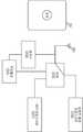
도 1은 본 발명의 일 실시예에 따른 휴대용 단말기의 일체형으로 구비된 NFC 안테나와 비접촉 충전 코일의 구분 장치의 구성을 나타낸 블럭도.
도 2는 본 발명의 일 실시예에 따른 센서부를 이용한 휴대용 단말기의 일체형으로 구비된 NFC 안테나와 비접촉 충전 코일의 구분 장치의 구성을 나타낸 블럭도.
도 3은 본 발명의 일 실시예에 따른 휴대용 단말기의 일체형으로 구비된 NFC 안테나와 비접촉 충전 코일의 구분 방법을 시간의 순서대로 나타낸 순서도.
도 4은 본 발명의 일 실시예에 따른 센서부를 이용한 휴대용 단말기의 일체형으로 구비된 NFC 안테나와 비접촉 충전 코일의 구분 방법을 시간의 순서대로 나타낸 순서도.FIG. 1 is a block diagram showing a structure of a NFC antenna and a noncontact charging coil separating apparatus, which are integrally provided in a portable terminal according to an embodiment of the present invention. FIG.
BACKGROUND OF THE INVENTION 1. Field of the Invention [0001] The present invention relates to an NFC antenna and a non-contact charging coil, and more particularly to a portable terminal using a sensor unit.
FIG. 3 is a flowchart illustrating a method of separating an NFC antenna and a non-contact charging coil integrally provided in a portable terminal according to an embodiment of the present invention in order of time.
FIG. 4 is a flowchart illustrating a method of separating an NFC antenna and a non-contact charging coil, which are integrally provided in a portable terminal using a sensor unit according to an embodiment of the present invention, in order of time.
이하, 첨부된 도면을 참조하여 본 발명이 속하는 기술분야에서 통상의 지식을 가진 자가 본 발명을 용이하게 실시할 수 있도록 바람직한 실시예를 상세히 설명한다. 다만, 본 발명의 바람직한 실시예를 상세하게 설명함에 있어, 관련된 공지 기능 또는 구성에 대한 구체적인 설명이 본 발명의 요지를 불필요하게 흐릴 수 있다고 판단되는 경우에는 그 상세한 설명을 생략한다. 또한, 유사한 기능 및 작용을 하는 부분에 대해서는 도면 전체에 걸쳐 동일한 부호를 사용한다.
Hereinafter, preferred embodiments of the present invention will be described in detail with reference to the accompanying drawings, in order that those skilled in the art can easily carry out the present invention. In the following detailed description of the preferred embodiments of the present invention, a detailed description of known functions and configurations incorporated herein will be omitted when it may make the subject matter of the present invention rather unclear. In the drawings, like reference numerals are used throughout the drawings.
도 1은 본 발명의 일 실시예에 따른 휴대용 단말기의 일체형으로 구비된 NFC 안테나와 비접촉 충전 코일의 구분 장치의 구성을 나타낸 블럭도이다. 도 1에 도시된 바와 같이, 휴대용 단말기의 일체형으로 구비된 NFC 안테나와 비접촉 충전 코일의 구분 장치는 안테나(101), 전압 검출기(102), 가변저항(103), 컨트롤러(104), 스위치(105), 비접촉 충전 트랜스시버(106) 및 NFC 트랜스시버(107)로 구비될 수 있다.FIG. 1 is a block diagram showing the construction of a separating device for an NFC antenna and a non-contact charging coil provided integrally in a portable terminal according to an embodiment of the present invention. As shown in FIG. 1, an NFC antenna and a non-contact charging coil separating apparatus, which are integrally provided in a portable terminal, include an
안테나(101)는 충전패드 또는 리더(Reader)기로부터 공급된 신호를 수신한다. 보다 구체적으로는, 비접촉 충전을 하기 위하여 휴대용 단말기를 충전패드 위에 올려놓으면, 충전 패드에서 발생 된 신호를 안테나(101)가 수신하고, 근거리 무선 통신을 하기 위하여 휴대용 단말기를 리더기에 가까이하면, 리더기에서 발생 된 신호를 안테나(101)가 수신한다.The
전압 검출기(102)는 안테나(101)와 연결되어, 안테나(101)로부터 수신된 신호를 전달받아, 안테나(101)와의 사이의 전압을 측정한다. 보다 구체적으로는, 전압 검출기(102) 내부에는 가변저항(103)이 구비되어 있어, 안테나(101)로부터 수신된 신호로 전압 검출기(102)에는 전류가 흐르게 되고, 옴의 법칙에 따라 가변저항(103)에 걸리는 단자 전압을 측정할 수 있다. 본 실시예에서는 전압 검출기(102)를 언급하였지만, 전류 검출기 또는 전력 검출기를 이용하여, 가변저항(103) 걸리는 전류 또는 전력을 측정할 수 있음은 물론이다.The
가변저항(103)은 일측에는 안테나(101)와 연결되어 있고, 타측에는 접지와 연결되어 있어, 안테나(101)와의 사이에 발생 된 전압, 전류 및 전력 값 중 어느 하나를 측정할 수 있다. 가변저항(103)의 저항값은 사용자의 설정에 의하여 임의의 저항값으로 구비될 수 있음은 물론이다.The
컨트롤러(104)는 전압 검출기(102)와 연결되어, 전압 검출기(102)에서 측정된 전압 값을 전달받아, 컨트롤러(104)와 연결된 스위치(105)를 스위칭한다. 보다 구체적으로는, 비접촉 충전 트랜스시버(106)와 NFC(Near Field Communication) 트랜스시버(107) 중 어느 하나의 방향으로 스위칭하게 된다. 즉, 전압 검출기(102)에서 측정된 전압 값이, 기 설정된 제1 값 이상으로 측정되면, 스위치(105)를 비접촉충전 트랜스시버가 위치한 방향으로 스위칭하고, 전압 검출기(102)에서 측정된 전압 값이, 기 설정된 제2 값 이하로 측정되면, 스위치(105)를 NFC 트랜스시버가 위치한 방향으로 스위칭한다.The controller 104 is connected to the
여기서, 비접촉 충전 트랜스시버(106) 방향으로 스위칭 되어, 흐르는 전류 값은 바람직하게는 약 500mA 내지 1A의 전류 값이고, NFC 트랜스시버(107)가 위치한 방향으로 스위칭 되어, 흐르는 전류 값은 바람직하게는 약 1mA 이하의 전류 값이다.Here, the value of the current flowing in the direction of the
스위치(105)는 전압 검출기(102) 및 컨트롤러(104)와 연결되어, 컨트롤러(104)의 컨트롤에 의하여 스위칭 된다.The
비접촉 충전 트랜스시버가 위치한 방향으로 스위치(105)가 스위칭 되면, 전압 검출기(102), 컨트롤러(104), 스위치(105) 및 비접촉 충전 트랜스시버(106)가 차례로 연결된다. 따라서, 단말기 커넥터에 연결해 전지를 충전하는 접촉 방식이 아닌 비접촉 방식으로 충전기에 올려놓기만 해도 충전이 자동으로 이뤄진다.When the
NFC 트랜스시버(107)가 위치한 방향으로 스위치(105)가 스위칭 되면, 전압 검출기(102), 컨트롤러(104), 스위치(105) 및 NFC 트랜스시버(107)가 차례로 연결된다. 따라서, 결제뿐만 아니라 슈퍼마켓이나 일반 상점에서 물품 정보나 방문객을 위한 여행 정보 전송, 교통, 출입통제 잠금장치 등에 사용될 수 있다.
When the
도 2는 본 발명의 일 실시예에 따른 센서부를 이용한 휴대용 단말기의 일체형으로 구비된 NFC 안테나와 비접촉 충전 코일의 구분 장치의 구성을 나타낸 블럭도이다. 도 2에 도시된 바와 같이, 센서부를 이용한 휴대용 단말기의 일체형으로 구비된 NFC 안테나와 비접촉 충전 코일의 구분 장치는 안테나(202), 센서부(203), 컨트롤러(204), 스위치(205), 비접촉 충전 트랜스시버(206) 및 NFC 트랜스시버(207)로 구비될 수 있다.FIG. 2 is a block diagram illustrating the construction of a NFC antenna and a non-contact charging coil separator in a portable terminal using a sensor unit according to an embodiment of the present invention. As shown in FIG. 2, the NFC antenna and the non-contact charging coil, which are integrally provided in the portable terminal using the sensor unit, include an
안테나(202)는 자석이 삽입된 충전패드 또는 리더기(201)로부터 공급된 자계 신호를 수신한다. 보다 구체적으로는, 비접촉 충전을 하기 위하여 휴대용 단말기를 자석이 삽입된 충전패드(201) 위에 올려놓으면, 충전패드(201)에서 발생 된 자계 신호를 센서부(203)가 수신하여 전압으로 변경해 준다.The
센서부(203)는 안테나(202)와 컨트롤러(204)와 연결되어 있다. 보다 구체적으로는, 센서부(203)는 Hall sensor 또는 MR sensor(Magnetoresistive sensor)로 구성된다. Hall sensor는 Hall Effect에 기반을 둔 센서로서, 영구자석 사이에 도체를 놓고 도체에 전기를 흘리면 기존에 있던 영구자석 사이에 발생하는 자속의 변화로 인하여 전압변화가 발생되며 그 전압변화를 측정하여 센싱을 하는 원리이다.The sensor unit 203 is connected to the
MR sensor는 자기저항 효과 소자를 이용한 센서로서, 자계의 변화나 자성체의 유무를 전압의 변화로서 검출할 수 있다. 여기서 자기저항 효과란 고체의 전기저항이 자계에 의해 변화하는 현상을 말한다. 따라서, 상술한 원리에 의하여 센서부(203)는 충전패드 또는 리더기(201)에 삽입된 자석으로부터 자계 값을 인식하여, 자계 값을 전압 값으로 변환한다.The MR sensor is a sensor using a magnetoresistance effect element, and can detect a change in magnetic field or the presence or absence of a magnetic body as a change in voltage. Here, the magnetoresistance effect refers to a phenomenon in which the electric resistance of a solid changes due to a magnetic field. Therefore, the sensor unit 203 recognizes the magnetic field value from the charging pad or the magnet inserted in the
컨트롤러(204)는 센서부(203)와 연결되어, 센서부(203)에서 변환된 전압 값을 전달받아, 컨트롤러(204)와 연결된 스위치(205)를 스위칭한다. 보다 구체적으로는, 비접촉 충전 트랜스시버(206)와 NFC 트랜스시버(207) 중 어느 하나의 방향으로 스위칭하게 된다. 즉, 센서부(203)에서 변환된 전압 값이, 기 설정된 값 이상으로 측정되면, 스위치(205)를 비접촉충전 트랜스시버가 위치한 방향으로 스위칭하고, 센서부(203)에서 측정된 전압 값이, 기 설정된 값 이하로 측정되면, 스위치(205)를 NFC 트랜스시버가 위치한 방향으로 스위칭한다.The controller 204 is connected to the sensor unit 203 and receives the voltage value converted by the sensor unit 203 and switches the switch 205 connected to the controller 204. [ More specifically, switching is performed in the direction of either of the
비접촉 충전 트랜스시버(206)와 NFC 트랜스시버(207) 중 어느 하나의 방향으로 스위칭 된 후의 각각의 기능은 도 1을 참조하여 상세히 설명한바 생략하기로 한다.
The respective functions after switching to the direction of the
도 3은 본 발명의 일 실시예에 따른 휴대용 단말기의 일체형으로 구비된 NFC 안테나와 비접촉 충전 코일의 구분 방법을 시간의 순서대로 나타낸 순서도이다. 도 3에 도시된 바와 같이, 먼저 안테나를 통하여 충전패드 또는 리더기로부터 공급된 신호를 수신한다(301). 안테나와 연결된 검출기에서는 안테나로부터 수신된 신호를 전달받아, 안테나와의 사이의 전압, 전류 또는 전력 값 중 어느 하나의 값을 검출한다(302).FIG. 3 is a flowchart illustrating a method of separating an NFC antenna and a non-contact charging coil, which are integrally provided in a portable terminal according to an embodiment of the present invention, in order of time. As shown in FIG. 3, a signal supplied from a charging pad or a reader is first received through an antenna (301). The detector connected to the antenna receives the signal received from the antenna and detects any one of voltage, current, and power between the antenna and the antenna (302).
검출기와 연결된 컨트롤러에서는 검출기에서 측정된 값을 전달받는다(303). 이후, 컨트롤러에서는 검출기로부터 전달받은 측정된 값이 기 설정된 제1 값 이상 인지 판단하는 과정을 거친다(304). 판단과정(304)에서 측정된 값이 기 설정된 제1 값 이상이라고 판단되면, 컨트롤러와 연결된 스위치를 비접촉 트랜스시버가 위치한 방향으로 스위칭하게 되고(305), 비접촉 충전과정이 진행된다.In the controller connected to the detector, the measured value is received at the detector (303). Thereafter, the controller determines whether the measured value transmitted from the detector is greater than a predetermined first value (step 304). If it is determined that the measured value is greater than the preset first value, the switch connected to the controller is switched to the direction in which the non-contact transceiver is located (305), and the non-contact charging process proceeds.
만약, 앞선 판단과정(304)에서, 측정된 값이 기 설정된 제1 값 이상이라고 판단되지 않으면(기 설정된 제2 값 이하라고 판단), 컨트롤러와 연결된 스위치를 NFC 트랜스시버가 위치한 방향으로 스위치를 스위칭하게 되고(306), 근거리 무선통신 과정이 진행된다.
If it is not determined that the measured value is equal to or greater than the preset first value (determined to be equal to or less than the predetermined second value), the switch connected to the controller is switched to the direction in which the NFC transceiver is located (306), and a short-range wireless communication process is performed.
도 4은 본 발명의 일 실시예에 따른 센서부를 이용한 휴대용 단말기의 일체형으로 구비된 NFC 안테나와 비접촉 충전 코일의 구분 방법을 시간의 순서대로 나타낸 순서도이다. 도 4에 도시된 바와 같이, 센서부는 충전패드 또는 리더기에 삽입된 자석으로부터 자계 값을 인식하여, 자계 값을 전압 값으로 변환한다(401). 센서부와 연결된 컨트롤러에서는 센서부에서 변환된 전압 값을 전달받고(402), 변환된 전압 값이 기 설정된 값 이상인지 판단하는 과정을 거친다(403).FIG. 4 is a flowchart illustrating a method of separating an NFC antenna and a non-contact charging coil provided integrally in a portable terminal using a sensor unit according to an embodiment of the present invention in order of time. As shown in FIG. 4, the sensor unit recognizes a magnetic field value from a magnet inserted in a charging pad or reader, and converts the magnetic field value into a voltage value (401). The controller connected to the sensor unit receives the converted voltage value from the sensor unit (402), and determines whether the converted voltage value is greater than a predetermined value (403).
판단과정(403)에서 변환된 전압 값이 기 설정된 전압 값 이상이라고 판단되면, 컨트롤러와 연결된 스위치를 비접촉 충전 트랜스시버가 위치한 방향으로 스위칭하게 되고(404), 비접촉 충전과정이 진행된다.If it is determined in
만약, 앞선 판단과정(403)에서 변환된 전압 값이 기 설정된 전압 값 이하라고 판단되면, 컨트롤러와 연결된 스위치를 NFC 트랜스시버가 위치한 방향으로 스위치를 스위칭하게 되고(405), 근거리 무선통신 과정이 진행된다.
If it is determined in
이상 설명한 본 발명은 본 발명이 속한 기술분야에서 통상의 지식을 가진 자에 의하여 다양한 변형이나 응용이 가능하며, 본 발명에 따른 기술적 사상의 범위는 아래의 특허청구범위에 의하여 정해져야 할 것이다.
The present invention may be embodied in many other specific forms without departing from the spirit or essential characteristics of the invention.
101: 안테나102: 전압 검출기
103: 가변저항104: 컨트롤러
105: 스위치106: 비접촉 충전 트랜스시버
107: NFC 트랜스시버201: 충전패드 또는 리더기
202: 안테나203: 센서부
204: 컨트롤러205: 스위치
206: 비접촉 충전 트랜스시버207: NFC 트랜스시버101: antenna 102: voltage detector
103: variable resistor 104: controller
105: switch 106: non-contact charging transceiver
107: NFC transceiver 201: charging pad or reader
202: antenna 203:
204: controller 205: switch
206: non-contact charging transceiver 207: NFC transceiver
Claims (12)
Translated fromKoreanNFC(near field communication) 통신을 위한 NFC 트랜스시버;
비접촉 충전을 위한 비접촉 충전 트랜스시버;
상기 안테나와 상기 NFC 트랜스시버 및 비접촉 충전트랜스시버 각각을 연결할 수 있는 스위치;
상기 충전패드 또는 상기 리더(Reader)기에 삽입된 자석으로부터 자계 값을 감지하고, 상기 자계 값을 전압 값으로 변환하는 센서부; 및
상기 변환된 전압 값에 기반하여, 상기 안테나가 상기 NFC 트랜스시버 또는 비접촉 충전 트랜스시버에 연결되도록 상기 스위치를 컨트롤하는 컨트롤러를 포함하는 것을 특징으로 하는 휴대용 단말기.
An antenna for receiving a signal supplied from a charging pad or a reader;
An NFC transceiver for near field communication (NFC) communication;
Non-contact charging transceiver for non-contact charging;
A switch for connecting the antenna, the NFC transceiver and the non-contact charging transceiver, respectively;
A sensor unit for sensing a magnetic field value from a magnet inserted in the charging pad or the reader and converting the magnetic field value into a voltage value; And
And a controller for controlling the switch so that the antenna is connected to the NFC transceiver or the non-contact charging transceiver based on the converted voltage value.
상기 안테나와 연결되어, 상기 안테나에 공급된 신호의 전압, 전류 또는 전력 값 중 어느 하나를 측정하는 검출기(Detector)를 더 포함하고,
상기 컨트롤러는,
상기 검출기에서 측정된 전압, 전류 또는 전력 값 중 어느 하나의 값이, 기 설정된 제1 값 이상으로 측정되면, 상기 스위치를 상기 비접촉 충전 트랜스시버가 위치한 방향으로 스위칭하고,
상기 검출기에서 측정된 전압, 전류 또는 전력 값 중 어느 하나의 값이, 기 설정된 제2 값 이하로 측정되면, 상기 스위치를 상기 NFC 트랜스시버가 위치한 방향으로 스위칭하는 것을 특징으로 하는 휴대용 단말기.
The method according to claim 1,
And a detector connected to the antenna and measuring one of a voltage, a current, and a power of a signal supplied to the antenna,
The controller comprising:
Switching the switch to the direction in which the non-contact charging transceiver is located if any one of the voltage, current, or power value measured by the detector is greater than a predetermined first value,
And switches the switch in a direction in which the NFC transceiver is located if any one of a voltage, a current, and a power value measured by the detector is less than or equal to a predetermined second value.
상기 기 설정된 제1 전류 값은, 500mA 내지 1A의 전류 값이고,
상기 기 설정된 제2 전류 값은, 1mA 이하의 전류 값인 것을 특징으로 하는 휴대용 단말기.
3. The method of claim 2,
The predetermined first current value is a current value of 500 mA to 1 A,
Wherein the predetermined second current value is a current value of 1 mA or less.
일측에는 상기 안테나와 연결되어 있고, 타측에는 접지와 연결되어 있어, 상기 안테나와의 사이에 발생 된 전압, 전류 및 전력 값 중 어느 하나를 측정할 수 있는 가변저항을 포함하는 것을 특징으로 하는 휴대용 단말기.
3. The apparatus of claim 2,
And a variable resistor connected to the antenna at one side and to ground at the other side for measuring any one of a voltage, a current and a power value generated between the antenna and the antenna. .
상기 변환된 전압 값이, 기 설정된 값 이상으로 측정되면, 상기 스위치를 상기 비접촉 충전 트랜스시버가 위치한 방향으로 스위칭하고,
상기 센서부로부터 전달받은 상기 전압 값이, 기 설정된 값 이하로 측정되면, 상기 스위치를 상기 NFC 트랜스시버가 위치한 방향으로 스위칭하는 것을 특징으로 하는 휴대용 단말기.
2. The apparatus of claim 1,
Switching the switch to the direction in which the non-contact charging transceiver is located if the converted voltage value is measured to be greater than a predetermined value,
Wherein the switching unit switches the switch in a direction in which the NFC transceiver is located when the voltage value received from the sensor unit is measured to be less than a predetermined value.
센서부가 상기 충전패드 또는 상기 리더(Reader)기에 삽입된 자석으로부터 자계 값을 인식하고 상기 자계 값을 전압 값으로 변환하는 과정;
컨트롤러가 상기 센서부로부터 상기 전압 값을 전달받는 과정;
상기 컨트롤러가 상기 변환된 전압값에 기반하여, 상기 안테나가, NFC(Near Field Communication) 통신을 위한 NFC 트랜스시버에 연결되도록 스위칭하거나, 비접촉 충전을 위한 비접촉 충전 트랜스시버에 연결되도록 스위칭하는 스위치를 컨트롤하는 과정을 포함하는 것을 특징으로 하는 휴대용 단말기의 동작 방법.
A process in which an antenna receives a signal supplied from a charging pad or a reader;
Recognizing a magnetic field value from a magnet inserted into the charging pad or the reader and converting the magnetic field value into a voltage value;
The controller receiving the voltage value from the sensor unit;
The controller controls the switch to switch the antenna to be connected to the NFC transceiver for NFC (Near Field Communication) communication or to switch the antenna to be connected to the noncontact charging transceiver for non-contact charging based on the converted voltage value The method comprising the steps of:
상기 컨트롤러가,
상기 검출기에서 측정된 전압, 전류 또는 전력 값 중 어느 하나의 값이, 기 설정된 제1 값 이상으로 측정되면, 상기 스위치를 상기 비접촉 충전 트랜스시버가 위치한 방향으로 스위칭하고,
상기 검출기에서 측정된 전압, 전류 또는 전력 값 중 어느 하나의 값이, 기 설정된 제2 값 이하로 측정되면, 상기 스위치를 상기 NFC 트랜스시버가 위치한 방향으로 스위칭하는 과정을 더 포함하는 것을 특징으로 하는 휴대용 단말기의 동작 방법.
8. The method of claim 7, further comprising the step of the detector measuring the voltage, current, or power value of the signal received by the antenna,
Wherein,
Switching the switch to the direction in which the non-contact charging transceiver is located if any one of the voltage, current, or power value measured by the detector is greater than a predetermined first value,
And switching the switch in a direction in which the NFC transceiver is located if any one of the voltage, current, or power value measured by the detector is less than or equal to a predetermined second value A method of operating a terminal.
상기 기 설정된 제1 전류 값은, 500mA 내지 1A의 전류 값이고,
상기 기 설정된 제2 전류 값은, 1mA 이하의 전류 값인 것을 특징으로 하는 휴대용 단말기의 동작 방법.
9. The method of claim 8,
The predetermined first current value is a current value of 500 mA to 1 A,
Wherein the predetermined second current value is a current value of 1 mA or less.
일측에는 상기 안테나와 연결되어 있고, 타측에는 접지와 연결되어 있어, 상기 안테나와의 사이에 발생 된 전압, 전류 및 전력 값 중 어느 하나를 측정할 수 있는 가변저항을 포함하는 것을 특징으로 하는 휴대용 단말기의 동작 방법.
9. The apparatus of claim 8,
And a variable resistor connected to the antenna at one side and to ground at the other side for measuring any one of a voltage, a current and a power value generated between the antenna and the antenna. Lt; / RTI >
상기 센서부로부터 전달받은 상기 전압 값이, 기 설정된 값 이상으로 측정되면, 상기 스위치를 상기 비접촉 충전 트랜스시버가 위치한 방향으로 스위칭하고,
상기 센서부로부터 전달받은 상기 전압 값이, 기 설정된 값 이하로 측정되면, 상기 스위치를 상기 NFC 트랜스시버가 위치한 방향으로 스위칭하는 것을 특징으로 하는 휴대용 단말기의 동작 방법.
8. The apparatus of claim 7,
When the voltage value received from the sensor unit is measured to be equal to or greater than a predetermined value, the switch is switched to the direction in which the non-contact charging transceiver is located,
And switches the switch in a direction in which the NFC transceiver is located if the voltage value received from the sensor unit is measured to be less than a predetermined value.
Priority Applications (3)
| Application Number | Priority Date | Filing Date | Title |
|---|---|---|---|
| KR1020110082050AKR101830960B1 (en) | 2011-08-18 | 2011-08-18 | Detecting apparatas and method for having integrated a nfc antenna and non-contact charging coil in a user terminal |
| US13/588,471US8957633B2 (en) | 2011-08-18 | 2012-08-17 | Apparatus and method for non-contact recharging and near field communication in a portable electronic device |
| US14/615,781US9300164B2 (en) | 2011-08-18 | 2015-02-06 | Apparatus and method for non-contact recharging and near field communication in a portable electronic device |
Applications Claiming Priority (1)
| Application Number | Priority Date | Filing Date | Title |
|---|---|---|---|
| KR1020110082050AKR101830960B1 (en) | 2011-08-18 | 2011-08-18 | Detecting apparatas and method for having integrated a nfc antenna and non-contact charging coil in a user terminal |
Publications (2)
| Publication Number | Publication Date |
|---|---|
| KR20130019830A KR20130019830A (en) | 2013-02-27 |
| KR101830960B1true KR101830960B1 (en) | 2018-02-22 |
Family
ID=47712190
Family Applications (1)
| Application Number | Title | Priority Date | Filing Date |
|---|---|---|---|
| KR1020110082050AExpired - Fee RelatedKR101830960B1 (en) | 2011-08-18 | 2011-08-18 | Detecting apparatas and method for having integrated a nfc antenna and non-contact charging coil in a user terminal |
Country Status (2)
| Country | Link |
|---|---|
| US (2) | US8957633B2 (en) |
| KR (1) | KR101830960B1 (en) |
Families Citing this family (31)
| Publication number | Priority date | Publication date | Assignee | Title |
|---|---|---|---|---|
| US8548380B2 (en)* | 2011-06-10 | 2013-10-01 | Broadcom Corporation | Communications device for intelligently routing information among multiple user interfaces |
| KR101830960B1 (en)* | 2011-08-18 | 2018-02-22 | 삼성전자주식회사 | Detecting apparatas and method for having integrated a nfc antenna and non-contact charging coil in a user terminal |
| US8824597B2 (en)* | 2012-09-07 | 2014-09-02 | Texas Instruments Incorporated | Circuits and methods for field-based communication |
| US9496744B2 (en)* | 2012-12-20 | 2016-11-15 | Intel Corporation | Wireless charging optimization utilizing an NFC module that detects induced current and provides an indication of induced current |
| US9270343B2 (en)* | 2012-12-20 | 2016-02-23 | Nxp B.V. | Wireless charging recognizing receiver movement over charging pad with NFC antenna array |
| KR102052443B1 (en)* | 2013-02-13 | 2019-12-05 | 삼성전자주식회사 | System for performing charging and data communication |
| US9559544B2 (en) | 2013-03-15 | 2017-01-31 | Jay Marketing Associates, Inc. | Wireless interrogation and wireless charging of electronic devices |
| CN103347147B (en) | 2013-06-09 | 2016-08-03 | 小米科技有限责任公司 | Multiturn coil multiplex circuit, the control method of multiturn coil multiplex circuit and equipment |
| CN103413379B (en)* | 2013-07-31 | 2015-12-09 | 小米科技有限责任公司 | A kind of recharge method, terminal and rechargeable card |
| CN103413165B (en)* | 2013-08-07 | 2017-08-25 | 歌尔股份有限公司 | Control the method and controlled NFC label of NFC label |
| US20150091523A1 (en)* | 2013-10-02 | 2015-04-02 | Mediatek Singapore Pte. Ltd. | Wireless charger system that has variable power / adaptive load modulation |
| JP2015076737A (en)* | 2013-10-09 | 2015-04-20 | 株式会社東芝 | Wireless communication apparatus, wireless communication system, wireless communication method, and wireless device |
| JP6218545B2 (en)* | 2013-10-09 | 2017-10-25 | キヤノン株式会社 | Power supply apparatus, control method, and program |
| KR102048016B1 (en)* | 2013-12-30 | 2019-11-22 | 삼성전자주식회사 | NFC Terminal and Comunication Device including Thereof |
| JP6381305B2 (en)* | 2014-06-10 | 2018-08-29 | キヤノン株式会社 | Electronics |
| JP6381304B2 (en)* | 2014-06-10 | 2018-08-29 | キヤノン株式会社 | Electronics |
| CN105245019B (en)* | 2014-07-07 | 2017-09-29 | 宏达国际电子股份有限公司 | Near field communication and wireless charging device and switching method thereof |
| KR102242363B1 (en)* | 2014-09-11 | 2021-04-20 | 삼성전자주식회사 | Electronic apparatus and method for grip sensing |
| US10355535B2 (en)* | 2016-04-01 | 2019-07-16 | Electrolux Home Products, Inc. | Appliance for wireless power and data transfer |
| KR101846953B1 (en)* | 2016-04-06 | 2018-04-09 | 주식회사 맵스 | Communication apparatus and electronic device having the protection function from wireless recharging |
| WO2017217686A1 (en)* | 2016-06-16 | 2017-12-21 | Samsung Electronics Co., Ltd. | Wireless power transmitter, wireless power receiver, and control methods thereof |
| CN107147220A (en)* | 2017-04-19 | 2017-09-08 | 苏州横空电子科技有限公司 | The method that the resonance type wireless charging system and its NFC of NFC label are read can be read |
| FR3066656A1 (en)* | 2017-05-19 | 2018-11-23 | Continental Automotive France | NEAR FIELD APPROACH DETECTION AND COMMUNICATION DETECTION DEVICE |
| CN107181819B (en)* | 2017-06-29 | 2025-02-07 | 深圳来电科技有限公司 | A system for sharing charging device and a charging method for sharing charging device |
| US10356537B2 (en) | 2017-12-01 | 2019-07-16 | Semiconductor Components Industries, Llc | All-in-one method for wireless connectivity and contactless battery charging of small wearables |
| CN109995927B (en)* | 2017-12-29 | 2021-02-09 | Oppo广东移动通信有限公司 | Information processing method and device, mobile terminal and computer readable storage medium |
| CN110380517B (en)* | 2018-04-11 | 2022-10-21 | 台达电子工业股份有限公司 | Wireless power transmission system and transmission method |
| EP3681005A1 (en)* | 2019-01-08 | 2020-07-15 | Energysquare | Reporting device for multimodal article interface |
| EP4074073A1 (en)* | 2019-12-12 | 2022-10-19 | Widex A/S | Hearing assistive device having a rechargeable battery |
| CN111817393B (en)* | 2020-07-17 | 2022-06-28 | 上海布鲁可积木科技有限公司 | Charging and communication switching circuit capable of charging networking structure between paired pieces |
| WO2022086529A1 (en)* | 2020-10-22 | 2022-04-28 | Hewlett-Packard Development Company, L.P. | Magnetic flux-controlled antenna |
Citations (2)
| Publication number | Priority date | Publication date | Assignee | Title |
|---|---|---|---|---|
| WO2010035256A2 (en)* | 2008-09-23 | 2010-04-01 | Powermat Ltd. | Combined antenna and inductive power receiver |
| US20100279606A1 (en)* | 2009-02-13 | 2010-11-04 | Qualcomm Incorporated | Wireless power and wireless communication for electronic devices |
Family Cites Families (32)
| Publication number | Priority date | Publication date | Assignee | Title |
|---|---|---|---|---|
| DE10012637B4 (en)* | 2000-03-15 | 2005-09-01 | Texas Instruments Deutschland Gmbh | Security system to enable the authenticated access of an individual to a protected area |
| JP2004023765A (en)* | 2002-06-20 | 2004-01-22 | Sanyo Electric Co Ltd | Radio data transmission apparatus |
| CA2533029C (en)* | 2003-07-22 | 2014-06-03 | Nokia Corporation | Reader device for radio frequency identification transponder with transponder functionality |
| US9020430B2 (en)* | 2004-10-12 | 2015-04-28 | Nokia Corporation | Methods, apparatus, systems and computer program products for energy management of short-range communication modules in mobile terminal devices |
| US20060145660A1 (en)* | 2004-12-30 | 2006-07-06 | Black Greg R | Method and apparatus for near field communications |
| GB0501115D0 (en)* | 2005-01-19 | 2005-02-23 | Innovision Res & Tech Plc | Combined power coupling and rf communication apparatus |
| JP4528332B2 (en)* | 2005-02-09 | 2010-08-18 | エヌエックスピー ビー ヴィ | Method for ensuring safe NFC function of wireless mobile communication device, and wireless mobile communication device having safe NFC function |
| GB0507285D0 (en)* | 2005-04-11 | 2005-05-18 | Innovision Res & Tech Plc | Nfc enabled high-speed data |
| US8244179B2 (en)* | 2005-05-12 | 2012-08-14 | Robin Dua | Wireless inter-device data processing configured through inter-device transmitted data |
| US8169185B2 (en)* | 2006-01-31 | 2012-05-01 | Mojo Mobility, Inc. | System and method for inductive charging of portable devices |
| US7952322B2 (en)* | 2006-01-31 | 2011-05-31 | Mojo Mobility, Inc. | Inductive power source and charging system |
| US7948208B2 (en)* | 2006-06-01 | 2011-05-24 | Mojo Mobility, Inc. | Power source, charging system, and inductive receiver for mobile devices |
| US20090001930A1 (en)* | 2007-06-29 | 2009-01-01 | Nokia Corporation | Electronic apparatus and associated methods |
| US8212518B2 (en)* | 2007-10-15 | 2012-07-03 | Nxp B.V. | Method of controlling a power transfer system and power transfer system |
| US8228025B2 (en)* | 2007-11-09 | 2012-07-24 | City University Of Hong Kong | Electronic control method for a planar inductive battery charging apparatus |
| US7912441B2 (en)* | 2007-12-11 | 2011-03-22 | Motorola Mobility, Inc. | Apparatus and method for enabling near field communication equipment in a portable communications device |
| US8674808B2 (en)* | 2008-02-29 | 2014-03-18 | Nokia Corporation | Interrogation of RFID communication units |
| US8855554B2 (en)* | 2008-03-05 | 2014-10-07 | Qualcomm Incorporated | Packaging and details of a wireless power device |
| US9337902B2 (en)* | 2008-03-17 | 2016-05-10 | Powermat Technologies Ltd. | System and method for providing wireless power transfer functionality to an electrical device |
| WO2010020895A2 (en)* | 2008-08-18 | 2010-02-25 | Nxp B.V. | A mobile device to control a charge pad system |
| US20140349572A1 (en)* | 2008-09-23 | 2014-11-27 | Powermat Technologies Ltd. | Integrated inductive power receiver and near field communicator |
| US8497658B2 (en)* | 2009-01-22 | 2013-07-30 | Qualcomm Incorporated | Adaptive power control for wireless charging of devices |
| KR100911032B1 (en)* | 2009-04-01 | 2009-08-05 | (주)애니쿼터스 | Apparatus and method for controlling the ringtone, camera, and communication functions of a mobile phone terminal through an NFC chip module and an external RF reader |
| US8188851B2 (en)* | 2009-05-04 | 2012-05-29 | Sony Mobile Communications Ab | Wake-up system and method for an electronic apparatus |
| US8390249B2 (en)* | 2009-11-30 | 2013-03-05 | Broadcom Corporation | Battery with integrated wireless power receiver and/or RFID |
| KR100980052B1 (en) | 2010-04-29 | 2010-09-06 | (주) 아이씨티케이 | Power supply and communication branching interface system of mobile device using near field communication |
| JP5755066B2 (en)* | 2010-07-30 | 2015-07-29 | 株式会社半導体エネルギー研究所 | Wireless power feeding system and wireless power feeding method |
| WO2012019011A1 (en)* | 2010-08-04 | 2012-02-09 | Johnson Controls Technology Company | Universal wireless charging system for motor vehicles |
| WO2012016336A2 (en)* | 2010-08-06 | 2012-02-09 | Cynetic Designs Ltd. | Inductive transmission of power and data through ceramic armor panels |
| US8983374B2 (en)* | 2010-12-13 | 2015-03-17 | Qualcomm Incorporated | Receiver for near field communication and wireless power functionalities |
| US9178369B2 (en)* | 2011-01-18 | 2015-11-03 | Mojo Mobility, Inc. | Systems and methods for providing positioning freedom, and support of different voltages, protocols, and power levels in a wireless power system |
| KR101830960B1 (en)* | 2011-08-18 | 2018-02-22 | 삼성전자주식회사 | Detecting apparatas and method for having integrated a nfc antenna and non-contact charging coil in a user terminal |
- 2011
- 2011-08-18KRKR1020110082050Apatent/KR101830960B1/ennot_activeExpired - Fee Related
- 2012
- 2012-08-17USUS13/588,471patent/US8957633B2/ennot_activeExpired - Fee Related
- 2015
- 2015-02-06USUS14/615,781patent/US9300164B2/ennot_activeExpired - Fee Related
Patent Citations (2)
| Publication number | Priority date | Publication date | Assignee | Title |
|---|---|---|---|---|
| WO2010035256A2 (en)* | 2008-09-23 | 2010-04-01 | Powermat Ltd. | Combined antenna and inductive power receiver |
| US20100279606A1 (en)* | 2009-02-13 | 2010-11-04 | Qualcomm Incorporated | Wireless power and wireless communication for electronic devices |
Also Published As
| Publication number | Publication date |
|---|---|
| US20130043835A1 (en) | 2013-02-21 |
| KR20130019830A (en) | 2013-02-27 |
| US9300164B2 (en) | 2016-03-29 |
| US8957633B2 (en) | 2015-02-17 |
| US20150155740A1 (en) | 2015-06-04 |
Similar Documents
| Publication | Publication Date | Title |
|---|---|---|
| KR101830960B1 (en) | Detecting apparatas and method for having integrated a nfc antenna and non-contact charging coil in a user terminal | |
| KR102224451B1 (en) | Power receiver and power transmitter | |
| JP6466557B2 (en) | Detection device and power transmission device | |
| KR101983612B1 (en) | Smart phone with the reciever for the wireless charging | |
| CN202334469U (en) | Selection circuit of near field communication and wireless charging shared induction module | |
| CN110266119B (en) | Detection apparatus, power supply system, and method of controlling detection apparatus | |
| KR101250266B1 (en) | Wireless charger to charge battery of mobile comunication device having different capacity and method thereof | |
| CN102265480A (en) | Combined Antenna and Inductive Power Receiver | |
| JP5924050B2 (en) | Power feeding device, power receiving device, power feeding method, power receiving method, and program | |
| US20130154386A1 (en) | Wireless power transmitter, wireless power receiver and wireless power transmission method | |
| KR101214534B1 (en) | Device for Sharing and Selecting terminal of Wireless Power and Near Field Communication in Mobile | |
| KR20190047727A (en) | METHODS AND APPARATUS FOR POSITIONING A VEHICLE USING EXTERNAL OBJECT DETECTION | |
| AU2016382628B2 (en) | Wireless power transfer device and method | |
| CN103887841A (en) | Apparatus and method for wirelessly charging | |
| KR101185681B1 (en) | Antenna for both wireless power and near field communication in mobile | |
| CN103886359A (en) | Mobile phone card with radio frequency identification function | |
| CN104935088A (en) | Method of using non-contact card reader to charge | |
| KR101136917B1 (en) | Wireless charger and charging method | |
| TWM424551U (en) | Selection circuit of induction module commonly-used for near-field communication and wireless charging | |
| CN102708400B (en) | A kind of RFID label tag, rfid system and magnetic field detection method with magnetically sensitive device | |
| KR102540921B1 (en) | Wireless charger for a vehicle and operating method thereof | |
| KR102810126B1 (en) | Method for wirelessly providing power and electronic device supporting the same | |
| KR20120008890A (en) | Wireless charging device and method | |
| KR20160121072A (en) | The wireless antenna coil for the smart phone | |
| KR20150050745A (en) | Apparatus and method for charging power in wireless charging device |
Legal Events
| Date | Code | Title | Description |
|---|---|---|---|
| PA0109 | Patent application | St.27 status event code:A-0-1-A10-A12-nap-PA0109 | |
| R18-X000 | Changes to party contact information recorded | St.27 status event code:A-3-3-R10-R18-oth-X000 | |
| PG1501 | Laying open of application | St.27 status event code:A-1-1-Q10-Q12-nap-PG1501 | |
| A201 | Request for examination | ||
| PA0201 | Request for examination | St.27 status event code:A-1-2-D10-D11-exm-PA0201 | |
| E902 | Notification of reason for refusal | ||
| PE0902 | Notice of grounds for rejection | St.27 status event code:A-1-2-D10-D21-exm-PE0902 | |
| E13-X000 | Pre-grant limitation requested | St.27 status event code:A-2-3-E10-E13-lim-X000 | |
| P11-X000 | Amendment of application requested | St.27 status event code:A-2-2-P10-P11-nap-X000 | |
| P13-X000 | Application amended | St.27 status event code:A-2-2-P10-P13-nap-X000 | |
| E701 | Decision to grant or registration of patent right | ||
| PE0701 | Decision of registration | St.27 status event code:A-1-2-D10-D22-exm-PE0701 | |
| PR0701 | Registration of establishment | St.27 status event code:A-2-4-F10-F11-exm-PR0701 | |
| PR1002 | Payment of registration fee | St.27 status event code:A-2-2-U10-U11-oth-PR1002 Fee payment year number:1 | |
| PG1601 | Publication of registration | St.27 status event code:A-4-4-Q10-Q13-nap-PG1601 | |
| P22-X000 | Classification modified | St.27 status event code:A-4-4-P10-P22-nap-X000 | |
| P22-X000 | Classification modified | St.27 status event code:A-4-4-P10-P22-nap-X000 | |
| PR1001 | Payment of annual fee | St.27 status event code:A-4-4-U10-U11-oth-PR1001 Fee payment year number:4 | |
| P22-X000 | Classification modified | St.27 status event code:A-4-4-P10-P22-nap-X000 | |
| PC1903 | Unpaid annual fee | St.27 status event code:A-4-4-U10-U13-oth-PC1903 Not in force date:20220214 Payment event data comment text:Termination Category : DEFAULT_OF_REGISTRATION_FEE | |
| PC1903 | Unpaid annual fee | St.27 status event code:N-4-6-H10-H13-oth-PC1903 Ip right cessation event data comment text:Termination Category : DEFAULT_OF_REGISTRATION_FEE Not in force date:20220214 | |
| P22-X000 | Classification modified | St.27 status event code:A-4-4-P10-P22-nap-X000 |