KR101826760B1 - Handle structure of a cooker having a glass cooking vessel - Google Patents
Handle structure of a cooker having a glass cooking vesselDownload PDFInfo
- Publication number
- KR101826760B1 KR101826760B1KR1020170091273AKR20170091273AKR101826760B1KR 101826760 B1KR101826760 B1KR 101826760B1KR 1020170091273 AKR1020170091273 AKR 1020170091273AKR 20170091273 AKR20170091273 AKR 20170091273AKR 101826760 B1KR101826760 B1KR 101826760B1
- Authority
- KR
- South Korea
- Prior art keywords
- handle
- coupling protrusion
- base
- glass
- reinforcing ribs
- Prior art date
- Legal status (The legal status is an assumption and is not a legal conclusion. Google has not performed a legal analysis and makes no representation as to the accuracy of the status listed.)
- Active
Links
- 238000010411cookingMethods0.000titleclaimsabstractdescription128
- 239000011521glassSubstances0.000titleclaimsabstractdescription84
- 230000008878couplingEffects0.000claimsabstractdescription50
- 238000010168coupling processMethods0.000claimsabstractdescription50
- 238000005859coupling reactionMethods0.000claimsabstractdescription50
- 230000003014reinforcing effectEffects0.000claimsdescription32
- 238000000034methodMethods0.000claimsdescription9
- 238000009434installationMethods0.000claimsdescription6
- 230000002093peripheral effectEffects0.000claimsdescription5
- 235000013305foodNutrition0.000abstractdescription13
- 238000010438heat treatmentMethods0.000abstractdescription8
- 238000013016dampingMethods0.000abstractdescription2
- 239000000463materialSubstances0.000description10
- 235000011389fruit/vegetable juiceNutrition0.000description4
- 238000001514detection methodMethods0.000description3
- 235000013527bean curdNutrition0.000description2
- 238000005452bendingMethods0.000description2
- 235000014347soupsNutrition0.000description2
- YVGGHNCTFXOJCH-UHFFFAOYSA-NDDTChemical compoundC1=CC(Cl)=CC=C1C(C(Cl)(Cl)Cl)C1=CC=C(Cl)C=C1YVGGHNCTFXOJCH-UHFFFAOYSA-N0.000description1
- 235000010469Glycine maxNutrition0.000description1
- 244000068988Glycine maxSpecies0.000description1
- 230000002238attenuated effectEffects0.000description1
- 230000002146bilateral effectEffects0.000description1
- 230000005540biological transmissionEffects0.000description1
- 230000002860competitive effectEffects0.000description1
- 150000001875compoundsChemical class0.000description1
- 235000013399edible fruitsNutrition0.000description1
- 238000005516engineering processMethods0.000description1
- 239000006260foamSubstances0.000description1
- 235000012041food componentNutrition0.000description1
- 239000005417food ingredientSubstances0.000description1
- 239000002184metalSubstances0.000description1
- 239000007769metal materialSubstances0.000description1
- 235000013336milkNutrition0.000description1
- 239000008267milkSubstances0.000description1
- 210000004080milkAnatomy0.000description1
- 239000000203mixtureSubstances0.000description1
- 235000021395porridgeNutrition0.000description1
- 238000003672processing methodMethods0.000description1
- 235000013322soy milkNutrition0.000description1
- 229910001220stainless steelInorganic materials0.000description1
- 239000010935stainless steelSubstances0.000description1
- 235000015192vegetable juiceNutrition0.000description1
- 235000013311vegetablesNutrition0.000description1
- 230000000007visual effectEffects0.000description1
Images


Classifications
- A—HUMAN NECESSITIES
- A47—FURNITURE; DOMESTIC ARTICLES OR APPLIANCES; COFFEE MILLS; SPICE MILLS; SUCTION CLEANERS IN GENERAL
- A47J—KITCHEN EQUIPMENT; COFFEE MILLS; SPICE MILLS; APPARATUS FOR MAKING BEVERAGES
- A47J27/00—Cooking-vessels
- A47J27/004—Cooking-vessels with integral electrical heating means
- A—HUMAN NECESSITIES
- A47—FURNITURE; DOMESTIC ARTICLES OR APPLIANCES; COFFEE MILLS; SPICE MILLS; SUCTION CLEANERS IN GENERAL
- A47J—KITCHEN EQUIPMENT; COFFEE MILLS; SPICE MILLS; APPARATUS FOR MAKING BEVERAGES
- A47J45/00—Devices for fastening or gripping kitchen utensils or crockery
- A47J45/06—Handles for hollow-ware articles
- A—HUMAN NECESSITIES
- A47—FURNITURE; DOMESTIC ARTICLES OR APPLIANCES; COFFEE MILLS; SPICE MILLS; SUCTION CLEANERS IN GENERAL
- A47J—KITCHEN EQUIPMENT; COFFEE MILLS; SPICE MILLS; APPARATUS FOR MAKING BEVERAGES
- A47J36/00—Parts, details or accessories of cooking-vessels
- A47J36/24—Warming devices
- A—HUMAN NECESSITIES
- A47—FURNITURE; DOMESTIC ARTICLES OR APPLIANCES; COFFEE MILLS; SPICE MILLS; SUCTION CLEANERS IN GENERAL
- A47J—KITCHEN EQUIPMENT; COFFEE MILLS; SPICE MILLS; APPARATUS FOR MAKING BEVERAGES
- A47J36/00—Parts, details or accessories of cooking-vessels
- A47J36/16—Inserts
- A47J36/165—Stirring devices operatively connected to cooking vessels when being removably inserted inside
- A—HUMAN NECESSITIES
- A47—FURNITURE; DOMESTIC ARTICLES OR APPLIANCES; COFFEE MILLS; SPICE MILLS; SUCTION CLEANERS IN GENERAL
- A47J—KITCHEN EQUIPMENT; COFFEE MILLS; SPICE MILLS; APPARATUS FOR MAKING BEVERAGES
- A47J43/00—Implements for preparing or holding food, not provided for in other groups of this subclass
- A47J43/04—Machines for domestic use not covered elsewhere, e.g. for grinding, mixing, stirring, kneading, emulsifying, whipping or beating foodstuffs, e.g. power-driven
- A47J43/046—Machines for domestic use not covered elsewhere, e.g. for grinding, mixing, stirring, kneading, emulsifying, whipping or beating foodstuffs, e.g. power-driven with tools driven from the bottom side
- A—HUMAN NECESSITIES
- A47—FURNITURE; DOMESTIC ARTICLES OR APPLIANCES; COFFEE MILLS; SPICE MILLS; SUCTION CLEANERS IN GENERAL
- A47J—KITCHEN EQUIPMENT; COFFEE MILLS; SPICE MILLS; APPARATUS FOR MAKING BEVERAGES
- A47J43/00—Implements for preparing or holding food, not provided for in other groups of this subclass
- A47J43/04—Machines for domestic use not covered elsewhere, e.g. for grinding, mixing, stirring, kneading, emulsifying, whipping or beating foodstuffs, e.g. power-driven
- A47J43/07—Parts or details, e.g. mixing tools, whipping tools
- A47J43/0727—Mixing bowls
- A—HUMAN NECESSITIES
- A47—FURNITURE; DOMESTIC ARTICLES OR APPLIANCES; COFFEE MILLS; SPICE MILLS; SUCTION CLEANERS IN GENERAL
- A47J—KITCHEN EQUIPMENT; COFFEE MILLS; SPICE MILLS; APPARATUS FOR MAKING BEVERAGES
- A47J43/00—Implements for preparing or holding food, not provided for in other groups of this subclass
- A47J43/04—Machines for domestic use not covered elsewhere, e.g. for grinding, mixing, stirring, kneading, emulsifying, whipping or beating foodstuffs, e.g. power-driven
- A47J43/07—Parts or details, e.g. mixing tools, whipping tools
- A47J43/075—Safety devices
- A47J43/0761—Safety devices for machines with tools driven from the lower side
- A47J43/0766—Safety devices for machines with tools driven from the lower side activated by the proper positioning of the mixing bowl
- A—HUMAN NECESSITIES
- A47—FURNITURE; DOMESTIC ARTICLES OR APPLIANCES; COFFEE MILLS; SPICE MILLS; SUCTION CLEANERS IN GENERAL
- A47J—KITCHEN EQUIPMENT; COFFEE MILLS; SPICE MILLS; APPARATUS FOR MAKING BEVERAGES
- A47J43/00—Implements for preparing or holding food, not provided for in other groups of this subclass
- A47J43/04—Machines for domestic use not covered elsewhere, e.g. for grinding, mixing, stirring, kneading, emulsifying, whipping or beating foodstuffs, e.g. power-driven
- A47J43/07—Parts or details, e.g. mixing tools, whipping tools
- A47J43/075—Safety devices
- A47J43/0761—Safety devices for machines with tools driven from the lower side
- A47J43/0772—Safety devices for machines with tools driven from the lower side activated by the proper positioning of the cover
- A—HUMAN NECESSITIES
- A47—FURNITURE; DOMESTIC ARTICLES OR APPLIANCES; COFFEE MILLS; SPICE MILLS; SUCTION CLEANERS IN GENERAL
- A47J—KITCHEN EQUIPMENT; COFFEE MILLS; SPICE MILLS; APPARATUS FOR MAKING BEVERAGES
- A47J43/00—Implements for preparing or holding food, not provided for in other groups of this subclass
- A47J43/04—Machines for domestic use not covered elsewhere, e.g. for grinding, mixing, stirring, kneading, emulsifying, whipping or beating foodstuffs, e.g. power-driven
- A47J43/07—Parts or details, e.g. mixing tools, whipping tools
- A47J43/08—Driving mechanisms
- A—HUMAN NECESSITIES
- A47—FURNITURE; DOMESTIC ARTICLES OR APPLIANCES; COFFEE MILLS; SPICE MILLS; SUCTION CLEANERS IN GENERAL
- A47J—KITCHEN EQUIPMENT; COFFEE MILLS; SPICE MILLS; APPARATUS FOR MAKING BEVERAGES
- A47J45/00—Devices for fastening or gripping kitchen utensils or crockery
- A47J45/06—Handles for hollow-ware articles
- A47J45/07—Handles for hollow-ware articles of detachable type
- A47J45/077—Collar handles
- A—HUMAN NECESSITIES
- A47—FURNITURE; DOMESTIC ARTICLES OR APPLIANCES; COFFEE MILLS; SPICE MILLS; SUCTION CLEANERS IN GENERAL
- A47J—KITCHEN EQUIPMENT; COFFEE MILLS; SPICE MILLS; APPARATUS FOR MAKING BEVERAGES
- A47J45/00—Devices for fastening or gripping kitchen utensils or crockery
- A47J45/06—Handles for hollow-ware articles
- A47J45/08—Heat-insulating handles
- A—HUMAN NECESSITIES
- A47—FURNITURE; DOMESTIC ARTICLES OR APPLIANCES; COFFEE MILLS; SPICE MILLS; SUCTION CLEANERS IN GENERAL
- A47J—KITCHEN EQUIPMENT; COFFEE MILLS; SPICE MILLS; APPARATUS FOR MAKING BEVERAGES
- A47J2202/00—Devices having temperature indicating means
- A—HUMAN NECESSITIES
- A47—FURNITURE; DOMESTIC ARTICLES OR APPLIANCES; COFFEE MILLS; SPICE MILLS; SUCTION CLEANERS IN GENERAL
- A47J—KITCHEN EQUIPMENT; COFFEE MILLS; SPICE MILLS; APPARATUS FOR MAKING BEVERAGES
- A47J2203/00—Devices having filling level indicating means
- A—HUMAN NECESSITIES
- A47—FURNITURE; DOMESTIC ARTICLES OR APPLIANCES; COFFEE MILLS; SPICE MILLS; SUCTION CLEANERS IN GENERAL
- A47J—KITCHEN EQUIPMENT; COFFEE MILLS; SPICE MILLS; APPARATUS FOR MAKING BEVERAGES
- A47J43/00—Implements for preparing or holding food, not provided for in other groups of this subclass
- A47J43/04—Machines for domestic use not covered elsewhere, e.g. for grinding, mixing, stirring, kneading, emulsifying, whipping or beating foodstuffs, e.g. power-driven
- A47J43/07—Parts or details, e.g. mixing tools, whipping tools
- A47J43/0716—Parts or details, e.g. mixing tools, whipping tools for machines with tools driven from the lower side
- A—HUMAN NECESSITIES
- A47—FURNITURE; DOMESTIC ARTICLES OR APPLIANCES; COFFEE MILLS; SPICE MILLS; SUCTION CLEANERS IN GENERAL
- A47J—KITCHEN EQUIPMENT; COFFEE MILLS; SPICE MILLS; APPARATUS FOR MAKING BEVERAGES
- A47J45/00—Devices for fastening or gripping kitchen utensils or crockery
- A47J45/06—Handles for hollow-ware articles
- A47J45/07—Handles for hollow-ware articles of detachable type
Landscapes
- Engineering & Computer Science (AREA)
- Food Science & Technology (AREA)
- Mechanical Engineering (AREA)
- Food-Manufacturing Devices (AREA)
- Cookers (AREA)
Abstract
Translated fromKoreanDescription
Translated fromKorean본 발명은 유리조리용기를 구비한 조리기기의 손잡이에 관한 것으로서, 더욱 상세하게는 유리조리용기를 이용하여 조리재료를 가열 또는 고속 분쇄기능을 갖는 조리기기의 고열 및 진동으로 인한 문제를 해결할 수 있는 유리조리용기를 구비한 조리기기의 손잡이 구조에 관한 것이다.BACKGROUND OF THE INVENTION 1. Field of the Invention [0001] The present invention relates to a handle of a cooking device having a glass cooking container, and more particularly, to a handle of a cooking device having a glass cooking container, To a handle structure of a cooking appliance provided with a glass cooking vessel.
최근들어 건강에 대한 관심이 많아짐에 따라 야채주스나 해독주스와 같은 건강을 위한 음식을 자동으로 조리하는 조리기기들이 많이 개발되고 있는 추세이다.Recently, as interest in health has increased, a number of cooking devices for automatically cooking foods for health such as vegetable juice and detox juice are being developed.
이러한 조리기기는 믹서기와 같이 조리재료를 단순히 분쇄하여 각종 즙이나 쥬스를 만드는 것에서부터 조리재료를 분쇄, 혼합, 가열을 선택적으로 수행하여 두유, 두부, 수프 또는 쥬스와 같은 다양한 음식물을 조리하기에 이르기까지 매우 다양한 형태의 제품으로 개발 및 시판되고 있다.Such a cooking device is used for grinding, mixing, and heating a cooking material from a simple grinding of a cooking material such as a blender to make various juice or juice, and then various foods such as soybean milk, tofu, soup, or juice are cooked And it has been developed and marketed as a variety of products.
대한민국 등록특허공보 제10-0495838호 (2005.06.08)에는 분쇄 및 가열 기능을 갖추어 두부, 두유, 스프, 죽 또는 식품가공에 유용한 식품 가공기를 제공하는 것을 목적으로 식재료를 분쇄하는 칼날이 저면에 장착된 분쇄실을 가지는 용기부, 용기부와 분리 가능하게 접속되는 본체부, 본체부에 형성된 가열부, 칼날의 구동을 위한 구동부 및 제어부로 이루어진 ‘분쇄 및 가열기능을 갖는 식품 가공기 및 이를 이용한 식품 가공방법’이 개시되고 있다.The Korean Patent Registration No. 10-0495838 (2005.06.08) is equipped with grinding and heating function to provide food processing machine useful for tofu, soy milk, soup, porridge or food processing, and a blade for grinding food ingredients is mounted on the bottom surface A food processing machine having a crushing and heating function and a food processing method using the same, comprising a container portion having a crushing chamber, a main body portion detachably connected to the container portion, a heating portion formed in the main body portion, a driving portion for driving the blade, Method " is disclosed.
대한민국 등록특허공보 제10-0770641호 (2007.10.22)에는 측면에 스크린이 형성된 분리 통, 결합 접점을 가진 손잡이, 감지 센서, 발열량의 조절이 가능한 판형상의 히터, 모터와 제어 장치가 내장된 베이스 및 안전장치로 이루어진 간접 가열 방식의 조리 장치가 개시되고 있다.Korean Patent Registration No. 10-0770641 (Oct. 22, 2007) discloses a separator with a screen on its side, a handle with a contact point, a sensor, a plate-type heater capable of adjusting a calorific value, a base with a motor and a control device, An indirect heating type cooking device comprising a safety device is disclosed.
또한, 본 발명과 동일 출원이 출원한 대한민국 등록특허공보 제10-1216942호에는 자동 조리기의 상부 하우징(용기부)과 하부 하우징(본체부)을 견고하게 결합시킬 수 있는 안전성이 향상된 자동조리기가 개시되어 있다.Further, Korean Patent Registration No. 10-1216942 filed in the same application as the present invention discloses an automatic cooker having an improved safety that can firmly couple an upper housing (container portion) and a lower housing (body portion) of an automatic cooker .
이러한 선행기술들 중 히터를 구비한 조리기기에 사용되는 용기부는 모두 스테인레스와 같은 금속재질의 조리용기를 적용하고 있는데, 이와 같이 금속재질의 조리용기를 사용하는 이유는 조리용기의 밑면에 조리용기를 가열하기 위한 히터를 설치하여야 하며, 필요시 조리용기의 내부에서 발생하는 거품을 감지하거나 온도를 감지하기 위한 센서를 설치해야하는 제조업체의 편의성과 사용자의 편리성이 양호하기 때문이다.Among these prior arts, a cooking vessel made of a metal material such as stainless steel is used for all of the vessels used in cooking appliances having a heater. The reason why the cooking vessels made of metal are used is that the cooking vessel is placed on the bottom of the cooking vessel It is necessary to install a heater for heating. If necessary, a sensor for detecting bubbles generated in the inside of the cooking container or sensing a temperature should be installed, which is convenient for the manufacturer and convenience of the user.
한편, 이러한 선행기술들 중 야채나 과일을 분쇄하는 믹서 제품들은 조리용기를 비쥬얼 및 위생상의 장점으로 인해 유리조리용기를 적용하고 있으며, 믹서에 구비되는 모터의 회전속도 또한 3,000 rpm 이상의 고속회전을 갖는 제품들이 인기있는 조리기기로 판매되고 있는 추세이다.Among these prior arts, mixer products for crushing vegetables and fruits are glass containers for visual and hygienic advantages, and the rotation speed of the motor provided in the mixer is also higher than 3,000 rpm Products are being sold as popular cooking devices.
이와 같은 상황에서 조리용기가 유리조리용기이면서도 조리재료를 분쇄하거나 가열할 수 있도록 분쇄기(커터)와 히터를 동시에 구비한 조리기기의 개발이 요구되고 있으나 아래와 같은 문제점들을 해결해야만 한다.In such a situation, it is required to develop a cooking device having both a grinder (cutter) and a heater at the same time so as to grind or heat the cooking material while the cooking container is a glass cooking container. However, the following problems must be solved.
먼저, 유리조리용기를 구비한 조리기기를 90℃ 이상의 온도로 가열하여 특정 음식을 조리하는 경우에는 조리용기의 내부에서 발생하는 90℃ 이상의 열이 손잡이를 일시적으로 뜨겁게 하므로 자칫 뜨거운 상태의 조리기기를 이동하다가 안전사고가 발생할 수 있었다.First, when a cooking appliance having a glass cooking vessel is heated to a temperature of 90 ° C or higher to cook a specific food, the heat of 90 ° C or more generated inside the cooking vessel temporarily warms the handle, A safety accident could occur while moving.
또한, 유리조리용기를 구비한 조리기기를 3,000 rpm 이상의 속도로 특정 음식을 분쇄하는 경우에는 손잡이의 내부에 장착된 마그네틱 또는 마이크로 스위치의 단자위치가 미리 설정된 위치에서 벗어나거나, 마그네틱 또는 마이크로 스위치와 배선의 접점이 떨어져서 결국 조리기기의 동작이 강제적으로 멈추게 하는 문제점이 있었다.Also, in the case of crushing a specific food at a speed of 3,000 rpm or more in a cooking device equipped with a glass cooking container, the terminal position of the magnetic or microswitch mounted inside the handle may deviate from a preset position, So that the operation of the cooking device is forcibly stopped.
본 발명은 이상에서 설명한 종래기술의 문제점을 해소하기 위하여 안출한 것으로서, 본 발명의 목적은 유리조리용기의 내부를 고온으로 가열하여 특정 음식을 조리하는 경우에 유리조리용기의 내부에서 발생하는 고온을 효율적으로 감쇠시킬 수 있는 유리조리용기를 구비한 조리기기의 손잡이 구조를 제공하기 위한 것이다.SUMMARY OF THE INVENTION The present invention has been made in order to solve the problems of the prior art described above, and it is an object of the present invention to provide a high-temperature cooking apparatus, And to provide a handle structure of a cooking appliance provided with a glass cooking vessel capable of efficiently damping the cooking cavity.
본 발명의 다른 목적은 유리조리용기의 내부에 장착된 분쇄날을 고속으로 회전시켜 특정 조리재료를 분쇄하는 경우에 유리조리용기의 진동으로부터 손잡이의 내부에 장착된 개폐감지용 스위치 단자위치를 지속적으로 유지시킬 뿐만 아니라 개폐감지용 스위치와 배선의 접점 또한 지속적으로 유지시킬 수 있는 유리조리용기를 구비한 조리기기의 손잡이 구조를 제공하기 위한 것이다.Another object of the present invention is to provide a method for continuously grinding a specific cooking material by rotating a grinding blade mounted inside a glass cooking vessel at a high speed to continuously detect the position of the opening / closing detecting switch terminal mounted inside the handle from the vibration of the glass cooking vessel And to provide a handle structure of a cooking device having a glass cooking container which can keep the contacts of the opening / closing detection switch and the wiring also continuously.
본 발명의 또 다른 목적은 유리조리용기의 일측 또는 양측에서 외측방향으로 연장 형성된 손잡이 베이스가 내부에 설치되도록 양측방향에서 체결하는 손잡이 구조를 합성수지를 사용하여 경량화를 구현하면서도 강도 및 안전성을 유지할 수 있는 유리조리용기를 구비한 조리기기의 손잡이 구조를 제공하기 위한 것이다.It is a further object of the present invention to provide a handle structure for fastening the handle base in both directions so that the handle base formed to extend outward from one side or both sides of the glass cooking vessel is installed inside, And to provide a handle structure of a cooking appliance provided with a glass cooking vessel.
이와 같은 목적을 달성하기 위한 본 발명에 따른 유리조리용기를 구비한 조리기기의 손잡이 구조는,According to an aspect of the present invention, there is provided a handle structure of a cooking appliance having a glass cooking vessel,
유리조리용기(110)의 외주면에 대하여 수직방향으로 밀착된 상태를 유지하면서, 상기 유리조리용기(110)의 손잡이 베이스(111)를 감싸도록 양측에서 서로 밀착되면서 체결 및 고정되는 제1 및 제2 손잡이부(400,500)를 포함하며;The first and
상기 제1 및 제2 손잡이부(400,500)는,The first and
좌우대칭구조를 이루도록 서로 밀착되면서 체결되고, 체결된 상태에서 상기 손잡이 베이스(111)가 관통되도록 상단부 및 하단부에 제1 및 제2 상측개구(411,511)와 제1 및 제2 하측개구(413,513)가 각각 형성되며, 상기 유리조리용기(110)의 외주면에 고정된 상태에서 상기 유리조리용기(110)의 외주면과의 사이에 일정한 열감쇠공간(A110)이 형성되도록 외주면을 따라 직각방향으로 절곡된 제1 및 제2 절곡단(417,517)이 횡방향으로 일정 길이 연장 형성되는 제1 및 제2 베이스부(410,510)와;The first and second
상기 제1 또는 제2 베이스(410,510)의 상부에 수평방향으로 일체형으로 연장 형성되고, 밑면에 상기 유리조리용기(110)의 개폐를 감지하기 위한 온도감지용 또는 개폐감지용 센서가 고정되도록 장착되는 센서 장착공(421)이 형성되고, 상기 제1 및 제2 베이스부(410,510)가 체결되면 상기 제1 또는 제2 베이스(410,510)의 상부를 덮는 상부판(420)과;A temperature sensing or opening / closing sensing sensor for sensing the opening / closing of the
서로 밀착되면서 체결되고, 체결된 상태에서 중심부에 제1 및 제2 파지용 개구(440,540)가 형성되며, 상기 손잡이 베이스(111)가 삽입되는 손잡이 베이스 설치공간(A120)을 형성하면서 상기 제1 및 제2 베이스부(410,510) 및 상부판(420)과 일체형으로 연장 형성되며, 상기 제1 상측개구(411)와 제1 하측개구(413)와 접하는 위치에 제1 상부 결합돌기(431) 및 제1 하부 결합돌기(435)가 각각 돌출 형성되고, 상기 제2 상측개구(511)와 제2 하측개구(513)와 접하는 위치에 제2 상부 결합돌기(531) 및 제2 하부 결합돌기(535)가 각각 돌출 형성되는 제1 및 제2 손잡이관(430,530)으로 구성되는 것을 특징으로 한다.The first and
본 발명에 따른 유리조리용기를 구비한 조리기기의 손잡이 구조에 따르면, 유리조리용기의 내부를 고온으로 가열하여 특정 음식을 조리하는 경우에 유리조리용기의 내부에서 발생하는 고온을 효율적으로 감쇠시킬 수 있어, 유리조리용기의 가열 직후에 손잡이를 잡아도 유리조리용기의 내부에서 발생하는 열기를 최대한 감쇠시킬 수 있는 효과가 있다.According to the handle structure of the cooking apparatus having the glass cooking vessel according to the present invention, when the inside of the glass cooking vessel is heated to a high temperature to cook a specific food, the high temperature generated inside the glass cooking vessel can be effectively damped Therefore, even when the handle is held immediately after the heating of the glass cooking vessel, heat generated inside the glass cooking vessel can be damped to the utmost.
또한, 유리조리용기의 내부에 장착된 분쇄날을 고속으로 회전시켜 특정 조리재료를 분쇄하는 경우에 유리조리용기의 진동으로부터 손잡이의 내부에 장착된 개폐감지용 스위치의 단자위치를 지속적으로 유지시킬 뿐만 아니라 개폐감지용 스위치와 배선의 접점 또한 지속적으로 유지시킬 수 있어, 결국 단자 위치이탈이나 배선접점 불량으로 인한 조리기기의 강제적 동작멈춤(Emergency Stop)을 방지할 수 있는 효과가 있다.Further, in the case of crushing a specific cooking material by rotating the crushing blade mounted inside the glass cooking vessel at a high speed, the position of the terminal of the opening / closing detecting switch mounted in the inside of the handle is continuously maintained In addition, it is possible to continuously maintain the contacts of the switch for opening / closing detection and the wiring, and as a result, it is possible to prevent forced stopping of the cooking device due to terminal disconnection or wiring contact failure.
또한, 유리조리용기의 일측 또는 양측에서 외측방향으로 연장 형성된 손잡이 베이스가 내부에 설치되도록 양측방향에서 체결하는 손잡이 구조를 ABS나 복합 PP를 사용하여 전체 조리기기의 경량화를 구현하면서도 강도 및 안전성을 유지할 수 있어, 제조사에게는 경쟁력 있는 제품 및 가격을 줄 수 있고, 소비자들에게는 경량화와 안전성을 줄 수 있는 효과가 있다.In addition, the handle structure for fastening in both directions so that the handle base extended outwardly from one side or both sides of the glass cooking container is installed inside can be made light weight of the entire cooking device by using ABS or compound PP, while maintaining the strength and safety It is possible to provide a competitive product and price to the manufacturer, and to provide a lighter weight and safety to the consumer.
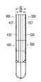
도 1은 본 발명의 바람직한 실시 예에 따른 유리조리용기를 구비한 조리기기의 손잡이가 장착된 것을 개괄적으로 보인 사시도이며;
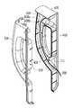
도 2는 본 발명의 바람직한 실시 예에 따른 유리조리용기를 구비한 조리기기의 손잡이의 분해 사시도이며;
도 3은 본 발명의 바람직한 실시 예에 따른 유리조리용기를 구비한 조리기기의 손잡이가 분해된 상태에서의 평면도이며;
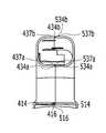
도 4는 본 발명의 바람직한 실시 예에 따른 유리조리용기를 구비한 조리기기의 손잡이가 조립된 상태에서의 배면도이며;
도 5는 본 발명의 바람직한 실시 예에 따른 유리조리용기를 구비한 조리기기의 손잡이가 조립된 상태에서의 평면도이며;
도 6은 본 발명의 바람직한 실시 예에 따른 유리조리용기를 구비한 조리기기의 손잡이가 조립된 상태에서의 횡단면도이며;
도 7은 본 발명의 바람직한 실시 예에 따른 유리조리용기를 구비한 조리기기의 분쇄 조리시 개폐감지용 스위치에 연결된 전기배선의 설치상태를 설명하기 위한 도면이다.BRIEF DESCRIPTION OF THE DRAWINGS FIG. 1 is a perspective view schematically showing a handle of a cooking device provided with a glass cooking container according to a preferred embodiment of the present invention; FIG.
2 is an exploded perspective view of a handle of a cooking appliance provided with a glass cooking vessel according to a preferred embodiment of the present invention;
3 is a plan view of a cooking apparatus having a glass cooking vessel according to a preferred embodiment of the present invention in a state in which a handle is disassembled;
FIG. 4 is a rear view of a cooking device having a glass cooking container according to a preferred embodiment of the present invention, in which a handle is assembled; FIG.
5 is a plan view of a cooking apparatus having a glass cooking vessel according to a preferred embodiment of the present invention in a state in which a handle is assembled;
FIG. 6 is a cross-sectional view of a cooking device having a glass cooking container according to a preferred embodiment of the present invention in a state in which a handle is assembled;
FIG. 7 is a view for explaining an installation state of an electric wiring connected to a switch for detecting opening / closing of a cooking appliance of a cooking device having a glass cooking container according to a preferred embodiment of the present invention.
본 명세서에서 사용되는 용어는 본 발명에서의 기능을 고려하면서 가능한 현재 널리 사용되는 일반적인 용어를 선택하였으나, 이는 당 분야에 종사하는 기술자의 의도 또는 관례 또는 새로운 기술의 출현 등에 따라 달라질 수 있다. 또한, 특정한 경우는 출원인이 임의로 선정한 용어도 있으며, 이 경우 해당되는 발명의 설명 부분에서 그 의미를 기재할 것이다. 따라서 본 명세서에서 사용되는 용어는, 단순한 용어의 명칭이 아닌 그 용어가 가지는 실질적인 의미와 본 명세서의 전반에 걸친 내용을 토대로 해석되어야 함을 밝혀두고자 한다.As used herein, terms used in the present invention are selected from general terms that are widely used in the present invention while taking into account the functions of the present invention, but these may vary depending on the intention or custom of a person skilled in the art or the emergence of new technologies. In addition, in certain cases, there may be a term arbitrarily selected by the applicant, in which case the meaning thereof will be described in the description of the corresponding invention. Therefore, it is intended that the terminology used herein should be interpreted based on the meaning of the term rather than on the name of the term, and on the entire contents of the specification.
도 1은 본 발명의 바람직한 실시 예에 따른 유리조리용기를 구비한 조리기기의 손잡이가 장착된 것을 개괄적으로 보인 사시도이다. 도 1을 참조하면, 유리조리용기를 구비한 조리기기는, 유리 용기부(100)와 본체부(200)으로 구성된다.BRIEF DESCRIPTION OF THE DRAWINGS FIG. 1 is a perspective view schematically showing a handle of a cooking device provided with a glass cooking container according to a preferred embodiment of the present invention. Referring to FIG. 1, a cooking apparatus having a glass cooking vessel includes a
여기서, 유리 용기부(100)는, 조리재료가 투입되기 위한 형상으로 형성되며, 일측 외측면에 손잡이 베이스(111)가 일체형으로 연장 형성되는 유리조리용기(110)와, 유리조리용기(110)의 하단 외주면에 나사결합방식으로 결합되거나 볼팅체결방식으로 체결되는 용기 베이스(bowl base)(120)와; 한 쌍의 좌측 및 우측 손잡이 부재(400,500)가 유리 용기부(110)의 손잡이 베이스(111)를 양측면에서 유리 용기부(100)의 외측면의 형상을 따라 밀착되도록 착탈 및 고정되는 손잡이부(400,500)와; 유리조리용기(110)의 개방된 상부를 개폐하는 덮개부(140)와; 용기 베이스(120)의 밑면에 본체부(200)와 전기적으로 접속을 위해 설치된 접속 플러그(150)와, 유리조리용기(110)의 내부에 조리재료를 분쇄 또는 혼합하기 위해 설치되는 칼날(160)과, 유리조리용기(110)의 밑면에 조리용기(110)를 가열하기 위해 설치된 히터(170)와, 용기 베이스(120)을 중심에 관통 설치되어 상기 칼날(160)에 연결 설치된 상부 커플링(180)으로 구성된다.Here, the
도 2는 본 발명의 바람직한 실시 예에 따른 유리조리용기를 구비한 조리기기의 손잡이의 분해 사시도이며; 도 3은 본 발명의 바람직한 실시 예에 따른 유리조리용기를 구비한 조리기기의 손잡이가 분해된 상태에서의 평면도이다.2 is an exploded perspective view of a handle of a cooking appliance provided with a glass cooking vessel according to a preferred embodiment of the present invention; FIG. 3 is a plan view of a cooking apparatus having a glass cooking vessel according to a preferred embodiment of the present invention in a state in which the handle is disassembled. FIG.
도 2 내지 도 3을 참조하면, 본 발명의 바람직한 실시 예에 따른 유리조리용기를 구비한 조리기기의 손잡이 구조(400,500)는 유리조리용기(110)의 외주면에 대하여 수직방향으로 밀착된 상태를 유지하면서, 유리조리용기(110)의 손잡이 베이스(111)를 감싸도록 양측에서 서로 밀착되면서 체결 및 고정되는 제1 및 제2 손잡이부(400,500)를 포함한다.2 to 3, the
여기서, 제1 및 제2 손잡이부(400,500)는, 좌우대칭구조를 이루도록 서로 밀착되면서 체결되도록, 제1 및 제2 베이스부(410,510)와, 제1 베이스부(410)의 상단부에 일체형으로 형성된 상부판(420)과, 제1 및 제2 베이스부(410,510) 및 상부판(420)과 일체형으로 형성된 제1 및 제2 손잡이관(430,530)으로 구성된다.The first and
여기서, 제1 및 제2 베이스부(410,510)는 좌우대칭구조를 이루도록 서로 밀착되면서 체결되고, 체결된 상태에서 손잡이 베이스(111)가 관통되도록 상단부 및 하단부에 제1 및 제2 상측개구(411,511)와 제1 및 제2 하측개구(413,513)가 각각 형성되며, 유리조리용기(110)의 외주면에 고정된 상태에서 유리조리용기(110)의 외주면과의 사이에 일정한 열감쇠공간(A110)이 형성되도록 외주면을 따라 직각방향으로 절곡된 제1 및 제2 절곡단(417,517)이 횡방향으로 일정 길이 연장 형성되기 때문에 도 5 및 도 7에 도시된 바와 같이, 서로 체결된 제1 또는 제2 베이스(410,510)의 하단면의 횡측길이(d1)는 상단면의 횡측길이(d2) 보다 상대적으로 길게 형성된다.The first and
또한, 상부판(420)은 제1 또는 제2 베이스(410,510)의 상부에 수평방향으로 일체형으로 연장 형성되고, 밑면에 유리조리용기(110)의 개폐를 감지하기 위한 거품감지센서나, 마그네틱 스위치나 마이크로 스위치와 같은 개폐감지용 센서(330)가 고정되도록 장착되는 센서 장착공(421)이 형성되고, 제1 및 제2 베이스부(410,510)가 체결되면 제1 또는 제2 베이스(410,510)의 상부를 덮는다.The
또한, 제1 및 제2 손잡이관(430,530)은 서로 밀착되면서 체결되고, 체결된 상태에서 중심부에 제1 및 제2 파지용 개구(440,540)가 형성되며, 손잡이 베이스(111)가 삽입되는 손잡이 베이스 설치공간(A120)을 형성하면서 제1 및 제2 베이스부(410,510) 및 상부판(420)과 일체형으로 연장 형성되며, 외측 상단부는 제1 및 제2 베이스부(410,510) 및 상부판(420)의 상부에 연결되면서 내측 상단부는 제1 및 제2 상측개구(411,511)와 연결되고, 외측 하단부는 제1 및 제2 베이스부(410,510)의 하부에 연결되면서 내측 하단부는 제1 및 제2 하측개구(413,513)에 연결되고, 제1 상측개구(411)와 제1 하측개구(413)와 접하는 위치에 제1 상부 결합돌기(431) 및 제1 하부 결합돌기(435)가 각각 돌출 형성되고, 제2 상측개구(511)와 제2 하측개구(513)와 접하는 위치에 제2 상부 결합돌기(531) 및 제2 하부 결합돌기(535)가 각각 돌출 형성된다.The first and
또한, 도 4 내지 도 6에 도시된 바와 같이, 제1 손잡이관(430)의 외측 단면에는 제3 단차(434a,434b)가 각각 형성되며, 제2 손잡이관(530)의 외측 단면에도 제4 단차(534a,534b)가 각각 형성되되, 제3 단차(434a,434b)와 제4 단차(534a,534b)의 형상은 ㄱ자 또는 ㄴ자 형상으로 서로 엇갈리는 형상으로 형성되는 것이 바람직하다.4 to 6,
또한, 도 4 내지 도 6에 도시된 바와 같이, 제2 손잡이관(530)의 외측 단면에는 다수개의 제2 착탈편(537a,537b)이 돌출 형성되고, 다수개의 제2 착탈편(537a,537b)에 대응되는 제1 손잡이관(430)의 외측 단면에도 다수개의 제2 착탈홈(437a,437b)이 각각 돌출 형성된다.4 to 6, a plurality of second
여기서, 제1 베이스부(410)의 밑면에는 도 2 및 도 3에 도시된 바와 같이, 횡방향으로 다수개의 일자형의 제1 보강리브(415)가 일정 간격으로 일체형으로 형성되며, 각각의 제1 보강리브(415) 사이에 위치하는 밑면 내측단부에 다수개의 제1 착탈홈(416)이 일정 간격으로 형성되는 반면, 제2 베이스부(510)의 밑면에는 각각의 제1 보강리브(415)와 엇갈리도록 횡방향으로 다수개의 일자형의 제3 보강리브(515)가 일정 간격으로 일체형으로 형성되며, 제2 베이스부(510)의 밑면 내측단부와 각각의 제3 보강리브(515) 사이에 다수개의 제2 착탈편(516)이 외측방향으로 일체형으로 돌출 형성된다. 이에 따라 작업자에 의해 제1 베이스부(410)와 제2 베이스부(510)가 서로 밀착되면서 체결되는 경우, 다수개의 제2 착탈편(516)이 다수개의 제1 착탈홈(416)에 탄성적으로 체결된다.As shown in FIGS. 2 and 3, a plurality of linear first reinforcing
또한, 제1 및 제2 베이스부(410,510)가 좌우대칭구조를 이루도록 서로 밀착될 때, 제1 베이스부(410)의 제1 단차(414)와 제2 베이스부(510)의 제2 단차(514)가 서로 엇갈리면서 밀착되는데, 도 2에 도시된 바와 같이, 본 발명의 바람직한 실시 예에서는 제1 베이스부(410)의 제1 단차(414)는 외면이 밑면 보다 상대적으로 길도록 형성되고, 제2 베이스부(510)의 제2 단차(514)는 외면이 밑면보다 상대적으로 짧게 형성되도록 형성되는 것이 바람직하다.When the first and
또한, 제1 및 제2 베이스부(410,510)가 좌우대칭구조를 이루도록 서로 밀착 및 체결된 상태에서 제1 절곡단(417) 및 제2 절곡단(517)에 대응되는 제1 베이스부(410)의 제1 수직 내주면(412) 및 제2 베이스부(510)의 제2 수직 내주면(512)은 도 2에 도시된 바와 같이, 외측단부로 향할수록 두께가 얇아지도록 형성되는 것이 바람직하다.The
이에 따라 도 4에 도시된 바와 같이, 유리조리용기(110)의 외주면에 고정된 상태에서 제1 절곡단(417) 및 제2 절곡단(517)의 높이에 비례하도록 유리조리용기(110)의 외주면과 제1 및 제2 베이스부(410,510) 사이에 일정한 열감쇠공간(A110)이 형성되어 있어, 유리조리용기(110)의 내부를 가열하는 경우 유리조리용기(110)의 내부에서 발생하는 열이 열감쇠공간(A110)에서 감쇠되어 사용자의 손에 고열의 전달을 방지한다.4, in a state of being fixed to the outer circumferential surface of the
또한, 제1 및 제2 상측개구(411,511)와 인접하는 제1 및 제2 손잡이관(430,530)의 내면에는 도 2 및 도 3에 도시된 바와 같이, 손잡이 베이스(111)의 설치 위치를 가이드 하기 위한 제1 및 제2 상부 가이더(433,533)가 일체형으로 각각 돌출 형성되는데, 제1 및 제2 상부 가이더(433,533)는 손잡이 베이스(111)의 설치 위치를 가이드하면서도, 손잡이 베이스(111)가 설치된 상태에서 유리조리용기(110)의 내부에 들어있는 음식재료를 분쇄할 때 발생하는 진동으로 인한 손잡이 베이스(111)의 흔들림이나 움직임을 방지한다.As shown in FIGS. 2 and 3, on the inner surfaces of the first and
한편, 제1 베이스부(410)의 제1 상부 결합돌기(431) 및 제1 하부 결합돌기(435)의 중심부에는 도 2 및 도 7에 도시된 바와 같이, 일정 깊이로 나사산이 형성된 제1 결합홀(432) 및 제2 결합홀(436)이 각각 형성되며, 제2 베이스부(510)의 제2 상부 결합돌기(531) 및 제2 하부 결합돌기(535)의 중심부에는 일정 깊이로 걸림턱(미도시)이 각각 형성된 제2 결합홀(532)이 관통 형성된다. 이때, 제1 상부 결합돌기(431) 및 제1 하부 결합돌기(435)의 길이는 제2 상부 결합돌기(531) 및 제2 하부 결합돌기(535)의 길이 보다 상대적으로 길게 형성되고, 제1 상부 결합돌기(431) 및 제1 하부 결합돌기(435)의 외경은 제2 상부 결합돌기(531) 및 제2 하부 결합돌기(535)의 내경 보다 작거나 같게 형성된다.2 and 7, at the center of the first
이에 따라 제1 및 제2 손잡이부(400,500)가 서로 체결되는 경우, 제1 베이스부(410)의 제1 상부 결합돌기(431) 및 제1 하부 결합돌기(435)는 제2 베이스부(510)의 제2 상부 결합돌기(531) 및 제2 하부 결합돌기(535)의 내부에 일정 길이 삽입되며, 제2 상부 결합돌기(531) 및 제2 하부 결합돌기(535)의 외측방향에서 삽입되는 고정용 볼트(610,620)를 이용하여 제1 및 제2 손잡이부(400,500)를 서로 고정시킬 수 있다.The first
한편, 제2 손잡이관(530)의 상단부에는 제1 및 제2 손잡이부(400,500)가 체결되는 경우, 센서 장착공(421)을 밑면과 측면을 지지하도록 수납하는 지지공(521)이 일체형으로 형성되기 때문에 유리조리용기(110)의 내부에 들어있는 음식재료를 분쇄할 때 진동이 발생하여도 센서 장착공(421)에 설치된 센서의 흔들림이나 움직임을 방지하여 원래의 설치위치를 유지시킨다.When the first and
또한, 제1 손잡이관(430)의 내측면에는 횡방향으로 U자 형상의 다수개의 제2 보강리브(438)가 일정 간격으로 일체형으로 돌출 형성되며, 각각의 제2 보강리브(438)는 일측 모서리에 각각 형성된 배선 설치용 절단구간(439)을 중심으로 일자 보강리브(438a)와 ㄴ자 형상의 보강리브(438b)가 각각 분리 형성되고, 제2 손잡이관(530)의 내측면에는 횡방향으로 U자 형상의 다수개의 제4 보강리브(538)가 일정 간격으로 일체형으로 돌출 형성된다.A plurality of second reinforcing
이에 따라, 손잡이 베이스(111)의 외측면을 감싸면서 제1 및 제2 손잡이관(430,530)이 서로 체결되는 경우, 손잡이 베이스(111)는 다수개의 제2 보강리브(438)와 다수개의 제4 보강리브(538)의 사이에 설치되며, 각각의 제2 보강리브(438)의 일측 모서리에 각각 형성된 배선 설치용 절단구간(439)에는 센서 장착공(421)에 설치된 센서에 연결된 전기배선(350)이 수직방향으로 장착되기 때문에 유리조리용기(110)의 내부에 들어있는 음식재료를 분쇄할 때 진동이 발생하여도 배선 설치용 절단구간(439)에 설치된 전기배선(350)의 흔들림이나 움직임을 방지할 수 있다.Accordingly, when the first and
이상에서 설명한 바와 같이, 본 발명의 바람직한 실시 예에 따른 유리조리용기를 구비한 조리기기의 손잡이 구조(400,500)는 (1)제1 베이스부(410)의 제1 단차(414)와 제2 베이스부(510)의 제2 단차(514)가 서로 어긋나게 밀착되는 동시에 제1 손잡이관(430)의 제3 단차(434a,434b)와 제2 손잡이관(530)의 제4 단차(534a,534b)가 서로 어긋나게 밀착되면, (2)제2 베이스(510)의 제1 착탈편(516)이 제1 베이스(410)의 제1 착탈홈(416)에 각각 체결되는 동시에 제2 손잡이관(530)의 제2 착탈편(537a,537b) 또한 제1 손잡이관(430)의 제2 착탈홈(437a,437b)에 각각 체결되며, (3) 작업자에 의해 고정용 볼트(610,620)가 제2 상부 결합돌기(531) 및 제2 하부 결합돌기(535)의 외측방향에서 삽입되어 나사산이 각각 형성된 제1 상부 결합돌기(431)의 제1 결합홀(432) 및 제1 하부 결합돌기(435)의 제2 결합홀(436)에 일정 깊이로 고정되는 방식으로 고정된다.As described above, the
이상에서는 본 발명의 바람직한 실시 예에 대하여 도시하고 설명하였지만, 본 발명은 상술한 특정의 실시 예에 한정되지 아니하며, 청구범위에서 청구하는 본 발명의 요지를 벗어남이 없이 당해 발명이 속하는 기술분야에서 통상의 지식을 가진자에 의해 다양한 변형실시가 가능한 것은 물론이고, 이러한 변형실시들은 본 발명의 기술적 사상이나 전망으로부터 개별적으로 이해돼서는 안 될 것이다.While the present invention has been particularly shown and described with reference to exemplary embodiments thereof, it is clearly understood that the same is by way of illustration and example only and is not to be construed as limiting the scope of the invention as defined by the appended claims. It will be understood by those skilled in the art that various changes in form and details may be made therein without departing from the spirit and scope of the present invention.
400 : 제1 손잡이부410 : 제1 베이스부
411 : 제1 상측개구412 : 제1 수직내주면
413 : 제1 하측개구414 : 제1 단차
415 : 제1 보강리브416 : 제1 착탈홈
417 : 제1 절곡단419 : 제1 고정돌기
420 : 상부판421 : 센서 장착공
430 : 제1 손잡이관431 : 제1 상부 결합돌기
432 : 결합홀433 : 제1 상부 가이더
434a,434b : 제2 단차435 : 제1 하부 결합돌기
436 : 결합홀437a,437b : 제2 착탈홈
438,438a,438b : 제2 보강리브439 : 절단구간
440 : 제1 파지용 개구
500 : 좌측 몸체부510 : 제2 베이스부
511 : 제2 상측개구512 : 제2 수직내주면
513 : 제2 하측개구514 : 제3 단차
515 : 제3 보강리브516 : 제1 착탈편
517 : 제2 절곡단519 : 제2 고정돌기
521 : 지지공530 : 제2 손잡이관
531 : 제2 상부 결합돌기532 : 결합홀
533 : 제2 상부 가이더534a,534b : 제3 단차
535 : 제2 하부 결합돌기536 : 결합홀
537a,537b : 제2 착탈편538 : 제4 보강리브
540 : 제2 파지용 개구350 : 전기배선
610,620 : 고정용 볼트 A110 : 열 감쇠공간
A120 : 손잡이베이스 설치공간400: first handle portion 410: first base portion
411: first upper opening 412: first vertical inner peripheral surface
413: first lower opening 414: first step
415: first reinforcing rib 416: first detaching groove
417: first bending stage 419: first fixing projection
420: upper plate 421: sensor mounting hole
430: first handle tube 431: first upper engaging projection
432: coupling hole 433: first upper guider
434a, 434b: second step 435: first lower coupling projection
436: engaging
438, 438a, 438b: second reinforcing rib 439:
440: opening for the first holding
500: left body part 510: second base part
511: second upper side opening 512: second vertical inner peripheral surface
513: second lower opening 514: third step
515: third reinforcing rib 516: first detachment piece
517: second bending stage 519: second fixing projection
521: support ball 530: second handle tube
531: second upper engaging projection 532: engaging hole
533: second
535: second lower engaging projection 536: engaging hole
537a, 537b: second detachable piece 538: fourth reinforcing rib
540: opening for the second holding 350: electric wiring
610,620: Fixing Bolt A110: Heat Decay Space
A120: Installation space of handle base
Claims (7)
Translated fromKorean상기 손잡이 구조는, 상기 유리조리용기(110)의 외주면에 대하여 수직방향으로 밀착된 상태를 유지하면서, 상기 유리조리용기(110)의 손잡이 베이스(111)를 감싸도록 양측에서 서로 밀착되면서 체결 및 고정되는 제1 및 제2 손잡이부(400,500)를 포함하며;
상기 제1 및 제2 손잡이부(400,500)는,
좌우대칭구조를 이루도록 서로 밀착되면서 체결되고, 체결된 상태에서 상기 손잡이 베이스(111)가 관통되도록 상단부 및 하단부에 제1 및 제2 상측개구(411,511)와 제1 및 제2 하측개구(413,513)가 각각 형성되며, 상기 유리조리용기(110)의 외주면에 고정된 상태에서 상기 유리조리용기(110)의 외주면과의 사이에 일정한 열감쇠공간(A100)이 형성되도록 외주면을 따라 직각방향으로 절곡된 제1 및 제2 절곡단(417,517)이 횡방향으로 일정 길이 연장 형성되는 제1 및 제2 베이스부(410,510)와;
상기 제1 또는 제2 베이스(410,510)의 상부에 수평방향으로 일체형으로 연장 형성되고, 밑면에 상기 유리조리용기(110)의 개폐를 감지하기 위한 온도감지용 또는 개폐감지용 센서가 고정되도록 장착되는 센서 장착공(421)이 형성되고, 상기 제1 및 제2 베이스부(410,510)가 체결되면 상기 제1 또는 제2 베이스(410,510)의 상부를 덮는 상부판(420)과;
서로 밀착되면서 체결되고, 체결된 상태에서 중심부에 제1 및 제2 파지용 개구(440,540)가 형성되며, 상기 손잡이 베이스(111)가 삽입되는 손잡이 베이스 설치공간(A120)을 형성하면서 상기 제1 및 제2 베이스부(410,510) 및 상부판(420)과 일체형으로 연장 형성되며, 상기 제1 상측개구(411)와 제1 하측개구(413)와 접하는 위치에 제1 상부 결합돌기(431) 및 제1 하부 결합돌기(435)가 각각 돌출 형성되고, 상기 제2 상측개구(511)와 제2 하측개구(513)와 접하는 위치에 제2 상부 결합돌기(531) 및 제2 하부 결합돌기(535)가 각각 돌출 형성되는 제1 및 제2 손잡이관(430,530)으로 구성되며;
상기 제1 손잡이관(430)의 내측면에는 횡방향으로 U자 형상의 다수개의 제2 보강리브(438)가 일정 간격으로 일체형으로 돌출 형성되며, 상기 각각의 제2 보강리브(438)의 일측 모서리에 각각 형성된 배선 설치용 절단구간(439)을 중심으로 일자 보강리브(438a)와 ㄴ자 형상의 보강리브(438b)가 각각 분리 형성되고;
상기 제2 손잡이관(530)의 내측면에는 횡방향으로 U자 형상의 다수개의 제4 보강리브(538)가 일정 간격으로 일체형으로 돌출 형성되는 것을 특징으로 유리조리용기를 구비한 조리기기의 손잡이 구조.In a handle structure of a cooking appliance in which at least one pair of knob bases (111) are integrally extended on one side outer surface of a glass cooking container (110)
The handle structure is tightly fixed on both sides so as to enclose the handle base 111 of the glass cooking container 110 while maintaining a state in which the handle structure is in a state of being vertically contacted with the outer peripheral surface of the glass cooking container 110, The first and second handle portions (400, 500);
The first and second handle portions 400,
The first and second upper openings 411 and 511 and the first and second lower openings 413 and 513 are formed at the upper and lower ends so that the handle base 111 penetrates through the first and second upper openings 411 and 511, And is bent in a direction perpendicular to the outer circumferential surface so as to form a constant heat attenuation space A100 between the outer circumferential surface of the glass cooking container 110 and the outer circumferential surface of the glass cooking container 110 while being fixed to the outer circumferential surface of the glass cooking container 110. [ First and second base portions 410 and 510 having first and second bent ends 417 and 517 extending in a transverse direction by a predetermined length;
A temperature sensing or opening / closing sensing sensor for sensing the opening / closing of the glass cooking container 110 is fixedly installed on the bottom of the first or second base 410 or 510, An upper plate 420 having a sensor mounting hole 421 and covering an upper portion of the first or second base 410 and 510 when the first and second base portions 410 and 510 are fastened;
The first and second gripping openings 440 and 540 are formed at the central portion in the state of being tightly coupled with each other while the handle base mounting space A 120 into which the handle base 111 is inserted is formed, A first upper coupling protrusion 431 and a second upper coupling protrusion 433 are formed at a position in contact with the first upper opening 411 and the first lower opening 413 and integrally formed with the second base portions 410, And a second upper coupling protrusion 531 and a second lower coupling protrusion 535 are formed at positions where the second upper opening 511 and the second lower opening 513 are in contact with each other. And the first and second grip pipes 430 and 530 are protruded from the first and second grip pipes 430 and 530, respectively.
A plurality of second reinforcing ribs 438 having a U-shape in the transverse direction are integrally protruded from the inner surface of the first handle pipe 430 at predetermined intervals, and one side of each second reinforcing rib 438 The dagger reinforcing ribs 438a and the 棺 -shaped reinforcing ribs 438b are formed separately from each other around the cutting section 439 for wiring installation formed at each corner;
A plurality of U-shaped fourth reinforcing ribs 538 are integrally protruded from the inner surface of the second handle pipe 530 at regular intervals. The handle of the cooking apparatus with the glass cooking container, rescue.
상기 제1 베이스부(410)의 밑면에는 횡방향으로 다수개의 일자형의 제1 보강리브(415)가 일정 간격으로 일체형으로 형성되며, 상기 각각의 제1 보강리브(415) 사이에 위치하는 밑면 내측단부에 다수개의 제1 착탈홈(416)이 일정 간격으로 형성되며;
상기 제2 베이스부(510)의 밑면에는 상기 각각의 제1 보강리브(415)와 엇갈리도록 횡방향으로 다수개의 일자형의 제3 보강리브(515)가 일정 간격으로 일체형으로 형성되며, 상기 제2 베이스부(510)의 밑면 내측단부와 상기 각각의 제3 보강리브(515) 사이에 다수개의 제2 착탈편(516)이 외측방향으로 일체형으로 돌출 형성되며;
상기 제1 베이스부(410)와 상기 제2 베이스부(510)가 서로 밀착되면서 체결되는 경우, 상기 다수개의 제2 착탈편(516)이 상기 다수개의 제1 착탈홈(416)에 탄성적으로 체결되는 것을 특징으로 유리조리용기를 구비한 조리기기의 손잡이 구조.The method according to claim 1,
A plurality of linear first reinforcing ribs 415 are integrally formed on the bottom surface of the first base portion 410 at predetermined intervals in the transverse direction and a plurality of first reinforcing ribs 415 are formed on the bottom surface inside the first reinforcing ribs 415, A plurality of first detachable grooves 416 are formed at regular intervals at an end thereof;
A plurality of linear third reinforcing ribs 515 are integrally formed on the bottom surface of the second base portion 510 at predetermined intervals in a transverse direction so as to be offset from the first reinforcing ribs 415, A plurality of second detachable pieces 516 protrude integrally outwardly between the inner end of the bottom surface of the base portion 510 and each of the third reinforcing ribs 515;
When the first base part 410 and the second base part 510 are tightly coupled to each other, the plurality of second detachable pieces 516 are resiliently attached to the plurality of first detachable grooves 416 Wherein the glass container is fastened to the glass container.
상기 제1 및 제2 상측개구(411,511)와 인접하는 상기 제1 및 제2 손잡이관(430,530)의 내면에는 상기 손잡이 베이스(111)의 설치 위치를 가이드 하기 위한 제1 및 제2 상부 가이더(433,533)가 일체형으로 각각 돌출 형성되는 것을 특징으로 유리조리용기를 구비한 조리기기의 손잡이 구조.The method according to claim 1,
The first and second upper guiders 433 and 533 for guiding the mounting position of the pull base 111 are formed on the inner surfaces of the first and second handle pipes 430 and 530 adjacent to the first and second upper side openings 411 and 511, ) Are integrally protruded from each other. The handle structure of a cooking appliance provided with a glass cooking container.
상기 제1 상부 결합돌기(431) 및 제1 하부 결합돌기(435)의 중심부에는 일정 깊이로 나사산이 형성된 제1 결합홀(432) 및 제2 결합홀(436)이 각각 형성되며,
상기 제2 상부 결합돌기(531) 및 제2 하부 결합돌기(535)의 중심부에는 일정 깊이로 걸림턱이 각각 형성된 제2 결합홀(532)이 관통 형성되며,
상기 제1 상부 결합돌기(431) 및 제1 하부 결합돌기(435)의 길이는 상기 제2 상부 결합돌기(531) 및 제2 하부 결합돌기(535)의 길이 보다 상대적으로 길게 형성되고,
상기 제1 상부 결합돌기(431) 및 제1 하부 결합돌기(435)의 외경은 상기 제2 상부 결합돌기(531) 및 제2 하부 결합돌기(535)의 내경 보다 작거다 같아서 상기 제1 및 제2 손잡이부(400,500)가 서로 체결되는 경우 상기 제1 상부 결합돌기(431) 및 제1 하부 결합돌기(435)는 상기 제2 상부 결합돌기(531) 및 제2 하부 결합돌기(535)의 내부에 일정 길이 삽입되며, 상기 제2 상부 결합돌기(531) 및 제2 하부 결합돌기(535)의 외측방향에서 삽입되는 고정용 볼트(610,620)를 이용하여 상기 제1 및 제2 손잡이부(400,500)를 서로 고정시킬 수 있는 것을 특징으로 유리조리용기를 구비한 조리기기의 손잡이 구조.The method according to claim 1,
A first coupling hole 432 and a second coupling hole 436 are formed at the center of the first upper coupling protrusion 431 and the first lower coupling protrusion 435,
The second upper coupling protrusion 531 and the second lower coupling protrusion 535 have a second coupling hole 532 through which a locking protrusion is formed at a predetermined depth,
The length of the first upper coupling protrusion 431 and the first lower coupling protrusion 435 is longer than the length of the second upper coupling protrusion 531 and the second lower coupling protrusion 535,
The outer diameter of the first upper coupling protrusion 431 and the first lower coupling protrusion 435 is smaller than the inner diameter of the second upper coupling protrusion 531 and the second lower coupling protrusion 535, The first upper coupling protrusion 431 and the first lower coupling protrusion 435 are inserted into the second upper coupling protrusion 531 and the second lower coupling protrusion 535 in a state where the two knobs 400 and 500 are fastened to each other, And the fixing bolts 610 and 620 inserted in the outer sides of the second upper coupling protrusions 531 and the second lower coupling protrusions 535 are inserted into the first and second knobs 400 and 500, Wherein the glass cooking vessel is provided with a glass cooking vessel.
상기 제2 손잡이관(530)의 상단부에는 상기 제1 및 제2 손잡이부(400,500)가 체결되는 경우, 상기 센서 장착공(421)을 밑면과 측면을 지지하도록 수납하는 지지공(521)이 일체형으로 형성된 것을 특징으로 유리조리용기를 구비한 조리기기의 손잡이 구조.The method according to claim 1,
When the first and second knobs 400 and 500 are fastened to the upper end of the second handle pipe 530, the support hole 521 for receiving the sensor mounting hole 421 to support the bottom surface and the side surface is integrally formed Wherein the handle of the cooking appliance is provided with a glass cooking container.
상기 손잡이 베이스(111)의 외측면을 감싸면서 제1 및 제2 손잡이관(430,530)이 서로 체결되는 경우, 상기 손잡이 베이스(111)는 상기 다수개의 제2 보강리브(438)와 다수개의 제4 보강리브(538)의 사이에 설치되며, 상기 각각의 제2 보강리브(438)의 일측 모서리에 각각 형성된 배선 설치용 절단구간(439)에는 상기 센서 장착공(421)에 설치된 센서에 연결된 전기배선(350)이 수직방향으로 장착되는 것을 특징으로 유리조리용기를 구비한 조리기기의 손잡이 구조.The method according to claim 1,
When the first and second handle pipes 430 and 530 are fastened together while covering the outer surface of the handle base 111, the handle base 111 is fixed to the plurality of second reinforcing ribs 438 and the plurality of fourth The electric wiring (not shown) connected to the sensor provided in the sensor mounting hole 421 is provided in the wiring cut-off section 439 formed between the reinforcing ribs 538 and formed at one side edge of each of the second reinforcing ribs 438 350) are mounted in a vertical direction. The handle structure of a cooking appliance provided with a glass cooking container.
상기 제1 및 제2 손잡이관(430,530)의 외측 상단부는 상기 제1 및 제2 베이스부(410,510) 및 상부판(420)의 상부에 연결되면서, 내측 상단부는 제1 및 제2 상측개구(411,511)와 연결되고,
외측 하단부는 상기 제1 및 제2 베이스부(410,510)의 하부에 연결되면서, 내측 하단부는 상기 제1 및 제2 하측개구(413,513)에 연결되는 것을 특징으로 유리조리용기를 구비한 조리기기의 손잡이 구조.The method according to claim 1,
The outer upper ends of the first and second handle pipes 430 and 530 are connected to the upper portions of the first and second base portions 410 and 510 and the upper plate 420 while the inner upper ends thereof are connected to the first and second upper openings 411 and 511 Respectively,
The outer lower end of the first and second base portions 410 and 510 is connected to the lower portion of the first and second base portions 410 and 510 while the inner lower end portion is connected to the first and second lower openings 413 and 513, rescue.
Priority Applications (4)
| Application Number | Priority Date | Filing Date | Title |
|---|---|---|---|
| PCT/KR2017/007785WO2018016880A1 (en) | 2016-07-19 | 2017-07-19 | Cooking device having cooking glass bowl and handle structure thereof |
| US16/094,327US11058253B2 (en) | 2016-07-19 | 2017-07-19 | Cooking device having cooking glass bowl and handle structure thereof |
| KR1020170091273AKR101826760B1 (en) | 2017-07-19 | 2017-07-19 | Handle structure of a cooker having a glass cooking vessel |
| JP2019524103AJP6735920B2 (en) | 2016-07-19 | 2017-07-19 | Structure of cooking equipment with glass cooking container and handle thereof |
Applications Claiming Priority (1)
| Application Number | Priority Date | Filing Date | Title |
|---|---|---|---|
| KR1020170091273AKR101826760B1 (en) | 2017-07-19 | 2017-07-19 | Handle structure of a cooker having a glass cooking vessel |
Publications (1)
| Publication Number | Publication Date |
|---|---|
| KR101826760B1true KR101826760B1 (en) | 2018-02-07 |
Family
ID=60992293
Family Applications (1)
| Application Number | Title | Priority Date | Filing Date |
|---|---|---|---|
| KR1020170091273AActiveKR101826760B1 (en) | 2016-07-19 | 2017-07-19 | Handle structure of a cooker having a glass cooking vessel |
Country Status (4)
| Country | Link |
|---|---|
| US (1) | US11058253B2 (en) |
| JP (1) | JP6735920B2 (en) |
| KR (1) | KR101826760B1 (en) |
| WO (1) | WO2018016880A1 (en) |
Cited By (1)
| Publication number | Priority date | Publication date | Assignee | Title |
|---|---|---|---|---|
| KR102467993B1 (en) | 2021-11-16 | 2022-11-17 | 주식회사 로닉 | Handle for glass cooking device |
Families Citing this family (24)
| Publication number | Priority date | Publication date | Assignee | Title |
|---|---|---|---|---|
| CN110250947B (en)* | 2018-03-22 | 2022-03-15 | 九阳股份有限公司 | A visual food processor |
| CN108652407A (en)* | 2018-06-13 | 2018-10-16 | 深圳市凝锐电子科技有限公司 | A kind of separate type juice extractor |
| US12145118B2 (en)* | 2018-12-19 | 2024-11-19 | Revelution Technology, Llc | Self-blending bottle |
| DE202019100726U1 (en)* | 2019-02-08 | 2019-02-21 | De'longhi Braun Household Gmbh | Container with universal invisible handle attachment for use with household appliances |
| USD897758S1 (en)* | 2019-03-05 | 2020-10-06 | Capbran Holdings, Llc | Blender with vessel |
| AU2020245708A1 (en)* | 2019-03-25 | 2021-09-23 | Breville Pty Limited | Kitchen device |
| CN114206180A (en) | 2019-05-28 | 2022-03-18 | 尚科宁家运营有限公司 | Heated food processor |
| US20210022555A1 (en)* | 2019-07-25 | 2021-01-28 | Columbia Insurance Company | Variable Temperature Blender |
| AU2020362573B2 (en)* | 2019-10-07 | 2023-10-19 | Lg Electronics Inc. | Blender |
| DE102019134095A1 (en)* | 2019-12-12 | 2021-06-17 | Vorwerk & Co. Interholding Gmbh | Hotplate module for connecting to a kitchen appliance base and cooking system |
| CN111166158B (en)* | 2019-12-31 | 2021-10-15 | 广东美的厨房电器制造有限公司 | cooking equipment |
| US11344157B2 (en)* | 2020-05-08 | 2022-05-31 | Capbran Holdings, Llc | Blender and food processor combination with safety features |
| USD929177S1 (en)* | 2020-07-24 | 2021-08-31 | Capbran Holdings, Llc | Blender |
| USD929176S1 (en)* | 2020-07-24 | 2021-08-31 | Capbran Holdings, Llc | Blender |
| US11241119B2 (en) | 2020-07-27 | 2022-02-08 | Sharkninja Operating Llc | Container for food processing system |
| USD956471S1 (en) | 2020-10-22 | 2022-07-05 | Sharkninja Operating Llc | Blender base |
| USD999020S1 (en) | 2020-10-22 | 2023-09-19 | Sharkninja Operating Llc | Blender container |
| USD982971S1 (en) | 2020-10-22 | 2023-04-11 | Sharkninja Operating Llc | Blade holder |
| USD984210S1 (en) | 2020-10-22 | 2023-04-25 | Sharkninja Operating Llc | Blender container |
| CN112617631B (en)* | 2020-12-01 | 2023-01-10 | 山东省十里香芝麻制品股份有限公司 | Infant sesame powder grinding device |
| CN216439007U (en)* | 2020-12-30 | 2022-05-06 | 杭州九阳小家电有限公司 | Liquid heater |
| US11172786B2 (en) | 2021-02-18 | 2021-11-16 | Sharkninja Operating Llc | Container for food processing system |
| DE102021114057A1 (en)* | 2021-05-31 | 2022-12-01 | Vorwerk & Co. Interholding Gesellschaft mit beschränkter Haftung | Juicer insert for a preparation vessel and food processor with juicer insert |
| CN113566492A (en)* | 2021-08-10 | 2021-10-29 | 青岛海尔电冰箱有限公司 | Water storage devices and refrigerators |
Citations (1)
| Publication number | Priority date | Publication date | Assignee | Title |
|---|---|---|---|---|
| KR200385426Y1 (en)* | 2005-03-14 | 2005-05-27 | (주)유티피전자 | food mixer |
Family Cites Families (22)
| Publication number | Priority date | Publication date | Assignee | Title |
|---|---|---|---|---|
| JPS575121U (en) | 1980-06-06 | 1982-01-11 | ||
| KR890005106Y1 (en)* | 1985-08-16 | 1989-08-02 | 홍기상 | Safety switch device of electric blender |
| KR900004694Y1 (en) | 1987-08-31 | 1990-05-25 | 허만국 | Bypass valve for pump |
| JP2590353Y2 (en)* | 1992-11-30 | 1999-02-10 | 株式会社吉野工業所 | Handle mounting structure for synthetic resin containers |
| US5613274A (en)* | 1995-07-21 | 1997-03-25 | Newell Operating Company | Insulated handle grip |
| DE20213146U1 (en)* | 2002-08-27 | 2002-11-21 | Eupa International Corp., Las Vegas, Nev. | Mixer with an upper cover, which is provided with a switch operating block |
| EP1396220A1 (en)* | 2002-09-04 | 2004-03-10 | Newway Electrical Industries Limited | Improvements in and relating to food processors |
| FR2856910B1 (en) | 2003-07-02 | 2005-08-19 | Seb Sa | HOUSEHOLD APPLIANCE FOR FOOD PREPARATION COMPRISING AN IMPROVED HANDLE |
| JP2009112546A (en) | 2007-11-07 | 2009-05-28 | Sanyo Electric Co Ltd | Electric cooker |
| CN201445383U (en) | 2009-07-15 | 2010-05-05 | 罗全恩 | Automatic power-off protection device used in opening cover of multifunctional household food processor |
| JP5509439B2 (en) | 2010-05-25 | 2014-06-04 | 象印マホービン株式会社 | Electric cooker |
| KR101215223B1 (en)* | 2010-06-17 | 2012-12-24 | 양원준 | A detachable handle for cooking vessels |
| KR101183239B1 (en)* | 2010-12-30 | 2012-09-14 | 김홍배 | Automatic Cooker Having Improved Heating and Sealing |
| KR101216942B1 (en)* | 2011-07-18 | 2012-12-28 | 김홍배 | Automatic cook with enhanced safety |
| CN202537098U (en)* | 2012-03-23 | 2012-11-21 | 永庆国际有限公司 | Food processor with safety protection mechanism |
| FR3003457B1 (en) | 2013-03-22 | 2015-11-13 | Seb Sa | ELECTRIC CULINARY PREPARATION APPARATUS WITH WORK CONTAINER |
| US9089238B2 (en)* | 2013-10-10 | 2015-07-28 | Uni-Splender Corp. | Soup maker |
| CN203506474U (en) | 2013-10-11 | 2014-04-02 | 大统营实业股份有限公司 | Stirring soup making machine |
| US9555384B2 (en) | 2013-10-25 | 2017-01-31 | Whirlpool Corporation | Blender assembly |
| KR101432704B1 (en) | 2013-12-19 | 2014-08-25 | 최은성 | food cooking utensils |
| CN204618000U (en) | 2015-05-11 | 2015-09-09 | 顾宣丰 | An electric heating cooking machine mixing cup |
| JP6336205B2 (en)* | 2015-10-12 | 2018-06-06 | コーニンクレッカ フィリップス エヌ ヴェKoninklijke Philips N.V. | Blender with temperature sensor |
- 2017
- 2017-07-19KRKR1020170091273Apatent/KR101826760B1/enactiveActive
- 2017-07-19USUS16/094,327patent/US11058253B2/enactiveActive
- 2017-07-19WOPCT/KR2017/007785patent/WO2018016880A1/ennot_activeCeased
- 2017-07-19JPJP2019524103Apatent/JP6735920B2/enactiveActive
Patent Citations (1)
| Publication number | Priority date | Publication date | Assignee | Title |
|---|---|---|---|---|
| KR200385426Y1 (en)* | 2005-03-14 | 2005-05-27 | (주)유티피전자 | food mixer |
Cited By (1)
| Publication number | Priority date | Publication date | Assignee | Title |
|---|---|---|---|---|
| KR102467993B1 (en) | 2021-11-16 | 2022-11-17 | 주식회사 로닉 | Handle for glass cooking device |
Also Published As
| Publication number | Publication date |
|---|---|
| US20190117013A1 (en) | 2019-04-25 |
| JP6735920B2 (en) | 2020-08-05 |
| US11058253B2 (en) | 2021-07-13 |
| WO2018016880A1 (en) | 2018-01-25 |
| JP2019525821A (en) | 2019-09-12 |
Similar Documents
| Publication | Publication Date | Title |
|---|---|---|
| KR101826760B1 (en) | Handle structure of a cooker having a glass cooking vessel | |
| KR101829813B1 (en) | Cooking device having glass container | |
| KR101817780B1 (en) | Cooking vessel with supersonic vibrator | |
| EP3021720B1 (en) | Blender | |
| US9084508B2 (en) | Kitchen appliance for processing foodstuff and method of operating same | |
| US20150044344A1 (en) | Method and apparatus for using a blender with noise damping elements | |
| CN109222688B (en) | Food processing cooking device | |
| EP3302198B1 (en) | Grinder attachment for blender system | |
| KR100443582B1 (en) | Household food preparation appliance such as a multi-function food processor comprising a bearing means for the rotary working assembly | |
| RU2750451C2 (en) | Cooking machine | |
| US20090000494A1 (en) | Household soybean milk and tofu maker | |
| CN112272530B (en) | Security system for kitchen appliance, method for selecting operation mode and cover | |
| JP2021517016A (en) | Controlled positioning within the food processor | |
| KR102112582B1 (en) | Fixing Type Handle for cooking vessel and cooking vessel with thereof | |
| CN109152500B (en) | Cooking device with glass cooking bowl and handle structure thereof | |
| KR101833279B1 (en) | Internal tightening and contact Cookware | |
| CN210124596U (en) | Cooking utensil | |
| KR102351746B1 (en) | Portable cooking device | |
| KR101157337B1 (en) | Automatic Cooker Having Improved Sanitation Property | |
| KR102313144B1 (en) | Portable cooking device | |
| CN210810662U (en) | Heat insulation type container fixing assembly and kitchen appliance | |
| KR102467993B1 (en) | Handle for glass cooking device | |
| KR20150048614A (en) | Multi-functional processing machine | |
| KR101401507B1 (en) | Multi-functional processing machine | |
| KR100742609B1 (en) | Food Cooker with Detachable Mesh Cover |
Legal Events
| Date | Code | Title | Description |
|---|---|---|---|
| PA0109 | Patent application | Patent event code:PA01091R01D Comment text:Patent Application Patent event date:20170719 | |
| PA0201 | Request for examination | ||
| PA0302 | Request for accelerated examination | Patent event date:20170731 Patent event code:PA03022R01D Comment text:Request for Accelerated Examination Patent event date:20170719 Patent event code:PA03021R01I Comment text:Patent Application | |
| PE0902 | Notice of grounds for rejection | Comment text:Notification of reason for refusal Patent event date:20170907 Patent event code:PE09021S01D | |
| E701 | Decision to grant or registration of patent right | ||
| PE0701 | Decision of registration | Patent event code:PE07011S01D Comment text:Decision to Grant Registration Patent event date:20180124 | |
| GRNT | Written decision to grant | ||
| PR0701 | Registration of establishment | Comment text:Registration of Establishment Patent event date:20180201 Patent event code:PR07011E01D | |
| PR1002 | Payment of registration fee | Payment date:20180202 End annual number:3 Start annual number:1 | |
| PG1601 | Publication of registration | ||
| J206 | Request for trial to confirm the scope of a patent right | ||
| PJ0206 | Trial to confirm the scope of a patent | Patent event code:PJ02062R01D Patent event date:20190520 Comment text:Request for Trial Patent event code:PJ02061E01I Patent event date:20180201 Comment text:Registration of Establishment Decision date:20190930 Request date:20190520 Appeal identifier:2019100001527 Appeal kind category:Confirmation of the scope of right_affirmative | |
| J204 | Request for invalidation trial [patent] | ||
| PJ0204 | Invalidation trial for patent | Patent event date:20190904 Comment text:Request for Trial Patent event code:PJ02042R01D Patent event date:20180201 Comment text:Registration of Establishment Patent event code:PJ02041E01I Appeal kind category:Invalidation Request date:20190904 Decision date:20200826 Appeal identifier:2019100002857 | |
| J301 | Trial decision | Free format text:TRIAL NUMBER: 2019100001527; TRIAL DECISION FOR CONFIRMATION OF THE SCOPE OF RIGHT_AFFIRMATIVE REQUESTED 20190520 Effective date:20190930 | |
| PJ1301 | Trial decision | Patent event code:PJ13011S02D Patent event date:20190930 Comment text:Trial Decision for Confirmation of the Scope of a Right (Patent, Utility Model, Industrial Design) Appeal kind category:Confirmation of the scope of right_affirmative Request date:20190520 Decision date:20190930 Appeal identifier:2019100001527 | |
| PJ2001 | Appeal | Patent event date:20190930 Comment text:Trial Decision for Confirmation of the Scope of a Right (Patent, Utility Model, Industrial Design) Patent event code:PJ20011S02I Appeal kind category:Confirmation of the scope of right_affirmative Decision date:20200904 Appeal identifier:2019200000220 Request date:20191120 | |
| J301 | Trial decision | Free format text:TRIAL NUMBER: 2019100002857; TRIAL DECISION FOR INVALIDATION REQUESTED 20190904 Effective date:20200826 | |
| PJ1301 | Trial decision | Patent event code:PJ13011S05D Patent event date:20200826 Comment text:Trial Decision on Invalidation (Patent, Utility Model, Industrial Design) Appeal kind category:Invalidation Request date:20190904 Decision date:20200826 Appeal identifier:2019100002857 | |
| PJ2002 | Appeal before the supreme court | Comment text:Trial Decision on Invalidation (Patent, Utility Model, Industrial Design) Patent event date:20200826 Patent event code:PJ20021S05I Comment text:Trial Decision for Confirmation of the Scope of a Right (Patent, Utility Model, Industrial Design) Patent event date:20190930 Patent event code:PJ20021S02I Request date:20200924 Appeal identifier:2020300011455 Appeal kind category:Confirmation of the scope of right_affirmative Decision date:20201112 | |
| J302 | Written judgement (patent court) | Free format text:TRIAL NUMBER: 2019200000220; JUDGMENT (PATENT COURT) FOR CONFIRMATION OF THE SCOPE OF RIGHT_AFFIRMATIVE REQUESTED 20191120 Effective date:20200904 | |
| PJ1302 | Judgment (patent court) | Patent event date:20201103 Comment text:Written Judgment (Patent Court) Patent event code:PJ13021S01D Request date:20191120 Decision date:20200904 Appeal identifier:2019200000220 Appeal kind category:Confirmation of the scope of right_affirmative | |
| J303 | Written judgement (supreme court) | Free format text:TRIAL NUMBER: 2020300011455; JUDGMENT (SUPREME COURT) FOR CONFIRMATION OF THE SCOPE OF RIGHT_AFFIRMATIVE REQUESTED 20200924 Effective date:20201112 | |
| PJ1303 | Judgment (supreme court) | Comment text:Written Judgment (Supreme Court) Patent event date:20201123 Patent event code:PJ13031S01D Decision date:20201112 Appeal kind category:Confirmation of the scope of right_affirmative Request date:20200924 Appeal identifier:2020300011455 | |
| PJ2201 | Remand (intellectual property tribunal) | Request date:20201123 Appeal kind category:Confirmation of the scope of right_affirmative Appeal identifier:2020130000176 Decision date:20201217 | |
| PG1701 | Publication of correction | Publication date:20201203 | |
| J301 | Trial decision | Free format text:TRIAL NUMBER: 2020130000176; TRIAL DECISION FOR CONFIRMATION OF THE SCOPE OF RIGHT_AFFIRMATIVE REQUESTED 20201123 Effective date:20201217 | |
| PJ1301 | Trial decision | Patent event code:PJ13011S09D Patent event date:20201217 Comment text:Trial Decision on Final Judgment on Revocation Appeal kind category:Confirmation of the scope of right_affirmative Request date:20201123 Decision date:20201217 Appeal identifier:2020130000176 | |
| PR1001 | Payment of annual fee | Payment date:20201229 Start annual number:4 End annual number:4 | |
| PR1001 | Payment of annual fee | Payment date:20220103 Start annual number:5 End annual number:5 | |
| PR1001 | Payment of annual fee | Payment date:20221219 Start annual number:6 End annual number:6 | |
| J206 | Request for trial to confirm the scope of a patent right | ||
| PJ0206 | Trial to confirm the scope of a patent | Patent event code:PJ02062R01D Patent event date:20230723 Comment text:Request for Trial Patent event code:PJ02061E01I Patent event date:20180201 Comment text:Registration of Establishment Request date:20230723 Appeal identifier:2023100002497 Appeal kind category:Confirmation of the scope of right_defensive | |
| J301 | Trial decision | Free format text:TRIAL NUMBER: 2023100002497; TRIAL DECISION FOR CONFIRMATION OF THE SCOPE OF RIGHT_DEFENSIVE REQUESTED 20230723 Effective date:20240223 | |
| PJ1301 | Trial decision | Patent event code:PJ13011S02D Patent event date:20240223 Comment text:Trial Decision for Confirmation of the Scope of a Right (Patent, Utility Model, Industrial Design) Appeal kind category:Confirmation of the scope of right_defensive Request date:20230723 Decision date:20240223 Appeal identifier:2023100002497 | |
| PR1001 | Payment of annual fee | Payment date:20241217 Start annual number:8 End annual number:8 |