KR101824225B1 - Surface grinding robot for hot rolled steel sheet - Google Patents
Surface grinding robot for hot rolled steel sheetDownload PDFInfo
- Publication number
- KR101824225B1 KR101824225B1KR1020160060784AKR20160060784AKR101824225B1KR 101824225 B1KR101824225 B1KR 101824225B1KR 1020160060784 AKR1020160060784 AKR 1020160060784AKR 20160060784 AKR20160060784 AKR 20160060784AKR 101824225 B1KR101824225 B1KR 101824225B1
- Authority
- KR
- South Korea
- Prior art keywords
- plate
- movable plate
- fixed plate
- polishing
- robot
- Prior art date
- Legal status (The legal status is an assumption and is not a legal conclusion. Google has not performed a legal analysis and makes no representation as to the accuracy of the status listed.)
- Active
Links
- 229910000831SteelInorganic materials0.000titleclaimsabstractdescription24
- 239000010959steelSubstances0.000titleclaimsabstractdescription24
- 238000005498polishingMethods0.000claimsabstractdescription54
- 230000007246mechanismEffects0.000claimsabstractdescription3
- 230000002950deficientEffects0.000description8
- 230000007547defectEffects0.000description3
- 238000000034methodMethods0.000description3
- 238000003825pressingMethods0.000description3
- 238000010586diagramMethods0.000description2
- 239000002184metalSubstances0.000description2
- 230000008569processEffects0.000description2
- 238000010521absorption reactionMethods0.000description1
- 238000010276constructionMethods0.000description1
- 230000008878couplingEffects0.000description1
- 238000010168coupling processMethods0.000description1
- 238000005859coupling reactionMethods0.000description1
- 230000001419dependent effectEffects0.000description1
- 239000013013elastic materialSubstances0.000description1
- 238000010438heat treatmentMethods0.000description1
- 238000004519manufacturing processMethods0.000description1
- 238000012986modificationMethods0.000description1
- 230000004048modificationEffects0.000description1
- 238000005096rolling processMethods0.000description1
- 239000004575stoneSubstances0.000description1
Images


Classifications
- B—PERFORMING OPERATIONS; TRANSPORTING
- B25—HAND TOOLS; PORTABLE POWER-DRIVEN TOOLS; MANIPULATORS
- B25J—MANIPULATORS; CHAMBERS PROVIDED WITH MANIPULATION DEVICES
- B25J11/00—Manipulators not otherwise provided for
- B25J11/005—Manipulators for mechanical processing tasks
- B25J11/0065—Polishing or grinding
- B—PERFORMING OPERATIONS; TRANSPORTING
- B24—GRINDING; POLISHING
- B24B—MACHINES, DEVICES, OR PROCESSES FOR GRINDING OR POLISHING; DRESSING OR CONDITIONING OF ABRADING SURFACES; FEEDING OF GRINDING, POLISHING, OR LAPPING AGENTS
- B24B27/00—Other grinding machines or devices
- B24B27/0023—Other grinding machines or devices grinding machines with a plurality of working posts
- B—PERFORMING OPERATIONS; TRANSPORTING
- B24—GRINDING; POLISHING
- B24B—MACHINES, DEVICES, OR PROCESSES FOR GRINDING OR POLISHING; DRESSING OR CONDITIONING OF ABRADING SURFACES; FEEDING OF GRINDING, POLISHING, OR LAPPING AGENTS
- B24B27/00—Other grinding machines or devices
- B24B27/0076—Other grinding machines or devices grinding machines comprising two or more grinding tools
- B—PERFORMING OPERATIONS; TRANSPORTING
- B25—HAND TOOLS; PORTABLE POWER-DRIVEN TOOLS; MANIPULATORS
- B25J—MANIPULATORS; CHAMBERS PROVIDED WITH MANIPULATION DEVICES
- B25J19/00—Accessories fitted to manipulators, e.g. for monitoring, for viewing; Safety devices combined with or specially adapted for use in connection with manipulators
- B25J19/0091—Shock absorbers
- B—PERFORMING OPERATIONS; TRANSPORTING
- B25—HAND TOOLS; PORTABLE POWER-DRIVEN TOOLS; MANIPULATORS
- B25J—MANIPULATORS; CHAMBERS PROVIDED WITH MANIPULATION DEVICES
- B25J19/00—Accessories fitted to manipulators, e.g. for monitoring, for viewing; Safety devices combined with or specially adapted for use in connection with manipulators
- B25J19/02—Sensing devices
Landscapes
- Engineering & Computer Science (AREA)
- Mechanical Engineering (AREA)
- Robotics (AREA)
- Finish Polishing, Edge Sharpening, And Grinding By Specific Grinding Devices (AREA)
- Constituent Portions Of Griding Lathes, Driving, Sensing And Control (AREA)
Abstract
Translated fromKoreanDescription
Translated fromKorean본 발명은 열연강판의 표면을 연마하는 로봇 연마장치에 관한 것으로서, 더욱 구체적으로는 정삭 숫돌 및 황삭 숫돌을 동시에 구비하되 열연강판의 표면을 일정한 힘으로 가압하면서 연마할 수 있도록 구성하여 작업 능률을 증진시킬 수 있음은 물론 균일한 연마작업이 가능한 로봇 연마장치에 관한 것이다.The present invention relates to a robot abrading apparatus for abrading a surface of a hot-rolled steel sheet, and more particularly to a robot abrading apparatus for abrading a surface of a hot-rolled steel sheet, more specifically, And more particularly, to a robot polishing apparatus capable of performing a uniform polishing operation.
열연강판은 슬래브를 고온으로 가열한 상태에서 압연 롤로 가압하고 늘여서 두께를 얇게 만든 강판으로서, 대개의 경우 코일 형태로 말아서 출하된다. 이러한 열연강판은 자동차, 조선, 산업기계 등과 같이 산업의 전 분야에 널리 쓰이고 있는데, 열연강판을 이용하여 실제 제품이나 구조물을 만들기 위해서는 제조과정이나 코일링과정에서 발생하는 표면의 결함부위를 제거할 필요가 있다.The hot-rolled steel sheet is a steel sheet having a reduced thickness formed by pressing and stretching the slab with a rolling roll while heating the slab at a high temperature. In most cases, the steel sheet is rolled in a coil form and shipped. These hot-rolled steel sheets are widely used in all fields of industry such as automobiles, shipbuilding, and industrial machinery. In order to make actual products or structures using hot-rolled steel sheets, it is necessary to remove defects on the surface occurring during the manufacturing process or coiling process .
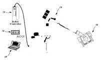
강판 표면의 결함부위 제거를 위해 종래에는 작업자가 육안으로 결함부위를 확인한 다음 각 부위를 일일이 수작업으로 제거하는 방법을 사용하였으나, 수작업의 특성상 작업 능률이 낮을 뿐 아니라 작업부위가 균일하지 못한 문제가 있어 근자 도 7에 개시된 것과 같이 로봇을 이용하는 결함부위 등을 연마하는 방식이 점차 도입되고 있다.Conventionally, in order to remove defects on the surface of a steel sheet, a worker manually identifies defective areas and then manually removes the defects. However, due to the nature of manual work, the work efficiency is low and the work area is not uniform As shown in Fig. 7, a method of grinding a defective portion using a robot is gradually introduced.
이들은 다관절 로봇의 암 단부에 연마기구를 장착한 다음 제어장치에서 신호가 입력되면 해당 부위로 암이 이동하여 입력되는 수치에 해당하는 값만큼 연마기구를 작동시키는 방식인데, 종래 수작업에 비해 작업 능률을 제고시킬 수 있음은 물론 균일한 연마가 가능한 장점이 기대되어 그 활용범위가 점점 확대되고 있는 추세이다.When a signal is inputted from a control device after the grinding device is mounted on the arm end of the articulated robot, the grinding device is operated by a value corresponding to the value of the arm that is moved to the relevant part. And it is expected to be able to uniformly polish it, and the application range thereof is increasing.
하지만, 현재 제안되고 있는 로봇 연마장치들 대부분은 로봇의 암 단부에 단일의 연마기구만을 장착할 수 있는 구조로서 정삭(또는 황삭) 작업이 필요한 경우에는 연마기구를 교체해야 하는 번거로움이 있다. 또한, 대개의 경우 로봇 암의 단부에 장착되는 연마기구의 면이 작업이 필요한 강판의 표면에 긴밀하게 밀착되지 못하는 구성이라는 점에서 이에 대한 개선방안이 필요하다.However, most of the currently proposed robot grinding apparatuses are capable of mounting only a single grinding tool on the end of the arm of the robot, and it is troublesome to replace the grinding tool when finishing (or roughing) work is required. In addition, in most cases, the surface of the polishing apparatus mounted on the end portion of the robot arm can not be closely adhered to the surface of the steel sheet requiring work.
본 발명은 이러한 종래 기술의 문제점을 해결하기 위해 제안된 것으로서, 본 발명의 목적은 별도의 연마기구 교체 없이 연속적인 연마작업이 가능함은 물론 보다 완전한 표면 연마작업이 가능한 로봇 연마장치를 제공함에 있다.It is an object of the present invention to provide a robot polishing apparatus capable of performing a continuous polishing operation without replacing a separate polishing apparatus as well as a more complete surface polishing operation.
본 발명은 이러한 목적을 달성하기 위하여, 다관절 암(3)의 단부에 연마기구(10)가 마련되어 열연강판의 표면을 연마하는 로봇 연마장치로서, 상기 연마기구(10)는, 다관절 암(3)의 단부에 장착되는 압력센서(110); 압력센서(110) 하면에 고정설치되는 진동흡수판(120); 진동흡수판(120) 하면에 결합되는 고정판(131)과, 일정면적으로 가지며 고정판(131)의 하부 일측부위에 위치하되 일측부위가 고정판(131)의 일단부위에 힌지결합되는 제1가동판(132)과, 일정면적을 가지며 고정판(131)의 하부 타측부위에 위치하되 일측부위가 고정판(131)의 타단부위에 힌지결합되는 제2가동판(136)과, 제1가동판(132)의 타측부위에 복수 개가 마련되되 각 하단부위는 제1가동판(132)에 결합되고 각 상단부위는 고정판(131)을 관통하여 삽입되는 제1가이드핀(134)과, 제2가동판(136)의 타측부위에 복수 개가 마련되되 각 하단부위는 제2가동판(136)에 결합되고 각 상단부위는 고정판(131)을 관통하여 삽입되는 제2가이드핀(138)과, 각 제1가이드핀(134)의 외면을 감싸며 장착되어 힌지결합점을 기준으로 제1가동판(132)의 타측부위를 고정판(131)에 대하여 일정간격 이격시키는 제1탄성스프링(135)와, 각 제2가이드핀(138)의 외면을 감싸며 장착되어 힌지결합점을 기준으로 제2가동판(136)의 타측부위를 고정판(131)에 대하여 일정간격 이격시키는 제2탄성스프링(139)이 구비되는 가압판(130); 제1숫돌(146)이 구비되어 제1가동판(132) 하부에 장착되는 제1연마기(140); 제2숫돌(156)이 구비되어 제2가동판(136) 하부에 장착되는 제2연마기(150);로 이루어지는 것을 그 기술적 특징으로 한다.In order to achieve the above object, the present invention provides a robot polishing apparatus provided with a polishing mechanism (10) at an end of a polyarticular arm (3) to polish a surface of a hot rolled steel sheet, wherein the polishing apparatus (10) 3); A
본 발명은 황삭 작업이나 정삭 작업과 같이 서로 다른 연마 작업을 수행할 수 있는 숫돌을 병렬 배치함으로써, 서로 다른 작업을 위해 숫돌의 교체 없이 강판의 표면 연마 작업을 연속하여 또는 선택적으로 수행할 수 있다는 점에서 작업 능률을 현저히 제고시킬 수 있다.The present invention is capable of continuously or selectively polishing the surface of the steel sheet without replacing the grinding wheel for different operations by arranging the grinding wheels capable of performing different grinding operations such as roughing and finishing operations in parallel It is possible to remarkably improve the work efficiency in the work.
또한, 본 발명은 병렬 배치된 각 숫돌이 가동판에 의해 작동되는 탄성스프링에 의해 가압되도록 구성하여 숫돌이 강판의 표면에 긴밀하게 밀착된 상태에서 연마 작업이 이루어지도록 하여 보다 완전하고 균일한 연마 작업이 가능하다.Further, according to the present invention, each grindstone arranged in parallel is pressed by an elastic spring operated by a movable plate, so that the grindstone is brought into close contact with the surface of the steel plate so that a more complete and uniform grinding operation This is possible.
도 1은 본 발명에 따른 로봇 연마장치의 개략적인 전체 구성도.
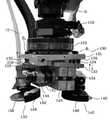
도 2는 본 발명에 따른 로봇 연마장치에 있어 연마기구의 개략적인 측면구성도.
도 3 및 도 4 각각은 본 발명에 따른 로봇 연마장치에 있어 연마기구의 개략적인 사시구성도.
도 5는 본 발명에 따른 로봇 연마장치에 있어 가압판의 개략적인 평면구성도.
도 6은 본 발명에 따른 로봇 연마장치에 있어 가압판의 개략적인 측면구성도.
도 7은 종래 로봇 연마장치의 일 구성도.BRIEF DESCRIPTION OF THE DRAWINGS Fig. 1 is a schematic overall configuration diagram of a robot polishing apparatus according to the present invention; Fig.
BACKGROUND OF THE
Figs. 3 and 4 are schematic perspective configuration views of a polishing apparatus in a robot polishing apparatus according to the present invention; Fig.
5 is a schematic plan view of a platen in a robot polishing apparatus according to the present invention;
6 is a schematic side view of a platen in a robot polishing apparatus according to the present invention;
7 is a block diagram of a conventional robot polishing apparatus.
본 발명에 따른 바람직한 실시예를 첨부된 도면을 참조하여 상세하게 살펴보면 다음과 같은데, 본 발명의 실시예를 상술함에 있어 본 발명의 기술적 특징과 직접적인 관련성이 없거나, 또는 본 발명이 속하는 기술 분야에서 통상의 지식을 가진 자에게 자명한 사항에 대해서는 그 상세한 설명을 생략하기로 한다.DETAILED DESCRIPTION OF THE PREFERRED EMBODIMENTS Preferred embodiments of the present invention will now be described in detail with reference to the accompanying drawings. However, the present invention is not limited to the technical features of the present invention, A detailed description thereof will be omitted.
도 1은 본 발명에 따른 로봇 연마장치의 개략적인 전체 구성도이며, 도 2는 본 발명에 따른 로봇 연마장치에 있어 연마기구의 개략적인 측면구성도이다. 도면에 개시된 것과 같이 본 발명은 로봇 연마장치(1)의 다관절 암(3) 단부에 장착되는 연마기구(10)에 관한 것으로서, 특히 연마기구(10)는 압력센서(110), 진동흡수판(120), 가압판(130), 제1, 2연마기(140, 150)를 포함하여 이루어지는 특징이 있다. 이하 연마기구(10)를 이루는 각 구성을 구체적으로 살펴본다.FIG. 1 is a schematic overall configuration view of a robot polishing apparatus according to the present invention, and FIG. 2 is a schematic side view of a polishing apparatus in a robot polishing apparatus according to the present invention. As shown in the drawings, the present invention relates to a
압력센서(110)는 로봇 연마장치(1)의 다관절 암(3)의 단부에 장착된다. 압력센서(110)는 미도시된 별도의 제어장치와 연결되며, 제1, 2연마기(140, 150) 각각에 가해지는 압력을 감지하며 제어장치에서 입력되는 신호에 따라 제1, 2연마기가 일정한 압력을 유지하도록 하는 수단이다. 이러한 압력센서는 구성은 관련 업계에 널리 알려져 있는바 상세한 설명은 생략한다.The
진동흡수판(120)은 제1, 2연마기(140, 150)를 이용한 연마작업 중에 전달되는 진동을 흡수하는 수단으로 압력센서(110)의 하면에 고정설치된다. 진동흡수판은 일정 두께를 가지는 탄성재질의 합성수지로 이루어질 수 있다.The
가압판(130)은 연마 작업이 이루어지는 동안 제1, 2연마기(140, 150)를 강판의 표면에 밀착시키는 수단으로, 고정판(131), 제1, 2가동판(132, 136), 제1, 2가이드핀(134, 138), 제1, 2탄성스프링(135, 139)을 포함하여 이루어진다. 이를 도 3 내지 도 6 각각을 참조하여 살펴본다.The
고정판(131)은 일정 넓이 및 일정 두께를 가지는 금속판으로서, 진동흡수판(120) 하면에 결합된다. 도 5에서 도면부호 13은 고정판(131)을 진동흡수판(120)에 결합하기 위해 형성되는 체결공이다.The
제1, 2가동판(132, 136) 각각은 일정 면적 및 일정 두께를 가지는 금속판으로서 고정판(131)의 하부에 힌지결합되어 위치하며, 서로 반대 방향으로 힌지 운동할 수 있도록 결합된다. 즉, 제1가동판(132)은 고정판(131)의 하부 일측부위에 위치하되 일측부위가 고정판(131)의 일단부위에 힌지결합되며, 제2가동판(136)은 고정판(131)의 하부 타측부위에 위치하되 일측부위가 고정판(131)의 타단부위에 힌지결합된다. 도면부호 132, 137 각각은 제1, 2힌지핀이다.Each of the first and second
제1가이드핀(134)은 상호 간에 일정간격 이격되어 제1가동판(132)의 타측부위에 위치하는 복수 개로 이루어지되, 각각의 하단부위는 제1가동판(132)에 결합되고 각각의 상단부위는 고정판(131)을 관통하여 삽입된다. 제2가이드핀(138)은 상호 간에 일정간격 이격되어 제2가동판(136)의 타측부위에 위치하는 복수 개로 이루어지되, 각각의 하단부위는 제2가동판(136)에 결합되고 각각의 상단부위는 고정판(131)을 관통하여 삽입된다.The
제1, 2탄성스프링(135, 139) 각각은 제1, 2가이드핀(134, 138) 각각의 외면을 감싸며 장착되어 각 힌지결합점을 기준으로 제1, 2가동판(132, 136)의 각각의 타측부위를 고정판(131)에 대하여 일정간격 이격시킨다. 즉, 제1, 2힌지핀(132, 137) 각각에 의해 일측부위가 고정판(131)의 일단부위 및 타단부위에 힌지결합되어 있는 제1, 2가동판(132, 136) 각각의 타측부위는 제1, 2탄성스프링(135, 139)의 탄성력에 의해 고정판(131)으로부터 강제적으로 일정 간격 이격된다.Each of the first and second
도면부호 B1, B2 각각은 고정판(131)에 힌지결합된 제1, 2가동판(132, 136) 각각의 간격(힌지 이동가능한 간격)을 조절하기 위한 볼트로서, 헤드가 마련되는 각각의 상단부위는 고정판(131)에 관통 삽입되고 각각의 하측부위는 제1, 2가동판(132, 136) 각각에 치합된다.Reference numerals B1 and B2 denote bolts for adjusting the spacing of the first and second
제1연마기(140)는 제1가동판(132) 하부에 장착되며, 제1숫돌(146)이 구비된다. 제1숫돌(146)은 연삭용 숫돌로 이루어질 수 있다. 도면부호 142, 144 각각은 제1고정편 및 제1공기주입단이고, 도면부호 148은 제1안전커버이다. 제2연마기(150)는 제2가동판(136) 하부에 장착되며, 제2숫돌(156)이 구비된다. 제2숫돌(156)은 황삭용 숫돌로 이루어질 수 있다. 도면부호 152, 154 각각은 제2고정편 및 제2공기주입단이고, 도면부호 158은 제2안전커버이다.The
이러한 구성으로 이루어지는 본 발명의 개략적인 작동구성을 전술한 설명부분을 참조하여 살펴본다. 설명의 편의를 위해 제1, 2숫돌 각각은 정삭 숫돌 및 황삭 숫돌이 장착된 경우를 상정한다.The schematic operation configuration of the present invention having such a configuration will be described with reference to the above description. For convenience of explanation, it is assumed that the first and second grindstones are equipped with a grinding wheel and a grinding wheel, respectively.
강판이 일정 길이로 펼쳐진 상태에서 작업자 또는 카메라가 강판의 상태를 점검하면서 강판의 표면에 존재하는 결함부위를 체크한다. 결함부위가 확인되면 제어장치에서 로봇 연마장치(1)로 신호가 입력되고, 이에 따라 로봇 연마장치(1)는 강판의 결함부위로 이동한다. 로봇 연마장치의 이동은 별도의 가이드모터에 의해 이루어질 수 있다.When the steel plate is unfolded to a certain length, the operator or the camera checks the state of the steel plate and checks the defective portion existing on the surface of the steel plate. When the defective portion is confirmed, a signal is inputted from the control device to the
로봇 연마장치(1)가 결함부위 근처로 이동하면, 제어장치에서 별도의 신호가 입력되어 다관절 암(3)이 작동하여 연마기구(10)를 결함부위로 접근시킨다. 이때, 결함부위의 상태에 따라 정삭 작업을 위한 제1숫돌(146) 또는 황삭 작업을 위한 제2숫돌(156) 중의 어느 숫돌을 사용할지 여부를 결정한다. 황삭 작업이 선행될 필요가 있으면 제2숫돌(156)을 강판의 표면에 밀착시킨다.When the
이때, 제어신호의 입력에 따라 다관절 암(3)이 제2숫돌(156)을 하방으로 가압하면, 가해지는 힘에 의해 제2가동판(136)이 제2탄성스프링(139)을 압축하면서 제2힌지핀(137)을 기점으로 상방으로 힌지 이동한다(도 3, 도 4, 도 6 각각에서 실선). 이에 따라, 제2숫돌(156)은 강판의 표면에 긴밀하게 밀착되고, 뒤이어 고압의 공기가 주입되면서 제2숫돌(156)에 의한 일정 시간 동안 황삭 작업이 수행된다.At this time, when the
황삭 작업이 완료되면, 다관절 암(3)이 상방으로 일정 거리 이동하면 제2숫돌(156)이 강판의 표면으로부터 분리된다. 다관절 암(3)이 제2숫돌(156)을 가압하는 힘이 해제됨에 따라, 제2가동판(136)은 제2탄성스프링(139)의 복원력에 의해 제2힌지핀(137)을 기점으로 하방으로 힌지 이동하며 원위치로 복귀한다(도 3, 도 4, 도 6 각각에서 점선).When the roughing operation is completed, the
이후, 이어지는 정삭 작업은 전술한 설명과 동일한 과정을 거쳐 제1숫돌(146)을 강판에 밀착시킨 상태에서 이루어지며, 제1힌지핀(132)을 기점으로 한 제1가동판(132)과 제1탄성스프링(135) 상호 간의 작동구성은 황삭 작업에서의 작동구성과 대동소이하다(실선은 가압/점선은 복원). 각 작업에 있어 압력센서(110)는 다관절 암(3)이 제1, 2숫돌을 일정한 힘으로 가압하도록 기능한다.Thereafter, the subsequent finishing operation is performed in a state in which the
상기에서는 본 발명의 바람직한 실시예들에 한정하여 설명하였으나 이는 단지 예시일 뿐이며, 본 발명은 이에 한정되지 않고 여러 다양한 방법으로 변경되어 실시될 수 있으며, 나아가 개시된 기술적 사상에 기초하여 별도의 기술적 특징이 부가되어 실시될 수 있음은 자명하다 할 것이다.While the present invention has been particularly shown and described with reference to exemplary embodiments thereof, it is to be understood that the invention is not limited to the disclosed embodiments, but, on the contrary, is intended to cover various modifications and equivalent arrangements included within the spirit and scope of the appended claims. It will be apparent that the present invention can be practiced with added features.
1 : 로봇 연마장치 3 : 다관절 암
10 : 연마기구 110 : 압력센서
120 : 진동흡수판 130 : 가압판
140 : 제1연마기 150 : 제2연마기1: Robot polishing device 3: Multi-jointed arm
10: polishing device 110: pressure sensor
120: vibration absorption plate 130: pressure plate
140: first polishing machine 150: second polishing machine
Claims (1)
Translated fromKorean상기 연마기구(10)는,
다관절 암(3)의 단부에 장착되는 압력센서(110);
압력센서(110) 하면에 고정설치되는 진동흡수판(120);
진동흡수판(120) 하면에 결합되는 고정판(131)과, 일정면적으로 가지며 고정판(131)의 하부 일측부위에 위치하되 일측부위가 고정판(131)의 일단부위에 힌지결합되는 제1가동판(132)과, 일정면적을 가지며 고정판(131)의 하부 타측부위에 위치하되 일측부위가 고정판(131)의 타단부위에 힌지결합되는 제2가동판(136)과, 제1가동판(132)의 타측부위에 복수 개가 마련되되 각 하단부위는 제1가동판(132)에 결합되고 각 상단부위는 고정판(131)을 관통하여 삽입되는 제1가이드핀(134)과, 제2가동판(136)의 타측부위에 복수 개가 마련되되 각 하단부위는 제2가동판(136)에 결합되고 각 상단부위는 고정판(131)을 관통하여 삽입되는 제2가이드핀(138)과, 각 제1가이드핀(134)의 외면을 감싸며 장착되어 힌지결합점을 기준으로 제1가동판(132)의 타측부위를 고정판(131)에 대하여 일정간격 이격시키는 제1탄성스프링(135)와, 각 제2가이드핀(138)의 외면을 감싸며 장착되어 힌지결합점을 기준으로 제2가동판(136)의 타측부위를 고정판(131)에 대하여 일정간격 이격시키는 제2탄성스프링(139)이 구비되는 가압판(130);
제1숫돌(146)이 구비되어 제1가동판(132) 하부에 장착되는 제1연마기(140);
제2숫돌(156)이 구비되어 제2가동판(136) 하부에 장착되는 제2연마기(150);로
이루어지는 것을 특징으로 하는 열연강판의 로봇 연마장치.
A robot polishing apparatus for polishing a surface of a hot-rolled steel plate provided with a polishing mechanism (10) at an end of a multi-jointed arm (3)
The polishing apparatus (10)
A pressure sensor 110 mounted on an end of the articulated arm 3;
A vibration absorbing plate 120 fixedly installed on a lower surface of the pressure sensor 110;
A first movable plate 131 having a predetermined area and being located at one side of a lower portion of the fixed plate 131 and having one side hinged to one end of the fixed plate 131, A second movable plate 136 having a predetermined area and being hinged to the other end of the fixed plate 131 at one side of the fixed plate 131, A first guide pin 134 inserted into the first movable plate 132 and inserted into the first fixed plate 131 through the first movable plate 132 and a second movable plate 136 inserted through the second fixed plate 131, A second guide pin 138 which is coupled to the second movable plate 136 and has an upper end inserted through the fixing plate 131, 134, and the other side of the first movable plate 132 is fixed with respect to the fixing plate 131 with respect to the hinge connection point A first elastic spring 135 which separates the second movable plate 136 from the fixed plate 131 by a predetermined distance from the fixed plate 131 with the other side of the second movable plate 136 mounted on the outer surface of each second guide pin 138, A pressure plate 130 provided with a second elastic spring 139 for separating the pressure plate 130;
A first polishing machine 140 having a first grindstone 146 mounted on a lower portion of the first movable plate 132;
A second polishing machine 150 having a second grindstone 156 mounted on a lower portion of the second movable plate 136;
Wherein said robot is a robot.
Priority Applications (1)
| Application Number | Priority Date | Filing Date | Title |
|---|---|---|---|
| KR1020160060784AKR101824225B1 (en) | 2016-05-18 | 2016-05-18 | Surface grinding robot for hot rolled steel sheet |
Applications Claiming Priority (1)
| Application Number | Priority Date | Filing Date | Title |
|---|---|---|---|
| KR1020160060784AKR101824225B1 (en) | 2016-05-18 | 2016-05-18 | Surface grinding robot for hot rolled steel sheet |
Publications (2)
| Publication Number | Publication Date |
|---|---|
| KR20170130131A KR20170130131A (en) | 2017-11-28 |
| KR101824225B1true KR101824225B1 (en) | 2018-01-31 |
Family
ID=60811340
Family Applications (1)
| Application Number | Title | Priority Date | Filing Date |
|---|---|---|---|
| KR1020160060784AActiveKR101824225B1 (en) | 2016-05-18 | 2016-05-18 | Surface grinding robot for hot rolled steel sheet |
Country Status (1)
| Country | Link |
|---|---|
| KR (1) | KR101824225B1 (en) |
Cited By (3)
| Publication number | Priority date | Publication date | Assignee | Title |
|---|---|---|---|---|
| WO2020111810A1 (en)* | 2018-11-29 | 2020-06-04 | 주식회사 포스코 | An apparatus for controlling a cleaning robot and a control method for the same |
| KR20200064473A (en) | 2018-11-29 | 2020-06-08 | 주식회사 포스코 | Apparatus for grinding |
| KR20250102708A (en) | 2023-12-28 | 2025-07-07 | (주)정산 | The apparatus for automatically grinding the propeller of the ship |
Families Citing this family (5)
| Publication number | Priority date | Publication date | Assignee | Title |
|---|---|---|---|---|
| CN108943021A (en)* | 2018-07-30 | 2018-12-07 | 广东宏穗晶科技服务有限公司 | A kind of open air exploration is with photography machine people |
| CN108705546A (en)* | 2018-08-03 | 2018-10-26 | 苏州夏木自动化科技有限公司 | A kind of accurately robot automatic sander |
| KR102369712B1 (en)* | 2020-02-04 | 2022-03-08 | 주식회사 알투람 | Surface grinding device for hot rolled steel sheet |
| CN113618576B (en)* | 2021-07-23 | 2022-08-05 | 东风汽车底盘系统有限公司 | Automatic guide arm polishing system and automatic polishing method |
| CN114227452A (en)* | 2021-12-08 | 2022-03-25 | 东莞长盈精密技术有限公司 | Polishing device, polishing equipment and polishing method |
Citations (1)
| Publication number | Priority date | Publication date | Assignee | Title |
|---|---|---|---|---|
| KR101620785B1 (en)* | 2015-02-25 | 2016-05-13 | 울산대학교 산학협력단 | Apparatus for processing surface |
- 2016
- 2016-05-18KRKR1020160060784Apatent/KR101824225B1/enactiveActive
Patent Citations (1)
| Publication number | Priority date | Publication date | Assignee | Title |
|---|---|---|---|---|
| KR101620785B1 (en)* | 2015-02-25 | 2016-05-13 | 울산대학교 산학협력단 | Apparatus for processing surface |
Cited By (5)
| Publication number | Priority date | Publication date | Assignee | Title |
|---|---|---|---|---|
| WO2020111810A1 (en)* | 2018-11-29 | 2020-06-04 | 주식회사 포스코 | An apparatus for controlling a cleaning robot and a control method for the same |
| KR20200064473A (en) | 2018-11-29 | 2020-06-08 | 주식회사 포스코 | Apparatus for grinding |
| KR20200065152A (en)* | 2018-11-29 | 2020-06-09 | 주식회사 포스코 | An apparatus for controlling a cleaning robot and a control method for the same |
| KR102178742B1 (en)* | 2018-11-29 | 2020-11-16 | 주식회사 포스코 | An apparatus for controlling a cleaning robot and a control method for the same |
| KR20250102708A (en) | 2023-12-28 | 2025-07-07 | (주)정산 | The apparatus for automatically grinding the propeller of the ship |
Also Published As
| Publication number | Publication date |
|---|---|
| KR20170130131A (en) | 2017-11-28 |
Similar Documents
| Publication | Publication Date | Title |
|---|---|---|
| KR101824225B1 (en) | Surface grinding robot for hot rolled steel sheet | |
| TWI490061B (en) | Verfahren und vorrichtung zum schleifen eines stranggussprodukts | |
| CN106863053B (en) | A kind of edge grinding method and grinding equipment of thin plate and strip steel | |
| CN203185091U (en) | Novel face grinding machine | |
| CN109414748A (en) | Hemming processing apparatus and hemming processing method | |
| CN104551941A (en) | Two-sided belt sander | |
| JP5915816B2 (en) | Roller hemming processing apparatus and roller hemming processing method | |
| WO2016152968A1 (en) | Processing device | |
| JP6405994B2 (en) | Roll hemming machine | |
| KR940001129B1 (en) | Grinding Device Of Belt Material | |
| JPH0890397A (en) | Grinding stone mounting structure for detecting minute defects in steel sheet | |
| KR20100024650A (en) | Automatic grinding apparatus for spot welding area by using spot welding robot and the method | |
| KR20140116735A (en) | Grinding machine of door frame for vehicle | |
| TWI680107B (en) | Glass plate bend-breaking machine | |
| KR101386887B1 (en) | Simultaneous clamping and step-driven processing step molding machine molding machine equipped with roof sheets | |
| KR20170065796A (en) | A Forging Manipulator | |
| CN204935316U (en) | A kind of vehicle brake sheet lapping device | |
| KR101306938B1 (en) | Metal plate-working tool set for fender of automobile | |
| KR102369712B1 (en) | Surface grinding device for hot rolled steel sheet | |
| JP6405961B2 (en) | Roll hemming method and roll hemming apparatus | |
| JPH06246354A (en) | Bending method for damping steel plate | |
| JPH0773821B2 (en) | Relative angle adjustable belt sander | |
| CN203484549U (en) | Self-adjusting positioning device of raw steel plate | |
| US1828212A (en) | Grinding apparatus | |
| CN220463488U (en) | Intelligent grinding disc device |
Legal Events
| Date | Code | Title | Description |
|---|---|---|---|
| A201 | Request for examination | ||
| PA0109 | Patent application | Patent event code:PA01091R01D Comment text:Patent Application Patent event date:20160518 | |
| PA0201 | Request for examination | ||
| PG1501 | Laying open of application | ||
| PE0701 | Decision of registration | Patent event code:PE07011S01D Comment text:Decision to Grant Registration Patent event date:20180115 | |
| GRNT | Written decision to grant | ||
| PR0701 | Registration of establishment | Comment text:Registration of Establishment Patent event date:20180125 Patent event code:PR07011E01D | |
| PR1002 | Payment of registration fee | Payment date:20180125 End annual number:3 Start annual number:1 | |
| PG1601 | Publication of registration | ||
| PR1001 | Payment of annual fee | Payment date:20201110 Start annual number:4 End annual number:4 | |
| PR1001 | Payment of annual fee | Payment date:20211130 Start annual number:5 End annual number:5 | |
| PR1001 | Payment of annual fee | Payment date:20221130 Start annual number:6 End annual number:6 | |
| PR1001 | Payment of annual fee | Payment date:20231130 Start annual number:7 End annual number:7 |