KR101823855B1 - Multiple radiation inspection of ophthalmic lenses - Google Patents
Multiple radiation inspection of ophthalmic lensesDownload PDFInfo
- Publication number
- KR101823855B1 KR101823855B1KR1020137034891AKR20137034891AKR101823855B1KR 101823855 B1KR101823855 B1KR 101823855B1KR 1020137034891 AKR1020137034891 AKR 1020137034891AKR 20137034891 AKR20137034891 AKR 20137034891AKR 101823855 B1KR101823855 B1KR 101823855B1
- Authority
- KR
- South Korea
- Prior art keywords
- radiation
- image
- ophthalmic lens
- irradiated
- storage area
- Prior art date
- Legal status (The legal status is an assumption and is not a legal conclusion. Google has not performed a legal analysis and makes no representation as to the accuracy of the status listed.)
- Active
Links
- 230000005855radiationEffects0.000titleclaimsabstractdescription40
- 238000007689inspectionMethods0.000titledescription3
- 238000000034methodMethods0.000claimsabstractdescription26
- 238000012432intermediate storageMethods0.000claimsdescription11
- 230000007547defectEffects0.000claimsdescription6
- 239000000017hydrogelSubstances0.000claimsdescription6
- 229920001296polysiloxanePolymers0.000claimsdescription6
- 230000001678irradiating effectEffects0.000claimsdescription5
- 238000004519manufacturing processMethods0.000claimsdescription5
- 238000004806packaging method and processMethods0.000claimsdescription3
- 238000003860storageMethods0.000claims1
- 230000003287optical effectEffects0.000abstractdescription4
- 239000000243solutionSubstances0.000description6
- 238000009472formulationMethods0.000description3
- 238000010191image analysisMethods0.000description3
- 239000000203mixtureSubstances0.000description3
- 239000007864aqueous solutionSubstances0.000description2
- 238000011109contaminationMethods0.000description2
- 239000008367deionised waterSubstances0.000description2
- 229910021641deionized waterInorganic materials0.000description2
- 239000000463materialSubstances0.000description2
- XLYOFNOQVPJJNP-UHFFFAOYSA-NwaterChemical compoundOXLYOFNOQVPJJNP-UHFFFAOYSA-N0.000description2
- FAPWRFPIFSIZLT-UHFFFAOYSA-MSodium chlorideChemical compound[Na+].[Cl-]FAPWRFPIFSIZLT-UHFFFAOYSA-M0.000description1
- 239000002152aqueous-organic solutionSubstances0.000description1
- 238000012512characterization methodMethods0.000description1
- 238000003384imaging methodMethods0.000description1
- 239000000178monomerSubstances0.000description1
- 229910052710siliconInorganic materials0.000description1
- 239000010703siliconSubstances0.000description1
- 239000011780sodium chlorideSubstances0.000description1
- 230000003595spectral effectEffects0.000description1
Images

Classifications
- G—PHYSICS
- G01—MEASURING; TESTING
- G01M—TESTING STATIC OR DYNAMIC BALANCE OF MACHINES OR STRUCTURES; TESTING OF STRUCTURES OR APPARATUS, NOT OTHERWISE PROVIDED FOR
- G01M11/00—Testing of optical apparatus; Testing structures by optical methods not otherwise provided for
- G01M11/02—Testing optical properties
- G01M11/0242—Testing optical properties by measuring geometrical properties or aberrations
- G01M11/0257—Testing optical properties by measuring geometrical properties or aberrations by analyzing the image formed by the object to be tested
- G—PHYSICS
- G01—MEASURING; TESTING
- G01N—INVESTIGATING OR ANALYSING MATERIALS BY DETERMINING THEIR CHEMICAL OR PHYSICAL PROPERTIES
- G01N21/00—Investigating or analysing materials by the use of optical means, i.e. using sub-millimetre waves, infrared, visible or ultraviolet light
- G01N21/84—Systems specially adapted for particular applications
- G01N21/88—Investigating the presence of flaws or contamination
- G01N21/8806—Specially adapted optical and illumination features
- G01N2021/8845—Multiple wavelengths of illumination or detection
- G—PHYSICS
- G01—MEASURING; TESTING
- G01N—INVESTIGATING OR ANALYSING MATERIALS BY DETERMINING THEIR CHEMICAL OR PHYSICAL PROPERTIES
- G01N21/00—Investigating or analysing materials by the use of optical means, i.e. using sub-millimetre waves, infrared, visible or ultraviolet light
- G01N21/84—Systems specially adapted for particular applications
- G01N21/88—Investigating the presence of flaws or contamination
- G01N21/95—Investigating the presence of flaws or contamination characterised by the material or shape of the object to be examined
- G01N21/958—Inspecting transparent materials or objects, e.g. windscreens
- G01N2021/9583—Lenses
Landscapes
- Physics & Mathematics (AREA)
- Analytical Chemistry (AREA)
- General Physics & Mathematics (AREA)
- Chemical & Material Sciences (AREA)
- Immunology (AREA)
- Biochemistry (AREA)
- General Health & Medical Sciences (AREA)
- Life Sciences & Earth Sciences (AREA)
- Health & Medical Sciences (AREA)
- Pathology (AREA)
- Geometry (AREA)
- Investigating Materials By The Use Of Optical Means Adapted For Particular Applications (AREA)
- Testing Of Optical Devices Or Fibers (AREA)
- Eyeglasses (AREA)
- Photometry And Measurement Of Optical Pulse Characteristics (AREA)
- Eye Examination Apparatus (AREA)
- Investigating Or Analysing Biological Materials (AREA)
Abstract
Translated fromKoreanDescription
Translated fromKorean본 발명은 안과용 렌즈, 특히 실리콘 하이드로겔 콘택트렌즈를 하나 이상의 파장들의 방사선을 사용하여 검사하는 것에 관한 것이다.The present invention relates to the examination of ophthalmic lenses, in particular silicone hydrogel contact lenses, using radiation of one or more wavelengths.
소프트 콘택트렌즈와 같은 안과용 렌즈는 수반되는 패키징 용액과 함께 일회용 패키지(통상, 블리스터 패키지(blister package)로 지칭됨)로 소비자에게 전달된다. 전형적으로, 그러한 안과용 렌즈는 사람이 최소한으로 개입하여 제조 라인에서 형성, 검사 및 패키징된다.Ophthalmic lenses, such as soft contact lenses, are delivered to the consumer in a disposable package (commonly referred to as a blister package) with the accompanying packaging solution. Typically, such ophthalmic lenses are formed, inspected and packaged in a manufacturing line with minimal human intervention.
전술된 검사 방법에 의해서도, 안과용 렌즈 내의 구멍과 같은 결함과 용액 내에서 발견되는 기포를 구분하는 것은 종종 어렵다. 그러한 구별은 중요한데, 그 이유는 결함의 잘못된 특성화로 인해 렌즈가 검사에 통과하지 못하면, 만족스러운 제품이 오류로 폐기될 수 있으며 실제로 존재하지 않는 렌즈에 대한 결함의 원인을 밝히기 위해 공정이 불필요하게 수정될 수 있기 때문이다. 따라서, 안과용 렌즈 내의 결함과 패키지 내의 기포를 구분할 수 있는 것이 중요하다. 이러한 필요성이 하기의 발명에 의해 충족된다.With the above-described inspection method, it is often difficult to distinguish defects such as holes in an ophthalmic lens from bubbles found in a solution. Such a distinction is important because if the lens fails to pass the inspection due to erroneous characterization of the defect then a satisfactory product may be discarded as an error and the process may be unnecessarily modified to reveal the cause of the defect It can be. Therefore, it is important to be able to distinguish defects in the ophthalmic lens from bubbles in the package. This necessity is satisfied by the following invention.
<도 1>
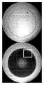
도 1은 구멍을 보여주는, 광의 상이한 파장들에 의한 안과용 렌즈의 이미지들.
<도 2>
도 2는 기포를 보여주는, 광의 상이한 파장들에 의한 안과용 렌즈의 이미지들.≪ 1 >
Figure 1 shows images of an ophthalmic lens by different wavelengths of light, showing holes.
2,
2 shows images of an ophthalmic lens by different wavelengths of light, showing bubbles.
본 발명은 제조 라인을 통해 이동하는, 패키징 용액과 함께 용기 내에 내장된 실리콘 하이드로겔 안과용 렌즈를 검사하는 방법으로서,The present invention provides a method of inspecting a silicone hydrogel ophthalmic lens embedded in a container with a packaging solution,
(a) 가시, 자외, 또는 적외 방사선으로 이루어지는 군의 하나 이상의 구성원을 포함한 방사선으로 안과용 렌즈를 조사하여 제1 이미지를 생성하는 단계;(a) irradiating an ophthalmic lens with radiation comprising at least one member of the group consisting of visible, ultraviolet, or infrared radiation to produce a first image;
(b) 제1 이미지를 중간 저장 영역으로 전달하는 단계;(b) transferring a first image to an intermediate storage area;
(c) 가시, 자외, 및 적외 방사선으로 이루어지는 군의 하나 이상의 구성원을 포함한 방사선으로 안과용 렌즈를 조사하여 제2 이미지를 생성하는 단계로서, 단계 (c)의 조사 방사선이 단계 (a)의 조사 방사선과는 상이하고, 상기 단계 (c)의 조사가 단계 (a)의 조사 후에 실질적으로 짧은 기간 내에 수행되는, 상기 안과용 렌즈를 조사하여 제2 이미지를 생성하는 단계;(c) irradiating the ophthalmic lens with radiation comprising at least one member of the group consisting of visible, ultraviolet, and infrared radiation to produce a second image, wherein the radiation of step (c) Irradiating the ophthalmic lens to produce a second image, wherein the radiation is different and the irradiation of step (c) is performed within a substantially short period of time after irradiation of step (a);
(d) 제1 이미지를 중간 저장 영역으로부터 이미지 캡쳐링 장치(image capturing device)로 전달하는 단계;(d) transferring the first image from the intermediate storage area to an image capturing device;
(e) 제2 이미지를 중간 저장 영역으로 전달하는 단계;(e) transferring the second image to the intermediate storage area;
(f) 제2 이미지를 이미지 캡쳐링 장치로 전달하는 단계;(f) passing a second image to an image capturing device;
(g) 안과용 렌즈가 결함을 포함하는지를 결정하기 위해 이미지 캡쳐링 장치로부터 관찰될 때 제1 이미지와 제2 이미지를 비교하는 단계를 포함하는, 방법이 제공된다.(g) comparing the first image and the second image when viewed from the image capturing device to determine if the ophthalmic lens comprises a defect.
본 명세서에 사용되는 바와 같이, 용어 "실리콘 하이드로겔 안과용 렌즈"는 실리콘을 함유하는 단량체, 거대단량체(macromer) 또는 예비중합체(prepolymer)로 제조된 소프트 콘택트렌즈를 말한다. 그러한 안과용 렌즈의 예들은 하기의 일반 제형들, 즉 발라필콘, 로트라필콘, 갈리필콘, 엔필콘, 콤필콘, 세노필콘, 및 나라필콘으로 제조되는 렌즈들을 포함하지만 이로 한정되지 않는다. 바람직한 규소 하이드로겔 안과용 렌즈는 하기의 제형들, 즉 콤필콘, 갈리필콘, 세노필콘 및 나라필콘으로부터 제조된다. 특히 바람직한 안과용 렌즈는 하기의 제형들, 즉 갈리필콘, 세노필콘, 및 나라필콘으로부터 제조된다.As used herein, the term "silicone hydrogel ophthalmic lens" refers to soft contact lenses made of monomers, macromers or prepolymers containing silicon. Examples of such ophthalmic lenses include, but are not limited to, the following general formulations: Balacilcon, Lotrafilcon, Galifilcon, Enfilcon, Comfilcon, Senofilcon, and lenses made from Nalil. Preferred silicone hydrogel ophthalmic lenses are made from the following formulations: Comfilcon, Galipilcon, Senofilcon, and Nalilcon. Particularly preferred ophthalmic lenses are made from the following formulations: Galfilcon, Senofilcon, and Nalilcon.
본 명세서에 사용되는 바와 같이, 용어 "용기"는 제조 공정 동안 또는 그 이후에 안과용 렌즈와 용액을 내장하기 위해 사용되는 임의의 리셉터클(receptacle)을 의미한다. 용기의 예들은 트레이(tray), 컵, 렌즈 주형(mold), 블리스터 패키지 보울(blister package bowl) 등을 포함하지만 이로 한정되지 않는다. 바람직한 용기는 트레이 및 블리스터 패키지 보울이다. 제조 공정의 상이한 시점들에서, 안과용 렌즈는 다수의 상이한 수용액들 및 유기 용액들과 접촉할 수 있다. 이 방법을 위한 바람직한 용액들은 탈이온수 및 식염수와 같은 수용액들이다. 바람직한 용액은 탈이온수이다.As used herein, the term "container" refers to any receptacle used to contain an ophthalmic lens and solution during or after the manufacturing process. Examples of containers include, but are not limited to, trays, cups, lens molds, blister package bowls, and the like. Preferred containers are trays and blister package bowls. At different points in the manufacturing process, the ophthalmic lens can contact a number of different aqueous solutions and organic solutions. Preferred solutions for this process are aqueous solutions such as deionized water and saline. A preferred solution is deionized water.
안과용 렌즈는 안과용 렌즈 제조 라인의 상이한 스테이션들을 통해 이동됨에 따라 검사된다. 렌즈는 전형적으로 약 1 내지 약 200 ㎜/sec, 바람직하게는 약 70 내지 약 120 ㎜/sec의 속도로 이동한다.The ophthalmic lens is inspected as it moves through different stations of the ophthalmic lens manufacturing line. The lens typically travels at a speed of from about 1 to about 200 mm / sec, preferably from about 70 to about 120 mm / sec.
이 방법에서, 렌즈는 먼저 가시, 자외 또는 적외 방사선으로 이루어진 군의 하나 이상의 구성원들을 포함하는 방사선으로 조사된다. 가시 방사선은 약 390 ㎚ 내지 약 700 ㎚의 파장을 가지고, 자외 방사선은 약 10 ㎚ 내지 약 390 ㎚의 파장을 가지며, 적외 방사선은 약 700 ㎚ 내지 약 3000 ㎚의 파장을 갖는다. 안과용 렌즈가 가시 범위의 방사선, 바람직하게는 약 440 ㎚ 내지 약 500 ㎚, 더 바람직하게는 약 440 ㎚ 내지 약 475 ㎚의 파장을 갖는 방사선으로 단계 (a)에서 조사되는 것이 바람직하다. 안과용 렌즈가 약 300 ㎚ 내지 약 390 ㎚의 파장, 더 바람직하게는 약 370 ㎚ 내지 약 380 ㎚의 파장을 갖는 자외 범위 내의 방사선으로 단계 (b)에서 조사되는 것이 바람직하다.In this method, the lens is first irradiated with radiation comprising at least one member of the group consisting of visible, ultraviolet or infrared radiation. The visible radiation has a wavelength of about 390 nm to about 700 nm, the ultraviolet radiation has a wavelength of about 10 nm to about 390 nm, and the infrared radiation has a wavelength of about 700 nm to about 3000 nm. It is preferred that the ophthalmic lens is irradiated in step (a) with radiation having a visible range, preferably with a wavelength of from about 440 nm to about 500 nm, more preferably from about 440 nm to about 475 nm. It is preferred that the ophthalmic lens is irradiated in step (b) with radiation in the ultraviolet range having a wavelength of from about 300 nm to about 390 nm, more preferably from about 370 nm to about 380 nm.
게다가, 단계 (a) 또는 단계(b)에서의 방사선은 자외, 가시 및 적외 방사선과 같은 둘 이상의 유형의 방사선의 조합을 포함할 수 있다. 그러한 각각의 유형의 방사선의 비율을 결정하는 기술은, 본 명세서에 전체적으로 참고로 포함된 미국 특허 제6,882,411호에 개시되어 있다. 단계 (a)가 가시 및 자외 방사선을 포함하는 것이 바람직하다.In addition, the radiation in step (a) or step (b) may comprise a combination of two or more types of radiation, such as ultraviolet, visible and infrared radiation. Techniques for determining the proportion of each such type of radiation are disclosed in U.S. Patent No. 6,882,411, which is incorporated herein by reference in its entirety. It is preferred that step (a) comprises visible and ultraviolet radiation.
방사선은 상이한 파장들을 공급하는 2개의 방사선 공급원들에 의해 또는 복수의 파장들의 광을 발생시키는 단일 공급원에 의해 공급될 수 있다. 그러한 방사선 공급원은 연속적인 방사선, 또는 펄스형 방사선을 제공하는데, 여기서 펄스들 사이의 간격은 이미지 생성 타이밍에 의해 조정된다.The radiation may be supplied by two radiation sources supplying different wavelengths or by a single source generating light of a plurality of wavelengths. Such a source of radiation provides continuous radiation, or pulsed radiation, wherein the spacing between pulses is adjusted by the image generation timing.
본 명세서에 사용되는 바와 같은 "중간 저장 영역"은 CCD 칩의 인터라인 전송 아키텍처(interline transfer architecture) 내에서 발견되는 인터라인 시프트 레지스터(interline shift register)를 의미한다. 그러한 중간 저장 영역은 실질적으로 짧은 기간에 2개의 연속적인 이미지들이 캡쳐되게 한다. 중간 저장 영역은 카메라 내부에 위치된다. 중간 저장 영역에 더하여, 본 발명의 방법들에 사용되는 바람직한 카메라는 상이한 스펙트럼 대역들의 방사선을 사용하여 이미지들을 캡쳐하는 것에 의해 야기되는 초점 이동을 최소화하기 위한 특별한 광학계를 포함한다. 본 발명에 사용될 수 있는 카메라는 달사(Dalsa) 4M15 판테라(Pantera), RMV-4021 일루니스(Illunis)와 같은 카메라를 포함하지만 이로 한정되지 않는다. 바람직한 카메라는 이미지 내에 나타나는 허위 아티팩트(false artifact)를 야기할 수 있는 센서의 오염을 최소화하도록 카메라 하우징 내에 밀봉되는 센서들을 갖는다. 이미지화 광학계 설계는 또한 카메라 렌즈 하우징 내의 오염이 이미지에서 허위 아티팩트로 나타나는 것을 방지하기 위해 렌즈 요소 표면에 근접해 있는 카메라 렌즈의 광학 체인 내에 중간 이미지 평면들을 생성하는 것을 피한다. 본 발명의 방법에 사용되는 바람직한 카메라는 약 14 ㎜ 내지 약 22 ㎜, 더 바람직하게는 약 17 ㎜의 시야를 갖는다.An "intermediate storage area" as used herein refers to an interline shift register found within an interline transfer architecture of a CCD chip. Such an intermediate storage area allows two successive images to be captured in a substantially short period of time. The intermediate storage area is located inside the camera. In addition to the intermediate storage area, the preferred camera used in the methods of the present invention includes a special optical system for minimizing focus shift caused by capturing images using radiation of different spectral bands. The cameras that may be used in the present invention include, but are not limited to, cameras such as Dalsa 4M15 Pantera, RMV-4021 Illunis. A preferred camera has sensors that are sealed in the camera housing to minimize contamination of the sensor, which can result in false artifacts appearing in the image. The imaging optical system design also avoids creating intermediate image planes within the optical chain of the camera lens that are close to the lens element surface to prevent contamination within the camera lens housing from appearing as false artifacts in the image. A preferred camera used in the method of the present invention has a field of view of about 14 mm to about 22 mm, more preferably about 17 mm.
본 명세서에 사용되는 바와 같이, "실질적으로 짧은 기간"은 단계 (a)의 조사 및 이미지 캡쳐와 단계 (c)의 조사 및 이미지 캡쳐 사이의 시간이다. 이러한 실질적으로 짧은 기간은 바람직하게는 1 마이크로초 내지 500 마이크로초, 더 바람직하게는 약 75 마이크로초 내지 약 200 마이크로초이다. 이러한 기간은 렌즈가 카메라의 시야를 지나 이동하기 전에 카메라가 제1 이미지와 제2 이미지 둘 모두에서 안과용 렌즈의 전체 이미지를 캡쳐하게 한다.As used herein, "substantially short duration" is the time between the examination of step (a) and the image capture and the examination of step (c) and image capture. This substantially short period is preferably from 1 microsecond to 500 microseconds, more preferably from about 75 microseconds to about 200 microseconds. This period allows the camera to capture the entire image of the ophthalmic lens in both the first image and the second image before the lens moves past the field of view of the camera.
본 명세서에 사용되는 바와 같이, "이미지 분석 장치"는 이미지를 저장하고 선택적으로 후속적으로 조작할 수 있는 임의의 기기를 의미한다. 그러한 이미지 분석 장치의 예들은 관련 소프트웨어를 갖는 컴퓨터, GigE와 같은 카메라, IEEE 1394 카메라, 및 USB를 통해 컴퓨터에 연결되는 다른 카메라들을 포함하지만 이로 한정되지 않는다. 바람직한 이미지 분석 장치는 저장된 이미지를 분석하기 위한 다양한 알고리즘과 프레임 그래버(frame grabber)를 포함하는 컴퓨터이다. 본 발명의 일 실시예에서, 이미지 분석 장치의 소프트웨어는 이미지들을 비교하기 전에 각각의 이미지를 독립적으로 분석하는데, 이는 이미지들을 분석하는 바람직한 방법이다. 다른 실시예에서, 소프트웨어는 둘 모두의 이미지들을 조합하고 이들을 동시에 분석한다.As used herein, an "image analyzing device" means any device capable of storing an image and optionally subsequently manipulating it. Examples of such image analysis devices include, but are not limited to, a computer having associated software, a camera such as GigE, an IEEE 1394 camera, and other cameras connected to the computer via USB. A preferred image analysis apparatus is a computer including various algorithms and a frame grabber for analyzing stored images. In one embodiment of the present invention, the software of the image analysis apparatus independently analyzes each image before comparing the images, which is a preferred method of analyzing the images. In another embodiment, the software combines images of both and analyzes them simultaneously.
이 방법은 안과용 렌즈를 검사하기 위한 다른 기술들과 조합될 수 있다. 그러한 기술들의 비제한적인 예들이 하기의 특허, 즉 미국 특허 제6,882,411호, 제6,577,387호, 제6,246,062호; 제6,154,274호; 제5,995,213호; 제5,943,436호; 제5,828,446호; 제5,812,254호; 제5,805,276호; 제5,748,300호; 제5,745,230호; 제5,687,541호; 제5,675,962호; 제5,649,410호; 제5,640,464호; 제5,578,331호; 제5,568,715호; 제5,443,152호; 제5,528,357호; 및 제5,500,732호에 개시되었으며, 이들 모두는 본 명세서에 전체적으로 참고로 포함된다.This method can be combined with other techniques for examining an ophthalmic lens. Non-limiting examples of such techniques are described in the following patents: U.S. Patent Nos. 6,882,411, 6,577,387, 6,246,062; 6,154, 274; 5,995,213; 5,943, 436; 5,828,446; 5,812,254; 5,805, 276; 5,748, 300; 5,745,230; 5,687,541; 5,675,962; 5,649, 410; 5,640,464; 5,578,331; 5,568,715; 5,443,152; 5,528,357; And 5,500,732, all of which are incorporated herein by reference in their entirety.
예Yes
실리콘 하이드로겔 렌즈의 이미지들을 다음과 같이 본 발명의 방법들을 사용하여 생성한다. 100 ㎜/sec의 속도로 이동하는 렌즈들을 465 ㎚의 파장을 갖는 가시광으로 조사한다. 이러한 캡쳐된 이미지는 프레임 그래버로 전달되고 도 1의 상단 절반부에서 보여지는 것과 같이 표시된다. 도 1의 하단 절반부의 제2 이미지는 제1 이미지 후 200 마이크로초에 375 ㎚의 파장을 갖는 자외광으로 조사되어 캡쳐되고 프레임 그래버로 전달되었다. 도 1은 사각형 상자 내의 영역이 구멍임을 보여주는데, 그 이유는 하부 절반부의 이미지가 사각형의 주변과 비교하여 사각형 내에서 상대적으로 밝은 점을 나타내어서 재료가 결여되어 있음을 확인시켜주기 때문이다.Images of a silicone hydrogel lens are created using the methods of the present invention as follows. Lenses moving at a speed of 100 mm / sec are irradiated with visible light having a wavelength of 465 nm. This captured image is passed to the frame grabber and displayed as shown in the upper half of FIG. The second image of the lower half of FIG. 1 was irradiated with ultraviolet light having a wavelength of 375 nm at 200 microseconds after the first image, and was captured and transferred to the frame grabber. Figure 1 shows that the area in the square box is a hole because the image of the bottom half shows a relatively bright spot in the square compared to the periphery of the square to confirm that the material is missing.
도 2의 상부 및 하부 이미지들을 얻기 위해 동일한 절차를 행하였다. 이들 이미지는 사각형 내의 영역이 기포임을 확인시켜주는데, 그 이유는 사각형의 주변과 비교하여 사각형 내부가 밝지 않아서 하부 이미지가 결여된 재료를 보여주지 않기 때문이다.The same procedure was performed to obtain the upper and lower images of FIG. These images confirm that the area within the rectangle is bubble because the inside of the rectangle is not bright compared to the periphery of the rectangle, so the material lacking the bottom image is not shown.
Claims (12)
Translated fromKorean(a) 가시, 자외, 또는 적외 방사선으로 이루어지는 군의 하나 이상의 구성원을 포함한 방사선으로 상기 안과용 렌즈를 조사하여 제1 이미지를 생성하는 단계;
(b) 상기 제1 이미지를 중간 저장 영역으로 전달하는 단계;
(c) 가시, 자외, 및 적외 방사선으로 이루어지는 군의 하나 이상의 구성원을 포함한 방사선으로 상기 안과용 렌즈를 조사하여 제2 이미지를 생성하는 단계로서, 상기 단계 (c)의 조사 방사선의 유형이 상기 단계 (a)의 조사 방사선의 유형과는 상이하고, 상기 단계 (a)의 조사 후 실질적으로 짧은 기간 내에, 상기 단계 (c)의 조사가 수행되고, 상기 실질적으로 짧은 기간은 1 마이크로초 내지 300 마이크로초인, 상기 안과용 렌즈를 조사하여 제2 이미지를 생성하는 단계;
(d) 상기 제1 이미지를 상기 중간 저장 영역으로부터 이미지 캡쳐링 장치(image capturing device)로 전달하는 단계;
(e) 상기 제2 이미지를 상기 중간 저장 영역으로 전달하는 단계;
(f) 상기 제2 이미지를 상기 이미지 캡쳐링 장치로 전달하는 단계;
(g) 상기 안과용 렌즈가 결함을 포함하는지를 결정하기 위해 상기 이미지 캡쳐링 장치로부터 관찰될 때 상기 제1 이미지와 상기 제2 이미지를 비교하는 단계를 포함하는, 방법.CLAIMS 1. A method of inspecting a silicone hydrogel ophthalmic lens embedded in a container with a packaging solution,
(a) irradiating the ophthalmic lens with radiation comprising at least one member of the group consisting of visible, ultraviolet, or infrared radiation to produce a first image;
(b) transferring the first image to an intermediate storage area;
(c) irradiating the ophthalmic lens with radiation comprising at least one member of the group consisting of visible, ultraviolet, and infrared radiation to produce a second image, wherein the type of radiation of step (c) wherein the irradiation of step (c) is performed within a substantially short period of time after irradiation of step (a), wherein the substantially short period is from 1 microsecond to 300 microseconds Illuminating the ophthalmic lens to produce a second image;
(d) transferring the first image from the intermediate storage area to an image capturing device;
(e) transferring the second image to the intermediate storage area;
(f) passing the second image to the image capturing device;
(g) comparing the first image and the second image when viewed from the image capturing device to determine whether the ophthalmic lens comprises a defect.
Applications Claiming Priority (3)
| Application Number | Priority Date | Filing Date | Title |
|---|---|---|---|
| US201161492932P | 2011-06-03 | 2011-06-03 | |
| US61/492,932 | 2011-06-03 | ||
| PCT/US2012/039995WO2012166797A1 (en) | 2011-06-03 | 2012-05-30 | Multiple radiation inspection of ophthalmic lenses |
Publications (2)
| Publication Number | Publication Date |
|---|---|
| KR20140033175A KR20140033175A (en) | 2014-03-17 |
| KR101823855B1true KR101823855B1 (en) | 2018-02-01 |
Family
ID=46384465
Family Applications (1)
| Application Number | Title | Priority Date | Filing Date |
|---|---|---|---|
| KR1020137034891AActiveKR101823855B1 (en) | 2011-06-03 | 2012-05-30 | Multiple radiation inspection of ophthalmic lenses |
Country Status (13)
| Country | Link |
|---|---|
| US (1) | US8860936B2 (en) |
| EP (1) | EP2715306B1 (en) |
| JP (1) | JP5960252B2 (en) |
| KR (1) | KR101823855B1 (en) |
| CN (1) | CN103620365B (en) |
| AR (1) | AR086646A1 (en) |
| AU (1) | AU2012262324B2 (en) |
| BR (1) | BR112013031035B1 (en) |
| CA (1) | CA2837969C (en) |
| MY (1) | MY166303A (en) |
| RU (1) | RU2586391C2 (en) |
| TW (1) | TWI577987B (en) |
| WO (1) | WO2012166797A1 (en) |
Families Citing this family (14)
| Publication number | Priority date | Publication date | Assignee | Title |
|---|---|---|---|---|
| TWI451076B (en)* | 2013-02-08 | 2014-09-01 | Benq Materials Corp | A method of detecting stain on the optical lens |
| CN103245676B (en)* | 2013-03-23 | 2015-05-20 | 明基材料有限公司 | Optics lens smudge detecting method |
| WO2015053712A1 (en)* | 2013-10-08 | 2015-04-16 | Emage Vision Pte. Ltd. | System and method for inspection of wet ophthalmic lens |
| MY183113A (en)* | 2014-09-09 | 2021-02-15 | Alcon Inc | Method for detecting the presence or absence of an ophthalmic lens, in particular a contact lens, within a receptacle |
| JP6769605B2 (en)* | 2016-08-16 | 2020-10-14 | 株式会社トーメーコーポレーション | Lens meter |
| WO2018078439A2 (en) | 2016-10-25 | 2018-05-03 | Amo Groningen B.V. | Realistic eye models to design and evaluate intraocular lenses for a large field of view |
| SG10201701099XA (en) | 2017-02-10 | 2018-09-27 | Emage Vision Pte Ltd | Contact lens inspection in a plastic shell |
| US10739227B2 (en) | 2017-03-23 | 2020-08-11 | Johnson & Johnson Surgical Vision, Inc. | Methods and systems for measuring image quality |
| AU2018376564B2 (en) | 2017-11-30 | 2024-11-14 | Amo Groningen B.V. | Intraocular lenses that improve post-surgical spectacle independent and methods of manufacturing thereof |
| CA3090575A1 (en) | 2018-02-08 | 2019-08-15 | Amo Groningen B.V. | Wavefront based characterization of lens surfaces based on reflections |
| CA3090200A1 (en) | 2018-02-08 | 2019-08-15 | Amo Groningen B.V. | Multi-wavelength wavefront system and method for measuring diffractive lenses |
| US12207941B2 (en) | 2018-02-08 | 2025-01-28 | Amo Groningen B.V. | Psychophysical method to characterize visual symptoms |
| KR20230019052A (en)* | 2021-07-30 | 2023-02-07 | 존슨 앤드 존슨 비젼 케어, 인코포레이티드 | Quality control for sealed lens packages |
| US12014480B2 (en)* | 2021-10-19 | 2024-06-18 | Johnson & Johnson Vision Care, Inc. | Defect detection using synthetic data and machine learning |
Citations (2)
| Publication number | Priority date | Publication date | Assignee | Title |
|---|---|---|---|---|
| JP2001304835A (en)* | 2000-04-26 | 2001-10-31 | Toshiba Eng Co Ltd | Illuminating device for measuring unevenness, unevenness measuring device, illuminating device for inspecting defect, defect inspection device and illuminating method therefor |
| JP2005518537A (en)* | 2002-02-21 | 2005-06-23 | ジョンソン・アンド・ジョンソン・ビジョン・ケア・インコーポレイテッド | Optical element inspection method and apparatus |
Family Cites Families (21)
| Publication number | Priority date | Publication date | Assignee | Title |
|---|---|---|---|---|
| IL107513A (en) | 1992-12-21 | 1997-07-13 | Johnson & Johnson Vision Prod | Ophthalmic lens inspection system and method |
| IL107601A (en) | 1992-12-21 | 1997-09-30 | Johnson & Johnson Vision Prod | Illumination and imaging subsystems for a lens inspection system |
| NZ250042A (en) | 1992-12-21 | 1997-01-29 | Johnson & Johnson Vision Prod | Robotic inspection of ophthalmic lenses |
| GR1002789B (en) | 1992-12-21 | 1997-10-17 | Johnson & Johnson Vision Products Inc. | An apparatus for carrying ophthalmic lenses. |
| IL107605A (en) | 1992-12-21 | 1998-01-04 | Johnson & Johnson Vision Prod | Lens inspection system |
| GR1002072B (en) | 1992-12-21 | 1995-11-30 | Johnson & Johnson Vision Prod | Illumination system for opthalmic lens inspection. |
| IL107602A0 (en) | 1992-12-21 | 1994-02-27 | Johnson & Johnson Vision Prod | Method of inspecting ophthalmic lenses |
| JPH06249749A (en)* | 1993-02-26 | 1994-09-09 | Topcon Corp | Lens meter |
| US5568715A (en) | 1994-05-31 | 1996-10-29 | Johnson & Johnson Vision Products, Inc. | Automated inspection system with transport and ejector conveyor |
| US5640464A (en) | 1994-05-31 | 1997-06-17 | Johnson & Johnson Vision Products, Inc. | Method and system for inspecting packages |
| US5578331A (en) | 1994-06-10 | 1996-11-26 | Vision Products, Inc. | Automated apparatus for preparing contact lenses for inspection and packaging |
| US5649410A (en) | 1994-06-10 | 1997-07-22 | Johnson & Johnson Vision Products, Inc. | Post-hydration method and apparatus for transporting, inspecting and packaging contact lenses |
| US5500732A (en) | 1994-06-10 | 1996-03-19 | Johnson & Johnson Vision Products, Inc. | Lens inspection system and method |
| US5995213A (en) | 1995-01-17 | 1999-11-30 | Johnson & Johnson Vision Products, Inc. | Lens inspection system |
| AU5515899A (en)* | 1998-08-17 | 2000-03-06 | Novartis Ag | Inspection module for inspecting optical parts for faults |
| US6246062B1 (en) | 1998-11-05 | 2001-06-12 | Johnson & Johnson Vision Care, Inc. | Missing lens detection system and method |
| DE29901791U1 (en)* | 1999-02-02 | 2000-07-06 | Novartis Ag, Basel | Lens measuring device |
| US6577387B2 (en) | 2000-12-29 | 2003-06-10 | Johnson & Johnson Vision Care, Inc. | Inspection of ophthalmic lenses using absorption |
| KR20040081710A (en)* | 2002-02-21 | 2004-09-22 | 존슨 앤드 존슨 비젼 케어, 인코포레이티드 | Dual inspection of ophthalmic lenses |
| FR2878973B1 (en)* | 2004-12-03 | 2007-04-20 | Essilor Int | DEVICE FOR AUTOMATICALLY MEASURING THE CHARACTERISTICS OF AN OPHTHALMIC LENS |
| US7990531B2 (en)* | 2008-06-05 | 2011-08-02 | Coopervision International Holding Company, Lp | Multi-imaging automated inspection methods and systems for wet ophthalmic lenses |
- 2012
- 2012-05-30KRKR1020137034891Apatent/KR101823855B1/enactiveActive
- 2012-05-30CNCN201280027211.3Apatent/CN103620365B/enactiveActive
- 2012-05-30MYMYPI2013702318Apatent/MY166303A/enunknown
- 2012-05-30JPJP2014513664Apatent/JP5960252B2/enactiveActive
- 2012-05-30USUS13/484,039patent/US8860936B2/enactiveActive
- 2012-05-30CACA2837969Apatent/CA2837969C/ennot_activeExpired - Fee Related
- 2012-05-30RURU2013158876/28Apatent/RU2586391C2/ennot_activeIP Right Cessation
- 2012-05-30BRBR112013031035-9Apatent/BR112013031035B1/ennot_activeIP Right Cessation
- 2012-05-30EPEP12730078.8Apatent/EP2715306B1/enactiveActive
- 2012-05-30AUAU2012262324Apatent/AU2012262324B2/ennot_activeCeased
- 2012-05-30WOPCT/US2012/039995patent/WO2012166797A1/enactiveApplication Filing
- 2012-06-01TWTW101119667Apatent/TWI577987B/enactive
- 2012-06-01ARARP120101944Apatent/AR086646A1/enactiveIP Right Grant
Patent Citations (2)
| Publication number | Priority date | Publication date | Assignee | Title |
|---|---|---|---|---|
| JP2001304835A (en)* | 2000-04-26 | 2001-10-31 | Toshiba Eng Co Ltd | Illuminating device for measuring unevenness, unevenness measuring device, illuminating device for inspecting defect, defect inspection device and illuminating method therefor |
| JP2005518537A (en)* | 2002-02-21 | 2005-06-23 | ジョンソン・アンド・ジョンソン・ビジョン・ケア・インコーポレイテッド | Optical element inspection method and apparatus |
Also Published As
| Publication number | Publication date |
|---|---|
| US8860936B2 (en) | 2014-10-14 |
| TWI577987B (en) | 2017-04-11 |
| CA2837969C (en) | 2019-01-08 |
| EP2715306B1 (en) | 2015-07-01 |
| KR20140033175A (en) | 2014-03-17 |
| MY166303A (en) | 2018-06-25 |
| CN103620365B (en) | 2016-11-16 |
| CA2837969A1 (en) | 2012-12-06 |
| EP2715306A1 (en) | 2014-04-09 |
| AU2012262324B2 (en) | 2016-02-11 |
| JP2014517305A (en) | 2014-07-17 |
| RU2013158876A (en) | 2015-07-20 |
| HK1196665A1 (en) | 2014-12-19 |
| TW201307831A (en) | 2013-02-16 |
| AR086646A1 (en) | 2014-01-15 |
| AU2012262324A1 (en) | 2014-01-09 |
| US20120327396A1 (en) | 2012-12-27 |
| BR112013031035A2 (en) | 2016-11-29 |
| BR112013031035B1 (en) | 2020-10-06 |
| CN103620365A (en) | 2014-03-05 |
| WO2012166797A1 (en) | 2012-12-06 |
| RU2586391C2 (en) | 2016-06-10 |
| JP5960252B2 (en) | 2016-08-02 |
Similar Documents
| Publication | Publication Date | Title |
|---|---|---|
| KR101823855B1 (en) | Multiple radiation inspection of ophthalmic lenses | |
| US20140092395A1 (en) | Method for automated inline determination of the refractive power of an ophthalmic lens | |
| JP4101555B2 (en) | Foreign matter inspection device | |
| KR20130121729A (en) | Inspecting apparatus and inspecting method for agricultural products | |
| US7339171B2 (en) | Method and apparatus for detecting presence of an ophthalmic lens in a package | |
| TW201522933A (en) | System and method for inspecting wet ophthalmic lenses | |
| US20170038308A1 (en) | Apparatus and method for inspecting containers | |
| JP5896840B2 (en) | Inspection device for packed products stuffed with eggs | |
| KR20110030538A (en) | Multi-shot Automated Inspection Method and System for Wet Eye Lens | |
| JP2005518537A (en) | Optical element inspection method and apparatus | |
| CN108801564A (en) | For detecting the device and method leaked in the pouch comprising composition | |
| HK1194811B (en) | Multiple radiation inspection of ophthalmic lenses | |
| HK1194811A (en) | Multiple radiation inspection of ophthalmic lenses | |
| EP2167910B1 (en) | Method of detecting the orientation of an ophthalmic lens in its package | |
| HK1196665B (en) | Multiple radiation inspection of ophthalmic lenses | |
| TWI592711B (en) | Method of imaging and inspecting the edge of an ophthalmic lens | |
| KR20050073712A (en) | Inspection device of semiconductor package | |
| JPH09133640A (en) | Method and equipment for detecting defect | |
| ES2207354B2 (en) | APPARATUS FOR AUTOMATED INSPECTION OF THE APPEARANCE OF THE SURFACE OF NUCLEAR PADS. | |
| HK1140812B (en) | Method of detecting the orientation of an ophthalmic lens in its package | |
| JP2016099243A (en) | Specimen inspection apparatus |
Legal Events
| Date | Code | Title | Description |
|---|---|---|---|
| PA0105 | International application | Patent event date:20131230 Patent event code:PA01051R01D Comment text:International Patent Application | |
| PG1501 | Laying open of application | ||
| A201 | Request for examination | ||
| PA0201 | Request for examination | Patent event code:PA02012R01D Patent event date:20160708 Comment text:Request for Examination of Application | |
| E902 | Notification of reason for refusal | ||
| PE0902 | Notice of grounds for rejection | Comment text:Notification of reason for refusal Patent event date:20170410 Patent event code:PE09021S01D | |
| E701 | Decision to grant or registration of patent right | ||
| PE0701 | Decision of registration | Patent event code:PE07011S01D Comment text:Decision to Grant Registration Patent event date:20171030 | |
| GRNT | Written decision to grant | ||
| PR0701 | Registration of establishment | Comment text:Registration of Establishment Patent event date:20180125 Patent event code:PR07011E01D | |
| PR1002 | Payment of registration fee | Payment date:20180126 End annual number:3 Start annual number:1 | |
| PG1601 | Publication of registration | ||
| PR1001 | Payment of annual fee | Payment date:20210108 Start annual number:4 End annual number:4 | |
| PR1001 | Payment of annual fee | Payment date:20231218 Start annual number:7 End annual number:7 | |
| PR1001 | Payment of annual fee | Payment date:20241216 Start annual number:8 End annual number:8 |