KR101823607B1 - Plunger type pulse free metering pump - Google Patents
Plunger type pulse free metering pumpDownload PDFInfo
- Publication number
- KR101823607B1 KR101823607B1KR1020170058821AKR20170058821AKR101823607B1KR 101823607 B1KR101823607 B1KR 101823607B1KR 1020170058821 AKR1020170058821 AKR 1020170058821AKR 20170058821 AKR20170058821 AKR 20170058821AKR 101823607 B1KR101823607 B1KR 101823607B1
- Authority
- KR
- South Korea
- Prior art keywords
- cam
- plunger
- camshaft
- roller follower
- guide piston
- Prior art date
- Legal status (The legal status is an assumption and is not a legal conclusion. Google has not performed a legal analysis and makes no representation as to the accuracy of the status listed.)
- Active
Links
- 238000006073displacement reactionMethods0.000claimsdescription19
- 230000001133accelerationEffects0.000claimsdescription4
- 230000000541pulsatile effectEffects0.000claimsdescription2
- 239000012530fluidSubstances0.000abstractdescription22
- 230000010349pulsationEffects0.000abstractdescription11
- 238000009434installationMethods0.000abstractdescription3
- 238000007599dischargingMethods0.000description7
- 238000000034methodMethods0.000description6
- 230000000630rising effectEffects0.000description5
- 230000001276controlling effectEffects0.000description3
- 230000007423decreaseEffects0.000description3
- 238000010586diagramMethods0.000description3
- 230000000903blocking effectEffects0.000description2
- 239000007788liquidSubstances0.000description2
- 230000002265preventionEffects0.000description2
- 238000010276constructionMethods0.000description1
- 238000012986modificationMethods0.000description1
- 230000004048modificationEffects0.000description1
- 238000005086pumpingMethods0.000description1
- 230000001105regulatory effectEffects0.000description1
- 238000004065wastewater treatmentMethods0.000description1
- XLYOFNOQVPJJNP-UHFFFAOYSA-NwaterSubstancesOXLYOFNOQVPJJNP-UHFFFAOYSA-N0.000description1
Images


Classifications
- F—MECHANICAL ENGINEERING; LIGHTING; HEATING; WEAPONS; BLASTING
- F04—POSITIVE - DISPLACEMENT MACHINES FOR LIQUIDS; PUMPS FOR LIQUIDS OR ELASTIC FLUIDS
- F04B—POSITIVE-DISPLACEMENT MACHINES FOR LIQUIDS; PUMPS
- F04B9/00—Piston machines or pumps characterised by the driving or driven means to or from their working members
- F04B9/02—Piston machines or pumps characterised by the driving or driven means to or from their working members the means being mechanical
- F04B9/04—Piston machines or pumps characterised by the driving or driven means to or from their working members the means being mechanical the means being cams, eccentrics or pin-and-slot mechanisms
- F04B9/042—Piston machines or pumps characterised by the driving or driven means to or from their working members the means being mechanical the means being cams, eccentrics or pin-and-slot mechanisms the means being cams
- F—MECHANICAL ENGINEERING; LIGHTING; HEATING; WEAPONS; BLASTING
- F04—POSITIVE - DISPLACEMENT MACHINES FOR LIQUIDS; PUMPS FOR LIQUIDS OR ELASTIC FLUIDS
- F04B—POSITIVE-DISPLACEMENT MACHINES FOR LIQUIDS; PUMPS
- F04B11/00—Equalisation of pulses, e.g. by use of air vessels; Counteracting cavitation
- F04B11/005—Equalisation of pulses, e.g. by use of air vessels; Counteracting cavitation using two or more pumping pistons
Landscapes
- Engineering & Computer Science (AREA)
- Mechanical Engineering (AREA)
- General Engineering & Computer Science (AREA)
- Reciprocating Pumps (AREA)
Abstract
Translated fromKoreanDescription
Translated fromKorean본 발명은 플런저 타입 무맥동 정량펌프에 관한 것으로, 보다 상세하게는 120°의 위상차를 갖는 3개의 캠의 운동에 의해 플런저가 슬라이딩 운동을 함으로써, 유체가 흡입/토출관에서 무맥동 파형을 이루며 정량의 유체가 공급되도록 하는 플런저 타입 무맥동 정량펌프에 관한 것이다.The present invention relates to a plunger-type pulsating pump, and more particularly to a plunger type pulsating pump which is capable of performing a sliding motion of a plunger by three cams having a phase difference of 120 degrees, thereby forming a pulsating wave in a suction / Type pulsating pump.
일반적인 정량펌프는 흡입관을 통하여 액체를 흡입 후 토출관을 통하여 배출하는 것으로 여러 분야에서 사용되고 있다. 특히 폐수처리, 정수처리, 이화학분야 등과 같이 일정한 주기로 정확한 양의 유체를 공급해야 하는 특정분야에서는 정량펌프가 필수적으로 사용되고 있다. In general, a metering pump sucks liquid through a suction pipe and discharges it through a discharge pipe, which is used in various fields. Particularly in certain fields where precise amounts of fluid must be supplied at regular intervals, such as wastewater treatment, water treatment, and physics, etc., metering pumps are inevitably used.
일반적인 정량펌프는 공급되어지는 유체가 담겨진 저장탱크와, 모터에 의해 회전되는 편심캠과, 상기 편심캠과 주기적으로 접촉되는 펌핑축에 의하여 주기적으로 왕복운동되는 다이어프램과, 상기 다이어프램 하부에 결합되어 저장탱크와 연결된 흡입관과, 상기 다이어프램 상부에 결합되어 원하는 장소에 액체를 이송하는 토출관이 결합된 구조로 이루어진다.A general metering pump is composed of a storage tank containing fluid to be supplied, an eccentric cam rotated by a motor, a diaphragm cyclically reciprocating by a pumping shaft periodically contacting the eccentric cam, A suction pipe connected to the tank, and a discharge pipe coupled to the upper portion of the diaphragm to transfer the liquid to a desired place.
일반적으로 편심캠을 사용한 정량펌프의 흡입/토출관의 유량 파형은 흡입과 토출이 반복적으로 이루어지게 되며 정현파를 이루게 되어 흡입/토출관에서 맥동이 발생되는 문제점이 있다.Generally, the flow waveform of the suction / discharge pipe of the metering pump using the eccentric cam is repeatedly sucked and discharged, and has a sinusoidal wave, which causes pulsation in the suction / discharge pipe.
또한, 상기와 같이 발생되는 맥동을 제거하기 위해서는 에어챔버(Air Chamber), 댐퍼(Damper)와 같은 맥동 방지 장치가 추가로 설치되어야 하므로 정량펌프 설치구조가 복잡해지고 설치비용이 증가되는 문제점이 있다.Further, in order to remove the pulsation generated as described above, a pulsation prevention device such as an air chamber or a damper must be additionally installed, which complicates the construction of the metering pump and increases the installation cost.
이에, 본 발명은 상기 문제점을 해결하고자 안출된 것으로, 120°의 위상차를 갖는 3개의 캠의 운동에 의해 플런저가 슬라이딩 운동을 함으로써, 유체가 흡입/토출관에서 무맥동 파형을 이루며 정량의 유체가 공급되도록 하는 플런저 타입 무맥동 정량펌프를 제공하는 것을 본 발명의 목적으로 한다.SUMMARY OF THE INVENTION Accordingly, the present invention has been made to solve the above-mentioned problems. Accordingly, it is an object of the present invention to provide a method and a device for controlling a plunger in which a plunger makes a sliding motion by three cams having a phase difference of 120 degrees, The present invention provides a plunger type pulsating flow rate metering pump.
상기한 본 발명의 목적을 달성하기 위하여 본 발명은,According to an aspect of the present invention,
(i) 상/하단에 형성된 흡입구와 토출구 및 상기 흡입구와 토출구를 연결하는 가압실을 포함하는 헤드부;(i) a head portion including a suction port formed at an upper / lower end thereof, a discharge port, and a pressure chamber connecting the suction port and the discharge port;
(ii) 상기 헤드부와 연결되며 플런저가 실린더 축방향으로 슬라이딩 운동을 하는 실린더부; 및(ii) a cylinder portion connected to the head portion, the plunger slidingly moving in the axial direction of the cylinder; And
(iii) 일단이 상기 플런저와 연결되고 타단이 제1 롤러 팔로워와 연결된 제1 가이드 피스톤; 상기 제1 가이드 피스톤과 행거 로드에 의해 연결되어 상기 제1 가이드 피스톤과 일체로 실린더 축방향으로 왕복 운동을 하는 제2 가이드 피스톤; 상기 제2 가이드 피스톤의 제1 가이드 피스톤 방향 일단과 연결되는 제2 롤러 팔로워; 및 지면과 수평하고 상기 실린더의 축방향과 수직으로 고정된 캠축에 고정되며, 상기 제1 롤러 팔로워 및 제2 롤러 팔로워와 접하는 캠을 포함하는 운동부(iii) a first guide piston having one end connected to the plunger and the other end connected to the first roller follower; A second guide piston connected to the first guide piston by a hanger rod and reciprocating in a cylinder axial direction integrally with the first guide piston; A second roller follower connected to one end of the second guide piston in a first guide piston direction; And a cam fixed to the camshaft, the camshaft being perpendicular to the axial direction of the cylinder, the camshaft being in contact with the first roller follower and the second roller follower,
를 포함하는 제1 구동부,A first driving unit including a first driving unit,
상기 제1 구동부의 각 구성을 동일하게 포함하며 상기 제1 구동부와 수평하게 위치하는 제2 구동부 및 제3 구동부를 포함하며,And a second driving unit and a third driving unit, each of which includes the same configuration of the first driving unit and is positioned horizontally with respect to the first driving unit,
상기 제1 구동부, 제2 구동부 및 제3 구동부의 각각의 캠은 캠축을 공유하고, 캠축이 정지되어 있는 상태를 기준으로 캠축의 중심을 지나는 캠의 중앙선과 실린더 축과의 각도차가 상호간에 120°가 되도록 캠축에 고정이 되어 있는 무맥동 정량펌프를 제공한다.The cams of the first, second, and third driving units share the camshaft, and the angular difference between the center line of the cam passing through the center of the camshaft and the cylinder axis is 120 deg. Pulsation metering pump is fixed to the camshaft so as to be able to rotate the camshaft.
본 발명에 의한 무맥동 정량펌프는 제1, 2, 3의 플런저가 순차적으로 구동됨으로써 흡입/토출관에서의 유량이 무맥동 파형으로 구현되어 진동 없이 안정적으로 유체가 이송될 뿐만 아니라 기존의 정량펌프에 있어서 맥동을 완화시키기 위한 에어챔버 부착 등이 필요 없어짐으로써 설치비용 절감효과와 배관설비가 간소화되는 이점이 있다.In the pulsating pump of the present invention, since the first, second and third plungers are sequentially driven, the flow rate in the suction / discharge pipe is realized as a non-pulsating waveform, so that the fluid is stably transported without vibration, There is no need to attach an air chamber for alleviating pulsation, thereby reducing installation cost and simplifying piping facilities.
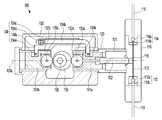
도 1은 본 발명의 실시예에 따른 무맥동 정량펌프의 측면도,
도 2는 본 발명의 실시예에 따른 무맥동 정량펌프의 평면도,
도 3은 제1 및 제2 롤러 팔로워(132a, 132b)와 캠(135)이 접지된 상태로, 캠(135)이 회전하는 양상을 나타낸 모식도,
도 4는 캠(135)의 회전에 따른 플런저(122)의 위치변화(변위)를 세로축으로, 캠(135)의 회전각도를 가로축으로 설정하고 캠(135)의 회전에 따른 플런저(122)의 변위를 나타낸 그래프(A: 제1 구동부, B: 제1 구동부~제3 구동부 병합),
도 5는 본 발명에 따른 무맥동 정량펌프의 토출 및 흡입공정을 모사한 도면(A: 토출공정, B: 흡입공정).1 is a side view of a pulsating flow rate metering pump according to an embodiment of the present invention,
2 is a plan view of a pulsating flow rate measuring pump according to an embodiment of the present invention,
3 is a schematic view showing a state in which the
4 is a graph showing the relationship between the position of the
5 is a diagram simulating the discharging and sucking processes of the pulsating flow rate measuring pump according to the present invention (A: discharging process, and B: sucking process).
이하에서는 본 발명의 바람직한 실시예를 첨부한 도면을 참고하여 상세하게 설명한다. 본 발명을 설명함에 있어서 관련된 공지 기술에 대한 구체적인 설명이 본 발명의 요지를 흐리게 할 수 있다고 판단되는 경우 그 상세한 설명을 생략하기로 한다. 도면에서 본 발명을 명확하게 설명하기 위하여 설명과 관계없는 부분은 생략하였고, 명세서 전체를 통하여 유사한 부분에 대해서는 유사한 도면 부호를 부여하였으며, 세부구성 방향은 도면을 기준으로 하여 설명한다. 또한, 명세서 전체에서, 어떤 부분이 어떤 구성요소를 "포함"한다고 할 때, 이는 특별히 반대되는 기재가 없는 한, 다른 구성요소를 제외하는 것이 아니라 다른 구성요소를 더 포함할 수 있음을 의미한다.Hereinafter, preferred embodiments of the present invention will be described in detail with reference to the accompanying drawings. DETAILED DESCRIPTION OF THE PREFERRED EMBODIMENTS Hereinafter, exemplary embodiments of the present invention will be described in detail with reference to the accompanying drawings. In order to clearly explain the present invention, parts not related to the description are omitted, and similar parts are denoted by similar reference numerals throughout the specification, and detailed configuration directions will be described with reference to the drawings. Also, throughout the specification, when an element is referred to as "comprising ", it means that it can include other elements, not excluding other elements, unless specifically stated otherwise.
본 발명자는 맥동을 제거하기 위해서는 에어챔버(Air Chamber), 댐퍼(Damper)와 같은 맥동 방지 장치가 추가로 설치되야 했던 종래 정량펌프의 문제점을 해결하기 위하여 예의 연구를 거듭한 결과, 120°의 위상차를 갖는 3개의 캠의 운동에 의해 플런저가 슬라이딩 운동을 함으로써, 유체가 흡입/토출관에서 무맥동 파형을 이루며 정량의 유체가 공급되도록 하는 플런저 타입 무맥동 정량펌프를 제공할 수 있음을 발견하고 본 발명을 완성하게 되었다.The inventor of the present invention has conducted intensive studies to solve the problem of a conventional metering pump in which a pulsation prevention device such as an air chamber and a damper has to be additionally installed in order to remove pulsation, Type plunger type pulsating pump capable of supplying a predetermined amount of fluid by making the plunger slide in the direction of movement of the three cams having the pulsation waveform of the suction / Thereby completing the invention.
따라서, 본 발명은 상기 무맥동 정량펌프는 (i) 상/하단에 형성된 흡입구와 토출구 및 상기 흡입구와 토출구를 연결하는 가압실을 포함하는 헤드부;Accordingly, the pulsating pump of the present invention is characterized in that (i) the head portion includes a suction port formed at the upper / lower end thereof, a discharge port, and a pressure chamber connecting the suction port and the discharge port;
(ii) 상기 헤드부와 연결되며 플런저가 실린더 축방향으로 슬라이딩 운동을 하는 실린더부; 및(ii) a cylinder portion connected to the head portion, the plunger slidingly moving in the axial direction of the cylinder; And
(iii) 일단이 상기 플런저와 연결되고 타단이 제1 롤러 팔로워와 연결된 제1 가이드 피스톤; 상기 제1 가이드 피스톤과 행거 로드에 의해 연결되어 상기 제1 가이드 피스톤과 일체로 실린더 축방향으로 왕복 운동을 하는 제2 가이드 피스톤; 상기 제2 가이드 피스톤의 제1 가이드 피스톤 방향 일단과 연결되는 제2 롤러 팔로워; 및 지면과 수평하고 상기 실린더의 축방향과 수직으로 고정된 캠축에 고정되며, 상기 제1 롤러 팔로워 및 제2 롤러 팔로워와 접하는 캠을 포함하는 운동부(iii) a first guide piston having one end connected to the plunger and the other end connected to the first roller follower; A second guide piston connected to the first guide piston by a hanger rod and reciprocating in a cylinder axial direction integrally with the first guide piston; A second roller follower connected to one end of the second guide piston in a first guide piston direction; And a cam fixed to the camshaft, the camshaft being perpendicular to the axial direction of the cylinder, the camshaft being in contact with the first roller follower and the second roller follower,
를 포함하는 제1 구동부,A first driving unit including a first driving unit,
상기 제1 구동부의 각 구성을 동일하게 포함하며 상기 제1 구동부와 수평하게 위치하는 제2 구동부 및 제3 구동부를 포함하며,And a second driving unit and a third driving unit, each of which includes the same configuration of the first driving unit and is positioned horizontally with respect to the first driving unit,
상기 제1 구동부, 제2 구동부 및 제3 구동부의 각각의 캠은 캠축을 공유하고, 캠축이 정지되어 있는 상태를 기준으로 캠축의 중심을 지나는 캠의 중앙선과 실린더 축과의 각도차가 상호간에 120°가 되도록 캠축에 고정이 되어 있는 무맥동 정량펌프를 제공한다.The cams of the first, second, and third driving units share the camshaft, and the angular difference between the center line of the cam passing through the center of the camshaft and the cylinder axis is 120 deg. Pulsation metering pump is fixed to the camshaft so as to be able to rotate the camshaft.
이하, 실시예를 들어 본 발명에 따른 무맥동 정량펌프에 대해 상세히 설명한다.Hereinafter, the non-pulsating metering pump according to the present invention will be described in detail with reference to examples.
도 1은 본 발명의 실시예에 따른 무맥동 정량펌프의 측면도이고, 도 2는 본 발명의 실시예에 따른 무맥동 정량펌프의 평면도이다.1 is a side view of a pulsating flow rate measuring pump according to an embodiment of the present invention, and FIG. 2 is a plan view of a pulsating flow rate measuring pump according to an embodiment of the present invention.
도 1 및 도 2를 참조하면, 본 발명의 실시예에 따른 무맥동 정량펌프는 제1 구동부(100), 제2 구동부(200) 및 제3 구동부(300)를 포함한다. 상기 제1 구동부(100), 제2 구동부(200) 및 제3 구동부(300)를 구성하고 있는 모든 구성요소는 동일하며, 각각은 수평한 방향으로 설치된다. 다만, 상기 각각의 구동부에 포함되는 캠(135)이 캠축(136)에 고정되는 각도가 상이하며, 이에 대한 자세한 내용은 후술하기로 한다.Referring to FIGS. 1 and 2, the pulsating pump of the present invention includes a
상기 제1 구동부는 헤드부(110), 실린더부(120) 및 운동부(130)을 포함한다.The first driving part includes a
상기 헤드부(110)는 유체가 유입되는 통로인 흡입관(111), 상기 흡입관을 통해 유입되는 유체의 흐름을 제어하는 흡입구(112), 상기 흡입구를 통해 헤드부로 유입된 유체가 이동하는 이동관(113), 상기 이동관(113)을 통해 유체가 토출되는 것을 제어하는 토출구(114), 상기 토출구(114)를 통해 토출된 유체가 흘러나가는 토출관(115) 및 플런저(122)의 왕복운동에 의해 헤드부(110) 내 유체의 압력이 조절되는 가압실(116)을 포함한다.The
상기 흡입구(112)는 흡입체크볼(112a)과 흡입체크볼시트(112b)을 포함하며, 상기 흡입체크볼(112a)이 상기 흡입볼시트(112b)과 접촉하고 있는 경우 유체의 흐름이 차단될 수 있고, 상기 흡입체크볼(112a)이 상승하여 상기 흡입체크볼시트(112b)으로부터 분리되는 경우 유체가 흡입체크볼시트(112b)을 통해 헤드부로 유입이 될 수 있다.The
상기 토출구(114)는 토출체크볼(114a) 및 토출체크볼시트(114b)을 포함하며, 상기 흡입구(112)의 흡입체크볼(112a) 및 흡입체크볼시트(112b)과 마찬가지의 원리로 유체의 토출을 제어할 수 있다.The
상기 흡입구(112)와 토출구(113)는 이동관(113)으로 연결이 되어 유체가 이동을 할 수 있고, 상기 이동관(113)은 가압실(116)과 연결이 될 수 있다.The
상기 가압실(116)은 플런저(122)의 이동통로 역할 및 흡입구(112)와 이동관(113)을 통해 헤드부로 유입된 유체가 머무르는 공간으로, 플런저(122)가 헤드부(110) 방향으로 슬라이딩 운동을 할 때 상기 가압실(116) 및 이동관(113)에 머무르는 유체에 압력을 발생시키는 역할을 할 수 있다.The pressurizing
상기 실린더부(120)는 실린더벽(121)과 플런저(122)를 포함한다.The
상기 실린더벽(121)은 헤드부(110) 및 운동부(130)과 연결되어 있으며, 플런저(122)가 이동하는 통로의 역할을 할 수 있다.The
상기 운동부(130)는 플런저(122)의 실린더 축(120a) 방향 슬라이딩 운동을 유발시키는 역할을 하며, 일단이 상기 플런저(122)와 연결되고 타단에는 제1 롤러 팔로워가 고정되어 있는 제1 가이드 피스톤(131a), 상기 제1 가이드 피스톤(131a)과 행거로드(134)에 의해 연결되어 일체로 왕복운동을 하며, 일단에 제2 롤러 팔로워가 고정되어 있는 제2 가이드 피스톤(131b), 상기 제1 가이드 피스톤의 일단에서 제1 롤러 팔로워 축(133a)에 의해 고정되어 제자리 회전을 할 수 있는 제1 롤러 팔로워(132a), 상기 제2 가이드 피스톤의 일단에서 제2 롤러 팔로워 축(133b)에 의해 고정되어 회전할 수 있는 제2 롤러 팔로워(132b), 지면과 수평하고 실린더 축(120a)과 수직인 방향으로 설치되는 캠축(136)에 고정되어 있는 캠(135), 모터와 연결되어 상기 캠축(136)의 회전운동을 발생시키는 모터연결부(137) 및 상기 캠축(136)과 접지되어 캠축(136)의 회전운동을 원활하게 하는 캠축 베어링(138)을 포함한다.The moving
상기 제1 가이드 피스톤(131a)의 상단부에는 행거대(134b)가 거치될 수 있는 홈이 형성될 수 있고, 상기 제2 가이드 피스톤(131b)의 상단부에는 행거관(134a)이 거치될 수 있는 홈이 형성될 수 있다. 상기 행거대(134b)와 행거관(134a)은 각각 제1 가이드 피스톤 및 제2 가이드 피스톤의 상부 홈에 거치될 수 있으며, 연결핀(134e)에 의해 각각 제1 가이드 피스톤 및 제2 가이드 피스톤에 고정될 수 있다.The upper end of the
상기 행거로드(134)는 행거관(134a), 행거대(134b), 스프링(134c), 너트(134d) 및 연결핀(134e)을 포함한다. 상기 행거대(134b)는 행거관(134a)에 삽입된 후 너트(134d)에 의해 행거관(134a)과 견고하게 결합이 될 수 있으며, 상기 행거대(134b)와 상기 너트(134d) 사이에는 스프링(134c)이 삽입되어 기계적인 단차나 설계상의 오차를 보완할 수 있다. 상기 행거로드(134)가 제1 가이드 피스톤(131a) 및 제2 가이드 피스톤(131b)에 결착이 된 이후에는 제1 가이드 피스톤(131a)과 제2 가이드 피스톤(131b)은 일체로서 왕복운동을 수행할 수 있다.The
도 3은 제1 및 제2 롤러 팔로워(132a, 132b)와 캠(135)이 접지된 상태로, 캠(135)이 회전하는 양상을 나타낸 모식도이다. 어느 특정 시점에서 캠(135)의 회전중심(135d)을 지나고 실린더 축(120a)과 평행한 기준선의 각도를 0°라고 가정했을 때, 캠(135)이 회전한 이후의 또 다른 시점에서 상기 기준선이 실린더 축(120a)과 이루는 각도를 도 3에 표시하였다. 도 3에 나타낸 제1 롤러 팔로워(132a) 및 제2 롤러 팔로워(133b)의 위치는 캠(135)이 회전한 시점에서의 상대적인 위치를 도시한 것이며, 실제 구동부 내에서 제1 및 제2 롤러 팔로워의 위치는 고정되어 있다.3 is a schematic diagram showing the manner in which the
도 1 및 도 3을 참조하면, 제1 가이드 피스톤(131a)의 일단에 고정되어 제자리 회전을 할 수 있는 제1 롤러 팔로워(132a)와 제2 가이드 피스톤(131b)의 일단에 고정되어 제자리 회전을 할 수 있는 제2 롤러 팔로워(132b)는 캠(135)의 외면과 접지되며, 상기 캠(135)이 캠축(136)의 회전운동에 의해 회전함에 따라, 상기 제1 및 제2 롤러 팔로워(132a, 132b)도 캠(135)의 외면을 따라 제자리에서 회전을 할 수 있다. 이때, 상기 제1 롤러 팔로워를 고정하고 있는 제1 롤러 팔로워 축(133a)과 제2 롤러 팔로워를 고정하고 있는 제2 캠 팔로워 축(133b)간의 거리(L)는 어느 순간에나 항상 일정하게 유지될 수 있도록 캠(135)의 외면을 설계한다. 또한, 캠의 회전중심(135a)과 제1 롤러 팔로워 축(133a)을 연결하는 직선과, 캠의 회전중심(135a)과 제2 롤러 팔로워 축(133b)를 연결하는 직선이 이루는 각도(θ2-θ1)는 항상 180℃ 일 수 있다.Referring to FIGS. 1 and 3, a
한편, 상기 캠축(136)은 지면과 수평하고 실린더 축(120a)과 수직인 방향으로 설치되어 회전운동을 할 수 있다. 상기 캠축(136)의 중심부는 실린더 축(120a) 선상에 위치하되, 캠(136)의 중심부를 기준으로 제1 롤러 팔로워(132a) 또는 제2 롤러 팔로워(132b) 방향으로 치우치게 고정이 될 수 있다. 바람직하게는, 캠축(136)의 중심과 제1 롤러 팔로워(132a) 중심과의 거리: 캠축(136)의 중심과 제2 롤러 팔로워(132b) 중심과의 거리비는 1: 1.3 ~ 2.4일 수 있으며, 가장 바람직하게는 1 : 1.5일 수 있다. 또한, 제1 구동부, 제2 구동부 및 제3 구동부의 각각의 캠은 캠축을 공유하고, 캠축이 정지되어 있는 상태를 기준으로 캠축의 중심을 지나는 캠의 중앙선과 실린더 축과의 각도차가 상호간에 120°가 되도록 캠축에 고정이 되어 있을 수 있다. 따라서, 특정 시점에서의 정지상태를 기준으로 각각의 캠(135)의 변위가 상이할 수 있다.On the other hand, the
캠(135)이 회전하면, 캠(135)의 외면에 접지되어 있는 한 쌍의 롤러 팔로워(132a, 132b)가 실린더 축(120a) 선상에서 왕복운동을 하게 되고, 이로 인해 캠의 회전운동이 롤러 팔로워(132a, 132b), 가이드 피스톤(131a, 131b) 및 플런저(122)의 왕복운동으로 전환이 될 수 있다. 제1 롤러 팔로워(131a)와 제2 롤러 팔로워(131b)는 행거로드(134)에 의해 고정이 되어 있기 때문에 캠(135)의 회전에 따라 왕복 어느 방향으로도 플런저(122)를 이동시킬 수 있다.When the
이하, 도 4 및 도 5를 참조하여 본 발명에 따른 무맥동 정량펌프의 사용 및 기능 구현에 대해 설명한다.Hereinafter, the use and function of the pulsatile metering pump according to the present invention will be described with reference to FIGS. 4 and 5. FIG.
도 4는 캠(135)의 회전에 따른 플런저(122)의 위치변화를 세로축으로, 캠(135)의 회전각도를 가로축으로 나타낸 그래프이다. 구체적으로, 도 4A는 제1 구동부(100)의 캠(135)의 회전에 따른 플런저(122)의 위치변화, 속도 및 가속도의 변화를 나타낸 그래프이며, 도 4B는 제1 구동부(100) 내지 제3 구동부(300)의 각각의 캠의 회전각도에 따른 플런저(122)의 위치변화를 병합하여 나타낸 그래프이다.4 is a graph showing the change in position of the
도 4A를 참조하면, 캠(135)의 운동은 크게 보면 캠(135)의 회전각이 증가함에 따라 플런저(122)의 변위가 증가하는 상승영역(즉, θ=0~180°)과 캠(135)의 회전각이 증가함에 따라 플런저(122)의 변위가 감소하는 하강영역(즉, θ=180~360°)으로 구분될 수 있다. 플런저(122)의 변위가 증가하는 상승영역(즉, θ=0~180°)을 세분화하면 캠(135)의 회전각이 증가함에 따라 플런저(122)의 변위가 변화지 않는 정지구간1(즉, θ=0~5°), 등가속도로 증가하는 상승영역1(즉, θ=5~55°), 등속도로 증가하는 상승영역2(즉, θ=55~125°), 등감속도로 증가하는 상승영역3(즉, θ=125~175°), 변화지 않는 정지구간2 (즉, θ=175~180°) 으로 구분될 수 있다.Referring to FIG. 4A, the movement of the
즉, 상기 상승영역에서는 캠(135)이 회전함에 따라서 플런저(122)가 실린더 벽(121)을 따라 헤드부(110) 방향으로 이동하여 변위가 상승하며, 상기 하강영역에서는 캠(135)이 회전함에 따라서 플런저(122)가 실린더 벽(121)을 따라 운동부(130) 방향으로 이동하여 변위가 감소하는 것이다. 상기 상승영역과 하강영역은 선대칭 구조를 이룰 수 있다. 한편, 상기 상승영역은 플런저(122)의 변위가 가속적으로 변화하는 가속부(즉, θ=5~55°), 변위가 등속적으로 변화하는 등속부(즉, θ=55~125°) 및 변위가 감속적으로 변화하는 감속부(즉, θ=125~175°)를 포함할 수 있다. 또한 흡입체크볼(112a)과 토출체크볼(114a)의 원활한 작동을 위하여 정지구간1(즉, θ=0~5°)과 정지구간2(즉, θ=175~180°)을 둘 수 있다.That is, in the rising region, as the
도 4B를 참조하면, 상기 도 4A에서 설명한 제1 구동부의 운동원리는 120°의 위상차를 두고 제2 및 제3 구동부에도 동일하게 적용된다. 상기 가속부의 단위 회전 당 변위 변화(즉,△h1/△θ)와 감속부에 대응하는 단위 회전 당 변위 변화(즉, △h2/△θ)의 합은 등속부의 단위 회전 당 변위 변화(즉, △h/△θ)와 동일하도록 캠(135)을 설계하는 것이 바람직하다. 즉, 도 4B의 (I) 영역에 속하는 모든 각도 위치에서 △h1+△h2=△h의 관계가 성립할 수 있다.Referring to FIG. 4B, the principle of motion of the first driver illustrated in FIG. 4A is applied to the second and third drivers with a phase difference of 120 degrees. The sum of the displacement change per unit revolution (i.e., DELTA h1 / DELTA [theta]) of the acceleration portion and the displacement change per unit revolution (i.e., DELTA h2 / DELTA h / DELTA &thetas;). That is, the relation of? H1 +? H2 =? H can be established at all angular positions belonging to the region (I) of FIG. 4B.
도 5는 본 발명에 따른 무맥동 정량펌프의 토출 및 흡입공정을 간략하게 모사한 도면이다. 보다 구체적으로, 도 5A는 도 4의 그래프에서 캠(135)의 회전각도가 0°인 상태일 때의 정지상태를 나타낸 도면이며, 도 5B는 도 4의 그래프에서 캠(135)의 회전각도가 180°인 상태일 때의 정지상태를 나타낸 도면이다.5 is a view schematically illustrating the discharging and sucking process of the pulsating flow rate measuring pump according to the present invention. More specifically, FIG. 5A is a view showing a still state when the rotation angle of the
도 4 및 도 5를 참조하면, 실린더 축(120a)과 수평하게 슬라이딩 운동이 가능한 플런저(122)는 캠(135)이 0°에서 180°방향으로 회전함에 따라 변위가 상승하여, 즉, 헤드부 방향으로 슬라이딩 운동을 하여, 가압실(116) 내부에 존재하는 유체에 압력을 가할 수 있다. 이와 같이, 가압실(116) 내의 유체에 압력이 발생하면 토출 체크볼시트(114b)을 막고 있던 토출 체크볼(114a)이 상승하여 유체가 토출구를 통해 헤드부(110) 외부로 토출될 수 있다. 동시에, 흡입 체크볼(112a)은 유체의 압력에 의해 흡입 체크볼시트(112b)에 밀착하게 되어 흡입구(112)를 통해 유체가 헤드부 내부로 흡입될 수 없다.4 and 5, the displacement of the
반대로, 캠(135)이 180°에서 360° 방향으로 회전을 하면, 플런저(122)의 변위는 감소하여, 즉, 헤드부 반대 방향으로 슬라이딩 운동을 하여, 가압실(116) 내부의 압력이 감소하게 된다. 가압실(116) 내 압력이 감소함에 따라, 흡입 체크볼시트(112b)을 막고 있던 흡입 체크볼(112a)이 상승하게 되고 흡입구를 통해 유체가 헤드부로 유입되어 가압실(116)과 이동관(113)을 채울 수 있다. 동시에, 토출 체크볼(114a)은 감소된 압력에 의해 토출 체크볼시트(114b)에 밀착하게 되어 유체가 토출구(114)를 통해 토출되는 것이 방지될 수 있다.On the contrary, when the
상기와 같은 흡입/토출 공정은, 제1 내지 제3 구동부가 120°의 위상차를 두고 동시에 이루어지게 된다. 보다 구체적으로, 도 4B의 0° 내지 60°구간에서, 제1 구동부(100)의 플런저(135a)는 헤드부(110) 방향으로 등가속적 이동을 하고 있으며, 제2 구동부(200)의 플런저(135b)는 헤드부(110) 반대방향으로 등속적 이동을 하고 있으며, 제3 구동부(300)의 플런저(135c)는 헤드부(110) 방향으로 등감속적 이동을 하고 있다. 이러한 방식으로, 캠의 회전각 60°마다 어느 한 구동부의 플런저(135)는 등속도 운동을, 나머지 두 구동부의 플런저는 등가속 또는 등감속 운동을 나타낸다.In the above-described suction / discharge process, the first to third driving units are simultaneously operated with a phase difference of 120 °. 4B, the
한편, 도 4B의 (I)로 나타낸 0°내지 60°구간에서는 제1 구동부의 플런저(135a)와 제3 구동부의 플런저(135b)가 토출 공정에 있으며 이때의 복합 토출량은 △h1+△h2로 나타낼 수 있다. 또한, 도 4B의 (II)로 나타낸 60°내지 120°구간에서는 제1 구동부의 플런저(135a)만이 토출 공정에 있으며, 이때의 토출량(△Q)는 △H로 표현이 될 수 있다. 상술한 바와 같이 △h1+△h2=△H가 성립하도록 캠(135)의 외면을 설계하였기 때문에, 구간 (I)에서의 토출량과 구간 (II)에서의 토출량은 동일하며, 그 이외의 구간에서도 모두 동일한 토출량을 유지할 수 있다. 마찬가지로, 흡입량 또한 전 구간에서 모두 동일하게 유지될 수 있다.4B, the
이와 같은 방식으로, 본 발명에 따른 무맥동 정량펌프는 어떠한 구간에서라도 흡입량과 토출량이 일정하여 맥동이 형성되지 않을 수 있다.In this way, the pulsation of the pulsating pump of the present invention may not be generated because the suction amount and the discharge amount are constant at any interval.
이상으로 본 발명의 바람직한 실시예를 도면을 참고하여 상세하게 설명하였다. 본 발명의 설명은 예시를 위한 것이며, 본 발명이 속하는 기술분야에서 통상의 지식을 가진 자는 본 발명의 기술적 사상이나 필수적인 특징을 변경하지 않고서 다른 구체적인 형태로 쉽게 변형이 가능하다는 것을 이해할 수 있을 것이다.The preferred embodiments of the present invention have been described in detail with reference to the drawings. It will be understood by those of ordinary skill in the art that various changes in form and details may be made therein without departing from the spirit and scope of the present invention as defined by the appended claims.
따라서, 본 발명의 범위는 상기 상세한 설명보다는 후술하는 청구범위에 의하여 나타내어지며, 청구범위의 의미, 범위 및 그 균등 개념으로부터 도출되는 모든 변경 또는 변형된 형태가 본 발명의 범위에 포함되는 것으로 해석되어야 한다.Accordingly, the scope of the present invention is defined by the appended claims rather than the foregoing detailed description, and all changes or modifications derived from the meaning, range, and equivalence of the claims are to be construed as being included within the scope of the present invention do.
100: 제1 구동부110: 헤드부
111: 흡입관112a: 흡입 체크볼
112b: 흡입 체크볼시트112: 흡입구
113: 이동관114a: 토출 체크볼
114b: 토출 체크볼시트114: 토출구
115: 토출관116: 가압실
120: 실린더부121: 실린더벽
122: 플런저 130: 운동부
131a: 제1 가이드 피스톤131b: 제2 가이드 피스톤
132a: 제1 롤러 팔로워132b: 제2 롤러 팔로워
133a: 제1 롤러 팔로워 축133b: 제2 롤러 팔로워 축
134: 행거로드134a:행거관
134b: 행거대134c: 스프링
134d: 너트134e: 연결핀
135: 캠135a: 제1 구동부 캠
135b: 제2 구동부 캠135c: 제3 구동부 캠
135d: 캠 회전중심
136: 캠축120a: 실린더축
137: 모터연결부138: 캠축 베어링
200: 제2 구동부300: 제3 구동부100: first driving part 110:
111:
112b: Suction check ball seat 112: Suction port
113: moving
114b: Discharge check ball seat 114: Discharge port
115: discharge pipe 116: pressure chamber
120: cylinder part 121: cylinder wall
122: plunger 130:
131a:
132a:
133a: first
134:
134b: hanger stand 134c: spring
134d:
135:
135b: second driving
135d: Cam rotation center
136: camshaft 120a: cylinder shaft
137: motor connection part 138: camshaft bearing
200: second driving part 300: third driving part
Claims (3)
Translated fromKorean(ii) 상기 헤드부와 연결되며 플런저가 실린더 축방향으로 슬라이딩 운동을 하는 실린더부; 및
(iii) 일단이 상기 플런저와 연결되고 타단이 제1 롤러 팔로워와 연결된 제1 가이드 피스톤; 상기 제1 가이드 피스톤과 행거 로드에 의해 연결되어 상기 제1 가이드 피스톤과 일체로 실린더 축방향으로 왕복 운동을 하는 제2 가이드 피스톤; 상기 제2 가이드 피스톤의 제1 가이드 피스톤 방향 일단과 연결되는 제2 롤러 팔로워; 및 지면과 수평하고 상기 실린더의 축방향과 수직으로 설치된 캠축에 고정되며, 상기 제1 롤러 팔로워 및 제2 롤러 팔로워와 접하는 캠을 포함하는 운동부
를 포함하는 제1 구동부,
상기 제1 구동부의 각 구성을 동일하게 포함하며 상기 제1 구동부와 수평하게 위치하는 제2 구동부 및 제3 구동부를 포함하며,
상기 제1 구동부, 제2 구동부 및 제3 구동부의 각각의 캠은 캠축을 공유하고, 캠축이 정지되어 있는 상태를 기준으로 캠축의 중심을 지나는 캠의 중앙선과 실린더 축과의 각도차(θ)가 상호간에 120°가 되도록 캠축에 고정이 되어 있는 무맥동 정량펌프로서,
상기 플런저의 변위가 가속적으로 변화하는 가속부(θ=5~55°)에서 캠의 단위 회전 당 플런저의 변위 변화(△h1)와 상기 플런저의 변위가 감속적으로 변화하는 감속부(θ=125~175°)에서 캠의 단위 회전 당 플런저의 변위 변화(△h2)의 합이 상기 플런저의 변위가 등속적으로 변화하는 등속부(θ= 55~125°)에서 캠의 단위 회전 당 플런저의 변위 변화(△h)와 항상 동일하도록 상기 캠의 외면이 설계된 것을 특징으로 하는 무맥동 정량펌프.
(i) a head portion including a suction port formed at an upper / lower end thereof, a discharge port, and a pressure chamber connecting the suction port and the discharge port;
(ii) a cylinder portion connected to the head portion, the plunger slidingly moving in the axial direction of the cylinder; And
(iii) a first guide piston having one end connected to the plunger and the other end connected to the first roller follower; A second guide piston connected to the first guide piston by a hanger rod and reciprocating in a cylinder axial direction integrally with the first guide piston; A second roller follower connected to one end of the second guide piston in a first guide piston direction; And a cam fixed to the camshaft, the camshaft being perpendicular to the axial direction of the cylinder, the camshaft being in contact with the first roller follower and the second roller follower,
A first driving unit including a first driving unit,
And a second driving unit and a third driving unit, each of which includes the same configuration of the first driving unit and is positioned horizontally with respect to the first driving unit,
The cams of the first, second, and third driving units share a camshaft, and the angle difference between the center line of the cam passing through the center of the camshaft and the cylinder axis is θ Pulsating metering pump fixed to a camshaft so as to be 120 DEG with respect to each other,
(? H1) of the plunger per unit rotation of the cam and a decelerating portion (? = H1) at which the displacement of the plunger decelerates at an acceleration portion (? = 5 to 55 占 where the displacement of the plunger accelerates, 125 to 175 deg.), The sum of displacement changes (DELTA h2) of the plungers per unit rotation of the cam is equal to or smaller than the sum of the displacements of the plungers per unit rotation of the cam Wherein the outer surface of the cam is designed to be always equal to the displacement change? H.
2. The pulsating pump according to claim 1, wherein the outer surface of the cam is designed so that an axis distance between the axis of the first roller follower and the axis of the second roller follower is always constant.
2. The image forming apparatus according to claim 1, wherein the distance between the center of the camshaft and the center of the first roller follower: the distance between the center of the camshaft and the center of the second roller follower is 1: 1.3 to 2.4. Pulsatile dosing pump.
Priority Applications (1)
| Application Number | Priority Date | Filing Date | Title |
|---|---|---|---|
| KR1020170058821AKR101823607B1 (en) | 2017-05-11 | 2017-05-11 | Plunger type pulse free metering pump |
Applications Claiming Priority (1)
| Application Number | Priority Date | Filing Date | Title |
|---|---|---|---|
| KR1020170058821AKR101823607B1 (en) | 2017-05-11 | 2017-05-11 | Plunger type pulse free metering pump |
Publications (1)
| Publication Number | Publication Date |
|---|---|
| KR101823607B1true KR101823607B1 (en) | 2018-01-31 |
Family
ID=61082908
Family Applications (1)
| Application Number | Title | Priority Date | Filing Date |
|---|---|---|---|
| KR1020170058821AActiveKR101823607B1 (en) | 2017-05-11 | 2017-05-11 | Plunger type pulse free metering pump |
Country Status (1)
| Country | Link |
|---|---|
| KR (1) | KR101823607B1 (en) |
Cited By (1)
| Publication number | Priority date | Publication date | Assignee | Title |
|---|---|---|---|---|
| KR20220161913A (en) | 2021-05-31 | 2022-12-07 | 주식회사 바이온텍 | Micro metering pump |
Citations (2)
| Publication number | Priority date | Publication date | Assignee | Title |
|---|---|---|---|---|
| KR101245670B1 (en)* | 2003-12-20 | 2013-03-20 | 아이티더블유 리미티드 | Pumps |
| KR101670272B1 (en)* | 2016-07-29 | 2016-10-31 | (주)진양비지엠텍 | Grouting pump |
- 2017
- 2017-05-11KRKR1020170058821Apatent/KR101823607B1/enactiveActive
Patent Citations (2)
| Publication number | Priority date | Publication date | Assignee | Title |
|---|---|---|---|---|
| KR101245670B1 (en)* | 2003-12-20 | 2013-03-20 | 아이티더블유 리미티드 | Pumps |
| KR101670272B1 (en)* | 2016-07-29 | 2016-10-31 | (주)진양비지엠텍 | Grouting pump |
Cited By (1)
| Publication number | Priority date | Publication date | Assignee | Title |
|---|---|---|---|---|
| KR20220161913A (en) | 2021-05-31 | 2022-12-07 | 주식회사 바이온텍 | Micro metering pump |
Similar Documents
| Publication | Publication Date | Title |
|---|---|---|
| KR950007514B1 (en) | Valveless positive displacement metering pump | |
| US3301197A (en) | Pump | |
| US9506458B2 (en) | Liquid supply apparatus | |
| TWI791800B (en) | Non-pulsation pump and control method for the non-pulsation pump | |
| CN102207066B (en) | A double-acting plunger pump | |
| AU2009309375A1 (en) | A volumetric pump and its driving mechanism | |
| CN105765220A (en) | Spin pump with spun-epicyclic geometry | |
| US3323461A (en) | Metering pump | |
| KR101823607B1 (en) | Plunger type pulse free metering pump | |
| US20240018952A1 (en) | In and Relating to Pumps | |
| JPH04224278A (en) | Reciprocating plunger pump | |
| US7207780B2 (en) | Multiple port dual diameter pumps | |
| CN106499608A (en) | The grooved cam that a kind of servomotor drives declines flow plunger displacement pump | |
| RU2682302C1 (en) | High pressure pump for injecting high-viscosity material | |
| JPS61178569A (en) | Control method of liquid feeding pump | |
| KR100888266B1 (en) | Tripulsationless pulsation metering pump and control method using constant velocity cam | |
| CN210977788U (en) | Reciprocating linkage double-cam plunger pump | |
| JPH07197880A (en) | Plunger type liquid delivery pump | |
| JPH05501138A (en) | pulseless piston pump | |
| JP2013119800A (en) | Plunger pump | |
| CN219317124U (en) | Reciprocating flow pump | |
| JP6732569B2 (en) | Pump mechanism and fluid supply device | |
| JP2001132621A (en) | Pump device | |
| CN219681337U (en) | Low-disturbance pulse pump | |
| CN110761968A (en) | Reciprocating linkage double-cam plunger pump |
Legal Events
| Date | Code | Title | Description |
|---|---|---|---|
| PA0109 | Patent application | Patent event code:PA01091R01D Comment text:Patent Application Patent event date:20170511 | |
| PA0201 | Request for examination | ||
| PA0302 | Request for accelerated examination | Patent event date:20171027 Patent event code:PA03022R01D Comment text:Request for Accelerated Examination Patent event date:20170511 Patent event code:PA03021R01I Comment text:Patent Application | |
| PE0902 | Notice of grounds for rejection | Comment text:Notification of reason for refusal Patent event date:20171115 Patent event code:PE09021S01D | |
| E701 | Decision to grant or registration of patent right | ||
| PE0701 | Decision of registration | Patent event code:PE07011S01D Comment text:Decision to Grant Registration Patent event date:20180118 | |
| GRNT | Written decision to grant | ||
| PR0701 | Registration of establishment | Comment text:Registration of Establishment Patent event date:20180124 Patent event code:PR07011E01D | |
| PR1002 | Payment of registration fee | Payment date:20180125 End annual number:3 Start annual number:1 | |
| PG1601 | Publication of registration | ||
| PR1001 | Payment of annual fee | Payment date:20210111 Start annual number:4 End annual number:4 | |
| PR1001 | Payment of annual fee | Payment date:20220120 Start annual number:5 End annual number:5 | |
| PR1001 | Payment of annual fee | Payment date:20230110 Start annual number:6 End annual number:6 | |
| PR1001 | Payment of annual fee | Payment date:20240110 Start annual number:7 End annual number:7 | |
| PR1001 | Payment of annual fee | Payment date:20250124 Start annual number:8 End annual number:8 |