KR101821837B1 - Point of sale inductive systems and methods - Google Patents
Point of sale inductive systems and methodsDownload PDFInfo
- Publication number
- KR101821837B1 KR101821837B1KR1020127029398AKR20127029398AKR101821837B1KR 101821837 B1KR101821837 B1KR 101821837B1KR 1020127029398 AKR1020127029398 AKR 1020127029398AKR 20127029398 AKR20127029398 AKR 20127029398AKR 101821837 B1KR101821837 B1KR 101821837B1
- Authority
- KR
- South Korea
- Prior art keywords
- product
- delete delete
- circuit
- inductive
- impedance
- Prior art date
- Legal status (The legal status is an assumption and is not a legal conclusion. Google has not performed a legal analysis and makes no representation as to the accuracy of the status listed.)
- Expired - Fee Related
Links
Images


Classifications
- G—PHYSICS
- G06—COMPUTING OR CALCULATING; COUNTING
- G06K—GRAPHICAL DATA READING; PRESENTATION OF DATA; RECORD CARRIERS; HANDLING RECORD CARRIERS
- G06K7/00—Methods or arrangements for sensing record carriers, e.g. for reading patterns
- G06K7/08—Methods or arrangements for sensing record carriers, e.g. for reading patterns by means detecting the change of an electrostatic or magnetic field, e.g. by detecting change of capacitance between electrodes
- G06K7/082—Methods or arrangements for sensing record carriers, e.g. for reading patterns by means detecting the change of an electrostatic or magnetic field, e.g. by detecting change of capacitance between electrodes using inductive or magnetic sensors
- G06K7/083—Methods or arrangements for sensing record carriers, e.g. for reading patterns by means detecting the change of an electrostatic or magnetic field, e.g. by detecting change of capacitance between electrodes using inductive or magnetic sensors inductive
- G06K7/086—Methods or arrangements for sensing record carriers, e.g. for reading patterns by means detecting the change of an electrostatic or magnetic field, e.g. by detecting change of capacitance between electrodes using inductive or magnetic sensors inductive sensing passive circuit, e.g. resonant circuit transponders
- D—TEXTILES; PAPER
- D06—TREATMENT OF TEXTILES OR THE LIKE; LAUNDERING; FLEXIBLE MATERIALS NOT OTHERWISE PROVIDED FOR
- D06F—LAUNDERING, DRYING, IRONING, PRESSING OR FOLDING TEXTILE ARTICLES
- D06F93/00—Counting, sorting, or marking arrangements specially adapted for laundry purposes
- D06F93/005—Marking arrangements
- G—PHYSICS
- G01—MEASURING; TESTING
- G01F—MEASURING VOLUME, VOLUME FLOW, MASS FLOW OR LIQUID LEVEL; METERING BY VOLUME
- G01F23/00—Indicating or measuring liquid level or level of fluent solid material, e.g. indicating in terms of volume or indicating by means of an alarm
- G01F23/20—Indicating or measuring liquid level or level of fluent solid material, e.g. indicating in terms of volume or indicating by means of an alarm by measurement of weight, e.g. to determine the level of stored liquefied gas
- G—PHYSICS
- G01—MEASURING; TESTING
- G01F—MEASURING VOLUME, VOLUME FLOW, MASS FLOW OR LIQUID LEVEL; METERING BY VOLUME
- G01F23/00—Indicating or measuring liquid level or level of fluent solid material, e.g. indicating in terms of volume or indicating by means of an alarm
- G01F23/22—Indicating or measuring liquid level or level of fluent solid material, e.g. indicating in terms of volume or indicating by means of an alarm by measuring physical variables, other than linear dimensions, pressure or weight, dependent on the level to be measured, e.g. by difference of heat transfer of steam or water
- G01F23/24—Indicating or measuring liquid level or level of fluent solid material, e.g. indicating in terms of volume or indicating by means of an alarm by measuring physical variables, other than linear dimensions, pressure or weight, dependent on the level to be measured, e.g. by difference of heat transfer of steam or water by measuring variations of resistance of resistors due to contact with conductor fluid
- G01F23/241—Indicating or measuring liquid level or level of fluent solid material, e.g. indicating in terms of volume or indicating by means of an alarm by measuring physical variables, other than linear dimensions, pressure or weight, dependent on the level to be measured, e.g. by difference of heat transfer of steam or water by measuring variations of resistance of resistors due to contact with conductor fluid for discrete levels
- G01F23/243—Schematic arrangements of probes combined with measuring circuits
- G01F23/244—Schematic arrangements of probes combined with measuring circuits comprising oscillating circuits
- G—PHYSICS
- G01—MEASURING; TESTING
- G01F—MEASURING VOLUME, VOLUME FLOW, MASS FLOW OR LIQUID LEVEL; METERING BY VOLUME
- G01F23/00—Indicating or measuring liquid level or level of fluent solid material, e.g. indicating in terms of volume or indicating by means of an alarm
- G01F23/22—Indicating or measuring liquid level or level of fluent solid material, e.g. indicating in terms of volume or indicating by means of an alarm by measuring physical variables, other than linear dimensions, pressure or weight, dependent on the level to be measured, e.g. by difference of heat transfer of steam or water
- G01F23/26—Indicating or measuring liquid level or level of fluent solid material, e.g. indicating in terms of volume or indicating by means of an alarm by measuring physical variables, other than linear dimensions, pressure or weight, dependent on the level to be measured, e.g. by difference of heat transfer of steam or water by measuring variations of capacity or inductance of capacitors or inductors arising from the presence of liquid or fluent solid material in the electric or electromagnetic fields
- G—PHYSICS
- G01—MEASURING; TESTING
- G01G—WEIGHING
- G01G19/00—Weighing apparatus or methods adapted for special purposes not provided for in the preceding groups
- G01G19/40—Weighing apparatus or methods adapted for special purposes not provided for in the preceding groups with provisions for indicating, recording, or computing price or other quantities dependent on the weight
- G01G19/413—Weighing apparatus or methods adapted for special purposes not provided for in the preceding groups with provisions for indicating, recording, or computing price or other quantities dependent on the weight using electromechanical or electronic computing means
- G01G19/414—Weighing apparatus or methods adapted for special purposes not provided for in the preceding groups with provisions for indicating, recording, or computing price or other quantities dependent on the weight using electromechanical or electronic computing means using electronic computing means only
- G01G19/4144—Weighing apparatus or methods adapted for special purposes not provided for in the preceding groups with provisions for indicating, recording, or computing price or other quantities dependent on the weight using electromechanical or electronic computing means using electronic computing means only for controlling weight of goods in commercial establishments, e.g. supermarket, P.O.S. systems
- G—PHYSICS
- G01—MEASURING; TESTING
- G01G—WEIGHING
- G01G7/00—Weighing apparatus wherein the balancing is effected by magnetic, electromagnetic, or electrostatic action, or by means not provided for in the preceding groups
- G—PHYSICS
- G06—COMPUTING OR CALCULATING; COUNTING
- G06K—GRAPHICAL DATA READING; PRESENTATION OF DATA; RECORD CARRIERS; HANDLING RECORD CARRIERS
- G06K19/00—Record carriers for use with machines and with at least a part designed to carry digital markings
- G06K19/06—Record carriers for use with machines and with at least a part designed to carry digital markings characterised by the kind of the digital marking, e.g. shape, nature, code
- G06K19/067—Record carriers with conductive marks, printed circuits or semiconductor circuit elements, e.g. credit or identity cards also with resonating or responding marks without active components
- G06K19/0672—Record carriers with conductive marks, printed circuits or semiconductor circuit elements, e.g. credit or identity cards also with resonating or responding marks without active components with resonating marks
- G—PHYSICS
- G06—COMPUTING OR CALCULATING; COUNTING
- G06K—GRAPHICAL DATA READING; PRESENTATION OF DATA; RECORD CARRIERS; HANDLING RECORD CARRIERS
- G06K19/00—Record carriers for use with machines and with at least a part designed to carry digital markings
- G06K19/06—Record carriers for use with machines and with at least a part designed to carry digital markings characterised by the kind of the digital marking, e.g. shape, nature, code
- G06K19/067—Record carriers with conductive marks, printed circuits or semiconductor circuit elements, e.g. credit or identity cards also with resonating or responding marks without active components
- G06K19/07—Record carriers with conductive marks, printed circuits or semiconductor circuit elements, e.g. credit or identity cards also with resonating or responding marks without active components with integrated circuit chips
- G06K19/0716—Record carriers with conductive marks, printed circuits or semiconductor circuit elements, e.g. credit or identity cards also with resonating or responding marks without active components with integrated circuit chips at least one of the integrated circuit chips comprising a sensor or an interface to a sensor
- G06K19/0717—Record carriers with conductive marks, printed circuits or semiconductor circuit elements, e.g. credit or identity cards also with resonating or responding marks without active components with integrated circuit chips at least one of the integrated circuit chips comprising a sensor or an interface to a sensor the sensor being capable of sensing environmental conditions such as temperature history or pressure
- G—PHYSICS
- G06—COMPUTING OR CALCULATING; COUNTING
- G06K—GRAPHICAL DATA READING; PRESENTATION OF DATA; RECORD CARRIERS; HANDLING RECORD CARRIERS
- G06K19/00—Record carriers for use with machines and with at least a part designed to carry digital markings
- G06K19/06—Record carriers for use with machines and with at least a part designed to carry digital markings characterised by the kind of the digital marking, e.g. shape, nature, code
- G06K19/067—Record carriers with conductive marks, printed circuits or semiconductor circuit elements, e.g. credit or identity cards also with resonating or responding marks without active components
- G06K19/07—Record carriers with conductive marks, printed circuits or semiconductor circuit elements, e.g. credit or identity cards also with resonating or responding marks without active components with integrated circuit chips
- G06K19/0723—Record carriers with conductive marks, printed circuits or semiconductor circuit elements, e.g. credit or identity cards also with resonating or responding marks without active components with integrated circuit chips the record carrier comprising an arrangement for non-contact communication, e.g. wireless communication circuits on transponder cards, non-contact smart cards or RFIDs
- A—HUMAN NECESSITIES
- A47—FURNITURE; DOMESTIC ARTICLES OR APPLIANCES; COFFEE MILLS; SPICE MILLS; SUCTION CLEANERS IN GENERAL
- A47F—SPECIAL FURNITURE, FITTINGS, OR ACCESSORIES FOR SHOPS, STOREHOUSES, BARS, RESTAURANTS OR THE LIKE; PAYING COUNTERS
- A47F10/00—Furniture or installations specially adapted to particular types of service systems, not otherwise provided for
- A47F10/02—Furniture or installations specially adapted to particular types of service systems, not otherwise provided for for self-service type systems, e.g. supermarkets
- B—PERFORMING OPERATIONS; TRANSPORTING
- B05—SPRAYING OR ATOMISING IN GENERAL; APPLYING FLUENT MATERIALS TO SURFACES, IN GENERAL
- B05B—SPRAYING APPARATUS; ATOMISING APPARATUS; NOZZLES
- B05B11/00—Single-unit hand-held apparatus in which flow of contents is produced by the muscular force of the operator at the moment of use
- B05B11/01—Single-unit hand-held apparatus in which flow of contents is produced by the muscular force of the operator at the moment of use characterised by the means producing the flow
- B05B11/10—Pump arrangements for transferring the contents from the container to a pump chamber by a sucking effect and forcing the contents out through the dispensing nozzle
- B05B11/1042—Components or details
- B05B11/1052—Actuation means
- B05B11/1056—Actuation means comprising rotatable or articulated levers
- G—PHYSICS
- G06—COMPUTING OR CALCULATING; COUNTING
- G06F—ELECTRIC DIGITAL DATA PROCESSING
- G06F3/00—Input arrangements for transferring data to be processed into a form capable of being handled by the computer; Output arrangements for transferring data from processing unit to output unit, e.g. interface arrangements
- G06F3/14—Digital output to display device ; Cooperation and interconnection of the display device with other functional units
- G06F3/147—Digital output to display device ; Cooperation and interconnection of the display device with other functional units using display panels
- G—PHYSICS
- G09—EDUCATION; CRYPTOGRAPHY; DISPLAY; ADVERTISING; SEALS
- G09G—ARRANGEMENTS OR CIRCUITS FOR CONTROL OF INDICATING DEVICES USING STATIC MEANS TO PRESENT VARIABLE INFORMATION
- G09G2370/00—Aspects of data communication
- G09G2370/16—Use of wireless transmission of display information
- G—PHYSICS
- G09—EDUCATION; CRYPTOGRAPHY; DISPLAY; ADVERTISING; SEALS
- G09G—ARRANGEMENTS OR CIRCUITS FOR CONTROL OF INDICATING DEVICES USING STATIC MEANS TO PRESENT VARIABLE INFORMATION
- G09G2380/00—Specific applications
- G09G2380/04—Electronic labels
- H—ELECTRICITY
- H01—ELECTRIC ELEMENTS
- H01F—MAGNETS; INDUCTANCES; TRANSFORMERS; SELECTION OF MATERIALS FOR THEIR MAGNETIC PROPERTIES
- H01F21/00—Variable inductances or transformers of the signal type
- H01F21/02—Variable inductances or transformers of the signal type continuously variable, e.g. variometers
- H—ELECTRICITY
- H01—ELECTRIC ELEMENTS
- H01F—MAGNETS; INDUCTANCES; TRANSFORMERS; SELECTION OF MATERIALS FOR THEIR MAGNETIC PROPERTIES
- H01F38/00—Adaptations of transformers or inductances for specific applications or functions
- H01F38/14—Inductive couplings
- Y—GENERAL TAGGING OF NEW TECHNOLOGICAL DEVELOPMENTS; GENERAL TAGGING OF CROSS-SECTIONAL TECHNOLOGIES SPANNING OVER SEVERAL SECTIONS OF THE IPC; TECHNICAL SUBJECTS COVERED BY FORMER USPC CROSS-REFERENCE ART COLLECTIONS [XRACs] AND DIGESTS
- Y10—TECHNICAL SUBJECTS COVERED BY FORMER USPC
- Y10T—TECHNICAL SUBJECTS COVERED BY FORMER US CLASSIFICATION
- Y10T29/00—Metal working
- Y10T29/49—Method of mechanical manufacture
- Y10T29/49002—Electrical device making
Landscapes
- Physics & Mathematics (AREA)
- Engineering & Computer Science (AREA)
- General Physics & Mathematics (AREA)
- Theoretical Computer Science (AREA)
- Fluid Mechanics (AREA)
- Mathematical Physics (AREA)
- Thermal Sciences (AREA)
- Microelectronics & Electronic Packaging (AREA)
- Computer Hardware Design (AREA)
- Electromagnetism (AREA)
- Power Engineering (AREA)
- Computer Vision & Pattern Recognition (AREA)
- Artificial Intelligence (AREA)
- Computer Networks & Wireless Communication (AREA)
- Textile Engineering (AREA)
- Human Computer Interaction (AREA)
- General Engineering & Computer Science (AREA)
- Details Of Rigid Or Semi-Rigid Containers (AREA)
- Measuring Temperature Or Quantity Of Heat (AREA)
- Charge And Discharge Circuits For Batteries Or The Like (AREA)
- Measurement Of Levels Of Liquids Or Fluent Solid Materials (AREA)
- Radar Systems Or Details Thereof (AREA)
- Near-Field Transmission Systems (AREA)
Abstract
Translated fromKoreanDescription
Translated fromKorean본 발명은 POS 및 기타 장소의 유도성(inductive) 시스템 및 방법에 관한 것이다.The present invention relates to POS systems and other inductive systems and methods.
POS 시스템(Point of sale systems)은 일반적으로 일련의 선반 유닛들 및 연관된 표지판(signage)을 포함할 수 있다. 예를 들어, 곤돌라 선반은, 값싸고, 재구성가능하며, 다양한 제품을 디스플레이할 수 있다는 것으로부터 이익을 얻는다. 표지판은 소스 정보, 제품 정보 및/또는 대응하는 제품을 홍보하거나 기타의 방식으로 주목을 끌어낼 수 있는 판매 정보를 포함할 수 있다. 예를 들어, 표지판은 대응하는 선반 유닛에 고정되거나 근접하게 위치한 플래카드를 포함할 수 있다.Point of sale systems may generally include a series of shelf units and associated signage. For example, gondola shelves benefit from being inexpensive, reconfigurable, and capable of displaying a variety of products. The sign may include source information, product information, and / or sales information that can promote the corresponding product or otherwise attract attention. For example, the sign may include a placard fixed or proximate to a corresponding shelf unit.
POS 시스템은 또한 최근의 제품 패키징 개선으로부터 이익을 얻고 있다. 현대의 제품 패키징은, 재고 제어, 위조 방지, 및/또는 무단조작 방지 대책의 한 일환으로서 RFID 라벨을 더욱 더 이용하고 있다. 제품 패키징은 또한, 제품의 사양, 호환성 정보, 전력 요건, 및 하드웨어 요건을 표시하면서도 제품을 위한 안전한 하우징을 제공하는 것을 포함한 추가의 전통적인 기능들도 제공할 수 있다.POS systems also benefit from recent product packaging improvements. Modern product packaging continues to use RFID labels as part of inventory control, anti-counterfeiting, and / or anti-tampering measures. The product packaging may also provide additional traditional functions, including providing a safe housing for the product while displaying product specifications, compatibility information, power requirements, and hardware requirements.
또한, POS 시스템은 제품 재고를 모니터링하기 위해 체크-아웃 단말기망을 포함할 수 있다. 예를 들어, 공지된 재고 제어 시스템은 자기 스트라이프 판독기, 바 코드 판독기, 체크 승인 시스템, 및/또는 위조품 검출 시스템을 갖는 단말기망을 포함한다. 이러한 재고 제어 시스템은 주어진 레벨 이하로 상점 재고가 떨어지거나 제품 수요 증가가 예상될 때 제품을 자동으로 재주문할 수 있다.In addition, the POS system may include a check-out terminal network to monitor product inventory. For example, a known inventory control system includes a terminal network with a magnetic stripe reader, a bar code reader, a check approval system, and / or a counterfeit detection system. Such an inventory control system can automatically reorder the product when a store inventory falls below a given level or when an increase in product demand is anticipated.
전술된 POS 시스템은 널리 수용되고 있지만, 많은 단점을 안고 있다. 예를 들어, 많은 디스플레이 및 패키징 디자인에서 제품과 상호작용하는 능력이 제한되어 있다. 또한, 제품이 장기간 재고 상태를 유지하는 경우, 배터리 충전 소실이 발생할 수 있다. 재고 관리는 통상적으로 체크아웃시에 발생하며 그 전에 발생하는 것은 아니므로, POS에서 제품량의 시각적 검사도 역시 필요해질 수 있다.While the POS system described above is widely accepted, it has many drawbacks. For example, many display and packaging designs have limited ability to interact with the product. Also, if the product maintains a long-term inventory condition, battery charge loss may occur. Inventory management typically occurs at check-out and does not occur before, so visual inspection of product quantities at the POS may also be required.
따라서, POS에서 제품 및 제품 정보를 홍보하기 위한 개선된 시스템 및 방법에 대한 지속적 요구가 남아 있다. 또한, 기존의 재고 관리 시스템의 이익을 활용하고 POS나 가정이나 기타의 장소에서 제품 식별과 자동 재주문을 개선하기 위한 개선된 시스템 및 방법에 대한 지속적 필요성이 남아 있다.Therefore, there is a continuing need for improved systems and methods for promoting product and product information at the POS. There is also a continuing need for improved systems and methods for leveraging the benefits of existing inventory management systems and improving product identification and automatic reordering at POS, home or other locations.
본 발명의 실시예들은 제품 및 제품 패키징의 식별, 전력공급 및 제어를 위한 유도성 시스템 및 방법을 제공한다.Embodiments of the present invention provide an inductive system and method for identification, power supply, and control of product and product packaging.
한 실시예에 따르면, 제품 레벨을 모니터링하기 위한 시스템 및 방법이 제공된다. 이 시스템은, 제품 레벨 센서와, 제품 잔량에 기초하여 임피던스가 변하는 수동 동조 회로를 갖는 제품 용기를 포함할 수 있다. 이 시스템은 수동 동조 회로의 임피던스를 모니터링하기 위해 1차 코일을 갖는 유도성 판독기를 더 포함할 수 있다. 이 시스템은 예를 들어, 액체, 산개된 물품(loose article), 및 시트재의 롤에 대한 제품 레벨을 모니터링하도록 구성될 수 있다. 제품 레벨이 미리 결정된 레벨 아래로 떨어지면, 일부 실시예에서는 추가의 제품량이 자동으로 재주문될 수 있다.According to one embodiment, a system and method for monitoring product level is provided. The system may include a product level sensor and a product container having a passive tuning circuit whose impedance is varied based on the product remaining amount. The system may further include an inductive reader having a primary coil for monitoring the impedance of the passive tuning circuit. The system may be configured to monitor product levels for, for example, liquids, loose articles, and rolls of sheet material. If the product level falls below a predetermined level, additional product quantities may be automatically reordered in some embodiments.
또 다른 실시예에 따르면, 가정, 식당이나 기타의 장소 전반의 다양한 장소에 국지적 유도성 판독기군이 배치된다. 예를 들어, 국지적 판독기군은 냉장고, 세탁실, 약상자, 청소용품실, 및/또는 청소용품 가방에 배치될 수 있다. 유도성 판독기는 제품의 식별자와 제품 잔량 양쪽 모두를 판정하도록 동작할 수 있다. 한 실시예에서, 국지적 유도성 판독기군은 소정 기간 후에 남아 있는 제품량에 기초하여 칼로리 소비를 모니터링할 수 있다. 또 다른 실시예에서, 국지적 유도성 판독기군은 레시피 준비(recipe preparation)를 보조할 수 있다. 역시 또 다른 실시예에서, 국지적 유도성 판독기군은 식료품 저장실이나 기타 장소의 식료품의 잔여 레벨에 기초하여 쇼핑 목록을 생성할 수 있다.According to yet another embodiment, a group of locally inductive readers is deployed at various locations throughout the home, restaurant, or other location. For example, a local reader group may be placed in a refrigerator, laundry room, medicament, cleaning article room, and / or cleaning article bag. The inductive reader may be operable to determine both an identifier of the product and a product remaining amount. In one embodiment, the local inductive reader group can monitor calorie consumption based on the amount of product remaining after a predetermined period of time. In another embodiment, a group of local inductive readers may assist in recipe preparation. In yet another embodiment, the local inductive reader group may generate a shopping list based on the remaining level of the grocery in the pantry or other location.
또 다른 실시예에 따르면, 식료품을 가열하기 위한 시스템 및 방법이 제공된다. 이 시스템은, 제품 용기의 온도에 기초하여 임피던스가 변하는 수동 동조 회로와 온도 센서를 갖는 제품 용기를 포함할 수 있다. 이 시스템은 제품 용기와 연관된 수동 동조 회로의 임피던스를 모니터링하기 위해 1차 코일을 더 포함할 수 있다. 이 시스템은, 온도가 원하는 레벨 아래로 떨어지면 제품 용기와 연관된 가열 소자에 무선 전력 소스를 제공하도록 구성될 수 있다. 일부 실시예들에서, 가열 소자는 시변동 전자기장에 반응하는 강자성 재료를 포함할 수 있다. 다른 실시예들에서, 가열 소자는 2차 탱크 회로에 전기적으로 접속될 수 있다.According to yet another embodiment, a system and method for heating foodstuffs is provided. The system may include a product container having a temperature sensor and a passive tuning circuit whose impedance is varied based on the temperature of the product container. The system may further include a primary coil for monitoring the impedance of the passive tuning circuit associated with the product container. The system may be configured to provide a wireless power source to a heating element associated with the product container when the temperature falls below a desired level. In some embodiments, the heating element may comprise a ferromagnetic material that is responsive to a time-varying electromagnetic field. In other embodiments, the heating element may be electrically connected to the secondary tank circuit.
또 다른 실시예에 따르면, 휴대 가열 기구에 무선 전력 소스를 제공하기 위한 시스템 및 방법이 제공된다. 이 시스템은, 비접촉식 전원과, 2차 코일에 전기적으로 접속된 가열 소자를 포함하는 휴대 기구를 포함할 수 있다. 한 실시예에서, 가열 소자는 강자성 가열 소자이다. 또 다른 실시예에서, 휴대 기구는 코드없는 다리미이고, 비접촉식 전원이 격납가능한 다림판 내에 병합된다. 이 실시예에서, 코드없는 다리미는 유도성 식별 프로파일을 정의하는 수동 식별 회로를 포함할 수 있다.According to yet another embodiment, a system and method for providing a wireless power source to a portable heating mechanism is provided. The system may include a portable device including a non-contact power source and a heating element electrically connected to the secondary coil. In one embodiment, the heating element is a ferromagnetic heating element. In yet another embodiment, the portable device is a cordless iron, and the non-contact power source is incorporated into a housable ironing board. In this embodiment, the cordless irons may include a passive identification circuit that defines an inductive identification profile.
또 다른 실시예에 따르면, 제품 정렬 시스템 및 방법이 제공된다. 이 시스템은 제품이나 제품 용기의 2차 코일에 무선 전력 소스를 제공하기 위한 하나 이상의 1차 코일을 갖는 디스플레이면을 포함할 수 있다. 이 시스템은, 제품이나 제품 용기를 하나 이상의 1차 코일과 정렬된 위치로 보내는 가이드판을 포함할 수 있다. 한 실시예에서, 한 행의 제품 중에서 선두 제품만이 하나 이상의 1차 코일과 정렬될 것이다. 또 다른 실시예에서, 하나 이상의 1차 코일은, 선두 제품이나 제품 용기와 연관된 LED, 스피커, 배터리 또는 기타의 장치에 무선 전력 소스를 제공할 수 있다.According to yet another embodiment, a product alignment system and method are provided. The system may include a display surface having one or more primary coils for providing a wireless power source to a secondary coil of the product or product container. The system may include a guide plate that directs the product or product container to an aligned position with the one or more primary coils. In one embodiment, only one of the products in a row will be aligned with one or more primary coils. In yet another embodiment, the one or more primary coils may provide a wireless power source to an LED, speaker, battery, or other device associated with the lead product or product container.
또 다른 실시예에 따르면, 제품 패키징에 무선 전력 소스를 제공하기 위한 시스템 및 방법이 제공된다. 이 시스템은, 하나 이상의 시각적 소자, 스피커 소자 또는 양쪽 모두에 전기적으로 연결된 2차 탱크 회로를 갖는 제품 용기를 포함할 수 있다. 시각적 소자는, 하나 이상의 LED, OLED, LCD 디스플레이 및 e-잉크 디스플레이를 포함할 수 있고, 스피커 소자는 예를 들어 정전식 스피커를 포함할 수 있다. 한 실시예에서, 2차 탱크 회로는 제품 용기에 부착된 인쇄된 라벨 상에 형성될 수 있다. 인쇄된 라벨은, 부하를 지지하는 상부와 2차 탱크 회로를 지지하는 하부를 포함할 수 있다. 상부는 제품 용기 측벽에 순응하도록 크기조정될 수 있고, 하부는 제품 용기 베이스에 순응하도록 크기조정될 수 있다.According to yet another embodiment, a system and method for providing a wireless power source for product packaging is provided. The system may include a product container having a secondary tank circuit electrically connected to one or more visual elements, a speaker element, or both. The visual element may comprise one or more LEDs, an OLED, an LCD display and an e-ink display, and the speaker element may comprise, for example, an electrostatic speaker. In one embodiment, the secondary tank circuit may be formed on a printed label attached to a product container. The printed label may include an upper portion supporting the load and a lower portion supporting the secondary tank circuit. The top portion may be sized to conform to the product container side wall and the bottom portion may be sized to conform to the product container base.
또 다른 실시예에 따르면, 제품의 무선 식별을 위한 시스템 및 방법이 제공된다. 이 시스템은, 각각이 하나 이상의 공진 회로를 갖는 복수의 제품이나 제품 용기를 포함할 수 있다. 유도성 판독기는, 각각의 공진 회로의 공진 주파수와 수치 키(numerical key)에 기초하여 제품이나 제품 용기를 식별할 수 있다. 수치 키는 각각의 공진 주파수에 할당된 소수(prime number)를 포함할 수 있다. 한 실시예에서, 공진 회로들 각각은, 대응하는 2차 코일의 반사 임피던스(reflected impedance)를 선택적으로 변화시키기 위해 차폐층을 포함할 수 있다. 또 다른 실시예에서, 공진 회로들은 적어도 부분적으로 서로 중첩되어 공진 회로들의 결합된 반사 임피던스를 선택적으로 변화시킨다.According to yet another embodiment, a system and method for wireless identification of a product is provided. The system may include a plurality of products or product containers each having one or more resonant circuits. The inductive reader may identify the product or product container based on the resonant frequency and numerical key of each resonant circuit. The numeric key may include a prime number assigned to each resonant frequency. In one embodiment, each of the resonant circuits may include a shield layer to selectively vary the reflected impedance of the corresponding secondary coil. In yet another embodiment, the resonant circuits are at least partially superimposed on one another to selectively change the combined reflected impedance of the resonant circuits.
또 다른 실시예에 따르면, 인쇄된 2차 회로가 제공된다. 인쇄된 2차 회로는 천공을 정의하는 기판과 천공을 가로질러 기판에 의해 지지되는 공진 회로를 포함할 수 있으며, 여기서, 천공을 따른 기판의 분리는 인쇄된 2차 회로의 유도성 식별 프로파일을 변화시킨다. 유도성 식별 프로파일은 배터리가 추가 충전을 필요로 한다는 것을 표시할 수 있는 반면, 다른 실시예들에서 유도성 식별 프로파일은 제품 용기 내의 물품에 대한 원하는 온도 설정을 표시할 수 있다.According to yet another embodiment, a printed secondary circuit is provided. The printed secondary circuit may include a substrate defining a perforation and a resonant circuit supported by the substrate across the perforation, wherein the separation of the substrate along the perforation may change the inductive identification profile of the printed secondary circuit . The inductive identification profile may indicate that the battery requires additional charging, while in other embodiments the inductive identification profile may indicate the desired temperature setting for the article in the product container.
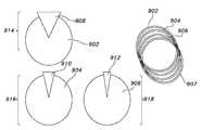
또 다른 실시예에 따르면, 부하에 대한 인쇄된 2차 회로가 제공된다. 인쇄된 2차 회로는, 비도전성 기판, 기판에 의해 지지되고 내측 직경을 정의하는 제1 인쇄된 권선, 및 기판에 의해 지지되고 내측 직경보다 작은 외측 직경을 정의하는 제2 인쇄된 권선을 포함할 수 있다. 제2 인쇄된 권선은 부하로의 접속을 위한 제1 및 제2 단부를 포함할 수 있다. 제1 및 제2 인쇄된 권선은 실질적으로 동축일 수 있으며, 기판은 제품이나 제품 용기에 부착될 수 있다. 제1 및 제2 단부는 제1 인쇄된 권선의 부분들을 가로질러 연장될 수 있다. 제1 및 제2 인쇄된 권선은 비도전성 기판의 한 측면이나 비도전성 기판의 대향하는 측면들 상에 배치될 수 있다.According to yet another embodiment, a printed secondary circuit for the load is provided. The printed secondary circuit includes a non-conductive substrate, a first printed winding supported by the substrate and defining an inner diameter, and a second printed winding supported by the substrate and defining an outer diameter smaller than the inner diameter . The second printed winding may include first and second ends for connection to a load. The first and second printed windings may be substantially coaxial and the substrate may be attached to a product or a product container. The first and second ends may extend across portions of the first printed winding. The first and second printed windings may be disposed on one side of the non-conductive substrate or on opposite sides of the non-conductive substrate.
본 발명의 이들 및 다른 이점과 특징들은 현 실시예들의 설명과 도면들에 비추어 더욱 완전하게 이해되고 인식될 것이다.These and other advantages and features of the present invention will be more fully understood and appreciated in view of the description and drawings of the present embodiments.
도 1은 유도성 제품 모니터링 시스템의 회로도이다.
도 2는 수동 제품 센서 회로를 포함하는 제품 용기의 사시도이다.
도 3은 수동 제품 센서 회로를 포함하는 분무기 어셈블리의 제품 용기의 측면도이다.
도 4는 유도성 제품 모니터링 시스템의 블록도이다.
도 5는 중량 센서 회로의 분해사시도이다.
도 6은 도 5의 중량 센서 회로의 회로도이다.
도 7은 차단막(barrier membrane)을 포함하는 중량 센서 회로의 분해사시도이다.
도 8은 수동 제품 센서 회로를 포함하는 롤형 제품(rolled product)의 사시도이다.
도 9는 롤 폼(roll form)과 수동 제품 센서 회로의 사시도이다.
도 10은 도 9의 롤 폼과 수동 제품 센서 회로의 확대 사시도이다.
도 11은 롤형 제품 트레이와 수동 제품 센서 회로의 사시도이다.
도 12는 만곡형 유도성 2차 회로(secondary)를 포함하는 롤형 제품의 사시도이다.
도 13은 가정이나 사업장 전체의 다양한 장소에 위치한 유도성 판독기 시스템의 사시도이다.
도 14는 운반용 토트(carrying tote)의 사시도이다.
도 15는 제품 보관 매트(product storage mat)의 사시도이다.
도 16은 POS 디스플레이의 사시도이다.
도 17은 유도성 판독기의 동작에 대한 플로차트이다.
도 18은 인쇄된 온도 감지 회로의 회로도이다.
도 19는 유도성 히터 시스템의 회로도이다.
도 20은 재공진기 코일을 포함하는 도 19의 유도성 히터 시스템의 회로도이다.
도 21은 저항 소자 및 바이패스 소자를 갖는 공진 회로를 포함하는 도 19의 유도성 히터 시스템의 회로도이다.
도 22는 제거가능한 절단 탭(tear tab) 상에 형성된 공진 회로의 회로도이다.
도 23은 강자성 가열 소자를 포함하는 도 22의 공진 회로도이다.
도 24는 다층 공진 회로의 측면도이다.
도 25는 직렬 공진 커패시터가 없는 도 24의 공진 회로도이다.
도 26은 제거가능한 절단 탭이 없는 도 25의 공진 회로도이다.
도 27은 인쇄된 차폐물을 갖는 도 26의 공진 회로도이다.
도 28은 온도 센서 회로를 갖는 유도성 히터 시스템의 도면이다.
도 29는 재공진기 회로를 포함하는 도 28의 유도성 히터 시스템의 도면이다.
도 30은 휴대 부하 장치를 갖는 유도성 히터 시스템의 도면이다.
도 31은 제1 및 제2 재공진기 회로를 포함하는 도 30의 유도성 히터 시스템의 도면이다.
도 32는 온도 센서 회로를 갖는 유도성 히터 시스템의 도면이다.
도 33은 재공진기 회로를 포함하는 도 32의 유도성 히터 시스템의 도면이다.
도 34는 비접촉식 전원을 포함하는 코드없는 다리미와 다림판의 도면이다.
도 35는 도 34의 비접촉식 전원의 도면이다.
도 36은 도 34의 비접촉식 전원의 동작에 대한 제1 프로세스 흐름도이다.
도 37은 도 35의 비접촉식 전원의 동작에 대한 제2 프로세스 흐름도이다.
도 38은 휴대 장치용 유도성 가열 시스템의 도면이다.
도 39는 동시에 가열재를 통전하고 배터리를 재충전하는 2차 제어 유닛을 포함하는 도 38의 유도성 가열 시스템의 도면이다.
도 40은 풋웨어 제품에 대한 가열 시스템의 도면이다.
도 41은 헤어 스트레이트너 및 컬링 아이롱용 가열 시스템의 도면이다.
도 42는 대안적 실시예에 따른 헤어 스트레이트너 및 컬링 아이롱용 가열 시스템의 도면이다.
도 43은 대안적 실시예에 따른 헤어 스트레이트너 및 컬링 아이롱용 가열 시스템의 도면이다.
도 44는 제품 정렬 시스템의 상부면도 및 측면도이다.
도 45는 도 44의 제품 정렬 시스템의 제1 정면도이다.
도 46은 도 44의 제품 정렬 시스템의 제2 정면도이다.
도 47은 POS 디스플레이 시스템의 회로도이다.
도 48은 센서 및 전자 회로를 포함하는 도 47의 POS 디스플레이 시스템의 도면이다.
도 49는 센서 회로를 포함하는 도 47의 POS 디스플레이 시스템의 도면이다.
도 50은 인쇄된 스피커 회로의 개략도이다.
도 51은 다중-코일 다중-주파수 동조 회로의 개략도이다.
도 52는 LCD 출력을 포함하는 도 51의 다중-코일 다중-주파수 동조 회로의 개략도이다.
도 53은 도 51 및 도 52의 다중-코일 다중-주파수 동조 회로용의 비접촉식 전원의 동작을 나타내는 흐름도이다.
도 54는 복수의 센서를 포함하는 POS 시스템의 사시도이다.
도 55는 인쇄된 도전성 콘택(contact)을 포함하는 제품이나 제품 용기의 사시도이다.
도 56은 도 55의 배터리 용기의 제1 도면이다.
도 57은 도 55의 배터리 용기의 제2 도면이다.
도 58은 마이크로컨트롤러-제어형 비접촉식 전원의 회로도이다.
도 59는 다중-권선 차폐형 식별 회로의 개략도이다.
도 60은 제1 장치 식별 시스템의 개략도이다.
도 61은 제2 장치 식별 시스템의 개략도이다.
도 62는 패키지의 내용물을 가열하기 위한 기판을 포함하는 도 61의 장치 식별 시스템의 개략도이다.
도 63은 인쇄된 2차 회로를 포함하는 도 61의 장치 식별 시스템의 개략도이다.
도 64는 제1 잉크 인쇄된 2차 회로의 도면이다.
도 65는 제2 잉크 인쇄된 2차 회로의 도면이다.
도 66은 가요성 탭 상에 형성된 인쇄된 공진 회로의 도면이다.
도 67은 압력 스위치를 포함하는 인쇄된 공진 회로의 도면이다.
도 68은 저항 소자와 바이패스 소자를 갖는 인쇄된 공진 회로의 회로도이다.
도 69는 다층 공진 회로의 측면도이다.
도 70은 바이패스 소자가 없는 도 67의 인쇄된 공진 회로의 도면이다.
도 71은 인쇄된 차폐물을 포함하는 도 70의 인쇄된 공진 회로의 도면이다.
도 72는 패키지 용기에 의해 지지되는 제1 다층 공진 회로의 도면이다.
도 73은 패키지 용기에 의해 지지되는 제2 다층 공진 회로의 도면이다.
도 74는 인쇄된 제품 개수 센서의 도면이다.
도 75는 무선 전력 판독기를 포함하는 주방 기구의 개략도이다.Figure 1 is a circuit diagram of an inductive product monitoring system.
2 is a perspective view of a product container including a passive product sensor circuit;
Figure 3 is a side view of a product container of an atomizer assembly including a passive product sensor circuit.
Figure 4 is a block diagram of an inductive product monitoring system.
5 is an exploded perspective view of the weight sensor circuit.
6 is a circuit diagram of the weight sensor circuit of Fig.
7 is an exploded perspective view of a weight sensor circuit including a barrier membrane.
8 is a perspective view of a rolled product including a passive product sensor circuit.
Figure 9 is a perspective view of a roll form and a passive product sensor circuit.
Figure 10 is an enlarged perspective view of the roll form and passive product sensor circuit of Figure 9;
11 is a perspective view of a rolled product tray and a passive product sensor circuit.
Figure 12 is a perspective view of a rolled product comprising a curved inductive secondary circuit.
Figure 13 is a perspective view of an inductive reader system located at various locations throughout the home or business.
14 is a perspective view of a carrying tote.
15 is a perspective view of a product storage mat.
16 is a perspective view of a POS display.
17 is a flowchart of the operation of the inductive reader.
18 is a circuit diagram of a printed temperature sensing circuit.
19 is a circuit diagram of an inductive heater system.
Figure 20 is a circuit diagram of the inductive heater system of Figure 19 including a re-resonator coil.
Figure 21 is a circuit diagram of the inductive heater system of Figure 19 including a resonant circuit with resistive and bypass elements.
22 is a circuit diagram of a resonant circuit formed on a removable tear tab;
Fig. 23 is a resonant circuit diagram of Fig. 22 including a ferromagnetic heating element. Fig.
24 is a side view of the multilayer resonance circuit.
Fig. 25 is a resonant circuit diagram of Fig. 24 without a series resonant capacitor. Fig.
Fig. 26 is a resonant circuit diagram of Fig. 25 without a removable cut tab. Fig.
Fig. 27 is a resonant circuit diagram of Fig. 26 with a printed shield. Fig.
28 is a diagram of an inductive heater system having a temperature sensor circuit.
Figure 29 is a diagram of the inductive heater system of Figure 28 including a re-resonator circuit.
30 is a diagram of an inductive heater system having a portable load device.
31 is a diagram of the inductive heater system of FIG. 30 including first and second resonator circuits.
32 is a diagram of an inductive heater system having a temperature sensor circuit.
Figure 33 is a diagram of the inductive heater system of Figure 32 including a re-resonator circuit.
34 is a view of a cordless iron and ironing board including a non-contact power source.
Fig. 35 is a view of the contactless power supply of Fig. 34; Fig.
Fig. 36 is a first process flow chart for the operation of the contactless power supply of Fig. 34;
37 is a second process flow chart for the operation of the contactless power supply of Fig.
38 is a diagram of an inductive heating system for a portable device.
39 is a view of the inductive heating system of Fig. 38 including a secondary control unit that simultaneously energizes the heating material and recharges the battery.
40 is a view of a heating system for a footwear product.
41 is a view of a heating system for hair straightener and curling iron.
42 is a view of a heating system for hair straightener and curling iron according to an alternative embodiment.
43 is a view of a heating system for hair straightener and curling iron according to an alternative embodiment.
Figure 44 is a top view and side view of the product alignment system.
45 is a first front view of the product alignment system of FIG. 44;
46 is a second front view of the product alignment system of FIG.
47 is a circuit diagram of a POS display system.
Figure 48 is a diagram of the POS display system of Figure 47, including a sensor and electronic circuitry.
Figure 49 is a diagram of the POS display system of Figure 47, including sensor circuitry.
50 is a schematic view of a printed speaker circuit;
51 is a schematic diagram of a multi-coil multi-frequency tuning circuit.
52 is a schematic diagram of the multi-coil multi-frequency tuning circuit of FIG. 51 including an LCD output.
Figure 53 is a flow diagram illustrating the operation of the contactless power supply for the multi-coil multi-frequency tuning circuit of Figures 51 and 52;
54 is a perspective view of a POS system including a plurality of sensors.
55 is a perspective view of a product or product container including a printed conductive contact.
56 is a first view of the battery container of FIG. 55;
FIG. 57 is a second view of the battery container of FIG. 55; FIG.
58 is a circuit diagram of a microcontroller-controlled non-contact power source.
59 is a schematic diagram of a multi-winding shielded identification circuit.
60 is a schematic diagram of a first device identification system.
61 is a schematic diagram of a second device identification system.
62 is a schematic view of the apparatus identification system of FIG. 61 including a substrate for heating the contents of the package.
63 is a schematic diagram of the apparatus identification system of FIG. 61 including a printed secondary circuit.
64 is a diagram of a first ink printed secondary circuit.
65 is a diagram of a second ink printed secondary circuit.
66 is a view of a printed resonant circuit formed on a flexible tab.
67 is a view of a printed resonant circuit including a pressure switch.
68 is a circuit diagram of a printed resonance circuit having a resistive element and a bypass element.
69 is a side view of the multilayer resonance circuit.
Figure 70 is a diagram of the printed resonant circuit of Figure 67 without a bypass element.
71 is a view of the printed resonant circuit of Fig. 70 including the printed shield.
72 is a view of a first multi-layer resonant circuit supported by a package container;
73 is a view of a second multilayer resonance circuit supported by a package container;
74 is a view of a printed product number sensor.
75 is a schematic diagram of a kitchen appliance including a wireless power reader.
본 발명의 실시예들은 POS 및 기타 장소에서 제품의 식별, 전원 공급 및 제어와 관련된 무선 전력 시스템 및 방법을 제공한다.Embodiments of the present invention provide a wireless power system and method associated with product identification, power supply and control at POS and other locations.
I.제품모니터링 시스템I.ProductMonitoringSystem
본 발명의 제1 양태에서, 제품 레벨을 모니터링하기 위한 시스템이 제공된다. 이 시스템은, 유도성 판독기와, 수동 식별 회로 및 제품량 센서 회로를 갖는 제품 용기를 포함할 수 있다. 유도성 판독기는, 각각, 수동 식별 회로 및 제품량 센서 회로의 반사 임피던스(reflected impedance)에 기초하여 제품과 제품량을 식별하도록 동작할 수 있다.In a first aspect of the present invention, a system for monitoring product level is provided. The system may include an inductive reader, a product container having a manual identification circuit and a product quantity sensor circuit. The inductive reader may be operable to identify product and product quantities, respectively, based on the reflected impedance of the passive identification circuit and the product quantity sensor circuit.
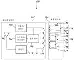
제1 실시예에 따르면, 액체 제품 레벨을 모니터링하기 위한 시스템이 도 1 내지 도 5에 나타나 있으며, 일반적으로 100으로 지정되어 있다. 이 시스템은 유도성 판독기(102)와 제품 용기(104)를 포함한다. 유도성 판독기(102)는 1차 코일(106), 구동기(108), 전류 센서(110), 마이크로컨트롤러(112), 및 송신기(114)를 포함할 수 있다. 구동기(108)는 1차 코일(106)에 전기적으로 접속되어 동작 주파수 범위에 걸쳐 1차 코일(106)을 구동할 수 있다. 마이크컨트롤러(112)는 구동기(108)에 전기적으로 접속되어 구동기 출력, 및 그에 따라 동작 주파수를 제어할 수 있다. 전류 센서(110), 선택사항으로서 홀 효과 전류 센서는, 1차 코일(106)의 전류에 비례하는 전기 출력을 생성한다. 사용시, 구동기(108)는 근처의 유도성 2차 회로로부터의 반사 임피던스를 모니터링하면서 미리 결정된 범위의 주파수를 스위핑(sweep through)할 수 있다. 1차 코일(106)의 전류가 전류 센서(110)에 의해 측정되는 임계치, 국지적 최대값들, 또는 기타의 기준을 달성하면, 마이크로컨트롤러(112)는 대응하는 동작 주파수 또는 주파수들을 비휘발성 메모리에 기록할 수 있다. 이하에서 설명되는 바와 같이, 이 동작 주파수 또는 주파수들은 고유 유도성 식별 프로파일 및/또는 잔여 액체의 측정치에 대응할 수 있다. 메모리에 저장된 룩업 테이블을 참조하면, 마이크로컨트롤러(112)는 액체와 그 잔량을 식별할 수 있다.According to a first embodiment, a system for monitoring liquid product levels is shown in Figures 1 to 5 and is generally designated as 100. [ The system includes an inductive reader (102) and a product container (104). The
도 1에 도시된 바와 같이, 제품 용기(104)는 수동 제품 식별 회로(116)와 수동 제품 센서 회로(118)를 포함한다. 수동 제품 식별 회로(114)는 하나 이상의 격리된 공진 회로(120, 122)를 포함할 수 있다. 인덕터(124) 및 커패시터(126)를 갖는 LC 회로로서 도시된 각각의 격리된 공진 회로는 제품 용기(104)의 유도성 식별 프로파일에 기여한다. 즉, 격리된 공진 회로(120, 122)는 근처의 1차 코일(106)의 시변동 전류에 응답하여 반사 임피던스를 생성할 수 있다. 유도성 판독기(102)는, 그리고 특히, 전류 센서(110)는 반사 임피던스를 모니터링하여 격리된 공진 회로(120, 122)에 대응하는 하나 이상의 고유 공진 주파수를 식별할 수 있다. 각각의 공진 주파수는 동조 인덕턴스, 동조 커패시턴스, 또는 양쪽 모두의 결과일 수 있다. 마이크로컨트롤러(112)는, 수동 제품 식별 회로(116)의 검출된 공진 주파수를 메모리에 저장된 룩업 테이블과 비교함으로써, 용기(104), 및 그에 따라 그 내용물을 식별할 수 있다. 공진 회로(118, 120)의 공진 주파수는 또한, 이하의 파트 VII에서 더 상세히 설명되는 바와 같이, 다수의 고유 식별 코드의 생성을 허용할 수 있다.As shown in FIG. 1, the
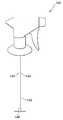
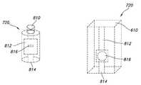
수동 제품 센서 회로(118)는 2차 코일(128), 가변 저항(130), 및 직렬 커패시터(132)를 포함할 수 있다. 예시된 실시예에서, 수동 제품 센서 회로(118)의 저항은 잔여 액체의 부피의 함수로서 변한다. 다른 실시예들에서, 인덕턴스, 커패시턴스, 또는 양쪽 모두가 변할 수 있다. 도 2에 도시된 바와 같이, 예를 들어, 제품 용기(104)는 베이스(134), 상방으로 연장되며 주변부 또는 개구(138)에서 끝나는 적어도 하나의 측벽(136), 유도성 권선(140), 및 유도성 권선(140)의 대향 단부들에 전기적으로 접속된 제1 및 제2 도전체(142, 144)를 더 포함할 수 있다. 제1 및 제2 도전체(142, 144)는 실질적으로 서로 평행하며, 이격되어 있는 관계로 대체로 수직으로 세워져 있다. 저항성 또는 용량성 소자(146)는 도전체들(142, 144)을 가로질러 접속될 수 있다. 사용 동안에, 제품 용기(104)는 상위 레벨(149)을 정의하는 도전성 유체(148)를 포함할 수 있다. 유체(148)는 액체, 겔, 또는 기타 임의의 충분히 도전성인 재료의 형태일 수 있다. 예를 들어, 유체는 적어도 부분적으로 도전성이 되게 하는 충분한 전해질(electrolyte)을 포함할 수 있다.The passive
유도성 권선(140), 도전체(142, 144) 및 저항성 또는 용량성 소자(146)는, 델라웨어주 윌밍턴시 Dupont사의 Mylar® 필름과 같은 가요성의 방수재로 완전히 또는 부분적으로 코팅될 수 있다. 유도성 권선(140)은 제품 용기 베이스(134)에 따르는 실질적으로 평면형 구성으로 배향될 수 있다. 선택사항으로서, 유도성 권선(140)은 그 제조 동안에 제품 용기(104)와 일체로 형성될 수 있다. 한 실시예에서, 수동 제품 센서 회로(118)는, 도 2에 개괄적으로 도시된 바와 같이, 제품 용기(104)가 형성된 후에 제품 용기(104) 내에 삽입될 수 있다. 예를 들어, 수동 제품 센서 회로(118)는 제품의 구매시 사용자에 의해 제품 용기(104) 내에 삽입되거나, 및/또는 수동 제품 센서 회로(118)는 제품 용기(104)의 분리가능한 부분과 함께 일체화될 수 있다. 도 3에도 도시된 바와 같이, 수동 제품 센서 회로(118)는 분무기 병을 위한 분무기 어셈블리(150)의 일부를 형성할 수 있다. 이 실시예에서, 도전체(142, 144)는 공급 튜브(152)의 대향 측면들 상에 위치한다. 인쇄된 후에 추가의 잉크나 코팅을 이용하여 절연될 수 있는 유도성 권선(140)과 저항성 또는 용량성 소자(146)는 공급 튜브(150)의 베이스(146)에 위치할 수 있다. 도전성 유체의 레벨(148)이 감소함에 따라, 수동 제품 센서 회로(118)의 임피던스는 변할 것이다. 수동 제품 센서 회로(118)의 임피던스 변화는 유도성 판독기(102)의 1차 코일(106)에서 측정되는 전류에 영향을 미칠 것이다. 그 다음, 마이크로프로세서(112)는, 제품 잔량을 판정하기 위해 주어진 제품에 대한 1차 코일(106)의 반사 임피던스를 평가할 수 있다. 예를 들어, 마이크로프로세서(112)는 수동 제품 식별 회로(116)의 피드백에 대해 반사 임피던스를 참조하여 상대적 반사 임피던스를 설정한다. 상대적 반사 임피던스를 이용하여, 마이크로프로세서(112)는 그 특정한 제품 타입에 대한 반사 임피던스 테이블에 액세스할 수 있다. 마이크로프로세서(112)는 반사 임피던스 테이블을 이용하여 마이크로프로세서(112)에 의해 기록된 반사 임피던스에 대응하는 제품량을 판정할 수 있다. 유도성 판독기(102)는 중앙 허브(168)에 제품량과 제품 타입을 송신하기 위해 저전력 송신기(114)와 안테나(115)를 포함한다. 제품 타입과 반사 임피던스 데이터가 룩업 테이블에 포함되어 있지 않으면, 중앙 허브(168)로부터 액세스된 셋업 스크린 그래픽 유저 인터페이스(GUI)를 통해 유도성 판독기(102)에 새로운 데이터가 업로드될 수 있다. 유도성 판독기(102)는 또한, 다른 유도성 판독기들로부터 유도성 판독기(102)를 구분하는 미리 결정된 식별자를 포함할 수 있다. 이 식별자는 제품 정보와 함께 중앙 허브(168)에 송신될 수 있다. 이들 및 다른 데이터 송신은 하드-와이어드 네트워크, 무선 기술, 또는 기타의 적절한 통신 시스템을 통해 달성될 수 있다.The inductive winding 140, the
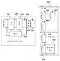
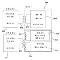
도 4를 참조하면, 중앙 허브(168)는 제품량, 제품 타입, 센서 타입, 참조 데이터, 및 고유의 유도성 판독기 식별자에 관한 정보를 송신기(114)로부터 수신하는 수신기(170)를 포함할 수 있다. 수신기(170)는, 제품 및 판독기 정보를 네트워크 서버(174)에 송신하는 저전력 송신기(172)에 접속될 수 있다. 중앙 허브(168)는, 고유의 사용자 프로파일 식별자들을 전체 시스템에 또는 개개의 유도성 판독기(102)에 링크시키기 위해 셋업 스크린을 통해 프로그램될 수 있다. 도 4에도 역시 도시된 바와 같이, 네트워크 서버(174)는 수신기(176), 데이터 애플리케이션(178) 및 데이터 저장장치(180)를 포함한다. 수신기(176)는 송신기(172)로부터의 제품 및 사용자 정보를 수신한다. 이 정보는 각각의 고유 사용자 프로파일에 대한 사용자 계정을 포함할 수 있는 데이터 저장 장치(180)에 송신된다. 데이터 애플리케이션(178)은 다양한 동작이 취해져야 하는지를 판정하기 위해 제품량을 처리하는 소프트웨어를 포함할 수 있다. 예를 들어, 쇼핑 목록에 제품이 추가되어야 하는지를 판정하기 위해 제품량, 소비 속도, 및 다가올 상점 방문 타이밍이 이용될 수 있다. 만일 제품이 쇼핑 목록에 추가되어야 한다면, 제품량이 적다는 것을 나타내기 위해 사용자에게 e-메일이나 문자 메시지 경고가 전송되거나, 제품이 디지털 쇼핑 목록에 자동으로 추가되거나, 제품이 자동으로 재주문될 수 있다. 만일 제품이 쇼핑 목록에 추가될 필요가 없다면, 네트워크 서버(174)는 모니터링 중인 모든 제품들의 현재 레벨로 데이터 저장장치(180)를 계속 업데이트할 수 있다. 이것은 또한, 제품 사용법, 예산, 알뜰 쇼핑, 식사 및 칼로리 섭취량 계획, 제품 서비스 계획, 및 처방전 준수에 관한 정보를 포함할 수 있다. 이 정보는 웹페이지나, 애플리케이션에 적합한 기타 임의의 정보 시스템을 통해 검색될 수 있다.4, the
전술된 네트워크는 저전력 네트워크일 수 있다. 저전력 네트워크의 예는 Fells 등에 의해 2009년 10월 2일 출원되고, 이제는 미국 특허 제 ______호인, "Power System"이란 명칭의 미국 출원 제12/572,296호에 개시되어 있으며, 그 전체를 참조용으로 인용한다. 또한, 기계적 정렬 시스템 및 자기 정렬 시스템을 포함하지만 이들만으로 한정되지 않는 애플리케이션에 적합한 임의의 정렬 장치를 통해, 2차 코일은 1차 코일(106)과 정렬될 수 있다. 적절한 정렬 시스템의 예는 Baarman 등에 의해 2009년 2월 20일 출원되고, 이제는 미국 특허 제 ______호인, "Magnetic Positioning for Inductive Coupling"이란 명칭의 미국 출원 제12/390,178호에 개시되어 있으며, 그 전체를 참조용으로 인용한다.The aforementioned network may be a low power network. An example of a low-power network is disclosed in U. S. Patent Application No. 12 / 572,296, entitled " Power System, " filed October 2, 2009, now U.S. Patent No. ______________________________________ I quote. In addition, the secondary coil can be aligned with the
유도성 판독기(102)는 제품(104)을 주기적으로 "판독"하기 때문에, 예를 들어, 제품이 대체될 때, 매우 저전력의 센스 회로가 제품(104)을 판독하기 위해 핑(ping)이나 스윕을 트리거한 다음 허브(168)를 업데이트하고, 그 직후 셧다운될 수 있다. 진폭 변조의 첨가는 한개 비트가 기준이 되도록 허용하는 한편 잔여 비트들의 진폭의 변경은 추가의 조합을 허용한다. 반환값의 적절하고 간단한 이해를 보장하기 위해 비트 위치들과 센서 분류 및 기준 주파수 정보와 함께 센서 및 식별자들에 대한 범위가 설정될 수 있다. 복수의 주파수들을 비트들로서 이용하면, 공진 주파수는 제1 2진값을 나타내기 위해 이용될 수 있는 한편 공진 주파수의 부재는 제2 2진 값을 나타낼 수 있다. 이것은 이하의 파트 VII에 개시된 가능성들의 매우 큰 시퀀스를 허용한다. 이 식별 방법은, 코일보다 많은 비트 위치나 주파수를 이용하여 더 많은 가능한 조합을 얻기 위해 더 적은 코일을 이용하여 확장될 수 있다.Because the
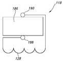
또 다른 실시예에 따라 구성된 제품 모니터링 시스템이 도 5 내지 도 7에 나타나 있으며 개괄적으로 182로 지정되어 있다. 제품 모니터링 시스템(182)은 전술된 제품 레벨 센서(100)와 유사하며, 제품의 중량의 함수로서 임피던스가 변하는 수동 제품 센서 회로(184)가 추가되었다.A product monitoring system constructed in accordance with yet another embodiment is shown in FIGS. 5-7 and is generally designated 182. The
더 구체적으로는, 제품 중량 센서(184)는 유도성 판독기(102)의 1차 코일(106)과 정렬된 나선형 평면 2차 코일(128)을 포함한다. 전기적으로 도전성인 압축가능한 패드(186)가 2차 코일(128)과 병렬로 접속된다. 패드(186)는, 거품 제재(foam)와 같은, 임의의 가요성의 전기 도전성 재료로 만들어질 수 있다. 제품 레벨 센서 회로(118)는, 패드(186)의 한 측면에 위치한 제1 전기 콘택(188)과 패드(186)의 다른 측면에 위치한 제2 전기 콘택(190)을 포함할 수 있다. 제품 중량 센서(184)는 그 제조 동안에 제품 용기(104)와 일체로 형성될 수 있다. 대안으로서, 제품 중량 센서(184)는 제품 용기(104)가 형성된 후에 제품 용기(104) 내에 삽입될 수 있다. 추가로 선택사항으로서, 도 5에 도시된 바와 같이, 제품 중량 센서(184)는, 제품 용기(104)가 제품 중량 센서(184)의 상부에 위치하도록, 제품 용기(104)의 외부에 위치할 수 있다. 도 7에 도시된 바와 같이, 제품 모니터링 시스템(100)은, 제품이 제품 중량 센서(184)와 직접 접촉하는 것을 방지하는 차단막(barrier membrane)(192)을 포함할 수 있다. 제품 중량 센서(184)는 또한, 어셈블리 커버(194)를 포함할 수 있다.More specifically, the
제품 용기(104)가 비어 있을 때, 제품 레벨 센서 회로(118)의 임피던스는 초기값에 있다. 제품(148)이 제품 용기(104)에 추가됨에 따라, 패드(186)의 상부면 상의 총 중량은 증가한다. 패드(186)가 추가된 제품(148)의 중량으로 구부러짐에 따라, 2개의 전기 콘택(188, 190)은 서로 접근한다. 콘택(188, 190)이 서로 가깝게 이동함에 따라, 제품 레벨 센서 회로(118)의 임피던스는 변한다. 전술된 바와 같이, 제품 레벨 센서 회로(118)의 임피던스는 1차 코일(106)의 전류를 측정함으로써 모니터링될 수 있다. 제품량, 제품 타입, 및 고유 유도성 판독기 식별자는, 실질적으로 전술된 바와 같이, 중앙 허브(168)에, 그리고 네트워크 서버(174)에 송신될 수 있다. 이 실시예의 변형에서, 제품 레벨 센서 회로(118)는 추가된 제품(148)의 중량으로 차단막이 구부러짐에 따라 임피던스가 변하는 도전성 멤브레인을 포함할 수 있다. 변화된 임피던스는 실질적으로 전술된 바와 같은 방식으로 줄어든 액체양과 상관될 수 있다.When the
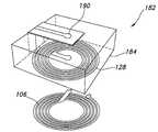
또 다른 실시예에 따라 구성된 제품 모니터링 시스템이 도 8 내지 도 12에 나타나 있으며 개괄적으로 200으로 지정되어 있다. 제품 모니터링 시스템(200)은 전술된 제품 레벨 센서(100)와 유사하며, 시트재의 롤(204)로부터 시트들이 제거됨에 따라 임피던스가 변하는 수동 제품 센서 회로(202)가 추가되었다.A product monitoring system constructed in accordance with yet another embodiment is shown in Figures 8-12 and is generally designated as 200. [ The product monitoring system 200 is similar to the
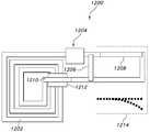
제품 롤(204)은 롤형 제품(206), 롤 폼(roll foam)(208), 및 적어도 하나의 천공(perforation)(210)을 포함할 수 있다. 롤 폼(208)은 판지(paperboard)나 기타의 적절한 재료로 형성될 수 있다. 천공(210)은, 더 작은 롤들로의 제품 롤(204)의 분리를 허용한다. 도 9 및 도 10에 도시된 바와 같이, 롤형 제품 센서(202)는 롤 폼(208)에 의해 지지되며, 실질적으로 평행한 배향으로 배열되고 롬 폼(208)의 길이를 따라 연장되는 제1 및 제2 도전체들(212)을 포함한다. 적어도 하나의 저항성 또는 용량성 소자(214)는 제품 롤(204)의 각각의 천공된 구획에서 도전체들(212)을 접속할 수 있다. 제품 롤(204)이 이용되고 천공된 구획들이 제거되면, 그 천공된 구획에 대해 도전체들(212)을 접속하는 저항성 또는 용량성 소자(214)도 역시 회로로부터 제거된다. 저항성 또는 용량성 소자(214)의 제거는 유도성 2차 회로(128)의 임피던스가 변하게 한다. 전술된 실시예에 관하여 설명된 바와 같이, 유도성 2차 회로(128)의 임피던스는 제품 수량을 판정하기 위해 유도성 판독기(102)에 의해 모니터링될 수 있다. 제품량, 그리고 선택사항으로서 제품 타입 및 고유 유도성 판독기 식별자는, 실질적으로 전술된 바와 같이, 중앙 허브(168)에, 그리고 네트워크 서버(174)에 송신될 수 있다.The
이제 도 11을 참조하면, 제품 모니터링 시스템(200)은 또한 롤형 제품 트레이(216)를 포함할 수 있다. 롤형 제품 트레이(216)는 제품 롤(204)을 수용하도록 크기조정된 6개의 소켓(218)을 포함할 수 있다. 각각의 소켓(218)은, 롤 폼(208)이 대응하는 소켓(218) 내에 수용될 때 제1 및 제2 도전체들(212)로의 전기 접속을 위한 제1 및 제2 리드(lead)(220)를 포함할 수 있다. 제1 및 제2 리드(220)는 실질적으로 평면인 2차 코일(222)에 접속될 수 있다. 2차 코일(222)은 실질적으로 전술된 바와 같이 1차 코일(224)과 정렬될 수 있다.Referring now to FIG. 11, the product monitoring system 200 may also include a rolled
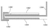
이 실시예의 변형이 도 12에 도시되어 있다. 이 변형에서, 수동 제품 센서 회로(202)는 제품 내에 통합되거나 제품(206)의 한 면에 위치하는 도전체들(212)을 포함할 수 있다. 적어도 하나의 저항성 또는 용량성 소자(214)는 선택사항으로서 제품(206)의 각각의 개별 시트 상에 도전체들(212)을 접속할 수 있다. 만일 제품이 개별 시트들을 분리하기 위해 축 방향으로 천공된다면, 제품의 시트마다 미리 결정된 양의 저항성 또는 용량성 소자(214)가 이용될 수 있다. 만일 제품이 천공되지 않으면, 소정 길이의 제품에 대해 미리 결정된 양의 저항성 또는 용량성 소자(214)가 이용될 수 있다. 이 구성에서, 제품이 이용될 때, 저항성 또는 용량성 소자(214)가 회로(202)로부터 제거될 수 있다. 저항성 또는 용량성 소자(214)가 제거되면, 회로(202)의 임피던스가 변할 수 있다. 도 12에도 역시 도시된 바와 같이, 1차 코일(224)과 2차 코일(222)은 만곡형일 수도 있으며, 롤 폼(208)의 표면의 곡률과 실질적으로 정합할 수 있다. 이 구성은 롤 폼(208)의 내측 또는 외측 표면 상에서의 2차 코일(222)의 추가의 선택사항적 배치와 롤 홀딩 랙의 내측이나 외측 표면 상에서의 1차 코일(224)의 배치를 허용할 수 있다. 이 구성에 따른 제품 롤(204)은 롤형 제품 트레이(216)에 접속될 수도 있으며 제품량은 실질적으로 전술된 바와 같이 모니터링될 수 있다. 이런 방식으로, 도 8 및 도 12의 실시예들에 따른 롤형 제품 모니터링 시스템은 도 11의 롤형 제품 트레이(216) 상에 동시에 고정될 수 있다. 선택사항으로서, 도 8 및 도 12의 실시예들은, 스택 내의 롤의 개수와 벌크 패키지 내의 스택들의 개수가 모니터링될 수 있도록 결합될 수 있다.A modification of this embodiment is shown in Fig. In this variation, the passive
II.유도성 판독기 시스템II.Inductive reader system
본 발명의 제2 양태에서는, 가정, 사업장, 또는 기타의 장소 전반의 다양한 장소에 국지적 유도성 판독기군(localized clusters of inductive readers)이 배치된다. 유도성 판독기는 제품의 신원과 제품 잔량 양쪽 모두를 판정하도록 동작한다. 일부 응용에서, 유도성 판독기들은 주어진 제품의 이용 이력에 기초하여 사용자에게 정보를 제공할 수 있다. 예를 들어, 유도성 판독기들은 영양 소모 데이터를 제공하고 식료품 저장소나 기타 장소의 잔여 식품양에 기초하여 쇼핑 목록을 생성할 수 있다.In a second aspect of the invention, localized clusters of inductive readers are located at various locations throughout the home, workplace, or other location. The inductive reader operates to determine both the identity of the product and the product remaining. In some applications, inductive readers may provide information to a user based on a history of use of a given product. For example, inductive readers can provide nutrition consumption data and create shopping lists based on the amount of food left in the grocery store or other places.
한 실시예에 따른 유도성 판독기 시스템이 도 13 내지 도 15에 나타나 있으며 개괄적으로 300으로 지정되어 있다. 시스템(300)은, 독립적으로 동작하며 그들의 제품 식별, 제품량, 및 고유 유도성 판독기 식별자를 중앙 허브(302)에 송신하는 국지화된 유도성 판독기군을 포함한다. 중앙 허브(302)는 누적된 제품 및 사용자 정보를 Wi-Fi 광대역 라우터 및 모뎀(306)과 같은 임의의 적절한 장치를 통해 네트워크 서버(304)에 송신할 수 있다.An inductive reader system in accordance with one embodiment is shown in Figures 13-15 and is generally designated as 300. < RTI ID = 0.0 >
유도성 판독기는 가정, 사업장 또는 기타 장소 전반의 다양한 장소에 있을 수 있다. 판독기는, 다양한 제품(318)을 판독하기 위해, 냉장고 저장부 표면(308), 캐비넷 저장부 표면(310), 샤워 저장부 표면(312), 세탁실 저장부 표면(314), 토트(tote, 316)에 위치할 수 있다. 각각의 판독기는 중앙 허브(302)용 셋업 GUI에서 고유 프로파일 식별자에 의해 표현될 수 있다. 도 15에 도시된 바와 같이, 휴대형 보관 매트(320)는 다양한 장소에 임시로 배치될 수 있다. 보관 매트(320)와 기타 임의의 유도성 판독기는, 적어도 하나의 1차 코일(106)이 각 제품의 양을 식별하고 판정하기 위해 각 제품 패키지와 충분히 정렬되도록, 복수의 1차 코일(106)을 포함할 수 있다. 제품 패키지 내의 2차 코일(128)은 실질적으로 전술된 바와 같이 정렬 시스템을 이용하여 1차 코일(106)과 정렬될 수 있다. 또한 전술된 바와 같이, 유도성 판독기들은 제품을 식별하고, 제품량을 판정하며, 유도성 판독기 식별자와 함께 이 정보를 중앙 허브(302)에 송신할 수 있다. 중앙 허브(302)는 제품과 사용자 정보를 네트워크 서버(304)에 송신하고, 네트워크 서버는 이 정보를 광대역 인터넷 접속이나 전자 데이터를 전송하기 위한 기타 임의의 통신 아키텍쳐를 통해 컴퓨터(322), 핸드헬드 전자 장치(324), 또는 기타의 네트워크 서버에 송신할 수 있다.Inductive readers can be at various locations throughout the home, business or other places. The reader includes a
국지화된 유도성 판독기군은 또한, 식료품 저장 위치 및/또는 요리 기구를 모니터링하여 가정에서 소비되는 식품에 관련된 칼로리 섭취량이나 기타의 영양소 데이터를 판정하는 데 이용될 수 있다. 이 구성에서, 위의 파트 I에서 언급한 데이터 애플리케이션(178)은 소정 기간에 걸쳐 소비된 총 칼로리, 소정 기간에 걸쳐 소비된 평균 칼로리, 및/또는 기타의 유용한 영양 정보를 계산하기 위해 제품량을 처리하는 소프트웨어를 포함할 수 있다. 데이터 애플리케이션은 또한, 예를 들어 다양한 다른 개인 건강 지표 및 가정 안전을 모니터링할 수 있다.A localized group of inductive readers may also be used to monitor the food storage location and / or the cooking utensil to determine calorie intake or other nutrient data related to food consumed in the home. In this configuration, the
도 16에 도시된 바와 같은 또 다른 변형에서, 식료품점, 백화점, 또는 기타의 유사한 사업장의 디스플레이 유닛(330)에는 유도성 판독기(102)가 장착될 수 있다. 디스플레이 유닛 상에 위치한 제품의 수에 관해 유도성 판독기(102)에 의해 수집된 데이터는 재고를 추적하고, 능동적 디스플레이 표지판을 구동하거나 상점의 구매부에 대해 재주문을 트리거링할 수 있다. 선택사항으로서, 디스플레이 유닛(330)은 선반 및 기타의 종래의 디스플레이면(332)을 포함할 수 있으며, 여기서, 유도성 판독기(102)의 1차 코일(들)(334)은, 예를 들어, 디스플레이 선반(332) 내의 디스플레이면(332)의 표면에 인접하게 위치한다. 도 15에 나타낸 바와 같이, 디스플레이 유닛(330)은, 디스플레이 유닛(330)의 표면 아래에서 수직이나 수평으로 연장되는 하나의 타원형 1차 권선(334)을 포함하거나, 선반 유닛(330)의 표면 아래에 위치한 복수의 1차 코일(334)을 포함할 수 있다. 선반 유닛은 자체로 전력을 유도식으로 수신하거나, 종래의 메인 접속을 통해 전력을 수신할 수 있다.16, the display unit 330 of a grocery store, a department store, or other similar workplace may be equipped with an
또 다른 실시예에서, POS 디스플레이(332)를 위한 제품 모니터링 시스템은, 유도성 판독기(102), 및 각각이 선택사항으로서는 POS 디스플레이에 의해 지지되는 복수의 제품 용기(104)를 포함한다. 유도성 판독기(102)는 1차 탱크 회로를 포함할 수 있으며, 제품 용기(104) 각각은 임피던스 소자를 포함할 수 있다. 유도성 판독기(102)는, (1) 임피던스 소자를 포함하는 제품 용기를 POS 디스플레이에 추가하는 것, 및/또는 (2) POS 디스플레이로부터 복수의 제품 용기들 중 적어도 하나를 제거하는 것에 응답하여 1차 탱크 회로에서의 전력 특성의 변화를 검출하도록 구성될 수 있다. 전력 특성은 전압, 전류 및 위상 중 하나를 포함할 수 있다. 복수의 제품 용기(104)는 누적 임피던스를 정의할 수 있고, 유도성 판독기(102)는 1차 탱크 회로에서의 전력 특성의 변화에 대응하는 반사 누적 임피던스의 변화를 검출하도록 구성될 수 있다. 예를 들어, 유도성 판독기(102)는, (선택사항으로서는 다른 제품 용기들 중에서) 제품 용기(104)를 유도성 판독기(102) 부근에 배치한 것에 응답한 누적 반사 임피던스의 증가를 검출할 수 있다. 유도성 판독기(102)는 또한, 유도성 판독기(102) 부근으로부터 제품 용기(104)를 제거한 것에 응답한 누적 반사 임피던스의 감소를 검출할 수 있다. 임피던스 소자는, 예를 들어, 용량성 소자, 유도성 소자 또는 저항성 소자를 포함할 수 있다. 선택사항으로서, 임피던스 소자는, 2차 회로(116), 예를 들어, 2차 코일과 직렬 커패시터를 갖는 수동 식별 회로(116)의 일부를 형성할 수 있다. 임피던스는 복수의 제품 용기(104) 각각에 대해 동일하거나, 서로에 관하여 상이할 수 있다. POS 디스플레이는 선반 유닛이나 벽면 랙(wall rack)(332) 또는 복수의 제품 용기를 지지하는 기타의 장치를 포함할 수 있다. POS 디스플레이는 깊이, 폭, 및/또는 높이를 정의할 수 있으며, 1차 탱크 회로는, 하나 이상의 행이나 열을 따라 제품들을 동시에 모니터링하기 위해 실질적으로 POS 디스플레이의 각각의 깊이, 폭 및/또는 높이를 따라 연장되는 1차 코일(334)을 포함할 수 있다. 유도성 판독기(102)는 누적 반사 임피던스에 기초한 정보를 중앙 허브(168)에 송신하도록 구성될 수 있다. 중앙 허브(168)는, 제품 용기(104)가 POS 디스플레이에 추가되거나 이로부터 제거될 때 제품 재고 레벨 이력을 유지하도록 구성된 메모리를 포함할 수 있다. 제품 모니터링 시스템은 또한, 이하의 파트 V에 더욱 상세히 개시된 바와 같이 1차 코일(624) 및 연관된 전원(632)과 연계하여 사용될 수 있다. 예를 들어, 제품 모니터링 시스템은 POS 디스플레이(332) 상의 제품 재고 레벨을 모니터링하기 위한 유도성 판독기(102)와 POS 디스플레이(332) 상의 실질적으로 선두 제품들에만 전력을 제공하기 위한 비접촉식 전원(624)을 포함할 수 있다.In yet another embodiment, a product monitoring system for a
전술된 제품 모니터링 시스템은 광범위한 응용에 걸쳐 이용될 수 있다. 예를 들어, 중앙 허브(168), 네트워크 서버(174), 또는 유도성 판독기(102)망과 통신하는 기타의 데이터 로거(data logger)는 모니터링 기간 전체에 걸쳐, 예를 들어, 24 시간 모니터링 기간 동안, POS 재고 레벨을 기록할 수 있다. 기록된 POS 재고 레벨은, 특히 POS 재고 레벨이 미리 결정된 양 아래로 떨어지면 제품 재고보충(re-stocking)을 트리거하기 위해 이용될 수 있다. 기록된 POS 재고 레벨은 또한, 원하는 수의 제품 용기보다 적은 용기가 POS 디스플레이 중에 있는 기간을 추적하는 데 이용될 수 있다. 이 정보는, 예를 들어 그 제품이 상점 선반에 계속 보충되어야 하는지를 알고자 하는 제조자에게 제공될 수 있다. 기록된 POS 재고 레벨은 또한, 제품의 만료일에 따라 제품의 판매를 추적하는 데 이용될 수 있으며, 만료일에 도달했거나 그 부근에 있는 제품의 제거나 할인을 트리거할 수 있다. 기록된 POS 재고 레벨은, 예를 들어, 제품 식별자, 유도성 판독기 식별자, 만료일 및/또는 선반 유닛에 의해 카테고리화된 제품량 레벨을 포함할 수 있다. POS용 제품 용기에 관하여 전술되었지만, 제품 모니터링 시스템은 또한, 예를 들어, 창고 재고, 조립 공장, 소포 처리를 포함한 다른 응용에도 이용될 수 있으며, 용기를 제외한 제품에도 적합할 수 있다.The product monitoring system described above can be used across a wide range of applications. Other data loggers in communication with the
추가의 실시예들은, 체크-아웃 단말기, 세탁 기구, 스토브 및 마이크로웨이브 기구와 조합한 유도성 판독기(102)를 포함한다. 예를 들어, 체크-아웃 단말기는, 선택사항으로서 종래의 바코드 판독기를 대체하거나 증강시키기 위해 유도성 단말기(102)를 포함할 수 있다. 유도성 판독기(102)는, 하나 이상의 연관된 공진 회로(120)의 공진 주파수나 반사 임피던스에 기초하여 제품을 식별하기 위해 복수의 주파수에서 동작가능한 하나 이상의 1차 코일(106)을 포함할 수 있다. 그러면, 유도성 판독기는 복수의 판독기 회로 동작 주파수들 중 하나에 대략 대응하는 공진 회로의 공진 주파수에 응답하여 물품을 식별할 수 있다. 본 발명의 추가 혜택으로서, 1차 코일은 보안 태그를 디스에이블하는 데 이용될 수 있다. 대안으로서, 세척기 및/또는 건조기 유닛은, 대응하는 의류 태그 상에 인쇄된 유도성 식별 회로를 갖는 의류를 식별하기 위해 유도성 판독기를 포함할 수 있다. 이 실시예는 또한, 전술된 중앙 허브와 조합하여 특정 품목의 의류를 추적하는 것을 용이하게 할 수 있다.Additional embodiments include
하나 이상의 유도성 판독기(102)는 또한, 마이크로웨이브, 조리용 레인지, 및 주방 조리대를 포함한 다양한 다른 기구나 장소와 조합하여 이용될 수 있다. 반복하면, 유도성 판독기는, 식품이 식료품 저장실 및/또는 냉장고로부터 제거될 때 식품의 영양가를 모니터링하고 총계낼 수 있다. 예를 들어, 시스템(300)은, 주어진 가정에 대해 주기적 칼로리 소비값을 계산할 수 있다. 대안으로서, 또는 추가로, 시스템(300)은 레시피 준비를 보조할 수 있다. 예를 들어, 사용자는, 레시피 라벨에 부착된 수동 식별 회로(116)의 도움에 의해 스토브와 연관된 유도성 판독기에 레시피를 업로드할 수 있다. 그러면 컴퓨터는, 레시피에 따른 재료와 요리 시간의 조합을 모니터링하여, 주어진 재료를 언제 얼마나 많이 추가할지 등의 지시를 제공할 수 있다. 재료가 소비될 때, 컴퓨터는 보충할 식료품 목록을 작성할 수 있다.The one or more
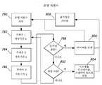
유도성 판독기 시스템(300)용 제품 레벨 스윕 회로를 나타내는 플로차트가 도 17에 도시되어 있다. 이 시스템은 단계(340)에서 웨이크 상태(wake state)에서 시작한다. 단계(342)에서, 시스템(300)은 제품 식별을 위해 각각의 1차 코일(334)을 스위핑한다. 공진 주파수와 만나면, 1차 코일(334)의 전류 레벨은 제품 식별 코일의 피드백이나 평균 피드백에 의해 설정된 베이스라인 전류 위로 증가할 수 있다. 그 다음 시스템은 단계(344)에서 제품 식별이 존재하는지를 질의한다. 단계(344)에서 1차 코일(334)의 부근 내에서 어떠한 식별된 제품도 없다면, 네트워크는 단계(346)에서 미리 결정된 시간량 동안 휴면한다. 제품 식별이 존재한다면, 단계(348)에서 네트워크는 남아 있는 각 제품의 양을 판정한다. 그 다음 네트워크는, 단계(350)에서, 제품 식별, 각 제품의 양, 및 선택사항으로서 고유의 유도성 판독기 식별자를 허브에 송신할 것이다.A flowchart illustrating the product level sweep circuit for
III.제품 용기 히터 시스템III.Products Container Heater System
본 발명의 제3 양태에 따르면, 제품 용기를 가열하기 위한 시스템이 제공된다. 이 시스템은, 제품 용기 및/또는 그 내용물의 온도에 기초하여 임피던스가 변하는 수동 온도 감지 회로 및 수동 식별 회로를 갖는 제품 용기를 포함할 수 있다. 이 시스템은 수동 식별 회로 및 수동 온도 감지 회로의 반사 임피던스를 모니터링하도록 구성된 비접촉식 전원을 더 포함할 수 있다. 제품 용기는, 식품, 음료, 기름, 토피컬 크림(topical cream), 또는 원하는 임의 형태의 물품을 지지하기 위한 임의의 용기를 포함할 수 있다. 제품 용기와 관련한 것으로 설명하였지만, 실시예들은 파트 IV에서 더욱 상세히 개시되는 바와 같이 컬링 아이롱(curling iron) 또는 헤어 스트레이트너(hair straightener)와 같은 휴대 기구와 함께 사용하도록 구성될 수 있다.According to a third aspect of the present invention, a system for heating a product container is provided. The system may include a product container having a passive temperature sensing circuit and a passive identification circuit whose impedance is varied based on the temperature of the product container and / or its contents. The system may further include a passive identification circuit and a non-contact power supply configured to monitor the reflected impedance of the passive temperature sensing circuit. The product container may include food, beverage, oil, topical cream, or any container for supporting any desired type of article. Although described with reference to a product container, embodiments may be configured for use with a portable device such as a curling iron or a hair straightener as described in more detail in Part IV.
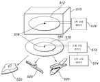
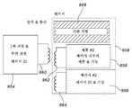
이제 도 18을 참조하면, 용기(360)는 온도 감지 회로(362) 및 강자성 재료(364)를 포함하는 것으로 도시되어 있다. 가열된 음료용 용기로서 도시되어 있지만, 용기(360)는, 예를 들어, 식료품, 로션, 세럼(serum), 및 치료 연고와 연계하여 이용될 수 있다. 일부 실시예들에서, 용기(360) 그 자체는 강자성 재료(364)로 형성될 수 있는 반면, 다른 실시예들에서는 강자성 재료(364)가 용기(360)의 표면에 가해질 수 있다. 용기(360)는 또한, 선택사항으로서 강자성 재료(364)를 실질적으로 에워싸는, 예를 들어, 발포 폴리스티렌 재료나 판지재를 포함한 하나 이상의 절연재를 포함할 수 있다. 절연재는 또한, 강자성 재료(364), 온도 감지 회로(362), 또는 양쪽 모두의 하나 이상의 표면 상에 보호층을 형성하기 위해, 캘리포니아주 어빙시의 Henkel Corporation에 의한 ELECTRODAG® 유전체 잉크와 같은 유전체 잉크를 포함할 수 있다.Referring now to FIG. 18, the
온도 감지 회로(362)는 가요성 비도전성 기판 상에 형성될 수 있으며, 유도성 소자(366), 직렬 공진 커패시터(368), 및 직렬 가변 저항(370)을 포함할 수 있다. 유도성 소자(366)는 인쇄된 트레이스 권선을 포함할 수 있고, 직렬 공진 커패시터(368)는, 온도 감지 회로(362)가 비접촉식 전원의 구동 또는 동작 주파수에 대응하는 공진 주파수를 포함하도록 하는 커패시턴스를 갖도록 선택될 수 있다. 유도성 소자(366) 및/또는 기타의 인쇄된 도전성 소자는 메릴랜드주 제섭시 Vorbeck Materials Corporation의 Vor-ink™로 형성될 수 있다. 가변 저항(370)은 용기(360) 또는 그 내용물의 온도의 함수로서 저항을 갖는 서미스터(thermistor)나 기타의 소자를 포함할 수 있다. 비도전성 기판(non-conducting substrate)이, 접착제, 예를 들어, 압력-감응 접착체(PSA)를 이용하여 용기(360)의 외부 표면에 가해질 수 있다.The
이 실시예에서, 비접촉식 전원은, 용기 내용물을 적어도 간접적으로 및 선택사항으로서 직접적으로 가열하기 위해 용기(360)에 전력을 제공한다. 특히, 비접촉식 전원은, 온도 센서 회로(360)의 반사 임피던스를 모니터링하는 한편 미리 결정된 범위의 주파수를 스위핑함으로써 추가의 가열이 요구되는지 여부 및 어느 정도까지 요구되는지를 판정할 수 있다. 서미스터(370)의 저항은 (대체로 표준 저항보다 더 많이) 온도에 따라 상당히 변할 수 있기 때문에, 비접촉식 전원은 동작 주파수 범위에 걸쳐 1차 탱크 회로에 대한 비접촉식 전원에서의 전류 및/또는 전압의 변화를 경험할 것이다. 1차 탱크 회로의 전류가 임계치를 지나면, 비접촉식 전원의 제어기는 그 이벤트가 발생한 주파수를 기록하고, 룩업 테이블을 이용하여 그 주파수를 용기(360)나 그 내용물의 온도와 상관시킬 수 있다. 용기(360)나 그 내용물의 온도가 원하는 온도보다 낮다고 판정되면, 비접촉식 전원은 강자성 재료(364) 및 그 대응하는 용기 내용물을 가열하기 위한 1차 탱크 회로에 걸쳐 적절한 시변동(time varying) 전압을 제공할 수 있다.In this embodiment, the non-contact power source provides power to the
본 발명의 또 다른 양태에 따른 제품 용기나 휴대 장치를 위한 유도성 가열 시스템이 도 19 및 도 20에 도시되어 있다. 유도성 가열 시스템은 비접촉식 전원(380) 및 제품 용기(400)를 포함한다. 비접촉식 전원(380)은, 전원(382), 전원(382)의 출력에 전기적으로 연결된 인버터(384), 및 직렬 커패시터(386) 및 1차 코일(388)을 포함하는 탱크 회로를 포함한다. 또한, 제어기(390)는, 메인 입력, 전원(382), 인버터(384), 및 1차 코일(388)에 인가되는 전력의 특성을 제어하기 위한 탱크 회로에 전기적으로 접속된다. 특히, 제어기(390)는, 1차 코일(388)에서 전력이 발생되는 주파수를 선택적으로 제어한다. 동작시, 비접촉식 전원(380)은 식별 주파수에서 1차 코일(388)에 전력을 인가한 다음 전류나 전압 센서를 이용하여 제품 용기의 반사 임피던스를 평가한다. 만일 제품 용기(400)가 식별 주파수에서 공진 주파수를 가진다면, 비접촉식 전원(380)은 제품 용기(400) 내의 히터 소자에 직접 또는 간접으로 전력을 공급하기 위해 메모리로부터 동작 파라미터들을 복구할 수 있다.An inductive heating system for a product container or portable device according to yet another aspect of the present invention is shown in Figures 19 and 20. The inductive heating system includes a
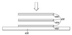
이 실시예에서, 제품 용기(400)는 3개의 격리된 공진 회로(402, 404, 406)와 강자성 재료(408)를 포함한다. 강자성 재료(408)는 제품 용기(400)의 표면 상의 평판, 띠, 또는 코팅 형태일 수 있다. 대안으로서, 제품 용기(400) 그 자체가 강자성 재료로 형성될 수 있다. 강자성 재료(408)는, 유도 자계에 더 이상 반응하지 않는 뚜렷한 퀴리점 온도를 포함하여, 가열 중인 장치나 패키지에 효과적으로 최대 온도를 부여할 수 있다. 재료 및 특정 퀴리점 온도의 선택은 응용마다 특유하며, 제품이 특정한 온도를 요구하는 상황이나 안전의 이유상 최대 온도가 규제되어야 하는 상황에서 이로울 수 있다. 전술된 바와 같이, 비접촉식 전원(380)은 1차 코일(388)의 전류, 전압 또는 위상을 모니터링하면서 미리 결정된 범위의 주파수를 스위핑함으로써 제품 용기(400)의 신원을 판정할 수 있다. 제품 용기(400)의 격리된 공진 회로(402, 404, 406)는, 1차 코일(388)에 인가된 주파수에 따라 비접촉식 전원(380)에 상이하게 반응한다. 공진 코일(402, 404, 406)의 상이한 반응은 1차 코일(388)에서 변화하는 전류, 전압 또는 위상을 야기한다. 예를 들어, 1차 코일(388)의 전류가 임계치를 초과하거나, 국지적 최대값이나 기타의 기준을 달성하면, 제어기(390)는 이벤트가 발생한 주파수를 기록할 수 있다. 주파수 범위를 스위핑함으로써, 비접촉식 전원(390)은, 선택사항으로서, 격리된 공진 회로(402, 404, 406) 각각의 공진 주파수를 포함하는 유도성 식별 프로파일을 판정하고 기록할 수 있다. 그 다음, 제어기(390)는 파트 VII에서 개시된 바와 같이 유도성 식별 프로파일을 고유 장치 또는 패키지 식별 코드로 변환할 수 있다. 비접촉식 전원(380)은 그 다음, 그 식별 코드를 이용하여 용기(400)와 그 내용물의 특정한 요구에 따라 용기(400)에 전력을 제공한다. 그러면, 비접촉식 전원(380)에 의해 인가되는 전력은 제품 용기(380)를 가열하기 위해 강자성 스트립(408)에 와전류(eddy current)를 유도할 수 있다. 선택사항으로서 도 20에 도시된 바와 같이, 비접촉식 전원(380)은, 제품 용기(400)와 비접촉식 전원(380)의 정렬을 위한 공간적 자유를 높이기 위하여 제품 용기(400)의 가열시에 유도 자기장 강도를 성형, 포커싱, 재분배 또는 부스팅하도록 작용하는 격리된 재공진기(re-resonator) 코일(392)을 포함할 수 있다.In this embodiment, the
도 21 및 도 22에 도시된 바와 같은 또 다른 실시예에서, 격리된 공진 회로(402, 404, 406) 각각은 직렬 저항성 소자(410)와, 저항성 소자(410)를 단락시키는 바이패스 소자(412)를 포함한다. 저항성 소자(410) 및 바이패스 소자(412)의 구성은 제조시에 설정되거나 제품 용기(400)의 판매자에 의해 또는 최종 사용자에 의해 선택가능할 수 있다. 예를 들어, 바이패스 소자(412)의 상태를 선택하기 위해 물리적 스위치가 이용될 수 있다. 물리적 스위치는 푸시-버튼, 다극 슬라이더 스위치, 또는 다극 회전 스위치일 수 있다. 대안으로서, 격리된 공진 회로(402, 404, 406)는 패키지(400)의 일부를 형성하는 비도전성 기판(414) 상의 도전성 잉크로 형성될 수 있으며, 여기서 바이패스 소자(412)는 비도전성 기판(414)의 일부가 나머지 패키지(400)로부터 분리되는 것에 응답하여 개방된다. 이들은, 보호 잉크, 라벨 또는 코팅의 또 다른 층에 의해 밀봉될 수 있다. 사용자가 바이패스 소자들(414) 중 하나를 개방하기를 원하는 경우, 사용자는 천공(416)을 따른 패키지의 지정된 부분을 찢어낼 수 있다. 이하의 표 1에 나타난 바와 같이, 공진 회로(402, 404, 406)의 상태는 제품 용기(400) 내의 식료품의 원하는 온도를 나타낼 수 있으며, 여기서 "하이"는 사용자가 개방한 대응하는 공진 회로의 바이패스 소자를 나타낸다.Each of the isolated resonant circuits 402,404 and 406 includes a series
표 1 - 선택된 제품 용기 온도Table 1 - Selected Products Container Temperature
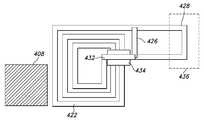
선택사항으로서 도 23에 도시된 바와 같이, 격리된 공진 회로(420)는, 비도전성 기판(430) 상에 형성된 트레이스 권선(422), 인쇄된 잉크 커패시터(424), 탄소 인쇄된 저항성 소자(426), 기판(430)의 천공된 부분 상에 형성된 바이패스 소자(428), 및 인쇄된 잉크 절연층(434)을 가로질러 트레이스 권선의 단부들을 상호접속하는 인쇄된 잉크 점퍼(432)를 포함한다. 기판의 일부는 절단 탭(436)을 포함하며, 절단 탭의 제거는 바이패스 소자(428)를 개방하여 전류가 탄소 인쇄된 저항(426)을 통해 흐르도록 허용하므로, 격리된 공진 회로(420)의 반사 임피던스를 변경시킨다. 전술된 바와 같은 방식으로, 비접촉식 전원(380)은 격리된 공진 회로(420)의 공진 주파수나 반사 임피던스에 기초하여 제품 용기(400)를 식별할 수 있으며, 제품 용기(400)로부터의 절단 탭(436)의 존재 또는 부재에 기초하여 가열 소자(408)에 유도 전력을 제공할 수 있다. 이 실시예는, 예를 들어, 식료품, 예를 들어, 제품 용기(400) 내에 포함된 한 캔의 수프에 원하는 가열량을 제공하는 데 있어서 유용할 수 있다. 온도는 처음에 제품 ID에 의해 설정될 수 있고 선택은 이 베이스 레벨에 대한 오프셋을 허용할 수 있다. 또한, 격리된 공진 회로들은 도 24에 도시된 바와 같이 패키징 재료 상에 서로 중첩될 수 있다. 도 24에 도시된 바와 같이, 격리된 공진 회로(402, 404, 406)는 대응하는 절연 잉크(438)의 층들에 의해 분리된다. 선택사항으로서 도 25에 도시된 바와 같이, 격리된 공진 회로(420)는 선택사항적 인쇄된 잉크 공진 커패시터를 포함하지 않는다. 절연체층과 복수의 회로층을 이용하여 작은 공간 내에 복수의 공진 회로들이 인쇄될 수 있다. 게다가, 강자성 재료(408)는, 도 26에 도시된 바와 같이, 코어를 형성하거나, 별개의 강자성 코어와 연계하여 사용될 수 있다. 이 실시예에서, 절단 탭(436)과 인쇄된 잉크 커패시터(424) 양쪽 모두는, 격리된 공진 회로(420)에서의 이들의 선택사항적 포함을 나타내기 위해 생략된다. 도 27의 격리된 공진 회로(420)는 격리된 공진 회로(440)와 1차 코일(388) 사이의 유도성 결합을 향상시키기 위해 인쇄된 차폐 재료(440)를 더 포함할 수 있다. 차폐 재료는 금속 패키지로부터 코일을 분리하기 위해 금속 패키지와 조합하여 이용될 수 있다. 예를 들어, 차폐 잉크는 금속 패키지로부터 코일을 차폐할 수 있는 금속 분말을 포함할 수 있다. 이들 잉크 내의 비도전성 분말의 적재는 특정한 타입의 자기 또는 금속 속성과 함께 차폐 속성에 영향을 줄 수 있다.23, the isolated
도 28 및 도 29에 도시된 또 다른 실시예에서, 비접촉식 전원(380)은 휴대 장치(400)의 표면을 간접 가열하기 위해 휴대 장치(400), 예를 들어, 제품 용기에 전력을 제공한다. 이 실시예에서, 휴대 장치는, 2차 탱크 회로를 형성하는 2차 코일(442) 및 직렬 공진 커패시터(444), 2차 탱크 회로의 출력에 접속된 정류 및 충전 부회로(446), 정류 및 충전 부회로(446)의 출력에 접속된 배터리(448), 배터리(448)의 출력에 접속된 히터 소자(450), 히터 소자(450)로부터의 열을 전도에 의해 수신하는 가열가능한 표면(452), 가열가능한 표면(452)의 온도를 검출하고 출력을 갖는 온도 센서(454), 및 온도 센서(454)의 출력에 접속된 제어기(456)를 포함한다. 이 실시예에서, 비접촉식 전원(380)은 도 18 내지 도 21과 연계하여 전술된 바와 같이 강자성 재료를 직접 가열하지 않는다. 대신에, 비접촉식 전원(380)은 휴대 장치(400)에 전력을 제공하여 배터리(448)를 충전시키고, 배터리는 히터(450)와 가열가능한 표면(452)을 작동시키는 대응하는 전력을 제공한다. 이 실시예에서, 히터(450)는 장치(400)가 비접촉식 전원(380)에 근접하지 않은 때 계속 동작할 수 있다. 선택사항으로서 도 29에 도시된 바와 같이, 비접촉식 전원(380)은, 장치(400)와 비접촉식 전원(380)의 정렬을 위한 공간적 자유를 높이기 위하여 장치(400)의 전원공급시에 유도 자기장 강도를 성형, 포커싱, 재분배 또는 부스팅하는 격리된 재공진기 코일(392)을 포함할 수 있다. 추가로, 충전 및 가열은 동시에 발생할 수 있다.28 and 29, the
도 30 및 도 31에 도시된 또 다른 실시예에서, 휴대 장치(400), 예를 들어, 제품 용기는 3개의 격리된 공진 회로(460, 462, 464) 및 휴대 장치 부하(466)를 포함한다. 이 실시예에서, 비접촉식 전원(380)은 격리된 공진 회로(460, 462, 464)의 반사 임피던스에 따라 2차 탱크 회로(468)를 이용하여 휴대 부하(466)에 전력을 제공한다. 도 21과 연계하여 전술된 바와 같이, 각각의 격리된 공진 회로(460, 462, 464)는 저항성 소자(470) 및 바이패스 소자(472)를 포함한다. 닫힌 상태에서, 바이패스 소자(472)는 저항성 소자(470)를 효과적으로 단락시키고, 대응하는 격리된 공진 회로의 임피던스를 효과적으로 변화시킨다. 비접촉식 전원(380)은 그 다음, 격리된 공진 회로(들)의 임피던스 변화에 기초하여 원격 장치(400)에 전력을 제공할 수 있다. 예를 들어, 공진 회로들(460, 462, 464)의 "n"개의 상태는 2n개의 전력 레벨들 중 어느 것이 휴대 장치(400)에 인가되어야 하는지를 나타낼 수 있다. 이하의 표 2에 나타낸 바와 같이, "0"은 대응하는 공진 회로의 바이패스 소자가 비도전 상태에 있다는 것을 나타내고, "1"은 대응하는 공진 회로의 바이패스 소자가 도전 상태에 있다는 것을 나타낸다.30 and 31, the
표 2- 선택된 전력 레벨Table 2 - Selected Power Levels
일단, 1차 코일(388)에서의 전력의 동작 주파수, 진폭, 듀티 사이클, 펄스폭, 위상이나 기타 특성을 포함할 수 있는 원하는 전력 레벨이 선택되면, 비접촉식 전원(380)은 실질적으로 도 28 및 도 29와 연계하여 전술된 바와 같이 휴대 장치의 표면을 가열하기 위해 휴대 장치(400)에 전력을 제공한다. 선택사항으로서 도 31에 도시된 바와 같이, 비접촉식 전원(380)은, 원격 장치(400)와 비접촉식 전원(380)의 정렬을 위한 공간적 자유를 높이기 위하여 원격 장치(400)의 가열시에 유도 자기장 강도를 성형, 포커싱, 재분배 또는 부스팅하도록 작용하는 격리된 재공진기 회로(392)를 포함할 수 있다. 유사한 방식으로, 원격 장치(400)는, 비접촉식 전원(380)에 의해 발생된 유도 자기장의 수신을 향상시키기 위해, 직렬 공진 회로로서 도시된 재공진기 회로(474)를 포함할 수 있다.Once the desired power level, which may include the operating frequency, amplitude, duty cycle, pulse width, phase, or other characteristics of the power at the
도 32 및 도 33에 도시된 또 다른 실시예에서, 원격 장치 또는 제품 용기(400)는 공진 온도 센서 회로(468)를 포함한다. 이 실시예에서, 공진 온도 센서 회로(468)는 2차 코일(442), 직렬 커패시터(444), 및 온도 센서(454)를 포함한다. 온도 센서는, 열전대(thermocouple), 열전대의 출력에 접속된 아날로그 대 디지털 변환기, 및 아날로그 대 디지털 변환기의 출력에 접속된 가변 임피던스 소자를 포함할 수 있다. 동작시, 강자성 재료(452)의 온도 변화는 공진 온도 센서 회로(468)의 임피던스 변화로 이어진다. 이 실시예에서, 비접촉식 전원(380)은 공진 온도 센서 회로(468)의 반사 임피던스의 변화를 검출하고, 강자성 재료(452)의 온도에서의 대응하는 변화를 식별하며, 필요하다면 전력 출력을 조정하도록 동작할 수 있다. 선택사항으로서 도 33에 도시된 바와 같이, 비접촉식 전원(380)은, 원격 장치(400)와 비접촉식 전원(380)의 정렬을 위한 공간적 자유를 높이기 위하여 원격 장치(400)의 가열시에 유도 자기장 강도를 성형, 포커싱, 재분배 또는 부스팅하도록 작용하는 격리된 재공진기 회로(392)를 포함할 수 있다.In another embodiment shown in Figures 32 and 33, the remote device or
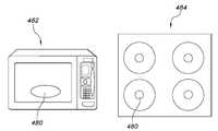
도 75에 도시된 또 다른 실시예에서, 공진 온도 회로(468)는 식료품 내에 포함된다. 위의 도 32 및 도 33과 연계하여 개시된 바와 같이, 공진 온도 회로(468)는, 열전대(thermocouple), 열전대의 출력에 접속된 아날로그 대 디지털 변환기, 및 아날로그 대 디지털 변환기의 출력에 접속된 가변 임피던스 소자를 포함할 수 있다. 동작시, 식료품의 온도 변화는 공진 온도 센서 회로(468)의 임피던스 변화로 이어질 수 있다. 이 실시예에서, 무선 전력 판독기 코일(480)은, 공진 온도 센서 회로(468)의 반사 임피던스의 변화를 검출하고 식료품의 온도에서의 대응하는 변화를 식별하도록 동작할 수 있다. 본 실시예에서, 식료품은 위의 도 18 내지 도 33에 개시된 무선 전력 시스템 및 방법에 따라 가열될 수 있다. 다른 실시예들에서, 종래의 방법에 따라 식료품이 가열될 수 있다. 예를 들어, 무선 전력 판독기 코일(480)은 마이크로웨이브 오븐(482) 및/또는 스토브탑(484), 예를 들어, 가스레인지나 전자레인지의 일부를 형성할 수 있다. 식품이 원하는 온도에 도달하면, 무선 전력 판독기 코일(480)은 마이크로웨이브 및/또는 스토브와 연관된 제어기에 출력을 제공할 수 있다. 이 점에서, 마이크로웨이브 또는 스토브 제어기는 식료품의 과익힘(overcooking)을 방지하기 위해 마이크로웨이브 또는 스토브의 동작을 정지시킬 수 있다. 또한, 제어기는 식료품의 설익힘(undercooking)을 방지하기 위해 공진 온도 센서 회로(468)의 출력을 모니터링할 수 있다. 공진 온도 센서 회로(468)가 식료품의 온도를 직접 모니터링하는 것으로 전술되었지만, 일부 응용에서는 식료품의 온도를 간접적으로 모니터링하는 것이 바람직할 수 있다. 예를 들어, 공진 온도 센서 회로(468)는 또한, 베이킹 팬, 후라이팬, 포트 등의 온도를 단독으로 또는 그 내부에 포함된 식료품의 온도와 연계하여 모니터링할 수 있다. 이들 및 다른 응용에서, 예를 들어, 무선 전력 판독기 코일(480)의 동작을 다르게 간섭할 수도 있는 마이크로웨이브나 기타의 전자기 방출로부터 공진 온도 회로(468)를 잠재적으로 격리시키는 마이크로웨이브 차폐물을 제공하는 것이 바람직할 수 있다.In another embodiment shown in Figure 75, the
IV.휴대 장치 히터 시스템IV.Portable Heater System
본 발명의 또 다른 양태에서, 휴대 가열 기구에 무선 전력 소스를 제공하기 위한 시스템이 도 34 내지 도 37에 나타나 있으며 개괄적으로 500으로 지정되어 있다. 이 시스템은 일반적으로 그 특정한 전력 요구에 기초하여 휴대 기구(520)에 전력을 제공하도록 구성된 비접촉식 전원(510)을 포함한다.In another aspect of the present invention, a system for providing a wireless power source to a portable heating mechanism is shown in Figures 34-37 and is generally designated as 500. [ The system generally includes a
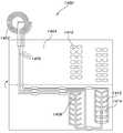
도 34 및 도 35에 도시된 한 실시예에서, 비접촉식 전원(510)은 코드없는 의류 다리미(520)에 전력을 제공하기 위해 격납가능한 다림판(stowable ironing board, 502)에 의해 지지되고 있다. 비접촉식 전원(510)은 코드없는 다리미(520) 내에 포함된 2차 코일(522)과 유도 결합하는 하나 이상의 1차 코일(512)을 포함할 수 있다. 다리미(520)는 2차 코일(522)의 출력에 전기적으로 접속된 하나 이상의 가열 소자(524, 526)를 포함할 수 있다. 세라믹 가열 기판(528)은, 들러붙지 않는 표면(non-stick surface, 530), 예를 들어, 델라웨어주 윌밍턴시 Dupont에 의한 Teflon® 재료와 하나 이상의 가열 소자(524, 526) 사이에 위치할 수 있다. 다리미(520)는 또한, 실질적으로 앞서 도 18에 개시된 바와 같이 강자성 가열 소자를 포함할 수 있다. 예를 들어, 내부 배터리를 충전하면서 강자성 재료를 가열하는 것은, 비접촉식 전원(510)으로부터 장치가 제거될 때 저장된 에너지가 나중에 가열 소자(524, 526)에서 이용되는 것을 허용할 수 있다.In one embodiment shown in FIGS. 34 and 35, the
비접촉식 전원(510)의 동작은 도 36 및 도 37을 참조하여 이해할 수 있다. 비접촉식 전원(510)은, 상기 파트 I-III에 개시된 바와 같이 가열, 전력공급, 배터리 충전 및/또는 식별자 및 센서의 판독에 이용될 수 있다. 예를 들어, 비접촉식 전원(510)을 작동시키기 위한 방법은, 단계(540)에서 시스템을 초기화하고 단계(542)에서 제1 1차 코일을 구동하는 것을 포함한다. 단계(544)에서, 비접촉식 전원(510)은, 실질적으로 도 19 및 도 20과 연계하여 전술된 바와 같이 코드없는 다리미나 기타의 휴대 장치가 제1 1차 코일(512)에 인접해 있는지를 판정할 수 있다. 만일 다리미(510)가 존재한다면, 단계(546)에서 전원(510)은 제1 1차 코일(512)에 전력을 제공할 수 있다. 만일 판정 단계(544)에서 다리미(520)가 존재하지 않으면, 단계(548)에서 전원(510)은 제2 1차 코일(514)을 구동할 수 있다. 만일 다리미가 제2 1차 코일(514)에 근접해 있다면, 단계(550)에서 전원(510)은 제2 1차 코일(514)에 전력을 제공할 수 있다. 그러나 만일 다리미가 존재하지 않는다면, 전원(510)은 동일한 방식으로 다음 1차 코일을 샘플링한다(sample). 따라서, 비접촉식 전원(510)은 코드없는 다리미(540)에 근접한 1차 코일들에만 전력을 제공하기 위해 다림판(502)과 연관된 각각의 1차 코일을 순차적으로 샘플링할 수 있다. 도 37에도 역시 도시된 바와 같이, 비접촉식 전원(510)은, 휴대 장치(520), 즉 이 경우에는 다리미가 비접촉식 전원에 근접해 있는지를 먼저 평가할 수 있다. 단계(554)에서 사용자에 의해 스타트 버튼이 눌러지거나 다리미(520)가 비접촉식 전원(510)에 근접해 있다면, 비접촉식 전원은 원하는 1차 코일(512)에 전력을 공급하여 코드없는 다리미(540)의 다림면을 가열한다. 판정 단계(556)에서, 전원(510)은, 실질적으로 도 28 및 도 29와 연계하여 전술된 바와 같이 다림면이 사용 준비가 되었는지(예를 들어, 원하는 온도인지)를 판정할 수 있다. 만일 다림면이 사용준비가 되어 있지 않다면, 단계(556)에서 프로세스는 스스로를 반복한다. 그러나 만일 다림면이 사용 준비가 되어 있다면, 다림판(510)이나 다리미(520) 상의 디스플레이는, 프로세스 단계(560)에 도시된 바와 같이, 다리미가 사용 준비되어 있다는 시각적 또는 청각적 표시를 사용자에게 제공한다.The operation of the
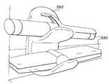
위의 파트 III에서 언급한 바와 같이, 비접촉식 전원은, 휴대 장치의 신원에 기초하여 및/또는 하나 이상의 격리된 공진 회로의 상태에 기초하여 휴대 장치에 전력을 제공할 수 있다. 반복하면, 일부 실시예들에서, 휴대 장치(520)는 도 38에 도시된 바와 같은 비접촉식 전원(510)의 1차 코일(512)에 의해 직접 통전되는(energized) 강자성 재료(570)를 포함할 수 있다. 다른 실시예들에서, 휴대 장치(520)는 대안으로서 도 39에 도시된 바와 같은 비접촉식 전원(510)의 1차 코일(512)에 결합된 2차 코일(580)에 의해 그 자체가 전력공급되는 배터리(584)의 출력에 전기적으로 접속된 히터 소자(572)를 포함할 수 있다. 이들 실시예에서, 비접촉식 전원(510)은 강자성 재료(570)를 간접적으로 가열하여 열을 발생시키면서 동시에 휴대 장치(520) 내의 2차 코일(580)에 전력을 제공한다. 비접촉식 전원(510)은 전술된 바와 같이 센서와 선택 스위치로부터의 데이터를 판독할 수 있다. 도 40에 도시된 바와 같이, 가열 소자(582)는 부트-인서트(boot-insert)와 같은 풋웨어 제품의 전부 또는 일부를 포함할 수 있다. 가열 소자(582)가 풋웨어 제품(586) 내에 놓이면, 가열 소자(582)는 비접촉식 전원 매트(588)에 근접할 때 가열되어 풋웨어 제품(586)의 건조를 가속한다. 도 41 내지 도 43에도 역시 도시된 바와 같이, 비접촉식 전원(510)은 헤어 스타일링 아이롱(hair styling iron)(590)을 가열하는 데 이용될 수 있다. 비접촉식 전원(510)은 다양한 장치 홀딩 랙(592) 내에 병합되어 실질적으로 전술된 바와 같이 헤어 스타일링 아이롱(590)을 식별하고 전력을 제공할 수 있다.As mentioned above in Part III, the non-contact power source may provide power to the portable device based on the identity of the portable device and / or based on the state of the one or more isolated resonant circuits. Again, in some embodiments, the
반복하면, 가열 기구 시스템(500)은 비접촉식 전원(510)과 휴대 가열 장치(520)를 포함할 수 있다. 비접촉식 전원(510)은 1차 코일(512)을 포함할 수 있고 휴대 가열 장치(520)는 배터리에 전기적으로 접속된 2차 코일(522)을 포함할 수 있다. 휴대 가열 장치(520)는 강자성 가열 소자(524) 및 노출된 표면(530)을 더 포함할 수 있으며, 여기서 강자성 가열 소자(524)는 배터리의 출력에 전기적으로 접속된다. 가열 기판(528)은 노출된 표면(530)과 가열 소자(524) 사이에 위치할 수 있으며, 비접촉식 전원은 강자성 재료를 가열하면서 동시에 배터리를 충전한다. 배터리로부터의 에너지는 강자성 가열 소자(524)를 가열하는 데에도 이용될 수 있다. 휴대 가열 장치(520)는 유도성 식별 프로파일을 정의하는 수동 식별 회로를 더 포함할 수 있으며, 선택사항으로서 2차 코일(522)을 포함한다.Again, the heating mechanism system 500 may include a
V.제품 정렬 시스템V.Product Sorting System
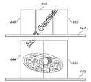
본 발명의 또 다른 양태에 따르면, 제품 정렬 시스템이 도 44 내지 도 46에 도시되어 있으며, 개괄적으로 600으로 지정되어 있다. 이하에서 논의되는 바와 같이, 제품 정렬 시스템(600)은 디스플레이면의 1차 코일과 제품이나 제품 패키지의 2차 코일 사이의 결합 계수를 향상시킬 수 있다.According to another aspect of the present invention, the product alignment system is shown in Figures 44 to 46 and is generally designated 600. [ As discussed below, the
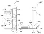
이제 도 44를 참조하면, 제품 정렬 시스템(600)은 디스플레이면(606) 및 복수의 제품이나 제품 용기(620, 622)를 포함한다. 디스플레이면(606)은 복수의 행을 지지할 수 있는데, 각각의 행은 선택사항으로서 아래쪽으로 경사진 기다란 지지 부재나 선반(608), 측방향으로 이격되고 위쪽으로 연장된 가이드 레일(610, 612), 선두 제품(620, 622)의 앞쪽에서 가로놓이고 위쪽으로 연장된 립(lip, 614)에 의해 정의된다. 각각의 행은, 선두 제품이 각 행(604, 606)으로부터 제거될 때 제품(620, 622)을 디스플레이면(602)의 앞쪽으로 밀기 위해 스프링(616) 및 가로놓인 가이드판(618)을 포함할 수 있다. 대안으로서, 또는 조합하여, 각 제품(620, 622)은 선두제품이 제거될 때 디스플레이 랙의 앞쪽 부분을 향하여 중력 공급될(gravity fed) 수 있으며, 여기서 스프링(616) 및 가이드판(618)은 제공되거나 제공되지 않을 수 있다.44, the
도 44에도 역시 도시된 바와 같이, 디스플레이면(606)은 제1 및 제2 1차 코일(624, 626)을 포함한다. 제1 및 제2 1차 코일(624, 626)은, 각각이 디스플레이면(606)의 대응하는 고리형 오목부(annular recess) 내에 수용되는 수평으로 배치된 코일들을 포함할 수 있다. 선택사항으로서, 각각의 1차 코일(624, 626)은 행의 최선두부에 배치되어 각 행의 선두 제품의 아래에 놓여 선두 제품에 전력을 공급한다. 또한, 각 1차 코일(624, 626)은 윗쪽으로 연장되는 립(614)을 따라 또는 립 내에서 길이방향으로 연장되는 제1 및 제2 도전성 스트립(628, 630)에 전기적으로 접속된 연관된 전원(632)을 포함할 수 있다. 각 행의 최선두부의 중량 작동형 센서는 선두 제품의 존재 또는 부재를 검출함으로써, 대응하는 전원의 동작을 활성화하거나 기타의 방식으로 개시할 수 있다. 제품(620, 622)은 각각, 선택사항으로서는 인쇄된 트레이스 권선 및 인쇄된 2차 탱크 회로를 포함한, 2차 코일(634, 636)을 포함할 수 있다.As also shown in FIG. 44, the
각 선두 제품이 대응하는 행으로부터 제거될 때, 스프링(616) 및 가이드판(618)은 선두 제품을 1차 코일(624, 626) 위에 놓은 위치로 보냄으로써, 1차 코일(624, 626)과 2차 코일(634, 636) 사이의 결합 계수를 향상시킨다. 선택사항으로서, 선두 제품과 연관된 2차 코일은 일관적으로 또는 거의 일관적으로 디스플레이면(606) 내의 1차 코일 위에 놓일 것이다. 이 점에서, 제품 정렬 시스템(600)은 제품들을 소비자가 보고 쉽게 접근할 수 있는 위치로 보내는 한편, 동시에 하나 이상의 제품 LED, OLED, LCD 디스플레이, 스피커, 배터리, 또는 선두 제품이나 그 패키지와 연관된 기타의 장치에 무선 전력 소스를 제공한다. 또한, 제품 정렬 시스템(600)은 각 선두 제품이 구매 전에 충분히 적재되어 있음을 보장할 수 있으며, 앞서 개시된 바와 같이 이러한 제품의 식별, 추적, 및 재주문을 보조할 수 있다.The
본 실시예는 도 45 및 도 46을 참조하여 더욱 잘 이해될 수 있으며, 여기서 제품 정렬 시스템(600)은 서로 이격되어 있는 제1 및 제2 평행 디스플레이면(640, 642)을 포함한다. 각 디스플레이면(640, 642)은 각 선두 제품 아래에 놓인 디스플레이면의 전면부에서 1차 코일을 포함할 수 있다. 예를 들어, 1차 코일은 디스플레이면의 최선두부에 배치되어 실질적으로 선두 제품, 예를 들어, 디스플레이면 상의 최선두부 물품이나 물품들만의 아래에 놓여, 이들에 전력을 공급할 수 있다. 디스플레이면(640, 642)은 소매 잡화점에서 흔한 디스플레이 선반이나 엔드 캡(end cap)을 구성할 수 있다. 디스플레이면(640, 642)은, 제품, 제품 용기 및/또는 제품 디스플레이를 포함한, 복수의 물품을 지지할 수 있다. 예를 들어, 하위 디스플레이면(640)은 제1 및 제2 물품(644, 646)을 포함할 수 있고, 상위 디스플레이면(646)은 제3, 제4, 및 제5 물품(648, 650, 652)을 포함할 수 있다. 각 물품은, 배터리나 커패시터와 같은 하나 이상의 내부나 외부의 에너지 저장 장치를 포함할 수 있다. 대안으로서, 이들 물품들은 에너지 저장 장치와 통상 연관되지 않는 제품을 포함할 수 있다. 예를 들어, 물품들은 상이한 크기나 균일한 크기의 시리얼 제품(cereal product)군을 포함할 수 있다.This embodiment can be better understood with reference to Figures 45 and 46 wherein the
도 46과 연계하여 앞서 언급한 바와 같이, 각 1차 코일(624, 626)은 대응하는 선두 물품과 연관된 2차 코일(634)에 전력을 제공할 수 있다. 2차 코일(634)은 무선 전력을 수신하도록 구성된 임의의 회로를 포함할 수 있다. 예를 들어, 2차 코일(634)은, 압력 감응 접착제(PSA)를 포함한 가요성의 비도전성 기판 상에 형성된 인쇄된 탱크 회로를 포함할 수 있다. 이와 같이, 2차 코일(634)은 제품이나 제품 패키지에 접속하기 위한 제1 및 제2 전기 콘택을 포함하는 로우-프로파일 스티커(low-profile sticker) 상에 형성될 수 있다.46, each
제품이나 제품 패키지(620)는 임의의 수의 방식으로 2차 회로에 전달되는 전력을 이용할 수 있다. 예를 들어, 2차 코일(634)은, 정류 LED, 배터리, 스피커 회로, 및/또는 일련의 LED, OLED, LCD 스크린 또는 e-잉크 디스플레이를 가로질러 부하에 전력을 제공할 수 있다. 배터리, LED, 스피커, e-잉크 디스플레이 또는 기타의 장치이건 간에 대응하는 장치의 제어는 이하의 파트 VI에서 설명되는 방식으로 복수의 격리된 공진 회로를 이용하여 달성될 수 있다. 대안으로서, 대응하는 부하의 제어는, 상이한 부하들 사이에서 전력을 전환하기 위해 하나 이상의 마이크로컨트롤러-제어형 스위치와 조합한 단 하나의 2차 코일에 의해 달성될 수 있다.The product or
도 45 및 도 46을 다시 참조하면, 전원(632)은 제품이나 제품 패키지의 적어도 하나의 양태를 제어할 수 있다. 예를 들어, 제1 상태에서, 시리얼 박스로 도시된 각각의 패키지는 e-잉크 그래픽을 포함할 수 있다. 도 45에서, e-잉크 그래픽은 각 시리얼 박스의 전방면과 동일한 면적에 걸치도록(coextensive) 비례적으로 크기조정된다. 따라서, 그래픽은 5회 반복, 즉, 각 선두 시리얼 박스에 대해 한번 씩 반복된다. 그러나, 도 46에 도시된 바와 같이, 각 시리얼 박스에 대한 e-잉크 그래픽은 전원(632)에 응답하여 변할 수 있다. 예를 들어, 전체 그래픽이 5개의 시리얼 박스의 디스플레이면 전체에 걸쳐 딱 맞게 비례하도록, 시리얼 박스에 대한 디스플레이면이 원래의 그래픽의 일부만을 포함할 수 있다. 크기 재조정 외에도, 전체 그래픽이나 그 일부만을 포함한 그래픽이 애니메이트되거나 조명될 수 있다. 이런 방식으로, 제품이 디스플레이면 상에 머물러 있는 동안 패키징 그래픽이 변경될 수 있으며, 그래픽은 선택사항으로서 비접촉식 전원을 이용하여 업로드된다. 또한, e-잉크 그래픽은 세일이나 계절에 대응하도록 제품 패키징이나 표지판을 자동으로 재구성하는 데 이용될 수 있거나, 임의 개수의 다른 가능한 요인에 기초하여 제품 패키징이나 표지판을 자동으로 재구성하는 데 이용될 수 있다. 이 실시예는, 선택사항으로서, 인쇄된 스피커 회로, 식별 회로, 및 이하의 파트 VI에서 더 상세히 논의되는 다른 실시예들과 연계하여, POS에서 패키지나 패키지들을 홍보하거나 기타의 방식으로 주목을 끌기 위해 시각적 출력을 생성하는 데 적합하다.45 and 46, the
반복하면, 제품 정렬 시스템(600)은, 복수의 패키지(620, 622)를 슬라이딩가능하게 지지하는 선반 유닛(606), 선반 유닛에 의해 지지되고 복수의 패키지(620, 622)를 선반 유닛(606)의 전면부쪽으로 밀도록 구성된 제품 밀개(pusher, 616), 및 선반 유닛(606)의 전면부에 의해 지지되어 시변동 전자기장을 생성하는 1차 코일(624)을 포함할 수 있다. 1차 코일(624)은 선반 유닛 윗면에 대체로 수직한 중심축을 정의할 수 있다. 가이드판(618)은 복수의 패키지(620, 622)를 선반 유닛의 전면부에서 위쪽으로 연장되는 립(614) 쪽으로 편향시킬 수 있다. 패키지들 각각은 또한, 부하에 전기적으로 접속된 2차 코일(624)을 지지하기 위한 베이스를 정의할 수 있다. 제품 정렬 시스템을 제어하기 위한 대응하는 방법은, 1차 코일(624, 626)을 포함하는 선반을 제공하는 단계, 선반에 의해 지지되며 부하에 접속된 2차 코일을 갖는 제품을 제공하는 단계, 1차 코일 위에 놓이도록 2차 코일을 정렬하는 단계, 및 무선 전력 소스를 부하에 제공하기 위해 시변동 전류로 1차 코일을 구동하는 단계를 포함할 수 있다. 앞서 언급한 바와 같이, 부하는, 예를 들어, LED, e-잉크 디스플레이, LCD 디스플레이, 전계발광 디스플레이, 정전 스피커 또는 배터리 중 하나를 포함할 수 있다. 이 방법은, 2차 코일의 공진 주파수에 대응하는 동작 주파수로 1차 코일을 구동하는 단계를 더 포함할 수 있다.The
VI.유도성 제품 및 제품 패키징 시스템VI.Inductive product and product packaging system
본 발명의 또 다른 양태에 따르면, 제품 패키징과 연관된 하나 이상의 부하에 무선 전력 소스를 공급하기 위한 시스템이 제공된다. 이 시스템은, 하나 이상의 시각적 소자, 스피커 소자 또는 양쪽 모두에 직접 또는 간접으로 연결된 2차 탱크 회로를 갖는 제품 용기를 포함할 수 있다.According to yet another aspect of the present invention, a system is provided for supplying a wireless power source to one or more loads associated with product packaging. The system may include a product container having a secondary tank circuit connected directly or indirectly to one or more visual elements, speaker elements, or both.
이제 도 47을 참조하면, 시스템은, 근처의 제품 및/또는 제품 패키징(720)과 연관된 2차 회로에 능동적으로 응답하기 위해 디스플레이면과 연관된 비접촉식 전원(700)을 포함한다. 파트 III-IV에서 개시된 유도성 가열 시스템과 연계하여 전술된 바와 같이, 비접촉식 전원(700)은 패키지(720) 및/또는 그 내용물을 수동 유도성 통신을 통해 식별하도록 동작할 수 있다. 식별 및 인증시에, 비접촉식 전원(700)은 미리 결정된 프로파일에 따라 패키지(720)에 전력을 제공할 수 있다. 대안으로서, 식별 및 인증시에, 비접촉식 전원(700)은, 수동 통신 모드로부터, 제품이나 제품 용기(720) 내의 2차 회로에 의해 전송된 데이터 신호에 따라 전력을 제공하는 능동 통신 모드로 전환할 수 있다. 제품과 연계하여 설명되는 경우, 본 발명은 또한 그 패키징과 연계하여 이용될 수 있다. 마찬가지로, 이하에서는 패키징과 연계하여 설명되는 경우, 본 발명은 제품 그 자체와 연계하여 이용될 수 있다.Referring now to FIG. 47, the system includes a
다시 도 47을 참조하면, 비접촉식 전원(700)은, 전원(702), 전원(702)의 출력에 전기적으로 연결된 인버터(704), 및 직렬 커패시터(706) 및 1차 코일(708)을 포함하는 탱크 회로를 포함한다. 또한, 제어기(710)는, 메인 입력, 전원(702), 인버터(704), 및 1차 코일(708)에 인가되는 전력의 특성을 제어하기 위한 탱크 회로에 전기적으로 접속된다. 한 실시예에서, 제어기(710)는, 1차 코일(708)에서 전력이 발생되는 주파수를 선택적으로 제어한다. 다른 실시예에서, 제어기는 1차 코일에서의 시변동 전류의 위상, 진폭, 듀티 사이클, 펄스폭 및/또는 기타의 특성을 선택적으로 제어한다. 동작시, 비접촉식 전원(700)은 식별 주파수에서 1차 코일(708)에 전력을 인가한 다음, 예를 들어, 전류 센서나 전압 센서를 이용하여 1차 탱크 회로의 반사 임피던스를 평가한다. 만일 제품 용기(720)가 동작 주파수에서 공진 주파수를 가진다면, 비접촉식 전원(700)은 미리 결정된 프로파일에 따라 제품 용기(720)에 전력을 제공하기 위해 메모리로부터 동작 파라미터들을 되찾을 수 있다. 또한, 비접촉식 전원(700)은, 제품 용기(720)와 비접촉식 전원(700)의 정렬을 위한 공간적 자유를 높이기 위하여 제품 용기(720)와의 유도 결합시에 유도 자기장 강도를 성형, 포커싱, 재분배 또는 부스팅하도록 작용하는 격리된 재공진기 코일(712)을 선택사항으로서 포함할 수 있다.Referring again to Figure 47, the
도 47에도 역시 도시된 바와 같이, 제품 용기(720)는 3개의 격리된 공진 회로(722, 724, 726)를 포함한다. 전술된 바와 같이, 비접촉식 전원(700)은 1차 코일(708)의 전류를 모니터링하면서 미리 결정된 범위의 동작 주파수를 스위핑함으로써 제품 용기(720)의 신원을 판정한다. 1차 코일(708)의 전류가 임계치를 지나거나, 국지적 최대값이나 기타의 기준을 달성하면, 제어기(710)는 이벤트가 발생한 주파수를 기록할 수 있다. 주파수 범위를 스위핑함으로써, 비접촉식 전원(702)은, 격리된 공진 회로(722, 724, 726) 각각의 공진 주파수를 판정하고 기록할 수 있다. 공진 주파수의 존재 또는 부재는 데이터 비트로서 간주될 수 있다. 그러면 제어기(710)는 이들 주파수들을 고유의 장치 또는 패키지 식별 코드로 변환할 수 있다. 식별 코드는 2진이거나 미리 정의된 공진 식별자 플레이스홀더(placeholder) 내의 일련의 선택일 수 있다. 비접촉식 전원(700)은 그 다음, 그 식별 코드를 이용하여 용기(720)와 그 내용물의 특정한 요구에 따라 용기(720)에 전력을 제공한다. 예를 들어, 비접촉식 전원(700)에 의해 인가되는 전력은 제품이나 패키지 외부의 하나 이상의 LED, LCD 디스플레이, 또는 e-잉크 디스플레이를 발광(illuminate)시키는 데 이용될 수 있으며, 이 경우에는 고정된 전력 출력이 인가될 수 있다. 디스플레이, 음향, 및 기타의 기능을 제어하기 위한 마이크로프로세서가 패키징 내에 포함될 수 있다. 대안으로서, 비접촉식 전원(700)에 의해 인가되는 전력은 제품 내에 포함된 재충전가능한 배터리나 커패시터를 충전하는 데 이용될 수 있다. 이 경우, 비접촉식 전원(700)은 제품이나 제품 패키지(720)와 연관된 2차 회로의 공진 주파수나 반사 임피던스에 기초하여 가변량의 전력을 제공할 수 있다. 이 예에서, 전력은 POS 디스플레이로부터 물품을 제거하기 이전에 재충전가능한 배터리를 마무리하는 데 이용된다. 역시 또 다른 예에서, POS 디스플레이는 음악 재생기나 핸드헬드 GPS 장치와 같은 전자 장치를 포함하는 패키지를 포함할 수 있다. 이들 타입의 장치는 특정한 전력 요구에 따라 재충전될 수 있으며 비접촉식 전원(700)으로부터 데이터를 수신할 수 있다. 예를 들어, 장치가 그 패키징이나 POS 디스플레이 중에 있는 동안 그 장치에 최신 운영 체제가 업로드될 수 있다. 대안으로서, 비접촉식 전원(700)은 노래, 사진, 게임, 비디오 또는 지도와 같은 다른 유형의 매체를 업로드할 수 있다.As also shown in FIG. 47, the
도 48에 도시된 또 다른 실시예에서, 제품이나 제품 패키지(720)는 3개의 격리된 공진 회로(722, 724, 726), 2차 탱크 회로(730), 및 능동 전자 부하(728)를 포함한다. 이 실시예에서, 비접촉식 전원(700)은, 실질적으로 도 47과 연계하여 위에서 설명된 바와 같이, 격리된 공진 회로(722, 724, 726)의 반사 임피던스에 따라 제품을 식별한다. 비접촉식 전원(700)은 그 다음, 대응하는 식별 코드를 이용하여 제품이나 제품 패키지(720)에 대해 적절한 속도로 제품이나 제품 패키지(720)의 능동 전자 부하(728)에 전력을 제공한다. 대안으로서 도 49에 도시된 바와 같이, 제품이나 제품 패키지(720)는 센서 회로(732)를 포함한다. 이 실시예에서, 센서 회로(732)는 2차 코일(734), 직렬 커패시터(736), 및 가변 임피던스 소자를 포함하는 센서(738)를 포함한다. 동작시, 센서 출력의 변화는 센서 회로(732)의 임피던스 변화로 이어진다. 비접촉식 전원(700)은 센서 회로(732)의 반사 임피던스의 변화를 검출하도록 동작할 수 있으며, 또한 전력 출력을 조정하도록 동작할 수 있다. 도 49에도 역시 도시된 바와 같이, 비접촉식 전원(700)은, 패키지(720)와 비접촉식 전원(700)의 정렬을 위한 공간적 자유를 높이기 위하여 패키지(720)와의 유도 결합시에 유도 자기장 강도를 성형, 포커싱, 재분배 또는 부스팅하도록 작용하는 격리된 재공진기 회로(712), 예를 들어, LC 회로를 포함할 수 있다.48, the product or
또 다른 실시예에서, 제품이나 제품 용기는 비접촉식 전원(700)에 의해 구동가능한 로우-프로파일 정전 스피커를 포함한 인쇄된 스피커 회로(750)를 포함할 수 있다. 이제 도 50을 참조하면, 인쇄된 스피커 회로(750)는 2차 탱크 회로(752)와, 2차 탱크 회로(752)에 전기적으로 접속된 정전 스피커(754)를 포함한다. 2차 탱크 회로(752)는 유도성 소자(756) 및 직렬 공진 커패시터(758)를 포함한다. 유도성 소자(756)는 인쇄된 트레이스 권선을 포함할 수 있고, 직렬 공진 커패시터(758)는, 2차 탱크 회로(752)가 비접촉식 전원(700)의 구동 또는 동작 주파수에 대응하는 공진 주파수를 포함하도록 선택될 수 있다. 2차 탱크 회로(750)는, 선택사항으로서 압력 감응 접착제를 이용하여 제품(720)의 외부 표면에 가해지는 가요성의 비도전성 기판 상에 형성될 수 있다. 2차 탱크 회로(752)는, 선택사항으로서 정전 스피커(754)의 부분들과 직접 전기적으로 접촉하는, 제1 및 제2 전기 콘택(760, 762)을 더 포함할 수 있다.In another embodiment, the product or product container may include a printed
정전 스피커(754)는, 지지 도전판(764), 지지 도전판(764)으로부터 이격된 얇은 도전 멤브레인(766), 및 이들 사이에 배치된 절연체(768)를 포함한다. 지지 도전판(764)은 2차 탱크 회로(752)의 제1 전기 콘택(760)에 접속가능한 전기 도전성의 고정 부재이다. 얇은 도전성 멤브레인(766)은 정전하를 유지하기에 적합한 도전성 코팅을 갖는 가요성 멤브레인이다. 얇은 도전성 멤브레인(766)은 2차 탱크 회로(752)의 제2 전기 콘택(762)에 전기적으로 접속된다. 도 50에도 역시 도시된 바와 같이, 절연체(768)는 이격된 도전성 멤브레인(766)으로부터 지지 도전판(764)을 분리하며, 지지 도전판(764)과 동일한 면적에 걸친다.The
동작시, 비접촉식 전원은 정전 스피커(754)를 구동하기 위해 2차 탱크 회로(752)에 주파수 및/또는 진폭 변조된 파형을 유도한다. 시변동 전압으로서 제1 및 제2 전기 콘택(760, 762) 양단에 인가되는 파형은 지지 도전판(764)을 구동하며, 이 도전판은 대전된 멤브레인(766)을 가변적으로 잡아 당기거나 밀어 내어, 멤브레인(766)이 지지 도전판(764) 쪽으로 오거나 그로부터 멀어지게 한다. 도전성 멤브레인(766)의 움직임은 주파수 및/또는 진폭 변조된 파형에 따라 음향을 발생시킨다. 선택사항으로서, 스피커는, 제1 지지 도전판(764)과 대향하고 제2 전기 콘택(762)에 전기적으로 연결된 얇은 도전성 멤브레인(766)으로부터 이격된 제2 지지 도전판을 포함할 수 있다. 또한, 배터리나 커패시터와 같은 에너지 저장 장치는 제2 탱크 회로(752)와 스피커(754) 사이에 전기적으로 접속될 수 있고, 배터리나 커패시터는 스피커(754)에 대한 구동 회로(미도시)에 전력을 공급하도록 동작할 수 있다.In operation, the non-contact power source induces a frequency and / or amplitude modulated waveform in the
사용시에, 스피커 회로(754)는 비접촉식 전원으로부터 무선 전력을 수신하기에 적합한 임의의 장소에 또는 대응하는 패키지 내에 위치할 수 있다. 비접촉식 전원은 실질적으로 상기 파트 V에서 설명된 바와 같이 POS 디스플레이과 연관될 수 있다. 이 예에서, 비접촉식 전원은, 디스플레이의 최전면부에 패키지(720)가 있을 때 2차 탱크 회로(752)에서 AC 오디오 신호를 유도한다. 그 결과, 스피커(752)는 POS에서 패키지(720)를 홍보하거나 기타의 방식으로 주목을 끌게 하는 청각적 출력을 생성한다.In use, the
또 다른 실시예에서, 제품이나 제품 용기(720)는, 도 51 및 도 52에 도시되고 개괄적으로 770으로 지정된 다중-코일 다중-주파수 동조 회로를 포함할 수 있다. 동조 회로(770)는, 각각이 대응하는 동작 주파수에서 공진하도록 튜닝된 복수의 인쇄된 회로를 포함한다. 동조 회로(770)는, 제품, 제품 패키징, 또는 POS 디스플레이과 연관된 일련의 LED를 발광시키는 데 이용될 수 있다.In yet another embodiment, the product or
이제 도 51을 참조하면, 3-코일 3-주파수 동조 회로(770)는 제1, 제2 및 제3 인쇄된 회로(772, 774, 776)를 포함한다. 각각의 인쇄된 회로는 유도성 소자(778), 직렬 공진 커패시터(780), LED(782) 및 직렬 저항성 부하(784)를 포함한다. 유도성 소자(778)는, 실질적으로 전술된 바와 같은 인쇄된 트레이스 권선이나 권선들을 포함할 수 있다. 직렬 공진 커패시터(780)는, 각각의 인쇄된 회로(772, 774, 776)가 비접촉식 전원의 구동 또는 동작 주파수에 대응하는 공진 주파수를 포함하도록 선택될 수 있다. 각각의 인쇄된 회로의 공진 주파수는, 예를 들어, 비접촉식 전원 동작 주파수가 변할 때 각각의 LED(782)의 순차적 발광을 허용하도록 서로 다를 수 있다. LED를 포함하는 것으로 설명되었지만, 각각의 인쇄된 회로는, 대안으로서, 전계발광 디스플레이, e-잉크 디스플레이, LCD 디스플레이(786), 또는 기타 임의의 적절한 디스플레이를 포함할 수 있다. 3-코일 3-주파수 동조 회로(770)는, 접착제, 예를 들어, 압력 감응 접착제를 이용하여 제품의 외부 표면에 가해지는 가요성의 비도전성 기판 상에 형성될 수 있다.Referring now to FIG. 51, a three-coil three-
도 53은 도 51 및 도 52의 다중-코일 다중-주파수 동조 회로(770)와 연계한 비접촉식 전원(700)의 동작을 나타내는 흐름도를 포함한다. 시퀀스는 단계(790)에서 시작하고, 단계(792)에서 비접촉식 전원(700)은 제1 동작 주파수에서 그리고 제1 지속기간 동안에 1차 탱크 회로를 구동한다. 단계(794)에서, 비접촉식 전원은 제2 동작 주파수에서 그리고 제2 지속기간 동안에 1차 탱크 회로를 구동한다. 단계(796)에서, 비접촉식 전원은 제3 동작 주파수에서 그리고 제3 지속기간 동안에 1차 탱크 회로를 구동한다. 각각의 제1, 제2, 및 제3 동작 주파수는 통상 서로 다르지만, 제1, 제2, 및 제3 지속기간은 실질적으로 서로 동일(도 53에서 "x"로 표시)하게 유지될 수 있다는 점에 유의해야 한다. 또한, 제1, 제2, 및 제3 동작 주파수는 통상 제1, 제2, 및 제3 인쇄 회로(772, 774, 776)의 공진 주파수에 대응할 것이다. 각각의 공진 주파수에서, 대응하는 LED는 비접촉식 전원과 대응하는 인쇄된 회로(772, 774, 776) 사이의 전력 전달의 결과적 증가에 응답하여 발광될 것이다.53 includes a flow diagram illustrating the operation of the
다시 도 53으로 되돌아가면, 판정 단계(798)에서, 비접촉식 전원은, 선택사항으로서는 수동 적외선 움직임 센서나 기타의 적절한 장치를 이용하여 제품 부근에서 움직임이 검출되는지를 판정한다. 만일 단계(798)에서 움직임이 검출되면, 시퀀스는 단계(800)로 진행하고, 타이머가 리셋되며, 단계들(790, 792, 794, 및 796)이 반복된다. 그러나, 만일 단계(798)에서 움직임이 검출되지 않으면, 비접촉식 전원은 단계(802)에서 타이머가 만료했는지를 판정한다. 만일 타이머가 만료하지 않았다면, 비접촉식 전원은 제1, 제2, 및 제3 LED를 발광시키기 위해 단계(792, 794, 및 796)를 반복한다. 그러나, 만일 타이머가 사실상 만료했고 더 이상의 움직임이 검출되지 않으면, 비접촉식 전원은 단계(804)에서 스탠바이 모드에 들어가서 단계(806)에서 움직임을 모니터링한다. 만일 단계(806)에서 움직임이 검출되면, 시퀀스는 단계(790)에서 그 자체가 반복될 것이다.Returning again to Figure 53, at
LED와 관련하여 다중-코일 다중-주파수 동조 회로가 전술되었지만, 다중-코일 다중 주파수 동조 회로는 대안으로서 LCD, 전계발광 디스플레이, e-잉크 디스플레이 또는 기타의 적절한 디스플레이와 관련될 수 있다. 또한, 각각의 유도성 소자(778)의 고유 저항은 인쇄된 회로(772, 774, 776)에서 저항의 필요성을 제거할 수 있는 반면, 유도성 소자의 선택이나 동조는 마찬가지로 동조 커패시터(780)의 필요성을 제거할 수 있다. POS에서, LED는, 선택사항으로서는 인쇄된 스피커 회로나 전술된 다른 실시예들과 연계하여 패키지나 패키지들을 홍보하거나 기타의 방식으로 주목을 끌게 하는 시각적 출력을 생성한다.While multi-coil multi-frequency tuning circuits have been described above in connection with LEDs, multi-coil multi-frequency tuning circuits may alternatively be associated with LCDs, electroluminescent displays, e-ink displays or other suitable displays. In addition, the resistivity of each
도 54에 도시된 또 다른 실시예에서, 제품 용기(720)는 캡(cap)이나 리드(lid, 810)를 포함하며, 여기서 캡이나 리드(810)의 제거는 디스플레이면 내부에 위치한 비접촉식 전원(700)에 의해 검출된다. 이 실시예에서, 제품 용기(720)는, 비도전성 기판(812) 상에 도전성 잉크로 형성된 직렬 공진 회로를 포함하며, 여기서, 기판은 캡이나 리드(810)의 일부와 제품 용기(720)의 일부를 가로질러 연장된다. 직렬 공진 회로는 저항성 소자와 스위치를 포함하며, 여기서 스위치는 닫힐 때 저항성 소자를 단락시키도록 동작가능하다. 캡이나 리드(810)는, 제품 용기(720)로부터 일단 제거되고 나면, 스위치를 개방한다. 직렬 공진 회로의 임피던스에서의 결과적 변화는 비접촉식 전원(700)에 의해 검출되어 제품 용기(720)로부터의 캡이나 리드의 제거를 표시한다. 또한, 복수의 직렬 공진 회로들이 단일의 제품 용기(720)에서 결합될 수 있다. 예를 들어, 제품 용기(720)는, 전술된 바와 같은 천공된 탭 외에도 제1 및 제2 압력 센서(814, 816)를 포함할 수 있다. 도 54에 도시된 이 예에서, 제1 압력 센서(814)는 제품 용기(720)의 베이스에 위치하여 제품 용기 내용물의 고갈을 나타내며, 제2 압력 센서(816)는 사용자가 쥐도록 의도된 장소에서 제품 용기(720)의 표면에 위치한다. 압력 센서(814, 816)의 가동은 하나 이상의 직렬 공진 회로의 임피던스를 변화시키도록 동작하며, 이 임피던스 변화는 실질적으로 전술된 바와 같이 비접촉식 전원(700)에 의해 검출된다.54, the
도 55 내지 도 57에 도시된 또 다른 실시예에서, 제품 용기(720)는, 제1 및 제2 도전성 콘택(822, 824)과 제1 및 제2 도전성 콘택(822, 824)에 제공되기 이전에 출력이 조정되는(conditioned) 2차 코일(826)을 포함하는 판지 탭(820)을 포함한다. 도 56 및 도 57에 도시된 바와 같이, 도전성 콘택(822, 824)은, 제1 및 제2 도전성 콘택(822, 824) 사이에 재충전가능한 배터리가 위치할 수 있도록 배터리 용기(828) 내에 배열될 수 있다. 이 점에서, 비접촉식 전원(700)은, 제품이나 제품 패키지(720)가 POS 디스플레이로부터 제거되기 이전에 제품이나 제품 패키지(720) 내에 포함된 배터리를 재충전하도록 동작할 수 있다. 도 56 및 도 57에 도시된 바와 같이, 제품 용기(720)는 눌러졌을 때 배터리 테스트 회로를 가동시키는 오버-라벨(834) 내에 압력 감응 스위치(832)를 포함할 수 있다. LED(832) 또는 기타의 적절한 저전력 시각적, 청각적, 또는 촉각적 피드백 소자가 이용되어 압력 스위치(832)가 눌러졌을 때 배터리 충전 상태를 나타낼 수 있다. 일단 오버-라벨(834)이 사용자에 의해 눌러지면, 오버-라벨(834)의 밑면에 인쇄된 도전성 트레이스(838)는 배터리 테스트 회로를 닫고, 그러면 이것은 패키지 외부의 LED(830)를 발광시킨다. 따라서, POS 디스플레이 시스템은 전력을 제공하여 제품이나 제품 용기 내에 포함된 배터리를 재충전하고, 또한 대응하는 내부 배터리의 충전 상태의 시각적 표시를 사용자에게 제공한다.In yet another embodiment, shown in Figures 55-57, a
제품이나 제품 용기(720)에 전력을 제공하기 위한 비접촉식 전원(700)의 또 다른 실시예가 도 58에 도시되어 있다. 비접촉식 전원(700)은 전원(840), 인버터(842), 인버터 구동기(844), 센서들(846), 및 제어기(848)를 포함할 수 있다. 또한, 인버터(842) 및 센서들(846)은 공진 커패시터(850) 및 1차 코일 커넥터(852)에 접속될 수 있다. 1차 코일 커넥터(852)는 1차 코일(미도시)에 접속될 수 있다. 공진 커패시터(850) 및 1차 코일은 도 47에 관하여 전술된 공진 커패시터(706) 및 1차 코일(708)과 유사한 탱크 회로를 형성할 수 있다. 인버터(842)는 공진 커패시터(850) 및 원격 장치와 유도 결합하기 위한 1차 코일을 구동하기 위한 출력 신호를 제공할 수 있으며, 인버터 구동기(844)는 제어기(848)와 인버터(842) 사이에 인터페이스를 제공하기 위한 회로를 포함할 수 있다. 따라서, 인버터 구동기(844)를 통해, 제어기(848)는 인버터(842)의 출력과 원격 장치와의 유도성 결합 파라미터를 제어할 수 있다. 제어기(848)는 센서(846)로부터 센서 정보를 수신하고 인버터(842)를 제어하기 위한 프로세서 및 관련 인터페이스 회로를 포함할 수 있다. 제어기(848)는 센서들(846)로부터 수신된 센서 정보에 기초하여 인버터(842)의 출력을 제어할 수 있다. 일부 실시예에서, 제어기(848)는 정보를 송신하거나 제어 신호를 전송하기 위해 커넥터를 이용하여 외부 컴포넌트와 인터페이싱할 수 있다. 현재의 실시예에서, 센서들(846)은 인버터(842) 출력, 공진 커패시터(850), 및 1차 코일(852)의 특성을 측정하기 위한 전류 센서 회로 및 전압 센서 회로를 포함할 수 있다. 예를 들어, 센서들(846)은 1차 코일(852)을 통한 전류를 측정할 수 있다. 또 다른 예에서, 센서들(846)은 (1) 인버터(842)로부터 출력된 전압과 (2) 공진 커패시터(850)와 1차 코일(852) 간 전압 사이의 위상차를 나타낼 수 있다. 현 실시예의 전원(840)은 메인 입력(854)으로부터 전력을 수신하여 비접촉식 전원(700)에 전력을 공급할 수 있다. 제어기(848), 인버터 구동기(844), 인버터(842), 및 센서(846) 각각은 전원(840)으로부터 적절한 전력을 수신할 수 있다. 예를 들어, 제어기(848)는 실질적으로 5VDC를 수신할 수 있고 인버터(842)는 원격 장치에 전력을 전달하기 위한 또 다른 전압을 수신할 수 있다. 저전압 분배 시스템의 추가 예는 Baarman에 의해 2010년 6월 1일 출원되고, 이제는 미국 특허 제 ______호인, “Wireless Power Distribution and Control System”이란 명칭의 미국 출원 제12/791,560호에 개시되어 있으며, 그 전체를 참조용으로 인용한다.Another embodiment of a
상기 실시예들에서, 이산 컴포넌트 또는 칩을 이용하여 인쇄 회로 기판 재료 상에 전자 회로가 구성될 수 있다. 대안으로서, 회로는 종이, 플라스틱 또는 기타의 적절한 기판 상에 인쇄된 도전성 잉크로 구성될 수 있다. 또한, 저항성, 용량성, 및 유도성 컴포넌트들이 기판 상에 인쇄되어 회로로부터 종래의 이산 컴포넌트들을 줄이거나 완전히 제거할 수 있다.In the above embodiments, discrete components or chips may be used to configure the electronic circuitry on the printed circuit board material. Alternatively, the circuit may be composed of a conductive ink printed on paper, plastic or other suitable substrate. Resistive, capacitive, and inductive components may also be printed on the substrate to reduce or eliminate conventional discrete components from the circuit.
VII.제품 및 제품 패키지 식별VII.Identify product and product packages
본 발명의 제7 양태에 따르면, 하나 이상의 제품의 무선 식별을 위한 시스템 및 방법이 제공된다.According to a seventh aspect of the present invention, there is provided a system and method for wireless identification of one or more products.
한 실시예에서, 다중 권선 차폐형 식별 회로가 도 59에 도시되어 있으며 개괄적으로 900으로 지정되어 있다. 이하에서 논의되는 바와 같이, 다중-권선 차폐형 식별 회로(900)는, 선택사항으로서 POS 디스플레이과 연계된 비접촉식 전원과 조합하여 이용될 때 제품이나 제품 용기를 식별 및/또는 인증하도록 동작할 수 있다. 식별 및 인증시에, 비접촉식 전원은 미리 결정된 프로파일에 따라 제품이나 제품 용기에 전력을 제공할 수 있다. 대안으로서, 비접촉식 전원은, 수동 통신 모드로부터, 다중-권선 차폐형 식별 회로(900)에 의해 전송된 데이터 신호에 따라 전력을 제공하는 능동 통신 모드로 전환할 수 있다.In one embodiment, a multi-winding shielded identification circuit is shown in FIG. 59 and is generally designated 900. As discussed below, the multi-winding shielded identification circuit 900 may be operable to identify and / or authenticate the product or product container when used in combination with a non-contact power source optionally associated with the POS display. Upon identification and authentication, the non-contact power supply can provide power to the product or product container in accordance with a predetermined profile. Alternatively, the non-contact power source may transition from the passive communication mode to an active communication mode that provides power in accordance with the data signal transmitted by the multi-winding shielded identification circuit 900. [
이제 도 59를 참조하면, 다중-권선 차폐형 식별 회로(900)는 제1, 제2, 및 제3 식별 권선(902, 904, 906) 및 대응하는 제1, 제2, 및 제3 인쇄된 차폐물(908, 910, 912)을 포함한다. 식별 권선(902, 904, 906)은 일반적으로 동일 평면 상에 있고(co-planar), 나란한 배향으로 비도전성 기판 상에 형성될 수 있다. 대안으로서, 권선(902, 904, 906)은 중첩 정렬되어 비도전성 기판 상에 형성될 수 있다. 상기 배향에서, 제1 인쇄된 차폐물(908)은 제1 인쇄된 또는 트레이스 권선(902)을 부분적으로 에워싸며, 제2 및 제3 인쇄된 차폐물(910, 912)은 각각 제2 및 제3 트레이스 권선(904, 906)을 부분적으로 에워싼다. 인쇄된 차폐물(908, 910, 912)은 서로 간에 적어도 하나의 특성에서 다르다. 예를 들어, 제1 인쇄된 차폐물(908)은 제1 트레이스 권선(902)의 제1 표면적을 에워쌀 수 있고, 제2 인쇄된 차폐물(910)은 제2 트레이스 권선(904)의 제2 표면적을 에워쌀 수 있으며, 제3 인쇄된 차폐물(912)은 제3 트레이스 권선(906)의 제3 표면적을 에워쌀 수 있으며, 여기서, 제1, 제2, 및 제3 표면적은 점차로 더 작다. 이 점에서, 각 권선 및 차폐 조합(914, 916, 918)은, 특히 권선, 차폐물 및 결합 계수가 동일한 경우에 주어진 자속에 노출될 때, 구별되는 반사 임피던스를 생성할 것이다. 즉, 각각의 인쇄된 차폐물(908, 910, 912)은 대응하는 권선(902, 904, 906)의 전자기 노출을 상이한 정도로 제한함으로써, 각 쌍에서 개별적 응답을 끌어 낸다. 인쇄된 차폐층(908, 910, 912)은, 선택사항으로서, 예를 들어, 캘리포니아주 어빙시 Henkel Corporation에 의한 ELECTRODAG® 유전체 잉크를 포함한, 임의의 적절한 재료로 형성될 수 있다. 인쇄된 차폐층은 각각의 대응하는 권선(902, 904, 906)에 대한 제한된 자계 노출 윈도우를 생성하여 각각의 권선(902, 904, 906)을 효과적으로 디커플링한다. 그 결과, 인쇄된 차폐층들은, 유사하거나 동일한 공진 주파수를 갖는 2차 권선들 가운데서조차도 각 권선의 식별 패턴을 향상시킬 수 있다.Referring now to Figure 59, the multi-winding shielded identification circuit 900 includes first, second, and
앞서 언급한 바와 같이, 다중-권선 차폐형 식별 회로(900)는 대응하는 제품이나 제품 패키지를 식별 및/또는 인증하기 위해 비접촉식 전원과 조합하여 이용될 수 있다. 예를 들어, 비접촉식 전원은, 다중-권선 차폐형 식별 회로(900)의 반사 임피던스를 모니터링하는 한편 미리 결정된 범위의 주파수를 스위핑함으로써 제품이나 제품 용기의 신원을 판정할 수 있다. 즉, 식별 회로(900)의 격리된 권선-차폐쌍(914, 916, 918)은, 비접촉식 전원 1차 탱크 회로의 동작 또는 구동 주파수에 따라 비접촉식 전원에 대해 상이하게 반응한다. 그 결과, 격리된 권선-차폐쌍은 동작 주파수 범위에 걸쳐 1차 탱크 회로의 전류나 전압에 변화를 야기할 수 있다. 예를 들어, 격리된 권선-차폐쌍은 1차 탱크 회로를 통하는 피크 전압이나 전류의 변화를 야기할 수 있다. 1차 탱크 회로의 전압이나 전류가 임계치를 지나면, 비접촉식 전원의 제어기는 이벤트가 발생한 주파수를 기록할 수 있다. 주파수 범위를 스위핑함으로써, 비접촉식 전원은 격리된 권선-차폐쌍들 각각의 공진 주파수를 판정하고 기록할 수 있다. 그러면 제어기는 이들 주파수들을 고유의 장치 또는 패키지 식별 코드로 변환할 수 있다. 비접촉식 전원은, 제품 및/또는 제품 패키지의 특정 요구에 따라 제품 및/또는 제품 패키지에 전력을 제공하기 위하여 다중-권선 차폐형 식별 회로(900)와 연관된 식별 코드를 이용할 수 있다. 예를 들어, 비접촉식 전원에 의해 인가되는 전력은 제품이나 패키지 외부에 하나 이상의 LED, LCD 디스플레이, 또는 e-잉크 디스플레이를 발광시키는 데 이용될 수 있으며, 이 경우에는 고정된 전력 출력이 인가될 수 있다. 디스플레이, 음향, 및 기타의 기능을 제어하기 위한 마이크로프로세서가 제품 패키징 내에 포함될 수 있다. 대안으로서, 비접촉식 전원에 의해 인가되는 전력은 제품 내에 포함된 재충전가능한 배터리나 커패시터를 충전하는 데 이용될 수 있다. 이 경우, 비접촉식 전원은 제품이나 제품 패키지와 연관된 다중-권선 차폐형 식별 회로(900)의 반사 임피던스에 기초하여 가변량의 전력을 제공할 수 있다. 이 예에서, 전력은 POS 디스플레이로부터 물품을 제거하기 이전에 재충전가능한 배터리를 마무리하는 데 이용된다.As noted above, the multi-winding shielded identification circuit 900 may be used in combination with a non-contact power supply to identify and / or authenticate a corresponding product or product package. For example, the non-contact power source can determine the identity of the product or product container by monitoring the reflection impedance of the multi-winding shielded identification circuit 900 while sweeping a predetermined range of frequencies. That is, the isolated winding-shielded
또 다른 실시예에서, 수동 식별 회로의 반사 임피던스에 기초하여 고유 식별 코드를 생성하기 위한 방법이 제공된다. 적절한 식별 회로는 2개 이상의 공진 주파수를 갖는 임의의 회로를 포함할 수 있다. 예를 들어, 적절한 식별 회로는 다중-권선 차폐형 식별 회로(900)를 포함할 수 있다. 대안으로서, 적절한 식별 회로는 파트 I-VI 및 VIII에서 개시된 식별 회로들 중 임의의 것을 포함할 수 있다.In yet another embodiment, a method is provided for generating a unique identification code based on a reflected impedance of a passive identification circuit. A suitable identification circuit may comprise any circuit having two or more resonant frequencies. For example, a suitable identification circuit may include a multi-winding shielded identification circuit 900. Alternatively, a suitable identification circuit may include any of the identification circuits disclosed in Parts I-VI and VIII.
제품이나 제품 용기의 식별 및 인증에서, 유도성 판독기(102)는 동작 주파수 범위를 스위핑할 수 있다. 즉, 유도성 판독기(102)는 1차 탱크 회로 전압, 전류 및/또는 위상을 모니터링하면서 복수의 동작 주파수에서 1차 탱크 회로를 구동할 수 있다. 예를 들어, 유도성 판독기는, 식별 회로의 공진 주파수를 식별하기 위해 1차 탱크 회로 전압, 전류 및/또는 위상을 모니터링하면서 120 kHz 내지 300 kHz 범위의 주파수를 스위핑할 수 있다. 이 180 kHz 주파수 범위는 n개의 동등하게 이격된 간격으로 쪼개질 수 있으며, 여기서 n은 식별 회로가 얼마나 정확하게 동조되는지에 의존한다. 예를 들어, 120 kHz와 300 kHz 사이의 3개의 60 kHz 간격 또는 "빈(bin)"을 나타내기 위해 n은 3일 수 있다.In the identification and authentication of a product or product container, the
이 예에서, 각각의 빈은 공진 주파수의 존재나 부재에 대응하는 2진 값으로 표현된다. 공진 주파수는, 임계치, 로컬 전류 또는 전압 최대치나 기타의 기준을 초과하는 전류나 전압에 대응할 수 있다. 유도성 판독기(102)가 주어진 빈에서 공진 주파수를 식별하면, 그 빈은 2진 관점에서 1로 표현된다. 유도성 판독기(102)가 주어진 빈에서 공진 주파수를 식별하지 못하면, 그 빈은 2진 관점에서 0으로 표현된다. k개의 격리된 공진 회로(및 적어도 k개의 공진 주파수)를 갖는 식별 회로의 경우, 가능한 식별 코드의 개수는 다음과 같은 공식으로 표현된다:In this example, each bin is represented by a binary value corresponding to the presence or absence of the resonant frequency. The resonant frequency may correspond to a threshold, a local current, or a voltage or maximum or other current or voltage that exceeds the reference. If the

이 예에서, 식별 회로는 2개의 격리된 공진 회로(k=2)를 포함하며, 각각은 120 kHz와 300 kHz 사이의 3개의 빈들 중 하나에서 공진 주파수를 가진다(n=3). 상기 공식에 따르면, 3개의 가능한 식별 코드가 존재한다: 110(빈 1 및 2), 101(빈 1 및 3), 및 011(빈 2 및 3). 이것은, 어떠한 빈도 2개의 격리된 공진 회로에 의해 점유되지 않으며, 각각의 격리된 공진 회로는 적어도 하나의 빈을 점유한다고 가정한다.In this example, the identification circuit comprises two isolated resonant circuits (k = 2), each having a resonant frequency at one of three bins between 120 kHz and 300 kHz (n = 3). According to the above formula, there are three possible identification codes: 110 (
가능한 식별 코드의 개수를 최대화하기 위하여, 각각의 빈에는 이하의 표 3에 따라 소수가 할당될 수 있다. x-축 값들(2, 3, 5, ... n)은 소수를 나타내고 y-축 값들(1, 2, 3, ...m)은 빈을 나타낸다:In order to maximize the number of possible identification codes, each bin may be assigned a prime number according to Table 3 below. The x-axis values (2, 3, 5, ... n) represent prime numbers and the y-axis values (1, 2, 3, ..., m)

표 3 - 식별 코드 키Table 3 - Identification Code Key
만일 빈 1 및 2가 전술된 바와 같이 채워진다고 판정되면, 키 3-11-5에 대해, 대응하는 빈 정수로 거듭제곱된(raised to) 각 소수의 곱은: 31 x 112 x 50 = 363이고, 여기서 363은 고유 식별자를 나타낸다. 다른 어떤 조합도 이 수치 식별자를 생성하지 못하는데, 이것은 363은 하나의 고유한 소인수 분해를 갖기 때문이다. 이 고유 식별자는 이제 특정한 제품에 대한 식별 번호로서 할당될 수 있다. 그러나, 만일 빈 1 및 3이 채워진다고 판정되면, 동일한 키에 대해, 대응하는 빈으로 거듭제곱된 각 소수의 곱은: 31 x 110 x 53 = 375이고, 여기서 375는 고유 식별자를 나타낸다.If it is determined that
이 고유 식별자는, 다음과 같은 공식: 고유 식별자 = 3a x 11b x 5c이라는 키(3-11-5)의 사전 지식에 의해, 대응하는 빈들(a, b, c)로 분해될 수 있다. 특히, m개 빈들에 할당된 각각의 키화된(keyed) 소수를 조사함으로써, 수치 식별 코드 363 및 375는 각각의 대응하는 소인수 분해로 인수분해될 수 있다. 그 결과, 충만된 이들 식별 회로 빈들을 추론 또는 "백 아웃(back out)"할 수 있다. 또한, 동일의 충만된 빈들을 갖는 수동 식별 회로(116)에 추가의 키가 할당될 수 있으므로, 가용 식별자들의 개수를 증가시킨다. 예를 들어, 빈 1 및 2를 채우는 수동 식별 회로(116)는 키 5-7-3을 갖는 고유 식별자 640이나 키 11-2-3을 갖는 고유 식별자 44를 달성할 수 있다. 그 다음, 유도성 판독기(102)와 연관된 제어기(112)는 고유 식별자를 대응하는 제품에 할당하고, 전술된 바와 같이 그 고유 식별자 ―및 선택사항으로서, 제품에 관련된 기타의 정보― 를 중앙 허브(168)에 전달할 수 있다.This unique identifier can be decomposed into corresponding bins (a, b, c) by prior knowledge of the key (3-11-5) with the formula: unique identifier = 3a x 11b x 5c have. In particular, by examining each keyed prime number assigned to m bins, the numeric identification codes 363 and 375 can be factorized with respective corresponding prime factor decompositions. As a result, these identification circuit bins may be inferred or "back out ". In addition, additional keys may be assigned to
각각의 격리된 공진 회로가 단 하나의 빈을 점유하는 경우, 모든 가능한 수치 식별 코드에 대한 등식은 다음과 같이 된다:If each isolated resonant circuit occupies a single bin, then the equations for all possible numeric identification codes are:

여기서,n은 가능한 소수의 개수를 나타내고,k는 격리된 공진 회로의 개수를 나타내며,m은 가능한 빈들의 개수를 나타낸다.Wheren represents the number of possible prime numbers,k represents the number of isolated resonant circuits, andm represents the number of possible bins.
각각의 격리된 공진 회로가 하나보다 많은 빈을 점유하는 경우, 이하의 5개 연산은 각각 k=1 내지 5에 대한 해를 제공한다:If each isolated resonant circuit occupies more than one bin, then the following five operations provide solutions for k = 1 to 5, respectively:

상기 연산에 기초하여, 주어진 개수의 빈, 격리된 공진 회로, 및 소수들의 급수에 의해 상당한 개수의 가능한 조합이 생성될 수 있다. 예를 들어, 5개 빈들에 대해 단 2개의 코일을 갖는 식별 회로의 경우, 4100개의 가능한 수치 조합이 존재하며, 여기서 n=20이다. 가능한 수치 조합은 n=30의 경우 9,150까지, n=40인 경우 25,250까지, 및 n=100인 경우 100,500까지 증가한다. 또한 예로서, 5개의 코일(k=5), 30개 빈(m=30)과 30개의 소수(n=30)에 의해, 3,552,347,286,900개의 가능한 고유 제품 식별자가 존재할 수 있다. 제품 및 제품 패키징에 대한 수치 식별 코드에 관하여 설명하지만, 본 실시예의 이 방법은 유도성 결합에 의한 원격 장치 식별을 희망하는 광범위한 다른 응용에도 이용될 수 있다.Based on the operation, a significant number of possible combinations can be generated by a given number of bins, isolated resonant circuits, and series of prime numbers. For example, in the case of an identification circuit having only two coils for five bins, there are 4100 possible numerical combinations, where n = 20. Possible numerical combinations increase to 9,150 for n = 30, to 25,250 for n = 40, and to 100,500 for n = 100. Also by way of example, there may be 3,552,347,286,900 possible unique product identifiers by 5 coils (k = 5), 30 beans (m = 30) and 30 decimals (n = 30). Although numerical identification codes for product and product packaging are described, this method of the present embodiment can be used in a wide variety of other applications that desire remote device identification by inductive coupling.
반복하면, 제품 식별 시스템은, 복수의 격리된 공진 회로(120, 122)를 포함하는 제품용 저장 장치(104)와, 1차 탱크 회로를 포함하는 유도성 판독기(102)를 포함할 수 있으며, 유도성 판독기(102)는 격리된 공진 회로(120, 122)의 공진 주파수에 기초하여 제품의 신원을 판정하도록 구성된다. 유도성 판독기(102)는, 복수의 격리된 공진 회로(120, 122) 각각의 공진 주파수에 소수와 정수를 할당하도록 구성된 제어기(112)를 포함할 수 있다. 그러면 제어기(112) 또는 중앙 허브(168)는, 예를 들어, 각각의 공진 주파수에 대해 대응하는 정수로 거듭제곱된 소수의 곱에 기초하여 저장 장치(104)에 고유 식별자를 할당할 수 있으며, 여기서, 고유 식별자는 소인수 분해를 정의한다. 예를 들어, 130 kHz(빈 1)와 200 kHz(빈 2)의 공진 주파수를 갖는 복수의 격리된 공진 회로는, 키 3-11-5에 대해 공식 31 x 112 x 50에 따라 고유 식별자 363(또는 그에 기초한 고유 식별자)을 가질 수 있다.Repeatedly, the product identification system may include an
또 다른 실시예에서, 장치 식별 시스템이 도 60에 도시되어 있으며 개괄적으로 920으로 지정되어 있다. 이하에서 논의되는 바와 같이, 장치 식별 시스템(920)은, 휴대 장치, 비접촉식 전원, 및 제품이나 제품 패키지들 사이에서 데이터를 공유하기 위해 이용될 수 있다. 이제 도 60을 참조하면, 장치 식별 시스템은 비접촉식 전원(922), 휴대 장치(924), 및 하나 이상의 패키지(926, 928)를 포함한다. 비접촉식 전원(922)은 직렬 또는 병렬의 공진 커패시터, 및 복수의 식별 프로파일을 저장하기 위한 제어기를 포함할 수 있다. 제1 패키지(926)는 2차 코일(930)을 포함하는 2차 탱크 회로를 포함할 수 있다. 2차 코일(930)은, 접착제를 이용하여 패키지(926)의 외부 표면에 가해질 수 있는 가요성 비도전성 기판 상의 인쇄된 트레이스 권선을 포함할 수 있다. 제1 패키지(926)는 또한, 2차 탱크 회로가 비접촉식 전원(922)의 구동 또는 동작 주파수에 대응하는 공진 주파수를 포함하게 하는 커패시턴스를 갖도록 선택된 직렬 또는 병렬 공진 커패시터를 포함할 수 있다.In another embodiment, the device identification system is shown in FIG. 60 and is generally designated 920. As discussed below, the device identification system 920 can be used to share data between portable devices, contactless power supplies, and product or product packages. Referring now to FIG. 60, a device identification system includes a
사용시, 비접촉식 전원(922)은 제1 패키지(926)에 전력을 제공할 수 있고, 실질적으로 전술된 바와 같이 제1 패키지를 식별 및 인증할 수 있다. 이 점에서, 비접촉식 전원(922) 및 제1 패키지(926)는 무선 전력 및 수동 통신 링크를 포함한다. 마찬가지로, 휴대 장치(924) 및 제2 패키지(928)는 또한 수동 통신 링크를 공유하고, 여기서 모바일 장치(924)는 선택사항으로서 제2 패키지(928)에 무선 전력을 제공하도록 동작할 수 있다. 이 실시예에서, 휴대 장치(924), 선택사항으로서는 모바일 전화나 PDA(personal digital assistant)와 같은 모바일 장치는, 1차 코일(934)을 갖는 비접촉식 전원을 포함한다. 제2 패키지(928)는 대응하는 2차 코일(936)을 포함한다. 1차 및 2차 코일(934, 936)은, 선택사항으로서는 접착제를 이용하여 장치(924) 및 패키지(928)의 외부에 가해지는 가요성의 비도전성 기판 상의 인쇄된 기판을 포함할 수 있다. 통신-전용 모드에서, 장치(924)는 비접촉식 전원(922) 및 제1 패키지(926)와 연계하여 전술된 방식으로 패키지(928)를 식별 및 인증할 수 있다. 통신 및 전력 모드에서, 장치(924)는 패키지(928)의 식별 및 인증에 응답하여 미리 결정된 프로파일에 따라 패키지(928)에 무선 전력을 제공할 수 있다.In use, the
휴대 장치(924)는 패키지(928)의 신원 및 전력 요구에 관련되지 않은 데이터를 수신할 수 있다. 예를 들어, 휴대 장치(924)는 패키지(928)와 연관된 하나 이상의 가상 코드를 수신할 수 있으며, 그 코드를 전자적으로 검증하고 및/또는 그 코드가 위너(winner)인지를 판정할 수 있다. 이 예에서, 코드는, 휴대 장치(924)의 1차 코일(934)과 단단히 결합될 때 2차 코일(936)의 반사 임피던스에 대응할 수 있다. 예를 들어, 인터넷 접속을 이용하여, 장치(924)는 선택사항으로서 패키지(928)에 대한 홍보용 경품행사의 일부로서, 호스트 웹사이트에서 코드의 상태를 검증하거나 코드를 보완할 수 있다. 이 점에서, 장치(924)과 패키지(928) 사이에서, 패키지 식별이나 무선 전력 전달과 연관된 기타의 정보의 일부가 아닐 수도 있는 추가 정보가 공유된다.
또 다른 실시예에서, POS 무선 전력 시스템이 도 61 내지 도 63에 도시되어 있으며 개괄적으로 940으로 지정되어 있다. 이하에서 논의되는 바와 같이, 무선 전력 시스템(940)은 비접촉식 전원, POS 디스플레이과 연관된 제품 및/또는 제품 패키지 사이에서 전력과 데이터를 공유하는 데 이용될 수 있다.In another embodiment, a POS wireless power system is shown in Figures 61-63 and is generally designated 940. [ As discussed below, the wireless power system 940 may be used to share power and data between a contactless power supply, a product associated with the POS display, and / or a product package.
이제 도 61을 참조하면, POS 무선 전력 시스템(940)은 제1 비접촉식 전원(942), 제1 용기 또는 패키지(944), 및 제1 패키지(944)에 의해 지지되거나 기타의 방식으로 연관된 내부에 포함된 제1 제품(946)을 포함한다. 제1 비접촉식 전원(942)은 1차 탱크 회로(948), 및 복수의 식별 프로파일, 전력 전달 프로파일 또는 기타의 정보를 저장하기 위한 제어기(950)를 포함할 수 있다. 대응하는 제품(946)은 제품 그 자체에 또는 그 내부에 포함된 2차 탱크 회로(952)를 포함할 수 있다. 2차 탱크 회로(952)는, 구매 전에 배터리가 충분히 충전되어 있음을 보장하기 위해 제품(946) 내에 포함된 내부 배터리에 전력을 제공할 수 있다. 대안으로서, 또는 추가로, 제2 탱크 회로(952)는 제품(946)과 연관된 부하에 전력을 제공할 수 있다. 예를 들어, 부하는 하나 이상의 LED, OLED, LCD 디스플레이, e-잉크 디스플레이, 스피커 회로, 서보, 트랜스듀서, 액츄에이터, 모터 또는 기타의 장치를 포함할 수 있다. 또한, 제품(946)은 데모 모드를 포함할 수 있으며, 이 모드에 의해 제품(946)은, 특히 1차 탱크 회로(948)로부터의 시변동 전자기장에 예속될 때 제품(946)에 대한 주목을 끌기 위해 음향, 모션, 애니메이션 또는 조명을 생성할 수 있다. 이것은, 제품(946)의 전부 또는 일부가 제품 용기(944)를 통해 보이는 경우에 바람직할 수 있다.61, the POS wireless power system 940 includes a first
도 61에도 역시 도시된 바와 같이, 시스템(940)은, 제2 패키지(958) 내에 포함된 제2 제품(956)에 근접하거나 그 아래에 놓인 제2 비접촉식 전원(954)을 포함할 수 있다. 제1 비접촉식 전원(942)과 마찬가지로, 제2 비접촉식 전원(954)은 1차 탱크 회로(960)를 포함한다. 도시되지 않았지만, 1차 탱크 회로(960)는 직렬 또는 병렬 공진 커패시터를 포함할 수 있으며, 제2 비접촉식 전원(954)은 복수의 식별 프로파일, 전력 전달 프로파일, 또는 기타의 정보를 저장하기 위한 제어기를 포함할 수 있다. 대응하는 제품(956)은, 내부 배터리에 전력을 공급하고 및/또는 제품(956)에 직접 전력을 공급하기 위해 제품 자체 내에 포함된 2차 탱크 회로(962)를 포함한다. 또한, 패키징(958)은 부하(966)에 전력을 제공하기 위해 추가의 2차 탱크 회로(964)를 포함할 수 있다. 부하는, 실질적으로 전술된 바와 같이, LCD, OLED, LED, e-잉크 디스플레이, 스피커 또는 기타의 장치를 포함할 수 있다. 제품(956) 및 패키지(958) 각각은 음향, 모션, 애니메이션, 조명 또는 기타의 출력을 생성할 수 있다. 이 점에서, 제품(956)은 예를 들어 패키징의 조명, 및 POS에서 제품(956)을 홍보하기 위한 기타의 기능과 상호작용한다. 선택사항으로서 도 62에 도시된 바와 같이, 제2 패키지(958)는 가열 소자(968)를 더 포함할 수 있다. 가열 소자(296)는 실질적으로 도 18과 연계하여 전술된 바와 같이 강자성 재료를 포함할 수 있다. 예를 들어, 가열 소자(968)는 POS에서 패키지 내용물을 가열하기 위해 제2 패키지(958)의 판지면에 가해지는 금속 호일을 포함할 수 있다. 가열 소자(968)는 1차 탱크 회로(960)로부터의 자속의 인가에 의해 직접 가열되거나, 2차 탱크 회로 및 선택사항적 배터리를 이용하여 간접 가열될 수 있다. 패키지 내용물은, 예를 들어, 가열된 음료, 식료품, 로션, 세럼 및/또는 치료 연고를 포함할 수 있다.As also shown in FIG. 61, the system 940 may include a second
이제 도 63을 참조하면, POS 무선 전력 시스템(940)은 POS의 패키지(972)에 대한 인쇄된 라벨(970)을 포함할 수 있다. 인쇄된 라벨(970)은 부하에 전기적으로 접속된 2차 코일(974)을 포함한다. 2차 코일(974)은 인쇄된 트레이스 권선을 포함할 수 있고, 부하는 실질적으로 전술된 바와 같이 LCD, OLED, LED, e-잉크 디스플레이, 스피커 또는 기타의 장치를 포함할 수 있다. 부하 및 2차 코일(974)은 접착성 뒷판을 갖는 가요성의 비도전성 기판 상에 형성될 수 있다. 기판은 폴드 라인(978), 예를 들어, 기판(980)의 위쪽 부분을 기판(982)의 아래쪽 부분으로부터 분리시키는, 약화되거나 천공된 힌지(hinge)를 포함한다. 기판(980)의 위쪽 부분은 부하를 지지하고, 기판(982)의 아래쪽 부분은 2차 코일(974)을 지지한다. 라벨(970)은 패키지(972)의 적어도 한 면에 대체로 순응하도록 크기조정될 수 있다. 예를 들어, 위쪽 라벨 부분(980)은 패키지(972)의 적어도 한 측벽에 순응하도록 크기조정될 수 있는 반면, 아래쪽 라벨 부분(982)은 패키지(982)의 베이스에 순응하도록 폴드 라인(978) 주변에서 구부러질 수 있다. 앞서 언급한 바와 같이, 라벨(970)을 패키지(972)에 결합하기 위해, 라벨(970)은 그 후면 상에, 접착제, 예를 들어, 압력 감응 접착제를 포함할 수 있다. 사용시, 2차 코일(974)은 대응하는 1차 코일에 근접하게 배치되어 그들 간의 결합 계수를 향상시킨다.63, the POS wireless power system 940 may include a printed
VIII.인쇄된 2차 회로VIII.Printed secondary circuit
본 발명의 또 다른 양태에 따르면, 인쇄된 잉크 2차 회로가 도 64에 도시되어 있으며, 개괄적으로 1100으로 지정되어 있다. 이하에서 논의되는 바와 같이, 인쇄된 잉크 2차 회로(1100)는 POS 디스플레이과 연계하여 이용되는 비접촉식 전원의 범위를 증가시킬 수 있다. 특히, 인쇄된 잉크 2차 회로(1100)는 비접촉식 전원의 2차 코일로부터의 저항성 부하를 전기적으로 격리함으로써 무선 전력 시스템의 범위를 증가시킬 수 있다.In accordance with another aspect of the present invention, a printed ink secondary circuit is shown in Figure 64 and is designated generally 1100. As discussed below, the printed ink secondary circuit 1100 may increase the range of non-contact power sources used in conjunction with the POS display. In particular, the printed ink secondary circuit 1100 can increase the range of the wireless power system by electrically isolating the resistive load from the secondary coil of the non-contact power source.
이제 도 64를 참조하면, 인쇄된 잉크 2차 회로(1100)는 비도전성 가요성 기판 상에 형성되며 수신기 1차 트레이스 권선(1122) 및 수신기 2차 트레이스 권선(1124)을 포함한다. 수신기 1차 트레이스 권선(1122) 및 수신기 2차 트레이스 권선(1124)은 실질적으로 동일 평면이며 동축이고, 여기서, 수신기 1차 트레이스 권선(1122)은 수신기 2차 트레이스 권선(1124)을 에워싸며 이로부터 방사상으로 이격되어 있다. 수신기 1차 트레이스 권선(1122) ―이것은 비접촉식 전원 시스템에서 유도성 2차 회로로서 기능함 ―은, 3개의 권선을 갖는 유도성 소자(1126)와, 선택사항적인 유도성 소자(1126)의 제1 및 제2 단부(1130, 1132)를 가로질러 연장되는 저항성, 용량성, 또는 도전성 소자(1128)를 포함하는 것으로 도시되어 있다. 저항성, 용량성 또는 도전성 소자(1128)는, 선택사항으로서는 인쇄된 잉크 점퍼(1128)라고 하며, 제1 인쇄된 잉크 절연된 층(1134)을 이용하여 유도성 소자(1126)로부터 이격되어 있다. 인쇄된 잉크 점퍼(1128)는, 인쇄된 잉크 2차 회로(1120), 및 특히 수신기 1차 트레이스 권선(1122)의 전체 성능과 효율성을 개선하도록 선택될 수 있다. 예를 들어, 인쇄된 잉크 점퍼(1128)는, 수신기 1차 트레이스 권선(1122)이 1차 코일/비접촉식 전원의 구동 또는 동작 주파수에 대응하는 공진 주파수를 포함하도록 선택된 용량성 소자를 포함할 수 있다. 이 점에서, 인쇄된 잉크 점퍼(1128)는 인쇄된 잉크 2차 회로(1120)의 성능을 튜닝 또는 기타의 방식으로 최적화하도록 선택될 수 있다.64, a printed ink secondary circuit 1100 is formed on a non-conductive flexible substrate and includes a receiver primary trace winding 1122 and a receiver secondary trace winding 1124. [ The receiver primary trace winding 1122 and the receiver secondary trace winding 1124 are substantially coplanar and coaxial wherein the receiver primary trace winding 1122 surrounds the receiver secondary trace winding 1124 from which And is radially spaced. The receiver primary trace winding 1122 -which serves as an inductive secondary circuit in a non-contact power system-includes an
도 64에도 역시 도시된 바와 같이, 수신기 2차 트레이스 권선(1124)은, 4개의 권선을 갖는 유도성 소자(1136)를 포함하며, 유도성 소자(1136)는 실질적으로 수신기 1차 트레이스 권선(1122)의 코어 내에 배치된다. 수신기 2차 트레이스 권선(1124)은, 1차 유도성 소자(1126)에 걸쳐 연장되며 이로부터 이격된 제1 및 제2 단부(1138, 1140)를 더 포함한다. 또한, 제2 및 제3 인쇄된 잉크 절연층(1142, 1144)은 각각 제1 및 제2 단부(1138, 1140)와 1차 유도성 소자(1126) 사이에 개재된다. 수신기 2차 트레이스 권선(1124)의 제1 및 제2 단부(1138, 1140)는, 부하(미도시)에 전력 소스를 제공하기 위해 부하 양단에 전기적으로 연결될 수 있다. 수신기 1차 및 2차 트레이스 권선(1122, 1124)이 도 64에서는 비도전성의 가요성 기판의 동일한 측면 상에 도시되어 있지만, 수신기 1차 및 2차 트레이스 권선(1122, 1124)은 대안으로 비도전성의 가요성 기판의 대향 측면들 상에 배치될 수 있다. 또한, 수신기 1차 및 2차 트레이스 권선(1122, 1124)은, 나선형, 직사각형 또는 들쭉날쭉한 권선을 포함한 원하는 대로의 임의의 적절한 기하학적 형상을 포함할 수 있으며, 원하는 대로의 임의 개수의 권선을 포함할 수 있다.As also shown in Figure 64, the receiver secondary trace winding 1124 includes an
앞서 언급한 바와 같이, 인쇄된 잉크 2차 회로(1120)는, 수신기 1차 트레이스 권선(1122)으로부터 저항성 부하를 격리시킴으로써, POS 디스플레이과 연관된 무선 전력 시스템을 포함한 무선 전력 시스템의 범위를 증가시키는 데 이용될 수 있다. 이 점에서, 수신기 1차 트레이스 권선(1122) 및 점퍼 소자(1128)는 자유 공진 회로 또는 격리된 공진 회로를 형성한다. 인쇄된 잉크 2차 회로(1120)는 수신기 1차 및 2차 트레이스 권선(1122, 1124)과 대향하는 가요성의 비도전성 기판에 가해지는 압력 감응 접착제를 포함할 수 있다. POS 디스플레이과 연관된 표면에 가해질 때, 인쇄된 잉크 2차 회로(1120)는 시변동 자속에 노출시 부하에 전력 소스를 제공한다. 부하는, LED, LCD 디스플레이, 스피커 코일, 배터리나 커패시터와 같은 에너지 저장 장치, 또는 여기서 언급한 기타의 POS 응용을 포함한, POS 디스플레이과 연관된 임의의 장치를 포함할 수 있다.As noted above, the printed ink secondary circuit 1120 is used to increase the range of the wireless power system, including the wireless power system associated with the POS display, by isolating the resistive load from the receiver primary trace winding 1122 . In this regard, the receiver primary trace winding 1122 and the
또 다른 실시예에서, 인쇄된 전원이 도 65에 도시되어 있으며 개괄적으로 1150으로 지정되어 있다. 인쇄된 전원(1150)은 가요성의 절연 기판 상에 형성될 수 있으며, 인쇄된 2차 트레이스 권선(1152), 인쇄된 직렬 공진 용량성 소자(1154), 다이오드(1156), 평활화 용량성 소자(1158), 및 직렬 저항성 부하(1160)를 포함할 수 있다. 이 실시예에서, 인쇄된 전원(1150)은, POS 디스플레이과 연관된 하나 이상의 부하(1160)에 전원을 제공하기 위한 인쇄된 2차 탱크 회로를 형성한다. 인쇄된 직렬 공진 용량성 소자(1154)는, 인쇄된 전원(1150)이 비접촉식 전원의 구동 또는 동작 주파수에 대응하는 공진 주파수를 포함하도록 선택될 수 있다. 즉, 인쇄된 직렬 공진 용량성 소자(1154)는 인쇄된 전원(1150)의 성능을 튜닝하거나 기타의 방식으로 최적화하도록 선택될 수 있다. 또한, 다이오드(1156)는 LED일 수 있고, 또한 선택사항으로서 OLED일 수 있다. 이 점에서, LED(1156)는, 평활화 용량성 소자(1158)와 함께, 비교적 낮은 동작 전압에서 광 출력을 제공하면서 정류된 DC 출력을 부하(1160)에 제공할 수 있다. 부하(1160)는, 예를 들어, 추가의 LED, e-잉크 디스플레이, LCD 디스플레이, 스피커 코일, 및 배터리나 커패시터와 같은 에너지 저장 장치를 포함한, POS 디스플레이과 연관된 임의의 장치를 포함할 수 있다. 부하(1160)에 정류된 전압을 제공하는 것으로 전술되었지만, 인쇄된 전원(1150)은 그 대신에 도 65에도 도시된 바와 같이, 접지 Gnd에 대한, 조절된 출력(regulated output) Vcc를 제공할 수 있다. 예를 들어, 인쇄된 전원은 POS 디스플레이과 연계하여 사용하기 위한 3V DC 출력을 적절하게 제공할 수 있다.In another embodiment, the printed power source is shown in Figure 65 and is generally designated 1150. [ The printed
도 65에도 역시 도시된 바와 같이, 인쇄된 전원(1150)은 에너지 저장 장치, 예를 들어, 커패시터나 배터리(1162)에 정류된 전압을 제공할 수 있다. 이 실시예에서, 직렬 LED(1156)는, 선택사항으로서 도전성 에폭시를 이용하여, 유도성 권선(1152)의 제1 리드와 배터리(1162)의 정극성 단자 사이에 전기적으로 접속된다. 마찬가지로, 배터리(1162)의 부극성 단자는 유도성 권선(1152)의 제2 리드에 전기적으로 접속된다. LED(1156)는 유도성 권선(1152)을 통한 전력의 역흐름을 방지하는 정류 다이오드로서 기능한다. 인쇄된 회로(1150)는 에너지 저장 장치(1162)를 충전하는 AC 전압의 정류를 용이하게 하기 위해 LED(1156)와 조합하여 유도성 권선(1152)의 저항을 이용한다. 유도성 권선(1152)은 권선(1152)이 LED(1156)와 배터리(1162)에 대한 전류 제한기로서 기능하게 하도록 선택된 저항을 포함할 수 있다. 예를 들어, 유도성 권선(1152)은, 다른 값들도 역시 이용될 수 있지만, 800 오옴의 저항을 포함할 수 있다. 비록 도시되지는 않았지만, 인쇄된 전원(1150)은 유도성 권선(1152)과 LED(1156) 사이에 직렬로 접속된 커패시터를 포함할 수 있다. 선택사항으로서, LED(1156)는 배터리(1162)의 전력 레벨을 나타내거나 배터리의 전력 레벨이 미리 결정된 레벨 아래로 떨어졌다는 것을 나타내도록 동작할 수 있다. 예를 들어, LED 강도는 필요하다면 전력 레벨을 나타낼 수 있다.65, printed
도 65에도 역시 도시된 바와 같이, 인쇄된 회로(1150)는 자속으로부터 배터리(1162)를 적어도 부분적으로 차폐하기 위해 인쇄된 차폐물(1164)을 포함함으로써, 배터리(1162)에서의 와전류를 최소화할 수 있다. 도 65의 인쇄된 회로를 조립하기 위한 공정은, 비도전성 기판을 제공하는 단계, 기판의 적어도 한 표면 상에 전자기 차폐층(1164)을 인쇄하는 단계, 기판의 전면부상의 LED(1156)에 유도성 권선(1152)을 전기적으로 접속하는 단계, 및 기판의 전면 상에 그래픽 오버레이를 제공하는 단계를 포함할 수 있다. 차폐층(1164) 및 그래픽 오버레이는 유도성 권선(1152) 및 LED(1156)에 대한 지지면을 제공하도록 기판과 동일 범위에 걸칠(coextensive) 수 있다. 회로(1150)는, 배터리(1162)와의 전기 접속을 위해 기판의 후면 상에 제1 및 제2 전기 콘택, 예를 들어 권축 도전성 탭(crimped conductive tab)을 포함할 수 있다. 적절한 유도성 판독기는 반사 임피던스에 기초하여 인쇄된 배터리 충전 회로(1150)를 식별 및/또는 인증할 수 있다. 인증 및/또는 식별에 기초하여, 비접촉식 전원은 미리 결정된 프로파일에 따라, 및/또는 인쇄된 회로의 반사 임피던스에 기초하여 인쇄된 회로(1150)에 전력을 제공할 수 있다.65, the printed
앞서 언급한 바와 같이, 인쇄된 전원(1150)은 가요성 절연 기판 상에 형성될 수 있다. 기판은, 예를 들어, 제품, 제품 패키징, 또는 디스플레이면의 일부를 포함할 수 있다. 대안으로서, 기판은 제품, 제품 패키징, 또는 디스플레이면으로부터 분리되거나 분리가능할 수 있으며, 대신에, 인쇄된 전원(1150) 맞은편에 압력 감응 접착제를 포함할 수 있다. 인쇄된 전원의 트레이스 소자 및 LED(또는 OLED)는 비교적 얇기 때문에, 인쇄된 전원은, 대응하는 제품, 제품 패키징, 또는 디스플레이면의 크기와 중량에 최소한의 전체적인 영향을 주면서, 제품, 제품 패키징, 또는 디스플레이면 상에 용이하게 위치할 수 있다. 시변동 자속에 예속될 때, 결과적인 DC 출력이 하나 이상의 인쇄된 트랜지스터나 인쇄된 FET을 통해 인가될 수 있어서 여기서 개시된 POS 디스플레이의 기능성에 더욱 추가된다.As noted above, the printed
또 다른 실시예에서, 인쇄된 2차 회로가 도 66에 도시되어 있으며 개괄적으로 1200으로 지정되어 있다. 2차 회로(1200)는 비도전성의 가요성 기판 상에 형성될 수 있고 트레이스 권선(1202), 인쇄된 잉크 커패시터(1204), 제1 및 제2 탄소 인쇄된 저항성 소자(1206, 1208), 및 인쇄된 잉크 절연된 층(1212)을 가로질러 트레이스 권선의 단부들을 상호접속하기 위한 인쇄된 잉크 점퍼(1210)를 포함한다. 기판(1214)의 일부는, 구부러질 때, 제2 탄소 인쇄된 저항성 소자(1208)의 임피던스 변화로 이어지고, 이로써 2차 회로(1200)의 반사 임피던스를 변화시킨다. 전술된 방식으로, 유도성 판독기(102) 및/또는 비접촉식 전원(700)은 2차 회로(1200)의 임피던스 변화를 식별할 수 있고, 대응하는 제품이나 제품 패키징의 특정 요구에 따라 전력을 제공할 수 있다. 이 실시예는, 예를 들어, POS 디스플레이 상의 제품이나 제품 패키징의 위치, 중량 및/또는 움직임을 식별하는 데 유용할 수 있다. 선택사항으로서 도 67에 도시된 바와 같이, 2차 회로(1200)는 압력 감응 스위치로서 작용하는 센서(1216)를 포함하며, 이 압력 감응 스위치는, 압력 감응 스위치가 기계적 부하(1222)에 의해 압축될 때 2개의 트레이스(1218, 1220)가 닫힌 회로를 형성하게 한다. 변화하는 저항은 2차 회로(1200)에서의 변화하는 임피던스를 야기하고, 이것은 전술된 바와 같이 유도성 판독기 및/또는 비접촉식 전원에 의해 판독될 수 있다. 이것은 제품이 터치된 횟수를 나타내는 데 이용될 수 있으며, 패키지나 장치로부터 시스템으로의 이용, 도움, 정보, 재주문 및 기타의 입력을 나타내기 위한 기본적인 피드백을 제공할 수 있다.In another embodiment, the printed secondary circuit is shown in FIG. 66 and is generally designated 1200. The
또 다른 실시예에서, 인쇄된 2차 회로가 도 68에 도시되어 있으며 개괄적으로 1300으로 지정되어 있다. 인쇄된 2차 회로(1300)는, 저항 어레이를 형성하기 위한 복수의 격리된 공진 회로(1316, 1318, 1320)를 포함하며, 이 공진 회로는 트레이스 권선(1312), 직렬 공진 커패시터(1314), 직렬 저항성 소자(1326), 및 저항성 소자(1326)를 단락시키는 바이패스 소자(1328)를 포함한다. 저항성 소자(1326) 및 바이패스 소자(1328)의 구성은 제조자에 설정되거나 제품 용기(1304)의 사용자에 의해 선택가능할 수 있다. 예를 들어, 각각의 바이패스 소자(1328)의 상태를 선택하기 위해 물리적 스위치들이 이용될 수 있다. 물리적 스위치는 푸시-버튼, 다극 슬라이더 스위치, 또는 다극 회전 스위치일 수 있다. 그러나, 도 68에 도시된 바와 같이, 격리된 공진 회로(1316)는 비도전성 기판(1330) 상에 도전성 잉크로 형성되며, 여기서 바이패스 소자(1328)는 비도전성 기판의 일부의 분리에 응답하여 개방된다. 사용자가 바이패스 소자(1328) 중 하나를 개방하기를 원하는 경우, 사용자는 천공(1332)을 따른 기판(1330)의 지정된 부분을 찢어낼 수 있다. 이런 방식으로, 공진 회로(1316)의 "n"개의 상태는 2n개의 전력 레벨들 중 어느 것이 대응하는 제품이나 제품 용기에 인가되어야 하는지를 나타낼 수 있다. 또한, 격리된 공진 회로(1316)들은 도 69에 도시된 바와 같이 패키징 재료 상에서 서로 중첩될 수 있다. 여기서, 격리된 공진 회로(1316)들은, 실질적으로 도 24와 연계하여 앞서 개시된 바와 같이 대응하는 절연 잉크층(1342)을 통해 분리된다. 도 70에도 역시 도시된 바와 같이, 절단 탭과 인쇄된 잉크 커패시터 양쪽 모두는, 격리된 공진 회로(1300)에서의 이들의 선택사항적 포함을 나타내기 위해 생략된다. 이 경우, 공진 주파수는, 부분적으로는 격리된 공진 회로(1300)에서의 권선수에 기초하여 결정된다. 도 71에 도시된 또 다른 변형에서, 격리된 공진 회로(1300)는 자기 차폐 물질(1342)의 코팅 위에 인쇄되는데, 그것 또한 인쇄 방법에 의해 인쇄될 수 있다. 이 옵션은 개선된 유도성 결합이 필요한 경우, 예를 들어, 2차 회로가 금속 패키지에 적용되는 경우에 도움이 되는 것으로 입증되었다.In another embodiment, the printed secondary circuit is shown in Figure 68 and is generally designated 1300. [ The printed
인쇄된 2차 회로(1300)는 도 68에서 3개의 격리된 공진 회로(1316)를 포함하는 것으로 도시되어 있지만, 인쇄된 보조 회로(1300)는 그 대신에 단일 2차 코일에 전기적으로 접속된 복수의 저항을 갖는 단일 저항 어레이 회로를 포함할 수 있다. 저항들은 2차 코일에 관하여 병렬로 또는 직렬로 접속될 수 있으며, 실질적으로 상기에서 개시된 바와 같이 저항 어레이에 선택적으로 추가되거나 이로부터 제거될 수 있다. 인쇄된 2차 회로(1300)로의 저항의 선택적 추가나 제거에 의해, 인쇄된 2차 회로(1300)의 유도성 식별 프로파일이 선택적으로 제어될 수 있다. 예를 들어, 회로(1300)로부터 병렬 저항들이 제거되면, 유도성 식별 프로파일, 특히 그 진폭이 변경되어 전체 임피던스의 변화를 반영한다. 인쇄된 2차 회로(1300)는 또한, 초기 저항을 갖는 초기 유도성 식별 프로파일을 가질 수 있다. 저항들(또는 기타의 임피던스 소자들)이 인쇄된 2차 회로(1300)에 사실상 추가되거나 이로부터 제거되면, 유도성 식별 프로파일이 변경되어 선택사항으로서 전력 요구, 제품량, 또는 인쇄된 2차 회로(1300)에 의해 수동으로 운반되는 기타의 정보를 정의할 수 있다.Although the printed
상기 도 66 내지 도 71과 연계하여 설명된 실시예들에서, 격리된 공진 회로들은 패키지 기판 상에 도전성 잉크를 인쇄함으로써 구성될 수 있다. 복수의 층들이 희망되는 경우에는, 이 층들은, 인접한 인쇄된 회로들 사이에 비도전성 잉크층을 인쇄함으로써 서로 격리될 수 있다. 도 72에 도시된 바와 같이, 예를 들어, 제1 도전성 회로(1394)는 외부 라벨(1304)과 패키징 기판(1390)의 일부 사이에 위치한다. 제2 도전성 회로(1396)는, 패키징 기판(1390)에 의해 제1 도전성 회로(1394)로부터 이격된 패키지 용기 내에 위치한다. 대안으로서 도 73에 도시된 바와 같이, 2개층 회로(1306)는 제품 패키징(1390)의 외부 상에 제1 인쇄된 2차 회로(1394)를, 제품 패키징(1390)의 내부 상에 제2 인쇄된 2차 회로(1396)를 포함할 수 있다. 절연 잉크층들(1302)은, 제1 및 제2 인쇄된 2차 회로(1394, 1396) 위에 이격되어 배치될 수 있다. 도전성 회로(1394, 1396)는 또한, 가용 회로 토폴로지를 증가시키기 위해 도 68과 연계하여 전술된 바와 같이 절단 회로 탭(1306)을 포함할 수 있다. 각각의 인쇄된 2차 회로(1300)는 또한, 제조자에 의해 설정된 미리 결정된 유도성 식별 프로파일을 포함할 수 있다. 예를 들어, 인쇄된 2차 회로(1300)는, 예를 들어, 의도한 수신자의 신원에 대응하는 유도성 식별 프로파일을 포함하도록 레이저 튜닝될 수 있다. 또한 예로서, 인쇄된 2차 회로(1300)는, 선택사항으로서는 제조자, 소매업자 및/또는 최종 사용자에 의해, 하나 이상의 스위치 및/또는 앞서 언급한 격리된 공진 회로의 조작에 의해 나중에 변화될 수 있는 단일의 유도성 식별 프로파일을 포함하도록 레이저 튜닝될 수 있다.In the embodiments described in connection with FIGS. 66 to 71, the isolated resonant circuits can be configured by printing conductive ink on a package substrate. If multiple layers are desired, these layers can be isolated from each other by printing a non-conductive ink layer between adjacent printed circuits. 72, for example, the first
또 다른 실시예에서, 인쇄된 제품 개수 센서가 도 74에 도시되어 있으며 개괄적으로 1400으로 지정되어 있다. 제품 개수 센서(1400)는 2차 코일(1402)과 인쇄된 기판(1404)을 포함한다. 기판(1404)은, 판지, 플라스틱, 합성물, 또는 기타 임의의 적절한 재료로 형성될 수 있다. 제품 개수 센서(1400)는 또한, 닫힌 전기 회로를 형성하기 위해 2차 코일(1402)에 전기적으로 접속된 하나 이상의 도전체(1406)를 포함할 수 있다. 도전체(1406)는 기판(1404) 상에 인쇄되거나 접착제를 이용하여 접착되거나, 또는 기타 임의의 적절한 기술에 따라 기판(1404)에 기타의 방식으로 고정될 수 있다. 도전체(1406)는, 기판(1404)의 아래쪽 부분이 기판(1404)의 위쪽 부분에 관하여 길이 방향으로 접힐 때 제품 홀(1410)과 정렬하는 기판(1404) 내의 천공된 구획(1408)을 가로질러 연장될 수 있다. 저항성 소자(1412)와 용량성 소자(1414)는 또한, 천공된 구획(1408) 위에 위치할 수 있다. 절연체(1416)는, 도전체(1406), 저항성 소자(1412), 및 용량성 소자(1414)까지 연장될 수 있다. 제품 개수 센서(1400)는 그 제조 동안에 제품 용기와 함께 형성되거나, 제조 후에 제품 용기에 부착될 수 있다.In yet another embodiment, the printed product number sensor is shown in Figure 74 and is generally designated 1400. [ The
제품 개수 센서(1400)는, 도전체(1406), 저항성 소자(1412), 및 용량성 소자(1414)가 대체로 온전할 때 초기 임피던스를 가질 수 있다. 천공된 구획(1408)이, 위에 놓인 도전체(1406), 저항성 소자(1412) 또는 용량성 소자(1414)와 함께 제거되면, 제품 개수 센서(1400)의 임피던스가 변할 수 있다. 이러한 임피던스 변화는 근처의 유도성 판독기에 의해 측정될 수 있다. 예를 들어, 천공된 구획(1408)의 제거는 제품 디스플레이 스탠드로부터의 물품의 제거에 대응할 수 있다. 제품이 제거되면, 유도성 판독기는 반사 임피던스의 변화를 모니터링하고, 메모리에 저장된 룩업 테이블을 참조하여 그 변화를 소정 제품의 제거와 상관시킨다. 제품량, 제품 타입, 및 고유 유도성 판독기 식별자는, 실질적으로 전술된 바와 같이, 중앙 허브(168)에, 그리고 네트워크 서버(174)에 송신될 수 있다. 따라서, 인쇄된 제품 개수 센서(1400)는 표준의 인쇄된 회로와 연관된 이격 및 기타의 제한을 극복하면서 조밀한 패키징 구성을 허용할 수 있다. 대안으로서, 소매업자에 의한 선택된 천공된 구획(1408)의 제거는 패키지의 예상 만료일을 나타낼 수 있다. 선택사항으로서 구리가 아니라 도전성 잉크를 이용함으로써, 그리고 선택사항으로서 얇은 절연층에 의해 분리된 빽빽히 포개진 권선을 이용함으로써, 비용 효율적인 방식으로 원하는 밀도와 개수의 층들이 달성될 수 있다. 다중 코일, 다중 권선층, 및 다중 전기 회로들이 용이하게 적층될 수 있거나, 개선된 전력 처리를 위해 전기적으로 병렬 접속될 수 있다. 이들 컴포넌트들은 원하는 두께 및 밀도에 따라 하나 이상의 층들에서 강자성 차폐 물질 상에 직접 인쇄될 수 있다.The
상기 설명은 본 발명의 현 실시예에 대한 것이다. 균등론(doctrine of equivalent)을 포함하는 특허법의 원칙에 따라 해석되어야 하는 첨부된 청구항들에 정의된 본 발명의 사상과 더 넓은 양태로부터 벗어나지 않고 다양한 수정 및 변경이 이루어질 수 있다. 단수형, 예를 들어, 관사 "한", "하나", "그 하나", 또는 "상기"를 이용한 요소에 대한 임의의 참조는 그 요소를 단수형으로 제한하는 것으로 해석되어서는 안 된다.The foregoing is directed to the present embodiment of the present invention. Various modifications and alterations may be made without departing from the spirit and broader aspects of the invention as defined in the appended claims, which are to be construed in accordance with the principles of the patent law, including the doctrine of equivalents. Any reference to an element using the singular form, e.g., the articles "a", "an", "the", "the", or "the" should not be construed as limiting the element singly.
Claims (149)
Translated fromKorean제품을 위한 저장 장치;
유도성 판독기로부터 분리되어 있고, 저장 장치에 의해 지지되고, 가변 임피던스 소자에 전기적으로 연결된 2차 코일을 포함하는 제품 센서 회로; 및
시변 전자기장에 응답하여 제품을 가열하도록 구성된 히터 소자
를 포함하고,
가변 임피던스 소자의 임피던스는 제품의 특성에 비례하여 변하고,
제품 센서 회로가 가변 임피던스 소자의 임피던스의 함수로서 변하는 시변 전자기장에 응답하는 반사 임피던스를 가져, 제품의 특성이 제품 센서 회로의 반사 임피던스에 기초하여 유도성 판독기에 의해 원격으로 판정될 수 있는, 제품 센서.A product sensor for use with an inductive reader configured to generate a time-varying electromagnetic field,
Storage for products;
A product sensor circuit separated from the inductive reader, supported by the storage device and comprising a secondary coil electrically connected to the variable impedance element; And
A heater element configured to heat the article in response to a time-varying electromagnetic field
Lt; / RTI >
The impedance of the variable impedance element changes in proportion to the characteristics of the product,
Wherein the product sensor circuit has a reflective impedance responsive to a time-varying electromagnetic field that varies as a function of the impedance of the variable impedance element such that the product's characteristics can be remotely determined by the inductive reader based on the reflective impedance of the product sensor circuit. .
1차 탱크 회로를 포함하는 유도성 판독기
를 포함하고,
유도성 판독기는 시변 전자기장을 생성하도록 그리고 제품 센서 회로의 반사 임피던스에 기초하여 제품의 특성을 판정하도록 구성되고,
제품 센서 회로는 가변 임피던스를 정의하는 임피던스 소자에 전기적으로 연결된 유도성 소자를 포함하고, 유도성 소자의 가변 임피던스가 제품의 특성에 비례하여 변하여, 제품의 특성이 제품 센서 회로의 반사 임피던스에 기초하여 제품 센서 시스템에 의해 판정될 수 있고,
제품 센서 회로는 제품을 위한 지지 장치상에 포함되어 있고, 유도성 판독기로부터 분리되어 있고, 지지 장치는 시변 전자기장에 응답하여 제품을 가열하도록 구성된 히터 소자를 포함하는, 제품 센서 시스템.As a product sensor system,
An inductive reader comprising a primary tank circuit
Lt; / RTI >
Wherein the inductive reader is configured to determine a characteristic of the product to generate a time-varying electromagnetic field and based on a reflected impedance of the product sensor circuit,
The product sensor circuit includes an inductive element electrically connected to an impedance element defining a variable impedance and the variable impedance of the inductive element is varied in proportion to the characteristics of the product so that the characteristics of the product are based on the reflection impedance of the product sensor circuit Can be determined by the product sensor system,
Wherein the product sensor circuit is included on a support for the product and is separate from the inductive reader and the support device comprises a heater element configured to heat the product in response to the time-varying electromagnetic field.
가변 임피던스를 정의하는 임피던스 소자에 전기적으로 연결된 유도성 소자를 포함하는 제품 센서 회로를 제공하는 단계;
가변 특성을 정의하는 제품을 위한 지지 장치를 제공하는 단계;
시변 전자기장에 응답하여 제품을 가열하도록 구성된 히터 소자를 제공하는 단계; 및
제품 센서 회로 및 히터 소자를 지지 장치에 결합하는 단계
를 포함하고,
임피던스 소자의 임피던스는 시변 전자기장에 응답하여 제품의 특성에 비례하여 변하고, 제품 센서 회로가 임피던스 소자의 임피던스의 함수로서 변하는 반사 임피던스를 가져, 제품의 특성이 반사 임피던스에 기초하여 유도성 판독기에 의해 원격으로 판정될 수 있는, 제품 센서 형성 방법.A method for forming a product sensor for use with an inductive reader,
Providing a product sensor circuit comprising an inductive element electrically connected to an impedance element defining a variable impedance;
Providing a support device for a product defining variable characteristics;
Providing a heater element configured to heat the product in response to a time-varying electromagnetic field; And
The step of coupling the product sensor circuit and the heater element to the support device
Lt; / RTI >
The impedance of the impedance element varies in response to the time-varying electromagnetic field in proportion to the characteristics of the product, and the product sensor circuit has a reflective impedance that varies as a function of the impedance of the impedance element, so that the characteristics of the product are determined by the inductive reader The method comprising the steps of:
POS 디스플레이에 의해 지지되고, 1차 탱크 회로를 포함하는 유도성 판독기
를 포함하고,
유도성 판독기는 (1) 임피던스 소자를 구비한 유도성 회로를 포함하는 제품 용기를 POS 디스플레이에 추가하는 것 및 (2) 임피던스 소자를 구비한 유도성 회로를 포함하는 복수의 제품 용기 중 하나를 POS 디스플레이로부터 제거하는 것 중 적어도 하나에 응답하여 1차 탱크 회로에서의 전력의 특성의 변화에 대응하는, POS 디스플레이에 의해 지지되는 복수의 제품 용기의 누적 반사 임피던스에서의 변화를 검출하도록 구성되고, 임피던스 소자는 유도성 판독기로부터 분리되어 있는, 제품 모니터링 시스템.As a product monitoring system for point of sale (POS) displays,
An inductive reader, supported by a POS display, comprising a primary tank circuit
Lt; / RTI >
The inductive reader is connected to a point-of-sale (POS) display comprising: (1) a product container including an inductive circuit with an impedance element; and (2) an inductive circuit with an impedance element, A change in the cumulative reflection impedance of the plurality of product containers supported by the POS display, corresponding to a change in the characteristics of the power in the primary tank circuit in response to at least one of removing from the display, The device is separate from the inductive reader.
Applications Claiming Priority (5)
| Application Number | Priority Date | Filing Date | Title |
|---|---|---|---|
| US32205610P | 2010-04-08 | 2010-04-08 | |
| US61/322,056 | 2010-04-08 | ||
| US201061427984P | 2010-12-29 | 2010-12-29 | |
| US61/427,984 | 2010-12-29 | ||
| PCT/US2011/031661WO2011127334A2 (en) | 2010-04-08 | 2011-04-08 | Point of sale inductive systems and methods |
Related Child Applications (1)
| Application Number | Title | Priority Date | Filing Date |
|---|---|---|---|
| KR1020167005903ADivisionKR101821904B1 (en) | 2010-04-08 | 2011-04-08 | Point of sale inductive systems and methods |
Publications (2)
| Publication Number | Publication Date |
|---|---|
| KR20130048291A KR20130048291A (en) | 2013-05-09 |
| KR101821837B1true KR101821837B1 (en) | 2018-01-24 |
Family
ID=44358143
Family Applications (2)
| Application Number | Title | Priority Date | Filing Date |
|---|---|---|---|
| KR1020127029398AExpired - Fee RelatedKR101821837B1 (en) | 2010-04-08 | 2011-04-08 | Point of sale inductive systems and methods |
| KR1020167005903AExpired - Fee RelatedKR101821904B1 (en) | 2010-04-08 | 2011-04-08 | Point of sale inductive systems and methods |
Family Applications After (1)
| Application Number | Title | Priority Date | Filing Date |
|---|---|---|---|
| KR1020167005903AExpired - Fee RelatedKR101821904B1 (en) | 2010-04-08 | 2011-04-08 | Point of sale inductive systems and methods |
Country Status (7)
| Country | Link |
|---|---|
| US (3) | US9027840B2 (en) |
| JP (2) | JP6144620B2 (en) |
| KR (2) | KR101821837B1 (en) |
| CN (2) | CN105136241B (en) |
| GB (1) | GB2492010A (en) |
| TW (2) | TWI526937B (en) |
| WO (1) | WO2011127334A2 (en) |
Families Citing this family (314)
| Publication number | Priority date | Publication date | Assignee | Title |
|---|---|---|---|---|
| US8937408B2 (en) | 2008-09-27 | 2015-01-20 | Witricity Corporation | Wireless energy transfer for medical applications |
| WO2010142998A2 (en)* | 2009-06-11 | 2010-12-16 | Imperial Innovations Limited | Radio frequency detector coils |
| US10615645B2 (en)* | 2011-02-01 | 2020-04-07 | Fu Da Tong Technology Co., Ltd | Power supply device of induction type power supply system and NFC device identification method of the same |
| US10630113B2 (en)* | 2011-02-01 | 2020-04-21 | Fu Da Tong Technology Co., Ltd | Power supply device of induction type power supply system and RF magnetic card identification method of the same |
| WO2012122363A1 (en) | 2011-03-08 | 2012-09-13 | Dci Marketing, Inc. | Illuminated shelving |
| US10694588B2 (en)* | 2011-07-05 | 2020-06-23 | Bernard Fryshman | Induction heating systems |
| US20130019891A1 (en)* | 2011-07-21 | 2013-01-24 | Maggie Cheung | Device and method for heating hair curlers |
| US8818267B2 (en)* | 2011-10-26 | 2014-08-26 | Qualcomm Incorporated | NFC transceiver utilizing common circuitry for active and passive modes |
| US9384373B2 (en)* | 2011-10-26 | 2016-07-05 | Qualcomm Incorporated | Adaptive signal scaling in NFC transceivers |
| US9699928B2 (en) | 2012-01-06 | 2017-07-04 | Access Business Group International Llc | Print media with inductive secondary |
| US20130175874A1 (en)* | 2012-01-09 | 2013-07-11 | Witricity Corporation | Wireless energy transfer for promotional items |
| US20130269537A1 (en) | 2012-04-16 | 2013-10-17 | Eugenio Minvielle | Conditioning system for nutritional substances |
| US8490862B1 (en) | 2012-04-16 | 2013-07-23 | Eugenio Minvielle | Transformation system for nutritional substances |
| US20130269538A1 (en) | 2012-04-16 | 2013-10-17 | Eugenio Minvielle | Transformation system for nutritional substances |
| US10219531B2 (en) | 2012-04-16 | 2019-03-05 | Iceberg Luxembourg S.A.R.L. | Preservation system for nutritional substances |
| US9541536B2 (en) | 2012-04-16 | 2017-01-10 | Eugenio Minvielle | Preservation system for nutritional substances |
| JP5885570B2 (en)* | 2012-04-13 | 2016-03-15 | キヤノン株式会社 | Wireless power transmission system, wireless power transmission device, wireless power transmission method, wireless power transmission device control method, and program. |
| US20130269543A1 (en)* | 2012-04-16 | 2013-10-17 | Eugenio Minvielle | System for Managing the Nutritional Content for Nutritional Substances |
| US9460633B2 (en) | 2012-04-16 | 2016-10-04 | Eugenio Minvielle | Conditioner with sensors for nutritional substances |
| US8851365B2 (en) | 2012-04-16 | 2014-10-07 | Eugenio Minvielle | Adaptive storage and conditioning systems for nutritional substances |
| US9429920B2 (en) | 2012-04-16 | 2016-08-30 | Eugenio Minvielle | Instructions for conditioning nutritional substances |
| US9016193B2 (en) | 2012-04-16 | 2015-04-28 | Eugenio Minvielle | Logistic transport system for nutritional substances |
| US8550365B1 (en) | 2012-04-16 | 2013-10-08 | Eugenio Minvielle | System for managing the nutritional content for nutritional substances |
| US9171061B2 (en) | 2012-04-16 | 2015-10-27 | Eugenio Minvielle | Local storage and conditioning systems for nutritional substances |
| US20140069838A1 (en) | 2012-04-16 | 2014-03-13 | Eugenio Minvielle | Nutritional Substance Label System For Adaptive Conditioning |
| US9121840B2 (en) | 2012-04-16 | 2015-09-01 | Eugenio Minvielle | Logistic transport system for nutritional substances |
| US9436170B2 (en) | 2012-04-16 | 2016-09-06 | Eugenio Minvielle | Appliances with weight sensors for nutritional substances |
| US9080997B2 (en) | 2012-04-16 | 2015-07-14 | Eugenio Minvielle | Local storage and conditioning systems for nutritional substances |
| US9414623B2 (en) | 2012-04-16 | 2016-08-16 | Eugenio Minvielle | Transformation and dynamic identification system for nutritional substances |
| US9564064B2 (en) | 2012-04-16 | 2017-02-07 | Eugenio Minvielle | Conditioner with weight sensors for nutritional substances |
| US9702858B1 (en) | 2012-04-16 | 2017-07-11 | Iceberg Luxembourg S.A.R.L. | Dynamic recipe control |
| US9072317B2 (en) | 2012-04-16 | 2015-07-07 | Eugenio Minvielle | Transformation system for nutritional substances |
| US9069340B2 (en) | 2012-04-16 | 2015-06-30 | Eugenio Minvielle | Multi-conditioner control for conditioning nutritional substances |
| US8733631B2 (en) | 2012-04-16 | 2014-05-27 | Eugenio Minvielle | Local storage and conditioning systems for nutritional substances |
| US9528972B2 (en) | 2012-04-16 | 2016-12-27 | Eugenio Minvielle | Dynamic recipe control |
| US9364100B2 (en)* | 2012-06-21 | 2016-06-14 | L & P Property Management Company | Inductively coupled shelving system |
| US9251727B2 (en) | 2012-06-21 | 2016-02-02 | L&P Property Management Company | Inductively coupled product display |
| US9124125B2 (en) | 2013-05-10 | 2015-09-01 | Energous Corporation | Wireless power transmission with selective range |
| US10050462B1 (en) | 2013-08-06 | 2018-08-14 | Energous Corporation | Social power sharing for mobile devices based on pocket-forming |
| US10256657B2 (en) | 2015-12-24 | 2019-04-09 | Energous Corporation | Antenna having coaxial structure for near field wireless power charging |
| US10008889B2 (en) | 2014-08-21 | 2018-06-26 | Energous Corporation | Method for automatically testing the operational status of a wireless power receiver in a wireless power transmission system |
| US9954374B1 (en) | 2014-05-23 | 2018-04-24 | Energous Corporation | System and method for self-system analysis for detecting a fault in a wireless power transmission Network |
| US9838083B2 (en) | 2014-07-21 | 2017-12-05 | Energous Corporation | Systems and methods for communication with remote management systems |
| US10263432B1 (en) | 2013-06-25 | 2019-04-16 | Energous Corporation | Multi-mode transmitter with an antenna array for delivering wireless power and providing Wi-Fi access |
| US9893555B1 (en) | 2013-10-10 | 2018-02-13 | Energous Corporation | Wireless charging of tools using a toolbox transmitter |
| US9847677B1 (en) | 2013-10-10 | 2017-12-19 | Energous Corporation | Wireless charging and powering of healthcare gadgets and sensors |
| US9876648B2 (en) | 2014-08-21 | 2018-01-23 | Energous Corporation | System and method to control a wireless power transmission system by configuration of wireless power transmission control parameters |
| US9973021B2 (en) | 2012-07-06 | 2018-05-15 | Energous Corporation | Receivers for wireless power transmission |
| US9793758B2 (en) | 2014-05-23 | 2017-10-17 | Energous Corporation | Enhanced transmitter using frequency control for wireless power transmission |
| US9843213B2 (en) | 2013-08-06 | 2017-12-12 | Energous Corporation | Social power sharing for mobile devices based on pocket-forming |
| US9859797B1 (en) | 2014-05-07 | 2018-01-02 | Energous Corporation | Synchronous rectifier design for wireless power receiver |
| US10211674B1 (en) | 2013-06-12 | 2019-02-19 | Energous Corporation | Wireless charging using selected reflectors |
| US9887584B1 (en) | 2014-08-21 | 2018-02-06 | Energous Corporation | Systems and methods for a configuration web service to provide configuration of a wireless power transmitter within a wireless power transmission system |
| US20140008993A1 (en) | 2012-07-06 | 2014-01-09 | DvineWave Inc. | Methodology for pocket-forming |
| US9991741B1 (en) | 2014-07-14 | 2018-06-05 | Energous Corporation | System for tracking and reporting status and usage information in a wireless power management system |
| US9876379B1 (en) | 2013-07-11 | 2018-01-23 | Energous Corporation | Wireless charging and powering of electronic devices in a vehicle |
| US10063064B1 (en) | 2014-05-23 | 2018-08-28 | Energous Corporation | System and method for generating a power receiver identifier in a wireless power network |
| US9143000B2 (en) | 2012-07-06 | 2015-09-22 | Energous Corporation | Portable wireless charging pad |
| US10193396B1 (en) | 2014-05-07 | 2019-01-29 | Energous Corporation | Cluster management of transmitters in a wireless power transmission system |
| US9843201B1 (en) | 2012-07-06 | 2017-12-12 | Energous Corporation | Wireless power transmitter that selects antenna sets for transmitting wireless power to a receiver based on location of the receiver, and methods of use thereof |
| US10965164B2 (en) | 2012-07-06 | 2021-03-30 | Energous Corporation | Systems and methods of wirelessly delivering power to a receiver device |
| US10199835B2 (en) | 2015-12-29 | 2019-02-05 | Energous Corporation | Radar motion detection using stepped frequency in wireless power transmission system |
| US9831718B2 (en) | 2013-07-25 | 2017-11-28 | Energous Corporation | TV with integrated wireless power transmitter |
| US9893768B2 (en) | 2012-07-06 | 2018-02-13 | Energous Corporation | Methodology for multiple pocket-forming |
| US9824815B2 (en) | 2013-05-10 | 2017-11-21 | Energous Corporation | Wireless charging and powering of healthcare gadgets and sensors |
| US9882427B2 (en) | 2013-05-10 | 2018-01-30 | Energous Corporation | Wireless power delivery using a base station to control operations of a plurality of wireless power transmitters |
| US10312715B2 (en) | 2015-09-16 | 2019-06-04 | Energous Corporation | Systems and methods for wireless power charging |
| US9867062B1 (en) | 2014-07-21 | 2018-01-09 | Energous Corporation | System and methods for using a remote server to authorize a receiving device that has requested wireless power and to determine whether another receiving device should request wireless power in a wireless power transmission system |
| US10063105B2 (en) | 2013-07-11 | 2018-08-28 | Energous Corporation | Proximity transmitters for wireless power charging systems |
| US9847679B2 (en) | 2014-05-07 | 2017-12-19 | Energous Corporation | System and method for controlling communication between wireless power transmitter managers |
| US10992187B2 (en) | 2012-07-06 | 2021-04-27 | Energous Corporation | System and methods of using electromagnetic waves to wirelessly deliver power to electronic devices |
| US10199849B1 (en) | 2014-08-21 | 2019-02-05 | Energous Corporation | Method for automatically testing the operational status of a wireless power receiver in a wireless power transmission system |
| US9912199B2 (en) | 2012-07-06 | 2018-03-06 | Energous Corporation | Receivers for wireless power transmission |
| US10128699B2 (en) | 2014-07-14 | 2018-11-13 | Energous Corporation | Systems and methods of providing wireless power using receiver device sensor inputs |
| US9882430B1 (en) | 2014-05-07 | 2018-01-30 | Energous Corporation | Cluster management of transmitters in a wireless power transmission system |
| US9923386B1 (en) | 2012-07-06 | 2018-03-20 | Energous Corporation | Systems and methods for wireless power transmission by modifying a number of antenna elements used to transmit power waves to a receiver |
| US10230266B1 (en) | 2014-02-06 | 2019-03-12 | Energous Corporation | Wireless power receivers that communicate status data indicating wireless power transmission effectiveness with a transmitter using a built-in communications component of a mobile device, and methods of use thereof |
| US9899873B2 (en) | 2014-05-23 | 2018-02-20 | Energous Corporation | System and method for generating a power receiver identifier in a wireless power network |
| US10090699B1 (en) | 2013-11-01 | 2018-10-02 | Energous Corporation | Wireless powered house |
| US10223717B1 (en) | 2014-05-23 | 2019-03-05 | Energous Corporation | Systems and methods for payment-based authorization of wireless power transmission service |
| US10224758B2 (en) | 2013-05-10 | 2019-03-05 | Energous Corporation | Wireless powering of electronic devices with selective delivery range |
| US9438045B1 (en) | 2013-05-10 | 2016-09-06 | Energous Corporation | Methods and systems for maximum power point transfer in receivers |
| US9887739B2 (en) | 2012-07-06 | 2018-02-06 | Energous Corporation | Systems and methods for wireless power transmission by comparing voltage levels associated with power waves transmitted by antennas of a plurality of antennas of a transmitter to determine appropriate phase adjustments for the power waves |
| US20150326070A1 (en) | 2014-05-07 | 2015-11-12 | Energous Corporation | Methods and Systems for Maximum Power Point Transfer in Receivers |
| US10141791B2 (en) | 2014-05-07 | 2018-11-27 | Energous Corporation | Systems and methods for controlling communications during wireless transmission of power using application programming interfaces |
| US10124754B1 (en) | 2013-07-19 | 2018-11-13 | Energous Corporation | Wireless charging and powering of electronic sensors in a vehicle |
| US10075008B1 (en) | 2014-07-14 | 2018-09-11 | Energous Corporation | Systems and methods for manually adjusting when receiving electronic devices are scheduled to receive wirelessly delivered power from a wireless power transmitter in a wireless power network |
| US10211680B2 (en) | 2013-07-19 | 2019-02-19 | Energous Corporation | Method for 3 dimensional pocket-forming |
| US11502551B2 (en) | 2012-07-06 | 2022-11-15 | Energous Corporation | Wirelessly charging multiple wireless-power receivers using different subsets of an antenna array to focus energy at different locations |
| US10243414B1 (en) | 2014-05-07 | 2019-03-26 | Energous Corporation | Wearable device with wireless power and payload receiver |
| US9893554B2 (en) | 2014-07-14 | 2018-02-13 | Energous Corporation | System and method for providing health safety in a wireless power transmission system |
| US9948135B2 (en) | 2015-09-22 | 2018-04-17 | Energous Corporation | Systems and methods for identifying sensitive objects in a wireless charging transmission field |
| US9941747B2 (en) | 2014-07-14 | 2018-04-10 | Energous Corporation | System and method for manually selecting and deselecting devices to charge in a wireless power network |
| US10211682B2 (en) | 2014-05-07 | 2019-02-19 | Energous Corporation | Systems and methods for controlling operation of a transmitter of a wireless power network based on user instructions received from an authenticated computing device powered or charged by a receiver of the wireless power network |
| US9941707B1 (en) | 2013-07-19 | 2018-04-10 | Energous Corporation | Home base station for multiple room coverage with multiple transmitters |
| US10090886B1 (en) | 2014-07-14 | 2018-10-02 | Energous Corporation | System and method for enabling automatic charging schedules in a wireless power network to one or more devices |
| US9906065B2 (en) | 2012-07-06 | 2018-02-27 | Energous Corporation | Systems and methods of transmitting power transmission waves based on signals received at first and second subsets of a transmitter's antenna array |
| US9941754B2 (en) | 2012-07-06 | 2018-04-10 | Energous Corporation | Wireless power transmission with selective range |
| US9939864B1 (en) | 2014-08-21 | 2018-04-10 | Energous Corporation | System and method to control a wireless power transmission system by configuration of wireless power transmission control parameters |
| US10186913B2 (en) | 2012-07-06 | 2019-01-22 | Energous Corporation | System and methods for pocket-forming based on constructive and destructive interferences to power one or more wireless power receivers using a wireless power transmitter including a plurality of antennas |
| US10439448B2 (en) | 2014-08-21 | 2019-10-08 | Energous Corporation | Systems and methods for automatically testing the communication between wireless power transmitter and wireless power receiver |
| US9787103B1 (en) | 2013-08-06 | 2017-10-10 | Energous Corporation | Systems and methods for wirelessly delivering power to electronic devices that are unable to communicate with a transmitter |
| US10270261B2 (en) | 2015-09-16 | 2019-04-23 | Energous Corporation | Systems and methods of object detection in wireless power charging systems |
| US9871398B1 (en) | 2013-07-01 | 2018-01-16 | Energous Corporation | Hybrid charging method for wireless power transmission based on pocket-forming |
| US10291055B1 (en) | 2014-12-29 | 2019-05-14 | Energous Corporation | Systems and methods for controlling far-field wireless power transmission based on battery power levels of a receiving device |
| US9853692B1 (en) | 2014-05-23 | 2017-12-26 | Energous Corporation | Systems and methods for wireless power transmission |
| US10063106B2 (en) | 2014-05-23 | 2018-08-28 | Energous Corporation | System and method for a self-system analysis in a wireless power transmission network |
| US10206185B2 (en) | 2013-05-10 | 2019-02-12 | Energous Corporation | System and methods for wireless power transmission to an electronic device in accordance with user-defined restrictions |
| US9876394B1 (en) | 2014-05-07 | 2018-01-23 | Energous Corporation | Boost-charger-boost system for enhanced power delivery |
| US9899861B1 (en) | 2013-10-10 | 2018-02-20 | Energous Corporation | Wireless charging methods and systems for game controllers, based on pocket-forming |
| US9252628B2 (en) | 2013-05-10 | 2016-02-02 | Energous Corporation | Laptop computer as a transmitter for wireless charging |
| US9859756B2 (en) | 2012-07-06 | 2018-01-02 | Energous Corporation | Transmittersand methods for adjusting wireless power transmission based on information from receivers |
| US12057715B2 (en) | 2012-07-06 | 2024-08-06 | Energous Corporation | Systems and methods of wirelessly delivering power to a wireless-power receiver device in response to a change of orientation of the wireless-power receiver device |
| US10038337B1 (en) | 2013-09-16 | 2018-07-31 | Energous Corporation | Wireless power supply for rescue devices |
| US10141768B2 (en) | 2013-06-03 | 2018-11-27 | Energous Corporation | Systems and methods for maximizing wireless power transfer efficiency by instructing a user to change a receiver device's position |
| US9966765B1 (en) | 2013-06-25 | 2018-05-08 | Energous Corporation | Multi-mode transmitter |
| US9900057B2 (en) | 2012-07-06 | 2018-02-20 | Energous Corporation | Systems and methods for assigning groups of antenas of a wireless power transmitter to different wireless power receivers, and determining effective phases to use for wirelessly transmitting power using the assigned groups of antennas |
| US9812890B1 (en) | 2013-07-11 | 2017-11-07 | Energous Corporation | Portable wireless charging pad |
| US10103582B2 (en) | 2012-07-06 | 2018-10-16 | Energous Corporation | Transmitters for wireless power transmission |
| US10992185B2 (en) | 2012-07-06 | 2021-04-27 | Energous Corporation | Systems and methods of using electromagnetic waves to wirelessly deliver power to game controllers |
| US10224982B1 (en) | 2013-07-11 | 2019-03-05 | Energous Corporation | Wireless power transmitters for transmitting wireless power and tracking whether wireless power receivers are within authorized locations |
| US10291066B1 (en) | 2014-05-07 | 2019-05-14 | Energous Corporation | Power transmission control systems and methods |
| US10218227B2 (en) | 2014-05-07 | 2019-02-26 | Energous Corporation | Compact PIFA antenna |
| US9891669B2 (en) | 2014-08-21 | 2018-02-13 | Energous Corporation | Systems and methods for a configuration web service to provide configuration of a wireless power transmitter within a wireless power transmission system |
| US10381880B2 (en) | 2014-07-21 | 2019-08-13 | Energous Corporation | Integrated antenna structure arrays for wireless power transmission |
| US9825674B1 (en) | 2014-05-23 | 2017-11-21 | Energous Corporation | Enhanced transmitter that selects configurations of antenna elements for performing wireless power transmission and receiving functions |
| US9859757B1 (en) | 2013-07-25 | 2018-01-02 | Energous Corporation | Antenna tile arrangements in electronic device enclosures |
| US9853458B1 (en) | 2014-05-07 | 2017-12-26 | Energous Corporation | Systems and methods for device and power receiver pairing |
| US10148097B1 (en) | 2013-11-08 | 2018-12-04 | Energous Corporation | Systems and methods for using a predetermined number of communication channels of a wireless power transmitter to communicate with different wireless power receivers |
| US10128693B2 (en) | 2014-07-14 | 2018-11-13 | Energous Corporation | System and method for providing health safety in a wireless power transmission system |
| US9368020B1 (en) | 2013-05-10 | 2016-06-14 | Energous Corporation | Off-premises alert system and method for wireless power receivers in a wireless power network |
| US10205239B1 (en) | 2014-05-07 | 2019-02-12 | Energous Corporation | Compact PIFA antenna |
| US9806564B2 (en) | 2014-05-07 | 2017-10-31 | Energous Corporation | Integrated rectifier and boost converter for wireless power transmission |
| US9870859B2 (en)* | 2012-07-15 | 2018-01-16 | Access Business Group International Llc | Variable mode wireless power supply systems |
| US20140045423A1 (en)* | 2012-08-07 | 2014-02-13 | Infineon Technologies Ag | Arrangement and a method for operating an arrangement |
| US9666357B2 (en) | 2012-09-11 | 2017-05-30 | Qualcomm Incorporated | Apparatus system, and method for wirelessly receiving power using conductive structures |
| CN104981825A (en)* | 2013-01-11 | 2015-10-14 | 塔格尼蒂克斯股份有限公司 | Out of stock sensor |
| US20140197052A1 (en)* | 2013-01-16 | 2014-07-17 | The C.W. Zumbiel Company | Electronic circuits for product packaging and game pieces |
| US20140212695A1 (en)* | 2013-01-30 | 2014-07-31 | Tesla Motors, Inc. | Flexible printed circuit as high voltage interconnect in battery modules |
| US20140236726A1 (en)* | 2013-02-18 | 2014-08-21 | Disney Enterprises, Inc. | Transference of data associated with a product and/or product package |
| US9123018B2 (en) | 2013-03-13 | 2015-09-01 | T+Ink, Inc. | System and method for identifying one or more objects hung from a display peg |
| CN105593921A (en)* | 2013-03-13 | 2016-05-18 | 廷克有限公司 | Automatic sensing methods and devices for inventory control |
| US20140304096A1 (en)* | 2013-03-15 | 2014-10-09 | Udaya Devineni | Business Process Management System |
| WO2014179189A1 (en) | 2013-04-30 | 2014-11-06 | Tagnetics, Inc. | Lighted mounting apparatus |
| US20140327320A1 (en)* | 2013-05-01 | 2014-11-06 | Witricity Corporation | Wireless energy transfer |
| US9819230B2 (en) | 2014-05-07 | 2017-11-14 | Energous Corporation | Enhanced receiver for wireless power transmission |
| US9538382B2 (en) | 2013-05-10 | 2017-01-03 | Energous Corporation | System and method for smart registration of wireless power receivers in a wireless power network |
| US9537357B2 (en) | 2013-05-10 | 2017-01-03 | Energous Corporation | Wireless sound charging methods and systems for game controllers, based on pocket-forming |
| US9866279B2 (en) | 2013-05-10 | 2018-01-09 | Energous Corporation | Systems and methods for selecting which power transmitter should deliver wireless power to a receiving device in a wireless power delivery network |
| US9419443B2 (en) | 2013-05-10 | 2016-08-16 | Energous Corporation | Transducer sound arrangement for pocket-forming |
| US10103552B1 (en) | 2013-06-03 | 2018-10-16 | Energous Corporation | Protocols for authenticated wireless power transmission |
| US10003211B1 (en) | 2013-06-17 | 2018-06-19 | Energous Corporation | Battery life of portable electronic devices |
| US10021523B2 (en) | 2013-07-11 | 2018-07-10 | Energous Corporation | Proximity transmitters for wireless power charging systems |
| US9979440B1 (en) | 2013-07-25 | 2018-05-22 | Energous Corporation | Antenna tile arrangements configured to operate as one functional unit |
| US20150091523A1 (en)* | 2013-10-02 | 2015-04-02 | Mediatek Singapore Pte. Ltd. | Wireless charger system that has variable power / adaptive load modulation |
| US10790062B2 (en) | 2013-10-08 | 2020-09-29 | Eugenio Minvielle | System for tracking and optimizing health indices |
| WO2015066107A1 (en) | 2013-10-30 | 2015-05-07 | Invue Security Products Inc. | Flexible sensor for a portable electronic device |
| US9324204B2 (en)* | 2014-01-06 | 2016-04-26 | Herschel A. Naghi | Secure charging stations and methods for operating the same |
| US10075017B2 (en) | 2014-02-06 | 2018-09-11 | Energous Corporation | External or internal wireless power receiver with spaced-apart antenna elements for charging or powering mobile devices using wirelessly delivered power |
| US9935482B1 (en) | 2014-02-06 | 2018-04-03 | Energous Corporation | Wireless power transmitters that transmit at determined times based on power availability and consumption at a receiving mobile device |
| USD769916S1 (en)* | 2014-04-13 | 2016-10-25 | Jan Magnus Edman | Display screen with graphical user interface |
| US10312731B2 (en) | 2014-04-24 | 2019-06-04 | Westrock Shared Services, Llc | Powered shelf system for inductively powering electrical components of consumer product packages |
| US10158257B2 (en) | 2014-05-01 | 2018-12-18 | Energous Corporation | System and methods for using sound waves to wirelessly deliver power to electronic devices |
| US9966784B2 (en) | 2014-06-03 | 2018-05-08 | Energous Corporation | Systems and methods for extending battery life of portable electronic devices charged by sound |
| US10153653B1 (en) | 2014-05-07 | 2018-12-11 | Energous Corporation | Systems and methods for using application programming interfaces to control communications between a transmitter and a receiver |
| US10170917B1 (en) | 2014-05-07 | 2019-01-01 | Energous Corporation | Systems and methods for managing and controlling a wireless power network by establishing time intervals during which receivers communicate with a transmitter |
| US10153645B1 (en) | 2014-05-07 | 2018-12-11 | Energous Corporation | Systems and methods for designating a master power transmitter in a cluster of wireless power transmitters |
| US9800172B1 (en) | 2014-05-07 | 2017-10-24 | Energous Corporation | Integrated rectifier and boost converter for boosting voltage received from wireless power transmission waves |
| US9973008B1 (en) | 2014-05-07 | 2018-05-15 | Energous Corporation | Wireless power receiver with boost converters directly coupled to a storage element |
| US9876536B1 (en) | 2014-05-23 | 2018-01-23 | Energous Corporation | Systems and methods for assigning groups of antennas to transmit wireless power to different wireless power receivers |
| US9871301B2 (en) | 2014-07-21 | 2018-01-16 | Energous Corporation | Integrated miniature PIFA with artificial magnetic conductor metamaterials |
| US10116143B1 (en) | 2014-07-21 | 2018-10-30 | Energous Corporation | Integrated antenna arrays for wireless power transmission |
| US10068703B1 (en) | 2014-07-21 | 2018-09-04 | Energous Corporation | Integrated miniature PIFA with artificial magnetic conductor metamaterials |
| USD762081S1 (en) | 2014-07-29 | 2016-07-26 | Eugenio Minvielle | Device for food preservation and preparation |
| GB2528963B (en) | 2014-08-07 | 2018-07-25 | Artform Int Ltd | Product display shelf, system and method |
| US9917477B1 (en) | 2014-08-21 | 2018-03-13 | Energous Corporation | Systems and methods for automatically testing the communication between power transmitter and wireless receiver |
| US9965009B1 (en) | 2014-08-21 | 2018-05-08 | Energous Corporation | Systems and methods for assigning a power receiver to individual power transmitters based on location of the power receiver |
| EP3002571A1 (en) | 2014-09-30 | 2016-04-06 | ABB Technology AG | A method and system for monitoring the temperature of HV potential elements of electric/electronic devices |
| GB2533602B (en)* | 2014-12-23 | 2020-11-11 | Jemella Ltd | Method and apparatus for manipulating the shape of hair |
| US10122415B2 (en) | 2014-12-27 | 2018-11-06 | Energous Corporation | Systems and methods for assigning a set of antennas of a wireless power transmitter to a wireless power receiver based on a location of the wireless power receiver |
| KR102315780B1 (en)* | 2015-01-19 | 2021-10-22 | 삼성디스플레이 주식회사 | Display device, system having the same, and pixel |
| NO341430B1 (en)* | 2015-01-19 | 2017-11-13 | Waertsilae Norway As | An apparatus and a method for wireless transmission of power between DC voltage sources |
| WO2016123171A1 (en)* | 2015-01-27 | 2016-08-04 | Energizer Brands, Llc | Inductive powered product packaging |
| WO2016126167A1 (en) | 2015-02-03 | 2016-08-11 | Powerbyproxi Limited | Inductive power transmitter |
| US10566853B2 (en) | 2015-02-03 | 2020-02-18 | Apple Inc. | Inductive power transmitter |
| US9893535B2 (en) | 2015-02-13 | 2018-02-13 | Energous Corporation | Systems and methods for determining optimal charging positions to maximize efficiency of power received from wirelessly delivered sound wave energy |
| WO2016141249A1 (en)* | 2015-03-03 | 2016-09-09 | T+Ink, Inc. | Apparatus, systems and methods for identifying products |
| US20160275445A1 (en)* | 2015-03-17 | 2016-09-22 | Illinois Tool Works Inc. | Scale system |
| EP3093632B1 (en)* | 2015-05-11 | 2020-03-11 | Mettler-Toledo GmbH | Weighing device with application units |
| JP6421076B2 (en)* | 2015-05-13 | 2018-11-07 | 新光電気工業株式会社 | Information collection circuit, information collection module |
| JP6264504B2 (en)* | 2015-05-29 | 2018-01-24 | 株式会社村田製作所 | Antennas and electronics |
| US20160356637A1 (en)* | 2015-06-02 | 2016-12-08 | Parker-Hannifin Corporation | Sensor to detect clogged drain in freeze/thaw applications |
| JP6816350B2 (en)* | 2015-07-15 | 2021-01-20 | 凸版印刷株式会社 | Information presentation device, power receiving drive unit of information presentation device, and information presentation method |
| US12283828B2 (en) | 2015-09-15 | 2025-04-22 | Energous Corporation | Receiver devices configured to determine location within a transmission field |
| US9906275B2 (en)* | 2015-09-15 | 2018-02-27 | Energous Corporation | Identifying receivers in a wireless charging transmission field |
| US10523033B2 (en) | 2015-09-15 | 2019-12-31 | Energous Corporation | Receiver devices configured to determine location within a transmission field |
| US10211685B2 (en) | 2015-09-16 | 2019-02-19 | Energous Corporation | Systems and methods for real or near real time wireless communications between a wireless power transmitter and a wireless power receiver |
| US9941752B2 (en) | 2015-09-16 | 2018-04-10 | Energous Corporation | Systems and methods of object detection in wireless power charging systems |
| US10778041B2 (en) | 2015-09-16 | 2020-09-15 | Energous Corporation | Systems and methods for generating power waves in a wireless power transmission system |
| US10008875B1 (en) | 2015-09-16 | 2018-06-26 | Energous Corporation | Wireless power transmitter configured to transmit power waves to a predicted location of a moving wireless power receiver |
| US9871387B1 (en) | 2015-09-16 | 2018-01-16 | Energous Corporation | Systems and methods of object detection using one or more video cameras in wireless power charging systems |
| US10158259B1 (en) | 2015-09-16 | 2018-12-18 | Energous Corporation | Systems and methods for identifying receivers in a transmission field by transmitting exploratory power waves towards different segments of a transmission field |
| US10199850B2 (en) | 2015-09-16 | 2019-02-05 | Energous Corporation | Systems and methods for wirelessly transmitting power from a transmitter to a receiver by determining refined locations of the receiver in a segmented transmission field associated with the transmitter |
| US9893538B1 (en) | 2015-09-16 | 2018-02-13 | Energous Corporation | Systems and methods of object detection in wireless power charging systems |
| US11710321B2 (en) | 2015-09-16 | 2023-07-25 | Energous Corporation | Systems and methods of object detection in wireless power charging systems |
| US10186893B2 (en) | 2015-09-16 | 2019-01-22 | Energous Corporation | Systems and methods for real time or near real time wireless communications between a wireless power transmitter and a wireless power receiver |
| US10033222B1 (en) | 2015-09-22 | 2018-07-24 | Energous Corporation | Systems and methods for determining and generating a waveform for wireless power transmission waves |
| US10050470B1 (en) | 2015-09-22 | 2018-08-14 | Energous Corporation | Wireless power transmission device having antennas oriented in three dimensions |
| US10020678B1 (en) | 2015-09-22 | 2018-07-10 | Energous Corporation | Systems and methods for selecting antennas to generate and transmit power transmission waves |
| US10135294B1 (en) | 2015-09-22 | 2018-11-20 | Energous Corporation | Systems and methods for preconfiguring transmission devices for power wave transmissions based on location data of one or more receivers |
| US10128686B1 (en) | 2015-09-22 | 2018-11-13 | Energous Corporation | Systems and methods for identifying receiver locations using sensor technologies |
| US10135295B2 (en) | 2015-09-22 | 2018-11-20 | Energous Corporation | Systems and methods for nullifying energy levels for wireless power transmission waves |
| US10027168B2 (en) | 2015-09-22 | 2018-07-17 | Energous Corporation | Systems and methods for generating and transmitting wireless power transmission waves using antennas having a spacing that is selected by the transmitter |
| US10153660B1 (en) | 2015-09-22 | 2018-12-11 | Energous Corporation | Systems and methods for preconfiguring sensor data for wireless charging systems |
| US10333332B1 (en) | 2015-10-13 | 2019-06-25 | Energous Corporation | Cross-polarized dipole antenna |
| US10734717B2 (en) | 2015-10-13 | 2020-08-04 | Energous Corporation | 3D ceramic mold antenna |
| CN105225100A (en)* | 2015-10-15 | 2016-01-06 | 大庆万朵物联网科技有限公司 | Automatic induction method and device |
| US9899744B1 (en) | 2015-10-28 | 2018-02-20 | Energous Corporation | Antenna for wireless charging systems |
| US9853485B2 (en) | 2015-10-28 | 2017-12-26 | Energous Corporation | Antenna for wireless charging systems |
| US10063108B1 (en) | 2015-11-02 | 2018-08-28 | Energous Corporation | Stamped three-dimensional antenna |
| US10027180B1 (en) | 2015-11-02 | 2018-07-17 | Energous Corporation | 3D triple linear antenna that acts as heat sink |
| US10135112B1 (en) | 2015-11-02 | 2018-11-20 | Energous Corporation | 3D antenna mount |
| FR3044445B1 (en)* | 2015-11-26 | 2018-12-07 | Tagsys | DEVICE AND SYSTEM FOR MONITORING THE PRESENCE OF ARTICLES ON SHELVES AND CORRESPONDING METHOD |
| US9929779B2 (en)* | 2015-12-01 | 2018-03-27 | Maxim Integrated Products, Inc. | Power adaptive dual mode card emulation system for NFC and RFID application |
| US10038332B1 (en) | 2015-12-24 | 2018-07-31 | Energous Corporation | Systems and methods of wireless power charging through multiple receiving devices |
| US10027159B2 (en) | 2015-12-24 | 2018-07-17 | Energous Corporation | Antenna for transmitting wireless power signals |
| US10079515B2 (en) | 2016-12-12 | 2018-09-18 | Energous Corporation | Near-field RF charging pad with multi-band antenna element with adaptive loading to efficiently charge an electronic device at any position on the pad |
| US10256677B2 (en) | 2016-12-12 | 2019-04-09 | Energous Corporation | Near-field RF charging pad with adaptive loading to efficiently charge an electronic device at any position on the pad |
| US10116162B2 (en) | 2015-12-24 | 2018-10-30 | Energous Corporation | Near field transmitters with harmonic filters for wireless power charging |
| US10320446B2 (en) | 2015-12-24 | 2019-06-11 | Energous Corporation | Miniaturized highly-efficient designs for near-field power transfer system |
| US11863001B2 (en) | 2015-12-24 | 2024-01-02 | Energous Corporation | Near-field antenna for wireless power transmission with antenna elements that follow meandering patterns |
| US10008886B2 (en) | 2015-12-29 | 2018-06-26 | Energous Corporation | Modular antennas with heat sinks in wireless power transmission systems |
| WO2017127456A1 (en) | 2016-01-18 | 2017-07-27 | Dci Marketing, Inc. Dba Dci - Artform | Sensors, devices, adapters and mating structures for merchandisers and related methods |
| TWM526343U (en)* | 2016-02-05 | 2016-08-01 | 品法設計國際有限公司 | Wireless temperature maintenance container |
| WO2017164968A1 (en) | 2016-03-23 | 2017-09-28 | Dci Marketing, Inc. Dba Dci - Artform | Low product indicator for self facing merchandiser and related methods |
| US9952082B2 (en)* | 2016-05-10 | 2018-04-24 | Palo Alto Research Center Incorporated | Printed level sensor |
| US10840726B2 (en)* | 2016-07-07 | 2020-11-17 | Apple Inc. | Electronic device with wireless charging and battery heating |
| US10359309B2 (en) | 2016-07-08 | 2019-07-23 | Walmart Apollo, Llc | Remote weight measurement of a product support member |
| US10740577B2 (en)* | 2016-07-12 | 2020-08-11 | Palo Alto Research Center Incorporated | Passive sensor tag system |
| DK3488303T3 (en) | 2016-08-23 | 2023-07-03 | Siemens Mobility GmbH | MONITORING A VIEW OF A CAB OF A VEHICLE |
| DE102016215809A1 (en) | 2016-08-23 | 2018-03-01 | Siemens Aktiengesellschaft | Monitoring a display of a cab of a means of transport |
| KR102391835B1 (en)* | 2016-09-21 | 2022-04-27 | 애플 인크. | Detection of object location and orientation on a wireless charge mat |
| US11387514B2 (en)* | 2016-10-18 | 2022-07-12 | Mirai-Labo Kabushiki Kaisha | Power supply device and load monitor |
| US10952548B2 (en) | 2016-10-18 | 2021-03-23 | Retail Space Solutions Llc | Illuminated merchandiser, retrofit kit and related methods |
| US10923954B2 (en) | 2016-11-03 | 2021-02-16 | Energous Corporation | Wireless power receiver with a synchronous rectifier |
| KR102185600B1 (en) | 2016-12-12 | 2020-12-03 | 에너저스 코포레이션 | A method of selectively activating antenna zones of a near field charging pad to maximize transmitted wireless power |
| US10680319B2 (en) | 2017-01-06 | 2020-06-09 | Energous Corporation | Devices and methods for reducing mutual coupling effects in wireless power transmission systems |
| US10389161B2 (en) | 2017-03-15 | 2019-08-20 | Energous Corporation | Surface mount dielectric antennas for wireless power transmitters |
| US10439442B2 (en) | 2017-01-24 | 2019-10-08 | Energous Corporation | Microstrip antennas for wireless power transmitters |
| US20180216989A1 (en)* | 2017-01-27 | 2018-08-02 | Oscar Servin | Tamper Resistant Adherable Weight Scale |
| US10477627B2 (en) | 2017-03-28 | 2019-11-12 | Inductive Intelligence, Llc | Smart packages systems and methods |
| US11011942B2 (en) | 2017-03-30 | 2021-05-18 | Energous Corporation | Flat antennas having two or more resonant frequencies for use in wireless power transmission systems |
| IT201700040065A1 (en) | 2017-04-11 | 2018-10-11 | Nautonnier Srl | APPARATUS FOR DETECTION OF THE PRESENCE OF CONSUMABLES AND FOR THE AUTOMATIC MANAGEMENT OF THE RELATED PURCHASES |
| CN114644314B (en)* | 2017-05-03 | 2024-04-05 | 耐普罗公司 | Apparatus, system and method for providing a liquid level monitor |
| US10628793B2 (en)* | 2017-05-07 | 2020-04-21 | Jay Schiller | Weight sensing closed loop system |
| US10511097B2 (en) | 2017-05-12 | 2019-12-17 | Energous Corporation | Near-field antennas for accumulating energy at a near-field distance with minimal far-field gain |
| US11462949B2 (en) | 2017-05-16 | 2022-10-04 | Wireless electrical Grid LAN, WiGL Inc | Wireless charging method and system |
| US12074460B2 (en) | 2017-05-16 | 2024-08-27 | Wireless Electrical Grid Lan, Wigl Inc. | Rechargeable wireless power bank and method of using |
| US12074452B2 (en) | 2017-05-16 | 2024-08-27 | Wireless Electrical Grid Lan, Wigl Inc. | Networked wireless charging system |
| GB2563432A (en)* | 2017-06-16 | 2018-12-19 | Saralon Gmbh | Electrical contact assembly for wirelessly powered electroluminescent display |
| US10848853B2 (en) | 2017-06-23 | 2020-11-24 | Energous Corporation | Systems, methods, and devices for utilizing a wire of a sound-producing device as an antenna for receipt of wirelessly delivered power |
| FR3069465B1 (en)* | 2017-07-25 | 2019-08-09 | Aptar France Sas | FLUID PRODUCT DISPENSING ASSEMBLY |
| TWI662760B (en)* | 2017-08-21 | 2019-06-11 | 國立交通大學 | Resonant magnetic coupling wireless power transfer system with calibration capability of its inductor-capacitor resonant frequencies |
| GB201716117D0 (en)* | 2017-10-03 | 2017-11-15 | Project Paradise Ltd | An excitation device for an electronic inhaler, a method of electronically controlling an excitation device of an electronic inhaler, and an electronic contro |
| US10122219B1 (en) | 2017-10-10 | 2018-11-06 | Energous Corporation | Systems, methods, and devices for using a battery as a antenna for receiving wirelessly delivered power from radio frequency power waves |
| US11342798B2 (en) | 2017-10-30 | 2022-05-24 | Energous Corporation | Systems and methods for managing coexistence of wireless-power signals and data signals operating in a same frequency band |
| DE102017126635B4 (en) | 2017-11-13 | 2020-10-08 | Infineon Technologies Ag | Microelectromechanical light emitter component and method for producing a microelectromechanical light emitter component |
| DE102017221548B4 (en)* | 2017-11-30 | 2021-07-08 | Contitech Elastomer-Beschichtungen Gmbh | Packaging presentation system |
| US10615647B2 (en) | 2018-02-02 | 2020-04-07 | Energous Corporation | Systems and methods for detecting wireless power receivers and other objects at a near-field charging pad |
| US11159057B2 (en) | 2018-03-14 | 2021-10-26 | Energous Corporation | Loop antennas with selectively-activated feeds to control propagation patterns of wireless power signals |
| WO2019213515A1 (en) | 2018-05-03 | 2019-11-07 | Nypro Inc. | Apparatus, system, and method of providing a content level monitor |
| EP3788325B1 (en) | 2018-05-03 | 2025-07-02 | Nypro Inc. | System of providing a solids level monitor |
| DE102018111960A1 (en)* | 2018-05-17 | 2019-11-21 | Vega Grieshaber Kg | Impedance level sensor |
| US11515732B2 (en) | 2018-06-25 | 2022-11-29 | Energous Corporation | Power wave transmission techniques to focus wirelessly delivered power at a receiving device |
| US11093599B2 (en)* | 2018-06-28 | 2021-08-17 | International Business Machines Corporation | Tamper mitigation scheme for locally powered smart devices |
| EP3598082A1 (en)* | 2018-07-20 | 2020-01-22 | VEGA Grieshaber KG | Measuring device with near-field interaction device |
| US20200044468A1 (en)* | 2018-07-31 | 2020-02-06 | Ling Yung LIN | Mobile power supply module with light source |
| EP3834124A4 (en)* | 2018-08-09 | 2022-05-04 | Lyten, Inc. | ELECTROMAGNETIC CONDITION DETECTION DEVICES |
| CN109846227A (en)* | 2018-08-30 | 2019-06-07 | 新我科技(广州)有限公司 | A kind of cosmetics putting equipment, dresser and Dressing Room box |
| US11976955B2 (en) | 2018-09-21 | 2024-05-07 | Ecolab Usa Inc. | Portable fluid level monitoring device and method |
| WO2020072537A1 (en)* | 2018-10-02 | 2020-04-09 | Capital One Services, Llc | Systems and methods for cryptographic authentication of contactless cards |
| US11630963B2 (en)* | 2018-11-02 | 2023-04-18 | Konica Minolta, Inc. | Detecting system, and reader |
| US11437735B2 (en) | 2018-11-14 | 2022-09-06 | Energous Corporation | Systems for receiving electromagnetic energy using antennas that are minimally affected by the presence of the human body |
| DE102018129886A1 (en) | 2018-11-27 | 2020-05-28 | Chep Technology Pty Ltd. | Goods storage system |
| EP3667550B1 (en)* | 2018-12-11 | 2021-02-17 | InnoLab Engineering Sàrl | Radio frequency signal modulation by impedance variation |
| US11539243B2 (en) | 2019-01-28 | 2022-12-27 | Energous Corporation | Systems and methods for miniaturized antenna for wireless power transmissions |
| EP3921945A1 (en) | 2019-02-06 | 2021-12-15 | Energous Corporation | Systems and methods of estimating optimal phases to use for individual antennas in an antenna array |
| US11048990B2 (en)* | 2019-02-12 | 2021-06-29 | The Board Of Trustees Of The Leland Stanford Junior University | Resonance-based inductive communication via frequency sweeping |
| KR102163429B1 (en)* | 2019-03-28 | 2020-10-08 | 디자인 주식회사 | A cradle for charging hair roll and configuration method thereof |
| GB2582930B (en) | 2019-04-08 | 2023-01-11 | Edwards Ltd | Induction heating method and apparatus |
| US12155231B2 (en) | 2019-04-09 | 2024-11-26 | Energous Corporation | Asymmetric spiral antennas for wireless power transmission and reception |
| CN110329631B (en)* | 2019-04-11 | 2021-01-26 | 武汉大学 | Printing light-emitting packaging device and design method based on magnetic resonance wireless power supply technology |
| CN110316457B (en)* | 2019-04-11 | 2021-01-26 | 武汉大学 | Printing electronic packaging device based on magnetic resonance wireless power supply technology and design method |
| WO2021003100A1 (en) | 2019-07-01 | 2021-01-07 | Starkey Laboratories, Inc. | System configured to decrease battery ageing of ear wearable device due to transportation or storage of the device while ensuring high charge before initial use |
| WO2021055898A1 (en) | 2019-09-20 | 2021-03-25 | Energous Corporation | Systems and methods for machine learning based foreign object detection for wireless power transmission |
| CN114731061A (en) | 2019-09-20 | 2022-07-08 | 艾诺格思公司 | Classifying and detecting foreign objects using a power amplifier controller integrated circuit in a wireless power transmission system |
| WO2021055899A1 (en) | 2019-09-20 | 2021-03-25 | Energous Corporation | Systems and methods of protecting wireless power receivers using multiple rectifiers and establishing in-band communications using multiple rectifiers |
| US11381118B2 (en) | 2019-09-20 | 2022-07-05 | Energous Corporation | Systems and methods for machine learning based foreign object detection for wireless power transmission |
| WO2021055901A1 (en) | 2019-09-20 | 2021-03-25 | Energous Corporation | Asymmetric spiral antennas with parasitic elements for wireless power transmission |
| EP3828516A1 (en)* | 2019-11-28 | 2021-06-02 | Koninklijke Philips N.V. | Monitoring system for a feeding bottle |
| US11852404B2 (en) | 2019-12-13 | 2023-12-26 | Viking Range, Llc | Refrigeration appliance system including object identification |
| US11355966B2 (en) | 2019-12-13 | 2022-06-07 | Energous Corporation | Charging pad with guiding contours to align an electronic device on the charging pad and efficiently transfer near-field radio-frequency energy to the electronic device |
| US10985617B1 (en) | 2019-12-31 | 2021-04-20 | Energous Corporation | System for wirelessly transmitting energy at a near-field distance without using beam-forming control |
| CN111561979A (en)* | 2020-04-09 | 2020-08-21 | 深圳供电局有限公司 | Liquid level monitoring device |
| US11799324B2 (en) | 2020-04-13 | 2023-10-24 | Energous Corporation | Wireless-power transmitting device for creating a uniform near-field charging area |
| US11469629B2 (en) | 2020-08-12 | 2022-10-11 | Energous Corporation | Systems and methods for secure wireless transmission of power using unidirectional communication signals from a wireless-power-receiving device |
| GB2599094B (en)* | 2020-09-21 | 2024-11-20 | Charles Austen Pumps Ltd | A condensate tray assembly |
| US11551018B2 (en) | 2020-11-13 | 2023-01-10 | Hid Global Corporation | Radio-frequency identification (RFID) tags for liquid monitoring |
| US12306285B2 (en) | 2020-12-01 | 2025-05-20 | Energous Corporation | Systems and methods for using one or more sensors to detect and classify objects in a keep-out zone of a wireless-power transmission field, and antennas with integrated sensor arrangements |
| US12020105B2 (en)* | 2021-05-07 | 2024-06-25 | Daniel Knotts | Radio-frequency identification (RFID) capacitance liquid measurement tag system |
| CN214755753U (en)* | 2021-05-13 | 2021-11-16 | 宁波微鹅电子科技有限公司 | A wireless charging device |
| US11916398B2 (en) | 2021-12-29 | 2024-02-27 | Energous Corporation | Small form-factor devices with integrated and modular harvesting receivers, and shelving-mounted wireless-power transmitters for use therewith |
| US12142939B2 (en) | 2022-05-13 | 2024-11-12 | Energous Corporation | Integrated wireless-power-transmission platform designed to operate in multiple bands, and multi-band antennas for use therewith |
| KR102800553B1 (en)* | 2022-09-20 | 2025-04-28 | 한국전기연구원 | Untact DC Electric-field sensor |
Citations (4)
| Publication number | Priority date | Publication date | Assignee | Title |
|---|---|---|---|---|
| JP2000190457A (en) | 1998-05-13 | 2000-07-11 | Mitsubishi Materials Corp | Detecting method of quantity of liquid in container and device thereof |
| JP2004144683A (en) | 2002-10-25 | 2004-05-20 | Matsushita Electric Ind Co Ltd | Temperature sensor, temperature measuring device, temperature measuring system and program |
| US20050275533A1 (en) | 2002-11-04 | 2005-12-15 | Marko Hanhikorpi | Method for manufacturing a product sensor, and a product sensor |
| JP2007115152A (en) | 2005-10-24 | 2007-05-10 | Tana-X:Kk | Product display shelf system and purchasing behavior analysis program |
Family Cites Families (267)
| Publication number | Priority date | Publication date | Assignee | Title |
|---|---|---|---|---|
| DE2036268A1 (en) | 1970-07-22 | 1972-01-27 | Harsanyi E | Cordless electric iron with stand |
| US3684853A (en) | 1971-10-18 | 1972-08-15 | Gen Electric | Induction surface heating unit system |
| US3742178A (en) | 1971-12-29 | 1973-06-26 | Gen Electric | Induction cooking appliance including cooking vessel having means for wireless transmission of temperature data |
| US3761668A (en) | 1972-03-01 | 1973-09-25 | Gen Electric | Small electrical apparatus powered by induction cooking appliances |
| US3745676A (en) | 1972-08-04 | 1973-07-17 | J Dikoff | Cordless iron apparatus |
| GB1543155A (en) | 1975-05-02 | 1979-03-28 | Nat Res Dev | Transponders |
| US4183001A (en) | 1977-06-21 | 1980-01-08 | Electroheating (London) Limited | Transformers for induction heating equipment |
| US4268737A (en) | 1978-04-11 | 1981-05-19 | Sachs-Systemtechnik Gmbh | Cordless inductive flat iron apparatus |
| YU244779A (en) | 1979-10-09 | 1982-06-30 | Antim Antimovski | Accumulation flatiron |
| GB2069299B (en) | 1980-01-30 | 1983-06-22 | Riccar Co Ltd | Induction heating apparatus |
| JPS609696Y2 (en)* | 1980-11-20 | 1985-04-05 | 株式会社日本自動車部品総合研究所 | Liquid level detection device |
| US5291180A (en)* | 1981-10-30 | 1994-03-01 | Reeb Max E | LC structure useful in radio frequency security systems |
| DE3143208C2 (en) | 1981-10-30 | 1984-07-05 | Max-E. Dipl.-Ing. 7320 Göppingen Reeb | Identification arrangement in the form of a label-like strip which can be attached to an object and a method for the production thereof |
| US6689962B2 (en)* | 1995-06-07 | 2004-02-10 | Automotive Technologies International, Inc | Weight measuring system and method used with a spring system of a seat |
| US4499355A (en) | 1982-09-30 | 1985-02-12 | Clairol Incorporated | Heated personal care appliances |
| US4563739A (en)* | 1983-07-18 | 1986-01-07 | Impulse Computer Systems, Inc. | Inventory and business management system which accounts for the contents of full and partially filled product containers |
| SE450057B (en)* | 1984-11-20 | 1987-06-01 | Saab Automation Ab | IDENTITY ISSUES FOR IDENTIFICATION OF FORMAL |
| EP0187966B1 (en) | 1984-12-18 | 1990-10-31 | Matsushita Electric Industrial Co., Ltd. | Heating apparatus having a heat storage device |
| US4845486A (en) | 1986-09-12 | 1989-07-04 | Robert Scully | Residential fuel-oil level reporting and alarm system |
| US4827104A (en) | 1986-10-16 | 1989-05-02 | Dart Industries Inc. | Phototransistor relay electronic temperature control for cordless irons |
| GB2197107B (en) | 1986-11-03 | 1990-12-12 | Mars Inc | Data-storing devices |
| US4727402A (en) | 1986-12-18 | 1988-02-23 | Xerox Corporation | Automatic copier signature set production |
| JP2574318B2 (en) | 1987-08-28 | 1997-01-22 | 松下電器産業株式会社 | Cordless iron |
| US5120934A (en) | 1987-10-06 | 1992-06-09 | Matsushita Electric Industrial Co., Ltd. | Cordless electric iron and stand assembly with timed audible reheat alarm |
| JPH0780386B2 (en)* | 1989-01-25 | 1995-08-30 | 東海金属株式会社 | Resonant tag and manufacturing method thereof |
| FR2646049B1 (en)* | 1989-04-18 | 1991-05-24 | Cableco Sa | REMOVABLE ELECTRIC HEATER PLATE |
| JPH0620766Y2 (en) | 1989-06-16 | 1994-06-01 | 忠 庄司 | Suction tool |
| US5117092A (en) | 1989-07-20 | 1992-05-26 | Matsushita Electric Industrial Co., Ltd. | Cordless iron |
| US5221088A (en)* | 1991-01-22 | 1993-06-22 | Mcteigue Michael H | Sports training system and method |
| US5450305A (en)* | 1991-08-12 | 1995-09-12 | Auckland Uniservices Limited | Resonant power supplies |
| US5271643A (en) | 1992-03-03 | 1993-12-21 | Hafele America Co. | System for providing product reordering information |
| US6741178B1 (en) | 1992-06-17 | 2004-05-25 | Micron Technology, Inc | Electrically powered postage stamp or mailing or shipping label operative with radio frequency (RF) communication |
| US5831531A (en) | 1992-07-27 | 1998-11-03 | Micron Communications, Inc. | Anti-theft method for detecting the unauthorized opening of containers and baggage |
| US5381137A (en)* | 1992-10-26 | 1995-01-10 | Motorola, Inc. | RF tagging system and RF tags and method |
| US5305199A (en) | 1992-10-28 | 1994-04-19 | Xerox Corporation | Consumable supplies monitoring/ordering system for reprographic equipment |
| US5604485A (en)* | 1993-04-21 | 1997-02-18 | Motorola Inc. | RF identification tag configurations and assemblies |
| US5604486A (en)* | 1993-05-27 | 1997-02-18 | Motorola, Inc. | RF tagging system with multiple decoding modalities |
| US6271807B1 (en) | 1993-09-03 | 2001-08-07 | Display Edge Technology, Ltd. | Method of initializing, controlling and updating electronic display tags and related controller therefor |
| US5537126A (en) | 1993-09-03 | 1996-07-16 | Kayser Ventures, Ltd. | Article-information display system using electronically controlled tags |
| US6181299B1 (en) | 1993-09-03 | 2001-01-30 | Display Edge Technology, Ltd. | Power and communication system for electronic display tags |
| US6249263B1 (en) | 1993-09-03 | 2001-06-19 | Display Edge Technology, Ltd. | Article-information display system using electronically controlled tags |
| US5736967A (en) | 1993-09-03 | 1998-04-07 | Kayser Ventures, Ltd. | Article-information display system using electronically controlled tags |
| JPH07139991A (en)* | 1993-11-15 | 1995-06-02 | Shimadzu Corp | Load detector |
| US5444223A (en)* | 1994-01-11 | 1995-08-22 | Blama; Michael J. | Radio frequency identification tag and method |
| US5446447A (en)* | 1994-02-16 | 1995-08-29 | Motorola, Inc. | RF tagging system including RF tags with variable frequency resonant circuits |
| US5661470A (en)* | 1994-03-04 | 1997-08-26 | Karr; Gerald S. | Object recognition system |
| ES2086977T3 (en) | 1994-05-24 | 1996-07-01 | Kolja Kuse | WORKING AND COOKING IRON. |
| DE4439095A1 (en) | 1994-11-02 | 1996-05-09 | Klaus Kozitzki | Temp. regulation of cooker hob units |
| US5648008A (en) | 1994-11-23 | 1997-07-15 | Maytag Corporation | Inductive cooking range and cooktop |
| DE19502935A1 (en) | 1995-01-31 | 1996-08-01 | Ego Elektro Blanc & Fischer | Method and device for transmitting data from a cooking vessel to a cooking device |
| US7123129B1 (en) | 1995-08-14 | 2006-10-17 | Intermec Ip Corp. | Modulation of the resonant frequency of a circuit using an energy field |
| US5640002A (en) | 1995-08-15 | 1997-06-17 | Ruppert; Jonathan Paul | Portable RF ID tag and barcode reader |
| FR2738370B1 (en)* | 1995-09-06 | 1997-11-07 | France Telecom | INSTALLATION FOR THE REMOTE EXCHANGE OF INFORMATION BETWEEN A PASSIVE PORTABLE OBJECT AND A CORRESPONDING STATION, OBJECT AND STATION |
| US6138389A (en) | 1995-09-25 | 2000-10-31 | Matsushita Electric Industrial Co., Ltd. | Iron bottom surface with plated metal film |
| WO1997021866A1 (en) | 1995-12-14 | 1997-06-19 | Philips Electronics N.V. | Iron arrangement and/or a steam chamber, the latter often being integrated in the soleplate |
| WO1997034518A1 (en) | 1996-03-15 | 1997-09-25 | Aktiebolaget Electrolux | An apparatus for providing energy to kitchen appliances |
| US5821507A (en) | 1996-04-24 | 1998-10-13 | Hidec Co., Ltd. | Electric cooker using induction heater |
| US5842976A (en) | 1996-05-16 | 1998-12-01 | Pyxis Corporation | Dispensing, storage, control and inventory system with medication and treatment chart record |
| JPH09319841A (en)* | 1996-05-31 | 1997-12-12 | Hitachi Ltd | Inspection method and its equipment |
| US6027027A (en) | 1996-05-31 | 2000-02-22 | Lucent Technologies Inc. | Luggage tag assembly |
| GB9614551D0 (en) | 1996-07-11 | 1996-09-04 | Memory Corp Plc | Memory system |
| US5954984A (en) | 1996-07-31 | 1999-09-21 | Thermal Solutions Inc. | Heat retentive food servingware with temperature self-regulating phase change core |
| US6621410B1 (en) | 1996-08-26 | 2003-09-16 | Rf Code, Inc. | System for item and orientation identification |
| SG54559A1 (en) | 1996-09-13 | 1998-11-16 | Hitachi Ltd | Power transmission system ic card and information communication system using ic card |
| US5758224A (en) | 1996-09-23 | 1998-05-26 | Hewlett-Packard Company | Fusable life indicator and identification device for an electrophotographic consumable product |
| US20020049650A1 (en) | 1996-10-16 | 2002-04-25 | Reff Albert A. | Method and apparatus for providing inventory control of medical objects |
| US5991676A (en)* | 1996-11-22 | 1999-11-23 | Breed Automotive Technology, Inc. | Seat occupant sensing system |
| US6107910A (en) | 1996-11-29 | 2000-08-22 | X-Cyte, Inc. | Dual mode transmitter/receiver and decoder for RF transponder tags |
| US6025725A (en)* | 1996-12-05 | 2000-02-15 | Massachusetts Institute Of Technology | Electrically active resonant structures for wireless monitoring and control |
| JP3258247B2 (en) | 1996-12-09 | 2002-02-18 | 象印マホービン株式会社 | Induction heating rice cooker |
| US6087837A (en)* | 1996-12-13 | 2000-07-11 | Honeywell-Measurex | Compact high resolution under wire water weight sensor array |
| US6341522B1 (en)* | 1996-12-13 | 2002-01-29 | Measurex Corporation | Water weight sensor array imbedded in a sheetmaking machine roll |
| US6109117A (en) | 1996-12-19 | 2000-08-29 | Automotive Systems Laboratory, Inc. | Seat weight sensor |
| WO1998028126A2 (en) | 1996-12-20 | 1998-07-02 | Innotech, Inc. | Polymeric processing system for producing ophthalmic lenses |
| US6304169B1 (en)* | 1997-01-02 | 2001-10-16 | C. W. Over Solutions, Inc. | Inductor-capacitor resonant circuits and improved methods of using same |
| JPH10215530A (en) | 1997-01-28 | 1998-08-11 | Matsushita Electric Works Ltd | Non-contact power transmission device |
| JPH1153656A (en)* | 1997-07-31 | 1999-02-26 | Andeikusu:Kk | Resonance label |
| JP3767654B2 (en)* | 1997-09-19 | 2006-04-19 | セイコーエプソン株式会社 | Radio wave response sheet and manufacturing method thereof |
| EP1018083A1 (en) | 1997-09-24 | 2000-07-12 | Michael R. Anderson | System and method for dispensing products in a clinic |
| US5904671A (en) | 1997-10-03 | 1999-05-18 | Navot; Nir | Tampon wetness detection system |
| US7042902B2 (en) | 1997-10-08 | 2006-05-09 | Bandwidth Technology Corp. | Techniques for communicating information using prime-frequency waveform mapping |
| US6404779B1 (en) | 1997-10-08 | 2002-06-11 | Bandwidth Technology Corp. | System and method of disharmonic frequency multiplexing |
| US6089453A (en) | 1997-10-10 | 2000-07-18 | Display Edge Technology, Ltd. | Article-information display system using electronically controlled tags |
| US6140899A (en) | 1997-10-10 | 2000-10-31 | Display Edge Technology Ltd. | Magnetic coupler and associated method for coupling conductors |
| US6016550A (en) | 1997-12-02 | 2000-01-18 | International Business Machines Corporation | Method and apparatus for audio sample rate conversion within a data-processing system |
| JP3247328B2 (en) | 1997-12-09 | 2002-01-15 | 浩 坂本 | Non-contact power transmission device |
| US5991170A (en) | 1998-02-03 | 1999-11-23 | Sony Corporation | Equipment and method for transmitting electric power |
| US6609656B1 (en) | 1998-03-27 | 2003-08-26 | Micron Technology, Inc. | Method and system for identifying lost or stolen devices |
| US5908574A (en) | 1998-04-17 | 1999-06-01 | Garland Commercial Industries, Inc. | Induction radiant broiler |
| KR100494256B1 (en) | 1998-04-28 | 2005-06-13 | 마츠시타 덴끼 산교 가부시키가이샤 | Iron |
| US6316753B2 (en) | 1998-05-19 | 2001-11-13 | Thermal Solutions, Inc. | Induction heating, temperature self-regulating |
| US6232585B1 (en)* | 1998-05-19 | 2001-05-15 | Thermal Solutions, Inc. | Temperature self-regulating food delivery system |
| AU6032699A (en) | 1998-09-11 | 2000-04-03 | Key-Trak, Inc. | Mobile object tracking system |
| US6753830B2 (en) | 1998-09-11 | 2004-06-22 | Visible Tech-Knowledgy, Inc. | Smart electronic label employing electronic ink |
| EP1112558A4 (en) | 1998-09-11 | 2002-07-31 | Key Trak Inc | Object tracking system with non-contact object detection and identification |
| US6262664B1 (en) | 1998-09-11 | 2001-07-17 | Key-Trak, Inc. | Tamper detection prevention for an object control and tracking system |
| US6924781B1 (en)* | 1998-09-11 | 2005-08-02 | Visible Tech-Knowledgy, Inc. | Smart electronic label employing electronic ink |
| US6189036B1 (en) | 1998-11-05 | 2001-02-13 | International Business Machines Corporation | User access to objects in group based access control based on result of greatest common divisor of assigned unique prime numbers of user and object |
| US6173119B1 (en) | 1999-08-11 | 2001-01-09 | Eastman Kodak Company | Camera having radio-frequency identification transponder |
| US6571299B1 (en) | 1999-01-25 | 2003-05-27 | Robert Schroyer | System for receiving ID-codes from at least one wireless transmitter having a plurality of transmitter buttons each of them being individually programmed |
| US6360208B1 (en) | 1999-02-04 | 2002-03-19 | Intermec Ip Corp. | Method and apparatus for automatic tax verification |
| US6209831B1 (en) | 1999-02-24 | 2001-04-03 | Display Edge Technology Ltd. | Product support hook for use in electronic product information display system |
| US6133833A (en) | 1999-02-25 | 2000-10-17 | Motorola, Inc. | Wireless add-on keyboard system and method |
| US6204763B1 (en)* | 1999-03-22 | 2001-03-20 | Jujitsu Limited | Household consumable item automatic replenishment system including intelligent refrigerator |
| JP2000295796A (en) | 1999-04-02 | 2000-10-20 | Tokin Corp | Contactless power supply |
| DE60006952D1 (en) | 1999-04-13 | 2004-01-15 | Electronic Data Identification | TRANSPONDER TERMINAL FOR AN ACTIVE MARKING SYSTEM |
| US6409132B2 (en) | 1999-04-30 | 2002-06-25 | Display Edge Technology, Ltd. | Attachment bracket for a rail |
| US6169483B1 (en) | 1999-05-04 | 2001-01-02 | Sensormatic Electronics Corporation | Self-checkout/self-check-in RFID and electronics article surveillance system |
| FR2793562B1 (en) | 1999-05-11 | 2001-08-10 | Valeo Electronique | SECURE SYSTEM FOR CONTROLLING THE UNLOCKING OF AT LEAST ONE OPENING ELEMENT OF A MOTOR VEHICLE |
| SE521228C2 (en)* | 1999-06-09 | 2003-10-14 | Rso Corp | Marker for electronic article identification, method for providing such a marker with an identity code and a device for identifying the marker |
| US7612528B2 (en) | 1999-06-21 | 2009-11-03 | Access Business Group International Llc | Vehicle interface |
| US6825620B2 (en) | 1999-06-21 | 2004-11-30 | Access Business Group International Llc | Inductively coupled ballast circuit |
| US7212414B2 (en) | 1999-06-21 | 2007-05-01 | Access Business Group International, Llc | Adaptive inductive power supply |
| US7522878B2 (en) | 1999-06-21 | 2009-04-21 | Access Business Group International Llc | Adaptive inductive power supply with communication |
| US6307468B1 (en) | 1999-07-20 | 2001-10-23 | Avid Identification Systems, Inc. | Impedance matching network and multidimensional electromagnetic field coil for a transponder interrogator |
| US6361396B1 (en) | 1999-08-13 | 2002-03-26 | Bill Goodman Consulting, Llc | RF identification system for use in toys |
| US6364735B1 (en) | 1999-08-13 | 2002-04-02 | Bill Goodman Consulting Llc | RF identification system for use in toys |
| US6313748B1 (en) | 1999-08-27 | 2001-11-06 | Micron Technology, Inc. | Electrical apparatuses, termite sensing apparatuses, methods of forming electrical apparatuses, and methods of sensing termites |
| US6320169B1 (en)* | 1999-09-07 | 2001-11-20 | Thermal Solutions, Inc. | Method and apparatus for magnetic induction heating using radio frequency identification of object to be heated |
| AU2992400A (en) | 1999-10-28 | 2001-05-08 | David B. Gould | Prepaid cash equivalent card and system |
| EP1226742B1 (en) | 1999-11-03 | 2006-12-27 | Nexicor, LLC | Hand held induction tool |
| DE19953334C2 (en) | 1999-11-05 | 2002-05-08 | Siemens Ag | Remote readable identification tag and method for operating several such identification tags |
| US6934862B2 (en) | 2000-01-07 | 2005-08-23 | Robertshaw Controls Company | Appliance retrofit monitoring device with a memory storing an electronic signature |
| US6600419B2 (en) | 2000-02-01 | 2003-07-29 | Treetop Ventures Llc | Method for determining if a publication has not been read |
| US6552663B2 (en) | 2000-02-16 | 2003-04-22 | Display Edge Technology, Ltd. | Product information display system with expanded retail display functions |
| WO2001063189A1 (en) | 2000-02-28 | 2001-08-30 | Dai Nippon Printing Co., Ltd. | Automatic refrigerator system, refrigerator, automatic cooking system, and microwave oven |
| US6184651B1 (en) | 2000-03-20 | 2001-02-06 | Motorola, Inc. | Contactless battery charger with wireless control link |
| US7065501B1 (en) | 2000-04-28 | 2006-06-20 | International Business Machines Corporation | Managing home inventory |
| DE10023179C2 (en) | 2000-05-11 | 2002-07-18 | Schott Glas | Device and its use Control of cooktops with glass ceramic cooktops |
| US6426707B1 (en) | 2000-06-21 | 2002-07-30 | Quality Information Systems, S.A. | System to control and supervise vehicle transit in the public parking areas |
| US7072855B1 (en) | 2000-07-24 | 2006-07-04 | Omnicell, Inc. | Systems and methods for purchasing, invoicing and distributing items |
| JP2002075615A (en) | 2000-09-04 | 2002-03-15 | Fuji Electric Co Ltd | Electromagnetic cooker |
| US20020035524A1 (en)* | 2000-09-21 | 2002-03-21 | Martin Husslage | System and method for monitoring inventory amounts and locations |
| US6479964B2 (en) | 2000-10-04 | 2002-11-12 | Aerodyne Research, Inc. | Power pack for cordless tools and electronics |
| US6883710B2 (en)* | 2000-10-11 | 2005-04-26 | Amerasia International Technology, Inc. | Article tracking system and method |
| DE10052689A1 (en)* | 2000-10-24 | 2002-05-02 | Metronom Indvermessung Gmbh | Coding component for use in logic system associated with e.g. traffic or goods, comprises resonant circuits signaling when excited at resonant frequency |
| GB2371129A (en) | 2000-11-10 | 2002-07-17 | Hewlett Packard Co | Automatic system for ordering consumables or requesting maintenance for peripheral equipment |
| US20020089410A1 (en) | 2000-11-13 | 2002-07-11 | Janiak Martin J. | Biometric authentication device for use with a personal digital assistant |
| US6476716B1 (en)* | 2000-11-15 | 2002-11-05 | Dallas Semiconductor Corporation | Temperature-controlled variable resistor |
| US6727482B2 (en) | 2001-01-12 | 2004-04-27 | Nicholas Bassill | Apparatus and method for inductive heating |
| US6844821B2 (en)* | 2001-02-15 | 2005-01-18 | Illinois Tool Works Inc. | Electronic display system tag, related interface protocal and display methods |
| US20020116301A1 (en) | 2001-02-20 | 2002-08-22 | Eastman Kodak Company | Automatic consumption based replenishment of supply chain |
| JP3969050B2 (en) | 2001-02-21 | 2007-08-29 | ソニー株式会社 | Information terminal |
| US6861954B2 (en) | 2001-03-30 | 2005-03-01 | Bruce H. Levin | Tracking medical products with integrated circuits |
| KR20020078989A (en) | 2001-04-12 | 2002-10-19 | (주)엠커머스 | The system and method for certificating credit card trade by using mobile terminals |
| US6859745B2 (en)* | 2001-05-18 | 2005-02-22 | Alcoa Closure Systems International | Interactive information package |
| US6664520B2 (en) | 2001-05-21 | 2003-12-16 | Thermal Solutions, Inc. | Thermal seat and thermal device dispensing and vending system employing RFID-based induction heating devices |
| US20030125836A1 (en) | 2002-11-23 | 2003-07-03 | Munroe Chirnomas | Method and apparatus for controlling a vending machine |
| US20020178063A1 (en) | 2001-05-25 | 2002-11-28 | Kelly Gravelle | Community concept for payment using RF ID transponders |
| US6507279B2 (en) | 2001-06-06 | 2003-01-14 | Sensormatic Electronics Corporation | Complete integrated self-checkout system and method |
| US6810313B2 (en)* | 2001-07-02 | 2004-10-26 | Trw Inc. | Combined occupant characteristic and acoustic crash sensor arrangement |
| US6957111B2 (en) | 2001-08-24 | 2005-10-18 | Koninklijke Philips Electronics N.V. | Automated system for cooking and method of use |
| US6823321B2 (en) | 2001-09-14 | 2004-11-23 | Pitney Bowes Inc. | Method and system for optimizing refill amount for automatic refill of a shared virtual postage meter |
| US20030057167A1 (en) | 2001-09-19 | 2003-03-27 | Dci Marketing, Inc. | Merchandising system |
| FI20012243A7 (en)* | 2001-11-19 | 2003-05-20 | Valtion Teknillinen Tutkimuskeskus | Food and pharmaceutical packaging freshness sensor based on RF remote reading technology |
| US6505780B1 (en) | 2001-12-05 | 2003-01-14 | Koninklijke Philips Electronics N.V. | Personalize vehicle settings using RF tags |
| US20030120607A1 (en) | 2001-12-20 | 2003-06-26 | Koninklijke Philips Electronics N.V. | E-receipt verification system and method |
| KR20040096522A (en)* | 2002-01-09 | 2004-11-16 | 미드웨스트바코 코포레이션 | Intelligent station using multiple rf antennae and inventory control system and method incorporating same |
| US6681989B2 (en) | 2002-01-15 | 2004-01-27 | International Business Machines Corporation | Inventory control and point-of-sale system and method |
| WO2003071943A2 (en)* | 2002-02-26 | 2003-09-04 | Safety Syringes, Inc. | Systems and methods for tracking pharmaceuticals |
| US20030171984A1 (en) | 2002-03-06 | 2003-09-11 | Wodka Joseph F. | Customization of promotional material through use of programmable radio frequency identification technology |
| GB2392171A (en)* | 2002-03-06 | 2004-02-25 | Univ Loughborough | Induction ironing system |
| US7426479B2 (en) | 2002-03-12 | 2008-09-16 | Ncr Corporation | Customer activity data system and method |
| JP2003271912A (en)* | 2002-03-14 | 2003-09-26 | Mitsubishi Materials Corp | Id tag, substrate for integrated circuit having id tag, method for manufacturing substrate for integrated circuit, and id detector |
| US20030189094A1 (en) | 2002-04-09 | 2003-10-09 | Trabitz Eugene L. | Baggage tracking system |
| US20030220803A1 (en) | 2002-05-22 | 2003-11-27 | Giaquinto Todd Joseph | Product replacement method and system |
| US6912364B2 (en) | 2002-07-15 | 2005-06-28 | Samsung Electronics Co., Ltd. | Consumable product unit, consumable product replacement sensing system and method thereof |
| US7801826B2 (en) | 2002-08-08 | 2010-09-21 | Fujitsu Limited | Framework and system for purchasing of goods and services |
| US20040032330A1 (en) | 2002-08-14 | 2004-02-19 | Ncr Corporation | Pharmacy transaction system and method |
| US6752277B1 (en) | 2002-08-20 | 2004-06-22 | Masters Of Branding, Inc. | Product display system using radio frequency identification |
| US6738689B2 (en) | 2002-09-10 | 2004-05-18 | Pitney Bowes Inc. | Method for detecting and redirecting major mailer's special service mail |
| US7039237B2 (en) | 2002-10-14 | 2006-05-02 | Eastman Kodak Company | Method and system for preventing abduction of a person |
| US8154741B2 (en) | 2002-10-16 | 2012-04-10 | Xerox Corporation | Apparatus for low cost embedded platform for device-side, distributed services enablement |
| US20040093274A1 (en) | 2002-11-08 | 2004-05-13 | Marko Vanska | Method and apparatus for making daily shopping easier |
| US6959862B2 (en)* | 2002-11-25 | 2005-11-01 | Yoram Neumark | Inventory control and identification method |
| US7151979B2 (en)* | 2002-11-26 | 2006-12-19 | International Paper Company | System and method for tracking inventory |
| GB0229141D0 (en) | 2002-12-16 | 2003-01-15 | Splashpower Ltd | Improvements relating to contact-less power transfer |
| KR100499024B1 (en)* | 2003-01-11 | 2005-07-01 | 삼성전자주식회사 | Microwave oven and control method thereof |
| US6953919B2 (en)* | 2003-01-30 | 2005-10-11 | Thermal Solutions, Inc. | RFID-controlled smart range and method of cooking and heating |
| US6966403B1 (en) | 2003-02-10 | 2005-11-22 | Suresh Chandra | Smart ladder |
| US7208707B2 (en)* | 2003-06-27 | 2007-04-24 | S.C. Johnson & Son, Inc. | Dispenser assemblies and systems including a heat storage unit |
| KR100503475B1 (en) | 2003-07-08 | 2005-07-25 | 삼성전자주식회사 | RF-ID system with sensor and method of sending the additional signal |
| US6917182B2 (en)* | 2003-07-24 | 2005-07-12 | Motorola, Inc. | Method and system for providing induction charging having improved efficiency |
| US20050031051A1 (en)* | 2003-08-04 | 2005-02-10 | Lowell Rosen | Multiple access holographic communications apparatus and methods |
| WO2005018282A1 (en) | 2003-08-05 | 2005-02-24 | BSH Bosch und Siemens Hausgeräte GmbH | Device for heating food using induction and device for transmitting energy |
| US6972543B1 (en) | 2003-08-21 | 2005-12-06 | Stryker Corporation | Series resonant inductive charging circuit |
| US20050049914A1 (en) | 2003-08-25 | 2005-03-03 | Parish David H. | Systems and methods for a retail system |
| JP4297836B2 (en) | 2003-09-10 | 2009-07-15 | 三洋電機株式会社 | Consumable parts and identification device thereof |
| US6943330B2 (en) | 2003-09-25 | 2005-09-13 | 3M Innovative Properties Company | Induction heating system with resonance detection |
| US7584016B2 (en)* | 2003-09-30 | 2009-09-01 | Intrinsic Marks International Llc | Item monitoring system and methods |
| US7107836B2 (en) | 2003-12-19 | 2006-09-19 | Neopost Industrie Sa | Radio frequency tagging for indicia printing and product information |
| US20050151511A1 (en) | 2004-01-14 | 2005-07-14 | Intel Corporation | Transferring power between devices in a personal area network |
| JP4825685B2 (en)* | 2004-01-16 | 2011-11-30 | センサーマティック・エレクトロニクス・エルエルシー | System and method for assigning priority to a reader antenna |
| DE102004003119A1 (en) | 2004-01-21 | 2005-08-11 | BSH Bosch und Siemens Hausgeräte GmbH | Device for heating food by means of inductive coupling and device for transmitting energy |
| US7249649B2 (en)* | 2004-02-04 | 2007-07-31 | Frank H. Speckhart | Occupant sensor for a vehicle restraint system |
| US20050190072A1 (en)* | 2004-02-26 | 2005-09-01 | Brown Katherine A. | Item monitoring system and methods of using an item monitoring system |
| US20060071774A1 (en)* | 2004-02-26 | 2006-04-06 | Brown Katherine A | Item monitoring system and methods using an item monitoring system |
| US7573005B2 (en) | 2004-04-22 | 2009-08-11 | Thermal Solutions, Inc. | Boil detection method and computer program |
| EP2395488B1 (en)* | 2004-05-07 | 2013-05-01 | ADT Services GmbH | Method of assigning and deducing the location of articles detected by multiple RFID antennae |
| GB2414121B (en) | 2004-05-11 | 2008-04-02 | Splashpower Ltd | Controlling inductive power transfer systems |
| US7336175B2 (en)* | 2004-05-13 | 2008-02-26 | Cisco Technology, Inc. | Methods and devices for locating and uniquely provisioning RFID devices |
| US7478749B2 (en) | 2004-05-17 | 2009-01-20 | Thermal Solutions, Inc. | Food preparation system |
| KR100564256B1 (en) | 2004-06-25 | 2006-03-29 | 주식회사 한림포스텍 | Wireless charging pads and battery packs with radio frequency identification technology |
| WO2006014666A2 (en) | 2004-07-20 | 2006-02-09 | Visible Assets, Inc. | Rf-enablement of products and receptacles therefor |
| JP4492260B2 (en) | 2004-09-01 | 2010-06-30 | 富士ゼロックス株式会社 | Printing control apparatus and effective utilization method and program for consumables mounted on the apparatus |
| WO2006055667A2 (en)* | 2004-11-19 | 2006-05-26 | Goliath Solutions L.L.C. | Low stock alert system |
| US7443057B2 (en) | 2004-11-29 | 2008-10-28 | Patrick Nunally | Remote power charging of electronic devices |
| JP4649183B2 (en)* | 2004-11-30 | 2011-03-09 | 株式会社東芝 | Wireless communication terminal |
| US7817043B2 (en)* | 2004-11-30 | 2010-10-19 | Canon Kabushiki Kaisha | Radio frequency tag |
| US20060132045A1 (en) | 2004-12-17 | 2006-06-22 | Baarman David W | Heating system and heater |
| US7212127B2 (en)* | 2004-12-20 | 2007-05-01 | Avery Dennison Corp. | RFID tag and label |
| US7642915B2 (en)* | 2005-01-18 | 2010-01-05 | Checkpoint Systems, Inc. | Multiple frequency detection system |
| EP1899891A4 (en) | 2005-03-01 | 2009-12-02 | Imageid | System for, method of generating and organizing a warehouse database and using the database to provide and/or present required information |
| CN100578952C (en)* | 2005-06-06 | 2010-01-06 | 富士施乐株式会社 | Wireless transponder, image forming device, and equipment |
| US7392948B2 (en) | 2005-07-28 | 2008-07-01 | Industrial Technology Research Institute | Electronic product identifier system |
| US7699226B2 (en) | 2005-07-28 | 2010-04-20 | Industrial Technology Research Institute | Automatic plan-o-gram system |
| US7648065B2 (en)* | 2005-08-31 | 2010-01-19 | The Stanley Works | Storage cabinet with improved RFID antenna system |
| CA2559694C (en)* | 2005-09-23 | 2015-11-10 | University Of Manitoba | A sensing system based on multiple resonant electromagnetic cavities |
| US7830259B2 (en)* | 2005-10-11 | 2010-11-09 | Nanonation Incorporated | Method and apparatus for RFID initiated interactive retail merchandising |
| US20070138923A1 (en) | 2005-12-21 | 2007-06-21 | General Instrument Corporation | System and method for providing inductive power to improve product marking and advertising |
| US7923938B2 (en) | 2005-12-21 | 2011-04-12 | General Instrument Corporation | System and method for providing inductive power to improve product marking and advertising |
| US8169185B2 (en)* | 2006-01-31 | 2012-05-01 | Mojo Mobility, Inc. | System and method for inductive charging of portable devices |
| US7989986B2 (en)* | 2006-03-23 | 2011-08-02 | Access Business Group International Llc | Inductive power supply with device identification |
| US7355150B2 (en)* | 2006-03-23 | 2008-04-08 | Access Business Group International Llc | Food preparation system with inductive power |
| US20070236174A1 (en)* | 2006-04-09 | 2007-10-11 | Evan John Kaye | Point-Of-Sale Non-Contact Charging |
| US8258441B2 (en) | 2006-05-09 | 2012-09-04 | Tsi Technologies Llc | Magnetic element temperature sensors |
| US7794142B2 (en) | 2006-05-09 | 2010-09-14 | Tsi Technologies Llc | Magnetic element temperature sensors |
| EP2021742A1 (en)* | 2006-05-26 | 2009-02-11 | Amersham Biosciences Corp. | System and method for monitoring parameters in containers |
| US20070279286A1 (en)* | 2006-06-05 | 2007-12-06 | Mark Iv Industries Corp. | Multi-Mode Antenna Array |
| RU2440636C2 (en)* | 2006-07-21 | 2012-01-20 | Конинклейке Филипс Электроникс Н.В. | Lighting system |
| US8389910B2 (en) | 2006-08-09 | 2013-03-05 | Tsi Technologies Llc | Inductively heated windshield wiper assembly |
| US7937289B2 (en) | 2006-08-25 | 2011-05-03 | International Business Machines Corporation | Method and apparatus for monitoring unit depletion in an independent real-time mass storage unit system by using an estimated tare mass of the item |
| US7535366B2 (en)* | 2006-12-13 | 2009-05-19 | 3M Innovative Properties Company | Microwaveable radio frequency identification tags |
| US8192080B2 (en) | 2007-01-23 | 2012-06-05 | Tsi Technologies Llc | Microwire-controlled autoclave and method |
| US7667602B2 (en)* | 2007-01-19 | 2010-02-23 | Wal-Mart Stores, Inc. | Multi-directional RFID reader for controlling inventory and shelf stock |
| US7940181B2 (en)* | 2007-02-01 | 2011-05-10 | Infosys Technologies Ltd. | RFID based product level availability |
| US7816632B2 (en) | 2007-02-16 | 2010-10-19 | Tsi Technologies Llc | Inductively heated clothing |
| WO2009004542A2 (en) | 2007-06-29 | 2009-01-08 | Koninklijke Philips Electronics N.V. | Temperature control for a heating device |
| JP4420073B2 (en)* | 2007-07-11 | 2010-02-24 | セイコーエプソン株式会社 | Coil unit and electronic equipment |
| US7999414B2 (en) | 2007-09-01 | 2011-08-16 | Maquet Gmbh & Co. Kg | Apparatus and method for wireless energy and/or data transmission between a source device and at least one target device |
| US8342400B1 (en) | 2007-09-13 | 2013-01-01 | Diebold, Incorporated | Systems controlled by data bearing records for maintaining inventory data |
| FR2922302B1 (en) | 2007-10-15 | 2009-12-11 | Cartier Technologies G | SENSOR FOR PRESENCE OF LIQUID IN A CONTAINER AND DEVICE PROVIDED WITH SUCH SENSOR |
| US8092251B2 (en) | 2007-12-29 | 2012-01-10 | Apple Inc. | Active electronic media device packaging |
| US8350196B2 (en) | 2008-02-06 | 2013-01-08 | Tsi Technologies Llc | Radio frequency antenna for heating devices |
| JP2009214949A (en) | 2008-03-07 | 2009-09-24 | Toshiba Tec Corp | Article management system and information processor |
| JP4494489B2 (en) | 2008-04-03 | 2010-06-30 | 東芝テック株式会社 | Information display system, information display device, and server |
| US20090278493A1 (en)* | 2008-05-10 | 2009-11-12 | Alden Ray M | Intra-package battery charging apparatus and process for distributed products |
| US7992332B2 (en) | 2008-05-13 | 2011-08-09 | Nthdegree Technologies Worldwide Inc. | Apparatuses for providing power for illumination of a display object |
| US8921746B2 (en)* | 2008-05-23 | 2014-12-30 | Access Business Group International Llc | Inductively-heated applicator system |
| JP4722161B2 (en) | 2008-05-28 | 2011-07-13 | 東芝テック株式会社 | Product information display system |
| JP2009301297A (en) | 2008-06-12 | 2009-12-24 | Toshiba Tec Corp | Information providing device, computer program and store system |
| FR2932590B1 (en)* | 2008-06-17 | 2010-05-21 | Mpe Technology | MULTI-FUNCTIONAL AND CONTACTLESS ELECTRONIC LABEL FOR GOODS |
| US20100006646A1 (en)* | 2008-07-08 | 2010-01-14 | Stiller Craig R | Home grocery inventory system |
| US8947234B2 (en)* | 2008-09-02 | 2015-02-03 | International Business Machines Corporation | Transient state information display in an RFID tag |
| US7954712B2 (en)* | 2008-09-12 | 2011-06-07 | Transparent Visibility Holdings, LLC | Product, asset, and device tracking, identification, and pricing system |
| US20100064901A1 (en) | 2008-09-15 | 2010-03-18 | Thermal Solutions, Inc. | Rotating induction food warming device |
| KR20100036089A (en)* | 2008-09-29 | 2010-04-07 | 삼성전자주식회사 | Radio frequency identification display pixel, display panel and display apparatus using the rfid display pixel |
| US8310366B2 (en)* | 2008-12-18 | 2012-11-13 | Symbol Technologies, Inc. | RFID device and related method for providing assistance for locating it |
| US8077041B2 (en)* | 2008-12-23 | 2011-12-13 | Symbol Technologies, Inc. | Real-time automatic RFID inventory control system |
| TWI600348B (en) | 2009-01-06 | 2017-09-21 | 通路實業集團國際公司 | Smart cookware |
| US9559405B2 (en) | 2009-06-12 | 2017-01-31 | Qualcomm Incorporated | Devices and methods related to a display assembly including an antenna |
| US8286497B2 (en) | 2009-06-25 | 2012-10-16 | Tsi Technologies Llc | Strain sensor |
| US8485723B2 (en) | 2009-08-12 | 2013-07-16 | Tsi Technologies Llc | One-time sensor device |
| US8523429B2 (en) | 2009-10-19 | 2013-09-03 | Tsi Technologies Llc | Eddy current thermometer |
| US9212955B2 (en) | 2011-03-09 | 2015-12-15 | Tsi Technologies Llc | Microwire temperature sensors constructed to eliminate stress-related temperature measurement inaccuracies and method of manufacturing said sensors |
| US20120250726A1 (en) | 2011-04-04 | 2012-10-04 | Tsi Technologies Llc | Micro-thermocouple |
| US9486109B2 (en) | 2011-07-14 | 2016-11-08 | Tsi Technologies Llc | Induction heating system employing induction-heated switched-circuit vessels |
- 2011
- 2011-04-08KRKR1020127029398Apatent/KR101821837B1/ennot_activeExpired - Fee Related
- 2011-04-08CNCN201510381485.8Apatent/CN105136241B/ennot_activeExpired - Fee Related
- 2011-04-08USUS13/082,513patent/US9027840B2/enactiveActive
- 2011-04-08GBGB1217528.7Apatent/GB2492010A/ennot_activeWithdrawn
- 2011-04-08WOPCT/US2011/031661patent/WO2011127334A2/enactiveApplication Filing
- 2011-04-08USUS13/082,503patent/US8893977B2/ennot_activeExpired - Fee Related
- 2011-04-08TWTW100112164Apatent/TWI526937B/ennot_activeIP Right Cessation
- 2011-04-08CNCN201180028631.9Apatent/CN103109165B/enactiveActive
- 2011-04-08JPJP2013503972Apatent/JP6144620B2/ennot_activeExpired - Fee Related
- 2011-04-08TWTW105103241Apatent/TWI578237B/ennot_activeIP Right Cessation
- 2011-04-08KRKR1020167005903Apatent/KR101821904B1/ennot_activeExpired - Fee Related
- 2015
- 2015-04-09USUS14/682,364patent/US9424446B2/enactiveActive
- 2016
- 2016-04-04JPJP2016075248Apatent/JP6204524B2/ennot_activeExpired - Fee Related
Patent Citations (4)
| Publication number | Priority date | Publication date | Assignee | Title |
|---|---|---|---|---|
| JP2000190457A (en) | 1998-05-13 | 2000-07-11 | Mitsubishi Materials Corp | Detecting method of quantity of liquid in container and device thereof |
| JP2004144683A (en) | 2002-10-25 | 2004-05-20 | Matsushita Electric Ind Co Ltd | Temperature sensor, temperature measuring device, temperature measuring system and program |
| US20050275533A1 (en) | 2002-11-04 | 2005-12-15 | Marko Hanhikorpi | Method for manufacturing a product sensor, and a product sensor |
| JP2007115152A (en) | 2005-10-24 | 2007-05-10 | Tana-X:Kk | Product display shelf system and purchasing behavior analysis program |
Also Published As
| Publication number | Publication date |
|---|---|
| KR20160032254A (en) | 2016-03-23 |
| WO2011127334A2 (en) | 2011-10-13 |
| JP6204524B2 (en) | 2017-09-27 |
| GB201217528D0 (en) | 2012-11-14 |
| TWI578237B (en) | 2017-04-11 |
| KR101821904B1 (en) | 2018-01-24 |
| US8893977B2 (en) | 2014-11-25 |
| CN105136241A (en) | 2015-12-09 |
| TW201619872A (en) | 2016-06-01 |
| US20110259960A1 (en) | 2011-10-27 |
| TWI526937B (en) | 2016-03-21 |
| US20110259953A1 (en) | 2011-10-27 |
| US9424446B2 (en) | 2016-08-23 |
| CN105136241B (en) | 2020-04-21 |
| JP2016167279A (en) | 2016-09-15 |
| CN103109165B (en) | 2015-08-19 |
| KR20130048291A (en) | 2013-05-09 |
| TW201211902A (en) | 2012-03-16 |
| JP6144620B2 (en) | 2017-06-07 |
| JP2013533522A (en) | 2013-08-22 |
| GB2492010A (en) | 2012-12-19 |
| WO2011127334A3 (en) | 2011-12-29 |
| US20150242660A1 (en) | 2015-08-27 |
| CN103109165A (en) | 2013-05-15 |
| US9027840B2 (en) | 2015-05-12 |
Similar Documents
| Publication | Publication Date | Title |
|---|---|---|
| KR101821837B1 (en) | Point of sale inductive systems and methods | |
| KR102347610B1 (en) | Induction heating device for shaving and cosmetic applications | |
| US20170245679A1 (en) | Wireless Heat Devices | |
| US7829827B2 (en) | Radio frequency (RF) induction cooking food heater | |
| JP2013533522A5 (en) | ||
| WO2015147995A1 (en) | Smart packaging and related technologies | |
| US20150230658A1 (en) | Accelerated heating, cooking and dispensing incorporating a stored energy oven in a mobile apparatus | |
| US11776351B2 (en) | Autonomous food station | |
| KR20170109149A (en) | Slim fast food cooking apparatus having a multi-layer structure | |
| JP2010231797A (en) | Package with contactless data carrier | |
| US20250124403A1 (en) | System and method of automated tracking of consumable products | |
| US8035523B2 (en) | Antenna switching system and method | |
| US20220329112A1 (en) | Wireless power transmission apparatus and control method thereof | |
| US20220188588A1 (en) | Smart Package for Inductive Heating | |
| JP2010225168A (en) | Package with non-contact data carrier | |
| US20240397588A1 (en) | Method and device for eliminating noise of cooking device by using wireless power transmission |
Legal Events
| Date | Code | Title | Description |
|---|---|---|---|
| PA0105 | International application | St.27 status event code:A-0-1-A10-A15-nap-PA0105 | |
| E13-X000 | Pre-grant limitation requested | St.27 status event code:A-2-3-E10-E13-lim-X000 | |
| P11-X000 | Amendment of application requested | St.27 status event code:A-2-2-P10-P11-nap-X000 | |
| P13-X000 | Application amended | St.27 status event code:A-2-2-P10-P13-nap-X000 | |
| PG1501 | Laying open of application | St.27 status event code:A-1-1-Q10-Q12-nap-PG1501 | |
| A107 | Divisional application of patent | ||
| A201 | Request for examination | ||
| E13-X000 | Pre-grant limitation requested | St.27 status event code:A-2-3-E10-E13-lim-X000 | |
| P11-X000 | Amendment of application requested | St.27 status event code:A-2-2-P10-P11-nap-X000 | |
| P13-X000 | Application amended | St.27 status event code:A-2-2-P10-P13-nap-X000 | |
| PA0104 | Divisional application for international application | St.27 status event code:A-0-1-A10-A18-div-PA0104 St.27 status event code:A-0-1-A10-A16-div-PA0104 | |
| PA0201 | Request for examination | St.27 status event code:A-1-2-D10-D11-exm-PA0201 | |
| P22-X000 | Classification modified | St.27 status event code:A-2-2-P10-P22-nap-X000 | |
| P22-X000 | Classification modified | St.27 status event code:A-2-2-P10-P22-nap-X000 | |
| P22-X000 | Classification modified | St.27 status event code:A-2-2-P10-P22-nap-X000 | |
| E902 | Notification of reason for refusal | ||
| PE0902 | Notice of grounds for rejection | St.27 status event code:A-1-2-D10-D21-exm-PE0902 | |
| P11-X000 | Amendment of application requested | St.27 status event code:A-2-2-P10-P11-nap-X000 | |
| P13-X000 | Application amended | St.27 status event code:A-2-2-P10-P13-nap-X000 | |
| E701 | Decision to grant or registration of patent right | ||
| PE0701 | Decision of registration | St.27 status event code:A-1-2-D10-D22-exm-PE0701 | |
| GRNT | Written decision to grant | ||
| PR0701 | Registration of establishment | St.27 status event code:A-2-4-F10-F11-exm-PR0701 | |
| PR1002 | Payment of registration fee | St.27 status event code:A-2-2-U10-U12-oth-PR1002 Fee payment year number:1 | |
| PG1601 | Publication of registration | St.27 status event code:A-4-4-Q10-Q13-nap-PG1601 | |
| PN2301 | Change of applicant | St.27 status event code:A-5-5-R10-R11-asn-PN2301 | |
| PN2301 | Change of applicant | St.27 status event code:A-5-5-R10-R14-asn-PN2301 | |
| PR1001 | Payment of annual fee | St.27 status event code:A-4-4-U10-U11-oth-PR1001 Fee payment year number:4 | |
| PC1903 | Unpaid annual fee | St.27 status event code:A-4-4-U10-U13-oth-PC1903 Not in force date:20220119 Payment event data comment text:Termination Category : DEFAULT_OF_REGISTRATION_FEE | |
| PC1903 | Unpaid annual fee | St.27 status event code:N-4-6-H10-H13-oth-PC1903 Ip right cessation event data comment text:Termination Category : DEFAULT_OF_REGISTRATION_FEE Not in force date:20220119 |