KR101820915B1 - Apparatus and method for equalizing a signal using canceling interference in a wiless communication system - Google Patents
Apparatus and method for equalizing a signal using canceling interference in a wiless communication systemDownload PDFInfo
- Publication number
- KR101820915B1 KR101820915B1KR1020110039011AKR20110039011AKR101820915B1KR 101820915 B1KR101820915 B1KR 101820915B1KR 1020110039011 AKR1020110039011 AKR 1020110039011AKR 20110039011 AKR20110039011 AKR 20110039011AKR 101820915 B1KR101820915 B1KR 101820915B1
- Authority
- KR
- South Korea
- Prior art keywords
- channel
- signal
- symbol
- applying
- interference
- Prior art date
- Legal status (The legal status is an assumption and is not a legal conclusion. Google has not performed a legal analysis and makes no representation as to the accuracy of the status listed.)
- Active
Links
Images


Classifications
- H—ELECTRICITY
- H04—ELECTRIC COMMUNICATION TECHNIQUE
- H04L—TRANSMISSION OF DIGITAL INFORMATION, e.g. TELEGRAPHIC COMMUNICATION
- H04L25/00—Baseband systems
- H04L25/02—Details ; arrangements for supplying electrical power along data transmission lines
- H04L25/03—Shaping networks in transmitter or receiver, e.g. adaptive shaping networks
- H04L25/03891—Spatial equalizers
- H—ELECTRICITY
- H04—ELECTRIC COMMUNICATION TECHNIQUE
- H04B—TRANSMISSION
- H04B7/00—Radio transmission systems, i.e. using radiation field
- H04B7/02—Diversity systems; Multi-antenna system, i.e. transmission or reception using multiple antennas
- H04B7/04—Diversity systems; Multi-antenna system, i.e. transmission or reception using multiple antennas using two or more spaced independent antennas
- H04B7/0413—MIMO systems
- H—ELECTRICITY
- H04—ELECTRIC COMMUNICATION TECHNIQUE
- H04L—TRANSMISSION OF DIGITAL INFORMATION, e.g. TELEGRAPHIC COMMUNICATION
- H04L25/00—Baseband systems
- H04L25/02—Details ; arrangements for supplying electrical power along data transmission lines
- H04L25/0202—Channel estimation
- H04L25/0204—Channel estimation of multiple channels
- H—ELECTRICITY
- H04—ELECTRIC COMMUNICATION TECHNIQUE
- H04L—TRANSMISSION OF DIGITAL INFORMATION, e.g. TELEGRAPHIC COMMUNICATION
- H04L25/00—Baseband systems
- H04L25/02—Details ; arrangements for supplying electrical power along data transmission lines
- H04L25/03—Shaping networks in transmitter or receiver, e.g. adaptive shaping networks
- H04L25/03006—Arrangements for removing intersymbol interference
Landscapes
- Engineering & Computer Science (AREA)
- Computer Networks & Wireless Communication (AREA)
- Signal Processing (AREA)
- Power Engineering (AREA)
- Cable Transmission Systems, Equalization Of Radio And Reduction Of Echo (AREA)
Abstract
Translated fromKoreanDescription
Translated fromKorean본 발명은 무선 통신 시스템에서 간섭 제거에 대한 것이다. 더 상세하게는 무선 통신 시스템에서 간섭 제거를 이용하여 수신 신호를 등화하는 방법 및 장치에 대한 것이다.The present invention is directed to interference cancellation in a wireless communication system. And more particularly, to a method and apparatus for equalizing a received signal using interference cancellation in a wireless communication system.
3GPP(3rd Generation Partnership Project)의 HSPA(High Speed Packet Access) 시스템은 64-QAM(Quadrature amplitude modulation)의 고차 변조(high-order modulation; HOM)와 두 개의 스트림을 동시에 보내는 2x2 MIMO(multiple-input and multiple-output) 시스템을 사용하는 것을 큰 특징으로 하고 있다.The High Speed Packet Access (HSPA) system of the 3rd Generation Partnership Project (3GPP) has a high-order modulation (HOM) of quadrature amplitude modulation (64-QAM) and a 2x2 multiple-input multiple-output) systems.
HSPA시스템은 WCDMA 이동통신 시스템과 비교하여 작은 확산 길이 (spreading factor; SF)를 갖는 데이터 채널(HS-PDSCH)의 사용하는 점을 큰 특징으로 한다. 큰 길이의 SF를 갖는 심볼들은 수신기의 역 확산(de-spreading)을 통해서 심볼간 간섭 (intersymbol interference: ISI)이나 셀간 간섭(inter-cell interference: ICI) 등을 효율적으로 억제할 수 있었지만 길이가 16인 SF심볼의 경우 역 확산만으로 심볼을 보호하는 것이 근본적으로 어려워지게 되었다. 따라서 보편적으로 사용되어온 레이크(RAKE) 수신 방식 대신 등화기(Equalizer)를 이용하여 송신 신호를 추정하는 방식을 사용한다.The HSPA system is characterized by using a data channel (HS-PDSCH) having a small spreading factor (SF) as compared with a WCDMA mobile communication system. Symbols with a large length SF can effectively suppress intersymbol interference (ISI) and inter-cell interference (ICI) through de-spreading of the receiver, The SF symbol is fundamentally difficult to protect the symbol only by despreading. Therefore, a method of estimating a transmission signal using an equalizer instead of a commonly used RAKE receiving method is used.
그런데 등화기는 채널 행렬을 효과적으로 반전(inversion)하는 장점이 있지만 간섭 신호(interference)가 클 경우 반전 성능이 열화되어 추정된 송신 신호의 신뢰성이 낮아지는 단점이 있다. 이러한 이유로 간섭신호를 적절히 처리하면서 등화를 수행하는 것이 수신 성능을 증가시키기 위한 중요한 연구 이슈가 되어 왔다. 한편, 간섭 제거를 사용하는 CDMA 시스템 또는 MIMO 시스템에서 간섭을 제거하면서 신호 검출(detection)을 수행하는 기법들은 종래 연구되어 왔으나, 주파수 선택적 페이딩(frequency selective fading)을 겪는 HSPA 시스템에 적용되기 적절하지 않기 때문에 간섭 제거를 위한 등화기에 대한 요청이 있다.However, the equalizer effectively has an advantage of inversion of the channel matrix, but when the interference is large, the inversion performance deteriorates and the reliability of the estimated transmission signal becomes low. For this reason, it has been an important research issue to increase the reception performance by performing equalization while appropriately processing the interference signal. On the other hand, techniques for performing signal detection while removing interference in a CDMA system or a MIMO system using interference cancellation have been conventionally studied, but are not suitable for an HSPA system experiencing frequency selective fading Therefore, there is a request for an equalizer for interference cancellation.
본 발명은MIMO 시스템에서 수신 성능을 높이기 위한 등화 방법 및 장치를 제공한다.The present invention provides an equalization method and apparatus for enhancing reception performance in a MIMO system.
본 발명은 MIMO 시스템에서 독립적인 송신 신호들 상호 간에 의하여 발생하는 수신 신호에서의 간섭을 제거하기 위한 방법 및 장치를 제공한다.The present invention provides a method and apparatus for eliminating interference in a received signal generated by mutually independent transmission signals in a MIMO system.
본 발명은 MIMO 시스템에서 수신기에서 등화된 심볼을 클리닝하는 과정에서 지수 함수를 선형 함수로 근사화할 때의 근사화 오차를 최소화하기 위한 방법 및 장치를 제공한다.The present invention provides a method and apparatus for minimizing an approximation error when approximating an exponential function to a linear function in the process of clearing an equalized symbol in a receiver in a MIMO system.
본 발명의 방법은, 적어도 둘 이상의 송신 안테나들과 적어도 두 이상의 수신 안테나들을 포함하는 다중 입력 다중 출력(MIMO) 무선 통신 시스템에서 제1 확산 계수(SF)를 사용하여 확산된 제1 채널 데이터와 제2 확산 계수를 사용하여 확산된 제2 채널 데이터 중 적어도 하나를 포함하는 수신 신호를 등화하는 방법에 있어서, 수신 신호를 등화하여 송신 신호를 추정하는 과정; 상기 추정된 송신 신호가 상기 제1 채널 데이터인지 또는 제2 채널 데이터인지 여부를 결정하는 채널 결정 과정; 상기 추정된 송신 신호가 상기 제1 채널 데이터이면 상기 제1 채널의 특성에 따라 간섭을 제거하는 과정; 상기 추정된 송신 신호가 상기 제2 채널 데이터이면 상기 제2 채널의 특성에 따라 간섭을 제거하는 과정을 포함한다.A method of the present invention is a method for transmitting first channel data spread using a first spreading factor (SF) in a multiple input multiple output (MIMO) wireless communication system including at least two transmit antennas and at least two receive antennas, 2 spreading coefficient; and estimating a transmission signal by equalizing the reception signal. 2. The method of
본 발명의 장치는, 적어도 둘 이상의 송신 안테나들과 적어도 두 이상의 수신 안테나들을 포함하는 다중 입력 다중 출력(MIMO) 무선 통신 시스템에서 제1 확산 계수(SF)를 사용하여 확산된 제1 채널 데이터와 제2 확산 계수를 사용하여 확산된 제2 채널 데이터 중 적어도 하나를 포함하는 수신 신호를 등화하는 장치에 있어서, 수신 신호를 등화하여 송신 신호를 추정하는 등화부; 상기 추정된 송신 신호가 상기 제1 채널 데이터인지 또는 제2 채널 데이터인지 여부를 결정하는 채널 결정부; 상기 추정된 송신 신호가 상기 제1 채널 데이터이면 상기 제1 채널의 특성에 따라 간섭을 제거하는 제1 채널 신호 처리부; 및 상기 추정된 송신 신호가 상기 제2 채널 데이터이면 상기 제2 채널의 특성에 따라 간섭을 제거하는 제2 채널 신호 처리부를 포함한다.The apparatus of the present invention includes first channel data spread using a first spreading factor (SF) in a multiple input multiple output (MIMO) wireless communication system including at least two transmit antennas and at least two receive antennas, 2 spreading coefficient; and an equalizer for equalizing a received signal and estimating a transmitted signal by equalizing the received signal. A channel determination unit for determining whether the estimated transmission signal is the first channel data or the second channel data; A first channel signal processing unit for removing interference according to the characteristics of the first channel if the estimated transmission signal is the first channel data; And a second channel signal processor for removing interference according to the characteristics of the second channel if the estimated transmission signal is the second channel data.
본 발명의 구성에 따른 대표적인 효과는 다음과 같다.Typical effects according to the configuration of the present invention are as follows.
본 발명은MIMO 시스템에서 독립적인 송신 신호들 상호 간에 의하여 발생하는 수신 신호에서의 간섭을 제거한 신호를 생성하고, 상기 간섭이 제거된 신호를 등화하여 등화의 신뢰성을 향상시켜 수신 성능을 높일 수 있다. 또한, 본 발명은 등화된 심볼을 클리닝하는 과정에서 지수 함수를 선형 함수로 근사화할 때의 근사화 오차를 감소시킬 수 있다.In the MIMO system, it is possible to generate a signal by removing interference from a reception signal generated by mutually independent transmission signals, equalize the interference-free signal, improve the reliability of the equalization, and improve reception performance. Further, the present invention can reduce the approximation error when the exponential function is approximated by a linear function in the process of cleaning the equalized symbol.
또한, 수신 신호가 HS 채널과 R99 채널 신호를 포함할 경우 코드 채널 별로 어떠한 채널 신호인지를 결정하고, 상기 결정된 채널 신호에 따라 개별적으로 간섭을 처리하여 수신 성능을 높일 수 있다.
In addition, when the received signal includes the HS channel and the R99 channel signal, it is determined which channel signal is included in each code channel, and interference can be separately processed according to the determined channel signal to improve reception performance.
도 1은 HSPA 시스템에서 2x2 MIMO 송신기의 구조를 설명하는 도면,
도 2는 HSPA시스템에서 2x2 MIMO 송신기에서 송신기 및 수신기 간의 채널과 수신기의 등화 과정 설명하는 도면,
도 3은 송신 신호들 상호 간 간섭이 있을 때 LMMSE 등화기의 출력을 도시한 산점도,
도 4는 송신 신호들 상호 간 간섭이 없을 때 LMMSE 등화기의 출력을 도시한 산점도,
도 5는 본 발명의 제1 실시예에 따른 2X2 MIMO 송수신 시스템의 수신기에서 LMMSE 등화기의 구성을 설명하는 도면,
도 6은 도 5의 간섭 제거 신호 생성부(520)의 구성을 설명하는 도면,
도 7은 도 5는 본 발명의 제1 실시예에 따른 수신기에서 등화 방법을 설명하는 도면,
도 8은 도 7의 705 단계를 구체적으로 설명한 도면,
도 9는 16-QAM 변조 방식의 성상도에서 각 성좌점들의 비선형 MMSE 추정값에 대한 기여도를 설명하는 도면,
도 10에서 지수 함수를 테일러(Taylor) 급수를 이용하여 근사화한 결과를 설명하는 도면,
도 11은 본 발명의 제1 실시예에 따라 지수 함수를 선형 함수로 근사화하기 위하여 지수 함수를 구간 별로 구분하는 방식을 설명하는 도면,
도 12는 본 발명의 제1 실시예에 따라 해당 구간에서 지수 함수에 대한 근사화된 선형 함수를 결정하는 과정을 설명하는 도면,
도 13은 WCDMA 하향 링크의 채널화 코드인 OVSF 코드의 트리 구조를 설명하는 도면,
도 14는 본 발명의 제2 실시예에 따른 2X2 MIMO 송수신 시스템의 수신기에서 LMMSE 등화기의 구성을 설명하는 도면
도 15는 도 14의 HS 채널 신호 처리부(1421)의 구성을 설명하는 도면
도 16은 도 14의 비HS 채널 신호 처리부(1425)의 구성을 설명하는 도면,
도 17은 본 발명의 제2 실시예에 따른 등화 방법을 설명하는 도면,
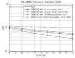
도 18은 본 발명의 제2 실시예에 따른 시뮬레이션 결과를 도시한 도면.1 is a diagram illustrating a structure of a 2x2 MIMO transmitter in an HSPA system,
2 is a diagram illustrating an equalization process of a channel and a receiver between a transmitter and a receiver in a 2x2 MIMO transmitter in an HSPA system,
3 is a scatter plot showing the output of the LMMSE equalizer when there is interference between the transmitted signals,
4 is a scatter plot showing the output of the LMMSE equalizer when there is no interference between the transmitted signals,
5 is a diagram illustrating a configuration of an LMMSE equalizer in a receiver of a 2x2 MIMO transmission / reception system according to the first embodiment of the present invention,
6 is a diagram for explaining the configuration of the interference
FIG. 7 is a view for explaining an equalization method in a receiver according to the first embodiment of the present invention, FIG.
8 is a diagram specifically explaining
9 is a diagram for explaining the contribution of each constellation point to a nonlinear MMSE estimation value in a constellation diagram of a 16-QAM modulation scheme;
FIG. 10 is a view for explaining a result of approximating an exponential function using a Taylor series,
11 is a view for explaining a method of dividing an exponential function by intervals in order to approximate an exponential function by a linear function according to the first embodiment of the present invention,
12 is a diagram illustrating a process of determining an approximated linear function for an exponential function in a corresponding section according to the first embodiment of the present invention;
13 is a diagram for explaining a tree structure of an OVSF code which is a channelization code of a WCDMA downlink,
14 is a diagram for explaining the configuration of an LMMSE equalizer in a receiver of a 2x2 MIMO transmission / reception system according to a second embodiment of the present invention
FIG. 15 is a diagram for explaining the configuration of the HS channel signal processing section 1421 of FIG. 14
FIG. 16 is a diagram for explaining the configuration of the non-HS channel
17 is a view for explaining the equalization method according to the second embodiment of the present invention,
18 shows simulation results according to the second embodiment of the present invention.
이하에서 본 발명의 바람직한 실시 예들을 첨부한 도면을 참조하여 상세히 설명한다. 도면들 중 동일한 구성 요소들은 가능한 한 어느 곳에서든지 동일한 부호들로 나타내고 있음에 유의해야 한다. 또한 본 발명의 요지를 불필요하게 흐릴 수 있는 공지 기능 및 구성에 대한 상세한 설명 생략한다.Hereinafter, preferred embodiments of the present invention will be described in detail with reference to the accompanying drawings. It is to be noted that the same elements among the drawings are denoted by the same reference numerals whenever possible. Further, the detailed description of known functions and configurations that may unnecessarily obscure the gist of the present invention will be omitted.
한편, 이하의 설명에서 신호 처리에 대한 설명은 시간 영역 신호라는 특별한 설명이 없는 한 주파수 영역의 신호를 기준으로 설명한다. 다만, 이는 설명의 편의를 위한 것일 뿐, 본 발명의 신호 처리는 주파수 영역 또는 시간 영역에서 수행될 수 있다.In the following description of the signal processing, a signal in the frequency domain is used as a reference, unless otherwise specified as a time domain signal. However, this is only for convenience of explanation, and the signal processing of the present invention can be performed in the frequency domain or the time domain.
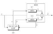
도 1은 HSPA 시스템에서 2x2 MIMO 송신기의 구조를 설명하는 도면이다.1 is a diagram illustrating a structure of a 2x2 MIMO transmitter in an HSPA system.
도 1을 참조하면, 두 개의 독립적인 전송 채널 프로세싱(transport channel processing)(101, 103)을 거친 각 데이터는 확산(spreading) 및 스크램블링(scrambling)(103, 104)을 거친 후에 프리코딩 매트릭스(precoding matrix)에 따른 가중치(weight)가 곱해진다. 상기 가중치는 가중치 생성기(120)에서 생성되며, 프리코딩 매트릭스는 <수학식 1>로 정의되어 있다.Referring to FIG. 1, each data through two independent

참고로, 상기 <수학식 1>에서 w는 네 종류의 값을 가질 수 있는데, 수신기에서 채널과 모든 가능한 프리코딩 매트릭스(precoding matrix)의 조합으로 이루어진 네 가지 신호 중 가장 큰 에너지를 가지는 프리코딩 매트릭스를 선택하고, 수신기는 상기 선택한 프리코딩 매트릭스를 송신기로 전송하도록 HSPA 표준에 정의되어 있다.In Equation (1), w may have four kinds of values. In a receiver, a precoding matrix having the largest energy among four signals, which is a combination of a channel and all possible precoding matrices, And the receiver is defined in the HSPA standard to transmit the selected precoding matrix to the transmitter.
상기 프리코딩을 거친 신호들은, 합산기(109, 110)에서 엇갈려 합산되고, 송신 안테나(113, 114)를 통하여 총 네 개의 무선 채널을 겪으면서 수신기로 송신된다. 이하에서 송신기 및 수신기 간의 채널과 수신기의 등화 과정에 대하여 설명한다.The pre-coded signals are summed by the
도 2는 HSPA시스템에서 2x2 MIMO 송신기에서 송신기 및 수신기 간의 채널과 수신기의 등화 과정 설명하는 도면이다.FIG. 2 is a diagram for explaining an equalization process of a channel and a receiver between a transmitter and a receiver in a 2x2 MIMO transmitter in an HSPA system.
도 2를 참조하면, 송신기(200)로부터 출력된 독립적인 송신 신호인 X1, X2는 송신 안테나 1(201)과 송신 안테나 2(202)를 통하여 출력되고, 채널 행렬 H로 표현되는 무선 채널을 통하여 수신기(210)로 송신된다.2, independent transmission signals X1 and X2 output from the
채널 행렬 H는 H1, H2, H3, H4로 구성되며, 상기 H1은 송신 안테나 1(201)과 수신 안테나 1(214) 간의 채널을 의미하고, H2는 송신 안테나 1(201)과 수신 안테나 2(215) 간의 채널을 의미하고, H3는 송신 안테나 2(202)와 수신 안테나 1(214) 간의 채널을 의미하며, H4는 송신 안테나 송신 안테나 2(202)와 수신 안테나 2(215) 간의 채널을 의미한다.The channel matrix H is composed of H1 , H2 , H3 and H4 , H1 denotes a channel between the
수신기(210)는 수신 안테나 1(214) 및 수신 안테나 2(215)를 통하여 신호 Y1, Y2를 각각 수신하고 상기 수신 신호 Y1, Y2는 LMMSE 등화기(111)와 MIMO 복호기(113)를 포함하는 수신기로 입력된다.The
상기 도 2에서 수신 신호 Y1, Y2는 하기 <수학식 2>로 표현될 수 있다.2, the received signals Y1 and Y2 may be expressed by Equation (2).

상기 N1은 수신 신호 Y1에서의 잡음 신호를 의미하고, 상기 N2는 수신 신호 Y2에서의 잡음 신호를 의미한다.N1 denotes a noise signal in the received signal Y1 , and N2 denotes a noise signal in the received signal Y2 .
상기 <수학식 2>를 이산 시간(Discrete-time) 신호로 표현하면, 하기 <수학식 3>으로 표현된다.Equation (2) can be expressed as a discrete-time signal, which is expressed by Equation (3) below.

한편, 수신기(210)의 LMMSE 등화기(211)는 수신 신호와 원하는 신호(desired signal)간의 상호 상관(cross-correlation)과 수신 신호간의 자기 상관(auto-correlation)을 이용하여 송신 신호를 추정하여 출력한다.Meanwhile, the LMMSE
구체적으로, LMMSE 등화기(111)는 송신 신호와 등화기 출력 신호 간의 평균 자승오차(mean square error; MSE)를 최소화(minimize)할 수 있도록 설계되며 이때 MSE는 <수학식 4>와 같이 정의된다.Specifically, the LMMSE equalizer 111 is designed to minimize the mean square error (MSE) between the transmission signal and the equalizer output signal, and the MSE is defined as Equation (4) .

상기 <수학식 4>를 만족시키는 MMSE 가중치(weight)는 하기 <수학식 5>와 같이 상호 상관(cross-correlation)과 자기 상관(auto-correlation) 역행렬의 곱으로 표현된다.The MMSE weight that satisfies Equation (4) is expressed as a product of a cross-correlation and an auto-correlation inverse matrix as shown in Equation (5).

따라서 2x2 MIMO 시스템에서 등화기의 출력은 하기 <수학식 6>와 같이 표현된다.Therefore, in the 2x2 MIMO system, the output of the equalizer is expressed as Equation (6).

한편, 상기 종래의 LMMSE 등화기의 출력(


그런데 일반적으로 이동 통신 환경에서 송수신기 사이의 거리에 비하여 MIMO 송신 안테나 간의 간격이 현저히 작은 경우가 대부분이다. 이 경우 평면파 이론에 의할 때 각 송신 안테나에서 출력된 신호가 경험하는 채널은 평면파의 입사각에 따른 위상 차이만 있을 뿐 동일한 것으로 알려져 있다. 이 같이 송신 안테나의 출력 신호가 경험하는 채널이 동일한 현상은 수신 안테나간 상관(correlation)이 높은 경우에도 발생할 수 있다.However, in most cases, the interval between MIMO transmission antennas is much smaller than the distance between the transceivers in a mobile communication environment. In this case, according to the plane wave theory, it is known that the channel experienced by the signal outputted from each transmitting antenna is only the phase difference according to the incident angle of the plane wave. The same phenomenon of the channel experienced by the output signal of the transmission antenna may occur even when the correlation between the reception antennas is high.
결국 이러한 환경에서 H1 채널과 H2 채널은 거의 동일하고, H3 채널과 H4 채널 값은 거의 동일한 것으로 볼 수 있다. 따라서 상기 <수학식 2>는 하기 <수학식 7>로 표현될 수 있다.As a result, in this environment, the H1 and H2 channels are almost identical, and the H3 and H4 values are almost the same. Therefore, Equation (2) can be expressed as Equation (7).

이렇게 H1 채널과 H2 채널이 거의 동일하고, H3 채널과 H4 채널이 거의 동일한 환경 하에서, LMMSE의 자기 상관(autocorrelation)행렬의 반전 (inversion)은 큰 오차를 갖게 되고, 따라서 MMSE를 이용한 등화의 출력 신호의 오류율(error rate) 역시 매우 커진다. 따라서 송신 신호 상호 간 간섭이 있는 경우의 LMMSE 등화기 출력 신호는 상호 간 간섭이 없는 경우 LMMSE 등화기 출력 신호보다 송신 신호의 추정에 오차가 매우 커진다.In this way, the inversion of the autocorrelation matrix of the LMMSE has a large error under the circumstances where the H1 and H2 channels are almost the same, and the H3 and H4 channels are substantially the same, The error rate of the output signal of the equalization becomes very large. Therefore, the LMMSE equalizer output signal in the presence of interfering transmission signals has a much larger error in estimating the transmission signal than the LMMSE equalizer output signal in the absence of mutual interference.
도 3은 송신 신호들 상호 간 간섭이 있을 때 LMMSE 등화기의 출력을 도시한 산점도(scatter plot)이고, 도 4는 송신 신호들 상호 간 간섭이 없을 때 LMMSE 등화기의 출력을 도시한 산점도(scatter plot)이다. 도 4가 도 3보다 송신 신호의 추정에 오차가 적음을 보여준다. 따라서 LMMSE 등화기 출력의 오율을 감소시키기 위하여 스트림 간 간섭을 제거 또는 감소시킬 필요가 있다.FIG. 3 is a scatter plot showing the output of the LMMSE equalizer when there is interference between the transmitted signals, FIG. 4 is a scatter plot showing the output of the LMMSE equalizer when there is no interference between the transmitted signals, plot. Fig. 4 shows that there is less error in estimating the transmission signal than Fig. Therefore, it is necessary to eliminate or reduce inter-stream interference in order to reduce the error rate of the LMMSE equalizer output.
<제1 실시예>≪
본 발명의 제1 실시예는 이러한 필요에 따라 상호 간 간섭이 제거된 수신 신호를 생성하고 이를 등화에 이용한다. 본 발명의 제1 실시예의 기본 개념을 간략히 설명한다.The first embodiment of the present invention generates a received signal from which interference between each other is eliminated according to the necessity and uses it for equalization. The basic concept of the first embodiment of the present invention will be briefly described.
본 발명의 제1 실시예는 상기 <수학식 7>에서 수신 신호를 등화하여 송신 신호를 추정하고, 상기 추정된 송신 신호를 이용하여 상기 수신 신호로부터 간섭이 제거된 복수 개의 수신 신호들을 생성하고, 상기 간섭이 제거된 복수 개의 수신 신호들을 독립적으로 등화하고, 이를 결합(combining)하여 간섭이 제거된 송신 신호를 추정한다. 즉, 간섭이 제거된 수신 신호들을 생성하고 이를 등화하여 가산하는 방식으로 높은 신뢰도를 가지는 송신 신호를 추정하는 동시에 다이버시티(diversity) 이득을 얻을 수 있다. 한편, 이러한 과정을 반복적으로 수행하면 수신 신호의 품질을 추가적으로 향상시킬 수 있다.The first embodiment of the present invention estimates a transmission signal by equalizing a reception signal in Equation (7), generates a plurality of reception signals from which interference is removed from the reception signal by using the estimated transmission signal, Estimates a transmission signal from which the interference is removed by independently equalizing the plurality of reception signals from which the interference is removed, and combining the signals. That is, a diversity gain can be obtained while estimating a transmission signal with high reliability by generating reception signals from which interference is removed, equalizing the signals, and adding the signals. On the other hand, if this process is repeatedly performed, the quality of the received signal can be further improved.
이하의 본 발명의 설명은 2X2 MIMO 송수신 시스템을 예로 하여 설명하고 있으나, 이는 설명의 편의를 위한 것일 뿐 2X2 이외의 다른 다중 송수신 시스템에서 동일하게 적용될 수 있다.The following description of the present invention is based on a 2X2 MIMO transmission / reception system. However, the present invention is not limited to the 2X2 MIMO transmission / reception system.
도 5는 본 발명의 제1 실시예에 따른 2X2 MIMO 송수신 시스템의 수신기에서 LMMSE 등화기의 구성을 설명하는 도면이다.5 is a diagram illustrating a configuration of an LMMSE equalizer in a receiver of a 2x2 MIMO transmission / reception system according to the first embodiment of the present invention.
본 발명의 등화기(500)는 등화부(510)와 간섭 제거 신호 생성부(520)를 포함한다.The equalizer 500 of the present invention includes an
도 5에서 입력 신호 Y는 2개의 안테나에서 수신된 (Y1, Y2)로 구성된다. 또한, 간섭 제거 신호 생성부(520)의 출력 Y', Y''은 각각 (Y1', Y2')과 (Y1'', Y2'')로 구성된다. 또한, 제1 LMMSE 등화기(511)의 출력


수신 신호 Y는 등화부(510)와 간섭 제거 신호 생성부(520)로 입력된다.The received signal Y is input to the
등화부(510)는 제1 LMMSE 등화기(511) 또는 제2 LMMSE 등화기(513) 중 하나를 이용하여 상기 수신 신호 Y를 등화하여 송신 신호를 추정하고, 상기 추정된 송신 신호(
상기 간섭 제거 신호 생성부(520)는 수신 신호 Y에서 상기 추정된 송신 신호(


이후, 상기


상기 Y'은 하기 <수학식 8>로 표현되고, 상기 Y''은 <수학식 9>로 표현된다.The Y 'is expressed by Equation (8) and the Y' is expressed by Equation (9).


한편, LMMSE에서 추정된 송신 신호는 원래 송신 신호의 감쇠 형태로 나타나므로 상기 <수학식 8> 및 <수학식 9>를 행렬-벡터 모델로 다시 표현하면 <수학식 10>으로 표현된다.Meanwhile, since the transmission signal estimated by the LMMSE is originally represented in an attenuated form of the transmission signal, Expression (8) and Expression (9) are expressed by a matrix-vector model.

상기 <수학식 10>에서 유의할 점은 송신 신호의 감쇠를 채널 행렬의 감쇠로 치환하여 표현한 것이다. 상기 <수학식 10>에 따라 간섭이 제거된 후의 등화기의 필터 계수를 다시 설계하면 등화의 성능을 높일 수 있다.In Equation (10), the attenuation of the transmission signal is replaced with the attenuation of the channel matrix. Equalization performance can be improved by redesigning the filter coefficient of the equalizer after interference is removed according to Equation (10).
한편, 상기 Y'를 등화한 결과 및 Y''를 등화 결과는 하기 <수학식 11>을 기초로 하여 표현된다. 즉, 하기 <수학식 11>에서 Y를 Y'으로, Y1을 Y1', Y2를 Y2'으로 치환하고,


도 6은 도 5의 간섭 제거 신호 생성부(520)의 구성을 설명하는 도면이다.FIG. 6 is a diagram for explaining the configuration of the interference
간섭 제거 처리부(520)는 심볼 생성부(610), 심볼 클리닝부(620), 가상 송신부(630), 가상 채널부(640)와 간섭 제거 처리부(650)를 포함한다.The interference
심볼 생성부(610)는 간섭 제거 신호 생성부(520)로부터 전달된 추정된 송신 신호


상기 심볼 생성부(610)에서 생성된 심볼은 코드채널의 이득(g)과 심볼(s)이 곱해진 형태로, 하기 <수학식 12>와 같이 표현된다.The symbol generated by the

심볼 클리닝부(620)는 상기 생성된 심볼에 대해서 심볼 클리닝을 수행하여 상기 심볼 생성부(610)에서 생성된 심볼보다 더 신뢰성 있는 심볼을 생성할 수 있다. 본 발명의 제1 실시예에서는 심볼 클리닝을 효율적으로 수행하기 위한 방식을 제안하는데, 이에 대해서는 도 9 이하에서 후술하기로 한다.The
가상 송신부(630)는 상기 클리닝이 수행된 심볼에 상기 도 1의 송신기의 신호 처리 절차를 적용한다. 즉, 심볼에 대하여 확산 및 스크램블링을 수행한 이후, 프리코딩 매트릭스를 곱한다. 상기 확산은 하다마드(Hadamard) 변환을 통하여 수행될 수 있고, 상기 스크램블링은 PN 코드를 곱하여 수행되는 것이 일반적이다.The
한편, 가상 채널부(640)는 상기 가상 송신부(630)의 출력 신호가 송신기(200)와 수신기(210) 간의 채널(H)을 경험하도록 하기 위하여, 상기 가상 송신부(630)의 출력 신호에 채널 함수를 곱한다. 만일 신호가 시간 영역에서 처리되는 경우라면 채널 함수의 컨벌루션이 수행될 것이다.The
간섭 제거 처리부(650)는 상기 수신 신호(Y)에서 상기 가상 채널부(640)부의 출력 신호를 이용하여 상기 <수학식 8>의 Y'과 및 <수학식 9>의 Y''을 출력하여 송신 신호 상호 간의 간섭이 제거된 신뢰도 높은 수신 신호들을 생성한다. 이후 상기 Y'과 Y''는 도 5에서 설명된 바와 같이 등화부(510)로 입력되어 독립적으로 등화된 이후, 선형 가산 되어
한편, 상기 심볼 생성부(610), 심볼 클리닝부(620), 가상 송신부(630)는 등화부(510)에서 등화되어 추정된 송신 신호(

도 7은 본 발명의 제1 실시예에 따른 수신기에서 등화 방법을 설명하는 도면이다.7 is a view for explaining an equalization method in a receiver according to the first embodiment of the present invention.
701단계에서 수신기가 송신기로부터 송신된 신호(Y)를 수신하면, 703단계에서 등화부(510)는 상기 수신 신호를 등화하여 송신 신호를 추정하여(
705단계에서 간섭 제거 신호 생성부(520)는 상기 추정된 송신 신호를 이용하여 송신 신호 상호 간 간섭이 제거된 수신 신호(Y', Y'')를 생성한다.In
707단계에서 등화부(510)는 상기 Y'과 Y''를 독립적으로 등화하여


도 8은 도 7의 705 단계를 구체적으로 설명한 도면이다.FIG. 8 is a diagram specifically illustrating
801단계에서 심볼 생성부(610)는 간섭 제거 신호 생성부(520)로부터 전달된 추정된 송신 신호(


803단계에서 심볼 클리닝부(620)는 상기 생성된 심볼에 대해서 심볼 클리닝을 수행하여 상기 심볼 생성부(620)에서 생성된 심볼보다 더 신뢰성 있는 심볼을 생성할 수 있다. 본 발명은 심볼 클리닝을 효율적으로 수행하기 위한 방식을 제안하는데, 이에 대해서는 도 9 이하에서 후술하기로 한다.In
805단계에서 가상 송신부(630)는 상기 클리닝이 수행된 심볼에 상기 도 1의 송신기의 신호 처리 절차를 적용한다. 즉, 심볼에 대하여 확산 및 스크램블링을 수행한 이후, 프리코딩 매트릭스를 곱한다. 상기 확산은 하다마드(Hadamard) 변환을 통하여 수행될 수 있고, 상기 스크램블링은 PN 코드를 곱하여 수행되는 것이 일반적이다.In
807단계에서 가상 채널부(640)는 상기 가상 송신부(630)의 출력 신호가 송신기(200)와 수신기(210) 간의 채널(H)을 경험하도록 하기 위하여, 상기 가상 송신부(630)의 출력 신호에 채널 함수를 곱하여 채널을 적용한다.The
809단계에서는 상기 채널이 적용된 심볼을 이용하여 상기 수신 신호(Y)에서 송신 신호 상호 간의 간섭이 제거된 신호들(Y', Y'')을 생성한다.In
한편, 상기 801단계 내지 805단계는 등화부(510)에서 등화되어 추정된 송신 신호(

이하에서는 상기 도 6에서 언급된 본 발명의 제1 실시예에서 제안하는 심볼 클리닝 방식을 설명한다.Hereinafter, the symbol cleaning method proposed in the first embodiment of the present invention will be described with reference to FIG.
통상 심볼 클리닝은 소프트 슬라이싱(soft slicing)으로 칭해지기도 하며, 이하에서는 동일한 의미로 혼용될 수 있다. 상기 소프트 슬라이싱 방식은 보통 선형(Linear) MMSE 방식과 일반적인, 즉, 비선형(Non Linear) MMSE 방식이 사용된다.In general, symbol cleaning may be referred to as soft slicing, and may be used interchangeably in the following description. The soft slicing method is generally a linear MMSE method, that is, a non-linear MMSE method is used.
상기 선형 MMSE 방식을 이용한 소프트 슬라이싱의 결과는 <수학식 13>으로 표현되는 것으로 알려져 있고, 비선형 MMSE 방식을 이용한 소프트 슬라이싱의 결과는 <수학식 14>로 표현되는 것으로 알려져 있다.The result of the soft slicing using the linear MMSE scheme is known to be expressed by Equation (13), and the result of soft slicing using the nonlinear MMSE scheme is known to be expressed by Equation (14).


한편, 상기 <수학식 14>를 다시 정리하면 하기 <수학식 15>로 표현될 수 있다.The above Equation (14) can be rewritten as Equation (15).

상기 <수학식 15>를 참조하면, 비선형 MMSE 방식의 소프트 슬라이싱을 구현하기 위해서는 지수(exponential) 함수를 구현하는 것이 필요하다. 그런데 지수 함수를 하드웨어적으로 구현하기에는 매우 복잡해지는 문제가 있다. 따라서 본 발명에서는 지수 함수를 하드웨어적으로 구현하기 용이한 구분(piecewise) 선형 함수로 근사화하는 방식을 제안한다. Referring to Equation (15), it is necessary to implement an exponential function in order to implement the non-linear MMSE soft slicing. However, it is very complicated to implement the exponential function in hardware. Therefore, the present invention proposes a method of approximating an exponential function with a piecewise linear function that is easy to implement in hardware.
심볼 클리닝, 즉, 소프트 슬라이싱을 하는 이유는 심볼 생성부(610)에서 생성된 심볼의 신뢰성을 더 높이기 위함이다. 한편, 비선형 MMSE 방식은 성상도 상의 모든 성좌점(constellation point)들의 선형 결합으로 표현될 수 있다. 한편, 이 때, 수신 심볼의 성상도 상의 위치에 따라 각각이 상기 <수학식 15>의 결과 값에 미치는 기여도(contribution)는 서로 다르다.The reason for performing the symbol cleaning, that is, the soft slicing, is to further increase the reliability of the symbol generated by the
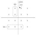
예를 들어, 도 9와 같이 16-QAM 변조 방식의 성상도에서 각 성좌점들의 비선형 MMSE 추정값에 대한 기여도는 시간 영역의 수신 신호 y(900)와 가까울수록 높고 멀리 떨어질수록 낮게 된다. 도 9에서 성좌점 901의 기여도가 가장 높고, 성좌점 903이 다음으로 기여도가 높고, 가장 멀리 떨어진 성좌점(905)들의 기여도가 낮음이 표시되어 있다.For example, as shown in FIG. 9, in the constellation diagram of the 16-QAM modulation scheme, the contribution of each constellation point to the nonlinear MMSE estimation value becomes lower as the distance to the received signal y (900) in the time domain increases. In FIG. 9, it is indicated that the contribution of the
한편, 지수 함수를 근사화할 때 가장 쉽게 생각할 수 있는 방식은 도 10에서 도시된 바와 같이 지수 함수를 테일러(Taylor) 급수를 이용하여 1차 근사화하거나, 또는 수신 신호로부터 가장 멀리 떨어져 있는 성좌점을 고려하지 않는 방식이 있다. 도 10의 참조 번호 1010, 1020, 1030 각각은 실제 지수 함수, 1차 테일러 급수를 이용한 근사화 결과, 2차 테일러 급수를 이용한 근사화의 결과를 표시한 것이다.On the other hand, the easiest way to approximate the exponential function is to first approximate the exponential function using a Taylor series as shown in FIG. 10, or to consider a constellation point farthest from the received signal There is a way not to.
상기 도 10에서 볼 수 있듯이, 상기 방식들을 시뮬레이션한 결과 상기 방식들은 원하는 방식대로 작동하지 않거나, 실제의 비선형 MMSE 함수를 사용할 때에 비하여 현저히 나쁜 결과를 나타낸다.As can be seen from the above FIG. 10, as a result of simulation of the schemes, the schemes do not operate the desired way or exhibit significantly worse results than when using the actual nonlinear MMSE function.
따라서 본 발명에서는 지수 함수를 근사화를 더 정확히 하기 위하여 지수 함수를 그 중요도에 따라 구간을 나누고, 상기 각 구간에 대해서 최적의 선형 함수로 표현하는 방식을 제안한다.Therefore, in order to more precisely approximate the exponential function, the present invention proposes a method of dividing the exponential function according to its importance and expressing the exponential function as an optimal linear function for each of the intervals.
본 발명에서는 지수 함수를 선형 함수로 근사화할 때의 오차를 최소화하기 위하여 지수 함수의 함수값의 크기에 따라 지수 함수의 구간의 크기를 다르게 설정한다. 이는 도 11을 참조하여 설명될 것이다.In the present invention, in order to minimize the error when the exponential function is approximated by the linear function, the size of the exponential function section is set differently according to the size of the function value of the exponential function. This will be described with reference to FIG.
또한, 상기 다르게 설정된 각 구간의 지수 함수로부터 선형 함수를 결정할 때에는, 해당 구간에서 실제 지수 함수의 시작점과 종료점에 의하여 결정되는 선형 함수를 적절히 평행 이동하여 최종적으로 근사화된 선형 함수를 결정한다. 상기 평행 이동은 상기 지수 함수와 상기 최종적으로 근사화된 선형 함수와의 평균 자승 오차(MSE)가 최소화될 조건을 만족하도록 설정한다. 즉, 상기 평행 이동은 MMSE를 만족하도록 결정된다. 이는 도 12를 참조하여 설명될 것이다.Also, when determining the linear function from the exponential function of each of the differently set intervals, the linear function determined by the starting point and the end point of the actual exponential function in the corresponding interval is appropriately translated in parallel to finally determine the approximated linear function. The parallel movement is set so as to satisfy a condition that a mean square error (MSE) between the exponential function and the finally approximated linear function is minimized. That is, the parallel movement is determined to satisfy the MMSE. This will be described with reference to FIG.
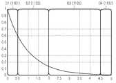
도 11은 본 발명의 실시예에 따라 지수(exponential) 함수를 선형 함수로 근사화하기 위하여 지수 함수를 구간 별로 구분하는 방식을 설명하는 도면이다.11 is a view for explaining a method of dividing an exponential function by intervals to approximate an exponential function with a linear function according to an embodiment of the present invention.
도 11을 참조하면, 지수 함수가 네 개의 구간, 즉, D1(1101), D2(1103), D3(1105), D4(1107)로 구분된 것을 볼 수 있다.Referring to FIG. 11, it can be seen that the exponential function is divided into four sections: D1 (1101), D2 (1103), D3 (1105), and D4 (1107).
첫 번째 구간 D1(1101)에서는 함수 값의 크기가 크기 때문에 구간의 간격을 좁게 설정하여 더 정확한 근사식을 얻을 수 있으며, 두 번째 구간 D2(1103)에서 함수 값이 D1(1101)보다 작기 때문에 구간의 간격을 D1(1101)보다 상대적으로 크도록 하였다. 따라서, 지수 함수의 값이 큰 경우에 상기 <수학식 15>에 따른 소프트 슬라이싱의 결과 값에 대한 더 정확한 함수를 얻을 수 있으며 결과적으로 비선형 MMSE 값도 더 정확해진다.Since the function value is large in the first period D1 (1101), a more accurate approximation formula can be obtained by narrowing the interval between the intervals. Since the function value in the
도 12는 본 발명의 제1 실시예에 따라 해당 구간에서 지수 함수에 대한 근사화된 선형 함수를 결정하는 과정을 설명하는 도면이다.12 is a diagram for explaining a process of determining an approximated linear function for an exponential function in a corresponding section according to the first embodiment of the present invention.
참조 번호 1201는 해당 구간에서 실제 지수 함수의 시작점과 종료점을 이용하여 선형 함수를 결정하는 포인트 매핑(point mapping)을 나타낸다. 상기 포인트 매핑(1201) 방식에 따라 선형 함수를 결정하면, 해당 선형 함수의 시작점과 종료점을 제외한 나머지 부분에서 오차가 매우 커지는 것을 볼 수 있다. 이는 전체적으로 선형 함수와 지수 함수와의 오차가 커지는 결과가 된다. 따라서 본 발명은 이러한 오차를 최소화하기 위하여 상기 포인트 매핑에 의하여 결정된 선형 함수가 MMSE 조건을 만족하는 선형 함수가 되도록 한다. 참조 번호 1203은 본 발명의 실시예에 따른 MMSE 조건이 충족되도록 선형 함수를 결정한 것을 나타낸다. 이하에서 MMSE 조건을 만족하도록 선형 함수를 결정하는 과정을 설명한다.
임의의 구간에서 지수 함수의 시작점과 종료점의 좌표를 각각 [x0, y0], [x1, y1] 이라고 할 때, 상기 [x0, y0], [x1, y1]을 시작점 및 종료점으로 하는 선형 함수는 하기 <수학식 16>으로 결정된다.The coordinates of the start point and end point of the exponential function at a specific interval, respectively [x0, y0], when it [x1, y1], the[x 0, y 0], [x 1, y 1] The linear function having the starting point and the ending point is determined by the following equation (16).

상기 <수학식 16>의 선형 함수에서 선형 함수와 지수 함수와의 오차가 최소화될 수 있도록 기울기 값 α와 y 절편 값 β를 결정하면 상기 선형 함수와 지수 함수와의 오차가 최소화될 것이다. 본 발명에서는 MSE(Mean Square Error)가 최소화되도록 상기 기울기 값 α와 y 절편 값 β 를 결정한다.If the slope value? And the y intercept value? Are determined so that the error between the linear function and the exponential function can be minimized in the linear function of Equation (16), the error between the linear function and the exponential function will be minimized. In the present invention, the slope value? And the y intercept value? Are determined so that the MSE (Mean Square Error) is minimized.
상기 α와 β값에 따른 MSB 는 하기 <수학식 17>및 <수학식 18>로 표현된다.The MSBs according to the values of? And? Are expressed by Equation (17) and Equation (18).


상기 <수학식 18>에 따라 <수학식 17>을 다시 정리하면 <수학식 19>와 같다.Equation (17) is rearranged according to Equation (18) as shown in Equation (19).

상기 <수학식 19>에서는 편의상 상기 <수학식 17>의 MSE(α, β)를 J(α, β)로 표기하였다. 한편, 상기 <수학식 19>의 J(α, β), 즉, MSE(α, β)가 최소화되는 α와 β를 찾기 위해서는 상기 <수학식 19>를 α와 β에 대하여 편미분한 값이 각각 0이 되는 α와 β값을 찾으면 된다. 이러한 과정은 하기 <수학식 20>으로 표현된다.In Equation (19), MSE (?,?) In Equation (17) is expressed as J (?,?) For convenience. In order to find α and β in which J (α, β), ie, MSE (α, β) in the above Equation (19) is minimized, the value obtained by partial differentiation of Equation (19) Find the values of alpha and beta that are zero. This process is expressed by Equation (20) below.

상기 <수학식 20>을 다시 정리하면 하기 <수학식 21>로 표현된다.The above Equation (20) can be rewritten as Equation (21).

상기 <수학식 21>에 따라 J(α, β), 즉, MSE(α, β)가 최소화되는 α와 β가 결정될 수 있다. 따라서 상기 결정된 α와 β에 따라 결정되는 선형 함수가 해당 구간의 지수 함수에 대한 최종 근사화된 선형 함수가 된다.According to Equation (21), α and β, in which J (α, β), ie, MSE (α, β) is minimized, can be determined. Therefore, the linear function determined according to the determined? And? Becomes the final approximated linear function of the exponential function of the corresponding section.
상술한 본 발명의 지수 함수 근사화 방식에 따라 지수 함수를 근사화하는 예를 설명한다. 만일 지수 함수의 구간을 6 단계로 구분하였다면 각 구간에서 근사화된 선형 함수는 하기 <수학식 22>로 표현된다An example of approximating an exponential function according to the exponential approximation method of the present invention will be described. If the interval of the exponential function is divided into 6 steps, the approximated linear function in each interval is expressed by Equation (22)

즉, 상기 <수학식 22>를 참조하면, 지수 함수의 값은 x가 증가하면 감소하므로 x가 증가할수록 해당 구간의 길이가 길어진 것을 볼 수 있다. 이렇게 구분된 구간들에서 각각의 지수 함수에 대한 선형 함수를 결정하기 위한 α, β 값은 상기 <수학식 21>에 의하여 결정된 것이다.That is, referring to Equation (22), the value of the exponential function decreases as x increases, so that the length of the corresponding interval increases as x increases. The values of [alpha] and [beta] for determining the linear function for each exponential function in the sections thus divided are determined by Equation (21).
이하에서는 상술한 바에 따라 본 발명의 등화 성능을 시뮬레이션 한 결과를 설명한다.Hereinafter, simulation results of the equalization performance of the present invention will be described.
시뮬레이션은 HSPA 2x2 MIMO 시스템 환경에서 수행되었으며, 시뮬레이션은 QPSK, 16-QAM, 64-QAM에 대해서 수행되었으며, 상기 심볼 클리닝, 즉, 심볼 슬라이싱 방식에 따른 등화 성능을 파악하기 위하여 소프트 슬라이싱은 선형 슬라이싱, 비선형 슬라이싱 유사 비선형(approximately nonlinear: aNL) 슬라이싱 방식을 사용하였다. 상기 유사 비선형 슬라이싱 방식은 지수 함수를 16개의 구간으로 구분하였다.The simulation was performed in the HSPA 2x2 MIMO system environment. The simulation was performed for QPSK, 16-QAM, and 64-QAM. To understand the symbol cleaning, i.e., the equalization performance according to the symbol slicing scheme, Nonlinear slicing (approximately nonlinear: aNL) slicing method was used. The pseudo nonlinear slicing method divides the exponential function into 16 sections.
시뮬레이션 결과 본 발명에서 제안된 등화기를 사용하면 종래의 LMMSE 등화기에 비하여, 약 2 ~ 3 dB 가량의 수신 이득을 얻을 수 있음을 확인하였다.Simulation results show that using the equalizer proposed in the present invention, a reception gain of about 2 to 3 dB can be obtained compared with the conventional LMMSE equalizer.
구체적으로 QPSK 변조 방식을 사용한 경우, 본 발명에 따라 간섭 신호가 제거된 수신 신호를 등화하고, 소프트 슬라이싱 시 상기 선형 함수 근사화 방식을 사용한 경우 약 2.5 dB의 성능 개선을 확인하였고, 소프트 슬라이싱 시 비선형 슬라이싱 방식 또는 유사 비선형 슬라이싱 방식을 사용할 경우에 추가적인 2dB의 이득을 확인하였다.Specifically, when the QPSK modulation scheme is used, the received signal from which the interference signal is removed according to the present invention is equalized, and when the linear function approximation method is used for soft slicing, a performance improvement of about 2.5 dB is confirmed. In soft slicing, And a gain of 2 dB is further confirmed when using a similar nonlinear slicing scheme.
한편, 16-QAM 변조를 사용한 경우, 본 발명에 따라 간섭 신호가 제거된 수신 신호를 등화하고, 소프트 슬라이싱 시 상기 선형 함수 근사화 방식을 사용한 경우 약 2 dB의 성능 개선을 확인하였고, 소프트 슬라이싱 시 비선형 슬라이싱 방식 또는 유사 비선형 슬라이싱 방식을 사용할 경우에 3dB의 이득을 확인하였다.On the other hand, in the case of using 16-QAM modulation, the received signal from which the interference signal is removed according to the present invention is equalized, and when the linear function approximation method is used for soft slicing, a performance improvement of about 2 dB is confirmed. A gain of 3 dB was confirmed when a slicing method or a similar nonlinear slicing method was used.
또한, 64-QAM 변조를 사용한 경우, 본 발명에 따라 간섭 신호가 제거된 수신 신호를 등화하고, 소프트 슬라이싱 시 상기 선형 함수 근사화 방식을 사용한 경우 약 2 dB의 성능 개선을 확인하였고, 소프트 슬라이싱 시 비선형 슬라이싱 방식 또는 유사 비선형 슬라이싱 방식을 사용할 경우에 추가적인 2dB의 이득을 확인하였다.
In addition, when 64-QAM modulation is used, the received signal with the interference signal removed according to the present invention is equalized, and when the linear function approximation method is used for soft slicing, a performance improvement of about 2 dB is confirmed. An additional 2 dB gain was observed when using a slicing scheme or a similar nonlinear slicing scheme.
<제2 실시예>≪
이하에서 설명하는 본 발명의 제2 실시예는 상기 제1 실시예에서 제안한 간섭 제거를 이용한 등화 방식을 HS 채널(HS-PDSCH) 신호와 비(non)-HS 채널에 각각 별도로 적용하여 성능을 더욱 향상시킨 것이다.In the second embodiment of the present invention described below, the equalization scheme using the interference cancellation proposed in the first embodiment is separately applied to the HS channel (HS-PDSCH) signal and the non-HS channel, .
상기 "HS 채널"이란 3GPP Release 7 이후에서 정의된 HSDPA 데이터채널(HS-PDSCH)을 말한다. HS 데이터 채널은 확산 계수(Spreading Factor: SF)로서 16을 고정하여 사용한다. 한편, 변조 방식으로는 QPSK, 16QAM, 64QAM 등이 사용될 수 있다. 또한 2x2 다중 안테나 시스템에서 HS채널에는 프리코딩 방식이 사용된다.The "HS channel" refers to an HSDPA data channel (HS-PDSCH) defined in 3GPP Release 7 or later. The HS data channel has a spreading factor (SF) of 16 fixed. On the other hand, as the modulation method, QPSK, 16QAM, 64QAM, and the like can be used. In a 2x2 multi-antenna system, a precoding scheme is used for the HS channel.
상기 비-HS채널은 파일롯 채널(CPICH)과, P-CCPCH, S-CCPCH 등과 같이 3GPP Release 99(R 99)에서 정의되는 제어 채널, HS 제어 채널(HS-SCCH) 및 R99 데이터 채널(DPCH)등을 포함한다. 상기 비HS 채널은 SF가 고정되지 않으며 최소 4부터 최대 256까지의 다양한 SF가 사용될 수 있다. 예를 들어, 파일롯 채널에는 SF 256이 사용되고, R99 제어 채널, R99 데이터 채널 및 HS 제어 채널에는 통상적으로 SF 128이 사용된다. 한편, 변조 방식은 QPSK로 고정되어 있다. 또한, 상기 비HS 채널에 대해서는 2x2 다중 안테나 시스템에서 상기 HS채널과 같이 프리코딩이 적용되지 않으며, 대신 공간 시간 송신 다이버시티(space-time transmit diversity: STTD)를 적용한다. 이를 위하여 송신측에서는 STTD 부호화를 하고, 수신측에서는 신호의 복원을 위하여 STTD 복호화 및 STTD 재부호화 과정이 필요하다.The non-HS channel includes a pilot channel (CPICH), a control channel defined in 3GPP Release 99 (R99) such as P-CCPCH and S-CCPCH, an HS control channel (HS- And the like. The non-HS channels are not fixed in SF, and various SFs of at least 4 up to 256 can be used. For example,
도 13은 WCDMA 하향 링크의 채널화 코드인 OVSF 코드의 트리 구조를 설명하는 도면이다.13 is a diagram for explaining a tree structure of an OVSF code which is a channelization code of a WCDMA downlink.
도 13에서 SF 16일 경우, OVSF코드의 SF 16 브랜치(branch)의 16개의 코드 채널을 Ch0, … , Ch15라 할 때, Ch0(1301)는 CPICH, PICH, AICH, PCCPCH, HS-SCCH(1303) 등에 할당된다. 따라서 Ch0(1301)은 HS 데이터 채널에 할당될 수 없다.13, the 16 code channels of the
반면, 나머지 15개의 채널들(1305)은 HS 채널에 할당되거나 또는 비-HS 채널에 할당될 수도 있다. 예를 들어, 현재 단말이 SF 16인 HS-DSCH 채널 신호를 수신하는 단말이고, 해당 단말은 SF 16개의 16개의 채널 중, Ch1~CH5를 할당받고, 나머지 CH6~CH15는 SF 128인 R99 데이터 채널 신호를 수신하는 다른 단말들에게 할당된 경우이다. 참고로 OVSF 코드는 상위 계층의 특정 코드(예를 들어, SF4의 0000)가 한 사용자에게 할당되어 사용되면, 해당 코드에서 분기된 트리의 하위 계층의 모든 코드들(예를 들어, SF 8의 00000000, SF 64의 0000....0000)은 더 이상 사용될 수 없다. 이는 OVSF 코드 트리 구조의 특성 상위 계층의 코드와 해당 코드에서 분기된 하위 계층의 코드 간에는 직교성이 유지되지 않기 때문이다. 마찬가지로 하위 계층의 코드가 먼저 사용되면 그 코드의 상위 계층의 코드는 모두 사용될 수 없다.On the other hand, the remaining fifteen
상술한 것처럼 SF 16을 이용하여 HS 채널 신호를 수신하는 경우, SF 16의 모든 코드 채널들이 SF 16을 사용하는 HS 채널에만 할당되는 것은 아니다. 그런데 상기 제1 실시예는 모든 코드 채널들이 HS 채널로 구성될 때에 최적의 성능을 발휘할 수 있다. 따라서 본 발명의 제2 실시예는 코드 채널들이 HS 채널 신호와 비HS 채널 신호를 모두 포함할 경우, 해당 코드 채널들이 어떠한 채널 신호인지를 결정하고, HS 채널이라면 HS 신호를 처리하도록 구성된 기능 블록에서 간섭을 제거하고, 비HS 채널이라면 비HS 채널을 처리하도록 구성된 기능 블록에서 간섭을 제거하도록 한다.When the HS channel signal is received using
이하에서 제2 실시예에 대하여 상세히 설명한다.Hereinafter, the second embodiment will be described in detail.
도 14는 본 발명의 제2 실시예에 따른 2X2 MIMO 송수신 시스템의 수신기에서 LMMSE 등화기의 구성을 설명하는 도면이다.FIG. 14 is a diagram illustrating a configuration of an LMMSE equalizer in a receiver of a 2 × 2 MIMO transmission / reception system according to a second embodiment of the present invention.
도 14는 도 5에서 설명된 제1 실시예에 따른 등화기의 구성을 변형한 것이다.Fig. 14 is a modification of the configuration of the equalizer according to the first embodiment described in Fig.
도 14의 등화기를 도 5의 등화기와 비교하면, 제1 실시예는 HS 채널을 처리하는 것으로 전제로 하기 때문에 간섭 제거 신호 생성부(520)에서 모든 HS 채널 신호를 처리하였다. 그러나 제2 실시예에서 HS 채널 신호와 비HS 채널 신호는 각각 별도의 블록에서 처리된다. 즉, HS 채널 신호 처리부(1421)는 HS 채널 신호를 처리하고 비HS 채널 신호 처리부(1425) 비HS 채널 신호를 처리한다.Comparing the equalizer of FIG. 14 with the equalizer of FIG. 5, it is assumed that the HS channel is processed in the first embodiment. Therefore, the interference
한편, 채널 결정부(1423)는 HS 채널 신호 처리부(1421)로부터 전달받은 심볼과 비HS 채널 신호 처리부(1425)로부터 전달받은 심볼을 이용하여 본 발명에서 제안하는 방식에 따라 해당 신호가 HS 채널 신호인지 비HS 채널 신호인지를 결정한다.Meanwhile, the
구체적인 동작은 다음과 같다.The concrete operation is as follows.
수신 신호(Y)는 등화부(1410)로 입력되고, 등화부(1410)에 포함된 제1 LMMSE(1411) 또는 제2 LMMSE(1413) 중 하나에서 등화되어 송신 신호를 추정한다. 추정된 송신 신호(
상기 HS 채널 신호 처리부(1421)는 상기 추정된 송신 신호(

상기 채널 결정부(1423)는 후술하는 방식에 따라 SF 16의 각 코드가 SF16을 사용하는 HS 채널 데이터에 할당되었는지, SF 128을 사용하는 비HS 채널 데이터에 할당되었는지를 결정한다. 채널이 결정되었으면 결정된 채널에 따라 결정된 코드별 채널 정보를 HS 채널 신호 처리부(1421) 또는 비HS 채널 신호 처리부(1425)로 전달한다. 즉, Ch1이 HS 채널이고, Ch2가 비HS 채널이라면 이 정보를 각각 HS 채널 신호 처리부(1421)과 비HS 신호 처리부(1425)로 전달한다.The
HS 채널 신호 처리부(1421) 및 비HS 채널 신호 처리부(1425)는 상기 전달된 코드 별 채널 정보에 따라 자신이 처리해야 하는 코드 별 데이터에 대하여 간섭이 제거된 신호를 생성한다.The HS channel signal processing unit 1421 and the non-HS channel
즉, HS 채널 신호 처리부(1421)는 해당 코드 별로 (YHS', YHS'') 신호를 생성하고 상기 생성된 (YHS', YHS'')는 등화부(1410)의 제1 LMMSE(1411)과 제2 LMMSE(1413)으로 입력된 이후 각각 독립적으로 등화되어


도 15는 도 14의 HS 채널 신호 처리부(1421)의 구성을 설명하는 도면이다. 도 14에서 HS 채널 신호 처리부(1421)의 구성은 도 6의 구성과 실질적으로 동일하다.FIG. 15 is a diagram for explaining the configuration of the HS channel signal processing section 1421 of FIG. 14, the configuration of the HS channel signal processing section 1421 is substantially the same as the configuration of FIG.
즉, HS 채널 신호 처리부(1421)는 심볼 생성부(1510), 심볼 클리닝부(1520), 가상 송신부(1530), 가상 채널부(1540)와 간섭 제거 처리부(1550)를 포함한다.That is, the HS channel signal processing unit 1421 includes a
심볼 생성부(1510)는 등화부(1410)로부터 전달된 추정된 송신 신호


상기 심볼 생성부(1510)에서 생성된 심볼은 심볼 클리닝부(1520) 채널 결정부(1423)로 전달되고, 상기 채널 결정부(1423)에서 후술되는 방식에 따라 해당 코드 채널의 신호가 HS 채널 신호로 결정된다면, 상기 생성된 심볼은 다시 심볼 클리닝부(1520)로 전달된다.The symbol generated by the
심볼 클리닝부(1520)는 상기 생성된 심볼에 대해서 심볼 클리닝을 수행하여 상기 심볼 생성부(1510)에서 생성된 심볼보다 더 신뢰성 있는 심볼을 생성할 수 있다. 심볼 클리닝 방식은 앞서 제1 실시예인 도 9에서 설명된 바와 같다.The
가상 송신부(1530)는 상기 클리닝이 수행된 심볼에 상기 도 1의 송신기의 신호 처리 절차를 적용한다. 즉, 심볼에 대하여 확산 및 스크램블링을 수행한 이후, 프리코딩 매트릭스를 곱한다. 상기 확산은 하다마드(Hadamard) 변환을 통하여 수행될 수 있고, 상기 스크램블링은 PN 코드를 곱하여 수행되는 것이 일반적이다.The
한편, 가상 채널부(1540)는 상기 가상 송신부(1530)의 출력 신호가 송신기(200)와 수신기(210) 간의 채널(H)을 경험하도록 하기 위하여, 상기 가상 송신부(630)의 출력 신호에 채널 함수를 곱한다. 만일 신호가 시간 영역에서 처리되는 경우라면 채널 함수의 컨벌루션이 수행될 것이다.The
간섭 제거 처리부(1550)는 상기 수신 신호(Y)에서 상기 가상 채널부(640)부의 출력 신호를 이용하여 YHS'과 YHS''을 출력하여 송신 신호 상호 간의 간섭이 제거된 신뢰도 높은 수신 신호들을 생성한다. 이후 상기 YHS'과 YHS''는 도 14의 등화부(1410)로 입력되어 독립적으로 등화된 이후, 선형 가산 되어
도 16은 도 14의 비HS 채널 신호 처리부(1425)의 구성을 설명하는 도면이다.FIG. 16 is a diagram for explaining the configuration of the non-HS channel
비HS 채널 신호 처리부(1621)는 심볼 생성부(1610), 심볼 클리닝부(1620), 가상 송신부(1630), 가상 채널부(1640)와 간섭 제거 처리부(1650)를 포함한다. 상기 구성들은 도 15에서 설명된 각각의 대응되는 구성과 거의 동일한 동작을 수행하므로 동일한 동작에 대한 설명은 생략한다.The non-HS channel signal processing unit 1621 includes a
다만, 도 15의 심볼 생성부(1510)에서는 역프리코딩 행렬을 곱하고, 역 스크램블링 및 역확산을 수행하지만, 도 16의 심볼 생성부(1610)에서는 STTD 복호화를 수행하고, 역 스크램블링 및 역확산을 수행하는 점에서 차이가 있다. 이러한 차이점은 상술한 바와 같이 다중 안테나 시스템에서 비HS 채널(R99 데이터 채널) 데이터에 대해서는 송신기에서 프리코딩을 수행하지 않고 STTD 부호화를 수행하기 때문에 수신기에서도 역 프리코딩을 대신 STTD 복호화를 수행한다. 상기 STTD 복호화 시 HSPA-MIMO 시스템 하에서는 비-HS채널이 SF 128을 사용하기 때문에 SF 128을 이용하면 비-HS채널 신호들을 검출할 수 있다. 다만, 예외적으로, 파일럿 채널은 SF 256에 기반하여 STTD 부호화 되어 있으므로 STTD 복화화 시에도 SF 256을 사용해야 한다.However, the
또한, 도 15의 가상 송신부(1530)에서는 심볼에 대하여 확산 및 스크램블링을 수행하고, 프리코딩 매트릭스를 곱하였지만, 도 16의 가상 송신부(1630)에서는 비HS 채널 신호를 처리하기 때문에 확산 및 스크램블링 이후 STTD 부호화를 수행한다.15, spreading and scrambling are performed on symbols, and multiplication is performed by a precoding matrix. However, since the
이하에서는 상기 채널 결정부(1423)에서 채널을 결정하는 방식을 설명한다.Hereinafter, a method for determining a channel in the
본 발명의 제2 실시예에서는 가설 테스트(hypothesis testing)를 수행한다. 첫 번째 가정은 송신기가 해당 코드를 이용하여 HS 채널(HS-PDSCH) 데이터를 송신한 경우이고, 두 번째 가정은 송신기가 해당 코드를 이용하여 비 HS 채널 데이터(예컨대 SF128짜리인 DPCH)를 송신한 경우를 가정한다.In the second embodiment of the present invention, hypothesis testing is performed. The first assumption is that the transmitter transmits HS channel (HS-PDSCH) data using the corresponding code, and the second assumption is that the transmitter transmits non-HS channel data (e.g., DPCH of SF128) using the code .
<가설 1><
송신기가 SF 16인 OVSF 코드를 이용하여 HS 채널 데이터를 송신하였다고 가정한다. SF 16 인 HS 채널 데이터의 수신 심볼은 코드채널의 이득(g)과 심볼(s)이 곱해지고 잡음(v)이 더해진 형태로, 하기 <수학식 23>과 같이 표현된다.It is assumed that the transmitter transmits HS channel data using the

먼저 상기 <가설 1>에 대하여 수신기가 SF 16인 OVSF 코드를 이용하여 신호를 수신하는 경우 복원 심볼의 전력은 아래와 같이 계산된다.First, when the receiver receives a signal using the
상기 <수학식 23>의 신호에 SF16인 해당 OVSF 코드가 곱해진 값(z)은 하기 <수학식 24>으로 표현된다.The value (z) obtained by multiplying the signal of Equation (23) by the corresponding OVSF code of SF16 is expressed by Equation (24).

상기 <수학식 24>에서 N은 SF의 값으로서 N=16이다.N in Equation (24) is N = 16 as the value of SF.
한편, 상기 <수학식 24>에서 신호 z의 제곱 평균은 하기 <수학식 25>로 표현된다.Meanwhile, the square mean of the signal z in Equation (24) is expressed by Equation (25).

다음으로 상기 <가설 1>에 대하여 수신기가 SF 128인 OVSF 코드를 이용하여 신호를 수신하는 경우 복원 심볼의 전력은 아래와 같이 계산된다.Next, regarding the
SF 16의 하나의 코드에서 분기된 SF 128의 코드는 총 8개이다. 따라서 8개의 심볼을 모두 합해진 전체 심볼을 고려한다. 한편, 상기 <수학식 23>의 신호에 SF 128인 해당 OVSF코드 8개가 각각 곱해진 후 합해진 신호 z는 하기 <수학식 26>으로 표현된다.There are a total of 8 codes of

한편, 상기 <수학식 26>에서 신호 z의 제곱 평균은 하기 <수학식 27>로 표현된다.In Equation (26), the square mean of the signal z is expressed by Equation (27).

상기 <수학식 27>에서 N1=128/16=8, N2=128이 된다.N1 = 128/16 = 8 and N2 = 128 in Equation (27).
한편, 대수의 법칙(Law of large number)에 의하여 8개의 각각 다른 (평균이 0인) 심볼 Si의 합은 평균이 0인 단일한 가우시안(Gaussian) 랜덤 변수로 근사화될 수 있으며, 이는 하기 <수학식 28>으로 표현될 수 있다.On the other hand, according to the Law of large number, the sum of eight different (summed zero) symbol Si can be approximated to a single Gaussian random variable with an average of 0, Can be expressed by Equation (28).

상기 <수학식 28>은 하기 <수학식 29>과 같은 가우시안(Gaussian) 랜덤 변수의 분포를 가진다.Equation (28) has a distribution of Gaussian random variables as shown in Equation (29).

상기 <가설 1>에 대한 두 가지 경우, 즉, 즉, 송신측이 SF 128을 이용하여 신호를 송신하고, 수신측이 SF 16을 사용한 경우와 SF 128을 사용한 각 경우의 신호 z의 제곱 평균 값인 <수학식 25>와 <수학식 27>을 비교하면, SF 128인 경우의 복원된 신호(z)의 제곱 평균값(즉, 전력값)이 SF 16인 경우의 값보다 작음을 알 수 있다. 또한, SF 128일 때의 제곱 평균값과 SF 16일 때의 제곱 평균 값의 비는 대략 SF의 비율의 역수(16/128=1/8)이 됨을 알 수 있다.The two cases of
<가설 2><
송신기가 SF 128인 OVSF 코드를 이용하여 비 HS 채널(DPCH) 데이터를 송신하였다고 가정한다. SF 128 인 HS 채널 데이터의 수신 심볼은 코드채널의 이득(g)과 심볼(s)이 곱해지고 잡음(v)이 더해진 형태로, 하기 <수학식 30>과 같이 표현된다.It is assumed that the transmitter transmits non-HS channel (DPCH) data using the

먼저 상기 <가설 2>에 대하여 수신기가 SF 128인 OVSF 코드를 이용하여 신호를 수신하는 경우 복원 심볼의 전력은 아래와 같이 계산된다.First, when the receiver receives the signal using the
상기 <수학식 30>의 신호에 SF16인 해당 OVSF 코드가 곱해진 값(z)은 하기 <수학식 31>으로 표현된다.The value (z) obtained by multiplying the signal of Equation (30) by the corresponding OVSF code of SF16 is expressed by Equation (31).

여기서 N=128이 된다.Where N = 128.
한편, 상기 <수학식 31>에서 신호 z의 제곱 평균은 하기 <수학식 32>로 표현된다.In Equation (31), the square mean of the signal z is expressed by Equation (32).

다음으로 상기 <가설 2>에 대하여 수신기가 SF 16인 OVSF 코드를 이용하여 신호를 수신하는 경우 복원 심볼의 전력은 아래와 같이 계산된다.Next, with respect to
심볼에 대하여 SF 16인 해당 OVSF 코드가 곱해진 값(z)은 하기 <수학식 33>으로 표현된다.The value (z) obtained by multiplying the symbol by the corresponding OVSF code of

상기 <수학식 33>에서 N1은 SF의 값으로서 N=16이다.In Equation (33), N1 is the value of SF and N = 16.
한편, 상기 <수학식 33>에서 신호 z의 제곱 평균은 하기 <수학식 34>로 표현된다.In Equation (33), the square mean of the signal z is expressed by Equation (34).

상기 <가설 2>에 대한 두 가지 경우, 즉, 송신측이 SF 128을 이용하여 신호를 송신하고, 수신측이 SF 128을 사용한 경우와 SF 16을 사용한 각 경우의 신호 z의 제곱 평균값인 <수학식 32>와 <수학식 34>를 비교하면, SF 128인 경우의 복원된 신호(z)의 잡음 전력이 SF 16에서의 잡음 전력보다 작음을 알 수 있다.In the two cases of the
상기 <가설 1> 및 <가설 2>의 결과를 다음과 같이 이용될 수 있다.The results of <
첫째, 송신측이 실제로 해당 채널을 SF 16을 이용하여 송신한 경우, 수신측이 SF 16을 이용하여 얻은 신호의 전력과, SF 128을 이용하여 얻은 신호의 전력의 비율(r)은 하기 <수학식 35>와 같다.First, when the transmitting side actually transmits the channel using the

상기 <수학식 35>에서 r값은 8보다 큰 값이다. 또한, 신호의 전력이 잡음의 전력보다 커지면 상기 r값은 8로 근사화할 수 있다.In Equation (35), the r value is greater than 8. Also, if the power of the signal is greater than the power of the noise, the r-value can be approximated to 8.
둘째, 송신측이 실제로 해당 채널을 SF 128을 이용하여 송신한 경우, 수신측이 SF 16을 이용하여 얻은 신호의 전력과, SF 128을 이용하여 얻은 신호의 전력의 비율(r)은 하기 <수학식 36>과 같다.Second, when the transmitting side actually transmits the channel using the

상기 <수학식 36>에서 r값은 1보다 약간 큰 값이다. 신호의 전력이 잡음의 전력보다 크면 r값은 1로 근사화할 수 있다.In Equation (36), the r value is a value slightly larger than one. If the power of the signal is greater than the power of the noise, the r-value can be approximated by 1.
r값은 1보다 약간 크며, 신호제곱이 잡음파워보다 클 때 r값은 1로 근사화할 수 있다.The r value is slightly greater than 1, and the r value can be approximated to 1 when the signal squared is greater than the noise power.
상술한 바에 따라 본 발명의 제2 실시예에서 해당 채널이 SF 16을 사용하는 채널인지 아니면 SF 128을 사용하는 채널인지를 결정하는 방식은 다음과 같다.In the second embodiment of the present invention, a method for determining whether a corresponding channel is a
즉, 각 SF 16의 브랜치에서 해당 SF 16 코드를 사용하여 수신한 신호의 전력값과, 해당 SF 16 브랜치에서 분기된 SF 128의 8개의 코드들을 사용하여 수신한 8개의 신호들의 전력의 합을 비교하고, 상기 비교 결과가 소정 기준값 초과이면 해당 채널은 SF 16을 사용하여 송신된 채널(즉,HS 채널) 신호이므로 해당 채널은 HS 채널로 결정하고, 상기 기준값을 초과하지 않는다면 해당 채널은 SF 128을 사용하여 송신된 채널(즉, R99 채널)로 결정한다.That is, the power value of the signal received using the corresponding
상술한 가설 테스트는 하기 <수학식 37>로 표현된다.The foregoing hypothesis test is expressed by Equation (37) below.

상기 <수학식 37>에서 상기 τ값은 시스템 설정에 따라 1과 8사이에서 적절하게 선택될 수 있는 값이다. 상기 <수학식 37>의 결과에 따라 SF 16의 16개의 채널 중 Ch0을 제외한 16개 코드 채널에 대하여 해당 채널이 HS 채널인지 비-HS채널인지를 결정한다.In Equation (37), the value of τ is a value that can be appropriately selected between 1 and 8 according to the system setting. According to the result of Equation (37), it is determined whether the corresponding channel is an HS channel or a non-HS channel for 16 code channels excluding Ch0 among 16 channels of SF16.
각각의 코드 채널에 각각에 대하여 HS 채널인지 비-HS채널인지가 결정되었다면, 결정된 채널에 대응하는 블록에서 심볼 생성 이후의 동작을 수행한다.If it is determined that each code channel is an HS channel or a non-HS channel for each channel, an operation after symbol generation is performed in a block corresponding to the determined channel.
예를 들어, Ch1 코드 채널이 HS 채널로 결정되었고, Ch2 코드 채널은 비HS 채널로 결정되었다면, Ch1 코드 채널의 신호에 대해서는 HS 신호 처리부(1421)에서 심볼 생성 이후의 일련의 블록들(즉, 심볼 클리닝(1520), 가상 송신부(1530), 가상 채널부(1540), 간섭 제거 처리부(1550))의 동작을 수행하여 코드 채널 신호에 대하여 간섭이 제거된 신호(YHS', YHS'')를 추정하여 출력한다. 반면, 비HS 신호 처리부(1425)는 Ch1 코드 채널에 대해서는 출력을 0으로 한다. 반면, Ch2 코드 채널의 신호에 대해서는 비HS 신호 처리부(1425)에서 심볼 생성 이후의 일련의 블록들(즉, 심볼 클리닝(1620), 가상 송신부(1630), 가상 채널부(1640), 간섭 제거 처리부(1650))의 동작을 수행하여 코드 채널 신호에 대하여 간섭이 제거된 신호(YN-HS', YN-HS'')를 추정하여 출력한다. 반면, HS 신호 처리부(1421)는 Ch2 코드 채널에 대해서는 출력을 0으로 한다.For example, if the Ch1 code channel is determined to be an HS channel and the Ch2 code channel is determined to be a non-HS channel, the HS signal processing unit 1421 may perform a series of blocks after the symbol generation (YHS ', YHS ''), which are obtained by removing interference from the code channel signal by performing the operations of the
이러한 방식으로 각각의 코드 채널의 채널을 결정하고, 상기 결정된 채널에 대응하는 신호 처리 블록에서 해당 코드 채널 신호의 간섭을 제거하는 방식으로 간섭이 제거된 신호를 생성하여 수신측에서 송신측의 송신 신호를 추정하게 된다.In this manner, the channel of each code channel is determined, and the interference canceled signal is removed from the code channel signal in the signal processing block corresponding to the determined channel, .
도 17은 본 발명의 제2 실시예에 따른 등화 방법을 설명하는 도면이다.17 is a view for explaining the equalization method according to the second embodiment of the present invention.
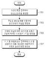
1701단계에서는 수신 신호를 등화하여 송신 신호를 추정하고, 1703단계에서는 상기 추정된 수신 신호를 이용하여 송신 신호의 채널을 결정한다. 1705단계에서는 상기 결정된 채널의 특성에 따라 별개의 신호 처리부를 이용하여 송신 신호 상호 간 간섭이 제거된 신호들을 생성하고, 1707단계에서는 상기 간섭이 제거된 신호들을 독립적으로 등화하고 등화한 결과값을 가산하여 최종적으로 추정된 송신 신호를 생성한다.In
도 18은 본 발명의 제2 실시예에 따른 시뮬레이션 결과를 도시한 도면이다. 또한, 상기 시뮬레이션 결과는 하기 <표 1>에 나타내었다.18 is a diagram showing a simulation result according to the second embodiment of the present invention. The results of the simulation are shown in Table 1 below.

상술한 바와 같이 제1 실시예는 HS-채널 신호 처리만을 포함하는 방식이고, 제2 실시예는 HS채널 신호와 비HS 채널 신호를 모두 포함하는 방식이며, 상기 <표 1>은 제2 실시예에 따른 실험 결과를 비교한 것이다. 도 18에서 볼 수 있듯이 제2 실시예의 두번째 반복(iteration)의 결과가 제1 실시예 두 번째 반복(iteration)의 결과보다 2dB 이상 성능이 향상되는 것을 볼 수 있다.As described above, the first embodiment includes only the HS-channel signal processing, and the second embodiment includes both the HS channel signal and the non-HS channel signal, To compare the experimental results. As shown in FIG. 18, it can be seen that the result of the second iteration of the second embodiment is improved by 2 dB or more than the result of the second iteration of the first embodiment.
한편, 제2 실시예의 경우 HS 채널 데이터와 비 HS 채널 데이터, 즉, R99 채널 및 제어 채널 데이터를 동시에 복원할 수 있기 때문에 사용하는 경우 스트림 간 간섭(interstream interference)를 효과적으로 제거할 수 있어 수신 성능을 크게 향상시킬 수 있다.On the other hand, in the case of the second embodiment, HS channel data and non-HS channel data, i.e., R99 channel and control channel data can be restored simultaneously, so that interstream interference can be effectively removed, Can greatly improve.
Claims (12)
Translated fromKorean수신 신호를 등화하여 송신 신호를 추정하는 과정;
상기 추정된 송신 신호가 상기 제1 채널 데이터인지 또는 제2 채널 데이터인지 여부를 결정하는 채널 결정 과정;
상기 추정된 송신 신호가 상기 제1 채널 데이터이면 상기 제1 채널의 특성에 따라 간섭을 제거하는 과정; 및
상기 추정된 송신 신호가 상기 제2 채널 데이터이면 상기 제2 채널의 특성에 따라 간섭을 제거하는 과정을 포함하고,
상기 채널 결정 과정은,
상기 추정된 송신 신호에 상기 제1 SF를 적용하여 생성한 심볼의 전력값과, 상기 추정된 송신 신호에 상기 제2 SF를 적용하여 생성한 심볼의 전력값의 비율을 소정 기준값과 비교하는 과정과,
상기 비교 결과 상기 비율이 상기 기준값을 초과하는 경우 상기 추정된 송신 신호를 상기 제1 채널 데이터로 결정하고, 상기 비율이 상기 기준값을 초과하지 않으면 상기 추정된 송신 신호를 상기 제2 채널 데이터로 결정하는 과정을 포함하는 방법.
A method for equalizing a received signal including at least one of first channel data spread using a first spreading factor (SF) and second channel data spread using a second spreading factor in a wireless communication system,
Estimating a transmission signal by equalizing the reception signal;
Determining whether the estimated transmission signal is the first channel data or the second channel data;
Removing interference according to the characteristics of the first channel if the estimated transmission signal is the first channel data; And
And canceling the interference according to the characteristics of the second channel if the estimated transmission signal is the second channel data,
The channel determination process includes:
Comparing a power value of a symbol generated by applying the first SF to the estimated transmission signal and a ratio of a power value of a symbol generated by applying the second SF to the estimated transmission signal to a predetermined reference value; ,
Determines the estimated transmission signal as the first channel data when the ratio exceeds the reference value, and determines the estimated transmission signal as the second channel data if the ratio does not exceed the reference value ≪ / RTI >
상기 제1 SF는 16이고, 상기 제1 채널은 HS 채널(HS-PDSCH)임을 특징으로 하는 방법.
The method according to claim 1,
Wherein the first SF is 16 and the first channel is an HS channel (HS-PDSCH).
상기 제1 채널 데이터의 송신기 신호 처리의 역 절차를 적용하여 심볼을 생성하는 과정;
상기 생성된 심볼을 클리닝하는 과정;
상기 클리닝된 심볼에 대하여 가상 송신 절차를 적용하는 과정;
상기 가상 송신 절차가 적용된 심볼에 상기 송신기와 수신기 간의 채널을 적용하는 과정과;
상기 채널이 적용된 심볼을 이용하여, 상기 수신 신호로부터 간섭이 제거된 복수 개의 수신 신호들을 생성하는 과정을 포함하는 방법.
4. The method of claim 3, wherein the removing the interference according to the characteristics of the first channel comprises:
Generating a symbol by applying a reverse procedure of the transmitter signal processing of the first channel data;
A step of clearing the generated symbol;
Applying a virtual transmission procedure to the cleaned symbol;
Applying a channel between the transmitter and the receiver to a symbol to which the virtual transmission procedure is applied;
And generating a plurality of reception signals from which interference is removed from the reception signal using the channel-applied symbols.
상기 제2 SF는 128이고, 상기 제1 채널은 R99 데이터(DTCH) 채널임을 특징으로 하는 방법.
The method according to claim 1,
The second SF is 128, and the first channel is a R99 data (DTCH) channel.
상기 제2 채널 데이터의 송신기 신호 처리의 역 절차를 적용하여 심볼을 생성하는 과정;
상기 생성된 심볼을 클리닝하는 과정;
상기 클리닝된 심볼에 대하여 가상 송신 절차를 적용하는 과정;
상기 가상 송신 절차가 적용된 심볼에 상기 송신기와 수신기 간의 채널을 적용하는 과정과;
상기 채널이 적용된 심볼을 이용하여, 상기 수신 신호로부터 간섭이 제거된 복수 개의 수신 신호들을 생성하는 과정을 포함하는 방법.
6. The method of claim 5, wherein the removing the interference according to the characteristics of the second channel comprises:
Generating a symbol by applying a reverse procedure of the transmitter signal processing of the second channel data;
A step of clearing the generated symbol;
Applying a virtual transmission procedure to the cleaned symbol;
Applying a channel between the transmitter and the receiver to a symbol to which the virtual transmission procedure is applied;
And generating a plurality of reception signals from which interference is removed from the reception signal using the channel-applied symbols.
수신 신호를 등화하여 송신 신호를 추정하는 등화부;
상기 추정된 송신 신호가 상기 제1 채널 데이터인지 또는 제2 채널 데이터인지 여부를 결정하는 채널 결정부;
상기 추정된 송신 신호가 상기 제1 채널 데이터이면 상기 제1 채널의 특성에 따라 간섭을 제거하는 제1 채널 신호 처리부; 및
상기 추정된 송신 신호가 상기 제2 채널 데이터이면 상기 제2 채널의 특성에 따라 간섭을 제거하는 제2 채널 신호 처리부를 포함하고,
상기 채널 결정부는,
상기 제1 채널 신호 처리부가 상기 추정된 송신 신호에 상기 제1 SF를 적용하여 생성한 심볼의 전력값과, 상기 제2 채널 신호 처리부가 상기 추정된 송신 신호에 상기 제2 SF를 적용하여 생성한 심볼의 전력값의 비율을 소정 기준값과 비교하고, 상기 비교 결과 상기 비율이 상기 기준값을 초과하는 경우 상기 추정된 송신 신호를 상기 제1 채널 데이터로 결정하고, 상기 비율이 상기 기준값을 초과하지 않으면 상기 추정된 송신 신호를 상기 제2 채널 데이터로 결정함을 특징으로 하는 장치.
An apparatus for equalizing a received signal including at least one of first channel data spread using a first spreading factor (SF) and second channel data spread using a second spreading factor in a wireless communication system,
An equalizer for equalizing a received signal to estimate a transmitted signal;
A channel determination unit for determining whether the estimated transmission signal is the first channel data or the second channel data;
A first channel signal processing unit for removing interference according to the characteristics of the first channel if the estimated transmission signal is the first channel data; And
And a second channel signal processor for removing interference according to the characteristics of the second channel if the estimated transmission signal is the second channel data,
Wherein the channel determination unit comprises:
Wherein the first channel signal processing unit is configured to calculate a power value of a symbol generated by applying the first SF to the estimated transmission signal and a power value of a symbol generated by applying the second SF to the estimated transmission signal Wherein the channel estimation unit determines the estimated transmission signal as the first channel data when the ratio exceeds the reference value and if the ratio does not exceed the reference value, And determines the estimated transmission signal as the second channel data.
상기 제1 SF는 16이고, 상기 제1 채널은 HS 채널(HS-PDSCH)임을 특징으로 하는 장치.
8. The method of claim 7,
Wherein the first SF is 16 and the first channel is an HS channel (HS-PDSCH).
상기 제1 채널 신호 처리부는,
상기 제1 채널 데이터의 송신기 신호 처리의 역 절차를 적용하여 심볼을 생성하는 심볼 생성부;
상기 생성된 심볼을 클리닝하는 심볼 클리닝부;
상기 클리닝된 심볼에 대하여 가상 송신 절차를 적용하는 가상 송신부;
상기 가상 송신 절차가 적용된 심볼에 상기 송신기와 수신기 간의 채널을 적용하는 가상 채널부; 및
상기 채널이 적용된 심볼을 이용하여, 상기 수신 신호로부터 간섭이 제거된 복수 개의 수신 신호들을 생성하는 과정을 간섭 제거 처리부를 포함하는 장치.
10. The method of claim 9,
Wherein the first channel signal processing unit comprises:
A symbol generator for generating a symbol by applying a reverse procedure of the transmitter signal processing of the first channel data;
A symbol cleaning unit for cleaning the generated symbol;
A virtual transmitter for applying a virtual transmission procedure to the cleaned symbol;
A virtual channel unit for applying a channel between the transmitter and the receiver to a symbol to which the virtual transmission procedure is applied; And
And an interference cancellation processing unit for generating a plurality of reception signals from which the interference is removed from the reception signal using the symbol to which the channel is applied.
상기 제2 SF는 128이고, 상기 제1 채널은 R99 데이터(DTCH) 채널임을 특징으로 하는 장치.
8. The method of claim 7,
The second SF is 128, and the first channel is a R99 data (DTCH) channel.
상기 제2 채널 데이터의 송신기 신호 처리의 역 절차를 적용하여 심볼을 생성하는 심볼 생성부;
상기 생성된 심볼을 클리닝하는 심볼 클리닝부;
상기 클리닝된 심볼에 대하여 가상 송신 절차를 적용하는 가상 송신부;
상기 가상 송신 절차가 적용된 심볼에 상기 송신기와 수신기 간의 채널을 적용하는 가상 채널부; 및
상기 채널이 적용된 심볼을 이용하여, 상기 수신 신호로부터 간섭이 제거된 복수 개의 수신 신호들을 생성하는 과정을 간섭 제거 처리부를 포함하는 장치.12. The apparatus of claim 11, wherein the second channel signal processor comprises:
A symbol generator for generating a symbol by applying an inverse procedure of the transmitter signal processing of the second channel data;
A symbol cleaning unit for cleaning the generated symbol;
A virtual transmitter for applying a virtual transmission procedure to the cleaned symbol;
A virtual channel unit for applying a channel between the transmitter and the receiver to a symbol to which the virtual transmission procedure is applied; And
And an interference cancellation processing unit for generating a plurality of reception signals from which the interference is removed from the reception signal using the symbol to which the channel is applied.
Priority Applications (2)
| Application Number | Priority Date | Filing Date | Title |
|---|---|---|---|
| KR1020110039011AKR101820915B1 (en) | 2011-04-26 | 2011-04-26 | Apparatus and method for equalizing a signal using canceling interference in a wiless communication system |
| US13/278,487US8724685B2 (en) | 2010-10-21 | 2011-10-21 | Apparatus and method for interference cancellation in MIMO wireless communication system |
Applications Claiming Priority (1)
| Application Number | Priority Date | Filing Date | Title |
|---|---|---|---|
| KR1020110039011AKR101820915B1 (en) | 2011-04-26 | 2011-04-26 | Apparatus and method for equalizing a signal using canceling interference in a wiless communication system |
Publications (2)
| Publication Number | Publication Date |
|---|---|
| KR20120121185A KR20120121185A (en) | 2012-11-05 |
| KR101820915B1true KR101820915B1 (en) | 2018-03-08 |
Family
ID=47507676
Family Applications (1)
| Application Number | Title | Priority Date | Filing Date |
|---|---|---|---|
| KR1020110039011AActiveKR101820915B1 (en) | 2010-10-21 | 2011-04-26 | Apparatus and method for equalizing a signal using canceling interference in a wiless communication system |
Country Status (1)
| Country | Link |
|---|---|
| KR (1) | KR101820915B1 (en) |
Families Citing this family (2)
| Publication number | Priority date | Publication date | Assignee | Title |
|---|---|---|---|---|
| KR101995160B1 (en)* | 2018-02-21 | 2019-07-02 | 한국과학기술원 | Wireless communication system allocating spreading coefficient to end device to accommodate massive end devices |
| CN115603776A (en)* | 2021-07-09 | 2023-01-13 | 中国移动通信集团重庆有限公司(Cn) | Signal processing method, device, equipment and medium |
Citations (2)
| Publication number | Priority date | Publication date | Assignee | Title |
|---|---|---|---|---|
| KR100351732B1 (en) | 2001-02-21 | 2002-09-12 | (주)파워코리아 | Blind/adaptive interference canceller and method, blind/adaptive interference cancellation apparatus, system and method used that |
| KR100816032B1 (en) | 2007-02-13 | 2008-03-24 | 삼성전자주식회사 | Method and apparatus for data transmission and reception through repetitive multi-user detection |
- 2011
- 2011-04-26KRKR1020110039011Apatent/KR101820915B1/enactiveActive
Patent Citations (2)
| Publication number | Priority date | Publication date | Assignee | Title |
|---|---|---|---|---|
| KR100351732B1 (en) | 2001-02-21 | 2002-09-12 | (주)파워코리아 | Blind/adaptive interference canceller and method, blind/adaptive interference cancellation apparatus, system and method used that |
| KR100816032B1 (en) | 2007-02-13 | 2008-03-24 | 삼성전자주식회사 | Method and apparatus for data transmission and reception through repetitive multi-user detection |
Also Published As
| Publication number | Publication date |
|---|---|
| KR20120121185A (en) | 2012-11-05 |
Similar Documents
| Publication | Publication Date | Title |
|---|---|---|
| EP2742601B1 (en) | Multi-stage turbo equalization and interference cancellation receiver for wireless systems | |
| US7961774B2 (en) | Multipath interference-resistant receivers for closed-loop transmit diversity (CLTD) in code-division multiple access (CDMA) systems | |
| EP1523810B1 (en) | Scaling using gain factors for use in data detection for wireless code division multiple access communication systems | |
| KR100700345B1 (en) | Multiple user detection method using adaptive combination of joint detection and continuous interference cancellation | |
| Heikkila et al. | Interference suppression in CDMA downlink through adaptive channel equalization | |
| TWI482450B (en) | Root spreading code based assignment for hsdpa | |
| US7218692B2 (en) | Multi-path interference cancellation for transmit diversity | |
| NZ588398A (en) | Method and apparatus for successive interference subtraction with covariance root processing | |
| US8724685B2 (en) | Apparatus and method for interference cancellation in MIMO wireless communication system | |
| KR101120768B1 (en) | Fractionally-spaced equalizers for spread spectrum wireless communication | |
| EP1726101A1 (en) | Successive interference cancellation in a generalized rake receiver architecture | |
| JP2009518894A (en) | Multistage handset for wireless communication | |
| EP1678841A1 (en) | A unified mmse equalization and multi-user detection approach for use in a cdma system | |
| KR20110018143A (en) | Equalizer receiver in communication system and therfore method | |
| KR20120093246A (en) | Signal quality estimation from coupling matrix | |
| CN104025466B (en) | Finger-like branched layout in multistage interference eliminates | |
| KR101820915B1 (en) | Apparatus and method for equalizing a signal using canceling interference in a wiless communication system | |
| US20120230301A1 (en) | Cancelling interference in a wireless cellular network | |
| KR101758107B1 (en) | Apparatus and method for equalizing a signal using canceling interference in a wiless communication system | |
| CN101317340B (en) | Multi-stage receiver for wireless communication | |
| Fernandes et al. | Spatial and temporal adaptive receiver for DS-CDMA systems | |
| Kumaratharan et al. | Performance improvement in detection and estimation of MC-CDMA systems over MIMO channels | |
| Stefanovic et al. | Simulation models of RAKE receiver in DS-CDMA multipath propagation environment | |
| Huang et al. | A study of MIMO precoding algorithm in WCDMA uplink | |
| Motoki et al. | Influence of Channel Estimation Error on Noise Enhancement Suppression with Multilevel Spreading Codes |
Legal Events
| Date | Code | Title | Description |
|---|---|---|---|
| PA0109 | Patent application | Patent event code:PA01091R01D Comment text:Patent Application Patent event date:20110426 | |
| PG1501 | Laying open of application | ||
| PA0201 | Request for examination | Patent event code:PA02012R01D Patent event date:20160426 Comment text:Request for Examination of Application Patent event code:PA02011R01I Patent event date:20110426 Comment text:Patent Application | |
| E902 | Notification of reason for refusal | ||
| PE0902 | Notice of grounds for rejection | Comment text:Notification of reason for refusal Patent event date:20170419 Patent event code:PE09021S01D | |
| E701 | Decision to grant or registration of patent right | ||
| PE0701 | Decision of registration | Patent event code:PE07011S01D Comment text:Decision to Grant Registration Patent event date:20171016 | |
| GRNT | Written decision to grant | ||
| PR0701 | Registration of establishment | Comment text:Registration of Establishment Patent event date:20180116 Patent event code:PR07011E01D | |
| PR1002 | Payment of registration fee | Payment date:20180117 End annual number:3 Start annual number:1 | |
| PG1601 | Publication of registration | ||
| PR1001 | Payment of annual fee | Payment date:20201230 Start annual number:4 End annual number:4 | |
| PR1001 | Payment of annual fee | Payment date:20211230 Start annual number:5 End annual number:5 | |
| PR1001 | Payment of annual fee | Payment date:20221229 Start annual number:6 End annual number:6 |