KR101819968B1 - Receptacle terminal - Google Patents
Receptacle terminalDownload PDFInfo
- Publication number
- KR101819968B1 KR101819968B1KR1020150154227AKR20150154227AKR101819968B1KR 101819968 B1KR101819968 B1KR 101819968B1KR 1020150154227 AKR1020150154227 AKR 1020150154227AKR 20150154227 AKR20150154227 AKR 20150154227AKR 101819968 B1KR101819968 B1KR 101819968B1
- Authority
- KR
- South Korea
- Prior art keywords
- inclined portion
- coupling
- relative
- coupling end
- receptacle terminal
- Prior art date
- Legal status (The legal status is an assumption and is not a legal conclusion. Google has not performed a legal analysis and makes no representation as to the accuracy of the status listed.)
- Expired - Fee Related
Links
Images


Classifications
- H—ELECTRICITY
- H01—ELECTRIC ELEMENTS
- H01R—ELECTRICALLY-CONDUCTIVE CONNECTIONS; STRUCTURAL ASSOCIATIONS OF A PLURALITY OF MUTUALLY-INSULATED ELECTRICAL CONNECTING ELEMENTS; COUPLING DEVICES; CURRENT COLLECTORS
- H01R13/00—Details of coupling devices of the kinds covered by groups H01R12/70 or H01R24/00 - H01R33/00
- H01R13/02—Contact members
- H01R13/10—Sockets for co-operation with pins or blades
- H01R13/11—Resilient sockets
- H—ELECTRICITY
- H01—ELECTRIC ELEMENTS
- H01R—ELECTRICALLY-CONDUCTIVE CONNECTIONS; STRUCTURAL ASSOCIATIONS OF A PLURALITY OF MUTUALLY-INSULATED ELECTRICAL CONNECTING ELEMENTS; COUPLING DEVICES; CURRENT COLLECTORS
- H01R13/00—Details of coupling devices of the kinds covered by groups H01R12/70 or H01R24/00 - H01R33/00
- H01R13/02—Contact members
- H01R13/15—Pins, blades or sockets having separate spring member for producing or increasing contact pressure
- H01R13/187—Pins, blades or sockets having separate spring member for producing or increasing contact pressure with spring member in the socket
- H—ELECTRICITY
- H01—ELECTRIC ELEMENTS
- H01R—ELECTRICALLY-CONDUCTIVE CONNECTIONS; STRUCTURAL ASSOCIATIONS OF A PLURALITY OF MUTUALLY-INSULATED ELECTRICAL CONNECTING ELEMENTS; COUPLING DEVICES; CURRENT COLLECTORS
- H01R4/00—Electrically-conductive connections between two or more conductive members in direct contact, i.e. touching one another; Means for effecting or maintaining such contact; Electrically-conductive connections having two or more spaced connecting locations for conductors and using contact members penetrating insulation
- H01R4/10—Electrically-conductive connections between two or more conductive members in direct contact, i.e. touching one another; Means for effecting or maintaining such contact; Electrically-conductive connections having two or more spaced connecting locations for conductors and using contact members penetrating insulation effected solely by twisting, wrapping, bending, crimping, or other permanent deformation
- H01R4/18—Electrically-conductive connections between two or more conductive members in direct contact, i.e. touching one another; Means for effecting or maintaining such contact; Electrically-conductive connections having two or more spaced connecting locations for conductors and using contact members penetrating insulation effected solely by twisting, wrapping, bending, crimping, or other permanent deformation by crimping
- H01R4/183—Electrically-conductive connections between two or more conductive members in direct contact, i.e. touching one another; Means for effecting or maintaining such contact; Electrically-conductive connections having two or more spaced connecting locations for conductors and using contact members penetrating insulation effected solely by twisting, wrapping, bending, crimping, or other permanent deformation by crimping for cylindrical elongated bodies, e.g. cables having circular cross-section
- H01R4/184—Electrically-conductive connections between two or more conductive members in direct contact, i.e. touching one another; Means for effecting or maintaining such contact; Electrically-conductive connections having two or more spaced connecting locations for conductors and using contact members penetrating insulation effected solely by twisting, wrapping, bending, crimping, or other permanent deformation by crimping for cylindrical elongated bodies, e.g. cables having circular cross-section comprising a U-shaped wire-receiving portion
Landscapes
- Coupling Device And Connection With Printed Circuit (AREA)
Abstract
Translated fromKoreanDescription
Translated fromKorean본 발명은 리셉터클 터미널에 관한 것으로, 더욱 상세하게는 상대 터미널인 탭터미널이 내부에 삽입되는 결합부를 구비하는 리셉터클 터미널에 관한 것이다BACKGROUND OF THE INVENTION 1. Field of the Invention The present invention relates to a receptacle terminal, and more particularly, to a receptacle terminal having a coupling portion into which a tap terminal,
전기적 연결을 위해 사용되는 리셉터클터미널은 몸체부, 바렐부 및 결합부가 하나의 금속판을 소정의 형상으로 프레스가공하고 절곡하여 만들어지는 것이다. 특히 박스형상으로 되는 결합부는 그 내부로 상대물인 탭터미널이 삽입되는 부분으로 형상이 정확하게 유지되는 것이 중요하다.A receptacle terminal used for electrical connection is formed by pressing a metal plate into a predetermined shape and bending a body portion, a barrel portion and a coupling portion. Particularly, it is important that the shape of the coupling portion to be box-shaped is precisely maintained in the portion into which the tap terminal, which is a counterpart, is inserted.
일반적으로 리셉터클터미널은 소정의 폭을 가지는 띠모양의 소재를 소정의 형태로 재단하고, 이를 순차적으로 절곡하여 필요한 모양으로 만든다. 이와 같은 절곡과정은 프로그레시브 금형이라 불리우는 성형장치에서 수행되는데, 프로그레시브 금형에는 다이에 대해 펀치가 상하운동하면서 펀치가 소재에 타격을 가해 절곡을 수행하게 된다. 이와 같이 상기 리셉터클터미널은 상술한 바와 같이 띠모양의 소재가 이동되면서 펀치가 반복적으로 타격을 가해 성형이 이루어지게 된다.Generally, the receptacle terminal is made by cutting a band-like material having a predetermined width into a predetermined shape, and sequentially bending it into a necessary shape. Such a bending process is performed in a molding apparatus called a progressive mold. In the progressive mold, a punch is moved up and down with respect to a die, and a punch bumps the material to perform bending. As described above, in the receptacle terminal, the punch is repeatedly struck while the strip-shaped material is being moved, thereby forming the receptacle terminal.
상기 리셉터클터미널의 형성과정 중, 스프링백(Springback)이 발생하는데, 여기에서 스프링백이란 상기 소재의 일측이 절곡된 후에 원래 형상으로 되돌아가는 현상을 말한다. 리셉터클터미널의 경우는 소재를 접어 그 양단을 밀착시키는 부분인, 결합부의 결합면에서 스프링백 현상이 빈번하게 발생하는 문제점이 있다.During the formation of the receptacle terminal, springback occurs. Here, the springback refers to a phenomenon that one side of the material is returned to its original shape after being bent. In the case of the receptacle terminal, there is a problem that the springback phenomenon frequently occurs on the coupling surface of the coupling portion, which is a portion where the material is folded and the both ends thereof come into close contact with each other.
이러한 현상을 방지하기 위해, 절곡된 소재의 일측을 보정펀치로 다시 한번 타격해주는 스프링백 보정장치가 사용되기도 하나, 이는 하나의 제조공정을 추가시키는 것을 의미하고 또한 별도의 장치를 요구하는 것이므로 리셉터클터미널의 제조단가를 상승시키는 요인이 된다.In order to prevent such a phenomenon, a spring back compensating device for hitting one side of the bent material with a correcting punch is used again. However, this means that one manufacturing process is added and another device is required. Which is a factor for raising the manufacturing cost of the battery.
또한 리셉터클터미널의 소재 두께가 얇아 결합부의 결합면적이 좁으므로, 결합부를 제조하기 위해 소재를 접어 가압하는 과정이나, 리셉터클터미널을 사용하는 과정에서 외력에 의해 결합부가 어긋나 찌그러지는 현상이 발생할 수 있다.Further, since the material thickness of the receptacle terminal is thin, the coupling area of the coupling portion is narrow, so that the coupling portion may be displaced and distorted due to the external force during the process of folding and pressing the material for manufacturing the coupling portion or during the process of using the receptacle terminal.
본 발명은 상기한 바와 같은 종래기술의 문제점을 해결하기 위한 것으로, 본 발명의 목적은 별도의 추가장치 없이 리셉터클터미널의 결합부 형상이 정확하게 성형될 수 있는 리셉터클터미널을 제공하는 것이다.SUMMARY OF THE INVENTION It is an object of the present invention to provide a receptacle terminal in which the shape of a coupling portion of a receptacle terminal can be accurately formed without a separate additional device.
본 발명의 다른 목적은 리셉터클터미널의 결합부의 조립상태가 보다 정확하게 유지되도록 하는 것이다.Another object of the present invention is to more accurately maintain the assembled state of the engaging portion of the receptacle terminal.
상기한 바와 같은 목적을 달성하기 위한 본 발명의 특징에 따르면, 본 발명은 몸체부와, 상기 몸체부의 일단에 구비되되 길이방향에 대해 직교한 방향으로 모재가 절곡되어 형성되고 상대 탭터미널이 삽입되어 결합되는 결합공간이 내부에 형성되는 결합부와, 상기 몸체부의 후단에 구비되어 전선과 연결되는 바렐부를 포함하고, 상기 결합부에는 모재가 절곡되어 그 양단이 서로 밀착되는 제1결합단 및 제2결합단이 형성되고, 상기 제1결합단에는 서로 다른 방향으로 경사지게 형성된 제1경사부 및 제2경사부가 상기 결합부의 길이방향을 따라 번갈아 형성되고, 상기 제2결합단에는 이에 대응하여 맞물리는 제1상대경사부 및 제2상대경사부가 형성되며, 서로 직교한 방향으로 형성된 상기 제1경사부 및 제2경사부가 상기 제1상대경사부 및 제2상대경사부와 각각 밀착하여 상기 결합부가 박스형상을 유지하고, 상기 제1경사부와 상기 제2경사부는 상기 제1결합단의 길이방항을 따라 서로 번갈아 형성되고, 상기 제2결합단에는 이에 대응되는 개수 및 위치에 상기 제1상대경사부 및 제2상대경사부가 형성되며, 상기 제1경사부, 제2경사부, 제1상대경사부 및 제2상대경사부는 각각 모재를 펀칭하여 모따기 구조로 만들어지되, 상기 제1결합단 및 제2결합단은 서로를 향해 돌출되지 않고 각각 결합부의 길이방향을 따라 연장된다.According to an aspect of the present invention, there is provided a portable terminal including a body portion, a base portion formed at one end of the body portion and having a base material bent in a direction orthogonal to the longitudinal direction, And a barrel portion provided at a rear end of the body portion, the barrel portion being connected to the electric wire. The coupling portion includes a first coupling end where the base material is bent and both ends thereof are in close contact with each other, And a first inclined portion and a second inclined portion, which are inclined in different directions, are alternately formed along the longitudinal direction of the engaging portion, and the first engaging portion and the second engaging portion are engaged with each other, 1 relative to the first relative inclined portion and the second relative inclined portion, and the first inclined portion and the second inclined portion formed in mutually orthogonal directions form the first relative inclined portion and the second relative inclined portion, Wherein the first inclined portion and the second inclined portion are alternately formed along the length direction of the first coupling end, and the second coupling end is formed with a corresponding number and position The first inclined portion, the second inclined portion, the first relative inclined portion, and the second relative inclined portion are formed in a chamfered structure by punching the base material, respectively, wherein the first inclined portion, the second inclined portion, The first coupling end and the second coupling end do not protrude toward each other but extend along the longitudinal direction of the coupling portion.
삭제delete
상기 제1경사부 및 제2경사부는 서로 반대방향으로 경사지게 형성된다.The first inclined portion and the second inclined portion are formed to be inclined in directions opposite to each other.
상기 제1경사부 및 제2경사부의 일측에는 각각 수평부가 형성되고, 제1상대경사부 및 제2상대경사부의 일측에는 이에 대응되는 수평부가 형성되어 맞물린다.A horizontal portion is formed at one side of the first inclined portion and a second inclined portion, and a corresponding horizontal portion is formed at one side of the first relative inclined portion and the second relative inclined portion.
상기 제1결합단 및 제2결합단의 적어도 일부 구간에는 비경사면이 형성된다.And a non-oblique surface is formed in at least a part of the first and second coupling ends.
상기 비경사면은 상기 제1경사부 및 제2경사부의 사이, 그리고 제1상대경사부 및 제2상대경사부의 사이에 각각 형성된다.The non-oblique surface is formed between the first inclined portion and the second inclined portion, and between the first relative inclined portion and the second relative inclined portion.
위에서 살핀 바와 같은 본 발명에 의한 리셉터클터미널에는 다음과 같은 효과가 있다.The receptacle terminal according to the present invention as described above has the following effects.
본 발명에 의한 리셉터클 터미널의 결합부를 가공하기 위해 모재가 절곡되어 서로 밀착되는 제1결합단 및 제2결합단에는 서로 대응되는 경사면이 형성되고, 이때 경사면은 결합부의 길이방향을 따라 서로 다른 방향으로 형성됨으로써 강한 외력이 가해지더라도 결합부의 결합단이 어느 일측으로 어긋나 분리되지 않고 결과적으로 결합부가 그 형상을 견고하게 유지할 수 있어 리셉터클 터미널의 내구성이 향상된다.In order to process the coupling part of the receptacle terminal according to the present invention, the first coupling end and the second coupling end, in which the base material is bent and in close contact with each other, are formed with inclined surfaces corresponding to each other, Even if a strong external force is applied, the coupling ends of the coupling portions are not separated to one side, and as a result, the coupling portions can firmly maintain their shapes, thereby improving the durability of the receptacle terminals.
또한, 리셉터클 터미널의 결합부가 제1결합단 및 제2결합단의 경사면에 의해 서로 어긋나는 것이 방지되므로, 리셉터클 터미널 제조과정에서 보다 강한 힘으로 결합부의 결합단 부분을 눌러 가공할 수 있고, 따라서 결합부의 스프링백 현상을 줄일 수 있어 제품의 완성도를 더욱 높일 수 있다.Further, since the engaging portions of the receptacle terminals are prevented from being displaced from each other by the inclined surfaces of the first engaging end and the second engaging end, it is possible to press the engaging end portion of the engaging portion with stronger force during the manufacturing process of the receptacle terminal, The springback phenomenon can be reduced, and the product can be made more complete.
도 1은 본 발명에 의한 리셉터클 터미널의 일실시례의 구성을 보인 사시도.
도 2는 본 발명의 일실시례를 구성하는 결합부의 일부가 절곡되기 전의 모습을 보인 사시도.
도 3은 본 발명의 일실시례를 구성하는 결합부의 제1결합단의 모습을 확대하여 보인 사시도.
도 4(a) 내지 도 4(c)는 각각 도 1의 Ⅰ-Ⅰ'선, Ⅱ-Ⅱ'선, Ⅲ-Ⅲ'선에 대한 단면도.
도 5는 본 발명에 의한 리셉터클 터미널을 구성하는 제1결합단의 다른 실시례의 모습을 보인 사시도.
도 6은 본 발명에 의한 리셉터클 터미널의 다른 실시례의 구성을 보인 사시도.1 is a perspective view showing a configuration of an embodiment of a receptacle terminal according to the present invention;
Fig. 2 is a perspective view showing a state before a part of a coupling portion constituting an embodiment of the present invention is bent. Fig.
3 is an enlarged perspective view of a first coupling end of a coupling portion constituting an embodiment of the present invention;
4 (a) to 4 (c) are cross-sectional views taken along lines I-I ', II-II' and III-III 'of FIG.
5 is a perspective view showing another embodiment of a first coupling end constituting a receptacle terminal according to the present invention;
6 is a perspective view showing a configuration of another embodiment of the receptacle terminal according to the present invention.
이하, 본 발명의 일부 실시례들을 예시적인 도면을 통해 상세하게 설명한다. 각 도면의 구성요소들에 참조부호를 부가함에 있어서, 동일한 구성요소들에 대해서는 비록 다른 도면상에 표시되더라도 가능한 한 동일한 부호를 가지도록 하고 있음에 유의해야 한다. 또한, 본 발명의 실시례를 설명함에 있어, 관련된 공지구성 또는 기능에 대한 구체적인 설명이 본 발명의 실시례에 대한 이해를 방해한다고 판단되는 경우에는 그 상세한 설명은 생략한다.Hereinafter, some embodiments of the present invention will be described in detail with reference to exemplary drawings. It should be noted that, in adding reference numerals to the constituent elements of the drawings, the same constituent elements are denoted by the same reference symbols as possible even if they are shown in different drawings. In the following description of the embodiments of the present invention, a detailed description of known functions and configurations incorporated herein will be omitted when it may make the understanding why the present invention is not intended to be interpreted.
또한, 본 발명의 실시례의 구성 요소를 설명하는 데 있어서, 제 1, 제 2, A, B, (a), (b) 등의 용어를 사용할 수 있다. 이러한 용어는 그 구성 요소를 다른 구성 요소와 구별하기 위한 것일 뿐, 그 용어에 의해 해당 구성 요소의 본질이나 차례 또는 순서 등이 한정되지 않는다. 어떤 구성 요소가 다른 구성요소에 "연결", "결합" 또는 "접속"된다고 기재된 경우, 그 구성 요소는 그 다른 구성요소에 직접적으로 연결되거나 접속될 수 있지만, 각 구성 요소 사이에 또 다른 구성 요소가 "연결", "결합" 또는 "접속"될 수도 있다고 이해되어야 할 것이다.In describing the components of the embodiment of the present invention, terms such as first, second, A, B, (a), and (b) may be used. These terms are intended to distinguish the constituent elements from other constituent elements, and the terms do not limit the nature, order or order of the constituent elements. When a component is described as being "connected", "coupled", or "connected" to another component, the component may be directly connected or connected to the other component, Quot; may be "connected," "coupled," or "connected. &Quot;
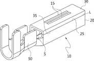
본 실시예의 리셉터클 터미널은 전체가 도전성 금속판으로 만들어진다. 리셉터클 터미널의 중간부분은 몸체부(도면부호 미부여)이고 길이방향 후단에는 바렐부(50)가 구비된다. 실제로 상기 몸체부는 상기 바렐부(50)나 아래에서 설명될 결합부(20)의 사이에 있는 것으로 굳이 상기 바렐부(50)나 결합부(20)와 구별하여 명명할 필요는 없다.The receptacle terminal of this embodiment is entirely made of a conductive metal plate. A middle portion of the receptacle terminal is provided with a body portion (not shown), and a
상기 바렐부(50)는 전선(도시되지 않음)이 전기적 그리고 물리적으로 연결되는 부분이다. 이를 위해 상기 바렐부(50)는 전선의 심선과 전기적으로 연결되는 전선바렐과 전선의 인슐레이션을 감싸 연결되는 인슐레이션바렐로 구성된다. 이들 전선바렐과 인슐레이션바렐은 대략 서로 마주보는 사각형의 판이 각각 전선의 심선과 전선의 인슐레이션을 감싸 압착시키게 된다.The
상기 몸체부의 선단에는 결합부(20)가 구비된다. 상기 결합부(20)는 상대 터미널인 탭터미널의 결합부(20)가 내부로 삽입되어 전기적 연결이 이루어지는 부분이다. 상기 결합부(20)의 내부에는 횡단면이 사각형인 사각통형상으로 내부에 상대 터미널이 삽입되는 결합공간(S)이 형성된다. 상기 결합공간(S)은 상기 결합부(20)의 전후방향으로 개방된다.A
상기 결합부(20)에는 탭접촉부(15)가 구비된다. 상기 탭접촉부(15)는 상대 탭터미널과의 접촉을 위한 것으로 결합공간(S) 내측으로 돌출되어 구비된다. 본 실시례에서 상기 탭접촉부(15)는 단순히 결합공간(S) 내측으로 요입된 형상이나, 상기 탭접촉부(15)는 몸체부의 일부가 절결된 후 절곡되어 결합공간(S)내측으로 돌출되게 가공되는 스프링부(미도시)일 수도 있다.The
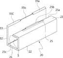
상기 결합부(20)의 구성을 보다 구체적으로 살펴본다. 상기 결합부(20)는 도 2를 기준으로 할 때, 베이스판(21)의 양단에서 제1측판(22)과 제2측판(32)이 각각 직각이 되게 연장되고, 상기 제1측판(22) 및 제2측판(32)으로부터 다시 직각으로 연장되어 제1상판(23) 및 제2상판(33)이 형성된다. 이들 베이스판(21), 제1측판(22), 제2측판(32), 제1상판(23) 및 제2상판(33)은 하나의 금속모재를 절곡하여 형성하는 것으로, 프로그레시브 금형을 이용하여 모재를 순차적으로 절곡시켜 형성될 수 있다.The configuration of the
이때, 상기 제1상판(23) 및 제2상판(33)은 서로 마주보는 방향으로 연장되어 그 일단이 서로 밀착된다. 그리고 밀착된 제1상판(23) 및 제2상판(33)으로 인하여 상기 결합공간(S)은 전후 양방향, 즉 상기 결합부(20)의 길이방향으로만 개방되고, 나머지 부분은 차폐된 구조를 가질 수 있다.At this time, the first
도 2에서 보듯이, 상기 제1상판(23) 및 제2상판(33)의 서로 밀착되는 부분(L)에는 각각 제1결합단(25) 및 제2결합단(35)이 형성된다. 상기 제1결합단(25)과 제2결합단(35)은 서로 밀착된 상태로 유지됨으로써, 상기 결합부(20)가 소정의 박스형상을 유지할 수 있다. 이를 위해 상기 제1결합단(25)과 제2결합단(35)이 서로 분리되지 않고 밀착된 형태를 유지하는 것이 중요한데, 리셉터클 터미널의 제조 후에 제1상판(23) 및 제2상판(33)이 스프링백 현상에 의해 서로 벌어지면서 이들 제1결합단(25) 및 제2결합단(35)이 서로 분리될 수 있다. 또한 결합부(20)의 성형과정이나 사용과정에서 가해지는 외력에 의해 상기 제1결합단(25)과 제2결합단(35)이 서로 어긋나, 상기 결합부(20)가 찌그러지거나 온전한 박스형태를 유지하지 못하는 경우가 있는데, 이하에서는 이러한 현상을 방지하기 위한 구조에 대해 설명하기로 한다.2, a
상기 결합부(20)에는 모재가 절곡되어 그 양단이 서로 밀착되는 제1결합단(25) 및 제2결합단(35)이 형성되는데, 상기 제1결합단(25) 및 제2결합단(35)은 상기 제1상판(23) 및 제2상판(33)이 서로 밀착되는 부분(L)으로, 상기 결합부(20)의 길이방향을 따라 길게 형성된다. 물론, 상기 제1결합단(25) 및 제2결합단(35)은 제1상판(23) 및 제2상판(33)이 아니라 결합부(20)의 측부나 하부에 형성될 수도 있으나, 본 실시례에서는 결합부(20)가 상부에서 결합되므로 제1상판(23) 및 제2상판(33)에 각각 형성된다.A
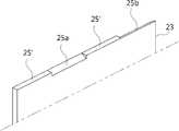
도 2에서 보듯이, 상기 제1결합단(25)에는 제1경사부(25a,25c) 및 제2경사부(25b)가 형성된다. 상기 제1경사부(25a,25c)와 제2경사부(25b)는 상기 제1결합단(25)이 제1상판(23)의 외면과 직교한 면을 이루지 않고, 어느 일방으로 경사지게 형성된 것으로, 일종의 모따기(chamfering) 구조로 볼 수 있다.As shown in FIG. 2, the first
상기 제1경사부(25a,25c)와 제2경사부(25b)는 서로 다른 방향으로 경사지게 형성된다. 보다 정확하게는, 도 4(a)에서 보듯이, 상기 제1경사부(25a)는 상기 제1결합단(25)이 가장 돌출된 일단으로 갈수록 폭이 좁아지도록 형성된다면, 도 4(b)에서 보듯이, 상기 제2경사부(25b)는 상기 제1결합단(25)이 가장 돌출된 일단으로 갈수록 폭이 넓어지게 형성되는 것이다.The first
그리고, 상기 제2결합단(35)에는 상기 제1경사부(25a,25c) 및 제2경사부(25b)에 대응하여 맞물리는 제1상대경사부(35a,35c) 및 제2상대경사부(35b)가 형성된다. 즉, 도 4에서 보듯이, 상기 제1상대경사부(35a,35c)는 제1경사부(25a,25c)와 반대방향으로 형성되고, 제2상대경사부(35b)는 제2경사부(25b)과 반대방향으로 형성되어, 서로 밀착되면 빈 공간 없이 맞물리도록 형성되는 것이다.The second relative inclined
이와 같이 서로 반대방향인 제1경사부(25a,25c) 및 제2경사부(25b)가 제1상대경사부(35a,35c) 및 제2상대경사부(35b)과 각각 밀착되면, 상기 결합부(20)의 제1결합단(25)과 제2결합단(35)이 서로 가까워지는 방향으로 외력이 가해지더라도, 제1경사부(25a,25c)-제1상대경사부(35a,35c)의 결합부위와, 제2경사부(25b)-제2상대경사부(35b)의 결합부위가 서로 보완하여 제1결합단(25) 및 제2결합단(35)이 서로 어느 일측으로 어긋나 분리되지 않고 지지될 수 있다. 이러한 기능을 보다 확실하게 구현하기 위하여, 바람직하게는 상기 제1경사부(25a,25c) 및 제2경사부(25b)는 서로 반대방향으로 경사지게 형성된다.When the first
이와 같이, 상기 제1결합단(25) 및 제2결합단(35)이 서로 어느 일측으로 어긋나 분리되지 않고 지지될 수 있기 때문에, 금형을 통해 모재를 접어 상기 결합부(20)를 가공하는 과정에서 보다 강한 힘으로 모재를 접을 수 있고, 따라서 결합부(20)의 스프링백 현상에 의해 상기 제1결합단(25) 및 제2결합단(35)이 서로 벌어지는 것을 방지할 수 있다.Since the
한편, 상기 제1경사부(25a,25c)와 상기 제2경사부(25b)는 상기 제1결합단(25)의 길이방항을 따라 서로 번갈아 형성된다. 도 2 및 도 3에서 보듯이, 상기 제1경사부(25a)와 이웃하여 제2경사부(25b)가 형성되고, 제2경사부(25b)와 이웃하여 다시 제1경사부(25c)가 형성되는 것이다. 물론, 상기 제2결합단(35)에는 이에 대응되는 개수 및 위치에 상기 제1상대경사부(35a,35c) 및 제2상대경사부(35b)가 형성된다. 참고로 두 제1경사부를 구분하기 위하여, 도면에는 각각 25a 및 25c의 부호를 각각 부여하였고, 두 제1상대경사부에는 각각 35a, 35c의 부호를 부여하였다.The first
그 결과, 도 4에서 보듯이, 첫번째 제1경사부(25a)-제1상대경사부(35a)의 결합부위(도 4(a))와, 제2경사부(25b)-제2상대경사부(35b)의 결합부위(도 4(b)) 및 두번째 제1경사부(25c)-제1상대경사부(35c)의 결합부위(도 4(c))의 경사각은 서로 번갈아 반대방향으로 형성될 수 있고, 따라서 제1결합단(25) 및 제2결합단(35)이 서로 어긋나는 것을 방지할 수 있다.As a result, as shown in Fig. 4, the first
이때, 도시되지는 않았으나, 상기 제1경사부(25a,25c) 및 제2경사부(25b)의 일측에는 각각 수평부가 형성되고, 제1상대경사부(35a,35c) 및 제2상대경사부(35b)의 일측에는 이에 대응되는 수평부가 형성될 수 있다. 상기 수평부는 제1경사부(25a,25c) 및 제2경사부(25b)와, 이에 대응하는 제1상대경사부(35a,35c) 및 제2상대경사부(35b)의 횡단면의 형상이 전체적으로 경사면으로 형성되지 않고 적어도 일부는 수평한 방향으로 연장된 부분을 형성하도록 한 것이다. 이는 상기 제1결합단(25) 및 제2결합단(35)에 서로 가까워지는 방향으로 외력이 가해질 때, 경사면 형상만으로 형성되는 것에 비하여, 서로 밀착된 수평면이 이러한 외력에 저항하는 힘을 더욱 커지게 한다. 물론, 경사면의 일단에 형성되는 날카로운 모서리를 생략함으로써, 작업자의 부상을 방지할 수도 있다.Although not shown, a horizontal portion is formed at one side of each of the first
도 5에는 본 발명에 의한 제1결합단(25)의 다른 실시례에 도시되어 있다. 앞선 실시례와 구별되는 부분에 대해서만 설명하면, 제1결합단(25)에는 제1경사부(25a,25c) 및 제2경사부(25b)가 서로 반대방향으로 각각 형성되고, 이와 별도로 상기 제1결합단(25)의 적어도 일부 구간에는 비경사면(25')이 형성된다. 상기 비경사면(25')이란 상기 제1경사부(25a,25c) 및 제2경사부(25b)와 달리 상기 제1상판(23)의 외면과 직교한 방향으로 형성되는 것으로, 모재를 가공하지 않은 부분에 해당한다. 도시되지는 않았으나, 상기 제2결합단(35)에도 상기 제1결합단(25)의 비경사면(25')에 대응되는 위치에, 대응되는 개수의 비경사면이 형성된다.Fig. 5 shows another embodiment of the
상기 비경사면(25')은 상기 제1결합단(25) 및 제2결합단(35) 보다 다양한 방향으로 밀착될 수 있도록 한다. 즉, 상기 제1경사부(25a,25c)에 의한 결합면의 방향, 제2경사부(25b)에 의한 결합면의 방향 및 상기 비경사면(25')에 의한 결합면의 방향이 각각 다르게 형성되고, 따라서 상기 제1결합단(25) 및 제2결합단(35) 사이가 보다 견고한 결합이 가능해진다.The non-oblique surface 25 'can be brought into close contact with the
이와 더불어, 상기 제1경사부(25a,25c)와 제2경사부(25b) 사이에 상기 비경사면(25')이 형성되면, 상기 제1경사부(25a,25c)와 제2경사부(25b)가 보다 정확한 형상으로 성형될 수 있다. 본 실시례와 같이 모재의 두께가 얇은 경우에는, 상기 제1경사부(25a,25c) 및 제2경사부(25b)가 연속적으로 형성될 경우 상기 제1경사부(25a,25c)와 제2경사부(25b)의 연결부분에서 정확한 형상의 가공이 다소 어려울 수 있다. 그러나 이와 같이 제1경사부(25a,25c) 및 제2경사부(25b) 사이에 가공할 필요가 없는 비경사면(25')이 형성됨으로써 제1경사부(25a,25c) 및 제2경사부(25b)의 형상이 보다 정확하게 구현될 수 있는 것이다.In addition, when the non-oblique surface 25 'is formed between the first
한편, 도 6에는 본 발명에 의한 리셉터클 터미널의 다른 실시례의 구성이 도시되어 있다. 이에 보듯이, 리셉터클 터미널의 결합부(20)는 그 측부에 결합단이 형성된다. 상기 결합부(20)는 모재를 절곡하여 형성되는데, 절곡된 모재의 양단이 결합부(20)의 측부에서 서로 밀착되는 것이다. 그리고, 모재가 밀착된 부분(L)에는 제1결합단(25) 및 제2결합단(35)이 형성되며, 상기 제1결합단(25)에는 제1경사부(25a,25c) 및 제2경사부(25b)가 형성되고, 제2결합단(35)에는 제1상대경사부(35a,35c) 및 제2상대경사부(35b)가 형성되는데, 그 구체적인 형상은 앞서 설명한 실시례와 동일하므로 설명을 생략하기로 한다.6 shows a configuration of another embodiment of the receptacle terminal according to the present invention. As shown in the figure, the
이하 상기한 바와 같은 구성을 가지는 본 발명에 의한 리셉터클 터미널이 만들어지는 것을 상세하게 설명한다.Hereinafter, the construction of the receptacle terminal according to the present invention having the above-described structure will be described in detail.
본 발명의 리셉터클 터미널을 제조하는 것은 띠 모양의 금속판재를 프레스장치에 연속적으로 공급하여 순차적으로 필요한 공정이 진행되도록 함에 의해 이루어진다. 즉, 몸체부, 바렐부(50) 그리고 결합부(20)가 동시에 또는 순차적으로 만들어지게 된다. 본 발명은 리셉터클 터미널의 결합부(20)가 가장 주요 구성이므로 도 2 및 도 3을 참고하여 결합부(20)와 관련된 설명을 주로 한다.The receptacle terminal of the present invention is manufactured by continuously supplying a strip-shaped metal plate to a press apparatus so that necessary processes are sequentially performed. That is, the body portion, the
상기 결합부(20)를 만들기 위해 상기 프레스장치로 상기 결합부(20)를 절곡하기에 앞서, 상기 결합부(20)가 절곡되어 서로 만나는 부분(L)인 제1결합단(25)과 제2결합단(35)이 가공되어야 한다. 즉, 상기 제1결합단(25) 및 제2결합단(35)에는 각각 제1경사부(25a,25c)/제2경사부(25b) 및 제1상대경사부(35a,35c)/제2상대경사부(35b)가 형성되는데, 이는 금형을 이용하여 모재를 펀칭함으로써 가공될 수 있다.Before the engaging
그리고, 상기 모재를 접으면 상기 결합부(20)의 제1상판(23) 및 제2상판(33)이 서로 가까워지는 방향으로 이동되고, 결국 상기 제1결합단(25) 및 제2결합단(35)이 서로 밀착하게 된다. 이때, 상기 제1경사부(25a,25c)는 제1상대경사부(35a,35c)와, 제2경사부(25b)는 제2상대경사부(35b)와 각각 밀착되어 결합면이 서로 반대방향의 경사면을 이루게 된다. 따라서, 제조과정에서 제1결합단(25) 및 제2결합단(35)이 가까워지는 방향으로 외력이 가해지더라도 상기 제1결합단(25) 및 제2결합단(35)이 서로 어긋나지 않는다.When the base material is folded, the first
이러한 리셉터클 터미널의 구조적 특징을 이용하여 스프링백 현상도 방지할 수도 있다. 즉, 상기 제1결합단(25) 및 제2결합단(35)이 큰 외력에도 어긋나지 않는 구조를 활용하여, 상기 제1결합단(25) 및 제2결합단(35)이 가까워지는 방향으로 큰 외력을 미리 가해줌으로써 결합부(20)에 잔존하는 탄성력을 제거하여 스프링백 현상을 방지할 수 있는 것이다.The springback phenomenon can also be prevented by utilizing the structural characteristics of such a receptacle terminal. That is, the
이와 같이 결합부(20)가 완성된 리셉터클 터미널은 상기 바렐부(50)에 전선이 연결된 상태로 커넥터하우징내에 삽입된다. 마지막으로 상대 커넥터의 상대 탭터미널이 상기 리셉터클 터미널의 결합공간(S)으로 삽입되어 두 커넥터 사이가 전기적으로 연결된다.The receptacle terminal completed with the
이상에서, 본 발명에 따른 실시례를 구성하는 모든 구성 요소들이 하나로 결합하거나 결합하여 동작하는 것으로 설명되었다고 해서, 본 발명이 반드시 이러한 실시례에 한정되는 것은 아니다. 즉, 본 발명의 목적 범위 안에서라면, 그 모든 구성 요소들이 하나 이상으로 선택적으로 결합하여 동작할 수도 있다. 또한, 이상에서 기재된 "포함하다", "구성하다" 또는 "가지다" 등의 용어는, 특별히 반대되는 기재가 없는 한, 해당 구성 요소가 내재할 수 있음을 의미하는 것이므로, 다른 구성 요소를 제외하는 것이 아니라 다른 구성 요소를 더 포함할 수 있는 것으로 해석되어야 한다. 기술적이거나 과학적인 용어를 포함한 모든 용어들은, 다르게 정의되지 않는 한, 본 발명이 속하는 기술 분야에서 통상의 지식을 가진 자에 의해 일반적으로 이해되는 것과 동일한 의미가 있다. 사전에 정의된 용어와 같이 일반적으로 사용되는 용어들은 관련 기술의 문맥상의 의미와 일치하는 것으로 해석되어야 하며, 본 발명에서 명백하게 정의하지 않는 한, 이상적이거나 과도하게 형식적인 의미로 해석되지 않는다.While the present invention has been described in connection with what is presently considered to be the most practical and preferred embodiments, it is to be understood that the invention is not limited to the disclosed embodiments. That is, within the scope of the present invention, all of the components may be selectively coupled to one or more of them. Furthermore, the terms "comprises", "comprising", or "having" described above mean that a component can be implanted unless otherwise specifically stated, But should be construed as including other elements. All terms, including technical and scientific terms, have the same meaning as commonly understood by one of ordinary skill in the art to which this invention belongs, unless otherwise defined. Commonly used terms, such as predefined terms, should be interpreted to be consistent with the contextual meanings of the related art, and are not to be construed as ideal or overly formal, unless expressly defined to the contrary.
이상의 설명은 본 발명의 기술 사상을 예시적으로 설명한 것에 불과한 것으로서, 본 발명이 속하는 기술 분야에서 통상의 지식을 가진 자라면 본 발명의 본질적인 특성에서 벗어나지 않는 범위에서 다양한 수정 및 변형이 가능할 것이다. 따라서, 본 발명에 개시된 실시례들은 본 발명의 기술 사상을 한정하기 위한 것이 아니라 설명하기 위한 것이고, 이러한 실시례에 의하여 본 발명의 기술 사상의 범위가 한정되는 것은 아니다. 본 발명의 보호 범위는 아래의 청구범위에 의하여 해석되어야 하며, 그와 동등한 범위 내에 있는 모든 기술 사상은 본 발명의 권리범위에 포함되는 것으로 해석되어야 할 것이다.The foregoing description is merely illustrative of the technical idea of the present invention, and various changes and modifications may be made by those skilled in the art without departing from the essential characteristics of the present invention. Therefore, the embodiments disclosed in the present invention are not intended to limit the scope of the present invention but to limit the scope of the technical idea of the present invention. The scope of protection of the present invention should be construed according to the following claims, and all technical ideas within the scope of equivalents should be construed as falling within the scope of the present invention.
20: 결합부21: 베이스판
22: 제1측판제1상판
25: 제1결합단25a, 25c: 제1경사부
25b: 제2경사부25': 비경사면
32: 제2측판33: 제2상판
35: 제2결합단35a, 35c: 제1상대경사부
35b: 제2상대경사부35': 비경사면20: engaging portion 21: base plate
22: first side plate first upper plate
25: first coupling
25b: second inclined portion 25 ': non-
32: second side plate 33: second top plate
35:
35b: a second relative inclined portion 35 ': a non-
Claims (6)
Translated fromKorean상기 몸체부의 일단에 구비되되 길이방향에 대해 직교한 방향으로 모재가 절곡되어 형성되고 상대 탭터미널이 삽입되어 결합되는 결합공간이 내부에 형성되는 결합부와,
상기 몸체부의 후단에 구비되어 전선과 연결되는 바렐부를 포함하고,
상기 결합부에는 모재가 절곡되어 그 양단이 서로 밀착되는 제1결합단 및 제2결합단이 형성되고,
상기 제1결합단에는 서로 다른 방향으로 경사지게 형성된 제1경사부 및 제2경사부가 상기 결합부의 길이방향을 따라 번갈아 형성되고, 상기 제2결합단에는 이에 대응하여 맞물리는 제1상대경사부 및 제2상대경사부가 형성되며,
서로 직교한 방향으로 형성된 상기 제1경사부 및 제2경사부가 상기 제1상대경사부 및 제2상대경사부와 각각 밀착하여 상기 결합부가 박스형상을 유지하고,
상기 제1경사부와 상기 제2경사부는 상기 제1결합단의 길이방항을 따라 서로 번갈아 형성되고, 상기 제2결합단에는 이에 대응되는 개수 및 위치에 상기 제1상대경사부 및 제2상대경사부가 형성되며,
상기 제1경사부, 제2경사부, 제1상대경사부 및 제2상대경사부는 각각 모재를 펀칭하여 모따기 구조로 만들어지되, 상기 제1결합단 및 제2결합단은 서로를 향해 돌출되지 않고 각각 결합부의 길이방향을 따라 연장되는 리셉터클 터미널.
A body portion,
A coupling part formed at one end of the body part and formed by bending a base material in a direction orthogonal to the longitudinal direction and having a coupling space in which a relative tap terminal is inserted and coupled,
And a barrel portion provided at a rear end of the body portion and connected to a wire,
Wherein the coupling portion is formed with a first coupling end and a second coupling end where the base material is bent and both ends thereof are in close contact with each other,
Wherein the first inclined portion and the second inclined portion, which are inclined in different directions, are alternately formed along the longitudinal direction of the coupling portion, and the first relative inclined portion and the second inclined portion are engaged with the second coupling end, 2 relative inclined portions are formed,
The first inclined portion and the second inclined portion formed in mutually orthogonal directions are in close contact with the first relative inclined portion and the second relative inclined portion so that the engaging portion maintains the box shape,
Wherein the first inclined portion and the second inclined portion are alternately formed along the length direction of the first coupling end, and the second coupling end is provided with the first relative inclined portion and the second relative inclination Further,
Wherein the first inclined portion, the second inclined portion, the first relative inclined portion, and the second relative inclined portion are made of a chamfered structure by punching the base material, wherein the first and second coupling ends are not protruded toward each other And each extending along the longitudinal direction of the engaging portion.
The receptacle terminal according to claim 1, wherein the first inclined portion and the second inclined portion are inclined in directions opposite to each other.
The receptacle terminal according to claim 3, wherein a horizontal portion is formed at one side of each of the first inclined portion and the second inclined portion, and a corresponding horizontal portion is formed at one side of the first relative inclined portion and the second relative inclined portion.
The receptacle terminal according to claim 3, wherein a non-oblique surface is formed in at least a portion of the first and second coupling ends.
The receptacle terminal according to claim 5, wherein the non-oblique surface is formed between the first inclined portion and the second inclined portion, and between the first relative inclined portion and the second relative inclined portion, respectively.
Priority Applications (1)
| Application Number | Priority Date | Filing Date | Title |
|---|---|---|---|
| KR1020150154227AKR101819968B1 (en) | 2015-11-04 | 2015-11-04 | Receptacle terminal |
Applications Claiming Priority (1)
| Application Number | Priority Date | Filing Date | Title |
|---|---|---|---|
| KR1020150154227AKR101819968B1 (en) | 2015-11-04 | 2015-11-04 | Receptacle terminal |
Publications (2)
| Publication Number | Publication Date |
|---|---|
| KR20170052141A KR20170052141A (en) | 2017-05-12 |
| KR101819968B1true KR101819968B1 (en) | 2018-01-19 |
Family
ID=58740522
Family Applications (1)
| Application Number | Title | Priority Date | Filing Date |
|---|---|---|---|
| KR1020150154227AExpired - Fee RelatedKR101819968B1 (en) | 2015-11-04 | 2015-11-04 | Receptacle terminal |
Country Status (1)
| Country | Link |
|---|---|
| KR (1) | KR101819968B1 (en) |
Citations (2)
| Publication number | Priority date | Publication date | Assignee | Title |
|---|---|---|---|---|
| JP2006302824A (en)* | 2005-04-25 | 2006-11-02 | Auto Network Gijutsu Kenkyusho:Kk | Shield connector |
| KR101337546B1 (en)* | 2012-09-04 | 2013-12-06 | 주식회사 연호전자 | Connector terminal |
- 2015
- 2015-11-04KRKR1020150154227Apatent/KR101819968B1/ennot_activeExpired - Fee Related
Patent Citations (2)
| Publication number | Priority date | Publication date | Assignee | Title |
|---|---|---|---|---|
| JP2006302824A (en)* | 2005-04-25 | 2006-11-02 | Auto Network Gijutsu Kenkyusho:Kk | Shield connector |
| KR101337546B1 (en)* | 2012-09-04 | 2013-12-06 | 주식회사 연호전자 | Connector terminal |
Also Published As
| Publication number | Publication date |
|---|---|
| KR20170052141A (en) | 2017-05-12 |
Similar Documents
| Publication | Publication Date | Title |
|---|---|---|
| US8795007B2 (en) | Terminal fitting | |
| JP6028699B2 (en) | Connector terminal, electrical connector, and electrical connector manufacturing method | |
| US8308492B2 (en) | Board-to-board connector | |
| US8342875B2 (en) | Board-to-board connector having a sidewall portion with a sloped guide surface with cut out | |
| US7419411B2 (en) | Exposed-spring female terminal | |
| CN104838543B (en) | Female end | |
| JP5859938B2 (en) | Receptacle connector and manufacturing method thereof | |
| EP3358647A1 (en) | Inter-battery connection device and inter-battery connection device assembly | |
| CN105226424B (en) | Bonder terminal and the connector including the bonder terminal | |
| JP2016091767A (en) | connector | |
| CN112335139A (en) | Joint connector | |
| US10622743B2 (en) | Terminal module with a conductive obliquely wound coil spring held against an electrical contact member and connector having such a terminal module | |
| JP2016189273A (en) | Connector and electrical connection device | |
| US20220399670A1 (en) | Terminal connection structure | |
| US20200373697A1 (en) | Terminal module | |
| JP2016081561A (en) | Female terminal | |
| CN205069919U (en) | Electric connector | |
| CN105940565B (en) | Female end | |
| KR101819968B1 (en) | Receptacle terminal | |
| CN106463869B (en) | female terminal | |
| CN105281080B (en) | Bonder terminal and the connector including the bonder terminal | |
| CN101783448B (en) | Board-to-board electrical connector | |
| CN103208690B (en) | Press-contact connector | |
| JP2021034307A5 (en) | ||
| JP2016207253A (en) | Connector and terminal fitting connection structure |
Legal Events
| Date | Code | Title | Description |
|---|---|---|---|
| A201 | Request for examination | ||
| PA0109 | Patent application | St.27 status event code:A-0-1-A10-A12-nap-PA0109 | |
| PA0201 | Request for examination | St.27 status event code:A-1-2-D10-D11-exm-PA0201 | |
| D13-X000 | Search requested | St.27 status event code:A-1-2-D10-D13-srh-X000 | |
| D14-X000 | Search report completed | St.27 status event code:A-1-2-D10-D14-srh-X000 | |
| E902 | Notification of reason for refusal | ||
| PE0902 | Notice of grounds for rejection | St.27 status event code:A-1-2-D10-D21-exm-PE0902 | |
| P11-X000 | Amendment of application requested | St.27 status event code:A-2-2-P10-P11-nap-X000 | |
| P13-X000 | Application amended | St.27 status event code:A-2-2-P10-P13-nap-X000 | |
| PG1501 | Laying open of application | St.27 status event code:A-1-1-Q10-Q12-nap-PG1501 | |
| E90F | Notification of reason for final refusal | ||
| PE0902 | Notice of grounds for rejection | St.27 status event code:A-1-2-D10-D21-exm-PE0902 | |
| E13-X000 | Pre-grant limitation requested | St.27 status event code:A-2-3-E10-E13-lim-X000 | |
| P11-X000 | Amendment of application requested | St.27 status event code:A-2-2-P10-P11-nap-X000 | |
| P13-X000 | Application amended | St.27 status event code:A-2-2-P10-P13-nap-X000 | |
| E701 | Decision to grant or registration of patent right | ||
| PE0701 | Decision of registration | St.27 status event code:A-1-2-D10-D22-exm-PE0701 | |
| PR0701 | Registration of establishment | St.27 status event code:A-2-4-F10-F11-exm-PR0701 | |
| PR1002 | Payment of registration fee | St.27 status event code:A-2-2-U10-U11-oth-PR1002 Fee payment year number:1 | |
| PG1601 | Publication of registration | St.27 status event code:A-4-4-Q10-Q13-nap-PG1601 | |
| P22-X000 | Classification modified | St.27 status event code:A-4-4-P10-P22-nap-X000 | |
| PR1001 | Payment of annual fee | St.27 status event code:A-4-4-U10-U11-oth-PR1001 Fee payment year number:4 | |
| PR1001 | Payment of annual fee | St.27 status event code:A-4-4-U10-U11-oth-PR1001 Fee payment year number:5 | |
| PC1903 | Unpaid annual fee | St.27 status event code:A-4-4-U10-U13-oth-PC1903 Not in force date:20230113 Payment event data comment text:Termination Category : DEFAULT_OF_REGISTRATION_FEE | |
| PC1903 | Unpaid annual fee | St.27 status event code:N-4-6-H10-H13-oth-PC1903 Ip right cessation event data comment text:Termination Category : DEFAULT_OF_REGISTRATION_FEE Not in force date:20230113 |