KR101819253B1 - Energy Storage device and method of operating the same - Google Patents
Energy Storage device and method of operating the sameDownload PDFInfo
- Publication number
- KR101819253B1 KR101819253B1KR1020130103507AKR20130103507AKR101819253B1KR 101819253 B1KR101819253 B1KR 101819253B1KR 1020130103507 AKR1020130103507 AKR 1020130103507AKR 20130103507 AKR20130103507 AKR 20130103507AKR 101819253 B1KR101819253 B1KR 101819253B1
- Authority
- KR
- South Korea
- Prior art keywords
- unit price
- power
- unit
- time zone
- energy storage
- Prior art date
- Legal status (The legal status is an assumption and is not a legal conclusion. Google has not performed a legal analysis and makes no representation as to the accuracy of the status listed.)
- Active
Links
Images


Classifications
- H—ELECTRICITY
- H02—GENERATION; CONVERSION OR DISTRIBUTION OF ELECTRIC POWER
- H02J—CIRCUIT ARRANGEMENTS OR SYSTEMS FOR SUPPLYING OR DISTRIBUTING ELECTRIC POWER; SYSTEMS FOR STORING ELECTRIC ENERGY
- H02J3/00—Circuit arrangements for AC mains or AC distribution networks
- H02J3/28—Arrangements for balancing of the load in a network by storage of energy
- G—PHYSICS
- G06—COMPUTING OR CALCULATING; COUNTING
- G06Q—INFORMATION AND COMMUNICATION TECHNOLOGY [ICT] SPECIALLY ADAPTED FOR ADMINISTRATIVE, COMMERCIAL, FINANCIAL, MANAGERIAL OR SUPERVISORY PURPOSES; SYSTEMS OR METHODS SPECIALLY ADAPTED FOR ADMINISTRATIVE, COMMERCIAL, FINANCIAL, MANAGERIAL OR SUPERVISORY PURPOSES, NOT OTHERWISE PROVIDED FOR
- G06Q50/00—Information and communication technology [ICT] specially adapted for implementation of business processes of specific business sectors, e.g. utilities or tourism
- G06Q50/06—Energy or water supply
- Y—GENERAL TAGGING OF NEW TECHNOLOGICAL DEVELOPMENTS; GENERAL TAGGING OF CROSS-SECTIONAL TECHNOLOGIES SPANNING OVER SEVERAL SECTIONS OF THE IPC; TECHNICAL SUBJECTS COVERED BY FORMER USPC CROSS-REFERENCE ART COLLECTIONS [XRACs] AND DIGESTS
- Y02—TECHNOLOGIES OR APPLICATIONS FOR MITIGATION OR ADAPTATION AGAINST CLIMATE CHANGE
- Y02E—REDUCTION OF GREENHOUSE GAS [GHG] EMISSIONS, RELATED TO ENERGY GENERATION, TRANSMISSION OR DISTRIBUTION
- Y02E60/00—Enabling technologies; Technologies with a potential or indirect contribution to GHG emissions mitigation
- Y02E60/10—Energy storage using batteries
- Y—GENERAL TAGGING OF NEW TECHNOLOGICAL DEVELOPMENTS; GENERAL TAGGING OF CROSS-SECTIONAL TECHNOLOGIES SPANNING OVER SEVERAL SECTIONS OF THE IPC; TECHNICAL SUBJECTS COVERED BY FORMER USPC CROSS-REFERENCE ART COLLECTIONS [XRACs] AND DIGESTS
- Y04—INFORMATION OR COMMUNICATION TECHNOLOGIES HAVING AN IMPACT ON OTHER TECHNOLOGY AREAS
- Y04S—SYSTEMS INTEGRATING TECHNOLOGIES RELATED TO POWER NETWORK OPERATION, COMMUNICATION OR INFORMATION TECHNOLOGIES FOR IMPROVING THE ELECTRICAL POWER GENERATION, TRANSMISSION, DISTRIBUTION, MANAGEMENT OR USAGE, i.e. SMART GRIDS
- Y04S10/00—Systems supporting electrical power generation, transmission or distribution
- Y04S10/14—Energy storage units
Landscapes
- Engineering & Computer Science (AREA)
- Business, Economics & Management (AREA)
- Economics (AREA)
- Health & Medical Sciences (AREA)
- Human Resources & Organizations (AREA)
- Strategic Management (AREA)
- Water Supply & Treatment (AREA)
- General Health & Medical Sciences (AREA)
- Power Engineering (AREA)
- Marketing (AREA)
- Primary Health Care (AREA)
- Public Health (AREA)
- Tourism & Hospitality (AREA)
- Physics & Mathematics (AREA)
- General Business, Economics & Management (AREA)
- General Physics & Mathematics (AREA)
- Theoretical Computer Science (AREA)
- Charge And Discharge Circuits For Batteries Or The Like (AREA)
- Supply And Distribution Of Alternating Current (AREA)
Abstract
Translated fromKoreanDescription
Translated fromKorean본 발명은 에너지 저장장치 및 그 동작 방법에 관한 것이다.The present invention relates to an energy storage device and a method of operation thereof.
배터리 에너지 저장장치(BESS:Battery Energy Storage System)은 발전소나 신재생 에너지 발전 시설에서 생산된 전력을 전력 계통(그리드:Grid)에 저장하였다가 전력 피크와 같이 가장 필요한 때에 공급하여 에너지를 효율적인 이용이 가능하도록 도와 준다. 이러한 에너지 저장 장치는 1차적으로 전력 공급의 안정화와 더불어 신재생 에너지의 확산에 기여할 수 있다.The battery energy storage system (BESS) stores power generated by a power plant or a new and renewable energy generation facility in a grid (grid), and supplies energy when necessary, such as a power peak, It helps to be possible. These energy storage devices can primarily contribute to the stabilization of power supply and the spread of renewable energy.
또한 배터리 에너지 저장장치의 사용목적은 저가격 전력 시간대에 전력을 저장하였다가 고가격 전력 시간대에 기 저장해두었던 전력을 사용하도록 하는 구조를 가진다. 따라서 고가격의 전력을 저가격의 전력으로 사용할 수 있도록 함으로써 경제적 이득을 취할 수 있으며, 전력 시장 전체적인 전력 피크 시의 부하관리를 용이하게 할 수 있다.In addition, the purpose of the battery energy storage device is to store power in a low-power power time zone and to use power stored in a high power power time zone. Therefore, it is possible to use the high-priced power as low-cost power, so that the economic gain can be obtained and the load management in the power market as a whole can be facilitated.
종래의 배터리 에너지 저장장치는 배터리가 가지고 있는 전력량, 배터리로 충전 또는 방전되는 순시 전력 등이 표시되고 있다.The conventional battery energy storage device displays the amount of power the battery has, the instantaneous power charged or discharged by the battery, and the like.
배터리 에너지 저장장치의 방전 시 일반 가정에서는 사용자가 상기한 정보들을 기초하여 가정에서 사용하는 부하(형광등, 냉장고 등)을 직접 관리하게 되는데 일반 사용자가 배터리의 축전량과 방전시의 순시 전력만을 가지고 판단하여 댁내 부하를 관리하는 것은 한계가 있다.In the case of discharging the battery energy storage device, the user directly manages the load (fluorescent lamp, refrigerator, etc.) used in the home based on the above information by the user. The general user judges only the instantaneous electric power There is a limitation in managing the in-house load.
도 1은 종래의 시간대별 전력 단가 및 사용량을 나타낸 그래프이고, 도 2는 종래의 배터리 에너지 저장장치의 충방전 일정을 설정하기 위한 예시도이다.FIG. 1 is a graph showing a conventional power unit price and usage amount by time slot, and FIG. 2 is an exemplary diagram for setting a charging / discharging schedule of a conventional battery energy storage device.
도 1 내지 도 2를 참조하면, 일반적인 배터리 에너지 저장장치의 충전 및 방전 일정은 도 2에 도시된 바와 같이 충전 시간대 설정(210)을 위한 충전 시작시간과 충전 종료시간을 설정하고, 방전 시간대 설정(220)을 위한 방전 시작시간과 방전 종료시간을 사용자가 입력하게 되어 있다. 그러나 보통의 경우 도 1의 (a)와 같이 시간대별 전력 단가를 적용 받게 되면, 실제 사용하는 전력량은 도 1(b)와 같이 실제 사용하는 전력량은 일일 평균 사용량을 사용하게 된다. 따라서 도 2에서와 같이 시간대별 충전 및 방전의 스케줄링이 정확해야 하는데 정격 충전량에 기반한 배터리 에너지 저장장치는 정확하게 정격량을 100% 충전 및 방전을 수행하기 어렵다.Referring to FIGS. 1 and 2, a charging and discharging schedule of a general battery energy storage device is set by setting a charging start time and a charging end time for the charging
또한, 배터리 에너지 저장장치의 방전 시 방전 일정 시간대를 잘못 설정하면 예정된 방전시간 보다 빨리 방전되거나 예정된 방전 시간 후에도 많은 축전량이 남아 있을 수 있다.In addition, if the discharge time period of the battery energy storage device is erroneously set, it is possible to discharge more quickly than a predetermined discharge time or to retain a large amount of electric charge even after a predetermined discharge time.
본 발명은 배터리 에너지 저장장치의 충전 및 방전의 일정을 전력단가에 기반하여 설정할 수 있도록 하기 위한 배터리 에너지 저장장치 및 그 동작 방법을 제공한다.The present invention provides a battery energy storage device and a method of operating the battery energy storage device so that the charging and discharging of the battery energy storage device can be set based on the power unit price.
또한, 배터리 에너지 저장장치의 충전 및 방전을 100%까지 사용 가능할 수 있도록 하는 배터리 에너지 저장장치 및 그 동작 방법을 제공한다.The present invention also provides a battery energy storage device and a method of operating the battery energy storage device so that charge and discharge of the battery energy storage device can be used up to 100%.
본 발명의 실시 예에 따른 배터리 에너지 저장장치에 있어서, 전력시스템으로부터 전력 단가 정보를 수집하는 전력 단가 수집부; 축전기에 충전 전력량 정보를 수집하는 충전량 모니터링부; 상기 축전기에 충전된 전력을 방전하는 방전량을 수집하는 방전량 모니터링부; 상기 전력 단가 수집부에서 수집된 전력 단가를 기초하여 상기 축전기에 전력을 충전 또는 방전하기 위한 일정을 설정하는 충방전 판단부;를 포함한다.A battery energy storage device according to an embodiment of the present invention includes: a power unit price collector for collecting power unit price information from a power system; A charge amount monitoring unit for collecting charge amount information on a capacitor; A discharge amount monitoring unit for collecting a discharge amount for discharging electric power charged in the capacitor; And a charge / discharge determination unit for setting a schedule for charging or discharging electric power to / from the capacitor based on the power unit price collected by the power unit price collection unit.
본 발명에 따르면, 배터리 에너지 저장장치 및 그 동작 방법은 시간대별 전력 단가에 기초하여 배터리 에너지 저장장치의 충방전 일정을 설정함으로써, 경제적이고 효율적인 배터리 에너지 저장장치의 운용을 가능하게 할 수 있다.According to the present invention, the battery energy storage device and the operation method thereof can set the charging / discharging schedule of the battery energy storage device based on the unit cost of each time slot, thereby enabling the economical and efficient operation of the battery energy storage device.
도 1은 종래의 시간대별 전력 단가 및 사용량을 나타낸 그래프이다.
도 2는 종래의 배터리 에너지 저장장치의 충방전 일정을 설정하기 위한 예시도이다.
도 3은 본 발명의 실시 예가 적용되는 배터리 에너지 저장장치의 충방전을 위한 장치 블록 구성도이다.
도 4는 본 발명의 실시 예에 따른 배터리 에너지 저장장치의 충전 일정 설정 모드의 동작 흐름도이다.
도 5는 본 발명의 실시 예에 따른 배터리 에너지 저장장치의 방전 일정 설정 모드의 동작 흐름도이다.
도 6은 본 발명의 실시 예가 적용된 배터리 에너지 저장장치의 충방전량을 나타낸 그래프이다.
도 7은 본 발명의 실시 예가 적용된 배터리 에너지 저장장치의 전력 사용량 그래프이다.FIG. 1 is a graph showing a conventional power unit price and usage amount by time slot.
FIG. 2 is an exemplary diagram for setting a charge / discharge cycle of a conventional battery energy storage device.
3 is a block diagram of a device for charging / discharging a battery energy storage device to which an embodiment of the present invention is applied.
FIG. 4 is a flowchart illustrating an operation of a charge schedule setting mode of a battery energy storage device according to an embodiment of the present invention.
5 is a flowchart illustrating a discharge constant setting mode of the battery energy storage apparatus according to an embodiment of the present invention.
6 is a graph showing the charge-discharge amount of the battery energy storage device to which the embodiment of the present invention is applied.
7 is a graph of power consumption of a battery energy storage device to which an embodiment of the present invention is applied.
이하 도면을 참조하여 본 발명의 실시 예를 상세히 설명한다.Hereinafter, embodiments of the present invention will be described in detail with reference to the drawings.
도 3은 본 발명의 실시 예가 적용되는 배터리 에너지 저장장치의 충방전을 위한 장치 블록 구성도이다.3 is a block diagram of a device for charging / discharging a battery energy storage device to which an embodiment of the present invention is applied.
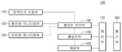
도 3을 참조하면, 본 발명의 실시 예가 적용되는 배터리 에너지 저장장치의 충방전을 위한 장치(100)는 전력 단가 수집부(110), 충전량 모니터링부(120), 방전량 모니터링부(130), 충방전 판단부(140), 충방전부(150), 계량부(160), 제어부(170) 및 통신부(180)를 포함한다.3, an
전력 단가 수집부(110)는 전력시스템으로부터 전력 사용 요금에 관련된 정보를 획득할 수 있다. 전력 단가는 시간대에 따라 차별화되어 과금될 수 있다. 전력 단가 수집부(110)는 전력 계통, 전력 거래소 및 각종 전력 관리 서버 등으로부터 시간에 따라 변하는 전력 사용 요금에 대한 정보를 수집할 수 있다. 상기 전력 단가는 월 또는 일 또는 실시간으로 수집될 수 있다.The power unit
충전량 모니터링부(120)는 배터리 에너지 저장장치에 충전된 전력 충전량에 관한 정보를 수집한다.The charged
방전량 모니터링부(130)는 배터리 에너지 저장장치에서 방전되는 전력 방전량에 관한 정보를 수집 할 수 있다. 즉, 댁내에서 배터리 에너지 저장장치에 연결되는 적어도 하나의 부하의 전력 사용에 따라 기 충전된 전력에 대한 방전 상태를 모니터링 할 수 있다.The discharge
충방전 판단부(140)는 전력 단가 정보 및 전력의 충방전량에 관한 정보에 기초하여 배터리 에너지 저장장치의 충전 및 방전에 대한 여부 및 일정을 판단할 수 있다.The charge /
충방전 판단부(140)는 배터리 에너지 저장장치의 충방전 속도에 대해서도 결정할 수 있다.The charge /
충방전부(150)는 충방전 판단부(140)에서 결정한 충방전 여부에 기초하여 배터리 에너지 저장장치에 전력을 충전하거나 방전할 수 있다. 충방전부(150)는 전력 시스템으로부터 수신하는 전력을 배터리 에너지 저장장치로 제공하여 댁내 부하에서 소비할 전력에 대한 충전을 할 수 있으며, 상기 충전된 전력에 대하여 부하 사용량에 기초하여 방전할 수 있다.The
계량부(160)는 배터리 에너지 저장장치와 충방전을 통하여 송수신하는 전력 사용량을 측정하여 과금될 전력 요금 및 부하 사용량에 따른 전력 사용량을 확인할 수 있다.The
계량부(160)는 전력 사용량에 비례하여 과금될 전력 사용량과 배터리 에너지 저장장치에 충방전된 전력 사용량에 따른 과금 전력 사용가격을 측정하여 표시할 수 있다. 또한 계량부(160)는 통신부(180)를 통하여 연결된 복수의 댁내 전력 사용량에 대한 정보를 측정 및 표시할 수 있다.The
계량부(160)는 배터리 에너지 저장장치가 충전되는 경우에는 충전되는 전력량에 기초하여 계측기를 순방향으로 수행하도록 하고, 방전되는 경우에는 방전되는 전력량에 기초하여 계측기가 역방향으로 계측이 수행되도록 할 수 있다.The
제어부(170)는 배터리 에너지 저장장치의 전체적인 작동을 제어할 수 있다. 제어부(170)는 전력단가 수집부(110)를 통하여 획득된 시간대별 전력 단가 정보를 기초하여 충방전 판단부(140)에서 전력을 충방전 할 수 있도록 제어할 수 있다.The
통신부(180)는 전력 충방전의 판단 및 전력 단가 산출 등에 요구되는 각종 정보를 획득하고, 댁내 부하 사용량에 따른 전력 사용량 정보를 송수신할 수 있다. 또한 통신부(180)는 연결된 댁내의 정보 및 부하정보를 획득하고 제어부(170)로 출력할 수 있다. 상기 통신부(180)는 충방전된 전력량에 대한 정보를 해당 댁내로 전송할 수 있다.
The
이하, 도 4 내지 도 5를 참조하여 본 발명의 실시 예에 따른 배터리 에너지 저장장치의 전력 충방전 일정을 설정하기 위한 동작을 상세히 설명한다.
Hereinafter, an operation for setting the electric charge / discharge schedule of the battery energy storage device according to the embodiment of the present invention will be described in detail with reference to FIG. 4 to FIG.
도 4는 본 발명의 실시 예에 따른 배터리 에너지 저장장치의 충전 일정 설정 모드의 동작 흐름도이다.FIG. 4 is a flowchart illustrating an operation of a charge schedule setting mode of a battery energy storage device according to an embodiment of the present invention.
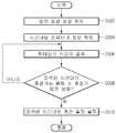
도 4를 참조하면 제어부(170)는 배터리 에너지 저장장치의 전력 충전 일정을 설정하기 위한 충전 일정 설정 모드(S402)를 실행하고, 전력단가 수집부(110)에서 일일 시간대별 전력 단가 정보를 획득할 수 있다.(S404) 전력단가 수집부(110)는 일일 시간대별 전력 단가에 대한 정보 외에도 소정 기간 동안 수집되는 전력 단가에 대하여 시간대별 단가에 대한 평균을 산출하여 시간대별 전력 단가를 획득할 수 있다.Referring to FIG. 4, the
제어부(170)는 상기 획득된 시간대별 전력 단가에 대한 정보를 기초하여 최소 단가를 가지는 적어도 하나의 시간대를 검색할 수 있다(S406) 상기 최소 단가에 대한 기준은 사용자 설정에 따른 기준 단가 또는 일일 전력 사용량에 따른 전력 사용량가의 평균값을 기초하여 그 이하를 최소 단가로 설정할 수 있다. 또한 전력 사용량이 적은 시간대에 전력 단가가 적게 책정되는 경우가 일반적이기 때문에 전력 사용량이 적은 시간대에 적용된 전력 단가를 최소 단가로 적용할 수 있다. 상기 최소단가를 분류하는 기준은 다양하게 적용될 수 있다.The
충방전 판단부(140)는 상기 검색된 최소단가를 가지는 시간대의 충전 가능 용량을 산출하고 상기 최소단가를 가지는 시간대의 충전 가능 용량이 축전기 용량 이상인지를 판단할 수 있다.(S408) 즉, 검색된 최소 단가를 가지는 한정된 시간대 또는 해당 시간대에 공급되는 전력량이 충전 대상 축전기의 충전 용량 이상이어야 한다. 따라서 충방전 판단부(140)는 상기 검색된 시간대에서 충전 가능한 전력이 충전 대상 축전기의 용량 미만인 경우 상기 검색된 시간대 이외의 최소 단가를 가지는 시간대를 재검색할 수 있다.The charge /
반면, 충방전 판단부(140)는 상기 검색된 시간대에서 충전 가능한 전력이 충전 대상 축전기의 용량 이상인 경우 상기 검색된 시간대로 충전 일정을 설정할 수 있다.(S410)
If the chargeable electric power is equal to or greater than the capacity of the charge object capacitor in the searched time zone, the charge /
상기와 같이 본 발명의 실시 예에 따라 일일 또는 소정 기간 동안에 획득된 시간대별 전력 단가를 기초하여 최소 단가를 가지는 시간대를 검색하여 해당 시간대를 충전 일정으로 설정할 수 있다.
As described above, according to the embodiment of the present invention, the time zone having the minimum unit price can be searched based on the unit price of power acquired per day or a predetermined period, and the corresponding time zone can be set as the charging schedule.
도 5는 본 발명의 실시 예에 따른 배터리 에너지 저장장치의 방전 일정 설정 모드의 동작 흐름도이다.5 is a flowchart illustrating a discharge constant setting mode of the battery energy storage apparatus according to an embodiment of the present invention.
도 5를 참조하면, 제어부(170)는 배터리 에너지 저장장치의 전력 방전 일정을 설정하기 위한 방전 일정 설정모드(S502)를 실행하고, 전력단가 수집부(110)에서 일일 시간대별 전력 단가 정보를 획득할 수 있다.(S504) 전력단가 수집부(110)는 일일 시간대별 전력 단가에 대한 정보 외에도 소정 기간 동안 수집되는 전력 단가에 대하여 시간대별 단가에 대한 평균을 산출하여 시간대별 전력 단가를 획득할 수 있다.5, the
제어부(170)는 상기 획득된 시간대별 전력 단가에 대한 정보를 기초하여 최대 단가를 가지는 적어도 하나의 시간대를 검색할 수 있다.(S506) 상기 최대 단가에 대한 기준 역시 최소 단가의 기준을 설정하기 위한 다양한 예와 유사하게 설정될 수 있다. 상기 최대 단가에 대한 기준은 사용자 설정에 따른 기준 단가 또는 일일 전력 사용량에 따른 전력 사용량가의 평균값을 기초하여 초과하는 값을 최고단가로 설정할 수 있다. 또한 전력 사용량이 많은 시간대에 전력 단가가 높게 책정되는 경우가 일반적이기 때문에 전력 사용량이 많은 시간대에 적용된 전력 단가를 최대 단가로 적용할 수 있다. 상기 최대 단가를 분류하는 기준은 다양하게 적용될 수 있다.The
충방전 판단부(140)는 상기 검색된 최대 단가를 가지는 시간대의 방전 가능 용량을 산출하고, 상기 최대 단가를 가지는 시간대의 방전 가능 용량이 축전기 방전 용량 이상인지를 판단할 수 있다.(S508) 즉, 검색된 최대 단가를 가지는 한정된 시간대 또는 해당 시간대에 소비되는 전력량이 방전 대상 축전기의 방전 용량 이상이어야 한다. 따라서 충방전 판단부(140)는 상기 검색된 시간대에서 방전 가능한 전력이 방전 대상 축전기의 용량 미만인 경우 상기 검색된 시간대 이외의 최대 단가를 가지는 시간대를 재검색 할 수 있다.The charge /
반면, 충방전 판단부(140)는 상기 검색된 시간대에서 방전 가능한 전력이 방전 대상 축전기의 용량 이상인 경우 상기 검색된 시간대로 방전 일정을 설정할 수 있다.(S510)
Meanwhile, the charge /
상기와 같이 본 발명의 실시 예에 따라 일일 또는 소정 기간 동안에 획득된 시간대별 전력 단가를 기초하여 최대 단가를 가지는 시간대를 검색하여 해당 시간대를 방전 일정으로 설정할 수 있다.As described above, according to the embodiment of the present invention, the time zone having the maximum unit price can be searched based on the unit price of the power acquired for one day or a predetermined period, and the corresponding time zone can be set as the discharge schedule.
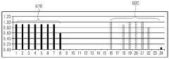
도 6은 본 발명의 실시 예가 적용된 배터리 에너지 저장장치의 충방전량을 나타낸 그래프이고, 도 7은 본 발명의 실시 예가 적용된 배터리 에너지 저장장치의 전력 사용량 그래프이다.FIG. 6 is a graph showing the charge-discharge amount of the battery energy storage device to which the embodiment of the present invention is applied, and FIG. 7 is a graph of power consumption of the battery energy storage device to which the embodiment of the present invention is applied.
도 6 내지 도 7을 참고하면, 상기 도 4 내지 도 5에서 설명한 충전 또는 방전 일정으로 설정된 시간대와 같이 전력 사용량이 적은 새벽 시간대(610)가 전력 단가가 최소단가로 설정됨에 따라 해당 시간대를 충전 시간대 일정으로 설정하고, 전력을 충전할 수 있다. 또한 오후 내지 저녁 시간대(620)가 전력 단가가 최대단가로 설정됨에 따라 해당 시간대를 방전 시간대로 설정하고 전력을 방전할 수 있다.6 to 7, in the early
상기와 같이 설정된 충방전 일정 설정에 따라 도 7에 도시된 바와 같이 종래의 전력 사용량에 대한 상태와 반대 상태의 현상이 나타날 수 있다. 즉, 종래의 전력 사용량이 높았던 시간대에는 본 발명의 실시 예에 따라 기 충전된 전력을 방전하는 시간대로 일정이 설정됨에 따라 과금되는 전력 사용량이 현저하게 줄어들 수 있다. 또한 종래의 전력 사용량이 낮았던 시간대인 새벽 시간대에서는 기 방전된 전력을 충전하기 위하여 과금되는 전력 사용량이 증가하는 현상이 나타날 수 있다.
As shown in FIG. 7, according to the charging / discharging schedule set as described above, the phenomenon of the opposite state to the state of the conventional power consumption can be shown. That is, according to the embodiment of the present invention, the amount of electric power to be charged can be remarkably reduced as a predetermined period is set for discharging the pre-charged electric power at a time when the conventional electric power consumption is high. Also, in the early morning hours, which is the time when the conventional power consumption is low, the amount of electric power charged for charging the discharged electricity may increase.
이상의 설명은 본 발명의 기술 사상을 예시적으로 설명한 것에 불과한 것으로서, 본 발명이 속하는 기술 분야에서 통상의 지식을 가진 자라면 본 발명의 본질적인 특성에서 벗어나지 않는 범위에서 다양한 수정 및 변형이 가능할 것이다.The foregoing description is merely illustrative of the technical idea of the present invention, and various changes and modifications may be made by those skilled in the art without departing from the essential characteristics of the present invention.
따라서, 본 발명에 개시된 실시 예들은 본 발명의 기술 사상을 한정하기 위한 것이 아니라 설명하기 위한 것이고, 이러한 실시 예에 의하여 본 발명의 기술 사상의 범위가 한정되는 것은 아니다.Therefore, the embodiments disclosed in the present invention are intended to illustrate rather than limit the scope of the present invention, and the scope of the technical idea of the present invention is not limited by these embodiments.
본 발명의 보호 범위는 아래의 청구범위에 의하여 해석되어야 하며, 그와 등한 범위 내에 있는 모든 기술 사상은 본 발명의 권리범위에 포함되는 것으로 해석되어야 할 것이다.The scope of protection of the present invention should be construed according to the following claims, and all technical ideas which are within the same range should be construed as being included in the scope of the present invention.
Claims (6)
Translated fromKorean전력시스템으로부터 전력 단가 정보를 수집하는 전력 단가 수집부;
축전기에 충전 전력량 정보를 수집하는 충전량 모니터링부;
상기 축전기에 충전된 전력을 방전하는 방전량을 수집하는 방전량 모니터링부;
상기 전력 단가 수집부에서 수집된 전력 단가를 기초하여 상기 축전기에 전력을 충전 또는 방전하기 위한 일정을 설정하는 충방전 판단부; 및
상기 전력 단가 정보에 기초하여 최소 단가를 가지는 제1 시간대와, 최대 단가를 가지는 제2 시간대를 검색하는 제어부를 포함하고,
상기 최소 단가는
상기 전력 단가가 사용자 설정에 따른 기준 단가 이하인 단가 또는 일일 전력 사용량에 따른 전력 사용량가의 평균값 이하인 단가로 설정되고,
상기 최대 단가는
상기 전력 단가가 사용자 설정에 따른 기준 단가를 초과하는 단가 또는 일일 전력 사용량에 따른 전력 사용량가의 평균값을 초과하는 단가로 설정되고,
상기 충방전 판단부는
상기 제1 시간대의 충전 가능 용량을 산출하고, 상기 산출된 제1 시간대의 충전 가능 용량이 상기 축전기 용량 이상이면 제1 시간대를 충전 일정으로 설정하고, 상기 제1 시간대의 충전 가능 용량이 상기 축전기 용량 미만이면 제1 시간대 이외의 최소 단가를 갖는 시간대를 재검색하여 충전 일정을 설정하고,
상기 제2 시간대의 방전 가능 용량을 산출하고, 상기 산출된 제2 시간대의 방전 가능 용량이 상기 축전기 방전 용량 이상이면 제2 시간대를 방전 일정으로 설정하고, 상기 제2 시간대의 방전 가능 용량이 상기 축전기의 방전 용량 미만이면 상기 제2 시간대 이외의 최대 단가를 갖는 시간대를 재검색하여 방전 일정을 설정하는
배터리 에너지 저장장치.A battery energy storage device comprising:
A power unit price collector for collecting power unit price information from the power system;
A charge amount monitoring unit for collecting charge amount information on a capacitor;
A discharge amount monitoring unit for collecting a discharge amount for discharging electric power charged in the capacitor;
A charge / discharge judgment unit for setting a schedule for charging or discharging electric power to / from the capacitor based on the unit price of the electric power collected by the electric power unit price collecting unit; And
A first time zone having a minimum unit price based on the power unit price information and a second time zone having a maximum unit price,
The minimum unit price
The power unit price is set to a unit price that is equal to or less than a reference unit price according to a user setting, or a unit price that is equal to or less than an average value of power usage amount according to a daily power usage amount,
The maximum unit price
Wherein the power unit price is set to a unit price exceeding a reference unit price according to a user setting or a unit price exceeding an average value of power usage amount according to a daily power usage amount,
The charge /
Calculating a chargeable capacity in the first time zone and setting a first time zone as a charge schedule if the calculated chargeable capacity in the first time zone is equal to or greater than the chargeable capacity in the first time zone, The charging time schedule is set by re-searching the time zone having the minimum unit price other than the first time zone,
The dischargeable capacity of the second time zone is set to a discharge constant of the second time zone when the calculated dischargeable capacity of the second time zone is equal to or more than the capacitor discharge capacity, , The time zone having the maximum unit price outside the second time zone is re-searched to set the discharge schedule
Battery energy storage.
상기 충전 또는 방전되는 전력량에 기초하여 전력 사용량을 계측하고 상기 계측된 전력 사용량을 기초하여 미리 설정된 기준에 따라 요금을 산출하는 계량부;를 더 포함하는
배터리 에너지 저장장치.The method according to claim 1,
And a metering unit for measuring a power usage amount based on the amount of electric power charged or discharged and calculating a fee according to a preset reference based on the measured electric power usage amount
Battery energy storage.
상기 전력 단가 수집부에서 수집되는 전력 단가는
일일 시간대별 전력 단가임을 특징으로 하는
배터리 에너지 저장장치.The method according to claim 1,
The power unit price collected at the power unit price collecting unit
And a power unit price per day and hour
Battery energy storage.
상기 전력 단가 수집부는
소정 기간 동안 수집된 전력 단가에 대해 시간대별 평균 전력 단가를 산출하고, 상기 산출된 시간대별 평균 전력 단가를 시간대별 전력 단가로 설정하는
배터리 에너지 저장장치.The method according to claim 1,
The power unit price collecting unit
Calculates the average power unit cost per unit time with respect to the power unit price collected over a predetermined period of time, and sets the calculated average unit cost per unit time as the unit cost per unit time
Battery energy storage.
상기 충방전 판단부는
상기 축전기에 충전 및 방전된 전력량을 기초하여 상기 축전기의 충전 또는 방전 속도를 조절하는
배터리 에너지 저장장치.The method according to claim 1,
The charge /
And controlling the charging or discharging rate of the capacitor based on the amount of electric charge charged and discharged in the capacitor
Battery energy storage.
Priority Applications (1)
| Application Number | Priority Date | Filing Date | Title |
|---|---|---|---|
| KR1020130103507AKR101819253B1 (en) | 2013-08-29 | 2013-08-29 | Energy Storage device and method of operating the same |
Applications Claiming Priority (1)
| Application Number | Priority Date | Filing Date | Title |
|---|---|---|---|
| KR1020130103507AKR101819253B1 (en) | 2013-08-29 | 2013-08-29 | Energy Storage device and method of operating the same |
Publications (2)
| Publication Number | Publication Date |
|---|---|
| KR20150025645A KR20150025645A (en) | 2015-03-11 |
| KR101819253B1true KR101819253B1 (en) | 2018-01-16 |
Family
ID=53021824
Family Applications (1)
| Application Number | Title | Priority Date | Filing Date |
|---|---|---|---|
| KR1020130103507AActiveKR101819253B1 (en) | 2013-08-29 | 2013-08-29 | Energy Storage device and method of operating the same |
Country Status (1)
| Country | Link |
|---|---|
| KR (1) | KR101819253B1 (en) |
Cited By (1)
| Publication number | Priority date | Publication date | Assignee | Title |
|---|---|---|---|---|
| WO2025009918A1 (en)* | 2023-07-05 | 2025-01-09 | 주식회사 엘지에너지솔루션 | Operation control device and method of energy storage system |
Families Citing this family (3)
| Publication number | Priority date | Publication date | Assignee | Title |
|---|---|---|---|---|
| KR101717849B1 (en) | 2015-07-28 | 2017-03-17 | 엘에스산전 주식회사 | Power metering system and method, and system for load power monitoring |
| KR101717853B1 (en) | 2015-09-02 | 2017-03-27 | 엘에스산전 주식회사 | Power monitoring system and mhthod for monitoring power thereof |
| CN118953128B (en)* | 2024-10-17 | 2025-03-11 | 浙江小桔绿色能源科技有限公司 | Method, apparatus, device, medium, and program product for charge and discharge control |
Citations (4)
| Publication number | Priority date | Publication date | Assignee | Title |
|---|---|---|---|---|
| JP2011205747A (en) | 2010-03-24 | 2011-10-13 | Sanyo Electric Co Ltd | Battery charging device |
| JP2012044822A (en) | 2010-08-23 | 2012-03-01 | Sanyo Electric Co Ltd | Charging system |
| KR101249659B1 (en)* | 2010-10-13 | 2013-04-04 | 엘에스산전 주식회사 | System and Apparatus for Charge and Discharge of Electric Energy |
| JP2013078193A (en)* | 2011-09-30 | 2013-04-25 | Sanyo Electric Co Ltd | Charge/discharge control device for storage battery |
- 2013
- 2013-08-29KRKR1020130103507Apatent/KR101819253B1/enactiveActive
Patent Citations (4)
| Publication number | Priority date | Publication date | Assignee | Title |
|---|---|---|---|---|
| JP2011205747A (en) | 2010-03-24 | 2011-10-13 | Sanyo Electric Co Ltd | Battery charging device |
| JP2012044822A (en) | 2010-08-23 | 2012-03-01 | Sanyo Electric Co Ltd | Charging system |
| KR101249659B1 (en)* | 2010-10-13 | 2013-04-04 | 엘에스산전 주식회사 | System and Apparatus for Charge and Discharge of Electric Energy |
| JP2013078193A (en)* | 2011-09-30 | 2013-04-25 | Sanyo Electric Co Ltd | Charge/discharge control device for storage battery |
Cited By (1)
| Publication number | Priority date | Publication date | Assignee | Title |
|---|---|---|---|---|
| WO2025009918A1 (en)* | 2023-07-05 | 2025-01-09 | 주식회사 엘지에너지솔루션 | Operation control device and method of energy storage system |
Also Published As
| Publication number | Publication date |
|---|---|
| KR20150025645A (en) | 2015-03-11 |
Similar Documents
| Publication | Publication Date | Title |
|---|---|---|
| US11085969B2 (en) | Electrical energy storage system with battery resistance estimation | |
| EP3002848B1 (en) | Demand-side grid-level load balancing aggregation system | |
| Mishra et al. | Greencharge: Managing renewableenergy in smart buildings | |
| JP5126308B2 (en) | Power control device | |
| US9836032B2 (en) | Power control device and power control method | |
| US20130030590A1 (en) | Peak Mitigation Extension Using Energy Storage and Load Shedding | |
| US9647468B2 (en) | Charge control device, charge control method, program, and system | |
| US20140009117A1 (en) | Electrical storage system and mobile body | |
| US10031503B2 (en) | Energy management device, energy management method, and energy management system | |
| EP3389162A1 (en) | Power control device, operation plan planning method, and program | |
| US20110118894A1 (en) | High speed feedback adjustment of power charge/discharge from energy storage system | |
| KR101522858B1 (en) | Energy management system having maximum power saving control and method thereof | |
| JP2012532583A (en) | High-speed feedback for power load reduction using variable generators | |
| KR101318891B1 (en) | Power management system and operating method thereof | |
| KR101819253B1 (en) | Energy Storage device and method of operating the same | |
| JP6587336B2 (en) | Renewable energy storage system | |
| US20160049790A1 (en) | Electrical energy storage device and system | |
| JP2012130126A (en) | Power supply control device and power supply system using the same | |
| JP2010213507A (en) | Natural energy integrated power storage system and natural energy integrated power storage method | |
| EP2849302A1 (en) | Energy management device, energy management method and program | |
| JP5838345B2 (en) | Charge / discharge control device for storage battery | |
| KR101727390B1 (en) | Power metering system and method, and system for load power monitoring | |
| KR101646730B1 (en) | System and method for estimating soc of sodium rechargeable battery | |
| JP7225421B2 (en) | Storage battery management system | |
| KR20180114740A (en) | Apparatus for collecting data |
Legal Events
| Date | Code | Title | Description |
|---|---|---|---|
| PA0109 | Patent application | Patent event code:PA01091R01D Comment text:Patent Application Patent event date:20130829 | |
| PG1501 | Laying open of application | ||
| PA0201 | Request for examination | Patent event code:PA02012R01D Patent event date:20160129 Comment text:Request for Examination of Application Patent event code:PA02011R01I Patent event date:20130829 Comment text:Patent Application | |
| E902 | Notification of reason for refusal | ||
| PE0902 | Notice of grounds for rejection | Comment text:Notification of reason for refusal Patent event date:20170706 Patent event code:PE09021S01D | |
| AMND | Amendment | ||
| E601 | Decision to refuse application | ||
| PE0601 | Decision on rejection of patent | Patent event date:20171127 Comment text:Decision to Refuse Application Patent event code:PE06012S01D Patent event date:20170706 Comment text:Notification of reason for refusal Patent event code:PE06011S01I | |
| AMND | Amendment | ||
| PX0901 | Re-examination | Patent event code:PX09011S01I Patent event date:20171127 Comment text:Decision to Refuse Application Patent event code:PX09012R01I Patent event date:20170809 Comment text:Amendment to Specification, etc. | |
| PX0701 | Decision of registration after re-examination | Patent event date:20180109 Comment text:Decision to Grant Registration Patent event code:PX07013S01D Patent event date:20171212 Comment text:Amendment to Specification, etc. Patent event code:PX07012R01I Patent event date:20171127 Comment text:Decision to Refuse Application Patent event code:PX07011S01I Patent event date:20170809 Comment text:Amendment to Specification, etc. Patent event code:PX07012R01I | |
| X701 | Decision to grant (after re-examination) | ||
| GRNT | Written decision to grant | ||
| PR0701 | Registration of establishment | Comment text:Registration of Establishment Patent event date:20180110 Patent event code:PR07011E01D | |
| PR1002 | Payment of registration fee | Payment date:20180110 End annual number:3 Start annual number:1 | |
| PG1601 | Publication of registration | ||
| PR1001 | Payment of annual fee | Payment date:20210104 Start annual number:4 End annual number:4 | |
| PR1001 | Payment of annual fee | Payment date:20220103 Start annual number:5 End annual number:5 | |
| PR1001 | Payment of annual fee | Payment date:20221226 Start annual number:6 End annual number:6 | |
| PR1001 | Payment of annual fee | Payment date:20231226 Start annual number:7 End annual number:7 | |
| PR1001 | Payment of annual fee | Payment date:20241224 Start annual number:8 End annual number:8 |