KR101818916B1 - Fault diagnosis apparatus, system and method of permanent magnet motor - Google Patents
Fault diagnosis apparatus, system and method of permanent magnet motorDownload PDFInfo
- Publication number
- KR101818916B1 KR101818916B1KR1020170044620AKR20170044620AKR101818916B1KR 101818916 B1KR101818916 B1KR 101818916B1KR 1020170044620 AKR1020170044620 AKR 1020170044620AKR 20170044620 AKR20170044620 AKR 20170044620AKR 101818916 B1KR101818916 B1KR 101818916B1
- Authority
- KR
- South Korea
- Prior art keywords
- phase
- permanent magnet
- magnet motor
- inductance
- voltage
- Prior art date
- Legal status (The legal status is an assumption and is not a legal conclusion. Google has not performed a legal analysis and makes no representation as to the accuracy of the status listed.)
- Active
Links
- 238000003745diagnosisMethods0.000titleclaimsabstractdescription71
- 238000000034methodMethods0.000titleclaimsabstractdescription21
- 238000005259measurementMethods0.000claimsabstractdescription9
- 230000008859changeEffects0.000claimsdescription64
- 238000004364calculation methodMethods0.000claimsdescription9
- 230000007704transitionEffects0.000claimsdescription3
- 238000006243chemical reactionMethods0.000claims1
- 238000010586diagramMethods0.000description7
- 238000010992refluxMethods0.000description3
- 230000007423decreaseEffects0.000description2
- 238000009413insulationMethods0.000description2
- 238000012423maintenanceMethods0.000description2
- 230000007257malfunctionEffects0.000description2
- RYGMFSIKBFXOCR-UHFFFAOYSA-NCopperChemical compound[Cu]RYGMFSIKBFXOCR-UHFFFAOYSA-N0.000description1
- 229910052802copperInorganic materials0.000description1
- 239000010949copperSubstances0.000description1
- 230000006378damageEffects0.000description1
- 230000000694effectsEffects0.000description1
- 230000005284excitationEffects0.000description1
- 230000004907fluxEffects0.000description1
- 230000006870functionEffects0.000description1
- 230000020169heat generationEffects0.000description1
- 239000012212insulatorSubstances0.000description1
- 239000004973liquid crystal related substanceSubstances0.000description1
- 238000013178mathematical modelMethods0.000description1
- 230000007935neutral effectEffects0.000description1
- 230000003287optical effectEffects0.000description1
- 230000008569processEffects0.000description1
- 230000003068static effectEffects0.000description1
- 238000004804windingMethods0.000description1
Images


Classifications
- H—ELECTRICITY
- H02—GENERATION; CONVERSION OR DISTRIBUTION OF ELECTRIC POWER
- H02P—CONTROL OR REGULATION OF ELECTRIC MOTORS, ELECTRIC GENERATORS OR DYNAMO-ELECTRIC CONVERTERS; CONTROLLING TRANSFORMERS, REACTORS OR CHOKE COILS
- H02P6/00—Arrangements for controlling synchronous motors or other dynamo-electric motors using electronic commutation dependent on the rotor position; Electronic commutators therefor
- H02P6/12—Monitoring commutation; Providing indication of commutation failure
- G—PHYSICS
- G01—MEASURING; TESTING
- G01R—MEASURING ELECTRIC VARIABLES; MEASURING MAGNETIC VARIABLES
- G01R31/00—Arrangements for testing electric properties; Arrangements for locating electric faults; Arrangements for electrical testing characterised by what is being tested not provided for elsewhere
- G01R31/34—Testing dynamo-electric machines
- G—PHYSICS
- G01—MEASURING; TESTING
- G01R—MEASURING ELECTRIC VARIABLES; MEASURING MAGNETIC VARIABLES
- G01R31/00—Arrangements for testing electric properties; Arrangements for locating electric faults; Arrangements for electrical testing characterised by what is being tested not provided for elsewhere
- G01R31/28—Testing of electronic circuits, e.g. by signal tracer
- G01R31/2832—Specific tests of electronic circuits not provided for elsewhere
- G01R31/2836—Fault-finding or characterising
- H—ELECTRICITY
- H02—GENERATION; CONVERSION OR DISTRIBUTION OF ELECTRIC POWER
- H02K—DYNAMO-ELECTRIC MACHINES
- H02K11/00—Structural association of dynamo-electric machines with electric components or with devices for shielding, monitoring or protection
- H02K11/20—Structural association of dynamo-electric machines with electric components or with devices for shielding, monitoring or protection for measuring, monitoring, testing, protecting or switching
- H—ELECTRICITY
- H02—GENERATION; CONVERSION OR DISTRIBUTION OF ELECTRIC POWER
- H02P—CONTROL OR REGULATION OF ELECTRIC MOTORS, ELECTRIC GENERATORS OR DYNAMO-ELECTRIC CONVERTERS; CONTROLLING TRANSFORMERS, REACTORS OR CHOKE COILS
- H02P29/00—Arrangements for regulating or controlling electric motors, appropriate for both AC and DC motors
- H02P29/02—Providing protection against overload without automatic interruption of supply
- H02P29/024—Detecting a fault condition, e.g. short circuit, locked rotor, open circuit or loss of load
- H02P29/0241—Detecting a fault condition, e.g. short circuit, locked rotor, open circuit or loss of load the fault being an overvoltage
- H—ELECTRICITY
- H02—GENERATION; CONVERSION OR DISTRIBUTION OF ELECTRIC POWER
- H02P—CONTROL OR REGULATION OF ELECTRIC MOTORS, ELECTRIC GENERATORS OR DYNAMO-ELECTRIC CONVERTERS; CONTROLLING TRANSFORMERS, REACTORS OR CHOKE COILS
- H02P6/00—Arrangements for controlling synchronous motors or other dynamo-electric motors using electronic commutation dependent on the rotor position; Electronic commutators therefor
- H02P6/08—Arrangements for controlling the speed or torque of a single motor
- H02P6/085—Arrangements for controlling the speed or torque of a single motor in a bridge configuration
- H—ELECTRICITY
- H02—GENERATION; CONVERSION OR DISTRIBUTION OF ELECTRIC POWER
- H02P—CONTROL OR REGULATION OF ELECTRIC MOTORS, ELECTRIC GENERATORS OR DYNAMO-ELECTRIC CONVERTERS; CONTROLLING TRANSFORMERS, REACTORS OR CHOKE COILS
- H02P6/00—Arrangements for controlling synchronous motors or other dynamo-electric motors using electronic commutation dependent on the rotor position; Electronic commutators therefor
- H02P6/14—Electronic commutators
- H02P6/16—Circuit arrangements for detecting position
- H02P6/18—Circuit arrangements for detecting position without separate position detecting elements
Landscapes
- Engineering & Computer Science (AREA)
- Power Engineering (AREA)
- Physics & Mathematics (AREA)
- General Physics & Mathematics (AREA)
- Microelectronics & Electronic Packaging (AREA)
- General Engineering & Computer Science (AREA)
- Control Of Ac Motors In General (AREA)
- Control Of Motors That Do Not Use Commutators (AREA)
Abstract
Translated fromKoreanDescription
Translated fromKorean본 발명은 영구자석 모터의 고장진단기술에 관한 것으로, 더욱 상세하게는 구형파로 구동되는 영구자석 모터의 고장이 발생하는 상과 고장 정도를 수학적인 모델을 기반으로 진단하는 영구자석 모터 고장진단장치, 시스템 및 방법에 관한 것이다.The present invention relates to a fault diagnosis technique for a permanent magnet motor, and more particularly, to a permanent magnet motor fault diagnosis apparatus for diagnosing a phase and a failure level of a permanent magnet motor driven by a square wave based on a mathematical model, System and method.
일반적으로, 영구자석 모터는 계자가 영구자석을 사용한 영구자석 모터를 의미한다. 여기서, 영구자석 모터의 고정자는 코어와 코일로 이루어지고, 코일은 코어의 슬롯에 감겨 있는 구조로 된다. 이 때, 코일의 겉면에는 절연체로 둘러싸져 있어서 서로 이웃한 코일 간에 단락이 발생하지 않도록 되어 있다.Generally, a permanent magnet motor means a permanent magnet motor in which a field is a permanent magnet. Here, the stator of the permanent magnet motor is composed of a core and a coil, and the coil is wound around a slot of the core. At this time, the outer surface of the coil is surrounded by an insulator so that short-circuiting between neighboring coils does not occur.
그러나, 시간이 지남에 따라 고전압과 열에 의해서 코일의 절연성분에 대한 효과가 약화되어 이웃한 코일 간에 단락(Turn Short)이 발생하게 된다. 만약 이웃한 코일 간에 단락이 발생하면, 영구자석 모터의 성능이 떨어지고, 단락된 코일들이 하나의 회로로 형성되어 영구자석과 고정자의 자속으로 인해 대전류가 발생된다. 발생된 대전류는 동손(Copper loss)을 발생시켜 열 발생을 심화시키며 이로 인해 가까운 코일의 절연성분 파괴를 점차 더 심화시켜 결국에는 영구자석 모터가 동작을 할 수 없을 정도로 파괴되거나 화재가 발생할 수 있다. 이에, 영구자석 모터의 단락이 초기에 발생하였을 때, 감지하고 대처할 필요성이 있다.However, over time, the effects of high voltage and heat on the insulation of the coil are weakened, causing a short between adjacent coils. If a short circuit occurs between neighboring coils, the performance of the permanent magnet motor deteriorates, and the short-circuited coils are formed into a single circuit, and a large current is generated due to the flux of the permanent magnet and the stator. The generated large current induces copper loss to increase heat generation, thereby increasing the destruction of the insulation of the nearby coil, which may eventually cause the permanent magnet motor to fail to operate or to cause a fire. Therefore, there is a need to detect and cope when a short-circuit of the permanent magnet motor occurs at an early stage.
한편, 종래에는 영구자석 모터의 단락에 대한 고장유무를 진단하는 기준을 정하는데 있어서도 많은 시험에 의존하여 많은 시간이 소비되었다. 또한 영구자석 모터가 구동 중에는 고장유무를 진단하기 어려웠다.On the other hand, conventionally, much time has been consumed depending on a lot of tests in determining the criterion for diagnosing the failure of the permanent magnet motor in the presence of a short circuit. It is also difficult to diagnose the presence of a fault while the permanent magnet motor is running.
본 발명이 이루고자 하는 기술적 과제는 구형파로 구동되는 영구자석 모터를 구동중인 상태에서 실시간으로 고장진단하는 영구자석 모터 고장진단장치, 시스템 및 방법을 제공하는데 목적이 있다.SUMMARY OF THE INVENTION It is an object of the present invention to provide a permanent magnet motor fault diagnosis apparatus, system, and method for diagnosing faults in real time while a permanent magnet motor driven by a square wave is being driven.
본 발명이 이루고 하는 다른 기술적 과제는 영구자석 모터의 고장유무 뿐만 아니라 고장 위치 및 고장 정도를 진단하는 영구자석 모터 고장진단장치, 시스템 및 방법을 제공하는데 목적이 있다.It is another object of the present invention to provide a permanent magnet motor fault diagnosis apparatus, system, and method for diagnosing a fault location and a fault location as well as a fault of the permanent magnet motor.
상기 목적을 달성하기 위해, 본 발명에 따른 영구자석 모터 고장진단장치는 구형파로 구동되는 영구자석 모터와 연결된 인버터의 입력전류 및 입력전압을 측정하는 전류 전압 측정부, 상기 영구자석 모터의 상전환에 대한 시작과 종료 사이의 상전환 시간을 산출하는 상전환 시간 산출부 및 상기 전류 전압 측정부로부터 측정된 입력전류 및 입력전압과 상기 상전환 시간 산출부로부터 산출된 상전환 시간을 이용하여 상기 영구자석 모터의 고정자에 대한 각 상의 인덕턴스를 산출하고, 상기 산출된 각 상의 인덕턴스와 각 상의 기준 인덕턴스를 비교하여 상기 영구자석 모터의 코일 단락에 대한 고장유무를 진단하는 제어부를 포함한다.In order to achieve the above object, a permanent magnet motor fault diagnosis apparatus according to the present invention includes: a current voltage measuring unit for measuring an input current and an input voltage of an inverter connected to a permanent magnet motor driven by a square wave; A phase change time calculating unit for calculating a phase change time between the start and the end of the permanent magnet and the phase change time calculated by the phase change time calculator; And a control unit for calculating an inductance of each phase with respect to the stator of the motor and comparing the calculated inductance of each phase with the reference inductance of each phase to diagnose the failure of the permanent magnet motor against short-circuiting of the coil.
또한 상기 제어부는, 상기 입력전류, 상기 입력전압 및 상기 상전환 시간을 기초로 상기 영구자석 모터의 전압방정식을 이용하여 상기 고정자에 대한 각 상의 인덕턴스를 산출하는 인덕턴스 산출부 및 상기 인덕턴스 산출부로부터 산출된 각 상의 인덕턴스를 각 상의 기준 인덕턴스와 비교하여 오차를 산출하고, 상기 오차가 정상범위에 포함되지 않는 상이 발생되면 해당 상에 권취된 코일이 단락된 것으로 진단하는 고장 진단부를 포함하는 것을 특징으로 한다.The control unit may further include an inductance calculating unit that calculates an inductance of each phase of the stator using the voltage equation of the permanent magnet motor based on the input current, the input voltage, and the phase change time, And comparing the inductance of each phase of each phase with the reference inductance of each phase to calculate an error and diagnosing that the coil wound on the phase is short-circuited if the phase is not included in the normal range .
또한 상기 인덕턴스 산출부는, 상기 전압방정식을 하기 수학식 1로 나타내는 것을 특징으로 한다.Further, the inductance calculating section is characterized in that the voltage equation is expressed by the following equation (1).
[수학식 1][Equation 1]

여기서, vus는 영구자석 모터의 u상 상전압을 의미하고, vvs는 영구자석 모터의 v상 상전압을 의미하며, vws는 영구자석 모터의 w상 상전압을 의미하고, iu는 영구자석 모터의 u상 상전류를 의미하며, iv는 영구자석 모터의 v상 상전류를 의미하고, iw는 영구자석 모터의 w상 상전류를 의미하며, L1은 영구자석 모터의 u상 인덕턴스를 의미하고, L2는 영구자석 모터의 v상 인덕턴스를 의미하며, L3은 영구자석 모터의 w상 인덕턴스를 의미하고, eu는 영구자석 모터의 u상 역기전력을 의미하며, ev는 영구자석 모터의 v상 역기전력을 의미하고, ew는 영구자석 모터의 w상 역기전력을 의미하며, R은 영구자석 모터의 저항을 의미한다.Here, vus means a u-phase-phase voltage of the permanent magnet motor, and vvs; means the v-phase-phase voltage of the permanent magnet motor, vws indicates the w-phase-phase voltage of the permanent magnet motor, and iu is Iv is the phase current of the permanent magnet motor, iv is the v-phase phase current of the permanent magnet motor, iw is the phase current of the permanent magnet motor, and L1 is the phase inductance of the permanent magnet motor. L2 denotes the v-phase inductance of the permanent magnet motor, L3 denotes the w-phase inductance of the permanent magnet motor, eu denotes the u-phase counter electromotive force of the permanent magnet motor, ev denotes the permanent magnet It means a v-phase counter-electromotive force of the motor, and ew denotes the w-phase counter-electromotive force of the permanent magnet motor and, R is the resistance of the permanent magnet motor.
또한 상기 인덕턴스 산출부는, 상기 수학식 1을 기초로 도출된 하기 수학식 2를 이용하여 상기 영구자석 모터의 고정자에 대한 각 상의 인덕턴스를 산출하는 것을 특징으로 한다.The inductance calculating unit may calculate an inductance of each phase of the stator of the permanent magnet motor using Equation (2) derived from Equation (1).
[수학식 2]&Quot; (2) "

여기서, Ln은 각 상의 인덕턴스를 의미하고, n은 1~3이며, t2-t1은 상전환시간을 의미하고, t1은 상전환의 시작 시간을 의미하고, t2는 상전환의 종료 시간을 의미하며, D는 PWM의 듀티비를 의미하고, Vdc는 입력전압을 의미하며, E는 역기전력을 의미하고, Idc_s는 상전환 시작시의 입력전류를 의미하며, Idc_e는 상전환 종료시의 입력전류를 의미한다.Here, Ln denotes the inductance of each phase, n is 1 to 3, t2 -t1 denotes the phase change time, t1 denotes the start time of the phase change, t2 denotes the in- It refers to the end time, and, D indicates the duty ratio of the PWM, and Vdc denotes the input voltage, and, E denotes a counter-electromotive force, and Idc_s denotes the input current at the transition start and, Idc_e Means the input current at the end of the phase changeover.
또한 상기 고장 진단부는, 상기 오차가 크면 클수록 상기 단락의 정도가 큰 것으로 진단하는 것을 특징으로 한다.Further, the failure diagnosis section diagnoses that the greater the error, the greater the degree of the short circuit.
또한 상기 고장 진단부는, 상기 단락이 발생되면, 상기 단락의 정도를 차등 구분하여 각 등급에 해당하는 경고 알람신호를 생성하는 것을 특징으로 한다.Further, the fault diagnosis unit may generate a warning alarm signal corresponding to each class by classifying the degree of the short circuit when the short circuit occurs.
또한 상기 고장 진단부는, 상기 영구자석 모터가 구동 중인 상태에서 상기 권취된 코일의 단락을 진단하는 것을 특징으로 한다.Further, the fault diagnosis unit diagnoses a short-circuit of the wound coil in a state in which the permanent magnet motor is being driven.
또한 상기 영구자석 모터는, 상기 고정자에 상기 코일이 Y결선 또는 △결선으로 권취되는 것을 특징으로 한다.The permanent magnet motor is characterized in that the coil is wound on the stator by Y wiring or? Wiring.
본 발명에 따른 영구자석 모터 고장진단시스템은 구형파로 구동되는 영구자석 모터, 3상 브릿지로 연결된 복수의 스위칭 소자를 포함하고, 상기 복수의 스위칭 소자가 온오프(on/off)되면서 발생되는 출력전류 및 출력전압을 상기 영구자석 모터로 출력하는 인버터 및 상기 인버터의 입력전류 및 입력전압을 측정하는 전류 전압 측정부, 상기 영구자석 모터의 상전환에 대한 시작과 종료 사이의 상전환 시간을 산출하는 상전환 시간 산출부, 및 상기 전류 전압 측정부로부터 측정된 입력전류 및 입력전압과 상기 상전환 시간 산출부로부터 산출된 상전환 시간을 이용하여 상기 영구자석 모터의 고정자에 대한 각 상의 인덕턴스를 산출하고, 상기 산출된 각 상의 인덕턴스와 각 상의 기준 인덕턴스를 비교하여 상기 영구자석 모터의 코일 단락에 대한 고장유무를 진단하는 제어부를 포함하는 영구자석 모터 고장진단장치를 포함한다.A permanent magnet motor failure diagnosis system according to the present invention includes a permanent magnet motor driven by a square wave, a plurality of switching devices connected by a three-phase bridge, and an output current generated by on / off switching of the plurality of switching devices An inverter for outputting an output voltage to the permanent magnet motor, and a current voltage measuring unit for measuring an input current and an input voltage of the inverter, and a phase calculating unit for calculating an phase switching time between a start and an end of phase switching of the permanent magnet motor Calculating a phase inductance of each phase relative to a stator of the permanent magnet motor using an input current and an input voltage measured from the current voltage measurement unit and an phase change time calculated from the phase change time calculation unit, The calculated inductance of each phase is compared with the reference inductance of each phase to determine whether the permanent magnet motor has failed The permanent magnet motor includes a fault diagnosis apparatus comprising a control unit for diagnosis.
본 발명에 따른 영구자석 모터 고장진단방법은 영구자석 모터 고장진단장치가 구형파로 구동되는 영구자석 모터와 연결된 인버터의 입력전류 및 입력전압을 측정하는 단계, 상기 영구자석 모터 고장진단장치가 상기 영구자석 모터의 상전환에 대한 시작과 종료 사이의 상전환 시간을 산출하는 단계, 상기 영구자석 모터 고장진단장치가 상기 측정된 입력전류 및 입력전압과 상기 산출된 상전환 시간을 이용하여 상기 영구자석 모터의 고정자에 대한 각 상의 인덕턴스를 산출하는 단계 및 상기 영구자석 모터 고장진단장치가 상기 산출된 각 상의 인덕턴스와 각 상의 기준 인덕턴스를 비교하여 상기 영구자석 모터의 코일 단락에 대한 고장유무를 진단하는 단계를 포함한다.The method for diagnosing a permanent magnet motor failure according to the present invention comprises the steps of measuring an input current and an input voltage of an inverter connected to a permanent magnet motor driven by a square wave, Calculating the phase change time between the start and end of the phase change of the motor, and calculating the phase change time between the start and end of the phase change of the permanent magnet motor by using the measured input current and input voltage and the calculated phase change time Calculating the inductance of each phase with respect to the stator and comparing the calculated inductance of each phase and the reference inductance of each phase by the permanent magnet motor fault diagnosis device to diagnose whether the permanent magnet motor is faulty with respect to the coil short circuit do.
본 발명에 따른 영구자석 모터 고장진단장치, 시스템 및 방법은 구형파로 구동되는 영구자석 모터의 각 상에 대한 인덕턴스를 산출하고, 산출된 각 상의 인덕턴스와 각 상의 기준 인덕턴스를 비교하여 영구자석 모터를 구동중인 상태에서 실시간으로 고장진단할 수 있다.An apparatus, system and method for diagnosing a permanent magnet motor failure according to the present invention includes calculating an inductance of each phase of a permanent magnet motor driven by a square wave, comparing the calculated inductance of each phase and a reference inductance of each phase, It is possible to diagnose faults in real time in a state of being in operation.
또한 각 상마다 인덕턴스와 기준 인덕턴스의 오차를 산출하여 정상범위에 포함되지 않는 상이 발생되면 해당 상에 권취된 코일이 단락된 것으로 진단할 수 있다.The inductance and the reference inductance error are calculated for each phase, and if an image not included in the normal range is generated, it can be diagnosed that the coil wound on the phase is short-circuited.
또한 산출된 오차가 크면 클수록 단락의 정도가 큰 것으로 진단할 수 있다.Also, the greater the calculated error, the greater the degree of short circuit.
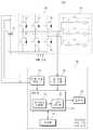
도 1은 본 발명의 일 실시예에 따른 영구자석 모터고장진단시스템을 설명하기 위한 블록도이다.
도 2는 본 발명의 일 실시예에 따른 영구자석 모터고장진단시스템을 설명하기 위한 개략도이다.
도 3은 본 발명의 일 실시예에 따른 영구자석 모터 및 인버터의 등가회로를 설명하기 위한 회로도이다.
도 4는 도 3의 등가회로에 대한 상전압 및 상전류 파형을 설명하기 위한 그래프이다.
도 5는 도 3의 등가회로에서 v상 전류에 대한 천이상태를 설명하기 위한 회로도이다.
도 6은 도 5의 등가회로에서 상전환에 대한 상전류 파형을 설명하기 위한 그래프이다.
도 7은 도 6의 A영역을 확대하여 상전류 및 역기전력 파형을 설명하기 위한 그래프이다.
도 8은 본 발명의 일 실시예에 따른 영구자석 모터고장진단방법을 설명하기 위한 순서도이다.1 is a block diagram illustrating a fault diagnosis system for a permanent magnet motor according to an embodiment of the present invention.
2 is a schematic diagram for explaining a fault diagnosis system for a permanent magnet motor according to an embodiment of the present invention.
3 is a circuit diagram for explaining an equivalent circuit of a permanent magnet motor and an inverter according to an embodiment of the present invention.
4 is a graph for explaining a phase voltage and a phase current waveform for the equivalent circuit of FIG.
5 is a circuit diagram for explaining the transition state with respect to the v-phase current in the equivalent circuit of Fig.
6 is a graph for explaining a phase current waveform for phase change in the equivalent circuit of FIG.
FIG. 7 is a graph for explaining the phase current and the back electromotive force waveform by enlarging the area A in FIG.
8 is a flowchart illustrating a method for diagnosing a permanent magnet motor failure according to an embodiment of the present invention.
이하 본 발명의 실시예를 첨부된 도면들을 참조하여 상세히 설명한다. 우선 각 도면의 구성요소들에 참조부호를 부가함에 있어서, 동일한 구성요소들에 대해서는 비록 다른 도면상에 표시되더라도 가능한 한 동일한 부호를 가지도록 하고 있음에 유의한다. 또한 본 발명을 설명함에 있어, 관련된 공지 구성 또는 기능에 대한 구체적인 설명이 당업자에게 자명하거나 본 발명의 요지를 흐릴 수 있다고 판단되는 경우에는 그 상세한 설명은 생략한다.Hereinafter, embodiments of the present invention will be described in detail with reference to the accompanying drawings. In the drawings, the same reference numerals as used in the appended drawings denote like elements, unless indicated otherwise. In the following description of the present invention, a detailed description of known functions and configurations incorporated herein will be omitted when it may make the subject matter of the present invention rather obvious or understandable to those skilled in the art.
도 1은 본 발명의 일 실시예에 따른 영구자석 모터고장진단시스템을 설명하기 위한 블록도이고, 도 2는 본 발명의 일 실시예에 따른 영구자석 모터고장진단시스템을 설명하기 위한 개략도이다.FIG. 1 is a block diagram illustrating a system for diagnosing a permanent magnet motor failure according to an embodiment of the present invention. FIG. 2 is a schematic diagram for explaining a system for diagnosing a permanent magnet motor failure according to an embodiment of the present invention.
도 1 및 도 2를 참조하면, 영구자석 모터고장진단시스템(100)은 구형파로 구동되는 영구자석 모터(40)의 고장을 실시간으로 진단한다. 영구자석 모터고장진단시스템(100)은 영구자석 모터(40)의 고장유무 뿐만 아니라 고장 위치 및 고장 정도를 진단한다. 영구자석 모터고장진단시스템(100)은 인버터(20), 영구자석 모터 고장진단장치(30) 및 영구자석 모터(40)를 포함하고, 전원(10)을 더 포함할 수 있다.Referring to FIGS. 1 and 2, the permanent magnet motor
전원(10)은 일단이 인버터(20)와 연결되어 인버터(20)에 전압 및 전류를 공급하고, 타단이 그라운드(GND)와 연결된다. 전원(10)은 직류 전원을 공급하거나, 교류전원을 공급할 수 있다. 여기서, 전원부(10)가 인버터(20)에 교류 전원을 공급하는 경우, 전원(10)은 인버터(20)의 입력단에 정류회로(미도시)를 더 포함하여 교류전원이 직류전원으로 변환되도록 할 수 있다.One end of the
인버터(20)는 일단이 전원(10)과 연결되고, 타단이 영구자석 모터(40)와 연결되며, 복수의 스위칭 소자(21, 22, 23, 24, 25, 26)를 포함한다. 상세하게는, 인버터(20)는 제1 스위칭 소자(21), 제2 스위칭 소자(22), 제3 스위칭 소자(23), 제4 스위칭 소자(24), 제5 스위칭 소자(25) 및 제6 스위칭 소자(26)를 포함한다. 이 때, 인버터(20)는 3상 브릿지로 연결된다. 즉, 인버터(20)는 제1 스위칭 소자(21) 및 제2 스위칭 소자(22)가 브릿지로 연결되어 u상을 이루고, 제3 스위칭 소자(23) 및 제4 스위칭 소자(24)가 브릿지로 연결되어 v상을 이루며, 제5 스위칭 소자(25) 및 제6 스위칭 소자(26)가 브릿지로 연결되어 w상을 이룬다. 여기서, 스위칭 소자는 스위치 및 환류 다이오드를 포함한다. 인버터(20)는 제1 스위칭 소자(21) 내지 제6 스위칭 소자(26)의 온오프에 따라 출력전류 및 출력전압을 조절할 수 있으며, 조절된 출력전류 및 출력전압을 영구자석 모터(40)로 출력한다.The
영구자석 모터 고장진단장치(30)는 인버터(20)의 입력전류, 입력전압 및 영구자석 모터(40)의 상전환 시간을 이용하여 영구자석 모터(40)의 고정자에 대한 각 상의 인덕턴스를 산출한다. 영구자석 모터 고장진단장치(30)는 산출된 각 상의 인덕턴스와 각 상의 기준 인덕턴스를 비교하여 영구자석 모터(40)의 고장유무를 진단한다. 여기서, 기준 인덕턴스는 영구자석 모터(40)의 정상상태에서의 인덕턴스를 의미한다.The permanent magnet motor
상세하게는, 영구자석 모터 고장진단장치(30)는 전류 전압 측정부(31), 상전환 측정부(32) 및 제어부(33)를 포함하고, 출력부(36) 및 저장부(37)를 더 포함할 수 있다.More specifically, the permanent magnet motor
전류 전압 측정부(31)는 인버터(20)의 입력전류 및 입력전압을 측정한다. 전류 전압 측정부(31)는 인버터(20)의 입력단과 연결되어 전원(10)으로부터 입력되는 전류 및 전압을 측정한다. 이 때, 측정되는 입력전류 및 입력전압은 직류일 수 있다.The current-
상전환 시간 산출부(32)는 영구자석 모터(40)의 상전환에 대한 시작과 종료 사이의 상전환 시간을 산출한다. 상전환 시간 산출부(32)는 영구자석 모터(40)의 상전환 시작 시간 및 상전환 종료 시간을 각각 측정한 후, 상전환 종료 시간에서 상전환 시작 시간을 차감하여 상전환 시간을 산출한다.Phase switching
제어부(33)는 전류 전압 측정부(31)로부터 측정된 입력전류 및 입력전압과 상전환 시간 산출부(32)로부터 산출된 상전환 시간을 이용하여 영구자석 모터(40)의 고정자에 대한 각 상의 인덕턴스를 산출한다. 제어부(33)는 산출된 각 상의 인덕턴스와 영구자석 모터(40)의 기준 인덕턴스를 비교하여 영구자석 모터(40)의 고장유무를 진단한다. 제어부(33)는 인덕턴스 산출부(34) 및 고장 진단부(35)를 포함한다.The
인덕턴스 산출부(34)는 전류 전압 측정부(31)로부터 인버터(20)의 입력전류 및 입력전압을 입력받고, 상전환 시간 산출부(32)로부터 영구자석 모터(40)의 상전환 시간을 입력받는다. 인덕턴스 산출부(34)는 입력전류, 입력전압 및 상전환 시간을 기초로 영구자석 모터(40)의 전압방정식을 이용하여 고정자에 대한 각 상의 인덕턴스를 산출한다. 즉, 인덕턴스 산출부(34)는 영구자석 모터(40)의 u상, v상 및 w상에 대한 인덕턴스를 각각 산출한다.The
고장 진단부(35)는 인덕턴스 산출부(34)로부터 산출된 각 상에 대한 인덕턴스를 기준 인덕턴스와 비교하여 오차를 산출한다. 여기서, 기준 인덕턴스는 정상상태일 때 영구자석 모터(40)의 인덕턴스일 수 있다. 고장 진단부(35)는 산출된 오차가 정상범위에 포함되지 않는 상이 발생되면 해당 상에 권취된 코일이 단락된 것으로 실시간으로 진단한다. 즉, 영구자석 모터가 구동 중인 상태에서 고정자에 권취된 코일의 단락을 진단할 수 있다.The
상세하게는, 고장 진단부(35)는 실제로 영구자석 모터(40)의 단락 상태를 확인하지 않고도 인덕턴스의 값만으로 영구자석 모터(40)의 단락을 진단할 수 있다. 고장 진단부(35)는 단락이 발생된 상을 진단할 뿐만 아니라 오차의 크기를 통해 단락의 정도를 진단할 수 있다. 바람직하게는 고장 진단부(35)는 오차가 크면 클수록 단락의 정도가 큰 것으로 진단할 수 있다.In detail, the
출력부(36)는 인덕턴스 산출부(34)로부터 산출된 각 상에 대한 인덕턴스를 출력한다. 출력부(36)는 고장 진단부(35)로부터 진단된 고장유무를 출력한다. 출력부(36)는 액정, 모니터, 프린터, 프로젝터 등이 포함된 디스플레이이거나, 스피커, 경보등 등과 같은 알람장치일 수 있다.The
저장부(37)는 전류 전압 측정부(31)로부터 측정된 입력전류 및 입력전압이 저장된다. 저장부(37)는 상전환 시간 산출부(32)로부터 산출된 상전환 시간이 저장된다. 저장부(37)는 인덕턴스 산출부(34)로부터 산출된 각 상에 대한 인덕턴스가 저장된다. 저장부(37)는 고장 진단부(35)로부터 진단된 고장유무가 저장된다. 저장부(37)는 플래시 메모리 타입(flash memory type), 하드디스크 타입(hard disk type), 미디어 카드 마이크로 타입(multimedia card micro type), 카드 타입의 메모리(예를 들어 SD 또는 XD 메모리 등), 램(Random Access Memory, RAM), SRAM(Static Random Access Memory), 롬(Read-Only Memory, ROM), EEPROM(Electrically Erasable Programmable Read-Only Memory), PROM(Programmable Read-Only Memory), 자기메모리, 자기 디스크, 광디스크 중 적어도 하나의 저장매체를 포함할 수 있다.The
한편, 영구자석 모터 고장진단장치(30)는 전술된 바와 같이, 도 1 및 도 2에서 영구자석 모터(40)와 별개로 구비되는 구조로 도시되고, 설명되었지만 이에 한정하지 않고 영구자석 모터(40)의 내부에 있는 컨트롤러에 장착되는 구조일 수 있다.1 and 2, the permanent magnet motor
영구자석 모터(40)는 구형파로 구동되는 영구자석 모터이고, 부하(미도시)와 연결된다. 바람직하게는, 영구자석 모터(40)는 브러시리스 직류(Brushless DC, BLDC) 모터일 수 있다. 영구자석 모터(40)는 고정자(미도시) 및 회전자(미도시)를 포함한다. 고정자는 권선계좌의 3상(u, v, w)으로 구성되며, 3상의 고정자는 120°간격으로 배치되어 각 고정자에 흐르는 전류의 방향에 따라 자극(N극 또는 S극)으로 작용한다. 한편, 영구자석 모터(40)는 고정자에 코일이 Y결선 또는 △결선으로 권취될 수 있다.The
영구자석 모터(40)는 2상 여자 방식, 즉 3상의 고정자 중 두 상만 여자되고, 나머지 한 상은 여자되지 않는 방식으로 회전자를 회전시킬 수 있다. 이 때, 영구자석 모터(40)는 각 상마다 저항(R), 인덕터(L) 및 역기전력(e)을 포함한다.The
도 3은 본 발명의 일 실시예에 따른 영구자석 모터 및 인버터의 등가회로를 설명하기 위한 회로도이고, 도 4는 도 3의 등가회로에 대한 상전압 및 상전류 파형을 설명하기 위한 그래프이며, 도 5는 도 3의 등가회로에서 v상 전류에 대한 천이상태를 설명하기 위한 회로도이고, 도 6은 도 5의 등가회로에서 상전환에 대한 상전류 파형을 설명하기 위한 그래프이며, 도 7은 도 6의 A영역을 확대하여 상전류 및 역기전력 파형을 설명하기 위한 그래프이다.FIG. 3 is a circuit diagram for explaining an equivalent circuit of a permanent magnet motor and an inverter according to an embodiment of the present invention. FIG. 4 is a graph for explaining a phase voltage and a phase current waveform for the equivalent circuit of FIG. 6 is a graph for explaining the phase current waveform for the phase change in the equivalent circuit of Fig. 5, and Fig. 7 is a graph for explaining the phase current for the v phase current in the equivalent circuit of Fig. 6 Is a graph for explaining the phase current and the back electromotive force waveform.
도 2 내지 도 7을 참조하면, 영구자석 모터 고장진단장치(30)는 영구자석 모터(40)의 이웃한 코일간 단락을 발생초기에 진단함으로써, 사용자가 신속한 대처를 할 수 있다. 이를 통해, 영구자석 모터 고장진단장치(30)는 영구자석 모터(40)가 단락으로 발생될 수 있는 성능저하, 파괴 또는 화재 등을 미연에 방지할 수 있다.Referring to Figs. 2 to 7, the permanent magnet motor
영구자석 모터(40) 및 인버터(20)의 등가회로(도 3)는 각 상의 정현파 역기전력을 [수학식 1]과 같이 나타내고, 구형파 구동시 상전압 및 상전류의 파형을 도 4와 같이 나타낸다.The equivalent circuit (FIG. 3) of the

여기서, eu는 영구자석 모터(40)의 u상 역기전력을 의미하고, ev는 영구자석 모터(40)의 v상 역기전력을 의미하며, ew는 영구자석 모터(40)의 w상 역기전력을 의미하고, E는 영구자석 모터(40)의 역기전력을 의미하며, w는 전기각속도를 의미한다.Here, eu is the u refers to the counter electromotive force and, ev of the
따라서, 영구자석 모터(40)의 역기전력 및 스위칭 패턴은 전기각 60°의 구간 동안 일정한 스위칭 패턴이 유지된다.Therefore, the counter electromotive force and the switching pattern of the
예를 들면, u상과 w상이 여자되고, v상이 개방되는 0°< wt < 60°구간인 경우, 인버터(20)는 제1 스위칭 소자(21)가 PWM 신호에 따라 온 또는 오프 상태가 되고, 제6 스위칭 소자(26)가 항상 온 상태가 되며, 나머지 스위칭 소자(22, 23, 24, 25)가 모두 오프 상태가 된다. 즉, 인버터(20)는 PWM 신호 상태, 개방된 상의 환류 다이오드의 도통 상태에 따라 4가지 종류로 구분될 수 있다.For example, when the u-phase and the w-phase are excited and the v-phase is 0 ° <wt <60 °, the
이하, 해석의 편의상 전류 및 전압 방정식에서는 스위치와 환류 다이오드가 이상적인 것으로 가정하여 이들이 도통되었을 때의 전압 강하가 발생되지 않는다고 간주한다.Hereinafter, for convenience of the analysis, the current and voltage equations assume that the switch and the reflux diode are ideal, and assume that no voltage drop occurs when they are conducted.
먼저, wt가 0°일 때, 인버터(20)는 v상을 소호하고, w상을 점호하여도 인덕턴스 성분으로 인하여 소호된 상의 전류는 순간적으로 0이 되지 못하고, 제2 스위칭 소자(22)의 환류 다이오드를 통하여 흐르면서 일정 기울기로 감소한다. 즉, v상의 전류가 완전히 소호되기 전까지의 등가회로(도 5)는 v상의 단자전압이 PWM 신호의 온오프 상태와 관계없이 항상 전원(10)의 전압(Vdc)으로 검출되며, [수학식 2]와 같이 나타낸다.First, if wt is 0 °,

여기서, vvn은 인버터(20)의 v상 단자전압을 의미하고, Vdc는 전원(10)의 전압을 의미한다.Here, vvn denotes the v-phase terminal voltage of the
이로 인해, 도 5의 등가회로는 [수학식 3] 내지 [수학식 5]와 같이 나타낸다.Thus, the equivalent circuit of FIG. 5 is expressed by Equations (3) to (5).

여기서, iu는 영구자석 모터(40)의 u상 상전류를 의미하고, iv는 영구자석 모터(40)의 v상 상전류를 의미하며, iw는 영구자석 모터(40)의 w상 상전류를 의미한다.Here, iu denotes the u phase phase current of the


여기서, vus는 영구자석 모터(40)의 u상 상전압을 의미하고, vvs는 영구자석 모터(40)의 v상 상전압을 의미하며, vws는 영구자석 모터(40)의 w상 상전압을 의미한다.Here, vus means a u-phase-phase voltage of the
따라서, 영구자석 모터(40)의 전압방정식은 [수학식 6]과 같이 정리되며, 인덕턴스 산출부(34)는 [수학식 6]으로부터 도출된 수학식을 이용하여 각 상에 대한 인덕턴스를 산출할 수 있다. 이하, [수학식 6]을 기초로 인덕턴스 산출부(34)가 각 상에 대한 인덕턴스를 산출하기 위한 수학식을 도출하는 과정을 상세하게 설명한다.Therefore, the voltage equation of the

여기서, R은 영구자석 모터(40)의 저항을 의미하고, L1, L2, L3은 영구자석 모터(40)의 각 상에 대한 인덕턴스를 의미한다.Here, R denotes the resistance of the
[수학식 4] 및 [수학식 5]는 [수학식 6]을 이용하여 [수학식 7] 및 [수학식 8]과 같이 정리된다.[Equation 4] and [Equation 5] are summarized as [Equation 7] and [Equation 8] using


[수학식 7] 및 [수학식 8]을 이용하여 [수학식 9]와 같은 관계식을 도출한다.Using Equation (7) and Equation (8), a relational expression such as Equation (9) is derived.

한편, 중성점전압인 vs는 w상 상전압인 vws 및 [수학식 3]을 이용하여 [수학식 10]과 같이 나타낼 수 있다.On the other hand, the voltage vs , which is the neutral point voltage, can be expressed by Equation (10) using the w w phase voltage vws and Equation (3).

L = L1 = L2로 가정하면 [수학식 10]은 [수학식 11]과 같이 정리된다.Assuming that L = L < 1 > = L < 2 >, Equation (10) is summarized as Equation (11).

여기서, 영구자석 모터(40)의 전압방정식인 [수학식 6]은 [수학식 10] 및 [수학식 11]을 이용하여 [수학식 12]와 같이 정리된다.Here, the voltage equation of the

한편, 도 6의 A영역이 확대된 도 7은 영구자석 모터(40)의 상전환일 때, 상전류와 역기전력이 도시된다. 이 때, t1은 상전환의 시작시간을 의미하고, t2는 상전환의 종료시간을 의미한다. 또한 I2 및 I3은 상전환 시작 및 종료시 상전류의 크기를 의미한다. 여기서, 상전환 시 각각의 상전류는 선형적으로 증가와 감소하는 것으로 가정하였다.On the other hand, Fig. 7 in which the area A in Fig. 6 is enlarged shows phase current and counter electromotive force when the phase of the
상전환 시, 전압방정식인 [수학식 12]를 이용하여 [수학식 13] 내지 [수학식 15]로 나타낼 수 있다.(13) to (15) using the voltage equation (12).


여기서, D는 인버터(200)의 PWM 듀티비를 의미한다.Here, D means the PWM duty ratio of the inverter 200. [
[수학식 13] 내지 [수학식 15]를 다시 정리하면, [수학식 16] 내지 [수학식 18]과 같이 나타낼 수 있다.The following equations (13) to (15) can be rewritten as Equation (16) to Equation (18).


한편, [수학식 16]에서의 저항(R)은 작기 때문에 무시하고, 상전환 시간은 짧기 때문에 상전환 시의 역기전력의 변화가 직선형태라고 가정하면, [수학식 19]와 같이 정리된다.On the other hand, assuming that the resistance R in Equation (16) is small and the changeover time is short and the change of the counter electromotive force at the time of phase change is linear, it is summarized as in Equation (19).

즉, 상전환 시간 t2 t1은 상전환 시간 산출부(32)에서 산출하고, 입력전압(Vdc), I3, I2는 전류 전압 측정부(31)에서 측정함으로, 인덕턴스 산출부(34)는 입력전압, 입력전류 및 상전환 시간을 이용하여 한 상의 인덕턴스를 산출할 수 있다. 여기서, I2는 상전환 시작 시의 상전류로써, 상전환 시작 때의 입력전류와 동일하여 Idc_s로 나타내고, I3은 상전환 종류 시의 상전류로써, 상전환 종류 때의 입력전류와 동일하여 Idc_e로 나타낸다. 따라서, [수학식 19]는 [수학식 20]과 같이 정리된다.That is, the phase change time t2 t1 is calculated by the phase change

여기서, Ln은 각 상의 인덕턴스를 의미하고, n은 1~3이다.Here, Ln denotes the inductance of each phase, and n is 1 to 3.
인덕턴스 산출부(34)는 각 구간에서 L1, L2및 L3을 각각 산출할 수 있다. 여기서, 각 구간은 전기각 1회전시 발생되는 6개의 구간을 의미한다.The
고장 진단부(33)는 인덕턴스 산출부(34)로부터 산출된 각 상의 인덕턴스를 기준 인덕턴스와 비교하여 오차를 산출한다. 고장 진단부(33)는 오차가 정상범위에 포함되면 단락이 없는 것으로 진단하고, 오차가 정상범위에 포함되지 않으면 포함되지 않는 상에 권취된 코일이 단락된 것으로 진단한다. 고장 진단부(33)는 코일의 단락이 발생된 상을 진단할 뿐만 아니라 코일의 단락 정도를 진단할 수 있다. 즉, 고장 진단부(33)는 오차가 크면 클수록 단락의 정도가 큰 것으로 진단할 수 있다. 바람직하게는, 고장 진단부(33)는 설정된 범위를 기준으로 단락의 정도를 차등 구분하여 각 등급에 해당하는 경고 알람신호를 생성할 수 있다.The
예를 들면, 고장 진단부(33)는 주의, 경보 및 위험과 같이 3단계로 차등 구분할 수 있다. 이 때, 주의 단계는 단락의 초기 단계로써, 고장 진단부(33)는 현재 영구자석 모터(40)의 구동을 종료한 후 유지보수를 제안하는 경고 알람신호를 생성할 수 있다. 경보 단계는 단락의 정도가 일정부분 확장된 단계로써, 고장 진단부(33)는 현재 영구자석 모터(40)의 구동을 종료시키고 유지보수를 제안하는 경고 알람신호를 생성할 수 있다. 위험 단계는 단락의 정도가 전방위로 확장되어 영구자석 모터(40)가 파괴되거나 화재가 발생될 위험이 있는 단계로써, 고장 진단부(33)는 현재 영구자석 모터(40)의 구동을 강제 종료시키는 경고 알림신호를 생성할 수 있다.For example, the
도 8은 본 발명의 일 실시예에 따른 영구자석 모터고장진단방법을 설명하기 위한 순서도이다.8 is a flowchart illustrating a method for diagnosing a permanent magnet motor failure according to an embodiment of the present invention.
도 2 및 도 8을 참조하면, 영구자석 모터고장진단방법은 구형파로 구동되는 영구자석 모터(40)의 각 상에 대한 인덕턴스를 산출하고, 산출된 각 상의 인덕턴스와 기준 인덕턴스를 비교하여 영구자석 모터(40)의 고장을 실시간으로 진단할 수 있다. 영구자석 모터고장진단방법은 각 상의 인덕턴스와 기준 인덕턴스의 오차가 정상범위에 포함되지 않는 상이 발생되면 해당 상에 권취된 코일이 단락된 것으로 진단하고, 각 상의 인덕턴스와 기준 인덕턴스의 오차가 크면 클수록 단락의 정도가 큰 것으로 진단할 수 있다.Referring to FIGS. 2 and 8, the method for diagnosing a permanent magnet motor failure includes calculating an inductance of each phase of a
S51단계에서, 영구자석 모터 고장진단장치(30)는 구형파로 구동되는 영구자석 모터(40)와 연결된 인버터(20)의 입력전류 및 입력전압을 측정한다. 영구자석 모터 고장진단장치(30)는 인버터(20)의 입력단과 연결된 전원(10)으로부터 입력되는 전류 및 전압을 측정한다.In step S51, the permanent magnet motor
S53단계에서, 영구자석 모터 고장진단장치(30)는 영구자석 모터(40)의 상전환에 대한 시작과 종료 사이의 상전환 시간을 산출한다. 영구자석 모터 고장진단장치(30)는 상전환 시작 시간 및 상전화 종료 시간을 각각 측정한 후, 상전환 종료 시간에서 상전환 시작 시간을 차감하여 상전환 시간을 산출한다.In step S53, the permanent magnet motor
S55단계에서, 영구자석 모터 고장진단장치(30)는 입력전류, 입력전압 및 상전환 시간을 이용하여 영구자석 모터(40)의 고정자에 대한 각 상의 인덕턴스를 산출한다. 영구자석 모터 고장진단장치(30)는 영구자석 모터(40)의 전압방정식을 이용하여 고장자에 대한 각 상의 인덕턴스를 산출한다. 즉, 영구자석 모터 고장진단장치(30)는 영구자석 모터(40)의 u상, v상 및 w 상에 대한 인덕턴스를 실시간 산출한다.In step S55, the permanent magnet motor
S57단계에서, 영구자석 모터 고장진단장치(30)는 산출된 각 상의 인덕턴스와 영구자석 모터(40)의 기준 인덕턴스를 비교하여 영구자석 모터(40)의 고장유무를 진단한다. 이 때, 영구자석 모터 고장진단장치(30)는 각 상에 대한 인덕턴스와 기준 인덕턴스의 오차를 산출한다. 영구자석 모터 고장진단장치(30)는 산출된 오차가 정상범위에 포함되면 단락이 발생하지 않은 것으로 진단하고, 정상범위에 포함되지 않으면 단락이 발생된 것으로 진단한다. 또한 영구자석 모터 고장진단장치(30)는 오차의 크기를 통해 단락의 정도를 진단한다. 바람직하게는, 영구자석 모터 고장진단장치(30)는 오차가 크면 클수록 단락의 정도가 큰 것으로 진단할 수 있다.In step S57, the permanent magnet motor
이상에서 본 발명의 바람직한 실시예에 대해 도시하고 설명하였으나, 본 발명은 상술한 특정의 바람직한 실시예에 한정되지 아니하며, 청구범위에서 청구하는 본 발명의 요지를 벗어남이 없이 당해 발명이 속하는 기술분야에서 통상의 지식을 가진 자라면 누구든지 다양한 변형 실시가 가능한 것은 물론이고, 그와 같은 변경은 청구범위 기재의 범위 내에 있게 된다.While the present invention has been particularly shown and described with reference to exemplary embodiments thereof, it is clearly understood that the same is by way of illustration and example only and is not to be taken by way of limitation in the embodiment in which said invention is directed. It will be understood by those skilled in the art that various changes in form and detail may be made therein without departing from the scope of the appended claims.
10: 전원
20: 인버터
21: 제1 스위칭 소자
22: 제2 스위칭 소자
23: 제3 스위칭 소자
24: 제4 스위칭 소자
25: 제5 스위칭 소자
26: 제6 스위칭 소자
30: 영구자석 모터 고장진단장치
31: 전류 전압 측정부
32: 상전환 시간 산출부
33: 제어부
34: 인덕턴스 산출부
35: 고장 진단부
36: 출력부
37: 저장부
40: 영구자석 모터
100: 영구자석 모터 고장진단시스템10: Power supply
20: Inverter
21: first switching element
22: second switching element
23: Third switching element
24: fourth switching element
25: fifth switching element
26: Sixth switching element
30: Permanent magnet motor fault diagnosis device
31: Current voltage measurement unit
32: Phase change time calculation unit
33:
34: Inductance calculation unit
35: Fault diagnosis part
36: Output section
37:
40: permanent magnet motor
100: Permanent magnet motor fault diagnosis system
Claims (10)
Translated fromKorean상기 영구자석 모터의 상전환에 대한 시작과 종료 사이의 상전환 시간을 산출하는 상전환 시간 산출부; 및
상기 전류 전압 측정부로부터 측정된 입력전류 및 입력전압과 상기 상전환 시간 산출부로부터 산출된 상전환 시간을 이용하여 상기 영구자석 모터의 고정자에 대한 각 상의 인덕턴스를 산출하고, 상기 산출된 각 상의 인덕턴스와 각 상의 기준 인덕턴스를 비교하여 상기 영구자석 모터의 코일 단락에 대한 고장유무를 진단하는 제어부;
를 포함하는 영구자석 모터 고장진단장치.A current voltage measuring unit for measuring an input current and an input voltage of an inverter connected to a permanent magnet motor driven by a square wave;
A phase change time calculating unit for calculating an phase change time between a start and an end of the phase change of the permanent magnet motor; And
Calculating an inductance of each phase to the stator of the permanent magnet motor by using the input current and the input voltage measured from the current voltage measurement unit and the phase change time calculated from the phase change time calculation unit, And comparing the reference inductance of each phase with the reference inductance of each phase to diagnose the failure of the permanent magnet motor against a short circuit of the coil.
The permanent magnet motor fault diagnosis apparatus comprising:
상기 제어부는,
상기 입력전류, 상기 입력전압 및 상기 상전환 시간을 기초로 상기 영구자석 모터의 전압방정식을 이용하여 상기 고정자에 대한 각 상의 인덕턴스를 산출하는 인덕턴스 산출부; 및
상기 인덕턴스 산출부로부터 산출된 각 상의 인덕턴스를 각 상의 기준 인덕턴스와 비교하여 오차를 산출하고, 상기 오차가 정상범위에 포함되지 않는 상이 발생되면 해당 상에 권취된 코일이 단락된 것으로 진단하는 고장 진단부;
를 포함하는 것을 특징으로 하는 영구자석 모터 고장진단장치.The method according to claim 1,
Wherein,
An inductance calculating unit for calculating an inductance of each phase of the stator using the voltage equation of the permanent magnet motor based on the input current, the input voltage, and the phase change time; And
A fault diagnosis unit for comparing the inductance of each phase calculated by the inductance calculation unit with a reference inductance of each phase to calculate an error and diagnosing that the coil wound on the phase is short- ;
The permanent magnet motor fault diagnosis apparatus comprising:
상기 인덕턴스 산출부는,
상기 전압방정식을 하기 수학식 1로 나타내는 것을 특징으로 하는 영구자석 모터 고장진단장치.
[수학식 1]

(여기서, vus는 영구자석 모터의 u상 상전압을 의미하고, vvs는 영구자석 모터의 v상 상전압을 의미하며, vws는 영구자석 모터의 w상 상전압을 의미하고, iu는 영구자석 모터의 u상 상전류를 의미하며, iv는 영구자석 모터의 v상 상전류를 의미하고, iw는 영구자석 모터의 w상 상전류를 의미하며, L1은 영구자석 모터의 u상 인덕턴스를 의미하고, L2는 영구자석 모터의 v상 인덕턴스를 의미하며, L3은 영구자석 모터의 w상 인덕턴스를 의미하고, eu는 영구자석 모터의 u상 역기전력을 의미하며, ev는 영구자석 모터의 v상 역기전력을 의미하고, ew는 영구자석 모터의 w상 역기전력을 의미하며, R은 영구자석 모터의 저항을 의미함)3. The method of claim 2,
Wherein the inductance calculating unit comprises:
Wherein the voltage equation is expressed by the following equation (1): " (1) "
[Equation 1]
(Where vus means the u phase phase voltage of the permanent magnet motor, vvs the v phase voltage of the permanent magnet motor, vws the w phase voltage of the permanent magnet motor, iu is means a u-phase phase current of the permanent magnet motor, iv refers to the v-phase phase current of the permanent magnet motor and, iw represents a w-phase phase current of the permanent magnet motor and, L1 is a u-phase inductance of the permanent magnet motor refers to, and L2 is means a v-phase inductance of the permanent magnet motor, L3 denotes a w-phase inductance of the permanent magnet motor, and eu denotes the u-phase counter-electromotive force of the permanent magnet motor and, ev is permanent It means a v-phase counter-electromotive force of the magnet motor and, ew denotes the w-phase counter-electromotive force of the permanent magnet motor, and, R a indicates the resistance of the permanent magnet motor)
상기 인덕턴스 산출부는,
상기 수학식 1을 기초로 도출된 하기 수학식 2를 이용하여 상기 영구자석 모터의 고정자에 대한 각 상의 인덕턴스를 산출하는 것을 특징으로 하는 영구자석 모터 고장진단장치.
[수학식 2]

(여기서, Ln은 각 상의 인덕턴스를 의미하고, n은 1~3이며, t2-t1은 상전환시간을 의미하고, t1은 상전환의 시작 시간을 의미하고, t2는 상전환의 종료 시간을 의미하며, D는 PWM의 듀티비를 의미하고, Vdc는 입력전압을 의미하며, E는 역기전력을 의미하고, Idc_s는 상전환 시작시의 입력전류를 의미하며, Idc_e는 상전환 종료시의 입력전류를 의미함)The method of claim 3,
Wherein the inductance calculating unit comprises:
Wherein the inductance of each phase of the permanent magnet motor relative to the stator is calculated using Equation (2) derived from Equation (1).
&Quot; (2) "
(Where, Ln denotes the inductance of each phase and, n is1 ~ 3, t2 -t 1 means a phase transition time, and t1 denotes the start time of phase inversion, and t2 is the conversion end represents the time, and D means the duty ratio of the PWM, and, Vdc denotes the input voltage, and E denotes a counter-electromotive force and, Idc_s refers to the input current in the phase inversion starts, Idc_e is Quot; means the input current at the end of the phase change)
상기 고장 진단부는,
상기 오차가 크면 클수록 상기 단락의 정도가 큰 것으로 진단하는 것을 특징으로 하는 영구자석 모터 고장진단장치.3. The method of claim 2,
The fault diagnosis unit,
And diagnoses that the degree of the short circuit is larger as the error is larger.
상기 고장 진단부는,
상기 단락이 발생되면, 상기 단락의 정도를 차등 구분하여 각 등급에 해당하는 경고 알람신호를 생성하는 것을 특징으로 하는 영구자석 모터 고장진단장치.6. The method of claim 5,
The fault diagnosis unit,
And generates a warning alarm signal corresponding to each class by classifying the degree of the short circuit when the short circuit occurs.
상기 고장 진단부는,
상기 영구자석 모터가 구동 중인 상태에서 상기 권취된 코일의 단락을 진단하는 것을 특징으로 하는 영구자석 모터 고장진단장치.3. The method of claim 2,
The fault diagnosis unit,
And diagnoses a short-circuit of the wound-up coil when the permanent magnet motor is in operation.
상기 영구자석 모터는,
상기 고정자에 상기 코일이 Y결선 또는 △결선으로 권취되는 것을 특징으로 하는 영구자석 모터 고장진단장치.The method according to claim 1,
The permanent magnet motor includes:
And the coil is wound on the stator in Y wiring or? Wiring.
3상 브릿지로 연결된 복수의 스위칭 소자를 포함하고, 상기 복수의 스위칭 소자가 온오프(on/off)되면서 발생되는 출력전류 및 출력전압을 상기 영구자석 모터로 출력하는 인버터; 및
상기 인버터의 입력전류 및 입력전압을 측정하는 전류 전압 측정부, 상기 영구자석 모터의 상전환에 대한 시작과 종료 사이의 상전환 시간을 산출하는 상전환 시간 산출부, 및 상기 전류 전압 측정부로부터 측정된 입력전류 및 입력전압과 상기 상전환 시간 산출부로부터 산출된 상전환 시간을 이용하여 상기 영구자석 모터의 고정자에 대한 각 상의 인덕턴스를 산출하고, 상기 산출된 각 상의 인덕턴스와 각 상의 기준 인덕턴스를 비교하여 상기 영구자석 모터의 코일 단락에 대한 고장유무를 진단하는 제어부를 포함하는 영구자석 모터 고장진단장치;
를 포함하는 영구자석 모터 고장진단시스템.A permanent magnet motor driven by a square wave;
An inverter that includes a plurality of switching elements connected by a three-phase bridge, and outputs an output current and an output voltage generated when the plurality of switching elements are turned on / off to the permanent magnet motor; And
A phase changeover time calculating section for calculating an phase change time between the start and the end of the phase change of the permanent magnet motor; Calculating an inductance of each phase with respect to the stator of the permanent magnet motor by using the input current and the input voltage, and the phase change time calculated from the phase change time calculating unit, and comparing the calculated inductance of each phase and the reference inductance of each phase And a controller for diagnosing whether or not the permanent magnet motor is faulty due to a short circuit of the coil.
A permanent magnet motor fault diagnosis system.
상기 영구자석 모터 고장진단장치가 상기 영구자석 모터의 상전환에 대한 시작과 종료 사이의 상전환 시간을 산출하는 단계;
상기 영구자석 모터 고장진단장치가 상기 측정된 입력전류 및 입력전압과 상기 산출된 상전환 시간을 이용하여 상기 영구자석 모터의 고정자에 대한 각 상의 인덕턴스를 산출하는 단계; 및
상기 영구자석 모터 고장진단장치가 상기 산출된 각 상의 인덕턴스와 각 상의 기준 인덕턴스를 비교하여 상기 영구자석 모터의 코일 단락에 대한 고장유무를 진단하는 단계;
를 포함하는 영구자석 모터 고장진단방법.
Measuring an input current and an input voltage of an inverter connected to a permanent magnet motor driven by a square wave of the permanent magnet motor fault diagnosis apparatus;
Calculating the phase change time between the start and the end of the phase change of the permanent magnet motor by the permanent magnet motor fault diagnosis apparatus;
Calculating the inductance of each phase with respect to the stator of the permanent magnet motor using the measured input current and input voltage and the calculated phase change time; And
Comparing the calculated inductance of each phase and the reference inductance of each phase by the permanent magnet motor fault diagnosis apparatus to diagnose whether the permanent magnet motor is faulty with respect to a short circuit of the coil;
The method comprising the steps of:
Priority Applications (2)
| Application Number | Priority Date | Filing Date | Title |
|---|---|---|---|
| KR1020170044620AKR101818916B1 (en) | 2017-04-06 | 2017-04-06 | Fault diagnosis apparatus, system and method of permanent magnet motor |
| US15/660,140US10374532B2 (en) | 2017-04-06 | 2017-07-26 | Apparatus, system and method of fault diagnosis for permanent magnet motor |
Applications Claiming Priority (1)
| Application Number | Priority Date | Filing Date | Title |
|---|---|---|---|
| KR1020170044620AKR101818916B1 (en) | 2017-04-06 | 2017-04-06 | Fault diagnosis apparatus, system and method of permanent magnet motor |
Publications (1)
| Publication Number | Publication Date |
|---|---|
| KR101818916B1true KR101818916B1 (en) | 2018-03-02 |
Family
ID=61729226
Family Applications (1)
| Application Number | Title | Priority Date | Filing Date |
|---|---|---|---|
| KR1020170044620AActiveKR101818916B1 (en) | 2017-04-06 | 2017-04-06 | Fault diagnosis apparatus, system and method of permanent magnet motor |
Country Status (2)
| Country | Link |
|---|---|
| US (1) | US10374532B2 (en) |
| KR (1) | KR101818916B1 (en) |
Cited By (6)
| Publication number | Priority date | Publication date | Assignee | Title |
|---|---|---|---|---|
| CN109188177A (en)* | 2018-10-01 | 2019-01-11 | 徐州中矿大传动与自动化有限公司 | A kind of high-power NPC three-level inverter short circuit current on-line detecting system |
| JP2020018063A (en)* | 2018-07-24 | 2020-01-30 | ファナック株式会社 | Motor controller and method for controlling motor |
| KR102086132B1 (en) | 2018-10-01 | 2020-03-06 | 현대오트론 주식회사 | Motor controller and short circuit diagnosis method thereof |
| CN112731204A (en)* | 2020-12-29 | 2021-04-30 | 哈尔滨宇龙自动化有限公司 | Permanent magnet synchronous motor turn-to-turn short circuit fault positioning detection control method |
| KR20230050659A (en)* | 2021-10-08 | 2023-04-17 | 인천대학교 산학협력단 | Apparatus and Method for Diagnosing Motor Fault Using Back Electromotive Force of Brushless DC Motor |
| WO2025013983A1 (en)* | 2023-07-11 | 2025-01-16 | 주식회사 비에스이 | Method for inspecting defect in micro speaker |
Families Citing this family (8)
| Publication number | Priority date | Publication date | Assignee | Title |
|---|---|---|---|---|
| EP3396854B1 (en)* | 2015-12-21 | 2019-12-11 | Nissan Motor Co., Ltd. | Motor diagnostic method and electric power conversion equipment using same |
| CN109633416A (en)* | 2018-12-29 | 2019-04-16 | 深圳开立生物医疗科技股份有限公司 | A kind of detection method of stepper motor driving circuit, apparatus and system |
| CN110208642B (en)* | 2019-05-22 | 2021-08-10 | 中南大学 | Method and system for simulating degradation process of turn-to-turn short circuit fault of stator of permanent magnet synchronous motor |
| CN112083349B (en)* | 2020-08-01 | 2023-04-07 | 南通长江电器实业有限公司 | Method for diagnosing turn-to-turn short circuit fault of stator winding of permanent magnet synchronous motor |
| CN111880097B (en)* | 2020-08-27 | 2023-04-28 | 中车青岛四方车辆研究所有限公司 | Three-phase symmetrical short-circuit fault detection method for train traction motor |
| CN114244196B (en)* | 2021-11-08 | 2024-09-27 | 江苏科技大学 | A fault-tolerant control method for Hall sensor of permanent magnet synchronous motor |
| CN114325380B (en)* | 2021-11-25 | 2022-12-27 | 合肥工业大学 | Fault diagnosis method for permanent magnet synchronous motor driving system |
| US12283910B2 (en) | 2022-12-05 | 2025-04-22 | Woodward, Inc. | Model-based health monitoring of electric motors |
Citations (4)
| Publication number | Priority date | Publication date | Assignee | Title |
|---|---|---|---|---|
| KR100925148B1 (en) | 2007-11-28 | 2009-11-05 | 고려대학교 산학협력단 | Means and apparatus for diagnosing a failure of a three-phase AC motor, and a medium having a computer readable program for executing the method. |
| JP2012215514A (en) | 2011-04-01 | 2012-11-08 | Keisokuki Center:Kk | Test device and test method |
| KR101357828B1 (en) | 2012-12-07 | 2014-02-05 | 전자부품연구원 | Fault detection method type of series permanent magnet motor and system using the same |
| EP2808999A1 (en) | 2012-01-27 | 2014-12-03 | Mitsubishi Electric Corporation | Motor control device and electric power steering device |
Family Cites Families (3)
| Publication number | Priority date | Publication date | Assignee | Title |
|---|---|---|---|---|
| JP6125295B2 (en)* | 2012-10-19 | 2017-05-10 | 三菱重工業株式会社 | Motor drive device and discharge control method thereof |
| KR101357827B1 (en)* | 2012-12-07 | 2014-02-05 | 전자부품연구원 | Fault detection method type of parallel permanent magnet motor and system using the same |
| US20150270747A1 (en)* | 2014-03-24 | 2015-09-24 | The Texas A&M University System | System and method for controlling multiphase electric motors |
- 2017
- 2017-04-06KRKR1020170044620Apatent/KR101818916B1/enactiveActive
- 2017-07-26USUS15/660,140patent/US10374532B2/enactiveActive
Patent Citations (4)
| Publication number | Priority date | Publication date | Assignee | Title |
|---|---|---|---|---|
| KR100925148B1 (en) | 2007-11-28 | 2009-11-05 | 고려대학교 산학협력단 | Means and apparatus for diagnosing a failure of a three-phase AC motor, and a medium having a computer readable program for executing the method. |
| JP2012215514A (en) | 2011-04-01 | 2012-11-08 | Keisokuki Center:Kk | Test device and test method |
| EP2808999A1 (en) | 2012-01-27 | 2014-12-03 | Mitsubishi Electric Corporation | Motor control device and electric power steering device |
| KR101357828B1 (en) | 2012-12-07 | 2014-02-05 | 전자부품연구원 | Fault detection method type of series permanent magnet motor and system using the same |
Cited By (8)
| Publication number | Priority date | Publication date | Assignee | Title |
|---|---|---|---|---|
| JP2020018063A (en)* | 2018-07-24 | 2020-01-30 | ファナック株式会社 | Motor controller and method for controlling motor |
| CN109188177A (en)* | 2018-10-01 | 2019-01-11 | 徐州中矿大传动与自动化有限公司 | A kind of high-power NPC three-level inverter short circuit current on-line detecting system |
| KR102086132B1 (en) | 2018-10-01 | 2020-03-06 | 현대오트론 주식회사 | Motor controller and short circuit diagnosis method thereof |
| CN109188177B (en)* | 2018-10-01 | 2023-12-19 | 江苏国传电气有限公司 | High-power NPC three-level inverter short-circuit current on-line detection system |
| CN112731204A (en)* | 2020-12-29 | 2021-04-30 | 哈尔滨宇龙自动化有限公司 | Permanent magnet synchronous motor turn-to-turn short circuit fault positioning detection control method |
| KR20230050659A (en)* | 2021-10-08 | 2023-04-17 | 인천대학교 산학협력단 | Apparatus and Method for Diagnosing Motor Fault Using Back Electromotive Force of Brushless DC Motor |
| KR102695989B1 (en)* | 2021-10-08 | 2024-08-16 | 인천대학교 산학협력단 | Apparatus and Method for Diagnosing Motor Fault Using Back Electromotive Force of Brushless DC Motor |
| WO2025013983A1 (en)* | 2023-07-11 | 2025-01-16 | 주식회사 비에스이 | Method for inspecting defect in micro speaker |
Also Published As
| Publication number | Publication date |
|---|---|
| US20180294751A1 (en) | 2018-10-11 |
| US10374532B2 (en) | 2019-08-06 |
Similar Documents
| Publication | Publication Date | Title |
|---|---|---|
| KR101818916B1 (en) | Fault diagnosis apparatus, system and method of permanent magnet motor | |
| JP5065192B2 (en) | Motor control apparatus and motor insulation deterioration detection method | |
| KR101357828B1 (en) | Fault detection method type of series permanent magnet motor and system using the same | |
| JP4254738B2 (en) | Power generation control device for vehicle generator | |
| JP5606387B2 (en) | Motor control apparatus and motor insulation deterioration detection method | |
| KR101357827B1 (en) | Fault detection method type of parallel permanent magnet motor and system using the same | |
| US9983253B2 (en) | Method and apparatus for identifying the winding short of bar wound electric machine at standstill condition | |
| US8593093B2 (en) | Electric motor control apparatus | |
| CN106961230B (en) | Motor control device | |
| JP6516878B2 (en) | Motor controller | |
| CN103941114B (en) | The self checking method of automobile permanent magnet synchronous motor system power module and current sensor | |
| JP2012233826A5 (en) | ||
| CN109951135B (en) | Power control unit | |
| CN107800333B (en) | Motor control device | |
| US9350277B2 (en) | Method of estimating voltage of input terminal of inverter and motor control method using the same | |
| US20110089883A1 (en) | Motor phase winding fault detection method and apparatus | |
| KR20150078460A (en) | Voltage sensor default detecting method | |
| KR20070021573A (en) | Motor control device, its control method and fault detection device of inverter part | |
| KR101348543B1 (en) | Apparatus and method for detecting winding fault of permanent magnet motor | |
| JP6456115B2 (en) | Fault detection device for ground fault detection circuit | |
| KR101684190B1 (en) | Apparatus for sensing disorder of 3-phase motor | |
| JP2005151664A (en) | Switched reluctance motor drive controller | |
| JP5288931B2 (en) | Motor drive device for determining the cause of phase loss in a multi-phase motor | |
| KR101665891B1 (en) | Apparatus for sensing disorder of transistor driving motor | |
| US9488698B2 (en) | System and method for detecting diode failures |
Legal Events
| Date | Code | Title | Description |
|---|---|---|---|
| PA0109 | Patent application | Patent event code:PA01091R01D Comment text:Patent Application Patent event date:20170406 | |
| PA0201 | Request for examination | ||
| PE0701 | Decision of registration | Patent event code:PE07011S01D Comment text:Decision to Grant Registration Patent event date:20171226 | |
| GRNT | Written decision to grant | ||
| PR0701 | Registration of establishment | Comment text:Registration of Establishment Patent event date:20180110 Patent event code:PR07011E01D | |
| PR1002 | Payment of registration fee | Payment date:20180110 End annual number:3 Start annual number:1 | |
| PG1601 | Publication of registration | ||
| PR1001 | Payment of annual fee | Payment date:20210111 Start annual number:4 End annual number:4 | |
| PR1001 | Payment of annual fee | Payment date:20220103 Start annual number:5 End annual number:5 | |
| PR1001 | Payment of annual fee | Payment date:20221219 Start annual number:6 End annual number:6 | |
| PR1001 | Payment of annual fee | Payment date:20241224 Start annual number:8 End annual number:8 |