KR101818621B1 - Capacitive deionization device and method for operating thereof - Google Patents
Capacitive deionization device and method for operating thereofDownload PDFInfo
- Publication number
- KR101818621B1 KR101818621B1KR1020160113757AKR20160113757AKR101818621B1KR 101818621 B1KR101818621 B1KR 101818621B1KR 1020160113757 AKR1020160113757 AKR 1020160113757AKR 20160113757 AKR20160113757 AKR 20160113757AKR 101818621 B1KR101818621 B1KR 101818621B1
- Authority
- KR
- South Korea
- Prior art keywords
- electrode
- current collector
- fiber membrane
- hollow fiber
- desalination apparatus
- Prior art date
- Legal status (The legal status is an assumption and is not a legal conclusion. Google has not performed a legal analysis and makes no representation as to the accuracy of the status listed.)
- Expired - Fee Related
Links
Images


Classifications
- C—CHEMISTRY; METALLURGY
- C02—TREATMENT OF WATER, WASTE WATER, SEWAGE, OR SLUDGE
- C02F—TREATMENT OF WATER, WASTE WATER, SEWAGE, OR SLUDGE
- C02F1/00—Treatment of water, waste water, or sewage
- C02F1/46—Treatment of water, waste water, or sewage by electrochemical methods
- C02F1/469—Treatment of water, waste water, or sewage by electrochemical methods by electrochemical separation, e.g. by electro-osmosis, electrodialysis, electrophoresis
- C02F1/4691—Capacitive deionisation
- B—PERFORMING OPERATIONS; TRANSPORTING
- B01—PHYSICAL OR CHEMICAL PROCESSES OR APPARATUS IN GENERAL
- B01D—SEPARATION
- B01D61/00—Processes of separation using semi-permeable membranes, e.g. dialysis, osmosis or ultrafiltration; Apparatus, accessories or auxiliary operations specially adapted therefor
- B01D61/42—Electrodialysis; Electro-osmosis ; Electro-ultrafiltration; Membrane capacitive deionization
- B01D61/44—Ion-selective electrodialysis
- C—CHEMISTRY; METALLURGY
- C02—TREATMENT OF WATER, WASTE WATER, SEWAGE, OR SLUDGE
- C02F—TREATMENT OF WATER, WASTE WATER, SEWAGE, OR SLUDGE
- C02F1/00—Treatment of water, waste water, or sewage
- C02F1/46—Treatment of water, waste water, or sewage by electrochemical methods
- C02F1/461—Treatment of water, waste water, or sewage by electrochemical methods by electrolysis
- C02F1/46104—Devices therefor; Their operating or servicing
- C02F1/46109—Electrodes
- C—CHEMISTRY; METALLURGY
- C25—ELECTROLYTIC OR ELECTROPHORETIC PROCESSES; APPARATUS THEREFOR
- C25B—ELECTROLYTIC OR ELECTROPHORETIC PROCESSES FOR THE PRODUCTION OF COMPOUNDS OR NON-METALS; APPARATUS THEREFOR
- C25B11/00—Electrodes; Manufacture thereof not otherwise provided for
- C25B11/02—Electrodes; Manufacture thereof not otherwise provided for characterised by shape or form
- C25B11/0442—
- C—CHEMISTRY; METALLURGY
- C25—ELECTROLYTIC OR ELECTROPHORETIC PROCESSES; APPARATUS THEREFOR
- C25B—ELECTROLYTIC OR ELECTROPHORETIC PROCESSES FOR THE PRODUCTION OF COMPOUNDS OR NON-METALS; APPARATUS THEREFOR
- C25B11/00—Electrodes; Manufacture thereof not otherwise provided for
- C25B11/04—Electrodes; Manufacture thereof not otherwise provided for characterised by the material
- C25B11/051—Electrodes formed of electrocatalysts on a substrate or carrier
- C25B11/073—Electrodes formed of electrocatalysts on a substrate or carrier characterised by the electrocatalyst material
- C—CHEMISTRY; METALLURGY
- C02—TREATMENT OF WATER, WASTE WATER, SEWAGE, OR SLUDGE
- C02F—TREATMENT OF WATER, WASTE WATER, SEWAGE, OR SLUDGE
- C02F1/00—Treatment of water, waste water, or sewage
- C02F1/46—Treatment of water, waste water, or sewage by electrochemical methods
- C02F1/461—Treatment of water, waste water, or sewage by electrochemical methods by electrolysis
- C02F1/46104—Devices therefor; Their operating or servicing
- C02F1/46109—Electrodes
- C02F2001/46133—Electrodes characterised by the material
- C02F2001/46138—Electrodes comprising a substrate and a coating
- C—CHEMISTRY; METALLURGY
- C02—TREATMENT OF WATER, WASTE WATER, SEWAGE, OR SLUDGE
- C02F—TREATMENT OF WATER, WASTE WATER, SEWAGE, OR SLUDGE
- C02F1/00—Treatment of water, waste water, or sewage
- C02F1/46—Treatment of water, waste water, or sewage by electrochemical methods
- C02F1/461—Treatment of water, waste water, or sewage by electrochemical methods by electrolysis
- C02F1/46104—Devices therefor; Their operating or servicing
- C02F1/46109—Electrodes
- C02F2001/46152—Electrodes characterised by the shape or form
- C—CHEMISTRY; METALLURGY
- C02—TREATMENT OF WATER, WASTE WATER, SEWAGE, OR SLUDGE
- C02F—TREATMENT OF WATER, WASTE WATER, SEWAGE, OR SLUDGE
- C02F2201/00—Apparatus for treatment of water, waste water or sewage
- C02F2201/46—Apparatus for electrochemical processes
- C02F2201/461—Electrolysis apparatus
- C02F2201/46105—Details relating to the electrolytic devices
- C02F2201/4616—Power supply
- C—CHEMISTRY; METALLURGY
- C02—TREATMENT OF WATER, WASTE WATER, SEWAGE, OR SLUDGE
- C02F—TREATMENT OF WATER, WASTE WATER, SEWAGE, OR SLUDGE
- C02F2303/00—Specific treatment goals
- C02F2303/14—Maintenance of water treatment installations
- Y—GENERAL TAGGING OF NEW TECHNOLOGICAL DEVELOPMENTS; GENERAL TAGGING OF CROSS-SECTIONAL TECHNOLOGIES SPANNING OVER SEVERAL SECTIONS OF THE IPC; TECHNICAL SUBJECTS COVERED BY FORMER USPC CROSS-REFERENCE ART COLLECTIONS [XRACs] AND DIGESTS
- Y02—TECHNOLOGIES OR APPLICATIONS FOR MITIGATION OR ADAPTATION AGAINST CLIMATE CHANGE
- Y02A—TECHNOLOGIES FOR ADAPTATION TO CLIMATE CHANGE
- Y02A20/00—Water conservation; Efficient water supply; Efficient water use
- Y02A20/124—Water desalination
Landscapes
- Chemical & Material Sciences (AREA)
- Engineering & Computer Science (AREA)
- Chemical Kinetics & Catalysis (AREA)
- Water Supply & Treatment (AREA)
- Organic Chemistry (AREA)
- Electrochemistry (AREA)
- Life Sciences & Earth Sciences (AREA)
- Hydrology & Water Resources (AREA)
- General Chemical & Material Sciences (AREA)
- Health & Medical Sciences (AREA)
- Environmental & Geological Engineering (AREA)
- Metallurgy (AREA)
- Materials Engineering (AREA)
- Urology & Nephrology (AREA)
- Analytical Chemistry (AREA)
- Molecular Biology (AREA)
- Water Treatment By Electricity Or Magnetism (AREA)
Abstract
Translated fromKoreanDescription
Translated fromKorean본 발명은 축전식 탈염 장치 및 이의 운영 방법에 관한 것으로, 더욱 상세하게는 전도성 물질로 이루어진 중공사 막 형태의 전극을 이용하여 물의 탈 이온화를 수행하는 장치 및 이의 운영 방법에 관한 것이다.More particularly, the present invention relates to an apparatus for performing deionization of water using a hollow-film-type electrode made of a conductive material, and a method of operating the same.
산업화와 지구 온난화의 영향으로 인한 물 부족 문제에 대응하기 위해 기존에 사용된 증발법과 막을 기반으로 하는 수처리 기술에 따른 열적/물리적 방법들이 사용되고 있다. 그러나, 가장 널리 사용되고 있는 역삼투(reverse osmosis, RO) 공정은 상대적으로 큰 에너지 손실이 발생되고 수질 기준을 만족하는 물을 생산하는 과정에서 많은 양의 원수가 손실되는 비효율적인 문제가 있다. 이에 반면, 축전식 탈염(capacitive deionization, CDI) 기술은 비교적 낮은 에너지가 소모되고 재생 시 2차 오염물이 발생하지 않기 때문에 역삼투 공정을 대체할 차세대 해수담수화 및 폐수처리 기술로 주목받고 있다.In order to cope with the problem of water shortage caused by industrialization and global warming, thermal / physical methods based on evaporation method and membrane based water treatment technology are used. However, the most widely used reverse osmosis (RO) process has a relatively large energy loss, and there is an inefficiency in that a large amount of raw water is lost in the process of producing water satisfying water quality standards. On the other hand, capacitive deionization (CDI) technology is attracting attention as a next-generation desalination and wastewater treatment technology to replace the reverse osmosis process because it consumes relatively low energy and does not generate secondary pollutants during regeneration.
축전식 탈염 장치는 정전기적 흡·탈착 시스템의 일종으로서, 수용액 상에 존재하는 두 전극이 전기적으로 하전될 때 전극 표면과 용액의 경계에서 생성된 전기 이중층(electrical double layer, EDL) 영역으로 이온들을 흡착시켜 용액을 탈 이온화시키는 전기화학적 방법을 이용한다. 전기 이중층은 전극 표면을 따라 형성되므로 전극 물질의 비표면적(specific surface area, SSA)이 클수록 전체 비축전용량(specific capacitance)이 증가하는 경향성을 가진다.A capacitive desalination system is a type of electrostatic attraction and desorption system that separates ions into an electrical double layer (EDL) region generated at the interface between the electrode surface and the solution when the two electrodes present in the aqueous solution are electrically charged An electrochemical method of deionizing the solution by adsorption is used. Since the electric double layer is formed along the surface of the electrode, the specific capacitance of the electrode material tends to increase as the specific surface area (SSA) increases.
하지만, 전체 탈염 효율 및 성능을 결정하는 핵심 요소인 적절한 전극의 부재로 인해 축전식 탈염 장치의 상용화를 앞당기기 위해서는 전극 물질에 대한 개발이 시급한 상황이다. 전극의 비축전용량을 증가시켜 축전식 탈염 공정의 전체 효율을 향상시키기 위해 비표면적이 높은 다양한 소재에 대한 연구뿐만 아니라 물질의 구조 및 공극의 크기를 제어하는 연구도 진행되고 있다. 활성 탄소를 비롯한 3차원 구조를 갖는 탄소 에어로젤까지 많은 연구가 진행되었지만, 높은 제조 단가와 상대적으로 낮은 표면적 및 기계적 강도로 인해 저조한 탈염 효율을 보이고 있다.However, due to the absence of a suitable electrode, which is a key factor for determining the total desalination efficiency and performance, it is urgently required to develop electrode materials in order to promote the commercialization of the depolarizing apparatus. In order to improve the overall efficiency of the electrochemical desalination process by increasing the non-accumulating capacity of the electrode, researches are being conducted to control the structure and pore size of the material as well as various materials having a high specific surface area. Many studies have been conducted on carbon aerogels having a three-dimensional structure including activated carbon. However, they show a low desalination efficiency due to high production cost, relatively low surface area and mechanical strength.
이러한 문제점들을 극복하기 위해 우수한 기계적 강도와 높은 전도성을 지닌 그래핀(graphene), 탄소 나노 튜브(carbon nanotube) 등과 같은 탄소 동소체를 축전식 탈염 장치에 적용하기 위한 연구가 활발히 진행되고 있다. 그러나, 2차원의 얇은 평막 형태인 그래핀을 전극으로 사용 시 그래핀 층끼리의 적층 현상이 발생하고, 이에 따라 비표면적이 낮아져 활성 탄소와 같은 기존 물질보다 낮은 전극 성능을 보이고 있다. 그래핀 층의 원통형 구조물인 탄소 나노 튜브는 그래핀이 보유한 높은 강도와 전기적 전도성을 유지함과 동시에 구조적 특징 및 물성이 보여주는 다기능성으로 인해 2차 전지 및 초고용량 축전지(supercapacitor) 소재로 그 가능성이 이미 입증된 물질이다. 기존 연구 결과에 따르면, 탄소 나노 튜브를 전극으로 이용한 축전식 탈염 장치는 기존의 탄소 전극 및 그래핀을 사용한 경우보다 높은 비표면적 및 다공성으로 인해 뛰어난 정전기적 흡착 용량(electrosorption capacity) 및 염 제거 효율(desalination efficiency)을 보이고 있다.In order to overcome these problems, studies have been actively carried out to apply carbon isotopes such as graphene, carbon nanotube and the like having excellent mechanical strength and high conductivity to a capacitive desalination apparatus. However, when graphene, which is a two-dimensional thin film, is used as an electrode, a stacking phenomenon occurs between graphene layers, which results in lower specific surface area and lower electrode performance than existing materials such as activated carbon. Carbon nanotubes, which are cylindrical structures of the graphene layer, have the potential of being a secondary battery and a supercapacitor material due to the multifunctionality that maintains the high strength and electrical conductivity possessed by graphene as well as its structural and physical properties. It is a proven material. According to the results of previous studies, the electrochemical desalination system using carbon nanotubes as an electrode has superior electrostatic absorption capacity and salt removal efficiency due to high specific surface area and porosity than conventional carbon electrodes and graphene desalination efficiency.
하지만, 현재까지 진행된 연구는 탄소 동소체를 전도성 물질(예컨대, 고분자 바인더 등) 표면에 도포하거나 다른 탄소 물질과 섞어 복합체를 만드는 형식으로 사용되고 있다. 이에 따라, 전극은 평판형(flat sheet) 모듈로 이루어지고, 축전식 탈염 장치는 일반적으로 사용되는 기하학 구조인 flow-by 또는 flow-through 방식에 의해 운영되고 있다. 이로 인해, 단위 면적당 낮은 표면적과 탄소 동소체가 가지는 구조적 이점을 충분히 이용하지 못하는 제한적인 적용만이 시도되고 있는 상황이다.However, researches carried out so far have been used in the form of applying a carbon isotope on the surface of a conductive material (for example, a polymeric binder) or mixing with another carbon material to form a composite. Accordingly, the electrode is formed of a flat sheet module, and the storage and desalination apparatus is operated by a flow-by or flow-through method, which is a commonly used geometry. As a result, only limited applications have been attempted that do not fully exploit the low surface area per unit area and the structural advantages of carbon isotopes.
본 발명이 이루고자 하는 기술적 과제는, 전도성 물질로 이루어진 중공사 막 형태의 전극을 이용하는 축전식 탈염 장치 및 이의 운영 방법을 제공하는 데 있다.SUMMARY OF THE INVENTION The present invention has been made in view of the above problems, and an object of the present invention is to provide a storage desalination apparatus using a hollow-film-like electrode made of a conductive material and a method of operating the same.
상기의 기술적 과제를 달성하기 위한 본 발명에 따른 축전식 탈염 장치는, 산화 전극과 환원 전극을 포함하는 전극; 및 상기 전극에 전압을 인가하는 전원부;를 포함하며, 상기 산화 전극 및 상기 환원 전극 중 적어도 하나의 전극은 전도성 물질로 이루어진 중공사 막 형태의 전극이다.According to an aspect of the present invention, there is provided a capacitive desalination apparatus comprising: an electrode including an oxidizing electrode and a reducing electrode; And a power supply unit for applying a voltage to the electrode, wherein at least one of the oxidation electrode and the reduction electrode is a hollow fiber membrane electrode made of a conductive material.
상기 중공사 막 형태의 전극은, 다면체 또는 회전체의 형상으로 이루어질 수 있다.The electrode in the form of a hollow fiber membrane may be in the form of a polyhedron or a rotating body.
상기 전원부로부터 인가된 전압을 상기 전극에 인가하는 집전체를 더 포함하며, 상기 중공사 막 형태의 전극은, 상기 집전체의 법선 방향으로 상기 집전체와 연결될 수 있다And a current collector for applying a voltage applied from the power supply unit to the electrode, wherein the electrode in the form of a hollow fiber membrane can be connected to the current collector in the normal direction of the current collector
상기 중공사 막 형태의 전극은, 유기 물질이나 나노 입자가 도핑될 수 있다.The electrode in the form of a hollow fiber membrane may be doped with an organic material or nanoparticles.
상기 전도성 물질은, 탄소 동소체일 수 있다.The conductive material may be a carbon isotope.
상기의 기술적 과제를 달성하기 위한 본 발명에 따른 축전식 탈염 장치의 운영 방법은, 산화 전극과 환원 전극을 포함하며, 상기 산화 전극 및 상기 환원 전극 중 적어도 하나의 전극은 전도성 물질로 이루어진 중공사 막 형태의 전극인 축전식 탈염 장치의 운영 방법으로서, 염수가 상기 축전식 탈염 장치로 공급되는 단계; 상기 축전식 탈염 장치로 공급된 상기 염수가 상기 중공사 막 형태의 전극을 통해 탈염되는 단계; 및 상기 중공사 막 형태의 전극을 통해 탈염된 물이 상기 축전식 탈염 장치의 외부로 유출되는 단계;를 포함한다.According to an aspect of the present invention, there is provided a method of operating a storage desalination apparatus including an oxidizing electrode and a reducing electrode, wherein at least one of the oxidizing electrode and the reducing electrode includes a hollow fiber membrane A method of operating a condensate desalination apparatus comprising the steps of: supplying saline to the storage desalination apparatus; Desalting the brine supplied to the storage and desalination apparatus through the hollow fiber membrane electrode; And discharging the desalted water through the electrode in the form of a hollow fiber membrane to the outside of the electrothermal desalination apparatus.
상기 염수 공급 단계는, 상기 중공사 막 형태의 전극의 내공관을 통해 상기 염수가 상기 축전식 탈염 장치로 공급되는 것으로 이루어질 수 있다.The brine supply step may consist of supplying the brine to the electrolytic desalination device through an inner tube of the electrode in the form of a hollow fiber membrane.
상기 탈염된 물의 유출 단계는, 상기 중공사 막 형태의 전극의 내공관을 통해 상기 탈염된 물이 상기 축전식 탈염 장치의 외부로 유출되는 것으로 이루어질 수 있다.The draining of the desalted water may be performed such that the desalted water flows out to the outside of the electrothermal desalination apparatus through the inner tube of the hollow fiber membrane electrode.
상기 탈염될 물의 유출 단계는, 미리 설정된 시간 동안 물의 유출을 차단하고, 상기 미리 설정된 시간이 지나면 상기 탈염된 물이 상기 축전식 탈염 장치의 외부로 유출되는 것으로 이루어질 수 있다.The drainage of the water to be desalinated may be such that water is prevented from flowing out for a preset time and the desalted water flows out to the outside of the storage desalination apparatus after the predetermined time has elapsed.
상기 축전식 탈염 장치는, 전원부로부터 인가된 전압을 상기 전극에 인가하는 집전체를 더 포함하며, 상기 중공사 막 형태의 전극은, 상기 집전체의 법선 방향으로 상기 집전체와 연결될 수 있다.The capacitive desalination apparatus may further include a current collector for applying a voltage applied from the power source unit to the electrode, and the electrode in the form of a hollow fiber membrane may be connected to the current collector in a direction normal to the current collector.
본 발명에 따른 축전식 탈염 장치 및 이의 운영 방법에 의하면, 전극이 다공성 전도성 물질로 이루어지고 중공사 막 형태로 이루어져, 기존의 탄소 동소체가 나타내는 우수한 비표면적 및 전기 전도성을 유지하면서 내공관의 형상으로 인해 획득되는 이점을 탈염 공정에 활용할 수 있다.According to the present invention, the electrode is made of a porous conductive material and is formed into a hollow-fiber membrane, and can be formed into a shape of an inner tube while maintaining excellent specific surface area and electric conductivity represented by the conventional carbon isotope Can be utilized in the desalination process.
또한, 중공사 막 형태의 전극이 집전체에 법선 방향으로 연결되어 있어, 단위 면적당 높은 충전율로 인해 탄소 동소체가 가지는 이점을 극대화할 수 있고, 단위 부피당 막 표면적이 높기 때문에 높은 탈염 용량 및 효율을 획득할 수 있으며, 추가적인 분리체의 사용을 줄일 수 있고 운영 시 시스템의 조건에 따라 전극의 길이를 유연하게 조절할 수 있는 이점이 있다.In addition, since hollow fiber membranes are connected in a normal direction to the current collector, the advantages of the carbon isotope can be maximized due to the high filling rate per unit area, and the membrane surface area per unit volume is high, thereby obtaining high desalination capacity and efficiency The use of additional separators can be reduced and the length of the electrodes can be flexibly adjusted according to the conditions of the system during operation.
아울러, 중공사 막 형태의 전극의 내공관 내부로 유체 흐름을 확보할 수 있어, 새로운 유체 흐름을 제공하는 새로운 운영 방법을 제공할 수 있고, 이에 따라, 유체 흐름 경로를 변경함으로써 선호에 따른 유동적인 운전이 가능한 이점이 있다.In addition, it is possible to secure the fluid flow into the interior of the hollow tube of the hollow-film-like electrode, thereby providing a new operating method of providing a new fluid flow, thereby changing the fluid flow path, There is an advantage in driving.
도 1은 본 발명의 바람직한 실시예에 따른 축전식 탈염 장치를 설명하기 위한 블록도이다.
도 2는 도 1에 도시한 축전식 탈염 장치의 일례를 설명하기 위한 사시도이다.
도 3은 도 2에 도시한 축전식 탈염 장치의 단면도이다.
도 4는 도 1에 도시한 축전식 탈염 장치의 다른 예에 따른 전극을 설명하기 위한 도면이다.
도 5는 도 1에 도시한 축전식 탈염 장치의 또 다른 예에 따른 전극을 설명하기 위한 도면이다.
도 6은 본 발명의 바람직한 실시예에 따른 축전식 탈염 장치의 물 흐름의 일례를 설명하기 위한 도면이다.
도 7은 본 발명의 바람직한 실시예에 따른 축전식 탈염 장치의 물 흐름의 다른 예를 설명하기 위한 도면이다.
도 8은 본 발명의 바람직한 실시예에 따른 축전식 탈염 장치의 물 흐름의 또 다른 예를 설명하기 위한 도면이다.
도 9는 본 발명의 바람직한 실시예에 따른 축전식 탈염 장치의 운영 방법을 설명하기 위한 흐름도이다.1 is a block diagram for explaining a charge and discharge apparatus according to a preferred embodiment of the present invention.
Fig. 2 is a perspective view for explaining an example of the storage and desalination apparatus shown in Fig. 1. Fig.
3 is a cross-sectional view of the storage and desalination apparatus shown in Fig.
FIG. 4 is a view for explaining an electrode according to another example of the electrothermal desalination apparatus shown in FIG. 1. FIG.
5 is a view for explaining an electrode according to still another example of the electrothermal desalination apparatus shown in FIG.
FIG. 6 is a view for explaining an example of the water flow in the thermal desalination apparatus according to the preferred embodiment of the present invention.
FIG. 7 is a view for explaining another example of the water flow of the thermal desalination apparatus according to the preferred embodiment of the present invention.
8 is a view for explaining another example of the water flow of the thermal desalination apparatus according to the preferred embodiment of the present invention.
FIG. 9 is a flowchart for explaining a method of operating a storage and desalination apparatus according to a preferred embodiment of the present invention.
이하에서 첨부한 도면을 참조하여 본 발명에 따른 축전식 탈염 장치 및 이의 운영 방법의 바람직한 실시예에 대해 상세하게 설명한다.DETAILED DESCRIPTION OF THE PREFERRED EMBODIMENTS Hereinafter, preferred embodiments of a storage desalination apparatus and an operation method thereof according to the present invention will be described in detail with reference to the accompanying drawings.
먼저, 도 1을 참조하여 본 발명의 바람직한 실시예에 따른 축전식 탈염 장치에 대하여 설명한다.First, referring to FIG. 1, a description will be given of a storage desalination apparatus according to a preferred embodiment of the present invention.
도 1은 본 발명의 바람직한 실시예에 따른 축전식 탈염 장치를 설명하기 위한 블록도이다.1 is a block diagram for explaining a charge and discharge apparatus according to a preferred embodiment of the present invention.
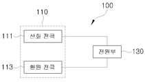
도 1을 참조하면, 본 발명의 바람직한 실시예에 따른 축전식 탈염 장치(100)는 전도성 물질로 이루어진 중공사 막 형태의 전극을 이용하여 축전식 탈염 장치(100)로 유입된 물의 탈 이온화를 수행한다. 이를 위해, 축전식 탈염 장치(100)는 전극(110) 및 전원부(130)를 포함한다.Referring to FIG. 1, a
전원부(130)는 전극(110)에 전압을 인가한다. 여기서, 전원부(130)는 물의 전기 분해가 일어나지 않는 전압 범위에 속하는 전압을 전극(110)에 인가할 수 있다. 예컨대, 전원부(130)는 2V 이하의 전압을 전극(110)에 인가할 수 있다. 이에 따라, 전극(110)에는 일정한 전하량이 하전되고, 축전식 탈염 장치(100)는 축전식 탈염 장치(100)로 공급되는 염수를 탈염하게 된다.The
전극(110)은 산화 전극(111)과 환원 전극(113)을 포함한다. 여기서, 산화 전극(111) 및 환원 전극(113) 중 적어도 하나의 전극은 전도성 물질로 이루어진 중공사 막 형태의 전극이다. 전도성 물질은 높은 비표면적으로 인해 우수한 비축전용량 및 탁월한 전기 전도성을 가지는 탄소 동소체 등일 수 있다.The
즉, 중공사 막 형태의 전극은 탄소 동소체 등과 같이 다공성 전도성 물질로 이루어지고 내부가 비어있는 관 형태로 이루어진다. 이로 인해, 본 발명에 따른 축전식 탈염 장치(100)는 기존의 탄소 동소체가 나타내는 우수한 비표면적 및 전기 전도성을 유지하면서 내공관의 형상으로 인해 획득되는 이점을 탈염 공정에 활용할 수 있다. 예컨대, 중공사 막 형태의 전극은 외경(바깥 직경)이 500 ~ 5,000μm이고, 벽 두께가 50 ~ 1,000μm일 수 있다.That is, the electrode in the form of a hollow fiber is made of a porous conductive material such as carbon or the like and has an inner hollow shape. Accordingly, the storage and
이때, 중공사 막 형태의 전극은 집전체의 법선 방향으로 집전체와 연결될 수 있다. 여기서, 집전체는 전원부(130)로부터 인가되는 전압을 중공사 막 형태의 전극에 인가하는 부재를 말한다. 예컨대, 중공사 막 형태의 전극은 집전체의 평면 상에 수직 방향이나 집전체의 평면과 각을 이루도록 집전체와 연결될 수 있다.At this time, the electrode in the form of a hollow fiber membrane can be connected to the current collector in the normal direction of the current collector. Here, the current collector refers to a member that applies a voltage applied from the
이와 같이, 중공사 막 형태의 전극이 집전체에 법선 방향으로 연결되어, 본 발명에 따른 축전식 탈염 장치(100)는 단위 면적당 높은 충전율로 인해 탄소 동소체가 가지는 이점을 극대화할 수 있다. 또한, 단위 부피당 막 표면적이 높기 때문에 높은 탈염 용량 및 효율을 획득할 수 있다. 아울러, 중공사 막 형태의 전극이 집전체에 법선 방향으로 연결됨으로써, 추가적인 분리체의 사용을 줄일 수 있고, 운영 시 시스템의 조건에 따라 전극의 길이를 유연하게 조절할 수 있는 이점이 있다.In this way, the hollow fiber membrane electrode is connected to the current collector in the normal direction, and the storage and
그리고, 중공사 막 형태의 전극은 직육면체 등과 같은 다면체의 형상으로 이루어질 수 있다. 물론, 중공사 막 형태의 전극은 원기둥, 원뿔 등과 같은 회전체의 형상으로 이루어질 수도 있다.The hollow fiber membrane electrode may have a polyhedral shape such as a rectangular parallelepiped. Of course, the hollow-film-like electrode may have a shape of a rotating body such as a cylinder, a cone, or the like.
또한, 중공사 막 형태의 전극은 유기 물질이나 나노 입자가 도핑될 수 있다.In addition, the hollow-film-like electrode can be doped with an organic material or nanoparticles.
즉, 중공사 막 형태의 전극은 폴리설폰, 폴리아크릴로니트릴(PAN), 폴리카보네이트, 폴리이미드, 폴리비닐부티랄(PVB), 아민 화합물 및 아실할라이드 화합물 중 적어도 하나의 물질과 탄소 동소체 등과 같은 전도성 물질이 혼합되어 중공사 막 형태로 이루어질 수 있다. 여기서, 아민 화합물은 m-페닐렌디아민(MPD), p-페닐렌디아민, 1,3,6-벤젠트리아민, 4-클로로-1,3-페닐렌디아민, 6-클로로-1,3-페닐렌디아민, 3-클로로-1,4-페닐렌 디아민 및 이들의 혼합물로 이루어진 군을 말한다. 그리고, 아실할라이드 화합물은 트리메조일클로라이드(TMC), 이소프탈로일클로라이드, 테레프탈로일클로라이드로 이루어진 군을 말한다. 이로 인해, 중공사 막 형태의 전극 제조시 분산성을 높일 수 있다.That is, the electrode in the form of a hollow fiber membrane may be formed of at least one material selected from the group consisting of polysulfone, polyacrylonitrile (PAN), polycarbonate, polyimide, polyvinyl butyral (PVB), an amine compound and an acyl halide compound, The conductive material may be mixed to form a hollow fiber membrane. Here, the amine compound may be at least one selected from the group consisting of m-phenylenediamine (MPD), p-phenylenediamine, 1,3,6-benzenetriamine, 4-chloro- Phenylenediamine, 3-chloro-1,4-phenylenediamine, and mixtures thereof. And, the acyl halide compound refers to a group consisting of trimesoyl chloride (TMC), isophthaloyl chloride, and terephthaloyl chloride. This makes it possible to increase the dispersibility in the production of the electrode in the form of a hollow fiber membrane.
또한, 탄소 동소체 등과 같은 전도성 물질로 이루어진 중공사 막 형태의 전극은 외부 표면이나 내부 표면에 산화-환원 활성을 가지는 금속 나노 입자가 도핑될 수 있다. 여기서, 금속 나노 입자는 이산화 타이타늄(TiO2), 이산화 규소(SiO2), 이산화 망간(MnO2) 등일 수 있다. 이로 인해, 중공사 막 형태의 전극의 비정전용량을 증대시킬 수 있다.In addition, a hollow fiber membrane electrode made of a conductive material such as a carbon isotope can be doped with metal nanoparticles having an oxidation-reduction activity on an outer surface or an inner surface. Here, the metal nanoparticles may be titanium dioxide (TiO2 ), silicon dioxide (SiO2 ), manganese dioxide (MnO2 ), or the like. This makes it possible to increase the non-discharge capacity of the electrode in the form of a hollow fiber membrane.
아울러, 탄소 동소체 등과 같은 전도성 물질로 이루어진 중공사 막 형태의 전극은 유기 물질을 통해 외부 표면이나 내부 표면을 화학적으로 개질하여 이루어질 수 있다. 여기서, 유기 물질은 카르복실기, 히드록실기, 술폰산기, 포스포닉기 및 카르보닐기 등의 작용기를 가진 물질을 말한다. 이로 인해, 중공사 막 형태의 전극의 물리화학적 성질 및 전도성을 향상시킬 수 있다.In addition, a hollow fiber membrane electrode made of a conductive material such as a carbon isotope may be formed by chemically modifying an outer surface or an inner surface through an organic material. Here, the organic material refers to a substance having a functional group such as a carboxyl group, a hydroxyl group, a sulfonic acid group, a phosphonic group and a carbonyl group. As a result, the physico-chemical properties and conductivity of the electrode in the form of a hollow fiber membrane can be improved.
한편, 축전식 탈염 장치(100)는 염수가 공급되는 유로는 열어 놓고 탈염된 물이 유출되는 유로는 미리 설정된 시간 동안 차단할 수 있다. 여기서, 미리 설정된 시간은 축전식 탈염 장치(100)의 탈염 가능 용량, 염수의 공급 속도 등을 기반으로 설정될 수 있다. 그리고, 미리 설정된 시간이 지나면, 축전식 탈염 장치(100)는 탈염된 물이 축전식 탈염 장치(100)의 외부로 유출되도록 탈염된 물이 유출되는 유로를 열 수 있다. 이와 같이, 탈염된 물이 유출되는 유로를 잠시 막아줌으로써, 축전식 탈염 장치(100) 내부에 물이 체류하는 시간을 늘려 탈염 효율을 증대시킬 수 있다.On the other hand, in the storage and
이때, 축전식 탈염 장치(100)는 미리 설정된 주기에 따라 탈염된 물이 유출되는 유로를 차단할 수 있다. 여기서, 미리 설정된 주기는 축전식 탈염 장치(100)의 탈염 가능 용량, 염수의 공급 속도, 유출 유로의 차단 시간 등을 기반으로 설정될 수 있다.At this time, the storage and
그러면, 도 2 및 도 3을 참조하여 본 발명의 바람직한 실시예에 따른 축전식 탈염 장치의 일례에 대하여 설명한다.2 and 3, an explanation will be given of an example of a storage and desalination apparatus according to a preferred embodiment of the present invention.
도 2는 도 1에 도시한 축전식 탈염 장치의 일례를 설명하기 위한 사시도이고, 도 3은 도 2에 도시한 축전식 탈염 장치의 단면도이다.FIG. 2 is a perspective view for explaining an example of the storage and desalination apparatus shown in FIG. 1, and FIG. 3 is a sectional view of the storage and desalination apparatus shown in FIG.
도 2 및 도 3을 참조하면, 축전식 탈염 장치(100)는 산화 전극(111), 환원 전극(113), 하우징(150), 제1 집전체(171), 제2 집전체(173), 제1 연결 부재(191) 및 제2 연결 부재(193)를 포함할 수 있다. 그리고, 도 2 및 도 3에는 도시하지 않았으나, 전원부(130)는 제1 집전체(171)와 제2 집전체(173)에 연결되어 있다.2 and 3, the
복수의 산화 전극(111)은 제1 집전체(171)의 수직 방향으로 제1 집전체(171)와 연결된다. 각각의 산화 전극(111)은 제1 집전체(171)에 형성된 구멍에 삽입된 제1 연결 부재(191)를 통해 제1 집전체(171)와 연결된다. 제1 연결 부재(191)는 내부가 비어있는 관 형태로 이루어진다. 물론, 각각의 산화 전극(111)은 제1 집전체(171)에 형성된 구멍에 직접 삽입되어 제1 집전체(171)와 연결될 수도 있다.The plurality of
복수의 환원 전극(113)은 제2 집전체(173)의 수직 방향으로 제2 집전체(173)와 연결된다. 각각의 환원 전극(113)은 제2 집전체(173)에 형성된 구멍에 삽입된 제2 연결 부재(193)를 통해 제2 집전체(173)와 연결된다. 제2 연결 부재(193)는 내부가 비어있는 관 형태로 이루어진다. 물론, 각각의 환원 전극(113)은 제2 집전체(173)에 형성된 구멍에 직접 삽입되어 제2 집전체(173)와 연결될 수도 있다.The plurality of
이때, 복수의 산화 전극(111)과 복수의 환원 전극(113)은 서로 접촉하지 않도록 지그재그 형상으로 배치되어 있다. 이로 인해, 제한된 공간 안에서 비표면적을 극대화할 수 있다. 한편, 복수의 산화 전극(111)과 복수의 환원 전극(113)이 내부에 관이 형성된 원기둥 형상으로 이루어진 것으로 도 2 및 도 3에 도시하였으나, 이에 한정되지 않고 실시예에 따른 전극(111, 113)의 형상은 직육면체 등과 같은 다면체나 원뿔 등과 같은 회전체의 형상으로 이루어질 수도 있다.At this time, the plurality of
하우징(150)은 축전식 탈염 장치(100)의 구성요소를 보호하고, 염수의 공급, 염수의 탈염, 탈염된 물의 유출을 위한 공간들(SP1, SP2, SP3)을 형성한다. 한편, 하우징(150)이 일체의 형태로 이루어진 것으로 도 2 및 도 3에 도시하였으나, 이에 한정되지 않고 실시예에 따라 하우징(150)은 복수개의 모듈로 구성될 수 있다.The
복수의 산화 전극(111)과 복수의 환원 전극(113)이 배치된 공간, 즉 제1 집전체(171)와 제2 집전체(173) 사이에 형성된 제1 공간(SP1)은 축전식 탈염 장치(100)의 내부로 공급된 염수가 탈염되는 공간이다. 이때, 제1 공간(SP1)의 일측면에 제3 홀(WH3)이 형성되고, 다른 측면에 제4 홀(WH4)이 형성될 수 있다. 염수는 제3 홀(WH3)이나 제4 홀(WH4)을 통해 제1 공간(SP1)으로 공급될 수 있다. 또한, 탈염된 물은 제3 홀(WH3)이나 제4 홀(WH4)을 통해 외부로 유출될 수 있다. 즉, 제3 홀(WH3)과 제4 홀(WH4)은 염수의 공급 유로의 역할을 수행하거나 탈염된 물의 유출 유로의 역할을 수행할 수 있다.The space in which the plurality of
복수의 산화 전극(111)이 연결된 제1 집전체(171)의 상부에 위치한 제2 공간(SP2)은 축전식 탈염 장치(100)로 공급되는 염수를 제1 공간(SP1)으로 전달하거나, 제1 공간(SP1)에서 탈염된 물이 전달되는 공간이다. 이때, 제2 공간(SP2)의 일측면에 제1 홀(WH1)이 형성될 수 있다. 염수는 제1 홀(WH1)을 통해 제2 공간(SP2)으로 공급될 수 있다. 또한, 탈염된 물은 제1 홀(WH1)을 통해 외부로 유출될 수 있다. 즉, 제1 홀(WH1)은 염수의 공급 유로의 역할을 수행하거나 탈염된 물의 유출 유로의 역할을 수행할 수 있다.The second space SP2 located above the first
복수의 환원 전극(113)이 연결된 제2 집전체(173)의 하부에 위치한 제3 공간(SP3)은 축전식 탈염 장치(100)로 공급되는 염수를 제1 공간(SP1)으로 전달하거나, 제1 공간(SP1)에서 탈염된 물이 전달되는 공간이다. 이때, 제3 공간(SP3)의 일측면에 제2 홀(WH2)이 형성될 수 있다. 염수는 제2 홀(WH2)을 통해 제3 공간(SP3)으로 공급될 수 있다. 또한, 탈염된 물은 제2 홀(WH2)을 통해 외부로 유출될 수 있다. 즉, 제2 홀(WH2)은 염수의 공급 유로의 역할을 수행하거나 탈염된 물의 유출 유로의 역할을 수행할 수 있다.The third space SP3 located below the second
이와 같이, 지그재그 형상으로 배치된 산화 전극(111)과 환원 전극(113)이 전도성 물질로 이루어진 중공사 막 형태의 전극으로 이루어져 있어, 높은 충진 밀도를 획득할 수 있고, 염수가 전극과 접촉되는 빈도가 높아져 탈염 용량 및 효율을 증대시킬 수 있다. 아울러, 염수에 존재하는 전기적 중성을 띠는 입자들도 여과 작용으로 인해 제거되는 효과도 가질 수 있다. 또한, 중공사 막 형태의 전극의 내공관으로 인해 축전식 탈염 장치(100) 내에 염수가 체류하는 시간을 늘려 탈염 효율을 증대시킬 수 있다.Since the
한편, 축전식 탈염 장치(100)가 염수의 공급 유로나 탈염된 물의 유출 유로의 역할을 수행하는 홀을 4개(WH1, WH2, WH3, WH4) 구비하는 것으로 도 2 및 도 3에 도시하였으나, 이에 한정되지 않고 실시예에 따라 축전식 탈염 장치(100)는 2개의 홀(염수의 공급 유로의 역할을 수행하는 홀과 탈염된 물의 유출 유로의 역할을 수행하는 홀)을 구비할 수도 있다.2 and 3, the
또한, 복수의 산화 전극(111)과 복수의 환원 전극(113)이 1차원 배열 형태로 배치된 것으로 도 2 및 도 3에 도시하였으나, 이에 한정되지 않고 실시예에 따라 복수의 산화 전극(111)과 복수의 환원 전극(113)은 2차원 배열 형태로 배치될 수도 있다.2 and 3, a plurality of
그러면, 도 4 및 도 5를 참조하여 본 발명의 바람직한 실시예에 따른 축전식 탈염 장치의 다른 예에 대하여 설명한다.4 and 5, another example of the de-ionization apparatus according to the preferred embodiment of the present invention will be described.
도 4는 도 1에 도시한 축전식 탈염 장치의 다른 예에 따른 전극을 설명하기 위한 도면이다.FIG. 4 is a view for explaining an electrode according to another example of the electrothermal desalination apparatus shown in FIG. 1. FIG.
도 4를 참조하면, 복수의 산화 전극(111)은 제1 집전체(171)의 법선 방향으로 제1 집전체(171)와 연결될 수 있다. 즉, 산화 전극(111)은 제1 집전체(171)의 평면과 각을 이루도록 제1 집전체(171)와 연결될 수 있다.Referring to FIG. 4, the plurality of
복수의 환원 전극(113)은 제2 집전체(173)의 법선 방향으로 제2 집전체(173)와 연결될 수 있다. 즉, 환원 전극(113)은 제2 집전체(173)의 평면과 각을 이루도록 제2 집전체(173)와 연결될 수 있다.The plurality of
이때, 복수의 산화 전극(111)과 복수의 환원 전극(113)은 서로 접촉하지 않도록 지그재그 형상으로 배치되어 있다.At this time, the plurality of
도 5는 도 1에 도시한 축전식 탈염 장치의 또 다른 예에 따른 전극을 설명하기 위한 도면이다.5 is a view for explaining an electrode according to still another example of the electrothermal desalination apparatus shown in FIG.
도 5를 참조하면, 복수의 산화 전극(111)과 복수의 환원 전극(113) 전부는 제1 집전체(171)와 연결될 수 있다. 이때, 복수의 산화 전극(111)과 복수의 환원 전극(171)은 서로 인접하는 전극이 서로 상이하도록 엇갈리게 배치될 수 있다. 예컨대, 산화 전극(111)의 바로 옆에 배치된 전극은 환원 전극(113)이고, 환원 전극(113)의 바로 옆에 배치된 전극은 산화 전극(111)일 수 있다.Referring to FIG. 5, all of the plurality of
이 경우, 제1 집전체(171)는 산화 집전 모듈(도시하지 않음) 및 환원 집전 모듈(도시하지 않음)을 구비할 수 있다. 산화 집전 모듈에는 복수의 산화 전극(111)이 연결되고, 환원 집전 모듈에는 복수의 환원 전극(113)이 연결될 수 있다. 그리고, 전원부(130)는 산화 집전 모듈과 환원 집전 모듈에 전압을 인가할 수 있다.In this case, the first
그러면, 도 6 내지 도 8을 참조하여 본 발명의 바람직한 실시예에 따른 축전식 탈염 장치의 물 흐름의 일례에 대하여 설명한다.Hereinafter, an example of the water flow of the thermal decomposition apparatus according to the preferred embodiment of the present invention will be described with reference to FIGS. 6 to 8. FIG.
도 6은 본 발명의 바람직한 실시예에 따른 축전식 탈염 장치의 물 흐름의 일례를 설명하기 위한 도면이다.FIG. 6 is a view for explaining an example of the water flow in the thermal desalination apparatus according to the preferred embodiment of the present invention.
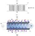
도 6을 참조하면, 염수가 산화 전극(111)과 환원 전극(113)이 배치된 공간으로 직접 유입되고, 탈염된 물이 산화 전극(111)과 환원 전극(113)이 배치된 공간으로부터 직접 유출될 수 있다. 이와 같이, 산화 전극(111)과 환원 전극(113)이 집전체(171, 173)의 법선 방향으로 배치되어 있어, 높은 충진 밀도를 획득할 수 있을 뿐만 아니라 산화 전극(111)과 환원 전극(113)이 지그재그 형태로 배치되어 있어 염수가 이동하면서 전극(111, 113)과 접촉하는 빈도를 높여 탈염 용량 및 효율을 증대시킬 수 있다.6, salt water flows directly into the space where the oxidizing
도 7은 본 발명의 바람직한 실시예에 따른 축전식 탈염 장치의 물 흐름의 다른 예를 설명하기 위한 도면이다.FIG. 7 is a view for explaining another example of the water flow of the thermal desalination apparatus according to the preferred embodiment of the present invention.
도 7을 참조하면, 염수가 산화 전극(111)과 환원 전극(113)이 배치된 공간으로 직접 유입되고, 탈염된 물이 산화 전극(111)이나 환원 전극(113)의 내공관을 통해 유출될 수 있다. 이와 같이, 중공사 막 형태의 전극의 내공관을 통해 물이 흐르도록 유로를 형성함으로써, 전극(111, 113)에 접촉하는 시간을 늘려 탈염 효율을 증대시킬 수 있다.7, salt water is directly introduced into the space where the oxidizing
도 8은 본 발명의 바람직한 실시예에 따른 축전식 탈염 장치의 물 흐름의 또 다른 예를 설명하기 위한 도면이다.8 is a view for explaining another example of the water flow of the thermal desalination apparatus according to the preferred embodiment of the present invention.
도 8을 참조하면, 염수가 산화 전극(111)이나 환원 전극(113)의 내공관을 통해 산화 전극(111)과 환원 전극(113)이 배치된 공간으로 유입되고, 탈염된 물이 산화 전극(111)과 환원 전극(113)이 배치된 공간으로부터 직접 유출될 수 있다. 이와 같이, 중공사 막 형태의 전극의 내공관을 통해 염수를 공급함으로써, 전극 내부 전체를 통해 물이 이동되기 때문에 탈염 용량을 증대시킬 수 있고, 물의 이동이 기존 확산 방식에서 흐름 저항이 현저히 낮은 난류 형성에 의해 이루어지기 때문에 빠른 시간 내에 균일한 탈염수를 획득할 수 있다.8, salt water flows into the space where the oxidizing
한편, 염수가 산화 전극(111)의 내공관을 통해 산화 전극(111)과 환원 전극(113)이 배치된 공간으로 유입되고, 탈염된 물이 환원 전극(113)의 내공관을 통해 유출될 수도 있다. 물론, 이 반대 경로도 가능하다.On the other hand, the brine may flow into the space where the oxidizing
그러면, 도 9를 참조하여 본 발명의 바람직할 실시예에 따른 축전식 탈염 장치의 운영 방법에 대하여 설명한다.A method of operating the storage desalination apparatus according to a preferred embodiment of the present invention will now be described with reference to FIG.
도 9는 본 발명의 바람직한 실시예에 따른 축전식 탈염 장치의 운영 방법을 설명하기 위한 흐름도이다.FIG. 9 is a flowchart for explaining a method of operating a storage and desalination apparatus according to a preferred embodiment of the present invention.
도 9를 참조하면, 염수가 축전식 탈염 장치(100)로 공급된다(S210). 여기서, 축전식 탈염 장치(100)는 산화 전극(111)과 환원 전극(113)을 포함하며, 산화 전극(111) 및 환원 전극(113) 중 적어도 하나의 전극은 전도성 물질로 이루어진 중공사 막 형태의 전극이다. 이때, 중공사 막 형태의 전극은 집전체의 법선 방향으로 집전체와 연결될 수 있다. 그리고, 중공사 막 형태의 전극은 다면체나 회전체의 형상으로 이루어질 수 있다. 또한, 중공사 막 형태의 전극은 유기 물질이나 나노 입자가 도핑될 수 있다.Referring to FIG. 9, salt water is supplied to the electrothermal desalination apparatus 100 (S210). At least one of the oxidizing
그러면, 축전식 탈염 장치(100)는 공급된 염수를 중공사 막 형태의 전도성 물질로 이루어진 전극을 통해 탈염한다(S230). 이때, 염수는 중공사 막 형태의 전극의 내공관을 통해 축전식 탈염 장치(100)로 공급될 수 있다.Then, the
그런 다음, 축전식 탈염 장치(100)는 탈염된 물을 축전식 탈염 장치(100)의 외부로 유출한다(S250). 이때, 탈염된 물은 중공사 막 형태의 전극의 내공관을 통해 축전식 탈염 장치(100)의 외부로 유출될 수 있다.Then, the storage and
한편, 축전식 탈염 장치(100)는 염수가 공급되는 유로는 열어 놓고 탈염된 물이 유출되는 유로는 미리 설정된 시간 동안 차단할 수 있다. 그리고, 미리 설정된 시간이 지나면, 축전식 탈염 장치(100)는 탈염된 물이 축전식 탈염 장치(100)의 외부로 유출되도록 탈염된 물이 유출되는 유로를 열 수 있다.On the other hand, in the storage and
이때, 축전식 탈염 장치(100)는 미리 설정된 주기에 따라 탈염된 물이 유출되는 유로를 차단할 수 있다.At this time, the storage and
즉, 축전식 탈염 장치(100)의 운영 방법은 염수의 공급 경로와 탈염된 물의 유출 경로를 토대로 아래와 같이 4개의 운영 방법으로 구분할 수 있다.That is, the operation method of the storage and
첫 번째 운영 방법은 염수가 산화 전극(111)과 환원 전극(113)이 배치된 공간으로 직접 유입되고, 탈염된 물이 산화 전극(111)과 환원 전극(113)이 배치된 공간으로부터 직접 유출되는 운영 방법이다.In the first operating method, salt water directly flows into the space where the oxidizing
두 번째 운영 방법은 염수가 산화 전극(111)과 환원 전극(113)이 배치된 공간으로 직접 유입되고, 탈염된 물이 산화 전극(111)이나 환원 전극(113)의 내공관을 통해 유출되는 운영 방법이다.The second operating method is that the saline solution flows directly into the space where the oxidizing
세 번째 운영 방법은 염수가 산화 전극(111)이나 환원 전극(113)의 내공관을 통해 산화 전극(111)과 환원 전극(113)이 배치된 공간으로 유입되고, 탈염된 물이 산화 전극(111)과 환원 전극(113)이 배치된 공간으로부터 직접 유출되는 운영 방법이다.In the third operating method, salt water flows into the space where the oxidizing
네 번째 운영 방법은 염수가 산화 전극(111)의 내공관을 통해 산화 전극(111)과 환원 전극(113)이 배치된 공간으로 유입되고, 탈염된 물이 환원 전극(113)의 내공관을 통해 유출되는 운영 방법이다. 물론, 이 반대 경로도 가능하다.In the fourth operating method, salt water flows into the space where the oxidizing
본 발명은 또한 컴퓨터로 읽을 수 있는 기록 매체에 컴퓨터가 읽을 수 있는 코드로서 구현하는 것이 가능하다. 컴퓨터로 읽을 수 있는 기록 매체는 컴퓨터에 의하여 읽혀질 수 있는 데이터가 저장되는 모든 종류의 기록 장치를 포함한다. 컴퓨터가 읽을 수 있는 기록 매체의 예로는 롬(ROM), 램(RAM), 씨디-롬(CD-ROM), 자기 테이프, 플로피 디스크, 광 데이터 저장장치 등이 있으며, 또한 캐리어 웨이브(인터넷을 통한 전송)의 형태로 구현되는 것도 포함한다. 또한, 컴퓨터가 읽을 수 있는 기록 매체는 유무선 통신망으로 연결된 컴퓨터 장치에 분산되어 분산 방식으로 컴퓨터가 읽을 수 있는 코드가 저장되고 실행될 수 있다.The present invention can also be embodied as computer-readable codes on a computer-readable recording medium. A computer-readable recording medium includes all kinds of recording apparatuses in which data that can be read by a computer is stored. Examples of the computer-readable recording medium include a ROM, a RAM, a CD-ROM, a magnetic tape, a floppy disk, an optical data storage device, and a carrier wave Transmission). In addition, the computer-readable recording medium may be distributed to computer devices connected to a wired / wireless communication network, and a computer-readable code may be stored and executed in a distributed manner.
이상에서 본 발명의 바람직한 실시예에 대하여 상세하게 설명하였지만 본 발명은 상술한 특정의 바람직한 실시예에 한정되지 아니하며, 다음의 청구범위에서 청구하는 본 발명의 요지를 벗어남이 없이 당해 발명이 속하는 기술분야에서 통상의 지식을 가진 자라면 누구든지 다양한 변형 실시가 가능한 것은 물론이고, 그와 같은 변경은 청구범위 기재의 범위 내에 있게 된다.While the present invention has been particularly shown and described with reference to exemplary embodiments thereof, it is to be understood that the invention is not limited to the disclosed exemplary embodiments, but, on the contrary, It will be understood by those skilled in the art that various changes may be made and equivalents may be substituted without departing from the scope of the appended claims.
100 : 축전식 탈염 장치,110 : 전극,
111 : 산화 전극,113 : 환원 전극,
130 : 전원부,150 : 하우징,
171 : 제1 집전체,173 : 제2 집전체,
191 : 제1 연결 부재,193 : 제2 연결 부재100: a capacitive desalination device, 110: an electrode,
111: oxidation electrode, 113: reduction electrode,
130: power supply unit, 150: housing,
171: the first collection, 173: the second collection,
191: first connecting member, 193: second connecting member
Claims (10)
Translated fromKorean상기 전극에 전압을 인가하는 전원부; 및
상기 전원부로부터 인가된 전압을 상기 전극에 인가하는 집전체;
를 포함하며,
상기 산화 전극 및 상기 환원 전극 중 적어도 하나의 전극은 전도성 물질로 이루어진 중공사 막 형태의 전극이고,
상기 중공사 막 형태의 전극은, 상기 집전체의 법선 방향으로 상기 집전체와 연결되며,
상기 복수의 산화 전극과 상기 복수의 환원 전극은 서로 접촉하지 않도록 지그재그 형상으로 배치되는 축전식 탈염 장치.An electrode including a plurality of oxidation electrodes and a plurality of reduction electrodes;
A power supply unit for applying a voltage to the electrode; And
A current collector for applying a voltage applied from the power supply unit to the electrode;
/ RTI >
Wherein at least one of the oxidation electrode and the reduction electrode is a hollow fiber membrane electrode made of a conductive material,
Wherein the hollow fiber membrane electrode is connected to the current collector in a direction normal to the current collector,
Wherein the plurality of oxidation electrodes and the plurality of reduction electrodes are arranged in a zigzag shape so as not to contact each other.
상기 중공사 막 형태의 전극은, 다면체 또는 회전체의 형상으로 이루어진 축전식 탈염 장치.The method of claim 1,
Wherein the electrode in the form of a hollow fiber membrane has a shape of a polyhedron or a rotating body.
상기 중공사 막 형태의 전극은, 유기 물질이나 나노 입자가 도핑된 축전식 탈염 장치.The method of claim 1,
The hollow-film-type electrode is an electrodeposited desalination apparatus doped with an organic substance or nanoparticles.
상기 전도성 물질은, 탄소 동소체인 축전식 탈염 장치.The method of claim 1,
Wherein the conductive material is a carbon isotope.
염수가 상기 축전식 탈염 장치로 공급되는 단계;
상기 축전식 탈염 장치로 공급된 상기 염수가 상기 중공사 막 형태의 전극을 통해 탈염되는 단계; 및
상기 중공사 막 형태의 전극을 통해 탈염된 물이 상기 축전식 탈염 장치의 외부로 유출되는 단계;
를 포함하는 축전식 탈염 장치의 운영 방법.An electrode including a plurality of oxidation electrodes and a plurality of reduction electrodes, and a current collector for applying a voltage applied from the power source to the electrode, wherein at least one of the oxidation electrode and the reduction electrode is hollow Wherein the hollow fiber membrane electrode is connected to the current collector in the normal direction of the current collector and the plurality of oxidation electrodes and the plurality of reduction electrodes are disposed in a zigzag shape so as not to contact each other A method for operating a storage desalination apparatus,
Salt water is supplied to the above-described electrothermal desalination apparatus;
Desalting the brine supplied to the storage and desalination apparatus through the hollow fiber membrane electrode; And
Discharging the desalted water through the electrode in the form of a hollow fiber membrane to the outside of the electrothermal desalination apparatus;
Wherein said method comprises the steps of:
염수 공급 단계는, 상기 중공사 막 형태의 전극의 내공관을 통해 상기 염수가 상기 축전식 탈염 장치로 공급되는 것으로 이루어진 축전식 탈염 장치의 운영 방법.The method of claim 6,
Wherein the brine supplying step comprises supplying the brine through the inner hollow tube of the hollow fiber membrane electrode to the electrolytic desalinator.
상기 탈염된 물의 유출 단계는, 상기 중공사 막 형태의 전극의 내공관을 통해 상기 탈염된 물이 상기 축전식 탈염 장치의 외부로 유출되는 것으로 이루어진 축전식 탈염 장치의 운영 방법.The method of claim 6,
Wherein the step of draining the desalted water comprises flowing the desalted water out of the condensate desalination apparatus through an inner tube of the hollow fiber membrane electrode.
상기 탈염된 물의 유출 단계는, 미리 설정된 시간 동안 물의 유출을 차단하고, 상기 미리 설정된 시간이 지나면 상기 탈염된 물이 상기 축전식 탈염 장치의 외부로 유출되는 것으로 이루어진 축전식 탈염 장치의 운영 방법.The method of claim 6,
Wherein the step of draining the desalted water comprises blocking the outflow of water for a predetermined time and discharging the desalted water to the outside of the storage desalination device after the predetermined time has elapsed.
Priority Applications (1)
| Application Number | Priority Date | Filing Date | Title |
|---|---|---|---|
| KR1020160113757AKR101818621B1 (en) | 2016-09-05 | 2016-09-05 | Capacitive deionization device and method for operating thereof |
Applications Claiming Priority (1)
| Application Number | Priority Date | Filing Date | Title |
|---|---|---|---|
| KR1020160113757AKR101818621B1 (en) | 2016-09-05 | 2016-09-05 | Capacitive deionization device and method for operating thereof |
Publications (1)
| Publication Number | Publication Date |
|---|---|
| KR101818621B1true KR101818621B1 (en) | 2018-02-21 |
Family
ID=61524362
Family Applications (1)
| Application Number | Title | Priority Date | Filing Date |
|---|---|---|---|
| KR1020160113757AExpired - Fee RelatedKR101818621B1 (en) | 2016-09-05 | 2016-09-05 | Capacitive deionization device and method for operating thereof |
Country Status (1)
| Country | Link |
|---|---|
| KR (1) | KR101818621B1 (en) |
Cited By (2)
| Publication number | Priority date | Publication date | Assignee | Title |
|---|---|---|---|---|
| KR20190090651A (en)* | 2018-01-25 | 2019-08-02 | 엘지전자 주식회사 | filter for water treatment apparatus and water treatment apparatus having thereof |
| WO2021033918A1 (en)* | 2019-08-19 | 2021-02-25 | 엘지전자 주식회사 | Filter for water treatment device |
- 2016
- 2016-09-05KRKR1020160113757Apatent/KR101818621B1/ennot_activeExpired - Fee Related
Cited By (3)
| Publication number | Priority date | Publication date | Assignee | Title |
|---|---|---|---|---|
| KR20190090651A (en)* | 2018-01-25 | 2019-08-02 | 엘지전자 주식회사 | filter for water treatment apparatus and water treatment apparatus having thereof |
| KR102247227B1 (en)* | 2018-01-25 | 2021-05-03 | 엘지전자 주식회사 | filter for water treatment apparatus and water treatment apparatus having thereof |
| WO2021033918A1 (en)* | 2019-08-19 | 2021-02-25 | 엘지전자 주식회사 | Filter for water treatment device |
Similar Documents
| Publication | Publication Date | Title |
|---|---|---|
| US6462935B1 (en) | Replaceable flow-through capacitors for removing charged species from liquids | |
| US7974076B2 (en) | Desalination device and associated method | |
| US20080185294A1 (en) | Liquid management method and system | |
| US20200131058A1 (en) | Voltage-controlled anion exchange membrane enabling selective ion affinities for water desalination and device containing the same | |
| US12030795B2 (en) | Desalination device and method of manufacturing such a device | |
| EP2109587A1 (en) | Desalination method and device comprising supercapacitor electrodes | |
| EP3708544B1 (en) | Hybrid power generation apparatus capable of electricity production and deionization simultaneously | |
| US20120273359A1 (en) | Flow-through electrode capacitive desalination | |
| KR20150008348A (en) | Hybrid seawater desalination systems | |
| US20050036270A1 (en) | Fluid deionization flow through capacitor systems | |
| KR20220012643A (en) | Manufacturing Method of Slurry Carbon Electrode for Flow Electrode-based Capacitive desalination | |
| KR101818621B1 (en) | Capacitive deionization device and method for operating thereof | |
| US10522849B2 (en) | Electrochemical cell comprising channel-type flowable electrode units | |
| KR101750417B1 (en) | Lattice type flow cell structure | |
| KR100442773B1 (en) | Desalination System and Regeneration Method by Electrosorption | |
| KR20170034953A (en) | CDI Module and method for preparing the same | |
| US10556812B2 (en) | System and method for reducing the dissolved solids of a non-potable aqueous flow | |
| KR20140119545A (en) | Capacitive deionization apparatus and deionization system | |
| KR100979028B1 (en) | Separation membrane for deionization of wastewater or brine and method of ion removal of wastewater or brine using same | |
| KR20160136266A (en) | Lattice type flow cell structure | |
| KR101137042B1 (en) | Capacitive deionization device, Method for capacitively deionizing, and Desalination apparatus, Wastewater treatment apparatus using the same | |
| Dehghan et al. | Investigation of effective parameters on brackish water desalination by flow-electrode capacitive deionization | |
| EP1291323B1 (en) | Replaceable flow-through capacitors for removing charged species from liquids | |
| US20230249134A1 (en) | System and Method for Reducing the Dissolved Solids of a Non-Potable Aqueous Flow | |
| KR102300797B1 (en) | Capacitive deionization electrode module of roll type, and water treatment apparatus using the same |
Legal Events
| Date | Code | Title | Description |
|---|---|---|---|
| PA0109 | Patent application | St.27 status event code:A-0-1-A10-A12-nap-PA0109 | |
| PA0201 | Request for examination | St.27 status event code:A-1-2-D10-D11-exm-PA0201 | |
| P11-X000 | Amendment of application requested | St.27 status event code:A-2-2-P10-P11-nap-X000 | |
| P13-X000 | Application amended | St.27 status event code:A-2-2-P10-P13-nap-X000 | |
| D13-X000 | Search requested | St.27 status event code:A-1-2-D10-D13-srh-X000 | |
| D14-X000 | Search report completed | St.27 status event code:A-1-2-D10-D14-srh-X000 | |
| PE0902 | Notice of grounds for rejection | St.27 status event code:A-1-2-D10-D21-exm-PE0902 | |
| E13-X000 | Pre-grant limitation requested | St.27 status event code:A-2-3-E10-E13-lim-X000 | |
| P11-X000 | Amendment of application requested | St.27 status event code:A-2-2-P10-P11-nap-X000 | |
| P13-X000 | Application amended | St.27 status event code:A-2-2-P10-P13-nap-X000 | |
| PE0701 | Decision of registration | St.27 status event code:A-1-2-D10-D22-exm-PE0701 | |
| GRNT | Written decision to grant | ||
| PR0701 | Registration of establishment | St.27 status event code:A-2-4-F10-F11-exm-PR0701 | |
| PR1002 | Payment of registration fee | St.27 status event code:A-2-2-U10-U11-oth-PR1002 Fee payment year number:1 | |
| PG1601 | Publication of registration | St.27 status event code:A-4-4-Q10-Q13-nap-PG1601 | |
| R18-X000 | Changes to party contact information recorded | St.27 status event code:A-5-5-R10-R18-oth-X000 | |
| PN2301 | Change of applicant | St.27 status event code:A-5-5-R10-R13-asn-PN2301 St.27 status event code:A-5-5-R10-R11-asn-PN2301 | |
| R18-X000 | Changes to party contact information recorded | St.27 status event code:A-5-5-R10-R18-oth-X000 | |
| P22-X000 | Classification modified | St.27 status event code:A-4-4-P10-P22-nap-X000 | |
| PR1001 | Payment of annual fee | St.27 status event code:A-4-4-U10-U11-oth-PR1001 Fee payment year number:4 | |
| PC1903 | Unpaid annual fee | St.27 status event code:A-4-4-U10-U13-oth-PC1903 Not in force date:20220110 Payment event data comment text:Termination Category : DEFAULT_OF_REGISTRATION_FEE | |
| K11-X000 | Ip right revival requested | St.27 status event code:A-6-4-K10-K11-oth-X000 | |
| PC1903 | Unpaid annual fee | St.27 status event code:N-4-6-H10-H13-oth-PC1903 Ip right cessation event data comment text:Termination Category : DEFAULT_OF_REGISTRATION_FEE Not in force date:20220110 | |
| PR0401 | Registration of restoration | St.27 status event code:A-6-4-K10-K13-oth-PR0401 | |
| R401 | Registration of restoration | ||
| PR1001 | Payment of annual fee | St.27 status event code:A-4-4-U10-U11-oth-PR1001 Fee payment year number:5 | |
| PR1001 | Payment of annual fee | St.27 status event code:A-4-4-U10-U11-oth-PR1001 Fee payment year number:6 | |
| R18-X000 | Changes to party contact information recorded | St.27 status event code:A-5-5-R10-R18-oth-X000 | |
| R18-X000 | Changes to party contact information recorded | St.27 status event code:A-5-5-R10-R18-oth-X000 | |
| PR1001 | Payment of annual fee | St.27 status event code:A-4-4-U10-U11-oth-PR1001 Fee payment year number:7 |