KR101815972B1 - Apparatus and method for sensing high precision signal using infrared light - Google Patents
Apparatus and method for sensing high precision signal using infrared lightDownload PDFInfo
- Publication number
- KR101815972B1 KR101815972B1KR1020100138939AKR20100138939AKR101815972B1KR 101815972 B1KR101815972 B1KR 101815972B1KR 1020100138939 AKR1020100138939 AKR 1020100138939AKR 20100138939 AKR20100138939 AKR 20100138939AKR 101815972 B1KR101815972 B1KR 101815972B1
- Authority
- KR
- South Korea
- Prior art keywords
- light
- intensity
- receiving
- measured
- light receiving
- Prior art date
- Legal status (The legal status is an assumption and is not a legal conclusion. Google has not performed a legal analysis and makes no representation as to the accuracy of the status listed.)
- Active
Links
Images


Classifications
- G—PHYSICS
- G01—MEASURING; TESTING
- G01B—MEASURING LENGTH, THICKNESS OR SIMILAR LINEAR DIMENSIONS; MEASURING ANGLES; MEASURING AREAS; MEASURING IRREGULARITIES OF SURFACES OR CONTOURS
- G01B11/00—Measuring arrangements characterised by the use of optical techniques
- G01B11/14—Measuring arrangements characterised by the use of optical techniques for measuring distance or clearance between spaced objects or spaced apertures
- G—PHYSICS
- G01—MEASURING; TESTING
- G01S—RADIO DIRECTION-FINDING; RADIO NAVIGATION; DETERMINING DISTANCE OR VELOCITY BY USE OF RADIO WAVES; LOCATING OR PRESENCE-DETECTING BY USE OF THE REFLECTION OR RERADIATION OF RADIO WAVES; ANALOGOUS ARRANGEMENTS USING OTHER WAVES
- G01S3/00—Direction-finders for determining the direction from which infrasonic, sonic, ultrasonic, or electromagnetic waves, or particle emission, not having a directional significance, are being received
- G01S3/78—Direction-finders for determining the direction from which infrasonic, sonic, ultrasonic, or electromagnetic waves, or particle emission, not having a directional significance, are being received using electromagnetic waves other than radio waves
- G01S3/782—Systems for determining direction or deviation from predetermined direction
- G01S3/783—Systems for determining direction or deviation from predetermined direction using amplitude comparison of signals derived from static detectors or detector systems
- G—PHYSICS
- G01—MEASURING; TESTING
- G01J—MEASUREMENT OF INTENSITY, VELOCITY, SPECTRAL CONTENT, POLARISATION, PHASE OR PULSE CHARACTERISTICS OF INFRARED, VISIBLE OR ULTRAVIOLET LIGHT; COLORIMETRY; RADIATION PYROMETRY
- G01J1/00—Photometry, e.g. photographic exposure meter
- G01J1/10—Photometry, e.g. photographic exposure meter by comparison with reference light or electric value provisionally void
- G01J1/20—Photometry, e.g. photographic exposure meter by comparison with reference light or electric value provisionally void intensity of the measured or reference value being varied to equalise their effects at the detectors, e.g. by varying incidence angle
- G01J1/28—Photometry, e.g. photographic exposure meter by comparison with reference light or electric value provisionally void intensity of the measured or reference value being varied to equalise their effects at the detectors, e.g. by varying incidence angle using variation of intensity or distance of source
- G—PHYSICS
- G01—MEASURING; TESTING
- G01J—MEASUREMENT OF INTENSITY, VELOCITY, SPECTRAL CONTENT, POLARISATION, PHASE OR PULSE CHARACTERISTICS OF INFRARED, VISIBLE OR ULTRAVIOLET LIGHT; COLORIMETRY; RADIATION PYROMETRY
- G01J1/00—Photometry, e.g. photographic exposure meter
- G01J1/42—Photometry, e.g. photographic exposure meter using electric radiation detectors
- G01J1/4257—Photometry, e.g. photographic exposure meter using electric radiation detectors applied to monitoring the characteristics of a beam, e.g. laser beam, headlamp beam
- G—PHYSICS
- G01—MEASURING; TESTING
- G01S—RADIO DIRECTION-FINDING; RADIO NAVIGATION; DETERMINING DISTANCE OR VELOCITY BY USE OF RADIO WAVES; LOCATING OR PRESENCE-DETECTING BY USE OF THE REFLECTION OR RERADIATION OF RADIO WAVES; ANALOGOUS ARRANGEMENTS USING OTHER WAVES
- G01S11/00—Systems for determining distance or velocity not using reflection or reradiation
- G01S11/02—Systems for determining distance or velocity not using reflection or reradiation using radio waves
- G01S11/06—Systems for determining distance or velocity not using reflection or reradiation using radio waves using intensity measurements
- G—PHYSICS
- G01—MEASURING; TESTING
- G01S—RADIO DIRECTION-FINDING; RADIO NAVIGATION; DETERMINING DISTANCE OR VELOCITY BY USE OF RADIO WAVES; LOCATING OR PRESENCE-DETECTING BY USE OF THE REFLECTION OR RERADIATION OF RADIO WAVES; ANALOGOUS ARRANGEMENTS USING OTHER WAVES
- G01S5/00—Position-fixing by co-ordinating two or more direction or position line determinations; Position-fixing by co-ordinating two or more distance determinations
- G01S5/16—Position-fixing by co-ordinating two or more direction or position line determinations; Position-fixing by co-ordinating two or more distance determinations using electromagnetic waves other than radio waves
- G—PHYSICS
- G06—COMPUTING OR CALCULATING; COUNTING
- G06F—ELECTRIC DIGITAL DATA PROCESSING
- G06F3/00—Input arrangements for transferring data to be processed into a form capable of being handled by the computer; Output arrangements for transferring data from processing unit to output unit, e.g. interface arrangements
- G06F3/01—Input arrangements or combined input and output arrangements for interaction between user and computer
- G06F3/03—Arrangements for converting the position or the displacement of a member into a coded form
- G06F3/0304—Detection arrangements using opto-electronic means
Landscapes
- Physics & Mathematics (AREA)
- Engineering & Computer Science (AREA)
- General Physics & Mathematics (AREA)
- Radar, Positioning & Navigation (AREA)
- Remote Sensing (AREA)
- Electromagnetism (AREA)
- General Engineering & Computer Science (AREA)
- Theoretical Computer Science (AREA)
- Human Computer Interaction (AREA)
- Spectroscopy & Molecular Physics (AREA)
- Optics & Photonics (AREA)
- Length Measuring Devices By Optical Means (AREA)
Abstract
Translated fromKoreanDescription
Translated fromKorean발사체에서 상이한 지향성으로 신호를 구분하여 송출하거나, 또는 수신체에서 상이한 지향성, 상이한 방향으로 신호를 구분하여 수신하고, 수신된 신호에 대해 측정된 각 신호의 세기 또는 세기 간의 차이 세기를 선택적으로 이용하여, 상기 발사체를 포함하는 대상체의 추정을 위한 지향 방향별 신호를 측정하는 방안에 관한 것이다. 실시예로서, 송출되는 신호가 광일 경우, 발광 장치에서 조사된 복수의 조사광 간의 차이 세기를 이용하여, 발광 장치 추정에 사용할 SNR이 우수한 광을 정밀하게 측정하는 방안에 관한 것이다.The signals are distinguished from each other in the projectile or transmitted in a different direction or different signals are received in different directions from the receiving body, and the difference strength between the strengths of the respective signals measured for the received signals is selectively used And a method for measuring a signal for each direction in order to estimate a target object including the projectile. As an embodiment, the present invention relates to a method for precisely measuring light having excellent SNR to be used for light-emitting device estimation, by using intensity difference between a plurality of irradiated lights irradiated by a light-emitting device when a transmitted signal is optical.
이동하는 물체 또는 대상체의 3차원 위치와 방향을 추정하는 기술은, 종래 영화, Graphics, Animation 산업 등에서 고가, 대형 모션 캡쳐 장비를 이용하여 3차원 공간 내 물체 또는 대상체(인체, 동물 등)의 움직임을 센싱 하는 데에 주로 활용되어 왔다.The technique of estimating the three-dimensional position and direction of a moving object or object is a technique of estimating the three-dimensional position and direction of a moving object or a target object by using high-priced and large motion capture equipment in the movie, It has been mainly used for sensing.
3차원 위치와 방향을 추정하는 방법은, 예컨대 적외선을 이용하는 방법이 있어 왔다. 상기 3차원 위치와 방향을 추정하는 방법은, 발광 장치로부터 수신한 적외선 신호의 세기를 측정하고, 측정된 적외선 신호의 세기를 이용하여 3차원 위치와 방향을 비교적 낮은 신뢰도로 추정하는 것에 한정되고 있다.As a method of estimating the three-dimensional position and direction, for example, there has been a method of using infrared rays. The method for estimating the three-dimensional position and direction is limited to measuring the intensity of the infrared signal received from the light emitting device and estimating the three-dimensional position and direction with relatively low reliability using the intensity of the measured infrared signal .
이에 따라, 3차원 위치와 방향을 보다 정확하게 추정하기 위해, 신호를 높은 SNR로 측정하는 기술이 필요하다.Accordingly, in order to more accurately estimate the three-dimensional position and direction, a technique for measuring the signal at a high SNR is needed.
일실시예에서는, 발사체로부터 신호를 수신하는 수신체와, 거리와 수신방향에 따른 제1 신호와 제2 신호 각각에 대해 세기를 측정하고, 상기 측정된 세기 또는 상기 세기 간의 차이 세기 중 적어도 하나를 이용하여, 상기 발사체를 포함하는 대상체를 추정하기 위한 지향 방향별 신호를 측정하는 측정 장치를 포함하는 고정밀 신호 센싱 시스템을 제공한다.In one embodiment, a method is provided for measuring a strength for a receiving body that receives a signal from a launch vehicle and for each of a first signal and a second signal along a distance and a receiving direction, and determines at least one of the measured strength or the difference strength And a measuring device for measuring a signal for each of the directional directions for estimating a target object including the projectile.
다른 실시예에서의 고정밀 신호 센싱 시스템은, 발광 장치로부터의 조사광을, 지향성 또는 수광방향을 상이하게 하여 제1 광 및 제2 광으로 구분하여 수광하는 수광 장치와, 상기 제1 광에 대한 제1 수광 세기와, 상기 제2 광에 대한 제2 수광 세기를 측정하고, 상기 수광 세기 간의 차이 세기를 이용하여, 상기 발광 장치를 추정하기 위한 지향 방향별 광을 측정하는 측정 장치를 포함하여 구성할 수 있다.The high-precision signal sensing system in another embodiment includes a light-receiving device that receives the light emitted from the light-emitting device in a direction different from the directivity or the light-receiving direction into first light and second light and receives the first light and the second light, And a measuring device for measuring light of each of the directing directions for estimating the light emitting device by measuring the first light receiving intensity and the second light receiving intensity with respect to the second light and using the intensity difference between the light receiving intensities .
또한, 다른 실시예로서의 고정밀 신호 센싱 방법에서는, 발광 장치로부터의 광을 수광 장치에서 수광하는 단계와, 거리와 수광방향에 따른 제1 광과 제2 광 각각에 대해 수광 세기를 측정하는 단계, 및 상기 측정된 수광 세기 또는 상기 수광 세기 간의 차이 세기 중 적어도 하나를 이용하여, 상기 발광 장치를 추정하기 위한 지향 방향별 광을 측정하는 단계를 포함할 수 있다.According to another aspect of the present invention, there is provided a high-precision signal sensing method comprising the steps of: receiving light from a light-emitting device by a light-receiving device; measuring light-receiving intensity with respect to each of the first light and the second light depending on a distance and a light- And measuring the light in the directing direction for estimating the light emitting device using at least one of the measured light receiving intensity or the difference intensity between the light receiving intensities.
발광 장치에서 상이한 지향성의 제1 광 및 제2 광을 발광하거나, 또는 발광 장치로부터의 조사광을 상이한 지향성으로 수광하고, 제1 광 및 제2 광 각각의 수광 세기를 측정하고, 각 수광 세기 또는 수광 세기 간의 차이 세기를 선택적으로 이용하여, 상기 발광 장치를 추정하기 위한 신호가 높은 신호대 잡음비(SNR)로서 정밀하게 측정되게 할 수 있다.It is possible to emit the first light and the second light having different directivities in the light emitting device or to receive the light emitted from the light emitting device in different directivity, to measure the light intensities of the first light and the second light, A signal for estimating the light emitting device can be precisely measured as a high signal-to-noise ratio (SNR) by selectively using a difference intensity between light receiving intensities.
도 1은 고정밀 신호 센싱 시스템의 구성을 도시한 도면이다.
도 2는 적외선 신호의 발광 지향 방향에 따라 적외선의 수광 세기가 달라지는 적외선의 발광 지향 특성을 도시한 도면이다.
도 3은 적외선 신호의 발광 지향성 및 수광 지향성을 도시한 도면이다.
도 4는 고정밀 신호 센싱 시스템의 일례를 도시한 도면이다.
도 5는 수광부의 방향 별 조사광에 대한 수광 세기의 일례를 도시한 도면이다.
도 6은 고정밀 신호 센싱 시스템의 다른 일례를 도시한 도면이다.
도 7은 고정밀 신호 센싱 시스템을 이용하여 위치 및 방향을 추정하는 시스템을 도시한 도면이다.
도 8은 광조사부가 2개인 경우 3차원 위치 및 방향을 추정하기 위한 계산시 필요한 파라메타를 표시한 도면이다.
도 9는 고정밀 신호 센싱 방법을 나타내는 흐름도이다.1 is a diagram showing a configuration of a high-precision signal sensing system.
FIG. 2 is a diagram showing the light emission directivity characteristic of infrared rays in which the light receiving intensity of the infrared ray is changed according to the light emission directing direction of the infrared ray signal.
3 is a diagram showing the light directivity and the light directivity of the infrared signal.
4 is a diagram showing an example of a high-precision signal sensing system.
5 is a diagram showing an example of the light receiving intensity with respect to the irradiation light for each direction of the light receiving portion.
6 is a diagram showing another example of a high-precision signal sensing system.
7 is a diagram illustrating a system for estimating a position and a direction using a high-precision signal sensing system.
8 is a diagram showing parameters required for calculation for estimating the three-dimensional position and direction when there are two irradiation units.
9 is a flowchart showing a high-precision signal sensing method.
본 명세서에서 지속적으로 기재되는 발사체는 신호를 송출하는 수단으로서, 구체 실시예에서는 상이한 지향성으로 광형태의 신호를 발광하는 하나 이상의 광조사부일 수 있다.The projectile continuously described in this specification may be one or more light irradiating means for emitting a signal in the form of light in a different directivity in a specific embodiment.
반면, 수신체는, 발사체에서 송출되는 신호를 수신하는 수단으로, 상기 구체 실시예에서는 상이한 지향성으로, 상기 광형태의 신호를 수광하는 하나 이상의 수광부, 또는 동일한 지향성을 갖지만, 상이한 수신방향으로, 상기 광형태의 신호를 수광하는 하나 이상의 수광부 일 수 있다.On the other hand, the receiving body is means for receiving a signal transmitted from the projectile, and in the specific embodiment, at least one light-receiving portion for receiving the optical signal with different directivity, or a light- And may be one or more light-receiving portions for receiving signals in optical form.
상기 구체 실시예에서는, 상기 발사체 또는 상기 수신체 어느 한 쪽 또는 양 쪽 모두에서 지향성이나 방향을 달리하여 신호를 송수신 함으로써, SNR이 우수한 신호를 측정하는 목적이 달성되게 한다.In the concrete embodiment, the signal is transmitted and received with a different directivity or direction from either or both of the projectile and the receiving body, thereby achieving the object of measuring a signal having an excellent SNR.
또한, 상기 구체 실시예에서, 상기 수광부는 광의 센싱 기능을 갖는 수광 장치에 포함되어 구현될 수 있고, 상기 광조사부는 위치 또는 방향을 추정하는 대상체에 포함되어 구현될 수 있다.Further, in the specific embodiment, the light receiving unit may be embodied in a light receiving device having a light sensing function, and the light irradiating unit may be embodied in a target object to estimate a position or a direction.
고정밀 신호 센싱 시스템의 일구성인 수신체는, 발사체로부터 신호를 수신하는 기능을 한다. 상기 신호는, 발신체와의 거리 또는 수신방향에 따라 제1 신호와 제2 신호로 구분될 수 있고, 실시예에 따라, 복수의 발사체로부터 발신되는 각각의 신호를 제1 신호와 제2 신호로 구분할 수 있다.A receiving body, which is a constitution of a high-precision signal sensing system, functions to receive a signal from a projectile. The signal may be divided into a first signal and a second signal depending on a distance from the body or a receiving direction, and according to an embodiment, each signal transmitted from a plurality of projectiles may be divided into a first signal and a second signal .
발신체는 송출하는 신호 각각이 상이한 지향성을 갖게 하는 하나 이상으로 구현될 수 있으며, 상기 발신체에서는, 특정 시간에서 개별 신호를 독립적으로 송출하는 시분할 방식, 변조 등의 코딩 방식, 신호 각각을 상이한 광 파장(Optical Wavelength)으로 전송하는 방식 등을 이용하여, 상기 제1, 2 신호를 구분하여 송출할 수 있다.The foot body can be realized by one or more signals having different directivity so that each of the signals to be transmitted has a different directivity. In the foot body, a time division method, a coding method such as modulation in which individual signals are independently transmitted at a specific time, The first and second signals can be separately transmitted using a method of transmitting the signals in a wavelength (Optical Wavelength).
상기 수신체는, 상이한 지향성을 가지며 송출된 제1, 2 신호를 수신 함으로써, 후술하는 측정 장치에서, 각 신호의 세기 측정 및 차이 세기 등을 이용한 지향 방향별 신호의 측정이 정밀하게 이루어지도록 한다.The receiving body receives the transmitted first and second signals having different directivities so that the measuring device described later can precisely measure the signal in each of the directing directions using the intensity measurement and the intensity difference of each signal.
상기 수신체는 하나 이상으로 구비될 수 있고, 만약 하나로 구비되는 경우, 제1, 2 신호를 수신하는 방향(이하, '수신방향'으로 약칭)을 변경하면서 수신할 수 있다.The receiving unit may be provided in one or more than one, and if the receiving unit is provided as one unit, it may receive the first and second signals while changing the direction in which the first and second signals are received (hereinafter abbreviated as "receiving direction").
반면, 복수 개로 구비되는 경우, 상기 수신체는 서로 상이한 지향성으로 상기 제1 신호와 제2 신호를 개별 수신할 수 있고, 또 달리 동일한 지향성을 같게 배치되지만 같은 위치에서 상이한 수신방향으로 상기 제1 신호와 제2 신호를 개별 수신할 수 있다.On the other hand, when a plurality of receivers are provided, the receiving body can receive the first signal and the second signal individually with different directivity from each other, and the first signal and the second signal are arranged in the same direction, And the second signal can be separately received.
이를 통해 고정밀 신호 센싱 시스템에서는, 이종의 방향을 갖는 신호를 대상체로부터 수신할 수 있어, 상기 대상체에 대한 위치, 방향의 추정시 보다 높은 SNR의 신호를 선택적으로 이용할 수 있게 하는 환경을 조성할 수 있다.Accordingly, in a high-precision signal sensing system, it is possible to receive a signal having a different direction from a target object, thereby creating an environment in which a signal having a higher SNR can be selectively used in estimating the position and direction of the target object .
측정 장치는, 발사체와의 이격 거리와 수신방향에 따른, 상기 제1 신호와 상기 제2 신호 각각에 대한 세기를 측정하고, 상기 측정된 세기 또는 상기 세기 간의 차이 세기 중 적어도 하나를 이용하여, 상기 발사체를 포함하는 대상체를 추정하기 위한 지향 방향별 신호를 측정한다.The measuring device measures the intensity of each of the first signal and the second signal in accordance with the distance from the projectile and the receiving direction and measures the intensity of the first signal and the second signal using at least one of the measured intensity And measures a signal for each direction in order to estimate a target object including a projectile.
상기 지향 방향별 신호 측정에 있어, 상기 측정 장치는, 상기 제1 신호에 대해 측정된 제1 세기, 또는 상기 제2 신호에 대해 측정된 제2 세기가, 상기 차이 세기 보다 작은 지향 방향에서, 상기 차이 세기에 상응하는 신호를 상기 지향 방향별 신호로 측정할 수 있다.Wherein in the signal measurement by the directional direction, the measurement device measures, in the direction of orientation, the first intensity measured for the first signal, or the second intensity measured for the second signal is less than the difference intensity, A signal corresponding to the difference strength can be measured by the signal in the directional direction.
즉, 개별 신호의 세기가 선정된 기준값 이하인 지향 방향의 영역에서는, 상기 개별 신호 대신에 신호 간의 차이 세기에 상응하는 신호를, 대상체 추정시 사용할 신호로서 측정한다.That is, in the region of the direction in which the intensity of the individual signal is equal to or less than the predetermined reference value, a signal corresponding to the intensity difference between the signals instead of the individual signal is measured as a signal to be used in estimating the object.
반면, 제1 세기 또는 제2 세기가, 상기 차이 세기 보다 작지 않는 지향 방향에서는, 상기 측정 장치에 의해, 상기 제1 세기 또는 상기 제2 세기를, 상기 지향 방향별 신호로 측정하게 된다.On the other hand, in the direction of orientation in which the first or second intensity is not less than the difference intensity, the measurement device measures the first intensity or the second intensity in the signal in the directional direction.
즉, 개별 신호의 세기가 신호간의 차이 세기 보다 큰 지향 방향의 영역에서는, 상기 개별 신호, 특히 지향 방향이 증가할수록 급격히 세기가 감소되어 분해능이 우수한 것으로 판단되는 신호를, 대상체 추정시 사용할 신호로서 선택적으로 측정한다That is, in the region of the direction in which the intensity of the individual signal is greater than the intensity of the difference between the signals, a signal, which is determined to have an excellent resolution by rapidly reducing the strength of the individual signal, .
예컨대, 측정된 제1, 2 세기가 차이 세기 보다 큰 지향 방향의 영역(지향 방향 '라디안 1' 이하)에서, 측정 장치는 제1 세기 또는 제2 세기 중에서, 분해능이 우수한, 즉 발사체와 수신체가 마주보는 방향이 직선 방향에 비해 어긋날수록 측정되는 값이 급격하게 떨어지는 세기의 신호를 선택하여 지향 방향별 신호로 측정할 수 있다.For example, in the region of the direction of directivity where the measured first and second intensities are greater than the difference intensity (directivity direction 'radian 1' or less), the measuring device is capable of providing excellent resolution, Can be selected as a signal with a sharp drop in the measured value as the direction of the opposite direction is shifted as compared with the direction of the straight line.
반면, 측정된 제1, 2 세기가 차이 세기 보다 작은 지향 방향의 영역(지향 방향 '라디안 1' 초과)에서, 측정 장치는 차이 세기의 신호를, 해당 지향 방향 영역에서의 지향 방향별 신호로 측정할 수 있다.On the other hand, in the region of the direction of orientation in which the measured first and second intensities are smaller than the difference intensity (in the direction of direction ' radian 1 '), the measurement device measures the difference intensity signal as a signal by the direction in the directional direction region can do.
이하, 신호가 광형태로 송출되는, 본 발명의 구체 실시예를 첨부된 도면을 참조하여 상세하게 설명한다.Hereinafter, specific embodiments of the present invention, in which signals are transmitted in optical form, will be described in detail with reference to the accompanying drawings.
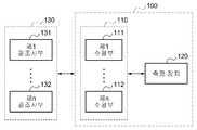
도 1은 고정밀 신호 센싱 시스템의 구성을 도시한 도면이다.1 is a diagram showing a configuration of a high-precision signal sensing system.
도 1을 참조하면, 고정밀 신호 센싱 시스템(100)는 수광 장치(110) 및 측정 장치(120)를 포함한다.Referring to FIG. 1, a high-precision
수광 장치(110)는 발광 장치(130)로부터 제1 광 및 제2 광을 포함하는 복수의 조사광을 수광한다. 여기서, 발광 장치(130)는 1개 이상의 광조사부(131, 132)를 포함할 수 있고, 수광 장치(110) 또한 1개 이상의 수광부(111, 112)를 포함할 수 있다. 광조사부(131, 132)는 예컨대, 엘이디(LED)로서, 적외선 신호를 조사할 수 있고, 수광부(111, 112)는 예컨대, 포토다이오드(Photodiode)로서, 조사된 적외선 신호를 센싱할 수 있다.The
일 실시예로, 수광 장치(110) 내 수광부(111)가 발광 장치(130) 내 광조사부(131, 132) 보다 상대적으로 소수 개일 경우(예컨대 광조사부 2개, 수광부 1개), 수광 장치(110)는 개별의 광조사부(131, 132)에서 조사되는 상기 제1 광과 상기 제2 광을, 단일의 수광부(111)로 수광할 수 있다.In one embodiment, when the
이때, 발광 장치(130) 내 광조사부(131, 132) 각각은, 동일한 방향을 가지고 배열하되, 상이한 지향성을 갖는 필드를 형성할 수 있다. 즉, 광조사부(131, 132) 각각이 동일한 방향으로 배열되면, 발광 장치(130)는 동일한 방향으로 복수의 조사광을 조사하되, 광조사부(131, 132) 각각이 상이한 지향성을 갖는 필드를 형성 함에 따라, 서로 다른 세기의 복수 조사광을 조사할 수 있다. 발광 장치(130)는 제1, 2 광에 대해, 시분할, 코딩, 광 파장 등을 이용하여 서로 구분되어 조사되도록 한다.At this time, each of the
다른 실시예로, 수광 장치(110) 내 수광부(111, 112)가, 발광 장치(130) 내 광조사부(131) 보다 상대적으로 다수 개일 경우(예컨대 광조사부 1개, 수광부 2개), 수광 장치(110)는 광조사부(131 또는 132)에서 조사되는 상기 제1 광과 상기 제2 광 각각을, 수광부(111, 112)에서 개별적으로 수광할 수 있다.In another embodiment, when the number of the
이때, 수광 장치(110) 내 수광부(111, 112) 각각은, 동일한 방향을 가지고 배열하되, 상이한 지향성을 갖는 필드를 형성할 수 있다. 즉, 수광 장치(110)는 내부의 수광부(111, 112) 각각을 동일한 방향으로 배열하여 동일한 수광방향으로 복수의 조사광을 수광하되, 수광부(111, 112) 각각이 상이한 지향성을 갖는 필드를 형성 함에 따라, 방향 별로 세기가 서로 다른 복수의 조사광을 수광할 수 있다.At this time, each of the
다른 예로서, 수광 장치 내 수광부(111, 112) 각각은, 상이한 방향을 가지고 배열하되, 동일한 지향성을 갖는 필드를 형성할 수도 있다. 즉, 수광 장치(110)는, 수광부(111, 112) 각각이 동일한 지향성을 갖는 필드를 형성하더라도, 수광부(111, 112) 각각이 상이한 방향으로 배열 됨에 따라, 방향 별로 세기가 서로 다른 복수의 조사광을 수광할 수 있다.As another example, each of the
측정 장치(120)는 복수의 조사광이 수광되면, 발광 장치(130)과의 이격된 거리 및 상기 조사광의 수신방향에 따른, 상기 제1 광 및 제2 광 각각의 수광 세기를 측정하고, 상기 수광 세기 간의 차이 세기를 이용하여, 대상체로서의 발광 장치(130)를 추정하기 위한 지향 방향별 광을 측정한다.When the plurality of irradiation lights are received, the
예컨대, 측정 장치(120)는 상기 제1 광에 대해 측정된 제1 수광 세기, 또는 상기 제2 광에 대해 측정된 제2 수광 세기가, 제1, 2 수광 세기 간의 차이 세기 보다 작은 지향 방향의 영역에서, 상기 차이 세기에 상응하는 광을 발광 장치(130)의 지향 방향별 광으로 측정할 수 있다. 여기서, 상기 차이 세기에 상응하는 광은 제1 광에 포함되는 잡음과, 제2 광에 포함되는 잡음이 상쇄되어, 신호대 잡음비(SNR)가 높게 형성된다. 이에 따라, 측정 장치(120)는 신호대 잡음비가 높은, 상기 차이 세기의 광을 이용하여, 지향 방향별 광을 측정 함으로써, 일정한 레벨의 신호 세기가 유지되는 광을 활용하여 대상체를 정밀도 높게 추정할 수 있는 환경을 마련한다.For example, the
반면, 측정 장치(120)는 상기 제1 광에 대해 측정된 제1 수광 세기, 또는 상기 제2 광에 대해 측정된 제2 수광 세기가, 제1, 2 수광 세기 간의 차이 세기 보다 작지 않은 지향 방향의 영역의 경우, 상기 제1 수광 세기 또는 상기 제2 수광 세기에 상응하는 광을 지향 방향별 광으로 측정할 수 있다. 예컨대, 측정 장치(120)는 제1 수광 세기 및 제2 수광 세기 중에서, 발광 장치와 수광 장치가 정면으로 마주 보는 가상 축을 기준으로 어긋나는 크기가 증가 함에 따라 세기가 급격하게 떨어지는(즉 분해능이 우수한) 세기를 선택하고, 선택된 세기의 광을 발광 장치(130)를 추정하기 위한 지향 방향별 광으로 측정 할 수 있다.On the other hand, the
구체적으로, 발광 장치(130) 내 광조사부(131, 132) 각각이 동일한 방향으로 배열되고, 상이한 지향성을 갖는 필드를 형성하는 경우, 측정 장치(120)는 상기 형성된 필드가 수광 장치(110) 내 수광부(111, 112)와 연관된 필드와 교차되는 상태하에서, 수광부(111, 112)와 각 광조사부(131, 132)와의 거리, 및 수광방향 또는 발광방향에 따른 복수의 수광 세기를 측정할 수 있다.Specifically, when each of the
또한, 다른 일례로서, 수광 장치(110) 내 수광부(111, 112) 각각이 동일한 방향으로 배열되고, 상이한 지향성을 갖는 필드를 형성하거나, 또는 수광 장치(110) 내 수광부(111, 112) 각각이 상이한 방향으로 배열되고, 동일한 지향성을 갖는 필드를 형성하는 경우, 측정 장치(120)는 상기 형성된 필드가 발광 장치(130) 내 광조사부(131, 132)와 연관된 필드와 교차되는 상태하에서, 각 수광부(111, 112)와 광조사부(131, 132)와의 거리, 및 수광방향 또는 발광방향에 따른 복수의 수광 세기를 측정할 수 있다.As another example, it is also possible that the
또한, 측정 장치(120)는 조사광 각각에 대한 수광 세기 간의 차이 세기와 함께, 상기 조사광과 관련하여, 수광 장치(110)에서의 수광 지향성, 또는 발광 장치(130)에서의 발광 지향성을 더 이용하여, 발광 장치(130)를 추정하는 데에 활용되는 지향 방향별 광을 측정 할 수 있다. 여기서, 수광 지향성은 수광부(111, 112)에서 조사광을 수광할 때의 지향 방향에 따라 수광되는 세기가 달라지는 특성이고, 발광 지향성은 광조사부(131, 132)에서 조사광을 조사할 때의 지향 방향에 따라 수광되는 세기가 달라지는 특성일 수 있다.In addition, the
도 2는 적외선 신호의 발광 지향 방향에 따라 적외선의 수광 세기가 달라지는 적외선의 발광 지향 특성을 도시한 도면이다.FIG. 2 is a diagram showing the light emission directivity characteristic of infrared rays in which the light receiving intensity of the infrared ray is changed according to the light emission directing direction of the infrared ray signal.
도 2를 참조하면, 적외선은 정해진 거리에서 적외선 신호의 지향 방향인 광조사부의 방향각에 따라 적외선의 수광 세기가 달라지는 특성을 가진다. 도 2에서 Z축은 발광 적외선의 세기를 나타내고, X축과 Y축은 수광부에서 광조사부를 측정하는 측정 각도를 나타낸다.Referring to FIG. 2, the infrared ray has a characteristic that the light receiving intensity of the infrared ray varies according to the direction angle of the light irradiating part, which is the direction of the infrared ray signal at a predetermined distance. In Fig. 2, the Z axis represents the intensity of the emitted infrared rays, and the X axis and the Y axis represent measurement angles for measuring the light irradiated portion in the light receiving portion.
도 3은 적외선 신호의 발광 지향성 및 수광 지향성을 도시한 도면이다.3 is a diagram showing the light directivity and the light directivity of the infrared signal.
도 3을 참조하면, A와 B의 수광 세기를 비교하면 알 수 있듯이 적외선 신호의 수광 세기는 광조사부에서의 발광 지향 방향각(θ)에 따라 달라진다. 또한, 적외선 신호의 수광 세기는 수광부에서 적외선 신호를 수광하는 방향인 수광 지향 방향각(ψ)에 따라서도 영향을 받을 수 있다.Referring to FIG. 3, as can be seen from the comparison of the received light intensities of A and B, the light receiving intensity of the infrared signal differs according to the light emitting direction angle? In the light irradiating portion. The light receiving intensity of the infrared signal may also be influenced by the light receiving direction angle (ψ), which is the direction of receiving the infrared signal at the light receiving section.
광조사부와 수광부 사이의 거리에 따라 측정되는 신호의 세기는 아래 <수학식 1>과 같은 특성을 가진다.The intensity of the signal measured according to the distance between the light irradiating part and the light receiving part has the following characteristics.

여기서, I는 측정되는 신호의 세기이고, r은 광조사부와 수광부 사이의 거리이다.Where I is the intensity of the signal being measured and r is the distance between the light irradiating portion and the light receiving portion.
광조사부의 지향 방향에 따라 측정되는 신호의 세기는 아래 <수학식 2>과 같은 특성을 가진다.The intensity of the signal measured according to the direction of the light irradiation unit has the following Equation (2).

여기서, I는 측정되는 신호의 세기이고, κ는 광조사부의 감쇄 특성을 나타내는 변수이고, θ는 광조사부가 지향하는 방향각이다.Here, I is the intensity of the signal to be measured, κ is a variable indicating the attenuation characteristic of the irradiated portion, and θ is the direction angle that the irradiated portion is directed to.
수광부의 지향 방향에 따라 측정되는 신호의 세기는 아래 <수학식 3>과 같은 특성을 가진다.The intensity of the signal measured according to the direction of the light receiving unit has the following Equation (3).

여기서, I는 측정되는 신호의 세기이고, λ는 수광부의 감쇄 특성을 나타내는 변수이고, ψ는 수광부가 지향하는 방향각이다.Here, I is the intensity of the signal to be measured, [lambda] is a variable indicating the attenuation characteristic of the light receiving portion, and [psi] is a direction angle directed by the light receiving portion.
그러면, 광조사부와 수광부 사이의 거리와 광조사부의 지향 방향, 수광부의 지향 방향에 따른 특성을 모두 고려하여 측정되는 적외선의 신호 세기는 아래 <수학식 4>와 같이 측정할 수 있다.Then, the signal intensity of the infrared ray, which is measured in consideration of the distance between the light irradiating unit and the light receiving unit, the direction of the light irradiating unit, and the direction of the light receiving unit, can be measured as shown in Equation (4) below.

여기서, I는 측정되는 신호의 세기이고, r은 광조사부와 수광부 사이의 거리이고, α는 광조사부와 수광부의 특성을 고려한 스케일 팩터이고, κ는 광조사부의 감쇄 특성을 나타내는 변수이고, θ는 광조사부가 지향하는 방향각이고, λ는 수광부의 감쇄 특성을 나타내는 변수이고, ψ는 수광부가 지향하는 방향각이다.Here, I is the intensity of the signal to be measured, r is the distance between the light irradiating part and the light receiving part,? Is a scale factor considering the characteristics of the light irradiating part and the light receiving part,? Is a variable indicating the attenuation characteristic of the light irradiating part, ? Is a variable indicating the attenuation characteristic of the light receiving portion, and? Is a directional angle toward which the light receiving portion is directed.
도 4는 고정밀 신호 센싱 시스템의 일례를 도시한 도면이다.4 is a diagram showing an example of a high-precision signal sensing system.
도 4를 참조하면, 고정밀 신호 센싱 시스템(400)은 1개의 수광부(401)를 이용하여, 발광 장치(410) 내 동일한 방향으로 배열된 2개의 광조사부(411, 412)로부터 2개의 조사광을 수광할 수 있다. 여기서, 2개의 광조사부(411, 412)는 상이한 지향성을 갖는 필드를 형성하여, 세기가 서로 다른 2개의 조사광을 조사할 수 있다. 이에 따라, 고정밀 신호 센싱 시스템(400)은 세기가 다른 2개의 조사광을 수광할 수 있다.4, the high-precision
고정밀 신호 센싱 시스템(400)은 수광 세기가 다른 상기 2개의 조사광을 이용하여, 발광 장치를 추정하는 데에 활용되는 지향 방향별 광(조사광)을 측정할 수 있다. 구체적으로, 고정밀 신호 센싱 시스템은 2개의 조사광 중 제1 광에 대해 측정된 제1 수광 세기, 또는 제2 광에 대해 측정된 제2 수광 세기가, 제1, 2 수광 세기 간의 차이 세기 보다 작지 않은 지향 방향의 영역의 경우, 제1 수광 세기 또는 제2 수광 세기에 상응하는 광을, 해당 영역에서의 지향 방향별 광으로 측정할 수 있다. 이때, 고정밀 신호 센싱 시스템(400)은 제1 수광 세기 또는 제2 수광 세기 중, 분해능이 보다 우수한 광조사부의 것을 선택하여, 지향 방향의 변화에 따라 수광되는 세기가 민감하게 달라지는 조사광을 선택적으로 측정할 수 있다.The high-precision
반면, 고정밀 신호 센싱 시스템(400)은 2개의 조사광 중 제1 광에 대해 측정된 제1 수광 세기, 또는 제2 광에 대해 측정된 제2 수광 세기가, 제1, 2 수광 세기 간의 차이 세기 보다 작은 지향 방향의 영역의 경우, 상기 차이 세기에 상응하는 광을 해당 영역에서의 지향 방향별 광으로 측정할 수 있다.On the other hand, in the high-precision
도 5는 수광부의 방향 별 조사광에 대한 수광 세기의 일례를 도시한 도면이다.5 is a diagram showing an example of the light receiving intensity with respect to the irradiation light for each direction of the light receiving portion.
도 5를 참조하면, 고정밀 신호 센싱 시스템은 제1 광에 대해 측정된 제1 수광 세기(Intensity), 또는 제2 광에 대해 측정된 제2 수광 세기가, 제1, 2 수광 세기 간의 차이 세기(difference) 보다 작지 않은 지향 방향의 영역, 즉 도번 (501)에서, 분해능이 보다 우수한 광조사부의 제1 수광 세기에 상응하는 광을 측정할 수 있다.Referring to FIG. 5, the high-precision signal sensing system may measure the first light intensity measured for the first light, or the second light received intensity measured for the second light, the light corresponding to the first light-receiving intensity of the light-irradiating portion having a better resolution can be measured in the region of the direction of direction not smaller than the difference between the first and second directions.
반면, 고정밀 신호 센싱 시스템은 제1 광에 대해 측정된 제1 수광 세기, 또는 제2 광에 대해 측정된 제2 수광 세기가, 제1, 2 수광 세기 간의 차이 세기 보다 작은 지향 방향의 영역, 즉 도번 (502)에서, 상기 차이 세기에 상응하는 광을 선택적으로 측정할 수 있다.On the other hand, in the high-precision signal sensing system, the first light-receiving intensity measured with respect to the first light, or the second light-receiving intensity measured with respect to the second light is a region in the direction of the direction smaller than the difference intensity between the first and second light- In the
이에 따라, 고정밀 신호 센싱 시스템은 잡음이 상쇄되어, 신호대 잡음비(SNR)가 일정 수준으로 높은 신호 만을 이용하여, 대상체인 발광 장치의 거리와 방향을 정밀하게 추정하는 환경을 조성할 수 있다.Accordingly, the high-precision signal sensing system can cancel the noise and create an environment for precisely estimating the distance and the direction of the light-emitting device as a target by using only a signal having a high SNR (Signal to Noise Ratio).
도 6은 고정밀 신호 센싱 시스템의 다른 일례를 도시한 도면이다.6 is a diagram showing another example of a high-precision signal sensing system.
도 6을 참조하면, 고정밀 신호 센싱 시스템(600)은 (a)에 도시된 바와 같이, 동일한 방향으로 배열되나 상이한 지향성을 갖는 2개의 수광부(601, 602)를 이용하여, 발광 장치(610) 내 1개의 광조사부(611)로부터 2개의 조사광을 수광할 수 있다. 여기서, 2개의 수광부(601, 602)는 상이한 지향성을 갖는 필드를 형성하여, 세기가 서로 다른 2개의 조사광을 각각 수광할 수 있다. 이때, 상기 서로 다른 2개의 조사광은, 시분할, 변조, 광파장 등을 통해 구분되어 조사될 수 있다.6, the high-precision
또한, 고정밀 신호 센싱 시스템(620)는 (b)에 도시된 바와 같이, 동일한 방향으로 배열되나 상이한 지향성을 갖는 2개의 수광부(621, 622)를 이용하여, 발광 장치(630) 내 동일한 방향으로 배열된 2개의 광조사부(631, 632)로부터 2개의 조사광을 수광할 수 있다. 여기서, 2개의 광조사부(631, 632)는 상이한 지향성을 갖는 필드를 형성하여, 세기가 서로 다른 2개의 조사광을 조사하고, 2개의 수광부(621, 622)는 상이한 지향성을 갖는 필드를 형성하여, 세기가 서로 다른 2개의 조사광을 각각 수광할 수 있다.The high-precision
또한, 고정밀 신호 센싱 시스템(640)는 (c)에 도시된 바와 같이, 상이한 방향으로 배열되나 동일한 지향성을 갖는 2개의 수광부(641, 642)를 이용하여, 발광 장치(650) 내 1개의 광조사부(651)로부터 2개의 조사광을 수광할 수 있다. 여기서, 2개의 수광부(641, 642)는 동일한 지향성을 갖는 필드를 형성하나, 상이한 방향으로 배열 됨에 따라, 세기가 서로 다른 2개의 조사광을 각각 수광할 수 있다.The high-precision
고정밀 신호 센싱 시스템은 도 6에 도시한 구성 이외에, 다양한 방법으로 구성될 수 있으며, 조사광에 대한 서로 다른 수광 세기를 이용하여, 일정 수준의 신뢰성 있는 SNR의 신호를 측정 함으로써, 발광 장치에 대한 후속 추정 과정이 보다 정밀하게 이루어지도록 유도 할 수 있다.The high-precision signal sensing system can be configured in various ways in addition to the configuration shown in FIG. 6, and by measuring signals of a certain level of reliable SNR using different light-receiving intensities of the illuminating light, It is possible to induce the estimation process to be performed more precisely.
도 7은 고정밀 신호 센싱 시스템을 이용하여 위치 및 방향을 추정하는 시스템을 도시한 도면이다. 여기서, 위치 및 방향을 추정하는 시스템은, 상술한 고정밀 신호 센싱 시스템을 포함할 수 있다.7 is a diagram illustrating a system for estimating a position and a direction using a high-precision signal sensing system. Here, the system for estimating the position and the direction may include the high-precision signal sensing system described above.
도 7을 참조하면, 위치 및 방향을 추정하는 시스템(700)은 수광부(701, 702, 703)에서 수광된 조사광의 수광방향 또는 거리에 따라 달라지는 세기와 수광 지향성 및 발광 지향성을 이용해서 발광 장치의 위치(x, y, z)와 방향(f, q, y)을 추정한다. 위치 및 방향을 추정하는 시스템(700)의 위치 및 방향의 추정 방법은 아래에서 도 8을 참조해서 상세히 설명하고자 한다.Referring to FIG. 7, the
도 8은 광조사부가 2개인 경우 3차원 위치 및 방향을 추정하기 위한 계산시 필요한 파라메타를 표시한 도면이다.8 is a diagram showing parameters required for calculation for estimating the three-dimensional position and direction when there are two irradiation units.
도 8를 참조하면, 광조사부(711, 712)와 수광부(701)가 지향하고 있는 단위(unit) 방향 벡터를 Global 좌표계에 대해서 각각


또한,


여기서,

여기서,
즉, 2개의 광조사부(711, 712)의 조사광이 짧은 시간 안에 순차적으로 들어오거나 서로 다른 주파수로 수광되는 경우, <수학식 5>와 <수학식 6>의 정보는 독립적으로 얻어진다. 따라서 수광부(701~703)는 각각 2개의 식을 구할 수 있다.That is, when the illuminating light of the two
수광부(701~703)가 3개일 경우는 발광 장치(710)의 위치와 방향에 대해서 6개의 식이 얻어지게 된다.When there are three light receiving
이 중


따라서, 9개의 식으로부터 9개의 미지수를 구하는 문제가 되므로 최적화 기법 등의 수학식을 이용하여 해결 가능하다. 이때 수광부(701~703)의 수가 증가하게 되면 오차를 최소화하는 정규화 문제로 생각할 수 있다.Therefore, since nine unknowns are obtained from nine equations, it can be solved by using an equation such as an optimization technique. At this time, if the number of the
위치 및 방향을 추정하는 시스템(700)은 광조사부(711, 712)가 2개인 경우 수광부(701~703)의 개수에 따라 측정할 수 있는 위치(x, y, z)와 방향(f, q, y)의 종류가 아래 <표 1>과 같이 달라진다. 여기서, x, y, z는 3차원 좌표이고, φ는 z축을 기준으로 하는 각도(roll)이고, θ는 x축을 기준으로 하는 각도(pitch)이고, ψ는 y축을 기준으로 하는 각도(yaw)이다.The

<표 1>을 참조하면, 위치 및 방향을 추정하는 시스템(700)은 광조사부(711, 712)가 2개 이고, 수광부(701~703)가 3개인 경우, 발광 장치(710)의 3차원 위치(x, y, z)와 발광 장치(710)의 3축 방향인 roll(φ), pitch(θ)와 yaw(ψ)를 추정할 수 있다.The
한편, 광조사부와 수광부의 수가 반대인 경우도 이와 동일 하다. 즉, 광조사부가 3개 이고, 수광부가 2개인 경우, 위치 및 방향을 추정하는 시스템(700)은 발광 장치(710)의 3차원 위치(x, y, z)와 발광 장치(710)의 3축 방향인 roll(φ), pitch(θ)와 yaw(ψ)를 추정할 수 있다.The same applies to the case where the number of light irradiating portions and the number of light receiving portions is opposite. That is, the
<표 1>을 참조하면, 위치 및 방향을 추정하는 시스템(700)은 광조사부가 2개이고, 수광부가 2개이고, 발광 장치(710)의 3축의 방향 중에서 roll(φ)이 고정된 경우, 발광 장치(710)의 2차원 평면상의 위치(x, y)와 발광 장치(710)의 2차원 평면상의 방향인 pitch(θ)와 yaw(ψ)를 추정할 수 있다.Referring to Table 1, when the
도 9는 고정밀 신호 센싱 방법을 나타내는 흐름도이다.9 is a flowchart showing a high-precision signal sensing method.
도 9를 참조하면, 단계 901에서, 고정밀 신호 센싱 시스템은 발광 장치로부터의 광을 수광 장치에서 수광한다. 고정밀 신호 센싱 시스템은 발광 장치와 수광 장치 사이의 이격된 거리, 수광방향 등에 따라, 조사광을 제1 광 및 제2 광으로 구분하여 수광한다.Referring to Fig. 9, in
고정밀 신호 센싱 시스템은 다양한 방법으로 조사광을 수광할 수 있다.The high-precision signal sensing system can receive the irradiation light in various ways.
예컨대, 고정밀 신호 센싱 시스템은, 상이한 지향성으로 갖는 2개의 광조사부로부터 조사되는, 상이한 세기의 2개의 조사광을 1개의 수광부를 이용하여 수광할 수 있다.For example, a high-precision signal sensing system can receive two illuminating lights of different intensities, which are emitted from two illuminating sections with different directivities, by using one light receiving section.
또는, 고정밀 신호 센싱 시스템은 동일한 방향으로 배열되나 상이한 지향성을 갖는 2개의 수광부를 이용하여, 하나 이상의 광조사부로부터 2개의 조사광을 수광할 수 있다. 상기 수광부는 상이한 지향성에 의해 상이하게 되는 세기로 2개의 조사광을 수광할 수 있다.Alternatively, the high-precision signal sensing system can receive two irradiating lights from one or more light irradiating parts by using two light receiving parts arranged in the same direction but having different directivity. The light receiving unit can receive two irradiation lights at an intensity differentiated by different directivity.
또는, 고정밀 신호 센싱 시스템은 상이한 방향으로 배열되나 동일한 지향성을 갖는 2개의 수광부를 이용하여, 하나 이상의 광조사부로부터 2개의 조사광을 수광할 수 있다. 상기 수광부는 수광 방향의 변화에 따라, 광조사부로부터의 조사광을 상이한 세기로 수광할 수 있다.Alternatively, the high-precision signal sensing system may receive two irradiation lights from one or more light irradiation parts using two light receiving parts arranged in different directions but having the same directivity. The light receiving section can receive the irradiation light from the light irradiation section at different intensities in accordance with the change of the light reception direction.
단계 903에서, 고정밀 신호 센싱 시스템은 거리와 수광 방향에 따른 제1 광 및 제2 광 각각의 수광 세기를 측정한다.In
여기서, 제1광에 대한 수광 세기와 제2 광에 대한 수광 세기는 서로 상이하다.Here, the light receiving intensity for the first light and the light receiving intensity for the second light are different from each other.
단계 905에서, 고정밀 신호 센싱 시스템은 상기 측정된 수광 세기 또는 상기 수광 세기 간의 차이 세기 중 적어도 하나를 이용하여, 상기 발광 장치를 추정하기 위한 지향 방향별 광을 측정한다.In
고정밀 신호 센싱 시스템은 제1 광에 대해 측정된 제1 수광 세기, 또는 제2 광에 대해 측정된 제2 수광 세기가, 제1, 2 수광 세기 간의 차이 세기 보다 작지 않은 지향 방향에서, 제1 수광 세기 또는 제2 수광 세기에 상응하는 광을 상기 발광 장치를 추정하는 데에 활용되는 지향 방향별 광으로 측정할 수 있다. 예컨대, 고정밀 신호 센싱 시스템은 제1 수광 세기 및 제2 수광 세기 중 분해능이 보다 우수한 광조사부와 연관된 광을 측정할 수 있다.The high-precision signal sensing system is characterized in that the first light-receiving intensity measured with respect to the first light or the second light-receiving intensity measured with respect to the second light is the first light- The light corresponding to the intensity or the second light-receiving intensity can be measured as the light according to the directing direction used for estimating the light-emitting device. For example, a high-precision signal sensing system can measure light associated with a light-irradiating unit having a better resolution than the first light-receiving intensity and the second light-receiving intensity.
반면, 고정밀 신호 센싱 시스템은 제1 광에 대해 측정된 제1 수광 세기, 또는 제2 광에 대해 측정된 제2 수광 세기가, 제1, 2 수광 세기 간의 차이 세기 보다 작은 지향 방향에서, 상기 차이 세기에 상응하는 광을 선택적으로 측정할 수 있다. 여기서, 상기 차이 세기에 상응하는 광은 제1 광에 포함되는 잡음과, 제2 광에 포함되는 잡음이 상쇄되어, 신호대 잡음비(SNR)가 높을 수 있다. 이에 따라, 고정밀 신호 센싱 시스템은 신호대 잡음비가 높은 광을, 지향 방향의 변화에 따라 선택적으로 측정 할 수 있다.On the other hand, in the high-precision signal sensing system, the first light-receiving intensity measured for the first light, or the second light-receiving intensity measured for the second light is smaller than the difference intensity between the first and second light- The light corresponding to the intensity can be selectively measured. Here, the light corresponding to the difference intensity may have a high signal-to-noise ratio (SNR) due to the cancellation of the noise included in the first light and the noise included in the second light. Accordingly, the high-precision signal sensing system can selectively measure the light having a high signal-to-noise ratio according to the change of the direction of the directivity.
나아가, 고정밀 신호 센싱 시스템을 이용하는, 위치 및 방향을 추정하는 시스템에서는, 대상체로서의 발광 장치에 대한 위치 또는 방향을 보다 정확하게 추정할 수 있게 한다.Further, in a system for estimating a position and a direction, which uses a high-precision signal sensing system, it is possible to more accurately estimate the position or direction of a light emitting device as a target object.
본 발명의 실시 예에 따른 방법들은 다양한 컴퓨터 수단을 통하여 수행될 수 있는 프로그램 명령 형태로 구현되어 컴퓨터 판독 가능 매체에 기록될 수 있다. 상기 컴퓨터 판독 가능 매체는 프로그램 명령, 데이터 파일, 데이터 구조 등을 단독으로 또는 조합하여 포함할 수 있다. 상기 매체에 기록되는 프로그램 명령은 본 발명을 위하여 특별히 설계되고 구성된 것들이거나 컴퓨터 소프트웨어 당업자에게 공지되어 사용 가능한 것일 수도 있다.The methods according to embodiments of the present invention may be implemented in the form of program instructions that can be executed through various computer means and recorded in a computer-readable medium. The computer-readable medium may include program instructions, data files, data structures, and the like, alone or in combination. The program instructions recorded on the medium may be those specially designed and configured for the present invention or may be available to those skilled in the art of computer software.
이상과 같이 본 발명은 비록 한정된 실시예와 도면에 의해 설명되었으나, 본 발명은 상기의 실시예에 한정되는 것은 아니며, 본 발명이 속하는 분야에서 통상의 지식을 가진 자라면 이러한 기재로부터 다양한 수정 및 변형이 가능하다.While the invention has been shown and described with reference to certain preferred embodiments thereof, it will be understood by those of ordinary skill in the art that various changes in form and details may be made therein without departing from the spirit and scope of the invention as defined by the appended claims. This is possible.
그러므로, 본 발명의 범위는 설명된 실시예에 국한되어 정해져서는 아니 되며, 후술하는 특허청구범위뿐 아니라 이 특허청구범위와 균등한 것들에 의해 정해져야 한다.Therefore, the scope of the present invention should not be limited to the described embodiments, but should be determined by the equivalents of the claims, as well as the claims.
100: 고정밀 신호 센싱 시스템
110: 수광 장치
120: 측정 장치
130: 발광 장치100: High-precision signal sensing system
110: Light receiving device
120: Measuring device
130: Light emitting device
Claims (12)
Translated fromKorean상기 제1 광 및 제2 광 각각에 대한 세기를 측정하고, 상기 제1 광 및 상기 제2 광 각각의 측정된 세기 및 상기 측정된 세기들 간의 차이 세기 중 적어도 하나를 이용하여, 상기 발광 장치를 포함하는 대상체의 위치 및 방향 중 적어도 하나를 추정하는 측정 장치
를 포함하고,
상기 제1 광 및 상기 제2 광 각각의 측정된 세기는
상기 수광 장치의 수신 방향, 상기 발광 장치의 발광 방향 및 상기 발광 장치와 상기 수광 장치 간의 거리 중 적어도 하나에 기초하는,
고정밀 신호 센싱 시스템.A light receiving device for receiving the first light and the second light from the light emitting device including a plurality of light irradiation portions having different directivity or different light emission directions; And
Measuring the intensity for each of the first light and the second light and using at least one of a measured intensity of each of the first light and the second light and a difference intensity between the measured intensities, A measuring device for estimating at least one of a position and a direction of an object
Lt; / RTI >
The measured intensity of each of the first light and the second light is
Based on at least one of a receiving direction of the light receiving device, a light emitting direction of the light emitting device, and a distance between the light emitting device and the light receiving device,
High precision signal sensing system.
상기 측정 장치는,
상기 제1 광에 대해 측정된 제1 세기, 또는 상기 제2 광에 대해 측정된 제2 세기가, 상기 차이 세기 보다 작은 지향 방향에서,
상기 차이 세기에 상응하는 광을 지향 방향별 광으로 측정함으로써 상기 대상체의 위치 및 방향 중 적어도 하나를 추정하는 고정밀 신호 센싱 시스템.The method according to claim 1,
The measuring device includes:
Wherein a first intensity measured with respect to the first light or a second intensity measured with respect to the second light is less than the difference intensity,
And estimating at least one of a position and a direction of the object by measuring light corresponding to the difference intensity as light per direction.
상기 측정 장치는,
상기 제1 광에 대해 측정된 제1 세기, 또는 상기 제2 광에 대해 측정된 제2 세기가, 상기 차이 세기 보다 작지 않는 지향 방향에서,
상기 제1 세기 또는 상기 제2 세기에 상응하는 광을, 지향 방향별 광으로 측정함으로써 상기 대상체의 위치 및 방향 중 적어도 하나를 추정하는, 고정밀 신호 센싱 시스템.The method according to claim 1,
The measuring device includes:
Wherein a first intensity measured for the first light, or a second intensity measured for the second light, is less than the difference intensity,
And estimates at least one of a position and a direction of the object by measuring light corresponding to the first intensity or the second intensity as light per directional direction.
상기 발광 장치는
상이한 지향성으로 상기 제1 광 및 상기 제2 광을 광 형태로 송신하는 광조사부를 포함하는, 고정밀 신호 센싱 시스템.The method according to claim 1,
The light-
And a light irradiating portion for transmitting the first light and the second light in optical form with different directivity.
상기 광조사부는,
시분할, 코딩 또는 광 파장 중 적어도 하나를 이용하여 상기 제1 광과 제2 광을 구분하여 발광하는, 고정밀 신호 센싱 시스템.5. The method of claim 4,
The light-
And separates the first light and the second light using at least one of time division, coding, and optical wavelength to emit light.
상기 수광 장치는,
상이한 지향성으로 상기 제1 광과 상기 제2 광을 수광하거나, 또는 동일한 지향성이지만 상이한 수신방향으로 상기 제1 광과 상기 제2 광을 수광하는 수광부를 포함하는, 고정밀 신호 센싱 시스템.The method according to claim 1,
The light-
And a light receiving unit that receives the first light and the second light with different directivity, or receives the first light and the second light in the same direction but in different reception directions.
상기 제1 광에 대한 제1 수광 세기와, 상기 제2 광에 대한 제2 수광 세기를 측정하고, 상기 제1 수광 세기, 상기 제2 수광 세기 및 상기 제1 수광 세기와 상기 제2 수광 세기 간의 차이 세기 중 적어도 하나를 이용하여, 상기 발광 장치를 포함한 대상체의 위치 및 방향 중 적어도 하나를 추정하는 측정 장치
를 포함하고,
상기 제1 광 및 상기 제2 광 각각의 측정된 세기는
상기 수광 장치의 수신 방향, 상기 발광 장치의 발광 방향 및 상기 발광 장치와 상기 수광 장치 간의 거리 중 적어도 하나에 기초하는 고정밀 신호 센싱 시스템.A light receiving device for separately receiving the irradiation light from the light emitting device into the first light and the second light through a plurality of light receiving portions having different directivity or different light receiving directions; And
A first light receiving intensity for the first light and a second light receiving intensity for the second light are measured, and the first light receiving intensity, the second light receiving intensity, and the second light receiving intensity And a difference intensity to estimate at least one of a position and a direction of a target including the light emitting device
Lt; / RTI >
The measured intensity of each of the first light and the second light is
Wherein the light receiving device is based on at least one of a receiving direction of the light receiving device, a light emitting direction of the light emitting device, and a distance between the light emitting device and the light receiving device.
상기 측정 장치는,
상기 제1 수광 세기, 또는 상기 제2 수광 세기가, 상기 차이 세기 보다 작은 경우, 상기 차이 세기에 상응하는 광을, 지향 방향별 광으로 측정함으로써 상기 대상체의 위치 및 방향 중 적어도 하나를 추정하고,
상기 제1 수광 세기, 또는 상기 제2 수광 세기가, 상기 차이 세기 보다 작지 않은 경우, 상기 제1 수광 세기 또는 상기 제2 수광 세기에 상응하는 광을, 상기 지향 방향별 광으로 측정함으로써 상기 대상체의 위치 및 방향 중 적어도 하나를 추정하는, 고정밀 신호 센싱 시스템.9. The method of claim 8,
The measuring device includes:
Estimating at least one of a position and a direction of the object by measuring light corresponding to the difference intensity as light according to the directing direction when the first light receiving intensity or the second light receiving intensity is smaller than the difference intensity,
By measuring light corresponding to the first light receiving intensity or the second light receiving intensity as light per the directing direction when the first light receiving intensity or the second light receiving intensity is not smaller than the difference intensity, And estimates at least one of a position, a position, and a direction.
상기 제1 광 및 상기 제2 광 각각에 대한 세기를 측정하는 단계; 및
상기 제1 광 및 상기 제2 광 각각의 측정된 세기 및 상기 측정된 세기들 간의 차이 세기 중 적어도 하나를 이용하여, 상기 발광 장치를 포함한 대상체의 위치 및 방향 중 적어도 하나를 추정하는 단계
를 포함하고,
상기 제1 광 및 상기 제2 광 각각의 측정된 세기는
상기 수광 장치의 수신 방향, 상기 발광 장치의 발광 방향 및 상기 발광 장치와 상기 수광 장치 간의 거리 중 적어도 하나에 기초하는 고정밀 신호 센싱 방법.Receiving at the light receiving device a first light and a second light from a light emitting device including a plurality of light irradiation portions having different directivity or different light emission directions;
Measuring an intensity for each of the first light and the second light; And
Estimating at least one of a position and a direction of a target including the light emitting device using at least one of a measured intensity of each of the first light and the second light and a difference intensity between the measured intensities
Lt; / RTI >
The measured intensity of each of the first light and the second light is
Wherein the light receiving device is based on at least one of a receiving direction of the light receiving device, a light emitting direction of the light emitting device, and a distance between the light emitting device and the light receiving device.
상기 대상체의 위치 및 방향 중 적어도 하나를 추정하는 단계는,
상기 제1 광에 대해 측정된 제1 수광 세기, 또는 상기 제2 광에 대해 측정된 제2 수광 세기가, 상기 차이 세기 보다 작은 지향 방향에서, 상기 차이 세기에 상응하는 광을 지향 방향별 광으로 측정함으로써 상기 대상체의 위치 및 방향 중 적어도 하나를 추정하는 단계
를 포함하는 고정밀 신호 센싱 방법.11. The method of claim 10,
Estimating at least one of a position and a direction of the object,
The first light receiving intensity measured with respect to the first light or the second light receiving intensity measured with respect to the second light has a light intensity corresponding to the difference intensity in a direction of directivity smaller than the difference intensity, Estimating at least one of a position and a direction of the object by measurement
Gt; signal. ≪ / RTI >
상기 대상체의 위치 및 방향 중 적어도 하나를 추정하는 단계는,
상기 제1 광에 대해 측정된 제1 수광 세기, 또는 상기 제2 광에 대해 측정된 제2 수광 세기가, 상기 차이 세기 보다 작지 않는 지향 방향에서, 상기 제1 수광 세기 또는 상기 제2 수광 세기에 상응하는 광을, 지향 방향별 광으로 측정함으로써 상기 대상체의 위치 및 방향 중 적어도 하나를 추정하는 단계
를 포함하는 고정밀 신호 센싱 방법.11. The method of claim 10,
Estimating at least one of a position and a direction of the object,
Wherein the first light receiving intensity measured with respect to the first light or the second light receiving intensity measured with respect to the second light is greater than or equal to the first light receiving intensity or the second light receiving intensity Estimating at least one of a position and a direction of the object by measuring the corresponding light by the light in the directing direction
Gt; signal. ≪ / RTI >
Priority Applications (3)
| Application Number | Priority Date | Filing Date | Title |
|---|---|---|---|
| KR1020100138939AKR101815972B1 (en) | 2010-12-30 | 2010-12-30 | Apparatus and method for sensing high precision signal using infrared light |
| US13/280,825US9207778B2 (en) | 2010-12-30 | 2011-10-25 | Apparatus and method for sensing high precision signal using infrared light |
| US14/944,729US9568306B2 (en) | 2010-12-30 | 2015-11-18 | Apparatus and method for sensing high precision signal using infrared light |
Applications Claiming Priority (1)
| Application Number | Priority Date | Filing Date | Title |
|---|---|---|---|
| KR1020100138939AKR101815972B1 (en) | 2010-12-30 | 2010-12-30 | Apparatus and method for sensing high precision signal using infrared light |
Publications (2)
| Publication Number | Publication Date |
|---|---|
| KR20120077105A KR20120077105A (en) | 2012-07-10 |
| KR101815972B1true KR101815972B1 (en) | 2018-01-09 |
Family
ID=46380514
Family Applications (1)
| Application Number | Title | Priority Date | Filing Date |
|---|---|---|---|
| KR1020100138939AActiveKR101815972B1 (en) | 2010-12-30 | 2010-12-30 | Apparatus and method for sensing high precision signal using infrared light |
Country Status (2)
| Country | Link |
|---|---|
| US (2) | US9207778B2 (en) |
| KR (1) | KR101815972B1 (en) |
Families Citing this family (2)
| Publication number | Priority date | Publication date | Assignee | Title |
|---|---|---|---|---|
| US9739864B2 (en)* | 2012-01-03 | 2017-08-22 | Ascentia Imaging, Inc. | Optical guidance systems and methods using mutually distinct signal-modifying |
| WO2013103725A1 (en) | 2012-01-03 | 2013-07-11 | Ascentia Imaging, Inc. | Coded localization systems, methods and apparatus |
Citations (1)
| Publication number | Priority date | Publication date | Assignee | Title |
|---|---|---|---|---|
| US20090259432A1 (en)* | 2008-04-15 | 2009-10-15 | Liberty Matthew G | Tracking determination based on intensity angular gradient of a wave |
Family Cites Families (14)
| Publication number | Priority date | Publication date | Assignee | Title |
|---|---|---|---|---|
| FR2508160A1 (en)* | 1981-06-23 | 1982-12-24 | Cilas | DEVICE FOR DETERMINING THE POSITION OF AN OBJECT |
| JP3123663B2 (en) | 1991-07-24 | 2001-01-15 | 大日本印刷株式会社 | Thermal transfer sheet |
| US5367373A (en)* | 1992-11-19 | 1994-11-22 | Board Of Regents, The University Of Texas System | Noncontact position measurement systems using optical sensors |
| KR20030017039A (en) | 2001-08-23 | 2003-03-03 | 김창균 | System and controling method for detecting location of infrared remote |
| JP2003344012A (en) | 2002-05-29 | 2003-12-03 | Sony Corp | Apparatus and method for position recognition |
| EP2192421A1 (en)* | 2002-07-29 | 2010-06-02 | Nippon Telegraph and Telephone Corporation | Locating system and method for determining position of objects |
| JP4172307B2 (en) | 2003-03-31 | 2008-10-29 | 富士ゼロックス株式会社 | 3D instruction input device |
| JP3123663U (en) | 2006-03-30 | 2006-07-27 | 三幸セミコンダクター株式会社 | 3D position detector |
| JP4238891B2 (en) | 2006-07-25 | 2009-03-18 | コニカミノルタセンシング株式会社 | 3D shape measurement system, 3D shape measurement method |
| KR20090010356A (en) | 2007-07-23 | 2009-01-30 | 엘지전자 주식회사 | Pointing system using light emitting and light receiving diode |
| JP5208692B2 (en) | 2008-11-17 | 2013-06-12 | 本田技研工業株式会社 | Position measuring system and position measuring method |
| JP5088308B2 (en) | 2008-12-03 | 2012-12-05 | 富士通モバイルコミュニケーションズ株式会社 | Input device |
| JP4824799B2 (en) | 2009-08-06 | 2011-11-30 | セイコーインスツル株式会社 | Pointing system |
| JP5740104B2 (en)* | 2010-05-13 | 2015-06-24 | セイコーエプソン株式会社 | Optical position detection device and device with position detection function |
- 2010
- 2010-12-30KRKR1020100138939Apatent/KR101815972B1/enactiveActive
- 2011
- 2011-10-25USUS13/280,825patent/US9207778B2/enactiveActive
- 2015
- 2015-11-18USUS14/944,729patent/US9568306B2/enactiveActive
Patent Citations (1)
| Publication number | Priority date | Publication date | Assignee | Title |
|---|---|---|---|---|
| US20090259432A1 (en)* | 2008-04-15 | 2009-10-15 | Liberty Matthew G | Tracking determination based on intensity angular gradient of a wave |
Also Published As
| Publication number | Publication date |
|---|---|
| US9207778B2 (en) | 2015-12-08 |
| US20120170054A1 (en) | 2012-07-05 |
| US9568306B2 (en) | 2017-02-14 |
| KR20120077105A (en) | 2012-07-10 |
| US20160069668A1 (en) | 2016-03-10 |
Similar Documents
| Publication | Publication Date | Title |
|---|---|---|
| KR101673885B1 (en) | System and Method for estimating position and orientation using infrared light | |
| JP6851679B2 (en) | Systems and methods for sensing distance and / or movement | |
| EP1875268B1 (en) | Device and method for the passive localisation of radiating targets | |
| US6497134B1 (en) | Calibration of an instrument | |
| US20090281765A1 (en) | Method of locating an object in 3d | |
| JP5648050B2 (en) | Two-dimensional and three-dimensional position detection system and sensor | |
| JPH10272127A (en) | Method and device for detecting position in x-ray image formation | |
| WO2009016551A8 (en) | Vehicle positioning measurement system and method | |
| JP2015514982A (en) | Coordinate measuring system and method | |
| US9404999B2 (en) | Localization system and localization method | |
| US20130006120A1 (en) | Marker for a medical navigation system with a laser tracker | |
| JP2014524029A (en) | Positioning system and operating method thereof | |
| KR101815972B1 (en) | Apparatus and method for sensing high precision signal using infrared light | |
| CN104035070A (en) | Visible light positioning system and method | |
| US10674934B2 (en) | Apparatus and method for determining positional information for a medical instrument | |
| JP2015537216A (en) | Two-dimensional and three-dimensional gas temperature distribution measurement method | |
| US20190250242A1 (en) | System for orientation estimation from radio measurements | |
| US20160228198A1 (en) | Tracking system and tracking method using the same | |
| CN103712570A (en) | Detection apparatus | |
| WO2022259536A1 (en) | Position measurement device and position measurement method | |
| JP5277693B2 (en) | Radar equipment | |
| US20110147611A1 (en) | Medical imaging equipment and a measuring method for detecting the position of a conveying device of the medical imaging equipment | |
| CN107835939A (en) | For measuring the sensor device of fluid concentrations and the application of the sensor device | |
| US8219274B2 (en) | 3-dimensional perception system and method for mobile platform | |
| WO2016070115A1 (en) | Opto-acoustic imaging system with detection of relative orientation of light source and acoustic receiver using acoustic waves |
Legal Events
| Date | Code | Title | Description |
|---|---|---|---|
| PA0109 | Patent application | Patent event code:PA01091R01D Comment text:Patent Application Patent event date:20101230 | |
| PG1501 | Laying open of application | ||
| A201 | Request for examination | ||
| PA0201 | Request for examination | Patent event code:PA02012R01D Patent event date:20150518 Comment text:Request for Examination of Application Patent event code:PA02011R01I Patent event date:20101230 Comment text:Patent Application | |
| E902 | Notification of reason for refusal | ||
| PE0902 | Notice of grounds for rejection | Comment text:Notification of reason for refusal Patent event date:20170822 Patent event code:PE09021S01D | |
| E701 | Decision to grant or registration of patent right | ||
| PE0701 | Decision of registration | Patent event code:PE07011S01D Comment text:Decision to Grant Registration Patent event date:20171226 | |
| GRNT | Written decision to grant | ||
| PR0701 | Registration of establishment | Comment text:Registration of Establishment Patent event date:20180102 Patent event code:PR07011E01D | |
| PR1002 | Payment of registration fee | Payment date:20180103 End annual number:3 Start annual number:1 | |
| PG1601 | Publication of registration | ||
| PR1001 | Payment of annual fee | Payment date:20201217 Start annual number:4 End annual number:4 | |
| PR1001 | Payment of annual fee | Payment date:20211220 Start annual number:5 End annual number:5 | |
| PR1001 | Payment of annual fee | Payment date:20221219 Start annual number:6 End annual number:6 | |
| PR1001 | Payment of annual fee | Payment date:20241219 Start annual number:8 End annual number:8 |