KR101812008B1 - An electrolyzer having a porous 3-dimensional mono-polar electrodes, and water treatment method using the electrolyzer having the porous 3-dimensional mono-polar electrodes - Google Patents
An electrolyzer having a porous 3-dimensional mono-polar electrodes, and water treatment method using the electrolyzer having the porous 3-dimensional mono-polar electrodesDownload PDFInfo
- Publication number
- KR101812008B1 KR101812008B1KR1020160031113AKR20160031113AKR101812008B1KR 101812008 B1KR101812008 B1KR 101812008B1KR 1020160031113 AKR1020160031113 AKR 1020160031113AKR 20160031113 AKR20160031113 AKR 20160031113AKR 101812008 B1KR101812008 B1KR 101812008B1
- Authority
- KR
- South Korea
- Prior art keywords
- electrode
- dimensional porous
- power supply
- water
- base material
- Prior art date
- Legal status (The legal status is an assumption and is not a legal conclusion. Google has not performed a legal analysis and makes no representation as to the accuracy of the status listed.)
- Expired - Fee Related
Links
Images


Classifications
- C—CHEMISTRY; METALLURGY
- C02—TREATMENT OF WATER, WASTE WATER, SEWAGE, OR SLUDGE
- C02F—TREATMENT OF WATER, WASTE WATER, SEWAGE, OR SLUDGE
- C02F1/00—Treatment of water, waste water, or sewage
- C02F1/46—Treatment of water, waste water, or sewage by electrochemical methods
- C02F1/461—Treatment of water, waste water, or sewage by electrochemical methods by electrolysis
- C02F1/46104—Devices therefor; Their operating or servicing
- C02F1/46109—Electrodes
- C—CHEMISTRY; METALLURGY
- C02—TREATMENT OF WATER, WASTE WATER, SEWAGE, OR SLUDGE
- C02F—TREATMENT OF WATER, WASTE WATER, SEWAGE, OR SLUDGE
- C02F1/00—Treatment of water, waste water, or sewage
- C02F1/46—Treatment of water, waste water, or sewage by electrochemical methods
- C02F1/461—Treatment of water, waste water, or sewage by electrochemical methods by electrolysis
- C02F1/467—Treatment of water, waste water, or sewage by electrochemical methods by electrolysis by electrochemical disinfection; by electrooxydation or by electroreduction
- C02F1/4672—Treatment of water, waste water, or sewage by electrochemical methods by electrolysis by electrochemical disinfection; by electrooxydation or by electroreduction by electrooxydation
- B—PERFORMING OPERATIONS; TRANSPORTING
- B63—SHIPS OR OTHER WATERBORNE VESSELS; RELATED EQUIPMENT
- B63J—AUXILIARIES ON VESSELS
- B63J4/00—Arrangements of installations for treating ballast water, waste water, sewage, sludge, or refuse, or for preventing environmental pollution not otherwise provided for
- B63J4/002—Arrangements of installations for treating ballast water, waste water, sewage, sludge, or refuse, or for preventing environmental pollution not otherwise provided for for treating ballast water
- C—CHEMISTRY; METALLURGY
- C02—TREATMENT OF WATER, WASTE WATER, SEWAGE, OR SLUDGE
- C02F—TREATMENT OF WATER, WASTE WATER, SEWAGE, OR SLUDGE
- C02F1/00—Treatment of water, waste water, or sewage
- C02F1/46—Treatment of water, waste water, or sewage by electrochemical methods
- C02F1/461—Treatment of water, waste water, or sewage by electrochemical methods by electrolysis
- C02F1/463—Treatment of water, waste water, or sewage by electrochemical methods by electrolysis by electrocoagulation
- C—CHEMISTRY; METALLURGY
- C02—TREATMENT OF WATER, WASTE WATER, SEWAGE, OR SLUDGE
- C02F—TREATMENT OF WATER, WASTE WATER, SEWAGE, OR SLUDGE
- C02F1/00—Treatment of water, waste water, or sewage
- C02F1/46—Treatment of water, waste water, or sewage by electrochemical methods
- C02F1/461—Treatment of water, waste water, or sewage by electrochemical methods by electrolysis
- C02F1/467—Treatment of water, waste water, or sewage by electrochemical methods by electrolysis by electrochemical disinfection; by electrooxydation or by electroreduction
- C02F1/4672—Treatment of water, waste water, or sewage by electrochemical methods by electrolysis by electrochemical disinfection; by electrooxydation or by electroreduction by electrooxydation
- C02F1/4674—Treatment of water, waste water, or sewage by electrochemical methods by electrolysis by electrochemical disinfection; by electrooxydation or by electroreduction by electrooxydation with halogen or compound of halogens, e.g. chlorine, bromine
- C—CHEMISTRY; METALLURGY
- C25—ELECTROLYTIC OR ELECTROPHORETIC PROCESSES; APPARATUS THEREFOR
- C25B—ELECTROLYTIC OR ELECTROPHORETIC PROCESSES FOR THE PRODUCTION OF COMPOUNDS OR NON-METALS; APPARATUS THEREFOR
- C25B11/00—Electrodes; Manufacture thereof not otherwise provided for
- C25B11/02—Electrodes; Manufacture thereof not otherwise provided for characterised by shape or form
- C25B11/03—Electrodes; Manufacture thereof not otherwise provided for characterised by shape or form perforated or foraminous
- C25B11/031—Porous electrodes
- C—CHEMISTRY; METALLURGY
- C25—ELECTROLYTIC OR ELECTROPHORETIC PROCESSES; APPARATUS THEREFOR
- C25B—ELECTROLYTIC OR ELECTROPHORETIC PROCESSES FOR THE PRODUCTION OF COMPOUNDS OR NON-METALS; APPARATUS THEREFOR
- C25B11/00—Electrodes; Manufacture thereof not otherwise provided for
- C25B11/04—Electrodes; Manufacture thereof not otherwise provided for characterised by the material
- C25B11/0442—
- C—CHEMISTRY; METALLURGY
- C25—ELECTROLYTIC OR ELECTROPHORETIC PROCESSES; APPARATUS THEREFOR
- C25B—ELECTROLYTIC OR ELECTROPHORETIC PROCESSES FOR THE PRODUCTION OF COMPOUNDS OR NON-METALS; APPARATUS THEREFOR
- C25B11/00—Electrodes; Manufacture thereof not otherwise provided for
- C25B11/04—Electrodes; Manufacture thereof not otherwise provided for characterised by the material
- C25B11/051—Electrodes formed of electrocatalysts on a substrate or carrier
- C25B11/073—Electrodes formed of electrocatalysts on a substrate or carrier characterised by the electrocatalyst material
- E—FIXED CONSTRUCTIONS
- E04—BUILDING
- E04H—BUILDINGS OR LIKE STRUCTURES FOR PARTICULAR PURPOSES; SWIMMING OR SPLASH BATHS OR POOLS; MASTS; FENCING; TENTS OR CANOPIES, IN GENERAL
- E04H4/00—Swimming or splash baths or pools
- E04H4/12—Devices or arrangements for circulating water, i.e. devices for removal of polluted water, cleaning baths or for water treatment
- E04H4/1209—Treatment of water for swimming pools
- E04H4/1245—Recirculating pumps for swimming pool water
- C—CHEMISTRY; METALLURGY
- C02—TREATMENT OF WATER, WASTE WATER, SEWAGE, OR SLUDGE
- C02F—TREATMENT OF WATER, WASTE WATER, SEWAGE, OR SLUDGE
- C02F1/00—Treatment of water, waste water, or sewage
- C02F1/46—Treatment of water, waste water, or sewage by electrochemical methods
- C02F1/461—Treatment of water, waste water, or sewage by electrochemical methods by electrolysis
- C02F1/46104—Devices therefor; Their operating or servicing
- C02F1/46109—Electrodes
- C02F2001/46133—Electrodes characterised by the material
- C02F2001/46138—Electrodes comprising a substrate and a coating
- C02F2001/46142—Catalytic coating
- C—CHEMISTRY; METALLURGY
- C02—TREATMENT OF WATER, WASTE WATER, SEWAGE, OR SLUDGE
- C02F—TREATMENT OF WATER, WASTE WATER, SEWAGE, OR SLUDGE
- C02F1/00—Treatment of water, waste water, or sewage
- C02F1/46—Treatment of water, waste water, or sewage by electrochemical methods
- C02F1/461—Treatment of water, waste water, or sewage by electrochemical methods by electrolysis
- C02F1/46104—Devices therefor; Their operating or servicing
- C02F1/46109—Electrodes
- C02F2001/46152—Electrodes characterised by the shape or form
- C02F2001/46157—Perforated or foraminous electrodes
- C02F2001/46161—Porous electrodes
- C—CHEMISTRY; METALLURGY
- C02—TREATMENT OF WATER, WASTE WATER, SEWAGE, OR SLUDGE
- C02F—TREATMENT OF WATER, WASTE WATER, SEWAGE, OR SLUDGE
- C02F2101/00—Nature of the contaminant
- C02F2101/30—Organic compounds
- C—CHEMISTRY; METALLURGY
- C02—TREATMENT OF WATER, WASTE WATER, SEWAGE, OR SLUDGE
- C02F—TREATMENT OF WATER, WASTE WATER, SEWAGE, OR SLUDGE
- C02F2103/00—Nature of the water, waste water, sewage or sludge to be treated
- C—CHEMISTRY; METALLURGY
- C02—TREATMENT OF WATER, WASTE WATER, SEWAGE, OR SLUDGE
- C02F—TREATMENT OF WATER, WASTE WATER, SEWAGE, OR SLUDGE
- C02F2103/00—Nature of the water, waste water, sewage or sludge to be treated
- C02F2103/008—Originating from marine vessels, ships and boats, e.g. bilge water or ballast water
- C—CHEMISTRY; METALLURGY
- C02—TREATMENT OF WATER, WASTE WATER, SEWAGE, OR SLUDGE
- C02F—TREATMENT OF WATER, WASTE WATER, SEWAGE, OR SLUDGE
- C02F2201/00—Apparatus for treatment of water, waste water or sewage
- C02F2201/46—Apparatus for electrochemical processes
- C02F2201/461—Electrolysis apparatus
- C02F2201/46105—Details relating to the electrolytic devices
- C02F2201/4616—Power supply
- C02F2201/4617—DC only
- C—CHEMISTRY; METALLURGY
- C02—TREATMENT OF WATER, WASTE WATER, SEWAGE, OR SLUDGE
- C02F—TREATMENT OF WATER, WASTE WATER, SEWAGE, OR SLUDGE
- C02F2303/00—Specific treatment goals
- C02F2303/04—Disinfection
Landscapes
- Engineering & Computer Science (AREA)
- Chemical & Material Sciences (AREA)
- Water Supply & Treatment (AREA)
- Organic Chemistry (AREA)
- Electrochemistry (AREA)
- Chemical Kinetics & Catalysis (AREA)
- Environmental & Geological Engineering (AREA)
- Life Sciences & Earth Sciences (AREA)
- Hydrology & Water Resources (AREA)
- General Chemical & Material Sciences (AREA)
- Architecture (AREA)
- Civil Engineering (AREA)
- Structural Engineering (AREA)
- Materials Engineering (AREA)
- Metallurgy (AREA)
- Health & Medical Sciences (AREA)
- General Health & Medical Sciences (AREA)
- Public Health (AREA)
- Toxicology (AREA)
- Combustion & Propulsion (AREA)
- Mechanical Engineering (AREA)
- Ocean & Marine Engineering (AREA)
- Water Treatment By Electricity Or Magnetism (AREA)
Abstract
Translated fromKoreanDescription
Translated fromKorean이 발명은 처리수 내에 함유된 미생물 등을 살균하는 수처리 기술에 관한 것이며, 더욱 상세하게는 환경 친화적인 공정으로 처리수 내에 함유된 미생물 등을 살균할 수 있도록 구성된 3차원 다공성 단극 전극체 및 이를 구비한 전기살균 필터 및 이를 이용한 수처리 방법에 관한 것이다.The present invention relates to a water treatment technique for sterilizing microorganisms and the like contained in treated water, and more particularly, to a three-dimensional porous unipolar electrode body configured to sterilize microorganisms and the like contained in treated water by an environmentally friendly process, An electric sterilizing filter and a water treatment method using the same.
밸러스트수(ballast water), 우물물, 수돗물, 공업용수, 순수, 초순수, 욕조 수, 수영장 수, 산업 배수 혹은 생활 배수 등에는 다양한 미생물이 존재하며, 보건 및 위생을 목적으로 필요에 따라 이를 제거하는 공정이 도입되고 있다.Various microorganisms exist in ballast water, well water, tap water, industrial water, pure water, ultrapure water, bath water, swimming pool water, industrial water drainage or life drainage. Is introduced.
대한민국 특허등록 제10-1220891호에는 3차원 다공성 복극 전극 및 이를 구비한 전기살균 필터와 이를 이용한 수처리 방법에 대해 공개되어 있다. 이 기술은 3차원 전극이 복극식으로 배열된 것을 특징으로 한다. 그런데, 이 기술은 3차원 전극이 복극식으로 배열됨에 따라, 비선형적으로 발생하는 전류 누설(leakage current) 등의 현상이 증폭, 발생하여 전류효율을 감소시키는 영향이 있다. 또한, 누설전류로 인해 한 전극의 수소극에서 받는 수소 발생 스트레스가 원래 받아야 하는 부분보다 겹쳐져서 복잡하게 일어나기 때문에, 수소발생으로 인한 촉매 코팅의 손실 등이 더욱 극심하고 규명하지 못하는 속도로 일어나는 단점이 있다.Korean Patent Registration No. 10-1220891 discloses a three-dimensional porous bipolar electrode, an electric sterilizing filter having the same, and a water treatment method using the same. This technique is characterized in that three-dimensional electrodes are arranged in a biplane manner. However, this technique has an effect of reducing current efficiency by amplifying and generating a non-linear phenomenon such as a leakage current as the three-dimensional electrodes are arranged in a bi-polar manner. In addition, since the hydrogen generation stress caused by the leakage current of the one electrode is more complicated than that of the original one, the loss of the catalyst coating due to the hydrogen generation occurs at a rate that can not be detected at the extreme have.
따라서, 이 발명은 다수의 기공이 다층 구조로 배열되어 일측과 타측이 서로 연통하는 3차원 구조를 가지며 금속 재질로 구성되어 치수안정성을 갖는 3차원 다공성 모재를 이용하여 제작된 3차원 다공성 단극 전극체를 이용해 처리수 내에 함유된 미생물 등을 살균함에 따라 미생물 제거에 요구되는 소비전력을 최소화하는데 그 목적이 있다.Accordingly, the present invention provides a three-dimensional porous unipolar electrode body made of a three-dimensional porous body having a three-dimensional structure in which a plurality of pores are arranged in a multi-layer structure and one side and the other side communicate with each other, To minimize the power consumption required for removing microorganisms by sterilizing microorganisms and the like contained in the treated water.
또한, 이 발명은 3차원 다공성 단극 전극체를 이용한 환경 친화적인 미생물 살균 공정으로 전기분해 과정에서 과량의 살균제 예를 들면 차아염소산 나트륨의 발생을 억제하거나 최소화할 수 있어 이를 방류함에 따라 생기는 해역의 2차적인 오염을 방지하는데 다른 목적이 있다.The present invention also provides an environmentally friendly microbial sterilization process using a three-dimensional porous unipolar electrode unit, which can suppress or minimize the generation of an excessive amount of disinfectant such as sodium hypochlorite in the electrolysis process, There is another purpose in preventing secondary contamination.
또한, 이 발명은 3차원 다공성 단극 전극체를 제작함에 있어 금속 재질의 모재를 사용함에 따라 사용기간이 경과되더라도 초기의 치수를 유지하는 전극의 내구성을 확보하는데 또다른 목적이 있다.In addition, the present invention has another object to secure the durability of the electrode maintaining the initial dimension even if the use period is elapsed due to the use of the metal base material in manufacturing the three-dimensional porous unipolar electrode body.
또한, 이 발명은 단극 전극 배열 구조를 가짐에 따라 누설전류를 줄일 수 있어 전류 효율이 향상되고, 향상된 전류 효율은 전기분해 시스템에 들어가는 정류기의 전류를 감소시킬 수 있어 소비 전력량과 부품 소요 금액을 줄일 수 있도록 하는데 또다른 목적이 있다.In addition, since the present invention has a unipolar electrode array structure, the leakage current can be reduced to improve the current efficiency, and the improved current efficiency can reduce the current of the rectifier in the electrolysis system, There is another purpose to make it possible.
또한, 이 발명은 한 전극이 통째로 양극과 음극만을 띄기 때문에, 수소극이 발생하는 전극에서 느끼는 수소 발생 스트레스가 일정하게 유지되는 측면이 있으므로 수명예측 등이 쉬워지도록 하는데 또다른 목적이 있다.In addition, since the present invention has only one anode and one cathode as a whole, the hydrogen generating stress felt by the electrode in which the hydrogen electrode is generated is kept constant, so that life prediction is easily achieved.
또한, 이 발명은 역세나 디스케일 과정을 통해 필터의 상태를 초기 상태로 재생하는 수단을 별도로 구비함에 따라 반영구적으로 사용할 수 있도록 하는데 또다른 목적이 있다.In addition, the present invention has another object to provide a means for regenerating the state of a filter in an initial state through a decimation or descaling process so that it can be used semi-permanently.
상기와 같은 목적을 달성하기 위한 이 발명의 3차원 다공성 단극 전극체는, 다수의 기공이 다층 구조로 배열되어 일측과 타측이 서로 연통하는 3차원 구조를 가지며 금속 재질로 구성되는 3차원 다공성 모재를 각각 구비하는 양극 전극 및 음극 전극과, 상기 양극 전극과 음극 전극을 서로 간에 일정 간격으로 지지하는 절연성의 지지부재를 포함하며, 상기 양극 전극은 상기 3차원 다공성 모재에 코팅되는 전극 촉매층을 갖도록 구성되어, 통전시에 처리수 내에 함유된 미생물을 흡착하여 전기살균함과 더불어 산화제를 발생시켜 살균이 가능한 것을 특징으로 한다.In order to accomplish the above object, the three-dimensional porous unipolar electrode body of the present invention comprises a three-dimensional porous base material having a three-dimensional structure in which a plurality of pores are arranged in a multi-layer structure and one side and the other side communicate with each other, And an insulating support member for supporting the anode electrode and the cathode electrode at regular intervals from each other, wherein the anode electrode is configured to have an electrode catalyst layer coated on the three-dimensional porous base material , The microorganisms contained in the treated water are adsorbed and electrically sterilized in the process, and the sterilization is possible by generating the oxidizing agent.
또한, 이 발명에 따르면, 상기 3차원 다공성 모재는 엉켜져 있는 가느다란 금속선을 일정 두께로 압착하여 구성하거나, 다수의 금속분말을 바인더와 혼합하여 일정 형태로 성형한 후 소결하여 구성한 것을 특징으로 한다.According to the present invention, the three-dimensional porous preform is formed by pressing a tangled metal wire to a predetermined thickness, or a plurality of metal powders are mixed with a binder to form a predetermined shape and then sintered .
또한, 이 발명에 따르면, 상기 3차원 다공성 모재는 0.1 ~ 60㎛의 기공과, 0.5 ~ 5.0mm의 두께를 갖는 것을 특징으로 한다.In addition, according to the present invention, the three-dimensional porous preform has pores of 0.1 to 60 μm and a thickness of 0.5 to 5.0 mm.
또한, 이 발명에 따르면, 상기 3차원 다공성 모재는 탄소, 니켈, 코발트, 티타늄, 지르코늄, 니오븀, 텅스텐, 하프늄, 하스텔로이, 스테인레스 스틸, 철 또는 이들 중 2개 이상을 포함하는 혼합물, 산화물 또는 합금으로 구성되는 것을 특징으로 한다.According to the present invention, the three-dimensional porous base material may be at least one selected from the group consisting of carbon, nickel, cobalt, titanium, zirconium, niobium, tungsten, hafnium, Hastelloy, stainless steel, iron, .
또한, 이 발명에 따르면, 상기 전극 촉매층은 백금, 팔라듐, 로듐, 이리듐, 루테늄, 오스뮴, 탄소, 금, 탄탈륨, 주석, 인듐, 니켈, 텅스텐, 망간 또는 이들 중 2개 이상을 포함하는 혼합물, 산화물 또는 합금으로 구성되는 것을 특징으로 한다.In addition, according to the present invention, the electrode catalyst layer may be formed of at least one of platinum, palladium, rhodium, iridium, ruthenium, osmium, carbon, gold, tantalum, tin, indium, nickel, tungsten, manganese, Or an alloy.
또한, 이 발명에 따르면, 상기 음극 전극은 상기 3차원 다공성 모재에 코팅되는 전극 촉매층을 더 갖는 것을 특징으로 한다.According to the present invention, the cathode electrode further includes an electrode catalyst layer coated on the three-dimensional porous base material.
상기와 같은 목적을 달성하기 위한 이 발명의 전기살균 필터는, 유로를 구비한 유로관과, 상기 유로관 내에 일정 간격을 두고 설치되는 한 쌍의 급전용 전극과, 상기 한 쌍의 급전용 전극에 접속된 상태로 배열되는 1개 이상의 3차원 다공성 단극 전극체, 및 제1, 제2 외부 도선을 통해 상기 한 쌍의 급전용 전극에 직류전류를 공급하는 급전용 직류전원 공급기를 포함하며, 상기 3차원 다공성 단극 전극체는 상기와 같이 구성되는 것을 특징으로 한다.According to an aspect of the present invention, there is provided an electric sterilizing filter including: a flow path tube having a flow path; a pair of power supply electrodes provided at predetermined intervals in the flow path tube; And at least one three-dimensional porous unipolar electrode assembly arranged in a connected state and a power supply DC power supply for supplying a direct current to the pair of power supply electrodes through first and second external leads, Dimensional porous unipolar electrode body is constructed as described above.
상기와 같은 목적을 달성하기 위한 이 발명의 수처리 방법은, 처리수를 상기와 같이 구성된 전기살균 필터를 통해 통과시키되, 상기 처리수의 통과시에 상기 한 쌍의 급전용 전극에 전류를 인가하여 상기 처리수 내에 함유된 미생물을 상기 3차원 다공성 단극 전극체에서 흡착하여 전기살균함과 더불어 산화제를 발생시켜 살균하는 것을 특징으로 한다.According to another aspect of the present invention, there is provided a water treatment method comprising passing treated water through an electric sterilizing filter having the above-described structure, The microorganisms contained in the treated water are adsorbed by the three-dimensional porous unipolar electrode body and sterilized by generating an oxidizing agent.
또한, 이 발명에 따르면, 상기 한 쌍의 급전용 전극에 인가되는 인가 전류의 극성을 일정 주기로 반전시키면서 살균하는 것을 특징으로 한다.In addition, according to the present invention, the polarity of the applied current applied to the pair of power supply electrodes is sterilized while being inverted at a constant cycle.
또한, 이 발명에 따르면, 상기 처리수에 전해질을 첨가한 상태에서 상기 전기살균 필터를 통해 살균하는 것을 특징으로 한다.Further, according to the present invention, sterilization is performed through the electric sterilizing filter in a state where an electrolyte is added to the treated water.
상기와 같은 목적을 달성하기 위한 이 발명의 밸러스트 수처리 방법은, 해수를 펌핑하여 공급하는 해수 공급 펌프와, 해수 저장용 선박평형수 탱크의 시스템에 상기와 같이 구성된 전기살균 필터와 상기 해수를 전기분해하여 차아염소산을 1000ppm 이상의 농도로 제조하는 간접 살균기를 더 구비하여 구성한 밸러스트 수처리 시스템에서의 수처리 방법으로서, 상기 해수를 상기 전기살균 필터를 통해 통과시키되, 상기 해수의 통과시에 상기 한 쌍의 급전용 전극에 전류를 인가하여 상기 해수 내에 함유된 미생물을 상기 3차원 다공성 단극 전극체에서 흡착하여 전기살균함과 더불어 산화제를 발생시켜 살균하는 것을 특징으로 한다.According to another aspect of the present invention, there is provided a ballast water treatment method comprising: a seawater supply pump for pumping and supplying seawater; an electrolytic sterilizing filter configured as described above in a system of a ballast water tank for seawater storage; And an indirect sterilizer for producing hypochlorous acid at a concentration of 1000 ppm or more. The water treatment method of the present invention is a water treatment method in a ballast water treatment system comprising an indirect sterilizer for producing hypochlorous acid at a concentration of 1000 ppm or more, The microbes contained in the seawater are adsorbed by the three-dimensional porous unipolar electrode body by applying a current to the electrodes to generate electricity and sterilize the oxidant.
또한, 이 발명에 따르면, 상기 전기살균 필터는 상기 간접 살균기의 전단에 위치하는 것을 특징으로 한다.Further, according to the present invention, the electric sterilizing filter is located at the front end of the indirect sterilizer.
또한, 이 발명에 따르면, 상기 전기살균 필터는 상기 간접 살균기의 후단에 위치하는 것을 특징으로 한다.According to the present invention, the electric sterilizing filter is located at the rear end of the indirect sterilizer.
이 발명은 다수의 기공이 다층 구조로 배열되어 일측과 타측이 서로 연통하는 3차원 구조를 가지며 금속 재질로 구성되어 치수안정성을 갖는 3차원 다공성 모재를 이용하여 제작된 3차원 다공성 단극 전극체를 이용해 처리수 내에 함유된 미생물 등을 살균함에 따라, 미생물 제거에 요구되는 소비전력을 최소화할 수 있으며, 이는 선박 등과 같은 전력이 제한된 공간에서 매우 큰 장점으로 활용될 수 있다.The present invention relates to a three-dimensional porous unipolar electrode body manufactured by using a three-dimensional porous base material having a three-dimensional structure in which a plurality of pores are arranged in a multi-layer structure and one side and the other side communicate with each other, By disinfecting the microorganisms contained in the treated water, the power consumption required for removing the microorganisms can be minimized, and this can be utilized as a great advantage in a limited space such as a ship or the like.
또한, 이 발명은 3차원 다공성 단극 전극체를 이용한 환경 친화적인 미생물 살균공정으로 전기분해 과정에서 과량의 살균제 예를 들면 차아염소산 나트륨의 발생을 억제하거나 최소화할 수 있어 2차 오염을 방지할 수 있다.In addition, the present invention can prevent or minimize the generation of an excessive amount of fungicide such as sodium hypochlorite in an electrolysis process by an environmentally friendly microbial sterilization process using a three-dimensional porous unipolar electrode body, thereby preventing secondary contamination .
또한, 이 발명은 3차원 다공성 단극 전극체를 제작함에 있어 금속 재질의 모재를 사용함에 따라 사용기간이 경과하더라도 초기의 치수를 유지하는 전극의 내구성을 확보할 수 있다.In addition, the present invention uses a base material made of a metal to fabricate a three-dimensional porous unipolar electrode body, thereby ensuring the durability of the electrode maintaining the initial dimension even after the use period has elapsed.
또한, 이 발명은 전극 하나가 단일한 양극 또는 음극을 띄기 때문에 실제적으로 촉매성분이 큰 역할을 하지 않는 수소가 발생하는 음극의 경우 촉매 코팅 없이 전처리 후 사용이 가능하므로, 촉매 코팅량을 절반으로 줄일 수 있는 제작상의 이점이 있다.In addition, since the present invention can be used after pretreatment without a catalyst coating in the case of an anode in which hydrogen is generated which does not substantially act as a catalyst component since a single electrode has a single anode or cathode, the catalyst coating amount is reduced to half There is a manufacturing advantage that can be made.
한편, 종래의 복극 전극은 한 전극이 두 극으로 분리되어 운전됨에 따라 모든 전극의 양쪽 면에서 촉매 코팅이 유사하게 용출되는 경향이 있다. 그런데, 디스케일을 위해 이 발명의 양극과 음극 모두에 촉매 코팅한 후, 디스케일을 위해 극을 교체하여 운전하여도 한 전극에 걸리는 부하가 종래의 복극 전극에 비해 1/2로 줄어들기 때문에, 촉매 코팅의 수명이 1.5배에서 2배 가까이 연장되는 장점이 있다.On the other hand, the conventional bipolar electrode has a tendency that the catalyst coating is similarly eluted on both sides of all electrodes as one electrode is separated and operated. However, even after the catalyst is coated on both the positive electrode and the negative electrode of the present invention for descaling and the electrode is changed for descaling, the load applied to one electrode is reduced to 1/2 of that of the conventional double electrode, The lifetime of the catalyst coating is extended from 1.5 to 2 times.
또한, 이 발명은 종래의 복극 전극 배열 구조에서 나타나는 전류 누설 현상을 감소시킬 수 있는 단극 전극 배열 구조를 가짐에 따라 누설전류를 줄일 수 있어 전류 효율이 향상되고, 향상된 전류 효율은 전기분해 시스템에 들어가는 정류기의 전류를 감소시킬 수 있어 소비 전력량과 부품 소요 금액을 줄일 수 있는 장점이 있다.Further, since the present invention has a unipolar electrode array structure capable of reducing a current leakage phenomenon occurring in a conventional bi-polar electrode array structure, it is possible to reduce a leakage current, thereby improving current efficiency and improving current efficiency The current of the rectifier can be reduced, thereby reducing the amount of power consumed and the amount of parts required.
또한, 이 발명은 누설전류로 예측할 수 없는 비선형적인 전기살균 필터의 성능 구배 등이 전혀 없고, 단극식 배열을 통해 각 전극 한쌍 마다 동일한 메커니즘으로 작동하기 때문에 전극의 성능을 보장함에 있어서 예측가능하고 대응이 가능한 장점이 있다.In addition, the present invention has no performance gradient of the non-linear electric sterilizing filter which can not be predicted by the leakage current, and operates by the same mechanism for each pair of electrodes through the single-pole arrangement. Therefore, This has the advantage.
한편, 누설전류는 복극식 배열의 전극을 갖는 전기살균 필터의 전류효율을 감소시킬 뿐만 아니라 누설전류로 인해 한 전극의 수소극에서 받는 수소 발생 스트레스가 원래 받아야 하는 부분보다 겹쳐져서 복잡하게 일어나기 때문에, 수소발생으로 인한 촉매 코팅의 손실 등이 더욱 극심하고 규명하지 못하는 속도로 일어난다. 그런데, 이 발명은 한 전극이 통째로 양극과 음극만을 띄기 때문에, 수소극에서 발생하는 전극에서 느끼는 수소 발생 스트레스가 일정하게 유지되는 측면이 있으므로 수명예측 등이 쉬워지는 장점이 있다.On the other hand, the leakage current not only reduces the current efficiency of the electric sterilizing filter having a bi-polar arrangement electrode but also complicates the hydrogen generating stress received from the hydrogen electrode of the one electrode due to the leakage current, Loss of catalyst coating due to hydrogen evolution, and the like. However, since the present invention has only one anode as the anode and a cathode as the whole, the hydrogen generation stress felt by the electrode generated in the hydrogen electrode is maintained constantly, so that life prediction is easy.
한편, 종래의 복극 전극의 경우에는 재가공하거나 전극을 교체할 경우 모든 전극을 다 교체해야 하지만, 이 발명의 경우 디스케일을 하지 않는 수소극의 비코팅 모재는 큰 문제가 없으면 반영구적으로 교체 없이 사용할 수 있고, 산소극 모재의 촉매 코팅 상태에 따라 산소극, 즉 양극 쪽의 전극만 교체하여 사용할 수 있으므로 간편하고 비용을 절감할 수 있는 장점이 있다.In the case of the conventional bipolar electrode, all the electrodes must be replaced when reworking or replacing the electrodes. However, in the case of the present invention, the uncoated base material of the negative electrode which does not descale can be used semi-permanently without replacement And the oxygen electrode, that is, the electrode on the anode side can be used by replacing the electrode according to the catalyst coating state of the oxygen electrode base material, so that there is an advantage that it is simple and the cost can be saved.
도 1은 이 발명의 한 실시예에 따른 전기살균 필터의 구성관계를 도시한 개략도이고,
도 2는 도 1에 도시된 3차원 다공성 단극 전극체의 원리를 나타낸 개념도이고,
도 3은 종래의 3차원 다공성 복극 전극의 누설전류(current leakage) 현상을 나타낸 모식도이고,
도 4는 전기분해하는 BWTS에서 각 전극 배열에 따른 전기분해 효율을 나타낸 그래프이고,
도 5는 이 실시예에서 대상 처리수를 전기 살균할 때 전극에 인가되는 전압의 극성을 반전시키는 방법에 대한 그래프이고,
도 6은 이 실시예의 전기살균 필터를 이용한 다른 수처리 시스템의 개략도이고,
도 7은 이 실시예의 전기살균 필터를 이용한 수영장 수처리 시스템의 개략도이고,
도 8은 이 실시예의 전기살균 필터를 이용한 밸러스트 수처리 시스템의 개략도이고,
도 9는 이 실시예의 전기살균 필터를 이용한 다른 밸러스트 수처리 시스템의 개략도이고,
도 10은 이 실시예의 전기살균 필터를 이용한 수영장 수처리 시스템의 개략도이고,
도 11은 이 발명의 실험예에 따른 3차원 다공성 양극 전극 및 음극 전극의 표면을 촬영한 사진들이고,
도 12는 체류시간과 전류밀도와 A. salina의 사멸율의 관계를 나타낸 그래프이고,
도 13은 A. salina 사멸에 대한 차아염소산 나트륨의 영향을 나타낸 그래프이며,
도 14는 소듐치오설페이트로 염소를 중화시켰을 때의 A. salina 사멸율을 나타낸 그래프이다.1 is a schematic view showing a constitutional relationship of an electric sterilizing filter according to an embodiment of the present invention,
Fig. 2 is a conceptual view showing the principle of the three-dimensional porous unipolar electrode body shown in Fig. 1,
3 is a schematic diagram showing a current leakage phenomenon of a conventional three-dimensional porous bipolar electrode,
4 is a graph showing the electrolysis efficiency according to each electrode arrangement in the electrolytic BWTS,
5 is a graph showing a method of reversing the polarity of the voltage applied to the electrode when the object treated water is sterilized in this embodiment,
6 is a schematic view of another water treatment system using the electric sterilizing filter of this embodiment,
7 is a schematic view of a swimming pool water treatment system using the electric sterilizing filter of this embodiment,
8 is a schematic view of a ballast water treatment system using the electric sterilizing filter of this embodiment,
9 is a schematic view of another ballast water treatment system using the electric sterilizing filter of this embodiment,
10 is a schematic view of a swimming pool water treatment system using the electric sterilizing filter of this embodiment,
11 is a photograph of the surface of a three-dimensional porous anode and a cathode according to an experimental example of the present invention,
12 is a graph showing the relationship between the residence time and the current density and the mortality rate of A. salina,
13 is a graph showing the effect of sodium hypochlorite on A. salina death,
14 is a graph showing the death rate of A. salina when neutralizing chlorine with sodium thiosulfate.
아래에서, 이 발명에 따른 3차원 다공성 단극 전극체 및 이를 구비한 전기살균 필터 및 이를 이용한 수처리 방법의 양호한 실시예를 첨부한 도면을 참조하여 상세히 설명한다.DETAILED DESCRIPTION OF THE PREFERRED EMBODIMENTS Hereinafter, preferred embodiments of a three-dimensional porous unipolar electrode assembly according to the present invention, an electric sterilizing filter having the same, and a water treatment method using the same will be described in detail with reference to the accompanying drawings.
도 1은 이 발명의 한 실시예에 따른 전기살균 필터의 구성관계를 도시한 개략도이고, 도 2는 도 1에 도시된 3차원 다공성 단극 전극체의 원리를 나타낸 개념도이다.FIG. 1 is a schematic view showing a constitutional relationship of an electric sterilizing filter according to an embodiment of the present invention, and FIG. 2 is a conceptual view showing the principle of a three-dimensional porous unipolar electrode body shown in FIG.
도 1에 도시된 바와 같이, 이 실시예에 따른 전기살균 필터(100)는 그 전단 및 후단이 개방된 구조를 갖는다. 즉, 전기살균 필터(100)는 대상 처리수가 그 전단으로 유입되어 전기살균 처리된 후 후단으로 배출되도록 구성된다.As shown in Fig. 1, the
전기살균 필터(100)는 일정 폭과 길이를 갖는 유로를 구비한 유로관(110)과, 유로관(110) 내에 일정 간격을 두고 설치되는 한 쌍의 급전용 전극(120, 130)과, 한 쌍의 급전용 전극(120, 130) 사이에 배열되는 1개 또는 1개 이상의 3차원 다공성 단극 전극체(140)와, 일측은 한 쌍의 급전용 전극(120, 130)에 밀착되고 타측은 3차원 다공성 단극 전극체(140)에 밀착되어 3차원 다공성 단극 전극체(140)가 순차적으로 양극 전극 또는 음극 전극을 갖도록 하는 다수개의 절연부재(150), 및 제1, 제2 외부 도선(170, 180)을 통해 한 쌍의 급전용 전극(120, 130)에 직류전류를 공급하는 급전용 직류전원 공급기(160)로 구성된다.The
여기서, 유로관(110)은 그 단면이 원형을 비롯하여 다각형 형태를 갖는 것으로서, 전기가 통하지 않는 비전도성 재질로 구성된다. 급전용 전극(120, 130)은 처리수가 잘 유동할 수 있는 메쉬 형태로 구성된 것으로서, 그 일측에 제1, 제2 외부도선(170, 180)이 접속된다. 이때, 제1, 제2 외부도선(170, 180)은 유로관(110)에 구멍을 형성하고 그곳을 통해 급전용 전극(120, 130)에 접속된다.Here, the
3차원 다공성 단극 전극체(140)는 한 개의 전극에 인가해 주는 전류방향에 따라 산화 환원의 한쪽의 극 성분을 각각 띄게 되는 양극 및 음극을 쌍으로 구성한 것으로서, 다공성을 갖도록 구성된다. 즉, 이 실시예의 3차원 다공성 단극 전극체(140)는 다수의 기공이 다층 구조로 배열되어 일측과 타측이 서로 연통하는 3차원 구조를 가지며 금속 재질로 구성되는 3차원 다공성 모재를 각각 구비하는 양극 전극(141) 및 음극 전극(142)으로 구성하되, 양극 전극(141)은 3차원 다공성 모재에 코팅되는 전극 촉매층을 반드시 갖도록 구성되어 통전시에 처리수 내에 함유된 미생물을 흡착하여 전기살균함과 더불어 산화제를 발생시켜 살균이 가능하도록 구성되고, 음극 전극(142)은 3차원 다공성 모재에 코팅되는 전극 촉매층을 선택적으로 갖도록 구성된다.The three-dimensional porous
한편, 3차원 다공성 단극 전극체(140)를 전기살균 필터(100) 내에 포함하지 않고 별도로 구성할 경우에는 양극 전극(141)과 음극 전극(142)을 서로 간에 일정 간격으로 지지하는 절연성의 지지부재(도시안됨)를 포함하여 구성하면 된다.When the three-dimensional porous
여기서, 3차원 다공성 모재는 엉켜져 있는 가느다란 금속선을 일정 두께로 압착하여 구성하거나, 다수의 금속분말을 바인더와 혼합하여 일정 형태로 성형한 후 소결하여 구성한 것이다.Here, the three-dimensional porous base material is constituted by pressing a thin metal wire having a tangled bundle to a predetermined thickness or by molding a plurality of metal powders into a predetermined shape by mixing with a binder and sintering.
절연부재(150)는 3차원 다공성 단극 전극체(140)가 순차적으로 양극 전극(141) 또는 음극 전극(142)을 갖도록 3차원 다공성 단극 전극체(140)를 한 쌍의 급전용 전극(120, 130)에 일정 간격으로 각각 고정한다. 한편, 이 실시예의 급전용 전극(120, 130) 및 3차원 다공성 단극 전극체(140)는 전도성 재질로 구성된다.The insulating
따라서, 전류는 급전용 직류전원 공급기(160)에서 제1 외부 도선(170)을 통해 일측의 급전용 전극(120)에 공급되며, 이어서 다수의 3차원 다공성 단극 전극체(140) 층을 거쳐 타측의 급전용 전극(130) 및 제2 외부도선(180)을 거쳐 다시 직류전원 공급기(160)로 이동한다.Accordingly, the current is supplied to the
여기서, 3차원 다공성 단극 전극체(140)는 단극의 특성을 갖는다. 즉, 도 2에 도시된 바와 같이 3차원 다공성 단극 전극체(140)는 하나의 양극 전극(141) 또는 음극 전극(142)의 극성을 각각 띄게 된다.Here, the three-dimensional porous
이 실시예의 전기살균 필터(100)에서의 살균 과정은 다음과 같다.The sterilization process in the
첫째는 미생물을 3차원 다공성 단극 전극체(140)로 흡착하는 과정이다. 둘째는 3차원 다공성 단극 전극체(140)에 접촉한 미생물이 전자를 잃고 산화되면서 그들의 생명활동에 필요한 효소가 파괴되어 1차적으로 직접 소멸되는 과정으로 1차 살균과정이다. 셋째는 3차원 다공성 단극 전극체(140)에서 일어나는 산화 환원반응을 통해 부가적으로 발생한 산화제, 예를 들면 염소, 과산화수소 및 각종 라디칼(하이드록실, 카보네이트)에 의한 2차 살균 과정이다.First, the microorganism is adsorbed by the three-dimensional porous
상기와 같은 3차원 다공성 단극 전극체(140)의 한 특징은 전극에서 미생물을 흡착하고, 전극에 가해준 전압에 의해 살균하는 것이다. 이는 짐머만(Zimmerman)의 연구결과의 미생물 제거 과정으로 추론할 수 있다. 짐머만은 "미생물 세포막 주위에 약 1 Volt의 전위차가 있으면 세포막이 절연 파괴(Dielectric Breakdown)되어 세포안의 내용물이 세포 밖으로 흘러 나가 미생물이 사멸된다"는 연구결과를 발표하였다(Zimmerman, U., G. Pilwat, and F. Riemann, "Dielectric breakdown of cell membranes", Biophys. J. 1974 Nov;14(11):88199.).One characteristic of the three-dimensional porous
3차원 다공성 단극 전극체(140)의 다른 특징은 전해질의 전기화학 촉매 반응에 의해 발생하는 살균제(전기화학 반응에 의해 물 또는 염소이온 등이 산화되어 오존분자, OH·라디칼, HO2(hydroperoxyl radical), 카보네이트 라디칼(Carbonate Radical), 염소 등)을 통해 미생물을 용이하게 제거할 수 있다는 것이다(E nv iron. Sci. & Technol., Vol. 12, No. 1, pp. 79-84, 1978, Environ. Sci. & Technol., Vol. 32, No. 1, pp. 63-70, 1998).Another characteristic of the three-dimensional porous
3차원 다공성 단극 전극체(140)는 3차원 다공성 모재와, 모재에 코팅된 전극 촉매층으로 구성된다. 3차원 다공성 단극 전극체(140) 중에서 양극 전극(141)(산화 반응측 또는 +측)의 촉매층은 다공성 모재에 흡착된 미생물을 전기살균하고, 전해질인 물 또는 소금물을 전기화학적 산화 과정을 통해 살균제인 오존, OH·라디칼, 염소 등을 생성하는 기능을 하며, 음극 전극(142)(환원 반응측 또는 -측)의 촉매층은 물의 환원 반응을 통해 수소를 발생시키는 반응을 한다.The three-dimensional porous
전기화학적 산화와 환원 과정에 동시에 적합한 촉매 금속으로는, 백금, 팔라듐, 로듐, 이리듐, 루테늄, 오스뮴, 탄소, 금, 탄탈륨, 주석, 인듐, 니켈, 텅스텐, 망간, 안티몬, 니오븀, Ebonex 또는 이들 중 2개 이상을 포함하는 혼합물, 산화물 또는 합금 등이 있으며, 가장 바람직하게는 하나 이상의 백금, 이리듐, 루테늄 등의 혼합촉매로 이루어진다.Catalytic metals that are suitable for both electrochemical oxidation and reduction processes include platinum, palladium, rhodium, iridium, ruthenium, osmium, carbon, gold, tantalum, tin, indium, nickel, tungsten, manganese, antimony, niobium, An oxide, an alloy, or the like, and most preferably a mixed catalyst of at least one of platinum, iridium, ruthenium, and the like.
3차원 다공성 모재의 재질로는 도전성 기능과 전기분해 공정에서의 산화-환원 분위기에 대한 내구성을 가지는 물질이면 적합하며, 바람직하게는 탄소, 니켈, 코발트, 티타늄, 안티몬, 지르코늄, 니오븀, 텅스텐, 하프늄, 하스텔로이, 스테인레스 스틸, 철 또는 이들 중 2개 이상을 포함하는 혼합물, 산화물 또는 합금 등이다.As the material of the three-dimensional porous base material, a material having a conductive function and a durability against an oxidation-reduction atmosphere in an electrolysis process is suitable, and preferably, carbon, nickel, cobalt, titanium, antimony, zirconium, niobium, tungsten, hafnium , Hastelloy, stainless steel, iron, or mixtures, oxides or alloys containing two or more of these.
3차원 다공성 모재의 형상은 섬유형태의 금속선, 그래뉼, 입자상의 금속분말 등으로부터 형성된 3차원 구조가 바람직하다. 즉, 3차원 다공성 모재는 섬유와 같이 엉켜져 있는 가느다란 금속선을 일정 두께로 압착하여 구성하거나, 다수의 금속분말을 바인더와 혼합하여 일정 형태로 성형한 후 소결하여 구성할 수 있다. 따라서, 3차원 다공성 모재는 서로 간에 겹쳐짐에 따라 가느다란 금속선들 사이에 형성되거나 소결 시에 타버린 바인더들에 의해 형성된 다수의 기공이 다층 구조로 배열되어 일측과 타측이 서로 연통하는 3차원 구조를 갖는다. 또한, 3차원 다공성 모재는 금속 재질로 구성됨에 따라 사용 기간이 경과하더라도 초기의 치수를 유지하는 치수안정성을 갖는다.The shape of the three-dimensional porous base material is preferably a three-dimensional structure formed from a fibrous metal wire, granules, particulate metal powder, and the like. That is, the three-dimensional porous base material can be constituted by pressing a thin metal wire which is entangled like a fiber with a certain thickness, or by molding a plurality of metal powders into a predetermined form by mixing with a binder and sintering. Accordingly, the three-dimensional porous base material may be formed between fine metal wires as they are superposed on each other, or may have a three-dimensional structure in which a plurality of pores formed by burned binders are arranged in a multi- . In addition, since the three-dimensional porous base material is made of a metal material, the three dimensional porous base material has dimensional stability that maintains initial dimensions even after the use period has elapsed.
3차원 다공성 모재의 두께는 10mm 이하의 두께를 가질 수 있으며, 약 0.25 내지 약 5.0mm의 두께를 가지는 것이 바람직하다. 그 이유는 0.25mm 미만의 경우 기공성 때문에 유입 유량의 압력 강하가 커지는 문제를 갖기 때문이다.The thickness of the three-dimensional porous base material may have a thickness of 10 mm or less, and preferably a thickness of about 0.25 to 5.0 mm. This is because when the flow rate is less than 0.25 mm, the pressure drop of the inflow flow is increased due to porosity.
3차원 다공성 모재의 적당한 기공률은 일반적인 부피비로 약 10% 이상이고, 바람직하게는 약 30% 내지 약 90% 이다. 그 이유는 10% 이하에서는 대상 처리수가 다공성 모재를 통과하는데 압력손실이 발생하여, 원래의 목적인 여과의 기능성을 수행하지 못하게 되고, 90% 이상에서는 압력강하는 없으나 다공성 모재에 대상 처리수 중에 존재하는 미생물의 흡착이 어려워져 살균 목적의 효과를 기대하기 어렵기 때문이다.The suitable porosity of the three-dimensional porous base material is at least about 10%, and preferably from about 30% to about 90%, by the general volume ratio. The reason for this is that at 10% or less, the treated water passes through the porous base material and pressure loss occurs. As a result, the filtration function can not be performed originally and the pressure drop does not occur at 90% or more. However, The adsorption of microorganisms becomes difficult and it is difficult to expect the effect of sterilizing purpose.
3차원 다공성 모재의 평균 기공은 약 100㎛ 이하일 경우 이용될 수 있으나, 0.1㎛ 내지 60㎛ 인 것이 바람직하다. 그 이유는 0.1㎛ 이하에서는 대상 처리수가 3차원 다공성 모재를 통과하는데 압력손실이 발생하게 되며, 60㎛ 이상에서는 3차원 다공성 모재에 대상 처리수 중에 존재하는 50㎛ 정도의 사이즈를 갖는 미생물의 흡착이 어려워져 살균 및 여과 기능과 목적의 효과를 기대하기 어렵기 때문이다.The average porosity of the three-dimensional porous base material may be about 100 탆 or less, but it is preferably 0.1 탆 to 60 탆. The reason for this is that when the size is less than 0.1 탆, the target treated water passes through the three-dimensional porous base material, and pressure loss occurs. When the size of the porous base material is more than 60 탆, the adsorption of microorganisms having a size of about 50 탆 And it is difficult to expect sterilizing and filtering function and the effect of purpose.
3차원 다공성 모재에 전기화학 촉매층을 형성하는 방법은 원하는 전기화학 촉매 성분을 가지는 전구체 및 이를 용해할 수 있는 용매로 구성된 촉매 전구체 용액에 3차원 다공성 모재를 딥핑(Dipping)한 후 소결하여 3차원 다공성 전극을 형성하는 것이다. 이 실시예의 전기화학 촉매층 형성방법이 상기와 같은 방법으로만 국한되는 것은 아니다. Dipping법 이외에도, spin coating, slot die coating, brush, spray, electro-spray 등에 의한 다양한 촉매 코팅법이 적용 가능하다.A method for forming an electrochemical catalyst layer on a three-dimensional porous base material includes dipping a three-dimensional porous base material in a catalyst precursor solution composed of a precursor having a desired electrochemical catalyst component and a solvent capable of dissolving the same, Thereby forming an electrode. The electrochemical catalyst layer forming method of this embodiment is not limited to the above-described method. In addition to the dipping method, various catalyst coating methods such as spin coating, slot die coating, brush, spray and electro-spray can be applied.
3차원 다공성 모재에 적용하는 촉매 로딩량은 0.24 내지 24mg/cm2 인 것이 바람직하다. 그 이유는 0.24mg/cm2 이하에서는 촉매의 로딩량이 낮아, 활성화 에너지를 넘을 수 있는 촉매 활성이 매우 낮아 전류효율이 미비한 수준으로 발생하는 차아염소산 농도가 낮아 균을 사멸시키는데 한계가 있으며, 24mg/cm2 이상에서는 살균 효과가 로딩량에 비례하여 크게 증가되지 않고 전극 수명만 증가하는 등, 귀금속 촉매의 제조 단가의 손실이 발생하기 때문이다.The catalyst loading amount applied to the three-dimensional porous base material is preferably 0.24 to 24 mg / cm2 . The reason for this is that when the amount of catalyst is less than 0.24 mg / cm2 , the loading of the catalyst is low and the catalytic activity exceeding the activation energy is very low, so that the concentration of hypochlorous acid, which occurs at a level of insufficient current efficiency, cm2 , the sterilizing effect is not significantly increased in proportion to the loading amount, but the lifetime of the electrode is increased, and thus the production cost of the noble metal catalyst is lost.
전기를 공급하는 급전용 전극(120, 130)의 터미널의 재질로는 백금족 산화물 피복 티탄재, 백금 피복 티탄재, 니켈재, 스테인레스재, 하스테로이, 탄소재, 또는 백금족 금속을 피복한 금속재료 또는 티타늄 재질을 피복한 구리 등의 전도성 금속 재질 등이 적합하다.The terminal of the
이 실시예의 3차원 다공성 단극 전극체(140)에 인가되는 전류는 전류밀도로 환산하여 1 내지 1000mA/cm2인 것이 바람직하다. 그 이유는 1mA/cm2 이하에서는 미생물을 살균시키기가 어렵고, 1000mA/cm2이상에서는 과전류로 인해 촉매 손상 및 내구성 감소가 빠른 속도로 일어날 수 있기 때문이다.The current applied to the three-dimensional porous
이 실시예의 전기살균 필터(100)내 절연부재(150)는 그 재질로 유리, 세라믹, 수지, 섬유, 부직포, 테플론 몰딩 등의 비전도성 물질이 바람직하고, 두께는 0.25 내지 5mm이며 절연성이 우수한 것이 바람직하다.The insulating
도 3은 3차원 다공성 전극이 복극식으로 배열되어 전류를 인가하게 되었을 때 나타나는 누설전류(Leakage Current)에 대한 모식도이다. 복극식 전극 배열에서는 한 전극이 마주보는 전극 극성에 의해 그 반대 극성으로 대전되는 특징이 있다. 이때, 약 0.25 내지 2T 정도의 다공성 전극의 양쪽 단부면이 양극과 음극으로 분리되어 대전되는데, 다공성 섬유의 직경이 약 수 ㎛ 수준이고 이러한 섬유들이 3차원적으로 선과 선으로 연결되어 형성되는 전극이기 때문에, 평판형 전극에 비해 대전에 의한 극분리가 불분명하다.FIG. 3 is a schematic diagram of a leakage current when a three-dimensional porous electrode is arranged in a bipolar manner to apply a current. In the bipolar electrode array, one electrode is charged with the opposite polarity due to the opposite electrode polarity. At this time, both end faces of the porous electrode of about 0.25 to 2T are separated and charged to the anode and the cathode, and the electrode is formed by forming the porous fibers in a diameter of about several micrometers and connecting these fibers three- Therefore, the pole separation due to electrification is unclear as compared with the flat plate type electrode.
즉, 평판형 전극은 양쪽 면이 서로에 대해 막혀 있기 때문에 누설 전류가 양쪽 단부의 누출된 부분에 대해서만 발생하는데 반해, 3차원 다공성 복극 전극의 누설 전류는 3차원적으로 각 기공 등에 의해 어느 방향에서도 일어날 수 있는 단점이 있다. 이러한 누설 전류가 예측하거나 설계한 값보다 상당량 발생하게 되면, 전극의 염소 발생 효율 즉 성능을 떨어뜨리는데 결정적인 요인을 하게 된다. 그런데, 3차원 다공성 단극에 전류를 인가하였을 때는 이러한 누설 전류 현상이 100% 일어나지 않기 때문에, 전극의 사용이나 성능면에서 복극 전극의 배열보다 안정적이다.That is, since the planar electrodes are clogged with respect to each other, the leakage current occurs only at the leaked portions at both ends, whereas the leakage current of the three-dimensional porous bipolar electrode is three- There are disadvantages that can happen. If the leakage current is larger than the predicted value or the designed value, it becomes a decisive factor for decreasing the chlorine generating efficiency or performance of the electrode. However, when a current is applied to the three-dimensional porous single-pole, this leakage current phenomenon does not occur 100%. Therefore, it is more stable than the arrangement of the double-pole electrode in terms of use or performance of the electrode.
도 4는 시간당 0.75톤의 해수를 전기분해하는 BWTS에서 각 전극 배열에 따른 전기분해 효율을 나타낸 그래프이다. 도 4에서 알 수 있듯이, 복극 전극에 비해 단극 전극 배열에서의 전류효율이 더 높게 나타난다. 이는 도 3에서 나타나는 것과 같은 누설전류가 단극 전극 배열에서는 나타나지 않기 때문이다. 실제 1개의 셀이 아닌 4개 ~ 50개의 복극 셀에서는 누설전류가 더욱 극심하고, 이에 대한 복극과 단극에서의 전류효율 차이가 극명해진다. 또한, 전류밀도가 크면 클수록 모서리 및 3차원적 구조에서 전류량이 증가하여 누설전류가 더욱 커지기 때문에, 도 4에서 보여주는 전류효율의 차이가 전류밀도에 비해 증가하는 것은 타당한 결과이다.4 is a graph showing the electrolysis efficiency according to each electrode arrangement in a BWTS for electrolyzing 0.75 ton of seawater per hour. As can be seen from FIG. 4, the current efficiency in the unipolar electrode arrangement is higher than in the bi-polar electrode. This is because the leakage current as shown in Fig. 3 does not appear in the unipolar electrode array. In fact, the leakage current is more severe in four to fifty bipolar cells than in one cell, and the difference in current efficiency between the bipolar and the single pole becomes apparent. In addition, as the current density increases, the amount of current increases in the edge and three-dimensional structure, and the leakage current becomes larger. Therefore, it is reasonable that the difference in current efficiency shown in FIG.
도 5는 대상 처리수를 전기 살균할 때 전극에 인가되는 전압의 극성을 반전시키는 방법에 대한 그래프로서, 제1 인가전압(Vf)을 전기살균 필터에 인가한 후에 인가전압의 극성을 반전시킬 때, 제2 인가전압(Vr)은 제1 인가전압(Vf) 보다 낮거나 같고, 극성은 역 전압을 인가하는 것이다. 이와 같은 방법은 극성변환 방법을 채택하지 않을 때, 장기간 운전시 해수나 담수 등에 포함된 Ca과 Mg 이온이 수산화물 또는 산화물이 되어 전극 자체에 불용성 염으로 달라붙어 스케일을 형성하여 전류밀도 및 전극의 차아염소산 생성 효율 및 소독 효율을 감소시킨다. 3차원 다공성 단극 전극체(140)에 미생물이 흡착되고, 흡착된 미생물은 전극에 인가된 전압이나 전극에서 발생한 살균제에 의해 살균된다. 3차원 다공성 단극 전극체(140)에서 살균된 균은 전극에서 쉽게 박리도 되지만, 전압의 극성을 반복 반전시키면 흡착 미생물이 더 쉽게 박리되고, 다시 새로운 미생물이 3차원 다공성 단극 전극체(140) 상에 쉽게 흡착되어 살균 효과를 상승시킬 수 있다. 한편, 상술한 Ca, Mg 등의 스케일은 다양한 처리방식에 의해서도 처리되는데 역전압을 걸어주면 반대극성을 띄면서 화학적으로 이온으로 녹아나올 수 있게 된다. 이때, 촉매를 코팅하지 않은 쪽의 차아염소산 생성이 미비할 수 있으나, 이는 차아염소산 생성량 자체로 일어나는 메커니즘이기 보다는 극성을 반대로 걸어줌으로써 이온을 녹이는 공정으로 코팅되지 않은 극에 대한 전압만 다소 높을 수 있으나, 이때 작동 전류밀도를 평소 운전 전류밀도인 100 내지 200A/cm2보다 낮춰서 운전할 경우 큰 문제가 되지 않는다.FIG. 5 is a graph showing a method for reversing the polarity of the voltage applied to the electrode when the object treated water is sterilized, wherein the polarity of the applied voltage is reversed after applying the first applied voltage Vf to the electrolytic sterilizing filter , The second applied voltage Vr is equal to or lower than the first applied voltage Vf and the polarity applies a reverse voltage. When the polarity conversion method is not adopted, Ca and Mg ions contained in seawater or fresh water during long-term operation become hydroxides or oxides, and the ions are adhered to the electrode itself as insoluble salts to form scales, Thereby reducing chlorate production efficiency and disinfection efficiency. The microorganisms are adsorbed on the three-dimensional porous
제1 인가전압을 Vf, 제2 인가전압을 Vr 이라고 하면, Vr/Vf의 비는 1 ~ 0.5 인 것이 바람직하며, 공급시간(tf, tr)의 변경주기는 각각 약 15 ~ 60분 간격으로 하되, 제1 인가전압(Vf)의 공급시간(tf)이 제2 인가전압(Vr)의 공급시간(tr)보다 큰 것이 바람직하다. 반전 방법은 +Vf → -Vr → +Vf 로 반전시키는 것이 바람직하다. 이와 같은 방법에 의해 스케일의 생성을 억제하고, 장기간 일정 정도 이상의 살균 효율을 얻을 수 있다. 따라서, 이 실시예의 전기살균 필터는 전류를 역으로 인가하여 디스케일 공정을 수행하거나 역세척을 할 수 있는 컨트롤러를 더 포함하는 것이 바람직하다.When the first applied voltage is Vf and the second applied voltage is Vr , the ratio of Vr / Vf is preferably 1 to 0.5, and the changing period of the supplying time (tf , tr ) It is preferable that the supply time tf of the first applied voltage Vf is larger than the supply time tr of the second applied voltage Vr . Inversion method is preferable to reverse in+ V f → -V r → + V f. By such a method, generation of scale can be suppressed, and sterilization efficiency can be obtained over a long period of time. Therefore, it is preferable that the electric sterilizing filter of this embodiment further includes a controller capable of performing a descaling process or a back washing by applying a current inversely.
도 6은 이 실시예의 전기살균 필터를 이용한 수처리 시스템의 개략도이다. 도 6에 도시된 바와 같이, 이 실시예의 수처리 시스템(600)은 상기와 같이 구성된 전기살균 필터(100)를 이용하여 수처리하는 것으로서, 대상 처리수를 저장하는 제1 저장조(610)와, 제1 저장조(610) 내의 대상 처리수를 공급하는 공급 펌프(620)와, 공급 펌프(620)에 의해 공급되는 대상 처리수를 전기 살균하는 상기와 같이 구성된 전기살균 필터(100), 및 전기 살균된 처리수를 저장하는 제2 저장조(630)로 구성된다.6 is a schematic view of a water treatment system using the electric sterilizing filter of this embodiment. As shown in FIG. 6, the
도 7은 이 실시예의 전기살균 필터를 이용한 다른 수처리 시스템의 개략도이다. 도 7에 도시된 바와 같이, 이 실시예의 수처리 시스템(700)은 상기와 같이 구성된 전기살균 필터(100)를 이용하여 수처리하는 것으로서, 대상 처리수에 전해질을 첨가하여 처리하도록 구성된다. 즉, 수처리 시스템(700)은 대상 처리수를 저장하는 저장조(710)와, 저장조(710) 내의 대상 처리수를 공급하는 공급 펌프(720)와, 공급 펌프(720)에 의해 공급되는 대상 처리수를 전기 살균하는 상기와 같이 구성된 전기살균 필터(100), 및 전기 살균된 처리수를 저장하는 저장조(730)로 구성된다. 여기서, 대상 처리수에 첨가되는 전해질로는 소금(NaCl), 염화칼륨(KCl), 산 또는 알카리 등이며, 전해질의 농도는 0.1 ~ 3% 인 것이 바람직하다. 전해질의 농도가 3% 이상인 경우에는 과량의 염소가 발생하여 대상 처리수 중의 유기물과 반응하여 부산물이 생성될 수 있다.7 is a schematic diagram of another water treatment system using the electro sterilizing filter of this embodiment. As shown in FIG. 7, the
도 7의 수처리 시스템(700)은 전기살균 필터(100)에 의한 전기 살균의 목적이 아닌 유기물의 전기분해 용도로 적용할 수도 있다. 즉, 물에 다량의 유기물이 포함된 경우에는 대상 처리수에 염화물을 첨가하여 전기분해 함으로써, 효율적인 유기물 제거 및 색도 제거 등을 실시할 수 있다.The
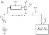
도 8은 이 실시예의 전기살균 필터를 이용한 밸러스트 수처리 시스템의 개략도이다. 도 8에 도시된 바와 같이, 이 실시예의 밸러스트 수처리 시스템(800)은 상기와 같이 구성된 전기살균 필터(100)를 이용한 직접살균 방법과, 간접 살균기에 의한 간접살균 방법을 동시에 적용하도록 구성된다. 즉, 이 실시예의 밸러스트 수처리 시스템(800)은 해수를 펌핑하여 공급하는 해수 공급 펌프(810)와, 해수 저장용 선박평형수 탱크(840) 등의 기존 시스템에 상기와 같이 구성된 전기살균 필터(100), 간접 살균기(820) 및 수소 분리기(830)를 더 구비하여 구성된다.8 is a schematic view of a ballast water treatment system using the electric sterilizing filter of this embodiment. As shown in FIG. 8, the ballast
여기서, 전기살균 필터(100)는 간접 살균기(820)의 전단에 위치하여 50㎛ 이상의 플랑크톤을 흡착하여 살균 제거하고, 간접 살균기(820)는 해수 성분인 소금을 전기분해하여 차아염소산을 1000ppm 이상의 농도로 제조하여 밸러스트 메인라인에 공급한다. 이와 같이 구성된 이 실시예의 밸러스트 수처리 시스템(800)은 밸러스트 메인 스트림의 염소 농도를 5ppm 이하로 유지할 수 있어, 기존의 간접 살균기(820)로 단독 처리하는 경우(밸러스트 메인 스트림의 염소 농도를 20ppm 염소 농도 유지) 보다 낮게 농도를 유지할 수 있어, 유기물과의 반응에 의한 부산물이 적어지고, 에너지 소비량 또한 75% 저감할 수 있다.Here, the
한편, 이 실시예의 밸러스트 수처리 시스템(800)은 밸러스트 메인 스트림의 반대방향으로 유체의 흐름을 주는 소형 역세정용 펌프 및 밸브와 이를 제어하는 컨트롤 장치를 더 구비하여, 역세척을 통해 전기살균 필터(100) 내 전극의 기공성을 복원할 수도 있다.Meanwhile, the ballast
도 9는 이 실시예의 전기살균 필터를 이용한 다른 밸러스트 수처리 시스템의 개략도이다. 도 9에 도시된 바와 같이, 이 실시예의 밸러스트 수처리 시스템(900)은 전기살균 필터(100)가 간접 살균기(920)의 후단에 설치되는 것을 제외하고는 도 8의 밸러스트 수처리 시스템(800)과 동일하게 구성된다. 즉, 이 실시예의 밸러스트 수처리시스템(900)은 해수를 펌핑하여 공급하는 해수 공급 펌프(910)와, 해수 저장용 선박평형수 탱크(940) 등의 기존시스템에 전기살균 필터(100), 간접 살균기(920) 및 수소 분리기(930)를 더 구비하여 구성된다.9 is a schematic view of another ballast water treatment system using the electric sterilizing filter of this embodiment. 9, the ballast
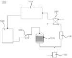
도 10은 이 실시예의 전기살균 필터를 이용한 수영장 수처리 시스템의 개략도이다. 도 10에 도시된 바와 같이, 이 실시예의 수영장 수처리 시스템(1000)은 상기와 같이 구성된 전기살균 필터(100)를 이용하여 수영장의 물을 처리하도록 구성된다. 즉, 이 실시예의 수영장 수처리 시스템(1000)은 수영장 풀(1010)에 유입되는 오염물과 세균을 순환 과정을 통해 제거하도록 구성된다.10 is a schematic view of a swimming pool water treatment system using the electric sterilizing filter of this embodiment. As shown in FIG. 10, the pool
수영장 수처리 시스템(1000)은 순환수의 유량을 조절하기 위한 중간 탱크인 균형조(1020)와, 균형조(1020) 내의 물을 펌핑하여 순환시키는 순환 펌프(1030)와, 순환 펌프(1030)에 의해 순환되는 물에 포함된 오염물질을 제거하는 여과기(1040)와, 차아염소산 나트륨 액체 염소 주입장치 또는 현장에서 소금물을 전기분해하여 차아염소산 나트륨을 생성하여 여과기(1040)를 거쳐 유동하는 유동라인에 공급하는 살균 장치(1050, 도 10에서는 현장형 차아염소산 나트륨 발생기의 구조임)와, 차아염소산 나트륨이 함유된 물을 전기 살균하는 전기살균 필터(100)와, 전기살균 필터(100)에 의해 전기 살균된 물을 열교환하는 열교환기(1060)로 구성된다.The pool
여기서, 전기살균 필터(100)는 여과기(1040)의 후단에 설치되어 살균 기능 외에 물속에 함유된 유기물 및 무기물을 효과적으로 분해하여 여과기(1040)의 오염물 부하를 낮추어 물의 역세주기를 보다 길게 유지할 수 있어, 수영장의 물 사용량을 감소시켜 물을 가온하는데 필요한 에너지를 절약할 수 있다. 한편, 전기살균 필터(100)는 여과기(1040)에 전단에 설치되어 상기와 동일한 기능을 수행할 수도 있다.Here, the
아래에서는 이 발명을 다양한 실험예에 근거해 설명하겠지만, 이 발명의 실시형태가 이것으로 국한되는 것은 아니다.Hereinafter, the present invention will be described on the basis of various experimental examples, but the embodiments of the present invention are not limited thereto.
[실험예 1][Experimental Example 1]
실험예 1은 3차원 다공성 단극 전극체(140)을 이용하여 미생물의 전기살균을 수행한 예이다.Experimental Example 1 is an example of performing the sterilization of microorganisms using the three-dimensional porous
가. 전기살균 필터 및 이를 이용한 수처리 시스템(도 1 및 도 6 참조)end. An electric sterilizing filter and a water treatment system using the same (see Figs. 1 and 6)
(1) 3차원 다공성 양극 전극(141)(1) Three-dimensional
○ 모재 : 기공율 57.5%, 평균 기공 지름 50㎛±5㎛, 직경 10cm, 두께 0.5mm인 섬유형 티타늄○ Base material: fibrous titanium having a porosity of 57.5%, an average pore diameter of 50 袖 m ± 5 袖 m, a diameter of 10 cm, and a thickness of 0.5 mm
○ 촉매층 : 모재를 산으로 화학세정한 후 팔라듐, 이리듐, 루테늄(무게비로 1 : 0.4 : 0.3)이 포함된 염화물과 알코올이 포함된 용액에 디핑 또는 브러슁한 후 이를 소결하는 방법을 통해 촉매층을 형성하였다. 이 과정을 통해 얻은 전극의 표면 사진은 도 11과 같다.Catalyst layer: The catalyst layer is formed by dipping or brushing the base material with a solution containing chlorides and alcohols containing palladium, iridium, and ruthenium (1: 0.4: 0.3 by weight) after chemical cleaning with acid, and then sintering the solution. Respectively. The surface photograph of the electrode obtained through this process is shown in Fig.
○ 개수 : 1○ Number: 1
(2) 3차원 다공성 음극 전극(142)(2) Three-dimensional
○ 모재 : 기공율 57.5%, 평균 기공 지름 50㎛±5㎛, 직경 10cm, 두께 0.5mm인 섬유형 티타늄으로서 별도의 촉매층 코팅을 실시하지 않고 모재 그대로 사용하되 샌드블라스트 및 산 선처리 등만 수행한 티타늄으로, 이 과정을 통해 얻은 전극의 표면 사진은 도 11과 같다.○ Base material: Fiber type titanium having a porosity of 57.5%, an average pore diameter of 50 μm ± 5 μm, a diameter of 10 cm, and a thickness of 0.5 mm. Titanium which has been used only as a base material without sandblasting and acid pretreatment , And a surface photograph of the electrode obtained through this process is shown in FIG.
○ 개수 : 1○ Number: 1
(3) 급전용 전극(120, 130) : 티타늄 소재의 메쉬 타입 모재에 팔라듐, 이리듐, 루테늄 코팅하여 제작한다. 한편, 급전용 전극(120, 130)과 3차원 다공성 양극 전극(141) 및 3차원 다공성 음극 전극(142)은 스폿 용접(spot welding) 등을 이용하여 연결 부위를 견고히 한다.(3) Power Supply Electrodes (120, 130): Manufactured by coating palladium, iridium, and ruthenium on a mesh type base material made of titanium. On the other hand, the
(4) 수처리 시스템(도 6)의 운전조건(4) Operating conditions of the water treatment system (FIG. 6)
도 6과 같이 시스템을 구성하고, Pseudomonas diminuta을 포함한 물을 제1 저장조(610) 내에 준비하고 대상 처리수를 2L/분의 양으로 공급 펌프(620)를 이용하여 전기살균 필터(100)에 공급하고, 전류를 인가하여 실험을 수행했다. 이때, 주요한 운전인자는 다음과 같다.6, the water containing Pseudomonas diminuta is prepared in the
○ 전류공급 : 전극면적 기준으로 0.1A/cm2정전류 인가○ Current supply: 0.1 A / cm2 constant current based on electrode area
○ 전기살균 필터 통과속도 : 1secPassing speed of electric sterilization filter: 1sec
대상 처리수를 저장하고 있는 제1 저장조(610)와 전기 살균된 처리수를 보관하고 있는 제2 저장조(630)에서 물을 각각 채수하여 생균수를 측정했다.Water was collected from the
나. 분석 방법I. Analysis method
(1) 미생물 측정방법(1) Method for measuring microorganisms
측정방법은 한천 배지(에이켄 화학제)를 이용한 한천 평판법을 이용하였다. Pseudomonas diminuta를 액체 배양지를 이용해 1일간 배양한 후, 균체를 5,000rpm으로 원심분리한 후, 순수로 세정하고 재차 원심분리했다. 이를 수돗물 및 증류수(잔류 염소 농도가 0.01ppm 이하)에 첨가하여 대상 처리수로 했다.The agar plate method using agar medium (manufactured by Eiken Chemical Co., Ltd.) was used for the measurement. Pseudomonas diminuta was cultured in a liquid culture medium for 1 day. The cells were centrifuged at 5,000 rpm, washed with pure water, and centrifuged again. This was added to tap water and distilled water (the residual chlorine concentration was 0.01 ppm or less) to obtain treated water.
(2) 염소분석방법(2) Chlorine analysis method
잔류염소는 standard method 4500 Cl-B method I 법으로 측정하고, 염도는 Hach Chlorine meter Ⅱ로 측정하였다.Residual chlorine was measured by standard method 4500 Cl-B method I and salinity was measured by Hach Chlorine meter Ⅱ.
다. 결과All. result
측정결과를 표 1에 나타냈다. 표 1로부터 이 실험예의 3차원 다공성 단극 전극체를 이용한 시스템에서 분명하게 제균 효율이 뛰어난 것으로 판명되었다.The measurement results are shown in Table 1. From Table 1, it was proved that the system using the three-dimensional porous unipolar electrode body of this experimental example clearly showed excellent efficiency of sterilization.
[실험예 2][Experimental Example 2]
실험예 1과 동일한 구성 및 실험조건에서 인가전류(전압)를 펄스형으로 공급하여 제균 성능을 비교했다.The applied current (voltage) was supplied in pulse form under the same constitution and experimental conditions as Experimental Example 1 to compare the sterilization performance.
가. 전기살균 필터 및 이를 이용한 수처리 시스템(도 1 및 도 6 참조)end. An electric sterilizing filter and a water treatment system using the same (see Figs. 1 and 6)
(1) 3차원 다공성 단극 전극체(140) : 실험예 1과 동일(1) Three-dimensional porous unipolar electrode member 140: Same as Experimental Example 1
(2) 급전용 전극(120, 130) : 실험예 1과 동일(2)
(3) 수처리 시스템(도 6)의 운전조건(3) Operation conditions of the water treatment system (FIG. 6)
실험예 1과 동일하며, 전류인가 조건을 달리 하였다.It is the same as Experimental Example 1, and current application conditions are different.
○ 전류공급 : 전극면적 기준으로 0.1A/cm2정전류로 펄스 인가(정방향 30분, 역방향 30분)○ Current supply: Pulse with constant current of 0.1 A / cm2 based on electrode area (30 minutes in the forward direction and 30 minutes in the reverse direction)
나. 분석 방법 : 실험예 1과 동일I. Analytical Method: Same as Experimental Example 1
다. 결과All. result
실험결과를 표 1에 나타냈다. 표 1로부터 이 실시예의 3차원 다공성 단극 전극체를 이용한 시스템이 분명하게 제균 효율이 뛰어난 것으로 판명되었다.The experimental results are shown in Table 1. From Table 1, it was proved that the system using the three-dimensional porous unipolar electrode body of this example was clearly excellent in the efficiency of the eradication.
Average voltage
(Wh)Power consumption
(Wh)
(CFU/ml)Early bacteria
(CFU / ml)
(CFU/ml)End common bacteria
(CFU / ml)
(mg/L)Residual chlorine
(mg / L)
[실험예 1과 실험예 2의 비교][Comparison between Experimental Example 1 and Experimental Example 2]
표 1에서 알 수 있듯이, 실험예 1, 2와 같이 이 실시예의 3차원 다공성 단극 전극체(140)을 이용한 전기살균 필터(100)와 실험예 2의 펄스형 전기인가를 이용하는 전기살균 필터 공정이 제균효율이 뛰어나며, 특히 저전력으로도 제균 효율이 뛰어난 것으로 판명되었다.As can be seen from Table 1, the
[실험예 3][Experimental Example 3]
실험예 3은 밸러스트 수처리 공정에 이 실시예의 3차원 다공성 단극 전극체(140)의 적용 가능성을 파악하기 위하여 50㎛ 이상 크기의 미생물을 전기 살균한 예이다. 실제 밸러스트 수처리 공정은 도 8 및 도 9와 같으나 50㎛ 이상 크기의 미생물을 제거할 목적으로 하는 전기살균 필터만의 효과를 살피기 위하여 도 6과 같이 구성하여 평가하였다.Experimental Example 3 is an example of sterilizing microorganisms having a size of 50 탆 or more in order to understand the applicability of the three-dimensional porous
가. 전기살균 필터 및 이를 이용한 수처리 시스템(도 1 및 도 6 참조)end. An electric sterilizing filter and a water treatment system using the same (see Figs. 1 and 6)
(1) 3차원 다공성 단극 전극체(140) : 실험예 1과 동일(1) Three-dimensional porous unipolar electrode member 140: Same as Experimental Example 1
(2) 급전용 전극(120, 130) : 실험예 1과 동일(2)
(3) 대상미생물 : Artemia salina(이하 A. salina로 기술함)(3) Target microorganism: Artemia salina (hereinafter referred to as A. salina)
Artemia salina는 탈수된 낭종(cysts) 형태로 구입하여 4℃의 암실에서 보관하였다. 사용을 위한 부화시에는 낭종 25mL를 1L의 인공해수에 넣어 28℃에서 유지하면서 공기로 지속적인 에어레이션(aeration)을 하였다.Artemia salina was purchased as dehydrated cysts and stored in a dark room at 4 ° C. At the time of hatching for use, 25 mL of the cyst was placed in 1 L of artificial seawater and maintained at 28 ° C, followed by continuous aeration with air.
Artemia salina의 부화는 24시간 후 완료되었다. 그 후 부화된 Artemia salina를 대상 처리수로 사용되는 200L의 인공해수에 첨가하여 사용하였으며, 또한 에어레이션(aeration)을 지속적으로 수행하였다.The hatching of Artemia salina was completed after 24 hours. Then, the hatched Artemia salina was added to 200 L artificial seawater used as the target treatment water, and the aeration was continuously performed.
나. 시스템의 구성 및 운전I. System configuration and operation
도 6과 같이 시스템을 구성하고, 최종농도 30‰ 염도를 갖는 인공염수는 수돗물에 정제되지 않은 소금을 첨가하여 약 30gpl인 인공해수를 제조하였다. 이렇게 제조된 인공염수에 A. salina를 첨가하여 제1 저장조(610)에서 보관하고 있다가, 대상 처리수를 공급 펌프(620)를 이용하여 4개의 다른 유량조건 50L/h(체류시간 기준 65.5sec), 100L/h(체류시간 기준 32.8sec), 20L/h(체류시간 기준 16.4sec), 그리고 300L/h(체류시간 기준 10.9sec)로 전기살균 필터(100)에 공급하고, 전압을 각각의 유량조건에서 0 ~ 20V 범위(전류값 0 ~ 47A 상당)에서 공급하였다.The system was constructed as shown in FIG. 6, and artificial salt water having a final concentration of 30 ‰ salt was prepared by adding unrefined salt to tap water to about 30 gpl of artificial sea water. A. salina was added to the artificial saline water thus prepared and stored in the
연속적으로 운전하면서 살균 처리된 인공해수의 샘플은 전기 살균된 인공해수가 저장되어 있는 제2 저장조(630)에서 채수하여 생균수를 측정했다. 즉, 제2 저장조(630) 내의 물을 500mL씩 2개의 샘플 비이커에 수집한 후, 한 비이커에는 샘플채수 즉시 전기분해 과정에서 생성된 자유염소를 분해하기 위하여 2mL의 소디움치오설페이트 용액(1N)을 첨가하고, 다른 비이커에는 소디움치오설페이트 용액을 첨가하지 않았다. 1차 샘플은 생존한 A. salina 미생물을 측정하는데 이용하고, 다른 2차 샘플은 총잔류 염소(total residual chlorine) 측정에 이용하였다. 주어진 유량과 전류조건에서 샘플링은 3회 반복하였다.Samples of the artificial seawater sterilized during continuous operation were collected in a
다. 분석방법All. Analysis method
(1) 미생물 분석(1) Microbial analysis
전기분해 전과 전기분해 후의 A. salina의 샘플링 및 측정을 3회 반복하였다. A. salina의 측정에 사용된 각 샘플의 부피는 5mL다. 각 샘플들은 페트리접시(Petri dishes, 직경 90mm)에 옮겨 콜리노 카운터 장치(colony counter apparatus)를 이용하여 측정하였다. 생존 유무의 판단은 생물의 움직임 여부로 판단하였다. A.salina 개수는 l리터 당 생물의 수로 표현하였다.Sampling and measurement of A. salina before and after electrolysis were repeated three times. A. The volume of each sample used in the measurement of the salina is 5 mL. Each sample was transferred to Petri dishes (
라. 결과la. result
도 12는 체류시간과 전류밀도와 A. salina의 사멸율의 관계를 나타낸 그래프이다. 도 12에 나타난 바와 같이, 체류시간과 전류밀도가 높을수록, A. salina의 사멸율이 커졌다. 한편, 65.5sec 체류시간과 전류밀도 135mA/cm2 조건에서 A. salina는 완전히 사멸되었다. 도 12에서 알 수 있듯이, 전기살균 처리공정은 그 체류시간이 비록 1분과 같이 매우 짧더라도 매우 효과적인 공정임을 알 수 있다.12 is a graph showing the relationship between the residence time and current density and the mortality rate of A. salina. As shown in FIG. 12, the higher the residence time and the current density, the greater the death rate of A. salina. On the other hand, A. salina was completely killed at a residence time of 65.5 sec and a current density of 135 mA / cm2 . As can be seen in FIG. 12, it can be seen that the electroerosion treatment process is a very effective process even though the residence time is very short, such as 1 minute.
[비교예 1][Comparative Example 1]
가. 실험방법end. Experimental Method
비교예 1은 시장에서 유통되고 있는 불활성화 제제로 차아염소산의 Artemia salina에 대한 영향을 파악하기 위한 실험으로 500mL 원뿔형 플라스크에서 수행하였다. 인공해수에 차아염소산 화학약품을 첨가한 후에 부화된 Artemia salina를 첨가했다. 이때, 잔류 염소농도는 50, 100 및 200mg/L 수준으로 조절하였다. 샘플은 5, 10, 15, 30 그리고 45분이 경과한 상태에서 살아 있는 Artemia salina를 측정하였다.Comparative Example 1 was carried out in a 500 mL conical flask to investigate the effect of hypochlorous acid on Artemia salina as an inactivated preparation distributed in the market. After addition of hypochlorous acid chemicals to artificial seawater, hatching Artemia salina was added. At this time, the concentration of residual chlorine was adjusted to 50, 100 and 200 mg / L. Samples were taken at 5, 10, 15, 30, and 45 minutes, and live Artemia salina was measured.
나. 결과I. result
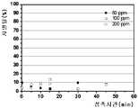
A. salina 사멸에 대한 차아염소산 나트륨(자유잔류염소, free residual chlorine)의 영향을 도 13에 나타냈다. 잔류염소 수준은 50, 100, 200mg/L로 하고, 염소 접촉시간은 0 에서 45분으로 하였다. 일반적으로 A. salina의 사멸은 염소 도징(chlorine dose) 농도와 접촉시간이 클수록 컸다. 가장 큰 A. salina 사멸율(75% 이상)은 고농도의 염소농도(200mg/L)와 15분 이상의 접촉시간에서 얻을 수 있었다.The effect of sodium hypochlorite (free residual chlorine) on A. salina death is shown in FIG. The residual chlorine levels were 50, 100 and 200 mg / L, and the chlorine contact time was 0 to 45 minutes. In general, the death of A. salina was greater with increasing concentrations of chlorine dose and contact time. The highest A. salina kill rate (> 75%) was obtained at high concentration of chlorine (200 mg / L) and contact time of more than 15 minutes.
[비교예 2][Comparative Example 2]
가. 실험방법end. Experimental Method
비교예 2에서는 Artemia salina 증식에 대한 잔류염소와 소듐치오설페이트의 영향을 파악하는 실험을 수행하였다.In Comparative Example 2, experiments were conducted to determine the effect of residual chlorine and sodium thiosulfate on Artemia salina proliferation.
1N 소듐치오설페이트 용액(sodium thiosulfate solution, Na2S2O3·5H2O) 2mL를 원뿔형 플라스크에 첨가한다. 이 양은 200mg/L 잔류염소(residual chlorine)를 제거하는데 충분한 양이다.It is added 1N sodium Fuck sulfate solution(sodium thiosulfate solution, Na 2 S 2 O 3 · 5H 2 O) 2mL a conical flask. This amount is sufficient to remove 200 mg / L residual chlorine.
나. 결과I. result
도 14는 소듐치오설페이트로 염소를 중화시켰을 때의 A. salina 사멸율을 나타낸 것이다. 도 14에 나타난 바와 같이, 임의의 염소 도징 조건과 접촉시간 조건에서도 A. salina 사멸율이 14%를 넘지 않는다. 이는 샘플의 탈염소화 과정에 의해 A. salina의 사멸율이 감소되는 것을 의미한다.14 shows the rate of death of A. salina when neutralizing chlorine with sodium thiosulfate. As shown in Figure 14, the rate of death of the A. salina does not exceed 14% under any chlorine dosing conditions and contact time conditions. This means that the death rate of A. salina is reduced by the dechlorination process of the sample.
[실험예 3과 비교예 1, 비교예 2의 비교 검토][Comparative examination of Experimental Example 3, Comparative Example 1, and Comparative Example 2]
전기분해 과정에서 잔류염소의 농도 수준을 비교하면, 매우 짧은 체류시간에서 고농도를 얻는다. 예를 들면, 135mA/cm2, 체류시간 66.5초에서 염소수준은 475mg/L이며, 동일한 염소농도를 기준으로 하는 전기화학적 처리는 차아염소산 나트륨보다 효과적이다. 한편, A. salina 사멸은 차아염소산 나트륨을 이용하는 경우보다 전기화학적 처리에서 더욱 크다. 이는 불활성화 메커니즘이 양극 표면에서의 직접산화 뿐만 아니라 전극에서 발생하는 차아염소산과의 결합 효과에 의한 것임을 의미한다.Comparing the concentration levels of residual chlorine in the electrolysis process, high concentrations are obtained at very short residence times. For example, the chlorine level is 475 mg / L at 135 mA / cm2 and the residence time is 66.5 seconds, and the electrochemical treatment based on the same chlorine concentration is more effective than sodium hypochlorite. On the other hand, the death of A. salina is larger in the electrochemical treatment than in the case of using sodium hypochlorite. This means that the deactivation mechanism is due to the effect of not only direct oxidation at the anode surface but also bonding effect with hypochlorous acid generated in the electrode.
상기와 같은 결과로부터 얻는 결론은 다음과 같다.The conclusion obtained from the above results is as follows.
첫째, 차아염소산 나트륨은 효과적인 살균제이지만, 200mg/L의 고농도 염소 농도, 접촉시간 1.5min 이상에서는 사멸율이 75% 수준이다. 둘째, 전기화학적 처리는 높은 사멸율을 제공한다. 즉, 전류밀도 135mA/cm2과 1분 정도의 체류시간에서도 A.salina를 100% 수준으로 사멸시킨다. 이 조건에서 잔류염소의 농도는 약 400mg/L이다. 셋째, 전기소모량은 0.07 ~ 19.2kWh/m3 수준이다. 따라서, 최적의 처리조건은 전류밀도 135mA/cm2, 체류시간 65.5sec이고, A. salina 사멸율 100%에서 전기소모량은 3.6kWh/m3 이다.First, sodium hypochlorite is an effective disinfectant, but at a high concentration of chlorine of 200mg / L and a contact time of 1.5min or more, the mortality rate is 75%. Second, electrochemical treatment provides a high mortality rate. That is, at a current density of 135 mA / cm2 and a residence time of about 1 minute, A.salina is killed at 100% level. The concentration of residual chlorine in this condition is about 400 mg / L. Third, the electricity consumption is 0.07 ~ 19.2kWh / m3 . Therefore, the optimal treatment conditions are a current density of 135 mA / cm2 , a residence time of 65.5 sec, and an electricity consumption of 3.6 kWh / m3 at a kill rate of 100% of the salina.
[실험예 4][Experimental Example 4]
실험예 4에서는 일반 수처리 공정에 이 실시예의 3차원 다공성 단극 전극체(140)의 적용 가능성을 파악하였다.In Experimental Example 4, the applicability of the three-dimensional porous
가. 3차원 다공성 단극 전극체(140) 제조 : 실험예 1과 동일end. Production of a three-dimensional porous unipolar electrode member (140): Same as Experimental Example 1
나. 전기분해용 실험장치I. Experimental equipment for electrolysis
돈사 폐수 500ml를 비이커에 넣고, 3차원 다공성 단극 전극체(140)을 설치하여, 회분식 방법(Batch)으로 0.2A/cm2의 운전조건에서 40분간 실시하였다. 실험에 사용한 돈사 폐수의 성상은 표 3의 시간 0에서의 값이다.500 ml of the pesticide wastewater was placed in a beaker, and a three-dimensional porous
다. 분석방법All. Analysis method
원수 및 처리수의 물리화학적 특성분석은 색도의 경우 흡광도법을 적용하고, 암모니아성질소(NH3-N)는 Salicylate method를 적용하였으며, 전기화학 반응에서의 전해 전압은 멀티미터를 적용하고, 염소 발생 효율은 간접 요오드 적정법을 적용하였다.The physicochemical characteristics of raw water and treated water were analyzed by the absorbance method for chromaticity and the salicylate method for ammonia nitrogen (NH3 -N). The electrolytic voltage in the electrochemical reaction was measured using a multimeter and chlorine Indirect iodine titration method was applied to the generation efficiency.
라. 결과la. result
실험 결과는 표 3에 나타냈다. 표 3와 같이 시간에 따라 3차원 다공성 단극 전극체(140)을 사용하였을 때 색도가 쉽게 제거되었다.The experimental results are shown in Table 3. As shown in Table 3, the chromaticity was easily removed when the three-dimensional porous
[비교예 3][Comparative Example 3]
기존의 2차원 평판 전극(DSA 전극)을 이용하여 동일크기, 동일 전류밀도 조건에서 표 3의 돈사 폐수의 색도를 제거하였다. 이때, 실험예 1에서 적용한 것과 동일하게 전극 촉매 로딩, 실험장치, 분석방법을 적용하였다.Using the conventional two-dimensional flat electrode (DSA electrode), the chromaticity of the waste water of the trash tank of Table 3 was removed under the same size and the same current density condition. At this time, the electrode catalyst loading, the experimental apparatus, and the analysis method were applied in the same manner as in Experimental Example 1.
일반 티타늄 플레이트 모재Comparative Example 3
General Titanium Plate Base Material
3차원 다공성 단극 전극체Experimental Example 4
A three-dimensional porous unipolar electrode body
[실험예 4와 비교예 3의 비교 결과][Comparison results of Experimental Example 4 and Comparative Example 3]
표 3에서 알 수 있듯이, 실험예 4의 3차원 다공성 단극 전극체(140)을 사용하였을 때 시간에 따라 색도 및 암모니아가 쉽게 제거되는 반면, 비교예 3의 기존 평판 전극은 암모니아는 제거되지만 색도가 증가되는 것을 확인할 수 있다. 색도와 관련된 이와 같은 원인은, 평판 전극의 경우에는 색과 관련한 유기체와 전기화학 반응에서 발생한 염소와의 반응에 의해 색도가 증가하는 부산물이 형성되는 것에 반하여, 3차원 다공성 단극 전극체(140)의 경우에는 색과 관련한 유기체가 3차원 다공성 단극 전극체(140)에 흡착 분해되는 양이 염소와의 반응에 참여한 양보다 커서 색도의 감소가 이루어지는 것으로 추정된다.As can be seen from Table 3, when the three-dimensional porous
[실험예 5] (소금이 첨가된 전해질의 전기분해)[Experimental Example 5] (Electrolysis of electrolyte containing salt)
실험예 5에서는 전해질 소금물 1%를 가지는 폐수에 이 실시예의 3차원 다공성 단극 전극체(140)의 적용 가능성을 확인하였다.In Experimental Example 5, applicability of the three-dimensional porous
가. 3차원 다공성 단극 전극체(140) 제조 : 실험예 1과 동일end. Production of a three-dimensional porous unipolar electrode member (140): Same as Experimental Example 1
나. 전기분해용 실험장치I. Experimental equipment for electrolysis
돈사 폐수 500ml와 소금물 농도로 1%가 되도록 소금을 비이커에 넣고, 3차원 다공성 단극 전극체(140)을 전기살균 필터 내부에 설치하였다. 회분식 방법(Batch)으로 테스트를 진행하였고 이때 전류밀도는 0.2A/cm2의 운전조건에서 40분간 실시하였다. 실험에 사용한 돈사 폐수의 성분은 표 4의 시간 0에서의 값이다.Salt was placed in a beaker so that the concentration of the pesticide wastewater was 500 ml and the concentration of salt water was 1%, and the three-dimensional porous
다. 분석방법 : 실험예 4와 동일All. Analytical Method: Same as Experimental Example 4
라. 결과la. result
실험 결과는 표 4에 나타냈다. 표 4과 같이 시간이 경과함에 따라 3차원 다공성 단극 전극체(140)을 사용하였을 때 색도가 쉽게 제거되었다.The experimental results are shown in Table 4. As shown in Table 4, the chromaticity was easily removed when the three-dimensional porous
[비교예 4][Comparative Example 4]
비교예 4에서는 비교예 3의 조건에서 전해질에 소금 농도가 1% 되게 돈사 폐수에 소금을 첨가하여, 동일한 전류밀도, 전극 촉매 로딩, 실험장치 및 분석방법을 적용하였다. 실험결과는 표 4에 나타냈다.In Comparative Example 4, the same current density, electrode catalyst loading, experimental apparatus, and analytical method were applied to the electrolytic solution with the salt concentration of 1% under the conditions of Comparative Example 3, and salt was added to the waste water. The experimental results are shown in Table 4.
일반 티타늄 플레이트 모재Comparative Example 4
General Titanium Plate Base Material
3차원 다공성 단극 전극체Experimental Example 5
A three-dimensional porous unipolar electrode body
[실험예 4, 실험예 5와 비교예 3, 비교예 4의 비교 결과][Comparison results of Experimental Example 4, Experimental Example 5, Comparative Example 3, and Comparative Example 4]
표 3, 표 4에서 알 수 있듯이, 실험예 4, 실험예 5의 3차원 다공성 단극 전극체(140)가 비교예 3, 비교예 4의 기존의 평판 전극 보다 시간 경과에 따른 색도 제거율이 컸다. 실험예 4와 실시예 5에 의하면 전해질 첨가에 의해 색도 및 암모니아 제거율이 증가됨을 알 수 있다.As can be seen from Tables 3 and 4, the three-dimensional porous
이상에서 이 발명의 3차원 다공성 단극 전극체를 구비한 전기살균 필터 및 이를 이용한 수처리 방법에 대한 기술사항을 첨부도면과 함께 서술하였지만 이는 이 발명의 가장 양호한 실시예를 예시적으로 설명한 것이다. 따라서, 이 발명이 상기에 기재된 실시예에 한정되는 것은 아니고, 이 발명의 사상 및 범위를 벗어나지 않고 다양하게 수정 및 변형할 수 있음은 이 기술분야에서 통상의 지식을 가진 자에게 자명하므로, 그러한 변형예 또는 수정예들 또한 이 발명의 특허청구범위에 속한다 할 것이다.Although the present invention has been described with reference to the accompanying drawings, it is to be understood that the invention is not limited to the disclosed embodiments, but, on the contrary, is intended to cover various modifications and equivalent arrangements included within the spirit and scope of the invention. It will be apparent to those skilled in the art that various modifications and variations can be made in the present invention without departing from the spirit and scope of the invention as defined by the appended claims. Examples or modifications will also fall within the scope of the claims of this invention.
100 : 전기살균 필터120, 130 : 급전용 전극
140 : 3차원 다공성 단극 전극체150 : 절연부재
160 : 직류전원 공급기170 : 제1 외부도선
180 : 제2 외부도선100: electric sterilizing
140: three-dimensional porous unipolar electrode body 150: insulating member
160: DC power supply 170: 1st outer conductor
180: second outer conductor
Claims (13)
Translated fromKorean상기 3차원 다공성 단극 전극체는 다수의 기공이 다층 구조로 배열되어 일측과 타측이 서로 연통하는 3차원 구조를 가지며 금속 재질로 구성되는 3차원 다공성 모재를 각각 구비하는 양극 전극 및 음극 전극과, 상기 양극 전극과 음극 전극을 서로 간에 일정 간격으로 지지하는 절연성의 지지부재를 포함하며,
상기 3차원 다공성 모재는 엉켜져 있는 가느다란 금속선을 일정 두께로 압착하여 구성하거나, 다수의 금속분말을 바인더와 혼합하여 일정 형태로 성형한 후 소결하여 구성하며,
상기 양극 전극은 상기 3차원 다공성 모재에 코팅되는 전극 촉매층을 갖도록 구성되어, 통전시에 처리수 내에 함유된 미생물을 흡착하여 전기살균함과 더불어 산화제를 발생시켜 살균이 가능하며,
상기 급전용 직류전원 공급기는 상기 한 쌍의 급전용 전극에 일정 주기로 인가전압의 극성을 반전시키면서 운전하되, 역전압인 제2 인가전압을 정전압인 제1 인가전압보다 낮춰 인가하고 100 내지 200A/cm2보다 낮은 운전 전류밀도로 운전하는 것을 특징으로 하는 전기살균 필터.A pair of power supply electrodes provided at predetermined intervals in the flow pipe, at least one three-dimensional porous unipolar electrode unit arranged in a state connected to the pair of power supply electrodes, And a power supply DC power supply for supplying a DC current to the pair of power supply electrodes via first and second external leads,
The three-dimensional porous unipolar electrode assembly includes a positive electrode and a negative electrode each having a three-dimensional porous base material composed of a metal material having a three-dimensional structure in which a plurality of pores are arranged in a multi-layer structure and one side and the other side communicate with each other, And an insulating supporting member for supporting the anode electrode and the cathode electrode at regular intervals between each other,
The three-dimensional porous preform is formed by pressing a thin metal wire having a tangled bundle to a predetermined thickness, or a plurality of metal powders are mixed with a binder to form a predetermined shape and sintered.
The anode electrode is configured to have an electrode catalyst layer coated on the three-dimensional porous base material, so that microorganisms contained in the treated water can be adsorbed and electrically sterilized in the process,
The power supply DC power supply operates the pair of power supply electrodes while inverting the polarity of the applied voltage at regular intervals, applying a second applied voltage, which is a reverse voltage, lower than a first applied voltage,2 < / RTI > operating current density.
상기 3차원 다공성 모재는 0.1 ~ 60㎛의 기공과, 0.5 ~ 5.0mm의 두께를 갖는 것을 특징으로 하는 전기살균 필터.The method according to claim 1,
Wherein the three-dimensional porous base material has pores of 0.1 to 60 탆 and a thickness of 0.5 to 5.0 mm.
상기 3차원 다공성 모재는 탄소, 니켈, 코발트, 티타늄, 지르코늄, 니오븀, 텅스텐, 하프늄, 하스텔로이, 스테인레스 스틸, 철 또는 이들 중 2개 이상을 포함하는 혼합물, 산화물 또는 합금으로 구성되는 것을 특징으로 하는 전기살균 필터.The method according to claim 1,
Characterized in that the three-dimensional porous base material is composed of carbon, nickel, cobalt, titanium, zirconium, niobium, tungsten, hafnium, Hastelloy, stainless steel, iron or mixtures, oxides or alloys comprising two or more of them Electric sterilization filter.
상기 전극 촉매층은 백금, 팔라듐, 로듐, 이리듐, 루테늄, 오스뮴, 탄소, 금, 탄탈륨, 주석, 인듐, 니켈, 텅스텐, 망간 또는 이들 중 2개 이상을 포함하는 혼합물, 산화물 또는 합금으로 구성되는 것을 특징으로 하는 전기살균 필터.The method according to claim 1,
The electrode catalyst layer is composed of platinum, palladium, rhodium, iridium, ruthenium, osmium, carbon, gold, tantalum, tin, indium, nickel, tungsten, manganese or a mixture, oxide or alloy containing two or more of them Lt; / RTI >
상기 처리수에 전해질을 첨가한 상태에서 상기 전기살균 필터를 통해 살균하는 것을 특징으로 하는 수처리 방법.The method of claim 8,
And sterilizing the treated water through the electric sterilizing filter in a state where an electrolyte is added to the treated water.
상기 해수를 상기 전기살균 필터를 통해 통과시키되, 상기 해수의 통과시에 상기 한 쌍의 급전용 전극에 전류를 인가하여 상기 해수 내에 함유된 미생물을 상기 3차원 다공성 단극 전극체에서 흡착하여 전기살균함과 더불어 산화제를 발생시켜 살균하는 것을 특징으로 하는 밸러스트 수처리 방법.And an indirect sterilizer for electrolyzing the seawater to produce hypochlorous acid at a concentration of 1000 ppm or more, wherein the electrolytic sterilizer further comprises an electrolytic sterilizer for electrolyzing the seawater, As a water treatment method in a configured ballast water treatment system,
The microbes contained in the seawater are adsorbed by the three-dimensional porous unipolar electrode body by applying current to the pair of the power supply electrodes when the seawater is passed through the electrolytic sterilizing filter, And an oxidizing agent is generated and sterilized.
상기 전기살균 필터는 상기 간접 살균기의 전단에 위치하는 것을 특징으로 하는 밸러스트 수처리 방법.The method of claim 11,
Wherein the electric sterilizing filter is located at a front end of the indirect sterilizer.
상기 전기살균 필터는 상기 간접 살균기의 후단에 위치하는 것을 특징으로 하는 밸러스트 수처리 방법.The method of claim 11,
Wherein the electric sterilizing filter is located at a rear end of the indirect sterilizer.
Priority Applications (2)
| Application Number | Priority Date | Filing Date | Title |
|---|---|---|---|
| KR1020160031113AKR101812008B1 (en) | 2016-03-15 | 2016-03-15 | An electrolyzer having a porous 3-dimensional mono-polar electrodes, and water treatment method using the electrolyzer having the porous 3-dimensional mono-polar electrodes |
| US15/074,328US9944544B2 (en) | 2016-03-15 | 2016-03-18 | 3-dimensional porous mono-polar electrode body, electric sterilization filter including 3-dimensional porous mono-polar electrode body, and water treatment method using 3-dimensional porous mono-polar electrode body |
Applications Claiming Priority (1)
| Application Number | Priority Date | Filing Date | Title |
|---|---|---|---|
| KR1020160031113AKR101812008B1 (en) | 2016-03-15 | 2016-03-15 | An electrolyzer having a porous 3-dimensional mono-polar electrodes, and water treatment method using the electrolyzer having the porous 3-dimensional mono-polar electrodes |
Publications (2)
| Publication Number | Publication Date |
|---|---|
| KR20170107642A KR20170107642A (en) | 2017-09-26 |
| KR101812008B1true KR101812008B1 (en) | 2017-12-27 |
Family
ID=59855288
Family Applications (1)
| Application Number | Title | Priority Date | Filing Date |
|---|---|---|---|
| KR1020160031113AExpired - Fee RelatedKR101812008B1 (en) | 2016-03-15 | 2016-03-15 | An electrolyzer having a porous 3-dimensional mono-polar electrodes, and water treatment method using the electrolyzer having the porous 3-dimensional mono-polar electrodes |
Country Status (2)
| Country | Link |
|---|---|
| US (1) | US9944544B2 (en) |
| KR (1) | KR101812008B1 (en) |
Cited By (3)
| Publication number | Priority date | Publication date | Assignee | Title |
|---|---|---|---|---|
| KR101986693B1 (en)* | 2018-12-28 | 2019-06-07 | 케이에스티 주식회사 | Ion removal electrode plate structure using hastelloy titanium coating |
| KR102233675B1 (en)* | 2019-11-13 | 2021-03-29 | 김영욱 | Sink mesh strainer for inhibiting formation of biofilm and method for manufacturing thereof |
| KR20210058725A (en)* | 2019-11-13 | 2021-05-24 | 김영욱 | Apparatus having bio film removing or suppressing function |
Families Citing this family (8)
| Publication number | Priority date | Publication date | Assignee | Title |
|---|---|---|---|---|
| KR102027768B1 (en) | 2017-12-19 | 2019-10-02 | 인천대학교 산학협력단 | Seawater splitting electrode, Method for manufacturing the same, and seawater splitting apparatus |
| US11668017B2 (en)* | 2018-07-30 | 2023-06-06 | Water Star, Inc. | Current reversal tolerant multilayer material, method of making the same, use as an electrode, and use in electrochemical processes |
| CN109354136B (en)* | 2018-12-21 | 2023-07-07 | 清华大学 | Disinfection method and disinfection device based on filtration in porous electrode |
| CN109970160B (en)* | 2019-04-08 | 2023-07-28 | 浙江大学 | Particle electrode electrocatalytic oxidation device and method for treating landfill leachate |
| CN110713233B (en)* | 2019-10-18 | 2022-01-28 | 重庆工商大学 | Pd/MnO2-Ni electrode and preparation method and application thereof |
| KR20230034795A (en)* | 2021-09-03 | 2023-03-10 | 엘지전자 주식회사 | Water treatment apparatus |
| KR102676977B1 (en)* | 2021-12-27 | 2024-06-20 | 고려대학교 산학협력단 | Water treatment apparatus with reduction fuction of membrane fouling |
| KR20230158885A (en)* | 2022-05-12 | 2023-11-21 | 엘지전자 주식회사 | Electric field engineered porous catalyst for electro-chlorination at low-salinity conditions and porous catalyst electrode using same |
Citations (2)
| Publication number | Priority date | Publication date | Assignee | Title |
|---|---|---|---|---|
| JP2008023494A (en)* | 2006-07-25 | 2008-02-07 | Nippon Corrosion Engineering Co Ltd | Seawater electrolyzer |
| KR101220891B1 (en)* | 2010-06-30 | 2013-01-11 | 문상봉 | A porous 3-dimensional bipolar electrode, an electrolyzer having the porous 3-dimensional bipolar electrode, and water treatment method using the electrolyzer having the porous 3-dimensional bipolar electrode |
Family Cites Families (3)
| Publication number | Priority date | Publication date | Assignee | Title |
|---|---|---|---|---|
| US6080290A (en)* | 1997-01-03 | 2000-06-27 | Stuart Energy Systems Corporation | Mono-polar electrochemical system with a double electrode plate |
| US20080198531A1 (en)* | 2007-02-15 | 2008-08-21 | Lih-Ren Shiue | Capacitive deionization system for water treatment |
| US9174859B2 (en)* | 2011-11-24 | 2015-11-03 | Eco Watertech, Inc. | Method for treating waste waters |
- 2016
- 2016-03-15KRKR1020160031113Apatent/KR101812008B1/ennot_activeExpired - Fee Related
- 2016-03-18USUS15/074,328patent/US9944544B2/enactiveActive
Patent Citations (2)
| Publication number | Priority date | Publication date | Assignee | Title |
|---|---|---|---|---|
| JP2008023494A (en)* | 2006-07-25 | 2008-02-07 | Nippon Corrosion Engineering Co Ltd | Seawater electrolyzer |
| KR101220891B1 (en)* | 2010-06-30 | 2013-01-11 | 문상봉 | A porous 3-dimensional bipolar electrode, an electrolyzer having the porous 3-dimensional bipolar electrode, and water treatment method using the electrolyzer having the porous 3-dimensional bipolar electrode |
Cited By (6)
| Publication number | Priority date | Publication date | Assignee | Title |
|---|---|---|---|---|
| KR101986693B1 (en)* | 2018-12-28 | 2019-06-07 | 케이에스티 주식회사 | Ion removal electrode plate structure using hastelloy titanium coating |
| KR102233675B1 (en)* | 2019-11-13 | 2021-03-29 | 김영욱 | Sink mesh strainer for inhibiting formation of biofilm and method for manufacturing thereof |
| WO2021096069A1 (en)* | 2019-11-13 | 2021-05-20 | 김영욱 | Drainage net for suppressing biofilm formation |
| KR20210058725A (en)* | 2019-11-13 | 2021-05-24 | 김영욱 | Apparatus having bio film removing or suppressing function |
| KR102396550B1 (en)* | 2019-11-13 | 2022-05-11 | 김영욱 | Apparatus having bio film removing or suppressing function |
| US11773575B2 (en) | 2019-11-13 | 2023-10-03 | Young Wook Kim | Drainage net for suppressing biofilm formation |
Also Published As
| Publication number | Publication date |
|---|---|
| US20170267552A1 (en) | 2017-09-21 |
| US9944544B2 (en) | 2018-04-17 |
| KR20170107642A (en) | 2017-09-26 |
Similar Documents
| Publication | Publication Date | Title |
|---|---|---|
| KR101812008B1 (en) | An electrolyzer having a porous 3-dimensional mono-polar electrodes, and water treatment method using the electrolyzer having the porous 3-dimensional mono-polar electrodes | |
| KR101220891B1 (en) | A porous 3-dimensional bipolar electrode, an electrolyzer having the porous 3-dimensional bipolar electrode, and water treatment method using the electrolyzer having the porous 3-dimensional bipolar electrode | |
| Ghernaout | Microorganisms’ electrochemical disinfection phenomena | |
| TWI447990B (en) | Method and apparatus for producing ozone water, method for disinfection and method for wastewater or waste fluid treatment | |
| KR100597254B1 (en) | Electrolytic Disinfection Equipment for Ship Ballast Water | |
| KR101015728B1 (en) | Water treatment device | |
| JP5764474B2 (en) | Electrolytic synthesis apparatus, electrolytic treatment apparatus, electrolytic synthesis method, and electrolytic treatment method | |
| JP4261189B2 (en) | High-efficiency electrolysis cell that generates oxidants in solution | |
| WO2007008591A2 (en) | Methods and apparatus for generating oxidizing agents | |
| JPH10151463A (en) | Water treatment method | |
| EP2301894A1 (en) | Sterilization method and sterilization device | |
| JP2004143519A (en) | Water treatment method and water treatment device | |
| US4619745A (en) | Process for the electrochemical decontamination of water polluted by pathogenic germs with peroxide formed in situ | |
| JP3396853B2 (en) | Water production method and obtained water | |
| KR101148145B1 (en) | Device for sterilization and removal of microorganism underwater | |
| KR20170052152A (en) | Appratucps for sterilization of ballast water | |
| JP2002275671A (en) | Method for producing hydrogen peroxide aqueous solution | |
| WO2009128573A1 (en) | Electric disinfection grid using virtual electrodes for treating infected water and water treating system using the same | |
| JP2012152695A (en) | Electrolytic salt water sterilization method and electrolytic salt water sterilization device | |
| JP3056511B2 (en) | Treatment water treatment equipment | |
| JP3014427B2 (en) | Treatment of treated water | |
| JP2002053990A (en) | Method of manufacturing hydrogen peroxide water | |
| CN101896432A (en) | Method for pretreating drinking water | |
| JPH06121985A (en) | Fixed bed type three-dimensional electrode electrolyzer | |
| JPH0929259A (en) | Electrode unit for water treatment |
Legal Events
| Date | Code | Title | Description |
|---|---|---|---|
| A201 | Request for examination | ||
| PA0109 | Patent application | St.27 status event code:A-0-1-A10-A12-nap-PA0109 | |
| PA0201 | Request for examination | St.27 status event code:A-1-2-D10-D11-exm-PA0201 | |
| P11-X000 | Amendment of application requested | St.27 status event code:A-2-2-P10-P11-nap-X000 | |
| P13-X000 | Application amended | St.27 status event code:A-2-2-P10-P13-nap-X000 | |
| D13-X000 | Search requested | St.27 status event code:A-1-2-D10-D13-srh-X000 | |
| D14-X000 | Search report completed | St.27 status event code:A-1-2-D10-D14-srh-X000 | |
| E902 | Notification of reason for refusal | ||
| PE0902 | Notice of grounds for rejection | St.27 status event code:A-1-2-D10-D21-exm-PE0902 | |
| T11-X000 | Administrative time limit extension requested | St.27 status event code:U-3-3-T10-T11-oth-X000 | |
| E13-X000 | Pre-grant limitation requested | St.27 status event code:A-2-3-E10-E13-lim-X000 | |
| P11-X000 | Amendment of application requested | St.27 status event code:A-2-2-P10-P11-nap-X000 | |
| P13-X000 | Application amended | St.27 status event code:A-2-2-P10-P13-nap-X000 | |
| PG1501 | Laying open of application | St.27 status event code:A-1-1-Q10-Q12-nap-PG1501 | |
| PE0701 | Decision of registration | St.27 status event code:A-1-2-D10-D22-exm-PE0701 | |
| GRNT | Written decision to grant | ||
| PR0701 | Registration of establishment | St.27 status event code:A-2-4-F10-F11-exm-PR0701 | |
| PR1002 | Payment of registration fee | St.27 status event code:A-2-2-U10-U11-oth-PR1002 Fee payment year number:1 | |
| PG1601 | Publication of registration | St.27 status event code:A-4-4-Q10-Q13-nap-PG1601 | |
| R18-X000 | Changes to party contact information recorded | St.27 status event code:A-5-5-R10-R18-oth-X000 | |
| R18-X000 | Changes to party contact information recorded | St.27 status event code:A-5-5-R10-R18-oth-X000 | |
| P22-X000 | Classification modified | St.27 status event code:A-4-4-P10-P22-nap-X000 | |
| PR1001 | Payment of annual fee | St.27 status event code:A-4-4-U10-U11-oth-PR1001 Fee payment year number:4 | |
| PR1001 | Payment of annual fee | St.27 status event code:A-4-4-U10-U11-oth-PR1001 Fee payment year number:5 | |
| P22-X000 | Classification modified | St.27 status event code:A-4-4-P10-P22-nap-X000 | |
| PR1001 | Payment of annual fee | St.27 status event code:A-4-4-U10-U11-oth-PR1001 Fee payment year number:6 | |
| PR1001 | Payment of annual fee | St.27 status event code:A-4-4-U10-U11-oth-PR1001 Fee payment year number:7 | |
| PC1903 | Unpaid annual fee | St.27 status event code:A-4-4-U10-U13-oth-PC1903 Not in force date:20241220 Payment event data comment text:Termination Category : DEFAULT_OF_REGISTRATION_FEE | |
| PC1903 | Unpaid annual fee | St.27 status event code:N-4-6-H10-H13-oth-PC1903 Ip right cessation event data comment text:Termination Category : DEFAULT_OF_REGISTRATION_FEE Not in force date:20241220 |