KR101811356B1 - Biopsy driver assembly having a control circuit for conserving battery power - Google Patents
Biopsy driver assembly having a control circuit for conserving battery powerDownload PDFInfo
- Publication number
- KR101811356B1 KR101811356B1KR1020127010992AKR20127010992AKR101811356B1KR 101811356 B1KR101811356 B1KR 101811356B1KR 1020127010992 AKR1020127010992 AKR 1020127010992AKR 20127010992 AKR20127010992 AKR 20127010992AKR 101811356 B1KR101811356 B1KR 101811356B1
- Authority
- KR
- South Korea
- Prior art keywords
- circuit
- assembly
- battery
- motion detector
- power
- Prior art date
- Legal status (The legal status is an assumption and is not a legal conclusion. Google has not performed a legal analysis and makes no representation as to the accuracy of the status listed.)
- Active
Links
- 238000001574biopsyMethods0.000titleclaimsabstractdescription18
- 230000033001locomotionEffects0.000claimsabstractdescription152
- 239000000523sampleSubstances0.000claimsdescription290
- 238000000034methodMethods0.000claimsdescription16
- 241000212384BiforaSpecies0.000claims3
- 230000007246mechanismEffects0.000description37
- 239000012530fluidSubstances0.000description35
- RNOTULNEVWPXCY-UHFFFAOYSA-N2-(4-chloro-2-methylphenoxy)propanoic acid;methyl 5-(2,4-dichlorophenoxy)-2-nitrobenzoate;n-methylmethanamineChemical compoundCNC.OC(=O)C(C)OC1=CC=C(Cl)C=C1C.C1=C([N+]([O-])=O)C(C(=O)OC)=CC(OC=2C(=CC(Cl)=CC=2)Cl)=C1RNOTULNEVWPXCY-UHFFFAOYSA-N0.000description15
- 238000007726management methodMethods0.000description14
- 230000005540biological transmissionEffects0.000description10
- 238000007789sealingMethods0.000description10
- 230000008569processEffects0.000description9
- 238000004891communicationMethods0.000description8
- 238000012544monitoring processMethods0.000description8
- 230000007704transitionEffects0.000description8
- 230000006870functionEffects0.000description7
- 239000011148porous materialSubstances0.000description5
- 238000003780insertionMethods0.000description4
- 230000037431insertionEffects0.000description4
- 230000003993interactionEffects0.000description3
- 238000002955isolationMethods0.000description3
- 230000007257malfunctionEffects0.000description3
- 238000012546transferMethods0.000description3
- 239000008280bloodSubstances0.000description2
- 210000004369bloodAnatomy0.000description2
- 210000000481breastAnatomy0.000description2
- 238000012986modificationMethods0.000description2
- 230000004048modificationEffects0.000description2
- 230000037361pathwayEffects0.000description2
- 238000011084recoveryMethods0.000description2
- 230000009467reductionEffects0.000description2
- 238000013519translationMethods0.000description2
- 230000000007visual effectEffects0.000description2
- 235000014676Phragmites communisNutrition0.000description1
- 230000000712assemblyEffects0.000description1
- 238000000429assemblyMethods0.000description1
- 230000008901benefitEffects0.000description1
- 230000002457bidirectional effectEffects0.000description1
- 230000001588bifunctional effectEffects0.000description1
- 239000012620biological materialSubstances0.000description1
- 229910052797bismuthInorganic materials0.000description1
- JCXGWMGPZLAOME-UHFFFAOYSA-Nbismuth atomChemical compound[Bi]JCXGWMGPZLAOME-UHFFFAOYSA-N0.000description1
- 238000010276constructionMethods0.000description1
- 230000008878couplingEffects0.000description1
- 238000010168coupling processMethods0.000description1
- 238000005859coupling reactionMethods0.000description1
- 238000001514detection methodMethods0.000description1
- 238000010586diagramMethods0.000description1
- 230000000694effectsEffects0.000description1
- 238000003306harvestingMethods0.000description1
- 230000007774longtermEffects0.000description1
- 230000013011matingEffects0.000description1
- 229910052751metalInorganic materials0.000description1
- 239000002184metalSubstances0.000description1
- 239000002245particleSubstances0.000description1
- 239000013618particulate matterSubstances0.000description1
- 230000035515penetrationEffects0.000description1
- 230000002572peristaltic effectEffects0.000description1
- 238000005070samplingMethods0.000description1
- 230000003068static effectEffects0.000description1
- 238000012360testing methodMethods0.000description1
Images


Classifications
- A—HUMAN NECESSITIES
- A61—MEDICAL OR VETERINARY SCIENCE; HYGIENE
- A61B—DIAGNOSIS; SURGERY; IDENTIFICATION
- A61B10/00—Instruments for taking body samples for diagnostic purposes; Other methods or instruments for diagnosis, e.g. for vaccination diagnosis, sex determination or ovulation-period determination; Throat striking implements
- A61B10/02—Instruments for taking cell samples or for biopsy
- A61B10/0233—Pointed or sharp biopsy instruments
- A61B10/0266—Pointed or sharp biopsy instruments means for severing sample
- A61B10/0275—Pointed or sharp biopsy instruments means for severing sample with sample notch, e.g. on the side of inner stylet
- A—HUMAN NECESSITIES
- A61—MEDICAL OR VETERINARY SCIENCE; HYGIENE
- A61B—DIAGNOSIS; SURGERY; IDENTIFICATION
- A61B10/00—Instruments for taking body samples for diagnostic purposes; Other methods or instruments for diagnosis, e.g. for vaccination diagnosis, sex determination or ovulation-period determination; Throat striking implements
- A61B10/02—Instruments for taking cell samples or for biopsy
- A61B10/0233—Pointed or sharp biopsy instruments
- A61B10/0283—Pointed or sharp biopsy instruments with vacuum aspiration, e.g. caused by retractable plunger or by connected syringe
- A—HUMAN NECESSITIES
- A61—MEDICAL OR VETERINARY SCIENCE; HYGIENE
- A61B—DIAGNOSIS; SURGERY; IDENTIFICATION
- A61B10/00—Instruments for taking body samples for diagnostic purposes; Other methods or instruments for diagnosis, e.g. for vaccination diagnosis, sex determination or ovulation-period determination; Throat striking implements
- A61B10/02—Instruments for taking cell samples or for biopsy
- A61B2010/0208—Biopsy devices with actuators, e.g. with triggered spring mechanisms
- A—HUMAN NECESSITIES
- A61—MEDICAL OR VETERINARY SCIENCE; HYGIENE
- A61B—DIAGNOSIS; SURGERY; IDENTIFICATION
- A61B17/00—Surgical instruments, devices or methods
- A61B2017/00367—Details of actuation of instruments, e.g. relations between pushing buttons, or the like, and activation of the tool, working tip, or the like
- A61B2017/00398—Details of actuation of instruments, e.g. relations between pushing buttons, or the like, and activation of the tool, working tip, or the like using powered actuators, e.g. stepper motors, solenoids
- A—HUMAN NECESSITIES
- A61—MEDICAL OR VETERINARY SCIENCE; HYGIENE
- A61B—DIAGNOSIS; SURGERY; IDENTIFICATION
- A61B17/00—Surgical instruments, devices or methods
- A61B2017/0046—Surgical instruments, devices or methods with a releasable handle; with handle and operating part separable
- A61B2017/00473—Distal part, e.g. tip or head
- A—HUMAN NECESSITIES
- A61—MEDICAL OR VETERINARY SCIENCE; HYGIENE
- A61B—DIAGNOSIS; SURGERY; IDENTIFICATION
- A61B17/00—Surgical instruments, devices or methods
- A61B2017/00681—Aspects not otherwise provided for
- A61B2017/00734—Aspects not otherwise provided for battery operated
- A—HUMAN NECESSITIES
- A61—MEDICAL OR VETERINARY SCIENCE; HYGIENE
- A61B—DIAGNOSIS; SURGERY; IDENTIFICATION
- A61B2560/00—Constructional details of operational features of apparatus; Accessories for medical measuring apparatus
- A61B2560/02—Operational features
- A61B2560/0204—Operational features of power management
- A61B2560/0209—Operational features of power management adapted for power saving
Landscapes
- Health & Medical Sciences (AREA)
- Life Sciences & Earth Sciences (AREA)
- General Health & Medical Sciences (AREA)
- Public Health (AREA)
- Biomedical Technology (AREA)
- Heart & Thoracic Surgery (AREA)
- Medical Informatics (AREA)
- Molecular Biology (AREA)
- Surgery (AREA)
- Animal Behavior & Ethology (AREA)
- Pathology (AREA)
- Engineering & Computer Science (AREA)
- Veterinary Medicine (AREA)
- Surgical Instruments (AREA)
- Endoscopes (AREA)
- Measurement Of The Respiration, Hearing Ability, Form, And Blood Characteristics Of Living Organisms (AREA)
- Sampling And Sample Adjustment (AREA)
- Primary Cells (AREA)
- Measuring Pulse, Heart Rate, Blood Pressure Or Blood Flow (AREA)
- Measuring And Recording Apparatus For Diagnosis (AREA)
- Manipulator (AREA)
- Investigating Or Analysing Biological Materials (AREA)
Abstract
Translated fromKoreanDescription
Translated fromKorean본 발명은 바이옵시 장치(biopsy apparatus)에 관한 것으로, 보다 구체적으로는 배터리 절전용 제어회로를 구비한 바이옵시 드라이버 조립체에 관한 것이다.BACKGROUND OF THE INVENTION 1. Field of the Invention The present invention relates to a biopsy apparatus, and more particularly to a bi-optic driver assembly having a battery isolation control circuit.
바이옵시(생체검사 또는 조직검사)가 행해지는 부위의 세포가 암성(cancerous)인지를 판단하는데 도움을 주기 위해 환자에게 바이옵시가 행해질 수 있다. 하나의 유형의 진공 보조식 바이옵시 장치는 진공원(vacuum source)을 구비한 핸드헬드(hand-held) 드라이버 조립체와, 상기 드라이버 조립체에 탈착 가능하게 부착할 수 있게 구성된 1회용 바이옵시 프로브 조립체를 포함한다. 유방조직(breast tissue)을 검사하는데 이용되는 일례의 바이옵시 기법은, 예를 들면 관심 유방조직 부위로부터 하나 이상의 조직 샘플(tissue sample)을 채취하기 위해 상기 부위에 바이옵시 프로브를 삽입하는 것을 포함한다.A biopsy may be done to the patient to help determine if the cell at the site where the biopsy (biopsy or biopsy) is performed is cancerous. One type of vacuum assisted bi-ops device includes a hand-held driver assembly having a vacuum source and a disposable bi-ops probe assembly configured to be detachably attachable to the driver assembly . Exemplary biopsy techniques used to examine breast tissue include, for example, inserting a biopsy probe into the site to collect one or more tissue samples from a breast tissue region of interest .
바이옵시 프로브는 전형적으로, 내강(lumen)을 형성하는 원통형 측벽과, 상기 측벽을 통해서 내강까지 연장되는 말단 단부 가까이에 배치된 측면 샘플 노치(sample notch)를 구비한 바이옵시 캐뉼라(biopsy cannula), 예를 들면 바늘(needle)을 포함한다. 샘플 노치를 선택적으로 개폐할 수 있도록 바이옵시 캐뉼라와 동축으로 절단용 캐뉼라(cutting cannula)가 위치된다. 샘플 노치가 개방될 때 샘플 채취되는 조직을 수용할 수 있도록 내강 및 그에 따라 샘플 노치에 진공이 가해지며, 그리고 나서 조직을 절취하기 위해 절단용 캐뉼라에 의해 샘플 노치가 닫혀지며, 절단된 조직은 진공에 의해 내강으로부터 운반되어 수집된다.A bi-ops probe typically includes a biopsy cannula with a cylindrical side wall defining a lumen and a side sample notch disposed proximate the distal end extending through the sidewall to the lumen, For example, a needle. A cutting cannula is positioned coaxially with the bi-optic cannula to selectively open and close the sample notch. Vacuum is applied to the lumen and thus the sample notch to accommodate the tissue being sampled when the sample notch is open, and then the sample notch is closed by the cutting cannula to cut the tissue, And collected from the lumen.
일례의 이러한 핸드헬드 드라이버 조립체는 배터리에 의해 전력이 공급된다. 이 핸드헬드 드라이버 조립체는 (검사) 절차의 개시(開始)시에 전원이 켜지고 나서는, 절차 내내 전원이 켜진 상태로 유지되며 그리고/또는 사용자가 이 핸드헬드 드라이버 조립체의 전원을 끄기 위해 개입할 때까지 켜진 상태로 유지된다. 이러한 핸드헬드 드라이버 조립체는 장기간에 걸쳐 사용될 수 있기 때문에, 배터리 사용수명을 연장시키고 배터리 전력 부족으로 인한 오작동을 방지하기 위해 소비 전력을 최소한으로 유지하는 것이 중요하다.An example of such a handheld driver assembly is powered by a battery. The handheld driver assembly remains powered on throughout the procedure after power is turned on at the start (start) of the (test) procedure and / or until the user intervenes to power off the handheld driver assembly It remains on. Since such handheld driver assemblies can be used over a long period of time, it is important to keep power consumption to a minimum to prolong battery life and to prevent malfunction due to battery power shortage.
본 발명은 배터리 절전용 제어회로를 구비한 바이옵시 드라이버 조립체를 제공한다. 바이옵시 드라이버 조립체는 바이옵시 프로브 조립체를 장착할 수 있도록 구성된다.The present invention provides a bi-optic driver assembly with a battery isolation control circuit. The bi-ops driver assembly is configured to mount the bi-ops probe assembly.
본 명세서에서 사용되는, 구성요소의 이름 앞에 오는 "제1" 및 "제2"라는 용어, 예를 들면 제1의 전기 드라이브, 제2의 전기 드라이브 등은 유사한 특징을 갖는 상이한 구성요소들을 구분하기 위한 식별 목적으로 사용되며, 달리 명시되지 않는 한 반드시 순서를 나타내고자 하는 것은 아니며, "제1", "제2" 등의 용어는 추가적인 유사한 구성요소를 포함하는 것을 배제하기 위한 것도 또한 아니다.As used herein, the terms " first "and" second "preceding the name of a component, for example a first electric drive, a second electric drive, etc., identify different components having similar characteristics Are used for identification purposes, unless the context clearly dictates otherwise, the terms "first," "second," and the like are not intended to exclude inclusion of additional similar elements.
본 발명은 그 일 형태에 있어서, 바이옵시 프로브 조립체를 장착할 수 있도록 구성된 바이옵시 드라이버 조립체에 대한 것이다. 바이옵시 드라이버 조립체는 바이옵시 드라이버 하우징을 포함한다. 바이옵시 드라이버 하우징에는 전기 조립체(electrical assembly)가 결합된다. 전기 조립체는 바이옵시 프로브 조립체에 구동 가능하게 맞물리도록 구성된 적어도 하나의 전기 드라이브(electrical drive)를 포함한다. 배터리가 바이옵시 드라이버 하우징에 결합된다. 제어회로가 바이옵시 드라이버 하우징에 결합된다. 제어회로는 배터리 및 전기 조립체에 전기 결합된다. 제어회로는 동작 탐지기(motion detector), 타이머 회로, 및 배터리 상주 회로(dwell circuit)를 구비한다. 제어회로는 바이옵시 드라이버 조립체의 마지막으로 탐지된 물리적인 움직임 이후로부터 소정 시간 후에는 동작 탐지기에만 전력을 공급함으로써 배터리를 절전하고 바이옵시 드라이버 조립체의 물리적인 움직임이 탐지되면 배터리로부터 전기 조립체에도 전력을 공급하도록 구성된다.In one aspect, the present invention is directed to a bi-optic driver assembly configured to mount a bi-op probe assembly. The bi-optic driver assembly includes a bi-optic driver housing. The bi-optic driver housing is coupled to an electrical assembly. The electrical assembly includes at least one electrical drive configured to be operatively engaged with the bi-ops probe assembly. The battery is coupled to the bifox driver housing. A control circuit is coupled to the bi-optic driver housing. The control circuit is electrically coupled to the battery and the electrical assembly. The control circuit includes a motion detector, a timer circuit, and a battery dwell circuit. The control circuit will only power the motion detector by supplying power to the motion detector a predetermined time after the last detected physical movement of the bi-optic driver assembly and will also power the electrical assembly from the battery if physical movement of the bi- .
본 발명은 그 다른 형태에 있어서 바이옵시 장치에 대한 것이다. 바이옵시 장치는 바이옵시 프로브 조립체와 바이옵시 드라이버 조립체를 포함한다. 바이옵시 프로브 조립체는 종방향 축에 대해 커터 캐뉼라(cutter cannula)와 동축으로 배치된 샘플 바스켓(sample basket)을 포함한다. 바이옵시 프로브 조립체는 종방향 축에 대한 커터 캐뉼라의 이동을 용이하게 하기 위해 커터 캐뉼라에 결합된 제1의 피동부(driven unit)와, 종방향 축에 대한 샘플 바스켓의 이동을 용이하게 하기 위해 샘플 바스켓에 결합된 제2의 피동부를 구비한다. 바이옵시 드라이버 조립체는 바이옵시 프로브 조립체를 장착할 수 있도록 구성된다. 바이옵시 드라이버 조립체는 바이옵시 드라이버 하우징을 포함한다. 바이옵시 드라이버 하우징에는 전기 조립체가 결합된다. 전기 조립체는 바이옵시 프로브 조립체에 구동 가능하게 맞물리도록 구성된 적어도 하나의 전기 드라이브를 포함한다. 배터리가 바이옵시 드라이버 하우징에 결합된다. 제어회로가 바이옵시 드라이버 하우징에 결합된다. 제어회로는 배터리 및 전기 조립체에 전기 결합된다. 제어회로는 동작 탐지기, 타이머 회로, 및 배터리 상주 회로를 구비한다. 제어회로는 바이옵시 드라이버 조립체의 마지막으로 탐지된 물리적인 움직임 이후로부터 소정 시간 후에는 동작 탐지기에만 전력을 공급함으로써 배터리를 절전하고 바이옵시 드라이버 조립체의 물리적인 움직임이 탐지되면 배터리로부터 전기 조립체에도 전력을 공급하도록 구성된다.The present invention relates to a bi-view device in another form. The bi-optic device includes a bi-op probe assembly and a bi-optic driver assembly. The bi-ops probe assembly includes a sample basket coaxially disposed with a cutter cannula relative to the longitudinal axis. The bi-opaque probe assembly includes a first driven unit coupled to the cutter cannula to facilitate movement of the cutter cannula relative to the longitudinal axis and a second driven unit coupled to the cutter cannula to facilitate movement of the sample basket relative to the longitudinal axis. And a second driven portion coupled to the basket. The bi-ops driver assembly is configured to mount the bi-ops probe assembly. The bi-optic driver assembly includes a bi-optic driver housing. The bi-op-driver housing is coupled to an electrical assembly. The electrical assembly includes at least one electrical drive configured to operatively engage the bi-op-probe assembly. The battery is coupled to the bifox driver housing. A control circuit is coupled to the bi-optic driver housing. The control circuit is electrically coupled to the battery and the electrical assembly. The control circuit includes an operation detector, a timer circuit, and a battery resisting circuit. The control circuit will only power the motion detector by supplying power to the motion detector a predetermined time after the last detected physical movement of the bi-optic driver assembly and will also power the electrical assembly from the battery if physical movement of the bi- .
본 발명은 그 다른 형태에 있어서 바이옵시 프로브 조립체를 장착할 수 있도록 구성된 바이옵시 드라이버 조립체에 대한 것이다. 바이옵시 드라이버 조립체는 바이옵시 드라이버 하우징을 포함한다. 바이옵시 드라이버 하우징에는 전기 조립체가 결합된다. 전기 조립체는 바이옵시 프로브 조립체에 구동 가능하게 맞물리도록 구성된 적어도 하나의 전기 드라이브를 포함한다. 배터리가 바이옵시 드라이버 하우징에 결합된다. 제어회로가 바이옵시 드라이버 하우징에 결합된다. 제어회로는 배터리 및 전기 조립체에 전기 결합된다. 제어회로는 동작 탐지기, 타이머 회로, 및 배터리 상주 회로를 구비한다. 제어회로는 바이옵시 드라이버 조립체의 마지막으로 탐지된 물리적인 움직임 이후로부터 소정 시간 후에는 동작 탐지기에는 전력 공급을 유지하면서 전기 조립체 및 타이머 회로에 대한 전력을 차단함으로써 배터리를 절전하도록 구성되고, 바이옵시 드라이버 조립체의 물리적인 움직임이 탐지되면 배터리로부터 동작 탐지기, 타이머 회로, 및 전기 조립체에 전력을 공급하도록 구성된다.The present invention is in its other aspect a bi-optic driver assembly configured to mount a bi-op probe assembly. The bi-optic driver assembly includes a bi-optic driver housing. The bi-op-driver housing is coupled to an electrical assembly. The electrical assembly includes at least one electrical drive configured to operatively engage the bi-op-probe assembly. The battery is coupled to the bifox driver housing. A control circuit is coupled to the bi-optic driver housing. The control circuit is electrically coupled to the battery and the electrical assembly. The control circuit includes an operation detector, a timer circuit, and a battery resisting circuit. The control circuit is configured to save power by shutting off power to the electrical assembly and the timer circuit while maintaining power supply to the motion detector a predetermined time after the last detected physical movement of the bi-op driver assembly, And to power the motion detector, the timer circuit, and the electrical assembly from the battery when physical movement of the assembly is detected.
본 발명은 그 다른 형태에 있어서 바이옵시 프로브 조립체를 장착할 수 있도록 구성된 바이옵시 드라이버 조립체에 대한 것이다. 바이옵시 드라이버 조립체는 바이옵시 드라이버 하우징과, 상기 바이옵시 드라이버 하우징에 결합된 전기 조립체를 포함한다. 전기 조립체는 바이옵시 프로브 조립체에 구동 가능하게 맞물리도록 구성된 적어도 하나의 전기 드라이브를 포함한다. 제어회로가 바이옵시 드라이버 하우징에 결합된다. 제어회로는 전기 조립체에 전기 결합된다. 제어회로는 동작 탐지기, 타이머 회로, 및 전력 상주 회로를 구비한다. 전력 상주 회로는 전기 조립체에 전기 접속된 전력 출력부를 구비한다. 동작 탐지기와 타이머 회로 각각은 전력 상주 회로로부터의 전력을 수신하도록 전기 접속된다. 동작 탐지기는 타이머 회로 및 전력 상주 회로에 통신 가능하게 결합된다. 동작 탐지기는 전력 상주 회로가 바이옵시 드라이버 조립체의 물리적인 움직임이 탐지될 때 전기 조립체에 전력이 공급되는 동작 모드(operative mode)로 들어가도록 전력 상주 회로에 제1의 신호를 제공하도록 구성되고, 또한 동작 탐지기는 바이옵시 드라이버 조립체의 마지막으로 탐지된 물리적인 움직임을 나타내는 제2의 신호를 타이머 회로에 제공하도록 구성된다. 타이머 회로는 전력 상주 회로에 통신 가능하게 결합된다. 타이머 회로는 전력 상주 회로가 타이머 회로와 전기 조립체를 제외하고 동작 탐지기에 전력이 공급되는 전력 상주 모드로 들어가도록 전력 상주 회로에 제3의 신호를 제공하도록 구성된다. 제3의 신호는 바이옵시 드라이버 조립체의 마지막으로 탐지된 물리적 움직임 이후로부터 소정 시간 후에 전력 상주 회로에 공급된다.The present invention is in its other aspect a bi-optic driver assembly configured to mount a bi-op probe assembly. The bi-ops driver assembly includes a bi-optic driver housing and an electrical assembly coupled to the bi-optic driver housing. The electrical assembly includes at least one electrical drive configured to operatively engage the bi-op-probe assembly. A control circuit is coupled to the bi-optic driver housing. The control circuit is electrically coupled to the electrical assembly. The control circuit includes an operation detector, a timer circuit, and a power resisting circuit. The power resisting circuit includes a power output portion electrically connected to the electrical assembly. Each of the motion detector and the timer circuit is electrically connected to receive power from the power resisting circuit. The motion detector is communicatively coupled to the timer circuit and the power resisting circuit. The motion detector is configured to provide a first signal to the power resisting circuit such that the power resisting circuit enters an operative mode in which power is supplied to the electrical assembly when physical movement of the bi-op driver assembly is detected, The motion detector is configured to provide a timer circuit with a second signal indicative of the last detected physical movement of the bi-op driver assembly. The timer circuit is communicatively coupled to the power resisting circuit. The timer circuit is configured to provide a third signal to the power resisting circuit such that the power resisting circuit enters the power resisting mode in which power is supplied to the motion detector except for the timer circuit and the electrical assembly. The third signal is supplied to the power resisting circuit a predetermined time after the last detected physical movement of the bi-optic driver assembly.
첨부된 도면과 연계되어 취해진 이하의 본 발명의 실시예의 상세한 설명을 참조함으로써, 본 발명의 전술한 특징 및 다른 특징과 이점, 및 이를 달성하는 방식은 보다 분명해질 것이며 본 발명이 보다 잘 이해될 것이다.BRIEF DESCRIPTION OF THE DRAWINGS The foregoing and other features and advantages of the present invention and the manner of achieving it will become more apparent and the invention will be better understood by reference to the following detailed description of an embodiment of the invention taken in conjunction with the accompanying drawings .
해당 참조 문자는 여러 도면에 걸쳐서 해당 부분을 지칭한다. 본 상세한 설명에 개시된 실례는 본 발명의 실시예를 예시하며 이러한 실례는 어떠한 방식으로도 본 발명의 범위를 제한하는 것으로 해석되어서는 안 된다.The reference character refers to that portion throughout the drawings. The examples disclosed in this specification illustrate embodiments of the invention and these examples are not to be construed as limiting the scope of the invention in any way.
따라서, 본 발명의 양태에 따르면, 배터리(34)의 수명을 연장시키고 배터리 전력의 부족으로 인한 바이옵시 장치(10)의 오작동을 방지하는데 일조하도록 소비 전력을 합당한 최소치로 유지하면서, 바이옵시 드라이버 조립체(12)는 바이옵시 프로브 조립체(14)에 장착되어 장기간 바이옵시 프로브 조립체(14)와 함께 작동될 수 있다.Thus, according to aspects of the present invention, while maintaining the power consumption at a reasonable minimum to help extend the life of the
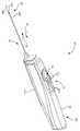
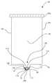
도 1은 1회용 바이옵시 프로브가 바이옵시 드라이버 조립체에 장착된, 본 발명의 일 실시예에 따라 구성된 바이옵시 장치의 사시도.
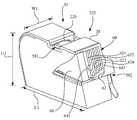
도 2는 1회용 바이옵시 프로브가 드라이버 조립체로부터 분리된, 도 1의 바이옵시 장치의 사시도.
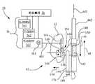
도 3은 도 1의 바이옵시 장치의 개략도.
도 4a는 도 3의 드라이버 조립체의 진공 경로(vacuum path)의 진공 밀봉 요소의 사시도.
도 4b는 도 3의 1회용 바이옵시 프로브의 진공 경로의 진공 밀봉 요소의 사시도.
도 5a는 필터 장치를 노출시키기 위해 일부가 제거된, 도 2 및 도 3에 도시된 1회용 바이옵시 프로브의 유체 관리 탱크의 사시도.
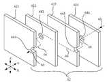
도 5b는 도 5a의 필터 장치의 복수의 유체 흡수층의 분해도.
도 5c는 도 5a의 필터 장치의 세공(細孔) 필터 요소의 사시도.
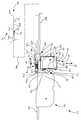
도 6은 샘플 수집 탱크가 제거된 상태로 조직 샘플 회수 메커니즘을 더욱 상세히 도시하는, 도 2의 1회용 바이옵시 프로브의 측면도.
도 7은 샘플 수집 탱크가 설치되고 샘플 수집 탱크가 상승 위치에 있는 상태로, 조직 샘플 회수 메커니즘을 도시하는 도 6의 1회용 바이옵시 프로브의 측면도.
도 8은 샘플 수집 탱크가 설치되고 샘플 수집 탱크가 하강 수집 위치에 있는 상태로, 조직 샘플 회수 메커니즘을 도시하는 도 6의 1회용 바이옵시 프로브의 측면도.
도 9는 샘플 바스켓을 후퇴시키는 것을 노출시키기 위해 커터 캐뉼라의 일부가 절취되고 샘플 노치와 샘플 수집 탱크의 조직 샘플 스쿱(scoop)의 상호작용을 도시하기 위해 샘플 바스켓의 일부가 제거된, 도 8의 조직 샘플 회수 메커니즘의 일부의 측면도.
도 10은 도 9의 10-10 선을 따라 단면도로 도시된, 샘플 바스켓과 샘플 수집 탱크의 림(rim)의 상호작용을 도시하는 도 9의 샘플 수집 탱크의 확대 정면도.
도 11은 도 8의 탱크 위치설정 메커니즘의 평면도.
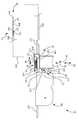
도 12는 T 형상의 멈춤부, 및 샘플 바스켓의 샘플 노치의 진공 경로로부터 잔여 조직 시료 및 잔해를 제거하기 위한 T 형상의 멈춤부의 일부를 형성하는 판스프링 텅(leaf spring tongue)을 노출시키기 위해 리프트 부재(lift member)의 일부가 제거된, 도 7의 1회용 바이옵시 프로브의 리프트 부재 및 샘플 바스켓의 평면도.
도 13은 잠겨진 운반 위치에 있는 탱크 위치설정 메커니즘의 래치 부재를 도시하는 도 7의 1회용 바이옵시 프로브의 측면도.
도 14는 도 1의 바이옵시 드라이버 조립체의 배터리 절전용 회로의 블록도.
도 15는 도 14에 도시된 실시예에 따른 배터리 절전 공정의 순서도.1 is a perspective view of a bi-view device configured in accordance with an embodiment of the present invention, in which a disposable bi-ops probe is mounted on a bi-optic driver assembly;
2 is a perspective view of the bi-optic device of FIG. 1 with the disposable bi-ops probe separated from the driver assembly;
3 is a schematic view of the bi-vision device of FIG.
Figure 4a is a perspective view of a vacuum sealing element of the vacuum path of the driver assembly of Figure 3;
Figure 4b is a perspective view of the vacuum sealing element of the vacuum path of the disposable bi-ops probe of Figure 3;
Figure 5A is a perspective view of the fluid management tank of the disposable bi-ops probe shown in Figures 2 and 3, partially removed to expose the filter device.
Figure 5b is an exploded view of a plurality of fluid absorbing layers of the filter device of Figure 5a.
Figure 5c is a perspective view of the pore filter element of the filter device of figure 5a.
FIG. 6 is a side view of the disposable bi-ops probe of FIG. 2, showing the tissue sample collection mechanism in greater detail with the sample collection tank removed. FIG.
Figure 7 is a side view of the disposable bi-ops probe of Figure 6 showing the tissue sample retrieval mechanism with the sample collection tank installed and the sample collection tank in the raised position;
Figure 8 is a side view of the disposable bi-optic probe of Figure 6 showing the tissue sample retrieval mechanism with the sample collection tank installed and the sample collection tank in the lower collection position;
FIG. 9 is a cross-sectional view of the cutter cannula of FIG. 8, in which a portion of the cutter cannula is cut away to expose retracting the sample basket and a portion of the sample basket is removed to illustrate the interaction of the tissue sample scoop of the sample notch with the sample collection tank. Side view of a portion of the tissue sample recovery mechanism.
Figure 10 is an enlarged front view of the sample collection tank of Figure 9 showing the interaction of the sample basket and the rim of the sample collection tank, shown in cross-section along line 10-10 of Figure 9;
Figure 11 is a plan view of the tank positioning mechanism of Figure 8;
Figure 12 is a side elevational view of a lifting device for exposing a leaf spring tongue forming a portion of a T-shaped stop to remove residual tissue samples and debris from the vacuum path of the sample notch of the T- 7. A top view of a lift member and a sample basket of the disposable bi-ops probe of Fig. 7, wherein a portion of the lift member is removed.
Figure 13 is a side view of the disposable bi-ops probe of Figure 7 showing the latching member of the tank positioning mechanism in the locked transport position;
Figure 14 is a block diagram of a battery isolation circuit of the bi-optic driver assembly of Figure 1;
15 is a flowchart of a battery power saving process according to the embodiment shown in FIG.
이제 도면, 특히 도 1과 도 2를 참조하면, 일반적으로 비침입성의, 예를 들면 비일회용(non-disposable) 바이옵시 드라이버 조립체(12)와 1회용 바이옵시 프로브 조립체(14)를 포함하는 바이옵시 장치(10)가 도시되어 있다.Referring now to the drawings, and more particularly to FIGS. 1 and 2, there is shown a perspective view of a generally bi-disposable, non-disposable
도 3도 또한 참조하면, 드라이버 조립체(12)와 1회용 바이옵시 프로브 조립체(14)는 공동으로, 진공원(18)과, 제1의 진공 경로(20) 및 제2의 진공 경로(22)를 포함하는 유체 관리 시스템(16)을 포함한다. 아래에 보다 구체적으로 설명되는 바와 같이, 안전하고 효과적인 바이옵시 조직 샘플의 수집을 용이하게 하기 위해, 진공원(18)과 제1의 진공 경로(20)는 드라이버 조립체(12)에 영구 결합되고, 제2의 진공 경로(22)는 1회용 바이옵시 프로브 조립체(14)에 영구 결합된다.3 also shows that the
본 명세서에서 사용되는 "비일회용"이라는 용어는 장치의 사용수명 동안에 복수의 환자들에게 사용하기 위한 장치를 지칭하는데 사용되고, "1회용"이라는 용어는 한 명의 환자에게 사용되고 난 후에 폐기되는 장치를 지칭하는데 사용된다. 또한, "진공 경로"라는 용어는 두 지점 사이에 진공을 용이하게 하는데 사용되는 유체 통로를 의미하며, 유체 통로는 예를 들면, 하나 이상의 튜브, 도관, 커플러(coupler), 및 개재(介在)된 장치와 같은 하나 이상의 구성요소를 통과한다. 또한, "영구 결합"이라는 용어는 구성요소의 사용수명 동안에 일상적으로는 탈착 가능하지 않은 접속을 의미한다. 따라서, 예를 들면 진공원(18)과 제1의 진공 경로(20)를 포함하는 드라이버 조립체(12)는 그 전체 유닛이 재사용 가능한 반면, 1회용 바이옵시 프로브 조립체(14)와 제2의 진공 경로(22)는 그 전체 유닛이 폐기될 수 있다.The term " non-disposable "as used herein is used to refer to an apparatus for use with a plurality of patients during the life of the device, and the term " disposable" refers to a device that is discarded after being used by one patient . The term "vacuum path" also refers to a fluid pathway used to facilitate vacuum between two points, the fluid pathway including, for example, one or more tubes, conduits, couplers, and intervening Such as a device. Also, the term "permanent bond" refers to a connection that is not routinely detachable during the life of the component. Thus, for example, the
드라이버 조립체(12)는 사용자에 의해 파지(把持)될 수 있도록 구성되고 인체공학적으로 설계된 하우징(24)을 포함하며, 이 하우징(24)에는 드라이버 조립체(12)의 전기 및 기계적인 구성요소들이 결합 즉, 장착된다. 드라이버 조립체(12)는 (하우징(24) 내에 포함된) 진공원(18), 제1의 진공 경로(20), 컨트롤러(26), 전기기계식 동력원(28), 및 진공 감시 메커니즘(30)을 포함한다. 하우징(24)에 장착될 수 있고 하우징(24)에 대해 외부에서 액세스할 수 있도록 사용자 인터페이스(32)가 배치된다. 하우징(24)에는 드라이버 조립체(12)가 바이옵시 프로브 조립체(14)에 장착될 때 바이옵시 프로브 조립체(14)의 대응하는 하우징(57)을 수용하도록 구성된 세장형 중공부(elongate cavity: 241)가 형성된다.The
컨트롤러(26)는 전기기계식 동력원(28), 진공원(18), 사용자 인터페이스(32), 및 진공 감시 메커니즘(30)에 통신 가능하게 결합된다. 컨트롤러(26)는 예를 들면, 전기기계식 동력원(28)과 진공원(18)의 하나 이상의 구성요소의 제어와 같이, 바이옵시 조직 샘플의 회수와 관련된 기능을 수행하기 위한 프로그램 명령을 실행하기 위해 마이크로프로세서 및 관련 메모리를 포함할 수 있다. 컨트롤러(26)는, 바이옵시 장치(10)의 구성요소들의 하나 이상의 상태 및/또는 위치를 감시하고 드라이버 조립체(12) 및 바이옵시 프로브 조립체(14)와 관련된 유체 관리 시스템(16)의 상태를 감시하기 위해 프로그램 명령을 또한 실행할 수 있다.The controller 26 is communicatively coupled to an
사용자 인터페이스(32)는 제어 버튼(321)과 시각 표시자(visual indicator: 322)를 포함하며, 제어 버튼(321)은 바이옵시 장치(10)의 다양한 기능들에 대한 사용자 제어를 제공하고, 시각 표시자(322)는 바이옵시 장치(10)의 구성요소들의 하나 이상의 상태 및/또는 위치의 상황에 대한 시각적인 피드백을 제공한다.The
전기기계식 동력원(28)은 예를 들면, 전기 에너지원, 예컨대 배터리(34)와 전기 드라이브 조립체(36)를 포함할 수 있다. 배터리(34)는 예를 들면, 재충전 가능한 배터리일 수 있다. 배터리(34)는 바이옵시 장치(10)에 있는 모든 전기 구동 구성요소에 전력을 공급하며, 그래서 도면의 간략함을 위해 이러한 전기적인 커플링은 도시되지 않았다. 예를 들면, 배터리(34)는 진공원(18), 컨트롤러(26), 사용자 인터페이스(32), 및 전기 드라이브 조립체(36)에 전기 결합된다.The
본 실시예에서, 전기 드라이브 조립체(36)는 제1의 드라이브(361)와 제2의 드라이브(362)를 포함하며, 제1 및 제2의 드라이브(361, 362) 각각은 배터리(34)에 결합되고, 제1의 드라이브(361)와 제2의 드라이브(362) 각각은 사용자 인터페이스(32)에 각각 전기적으로 제어 가능하게 결합된다.In this embodiment, the
제1의 드라이브(361)는 전기 모터(381)와 (선으로 개략적으로 도시된) 운동 전달부(motion transfer unit: 401)를 포함할 수 있다. 제2의 드라이브(362)는 전기 모터(382)와 (선으로 개략적으로 도시된) 운동 전달부(402)를 포함할 수 있다. 각 전기 모터(381, 382)는 예를 들면, DC 모터(직류 모터), 스테퍼 모터(stepper motor) 등일 수 있다. 제1의 드라이브(361)의 운동 전달부(401)는 예를 들면, 웜 기어(worm gear) 장치, 랙과 피니언 장치, 솔레노이드 슬라이드(solenoid-slide) 장치 등과 같은 회전-직선 운동 변환기로 구성될 수 있다. 제2의 드라이브(362)의 운동 전달부(402)는 회전 운동을 전달하도록 구성될 수 있다. 제1의 드라이브(361)과 제2의 드라이브(362) 각각은 하나 이상의 기어, 기어 트레인, 벨트/풀리 장치 등을 포함할 수 있다.The
진공원(18)은 배터리(34)에 전기 결합되며, 진공을 형성하기 위한 진공원 포트(181)를 구비한다. 진공원(18)은 사용자 인터페이스(32)에 제어 가능하게 전기 결합된다. 진공원(18)은 예를 들면, 전기 모터(183)에 의해 구동되는 진공 펌프(182)를 더 포함할 수 있다. 진공 펌프(182)는 예를 들면, 연동 펌프(peristaltic pump: 액체이송 펌프), 다이어프램 펌프(diaphragm pump), 주사기형 펌퍼(syringe-type pump) 등일 수 있다.The
드라이버 조립체(12)의 제1의 진공 경로(20)는 진공원(18)과 영구 결부된다. 종종 비일회용 진공 경로라고도 일컬어지는 제1의 진공 경로(20)는 근접 단부(201)와 말단 단부(202)를 구비하며, 예를 들면 도관(203), 제1의 일방향 밸브(204), 및 미립자 필터(particulate filter: 205)를 포함한다. 근접 단부(201)는 유체 유통 상태로 진공원(18)에 고정 결합된다, 예를 들면 진공원(18)의 진공원 포트(181)에 고정 접속된다. 도 4a를 또한 참조하면, 말단 단부(202)는 제1의 진공 밀봉 요소(206)를 포함한다. 본 실시예에서, 제1의 진공 밀봉 요소(206)는 제1의 진공 경로(20)의 제1의 통로(207)를 둘러싸는 평면형 지지 표면이다.The
제1의 일방향 밸브(204)는 진공원(18) 쪽으로의 부압(負壓) 유체 유동은 허용하고 진공원(18)으로부터 제1의 진공 경로(20)의 말단 단부(202) 쪽으로의 정압 유체 유동은 방지하도록 구성 및 배치된다. 제1의 일방향 밸브(204)는 예를 들면, 진공원(18) 쪽으로의 유체 유동에 의해 개방되고 진공원(18)으로부터 멀어지는 쪽으로의 역류(정압 유동)의 경우에 폐쇄되는 볼 밸브(ball valve) 또는 리드 밸브(reed valve)와 같은 체크 밸브일 수 있다.The first one-
본 실시예에서, 미립자 필터(205)는 진공원(18)과 제1의 진공 경로(20)의 말단 단부(202)의 사이에 위치된다. 미립자 필터(205)는 예를 들면, 금속 또는 플라스틱으로 형성된 메시 스크린(mesh screen)일 수 있다. 하지만, 진공원(18)과 바이옵시 프로브 조립체(14)의 진공 수신 요소(vacuum receiving component)의 사이에서 유체 관리 시스템(16)에 미립자 필터(18)가 배치되는 것도 고려될 수 있다.In this embodiment, the
진공 감시 메커니즘(30)은 감지된 진공 수준이 한계치 수준(threshold level) 미만으로 떨어질 때 진공원(18)을 차단하도록 진공원(18)에 결합된다. 진공 감시 메커니즘(30)은 예를 들면, 컨트롤러(26)에서 실행되는 진공 감시 및 제어 프로그램 및 제1의 진공 경로(20)의 압력을 검출하기 위해 제1의 진공 경로(20)와 유체 유통 상태에 있으며 컨트롤러(26)에 결합된 압력 센서(301)를 포함할 수 있다. 예를 들어, 제1의 진공 경로(20)에서의 진공 유동 수준이 소정 수준 미만으로 떨어져서 유체 관리 시스템(16)에 제약상태를 나타내게 되면, 컨트롤러(26)는 진공원(18)을 차단함으로써, 예를 들면 전기 모터(183)의 전원을 끔으로써 이에 응답할 수 있다. 이와 달리, 컨트롤러(26)는 전기 모터(183)에 공급되는 전류를 감시할 수 있으며, 그 전류가 소정량을 초과하여 유체 관리 시스템(16)에 제약상태를 나타내게 되면, 컨트롤러(26)는 진공원(18)을 차단함으로써, 예를 들면 전기 모터(183)의 전원을 끔으로써 이에 대응할 수 있다.The
1회용 바이옵시 프로브 조립체(14)는 드라이버 조립체(12)에 탈착 가능하게 부착되도록 구성된다. 본 명세서에서 사용되는 "탈착 가능하게 부착"이라는 용어는 공구를 사용할 필요없이 의도하는 임시 접속 및 뒤이어지는 드라이버 조립체(12)에 대한 1회용 바이옵시 프로브 조립체(14)의 조작을 통한 선택적인 분리를 용이하게 하는 구성을 의미한다.The disposable
1회용 바이옵시 프로브 조립체(14)는 본질적으로 프레임 기능을 하는 커버(141)를 포함하며, 커버(141)에는 트랜스미션 장치(42), 바이옵시 프로브(44), 하우징(57) 및 제2의 진공 경로(22)가 장착되며, 하우징(57)은 커버(141)에 미끄럼운동 가능하게 결합된다. 커버(141)에 대한 하우징(57)의 미끄럼운동 결합은 예를 들면, 레일 및 U 브래킷 구성에 의해 달성될 수 있다. 커버(141)는 바이옵시 프로브 조립체(14)가 드라이버 조립체(12)에 장착될 때 드라이버 조립체(12)의 내부 구조를 보호하기 위해 드라이버 조립체(12)의 하우징(24)에 있는 세장형 중공부(241)을 폐쇄하기 위해 미끄럼운동 가능한 커버 기능을 한다. 바이옵시 프로브(44)는 트랜스미션 장치(42)에 구동 가능하게 결합되며, 트랜스미션 장치(42)는 바이옵시 프로브 조립체(14)가 드라이버 조립체(12)에 장착될 때 드라이버 조립체(12)의 전기기계식 동력원(28)에 구동 가능하게 결합된다.The disposable
도시된 실시예에서, 트랜스미션 장치(42)는 바이옵시 프로브(44)의 다양한 구성요소와 구동 가능하게 맞물리는 제1의 피동부(421)와 제2의 피동부(422)를 포함한다. 또한, 제1의 피동부(421)는 드라이버 조립체(12)의 전기 드라이브 조립체(36)의 제1의 드라이브(361)와 구동 가능하게 맞물린다. 제2의 피동부(422)는 드라이버 조립체(12)의 전기 드라이브 조립체(36)의 제2의 드라이브(362)와 구동 가능하게 맞물린다. 제1의 피동부(421)는 하우징(57)에 미끄럼운동 가능하게 결합되고, 제2의 피동부(422)는 하우징(57) 내에 포함된다. 제1의 피동부(421)(예컨대, 미끄럼운동 부재)의 미끄럼운동 결합은 예를 들면, 제1의 피동부(421)를 하우징(57)에 형성된 종방향 슬라이드 채널에 배치시킴으로써 달성될 수 있다.In the illustrated embodiment, the
도시된 실시예에서(도 1 내지 도 3 참조), 바이옵시 프로브(44)는 샘플 바스켓(441)과 커터 캐뉼라(442)를 포함한다. 샘플 바스켓(441)은 조직에 구멍을 내는데 일조하도록 첨단부(sharpended tip: 443)를 가지며, 바이옵시 조직 샘플을 수용하기 위한 오목 영역(recessed region) 형태의 샘플 노치(444)를 갖는다. 샘플 바스켓(441)과 커터 캐뉼라(442)는 종방향 축(445)을 따라서 개별적으로 이동 가능하게 구성된다.In the illustrated embodiment (see Figs. 1-3), the
동작시에, 커터 캐뉼라(442)는 종방향 축(445)을 따라서 샘플 바스켓(441)의 샘플 노치(444) 위로 이동하도록 제1의 피동부(421)에 의해 선형 구동된다. 예를 들면, 제1의 피동부(421)는 드라이버 조립체(12)의 제1의 드라이브(361)와 구동 가능하게 맞물리는 선형 슬라이드 형태일 수 있으며, 이는 샘플 바스켓(441)의 샘플 노치(444)를 노출시키기 위해 커터 캐뉼라(442)를 종방향 축(445)을 따라서 제1의 방향(46)으로 즉, 드라이버 조립체(12)의 근접 단부쪽으로 구동하고, 샘플 노치(444) 안으로 쳐져있는 조직을 절단하기 위해 커터 캐뉼라(442)를 제1의 방향(46)의 반대 방향(48)으로 구동한다. 또한, 제1의 피동부(421)와 제2의 피동부(422)는 바이옵시 프로브(44)를 섬유상 조직에 삽입하는데 일조하도록 관통 동작시에 종방향 축(445)을 따라 동시에 샘플 바스켓(441)과 커터 캐뉼라(442) 모두를 전진시키도록 동시에 작동되도록 구성될 수 있다.In operation, the
제2의 피동부(422)는 가요성 치형부 랙(flexible toothed rack: 50)과 기어 트레인(52)을 포함할 수 있다. 가요성 치형부 랙(50)은 샘플 바스켓(441)에 접속되고, 기어 트레인(52)은 가요성 치형부 랙(50)의 치형부(teeth)와 맞물려진다. 동작시에, 제2의 드라이브(362)는 회전 운동을 기어 트레인(52)에 전달하며, 그에 따라 기어 트레인(52)은 샘플 노치(444) 내에 채취된 조직을 환자의 몸체로부터 밖으로 운반하기 위해 샘플 바스켓(441)을 선형 이동시키도록 가요성 치형부 랙(50)에 맞물린다. 가요성 치형부 랙(50)은 후퇴시에 코일화 유닛(coiling unit: 54)에 수용됨으로써, 강성의 채취 시스템과 비교하여 바이옵시 장치(10)의 디바이스 전체 길이에 있어서 상당한 단축을 가능케 한다. 각각의 채취된 조직 샘플은 환자의 몸체로부터 밖으로 운반되어, 샘플 노치(444)로부터 조직 샘플을 떠내는 조직 샘플 회수 메커니즘(56)에 의해 수집된다.The second driven
본 실시예에서, 코일화 유닛(54)과 조직 샘플 회수 메커니즘(56)은, 이들 코일화 유닛(54) 및 조직 샘플 회수 메커니즘(56)에 공통인 하우징(57)과 일체형 유닛을 이룬다. 하우징(57)은 커버(141)에 장착되며, 예를 들면 미끄럼운동 가능하게 결합되며 기어 트레인(52)을 포함하는데, 가요성 치형부 랙(50)의 적어도 일부분이 기어 트레인(52)과 맞물린다. 조직 샘플 회수 메커니즘(56)은 나중에 매우 상세히 설명될 것이다. 예를 들면, 도 2, 도 5a, 및 도 6 내지 도 8에 도시된 바와 같이, 하우징(57)은 전체 높이 H1, 길이 L1, 및 폭 W1의 치수를 갖는 곡면 및 편평한 표면의 조합으로 이루어진 고유한 형상(S1)을 가지며, 이들 치수는 함께 하우징(57)의 고유한 윤곽을 규정한다.In this embodiment, the coiled
본 실시예에서, 종종 1회용 진공 경로(22)라고도 지칭되는 제2의 진공 경로(22)는 제1의 단부(221)와 제2의 단부(222)를 가지며, 예를 들면 도관(223), 제2의 일방향 밸브(224), 및 유체 관리 탱크(225)를 포함한다. 제1의 단부(221)는 드라이버 조립체(12)의 제1의 진공 경로(20)의 말단 단부(202)에 분리 가능하게 부착되도록 구성된다. 제2의 단부(222)는 샘플 바스켓(441)과 유체 유통 상태로 결합되는데, 보다 구체적으로는 샘플 바스켓(441)의 샘플 노치(444)와 유체 유통 상태로 결합된다.In this embodiment, a
도 4b를 또한 참조하면, 1회용 진공 경로(22)의 제1의 단부(221)는 제2의 진공 밀봉 요소(226)를 포함한다. 1회용 바이옵시 프로브 조립체(14)가 드라이버 조립체(12)에 부착될 때, 드라이버 조립체(12)의 제1의 진공 밀봉 요소(206)가 밀봉 맞물림 상태로 1회용 바이옵시 프로브 조립체(14)의 제2의 진공 밀봉 요소(226)에 접한다. 제2의 진공 밀봉 요소(226)는 제2의 진공 경로(22)의 제2의 통로(227)를 둘러싸는 유연한, 예를 들면 고무제의 환상(環狀) 부재이다.4B, the
제2의 일방향 밸브(224)는 샘플 바스켓(441)으로부터 제2의 진공 경로(22)의 제1의 단부(221) 쪽으로의 부압 유체 유동은 허용하고 그리고 중복되게 (드라이버 조립체(12)의 제1의 일방향 밸브(204)와 연계하여) 제2의 진공 경로(22)의 제1의 단부(221)로부터 샘플 바스켓(441)쪽 방향으로는 어떠한 정압 유체 유동도 방지하도록 구성 및 배치된다. 다시 말하면, 제2의 일방향 밸브(224)는 어떠한 정압도 샘플 바스켓(441)의 샘플 노치(444)에 이르는 것을 방지하는 중복된 제2의 수준의 보호를 제공한다. 본 실시예에서, 제2의 일방향 밸브(224)는 예를 들면, 덕빌 밸브(duckbill valve)의 부리(bill) 부분으로부터 나오는 유체 유동에 의해 개방되고 역류에 의해 폐쇄되는 덕빌 밸브, 예컨대 리드 타입의 밸브(reed-type valve)일 수 있다. 도시된 바와 같이, 제2의 일방향 밸브(224)는 제2의 진공 경로(22)의 제1의 단부(221)에서 제2의 진공 밀봉 요소(226) 내에 위치될 수 있다.The second one-
도 5a를 또한 참조하면, 유체 관리 탱크(225)는 제1의 단부(221)와 제2의 단부(222)의 사이에서 제2의 진공 경로(22)에 유체 접속되게 삽입된다. 유체 관리 탱크(225)는 몸체(58)와, 샘플 바스켓(441)의 샘플 노치(444)로부터 드라이버 조립체(12)의 진공원(18)으로의 잔여 바이옵시 생체 시료(biological material), 예를 들면 혈액 및 입자상 물질의 흐름을 방지하도록 구성되는 몸체(58) 내에 포함된 필터 장치(60)를 포함한다.5A, the
유체 관리 탱크(225)의 몸체(58)는 제1의 포트(581)와 제2의 포트(582)를 구비하며, 제2의 진공 경로(22)는 제1의 포트(581)와 제2의 포트(582)의 사이에 이어진다. 유체 관리 탱크(225)의 제2의 포트(582)는 샘플 바스켓(441)에 결합된다. 제2의 진공 경로(22)의 제2의 일방향 밸브(224)와 제2의 진공 밀봉 요소(226) 각각은 유체 관리 탱크(225)의 제1의 포트(581)에 결합되며, 본 실시예에서는 유체 관리 탱크(225)의 몸체(58)의 외부 표면에 장착된다.The
도 5a와 도 5b에 예시된 바와 같이, 필터 장치(60)는 개별적으로 층(621, 622, 623, 및 624)으로 식별되는, 병치(倂置)된 복수의 유체 흡수층(62)을 포함하며, 각 유체 흡수층(621, 622, 623, 및 624)은 인접한 유체 흡수층(예를 들면 621과 622, 622와 623, 623과 624)으로부터 이격되어 있다. 각 유체 흡수층(621, 622, 623, 및 624)은 각각의 관통 개구(641, 642, 643, 및 644)를 가지며, 복수의 유체 흡수층(62)의 관통 개구(641, 642, 643, 및 644)의 인접한 관통 개구는 복수의 유체 흡수층(62)을 통해서 구불구불한 개방 유체 통로(66)를 형성할 수 있도록 예를 들면 X, Y 및 Z 방향 중 적어도 하나의 방향으로 서로 어긋나 있다. 각 유체 흡수층(621, 622, 623, 및 624)은 예를 들면, 흡묵지(blotting paper)일 수 있다.As illustrated in FIGS. 5A and 5B, the
도 5a와 도 5c에 예시된 바와 같이, 필터 장치(60)는 제2의 통로(227)를 형성하는 제2의 진공 경로(22)를 따라서 복수의 유체 흡수층(62)과 직렬로 유체 접속되게 배치된 세공 필터 요소(68)를 더 포함할 수 있다. 세공 필터 요소(68)는 이 세공 필터 요소(68)의 더 많은 수의 세공(70)이 혈액 및 조직 입자와 같은 잔여 바이옵시 생체 시료에 의해 막힘에 따라 유체 유동에 더 큰 제약상태를 나타내게 된다. 유체 관리 탱크(225)를 통과하는 유체 유동의 체적이 소정 수준까지 감소하게 되면, 진공 감시 메커니즘(30)은 진공 제약상태를 감지하게 되며 컨트롤러(26)는 진공원(18)을 차단하도록 반응하게 된다.As illustrated in Figures 5A and 5C, the
도 6 내지 도 13을 참조하면, 각각의 채취된 조직 샘플은 환자의 몸체로부터 밖으로 운반되어 조직 샘플 회수 메커니즘(56)에 의해 수집된다. 일반적으로, 조직 샘플 회수 메커니즘(56)은 바이옵시 프로브(44)의 샘플 바스켓(441)의 샘플 노치(444)로부터 조직 샘플을 떠냄으로써 채취된 조직 샘플을 수집하게 된다.Referring to Figs. 6-13, each sampled tissue sample is transported out of the patient ' s body and collected by a tissue
도 6 내지 도 9를 참조하면, 바이옵시 프로브 조립체(14)의 바이옵시 프로브(44)는 종방향 축(445)을 중심으로 동축(同軸) 배치된 바이옵시 캐뉼라, 예를 들면 커터 캐뉼라(442)와 샘플 바스켓(441)을 포함한다. 샘플 노치(444)를 구비한 샘플 바스켓(441)은, 도 3과 관련하여 위에서 보다 상세히 설명된 바와 같이 전기기계식 동력원(28)과 제2의 드라이브(362)에 의해서 도 6과 도 7에 도시된 조직 채취 위치(72)로부터 도 6 내지 도 8에 예시된 조직 샘플 회수 구역(74)으로 종방향 축(445)을 따라서 바이옵시 (커터) 캐뉼라(442)에 대해 이동 가능하게 배치된다. 도 10과 도 12을 또한 참조하면, 샘플 노치(444)는 전체적으로 반원 횡단면을 갖는 샘플 바스켓(441)의 세장형 오목 영역(elongate recessed region)이며, 오목 바닥부(76)와, 오목 바닥부(76)의 대향 측면 상의 한 쌍의 이격된 세장형 모서리(78, 80)와, 선단 전이 경사면(leading transition bevel: 82) 및 후단 전이 경사면(84)을 구비한다. 선단 전이 경사면(82)과 후단 전이 경사면(84)은 세장형 오목 영역, 즉 샘플 노치(444)의 대향 단부에 위치된다.6 to 9, the
본 실시예에서, 조직 샘플 회수 메커니즘(56)은 샘플 탱크 리셉터클(86)과, 샘플 수집 탱크(88)와, 토글 메커니즘(toggle mechanism: 90) 및 탱크 위치설정 메커니즘(92)을 포함한다. 샘플 수집 탱크(88)는 샘플 탱크 리셉터클(86)에 분리 가능하게 삽입되도록 구성된다.In this embodiment, the tissue
하우징(57)과 일체로 형성될 수 있는 샘플 탱크 리셉터클(86)은 샘플 수집 탱크(88)를 미끄럼운동 가능하게 수용할 수 있는 크기의 중공 가이드(hollow guide: 87)를 포함한다. 따라서, 샘플 탱크 리셉터클(86)이 종방향 축(445)에 실질적으로 수직인 방향(89)(이중 화살표로 표시됨)으로 샘플 수집 탱크(88)의 양방향 이동을 허용하도록, 샘플 탱크 리셉터클(86)의 구성이 이루어진다. 또한 샘플 탱크 리셉터클(86)이 종방향 축(445)을 따라서 방향(46 또는 48)으로는 샘플 수집 탱크(88)의 이동을 금지하도록, 샘플 탱크 리셉터클(86)의 구성이 이루어진다.The
샘플 수집 탱크(88)에는 조직 샘플(TS)과 같은 복수의 조직 샘플들을 수용하도록 구성된 단일의 수집 중공부(94)(도 9 참조)가 형성된다. 샘플 수집 탱크(88)는 수집 중공부(94)를 형성함에 있어서 베이스(96)와, 전면벽(98)과, 후면벽(100)과, 한 쌍의 측벽(102, 104), 및 탈착 가능 캡(106)을 구비한다. 샘플 수집 탱크(88)는 조직 샘플 스쿱(scoop: 108)을 더 포함한다. 샘플 수집 탱크(88)는 샘플 바스켓(441)이 조직 샘플 회수 구역(74)에서 종방향 축(445)을 따라 이동함에 따라 샘플 노치(444)로부터 직접 조직 샘플을 수집하도록 구성된다. 이와 관련하여, 샘플 수집 탱크(88)의 조직 샘플 스쿱(108)은 샘플 바스켓(441)의 샘플 노치(444)에 맞물리도록 구성된다.A
조직 샘플 스쿱(108)은 베이스(98)에 고정되어 이로부터 아래쪽으로 돌출한다. 조직 샘플 스쿱(108)은 샘플 수집 탱크(88)의 전방부(110) 쪽으로 전방으로 연장되어 림(112)에서 종료된다. 조직 샘플 스쿱(108)은 조직 수집 내강(tissue collection lumen: 114)을 구비하며, 바이옵시 프로브 조립체(14)에 의해 채취된 각 조직 샘플(TS)이 이를 통과하게 된다. 조직 수집 내강(114)은 림(112) 근처에 위치된 개구(116)에서 시작되어 수집 중공부(94)까지 연장된다. 조직 샘플 스쿱(108)은 림(112)에 인접하게 위치된 경사면(118)을 구비한다. 또한, 조직 샘플 스쿱(108)은 개구(116)의 대향 측면에 위치된 제1의 숄더(120)와 제2의 숄더(122)를 구비한다.The
토글 메커니즘(90)과 맞물리도록 샘플 수집 탱크(88)의 후면벽(100)에 랙 기어(rack gear: 124)가 종방향으로(예를 들면, 수직으로) 위치된다.A
도 6 내지 도 9를 참조하면, 토글 메커니즘(90)은 샘플 탱크 리셉터클(86)에 샘플 수집 탱크(88)를 장착하는 것에 도움을 주고 샘플 탱크 리셉터클(86)로부터 샘플 수집 탱크(88)를 분리하는 것에 도움을 주도록 구성된다. 토글 메커니즘(90)은 하우징(57)에 장착되며 로터리 기어(126)와 스프링(128)을 포함한다. 로터리 기어(126)는 하우징(57)에 부착된 또는 이에 일체로 형성된 회전축(130), 예를 들면 액슬(axle)을 갖는다. 스프링(128)은 로터리 기어(126)와 하우징(57)의 사이에 결합되며, 로터리 기어(126)에 편심 장착된다, 즉 회전축(130)으로부터 떨어진 지점에 장착된다. 로터리 기어(126)는 샘플 수집 탱크(88)가 샘플 탱크 리셉터클(86)에 의해 미끄럼운동 가능하게 수용됨에 따라 샘플 수집 탱크(88)의 랙 기어(124)와 구동 맞물림되도록 위치된다.6 to 9, the
도 6 내지 도 8을 참조하면, 토글 메커니즘(90)은, 예를 들면 도시된 바와 같은 배향에서 12시 위치에 브레이크오버 지점(break-over point: 132)이 형성되도록 구성된다. 도 6은 샘플 수집 탱크(88)가 샘플 탱크 리셉터클(86)의 중공 가이드(87)에 설치되지 않았을 때의 토글 메커니즘(90)의 배향을 도시하며, 도시된 바와 같은 배향에서 스프링(128)은 시계방향으로 12시 위치를 넘어서 배치됨으로써, 토글 메커니즘(90)의 홈 위치(133)를 구성하게 된다.6-8, the
도 7은 샘플 수집 탱크(88)가 샘플 탱크 리셉터클(86)의 중공 가이드(87)에 설치(삽입)되었을 때의 토글 메커니즘(90)의 배향을 도시한다. 샘플 수집 탱크(88)가 샘플 탱크 리셉터클(86)의 중공 가이드(87)에 삽입됨에 따라, 샘플 수집 탱크(88)의 랙 기어(124)가 로터리 기어(126)와 맞물려서는 도시된 배향에서는 반시계방향으로 회전축(130)을 중심으로 로터리 기어(126)를 회전시킨다. 샘플 수집 탱크(88)가 샘플 탱크 리셉터클(86)에 의해 미끄럼운동 가능하게 수용됨에 따라 스프링(128)이 반시계방향으로 브레이크오버 지점(132), 예를 들어 12시 위치 너머로 이동하게 되면, 스프링(128)은 샘플 수집 탱크(88)를 종방향 축(445) 쪽으로 아래로 편향시키도록 로터리 기어(126)를 통해서 편향력(134), 즉 하향 압력을 가하게 된다. 따라서, 스프링(128)이 도 7에 도시된 바와 같은 배향에서 반시계방향으로 12시 위치 너머로 이동하면 편향력(134)은 샘플 수집 탱크(88)에 하향 압력을 가하게 되며, 샘플 수집 탱크(88)가 샘플 탱크 리셉터클(86)에 설치될 때 편향력(134)은 유지된다.7 shows the orientation of the
도 7 내지 도 9와 함께 도 11을 참조하면, 도 7에 예시된 상승 위치(136)와 도 8과 도 9에 예시된 하강 위치(138) 사이에서 샘플 수집 탱크(88)를 선택적으로 이동시키도록 탱크 위치설정 메커니즘(92)이 구성된다.Referring to Figure 11 with Figures 7-9, the
탱크 위치설정 메커니즘(92)은, 샘플 바스켓(441)이 조직 샘플 회수 구역(74)으로 이동함에 따라 샘플 바스켓(441)으로부터 조직 샘플, 예를 들면 조직 샘플(TS)의 수집을 용이하게 하기 위해 샘플 수집 탱크(88)의 일부, 즉 조직 샘플 스쿱(108)을 샘플 노치(444)와 미끄럼운동 맞물림 상태로 위치시키도록, 토글 메커니즘(90)과 연계하여 샘플 수집 탱크(88)를 상승 위치(136)로부터 하강 위치(138)로 선택적으로 하강시키기 위해 전기기계식 동력원(28)과 구동 가능하게 맞물려진다. 또한, 전기기계식 동력원(28)은, 샘플 바스켓(441)으로부터 조직 수집 이전에 및 이후에 샘플 바스켓(441)의 샘플 노치(444)로부터 샘플 수집 탱크(88)를 분리시키기 위해 토글 메커니즘(90)에 의해 가해지는 편향력(134)과 탱크 위치설정 메커니즘(92)에 의해 가해지는 편향력(152)에 대항하여 하강 위치(138)로부터 상승 위치(136)로 샘플 수집 탱크(88)를 선택적으로 들어올리기(상승시키기) 위해 탱크 위치설정 메커니즘(92) 및/또는 가요성 치형부 랙(50)과 구동 가능하게 맞물려진다.The
보다 구체적으로 도 6 내지 도 8 및 도 11을 참조하면, 탱크 위치설정 메커니즘(92)은 리프트 부재(140), 스프링(142), 레버(144), 래치 부재(146), 및 래치 캐치(latch catch: 148)를 포함한다.6 to 8 and 11, the
도 7과 도 8을 참조하면, 리프트 부재(140)는 종방향 축(445)을 따라 위치된다. 리프트 부재(140)는 샘플 수집 탱크(88)의 경사면(118)과 맞물리도록 위치된 경사 표면(150)을 갖는다. 스프링(142)은 샘플 수집 탱크(88)의 경사면(118)으로부터 멀어지는 방향으로 경사 표면(150)을 편향시키도록 리프트 부재(152)에 편향력(152)을 가하기 위해 리프트 부재(140)와 하우징(57)의 사이에 위치된다.Referring to FIGS. 7 and 8, the
도 11에 도시된 바와 같이, 레버(144)는 종방향 축(445)에 수직한 방향(154)으로 리프트 부재(140)로부터 연장된다. 레버(144)는 전기기계식 동력원(28)에 맞물리도록 구성된 말단 단부(156)를 구비하며, 이 말단 단부(156)는 핀(pin: 158) 형태일 수 있다.The
전기기계식 동력원(28)은, 리프트 부재(140)의 경사 표면(150)이 샘플 수집 탱크(88)의 경사면(118)을 따라 미끄럼 운동함에 따라 종방향 축(445)으로부터 멀어지게 샘플 수집 탱크(88)를 들어올리기 위해 방향(46)으로 종방향 축(445)을 따라 리프트 부재(140)를 이동시키도록 동작할 수 있다. 유사하게, 전기기계식 동력원(28)은 리프트 부재(140)의 경사 표면(150)이 샘플 수집 탱크(88)의 경사면(118)을 따라 미끄럼 운동함에 따라 종방향 축(445) 쪽으로 샘플 수집 탱크(88)를 하강시키기 위해 방향(46)과 반대인 방향(48)으로 종방향 축(445)을 따라 리프트 부재(140)를 이동시키도록 동작할 수 있다.The
도 11에 도시된 바와 같이, 전기기계식 동력원(28)은 일반적으로 기어(164와 166)에서 종료되는 운동 전달부(403)(일부가 선으로 개략적으로 도시됨)에 결합된 전기 모터(383)를 구비한 리프트 드라이브(lift drive: 363)를 포함한다. 기어(166)는 레버(144)의 핀(158)과 맞물리는 슬롯(168)을 포함한다. 운동 전달부(403)는 기어(164)에 회전 운동을 제공하며, 기어(164)는 다시 회전 운동을 기어(166)에 전달한다. 운동 전달부(403)는 기어(164)의 적어도 부분적인 회전을 구현하기 위해 하나 이상의 기어, 기어 트레인, 벨트/풀리 장치 등을 포함할 수 있다. 하지만, 레버(144)의 핀(158)의 직선 병진운동 및 그에 따른 리프트 부재(140)의 직선 병진운동을 구현하기 위해, 기어(166)는 부분 회전만이 행해진다.11, an
조직 샘플 수집(회수)를 위한 샘플 수집 탱크(88)의 하강은 전기기계식 동력원(28)에 의해 개시되며, 전기기계식 동력원(28)의 리프트 드라이브(363)의 기어(166)는 샘플 수집 탱크(88)를 하강시키는 방향(48)으로 레버(144) 및 그에 따라 리프트 부재(140)를 병진운동시키는 방향으로 회전된다. 리프트 부재(140)에 가해지는 편향력(152)은 샘플 수집 탱크(88)의 경사면(118)으로부터 멀어지는 방향(48)으로 경사 표면(150)을 이동시키는데 일조한다. 이때, 조직 샘플 스쿱(108)의 제1의 숄더(120)와 제2의 숄더(122)는 종방향 축(445)을 따라서 샘플 바스켓(441)의 샘플 노치(444)의 세장형 오목 영역의 한 쌍의 이격된 세장형 모서리(78, 80)와 각각 미끄럼운동 맞물림되도록 위치된다.The descent of the
보다 구체적으로 도 8과 도 11을 참조하면, 방향(48)으로의 레버(144) 및 그에 따른 리프트 부재(140)의 병진운동은 샘플 수집 탱크(88)의 비스듬한 경사면(118)이 리프트 부재(140)의 비스듬한 경사 표면(150)을 따라 아래로 미끄럼 운동하게 하며, 림(112)을 갖는 조직 샘플 스쿱(108)은 오목 바닥부(76) 쪽으로 샘플 바스켓(441)의 샘플 노치(444)의 세장형 오목 영역으로 이동하게 된다. 도 9와 도 10을 또한 참조하면, 전기기계식 동력원(28)에 의한 방향(46)으로의 샘플 노치(444)의 지속된 운반은 조직 샘플 스쿱(108)의 림(112)이 샘플 노치(444)의 오목 바닥부(76)를 따라서 및 세장형 모서리(78, 80) 사이의 측면을 따라서 미끄럼 운동하게 함으로써, 조직 샘플(TS)을 떠내어서는 이 조직 샘플(TS)을 조직 수집 내강(114)을 통해서 경로(170)를 따라 샘플 수집 탱크(88)의 수집 중공부(94) 안으로 운반하게 된다. 샘플 수집 탱크(441)의 숄더(120, 122)는 샘플 바스켓(441)의 상부의 이격된 세장형 모서리(78, 80)를 따라 미끄럼 운동하도록 구성됨으로써, 어떠한 샘플 시료도 샘플 노치(444)로부터 밖으로 밀려나가지 않도록 보장한다.8 and 11, the translational movement of the
샘플 수집 탱크(88)의 상승은 조직 수집 시퀀스의 종결 즈음에 이루어진다. 조직 수집 시퀀스의 종결 즈음에, 전기기계식 동력원(28) 및 제2의 드라이브(362)의 동작에 의한 방향(46)으로의 샘플 바스켓(441)의 샘플 노치(444)의 추가적인 이동은 방향(46)으로의 리프트 부재(140)에 부착된 T 형상의 멈춤부(172)(도 12 참조)와 샘플 바스켓(441)의 구동 맞물림에 의해 리프트 부재(140)에 전달됨으로써, 리프트 부재(140)가 방향(46)으로 이동하게 한다. 샘플 수집 탱크(88)의 스쿱 림(112)은 샘플 노치(444)의 경사진 선단 전이 경사면(82)에 도달하여 샘플 수집 탱크(88)의 경사면(118)과 샘플 노치(444)의 선단 전이 경사면(82) 사이의 상호작용에 의해 위쪽으로 밀어 올려짐으로써, 샘플 수집 탱크(88)를 들어올리기 시작한다. 샘플 노치(444)의 이동에 의해 리프트 부재(140)가 방향(46)으로 더 이동함에 따라, 스쿱 림(112)은 샘플 노치(444)와 샘플 수집 탱크(88)의 경사면(118)을 떠나서 리프트 부재(140)의 경사 표면(150)에 안착하게 되며, 이는 샘플 수집 탱크(88)의 조직 수집 내강(114)을 폐쇄하여 조직 샘플(TS)이 조직 수집 내강(114)으로부터 밖으로 떨어지는 것을 방지한다.The rise of the
게다가, 샘플 노치(444)에 의해 가해지는 힘이 병진운동을 달성하기에 충분하지 않은 경우에 리프트 부재(140)가 방향(46)으로 완전히 병진운동 하는 것을 보장하도록 리프트 드라이브(363)가 회전된다. 보다 구체적으로, 전기기계식 동력원(28)은 방향(46)으로 레버(144)를 병진운동시키는 방향으로 리프트 드라이브(363)의 기어(166)를 회전시킨다. 따라서, 리프트 부재(140)의 경사 표면(150)이 샘플 수집 탱크(88)의 경사면(118)을 따라 미끄럼 운동함에 따라 샘플 수집 탱크(88)를 들어올리기 위해, 전기기계식 동력원(28)은 스프링(142)에 의해 가해지는 편향력(152)에 대항하여 제1의 방향(46)으로 종방향 축(445)을 따라서 리프트 부재(140)의 이동을 용이하게 한다.In addition, the
드라이버 조립체(12)의 근접 단부쪽 방향(46)으로의 샘플 노치(444)의 운반의 종결시에, T 형상의 멈춤부(172)(도 12 참조)의 판스프링 텅(leaf spring tongue: 174)은 샘플 노치(444) 안으로 충분한 진공이 유인되는 것을 보장하도록 샘플 노치(444)의 후단 전이 경사면(84)에서 진공 경로(22)의 제2의 단부(222)로부터 잔여 조직 시료 및 잔해를 제거한다.At the end of transport of the
다시 도 6 내지 도 8, 도 11 및 도 13을 참조하면, 래치 부재(146)가 리프트 부재(140)에 부착되거나 또는 일체로 형성된다. 래치 부재(146)는 방향(46)으로 레버(144)로부터 연장되며 말단 후크(distal hook: 176)를 갖는다. 래치 부재(146)는 샘플 수집 탱크(88)의 상승 위치(136)에 대응하는, 도 13에 도시된 운반 잠금 위치로 리프트 부재(140)를 잠그기 위해 래치 캐치(148)에 맞물리도록 배치된다. 래치 캐치(148)는 하우징(57)에 부착되거나 또는 일체로 형성될 수 있다.6 to 8, 11, and 13, the
래치 부재(146)의 목적 중 하나는 드라이버 조립체(12)에 대한 바이옵시 프로브 조립체(14)의 적절한 삽입을 보장하도록 바이옵시 프로브 조립체(14)의 운반중에 레버(144)의 적절한 삽입 위치를 유지하는 것이다. 드라이버 조립체(12)에 바이옵시 프로브 조립체(14)를 삽입하기 전에, 레버(144)는 잠겨진 운반 위치에 유지되는데, 이 위치는 레버(144)의 말단 단부(156)에 있는 핀(158)이 리프트 드라이브(363)(도 11 참조)의 슬롯(168)(예를 들면, 드라이버 리세스) 안으로 삽입될 수 있게 하는 유일한 위치이다. 도 13에 예시된 바와 같은 잠겨진 운반 위치에서, 레버(144)는 스프링(142)으로부터의 압력(편향력(152))에 의해 래치 캐치(148)에 대해 인장 상태로 유지되는 래치 부재(146)에 의해 적소에 유지된다. 따라서, 잠겨진 운반 위치에서 드라이버 조립체(12)에의 바이옵시 프로브 조립체(14)의 삽입은 레버(144)의 말단 단부(156)에 있는 핀(158)이 리프트 드라이브(363)의 슬롯(168)(예를 들면, 드라이버 리세스)에 배치되게 한다.One of the purposes of the
래치 부재(146)의 두 번째 목적은 1회용 프로브의 우발적인 재사용을 방지하는 것이다. 전원을 켜는 과정의 일부로서, 리프트 드라이브(363)는 레버(144)의 말단 단부(156)에 있는 핀(158)과 맞물려서는 레버(144)를 방향(46)으로 완전히 후퇴된 위치로 이동시키는데, 이는 래치 부재(146)가 래치 캐치(148)와의 맞물림으로부터 벗어나게 한다. 래치 부재(146)의 인장 상태가 해제됨으로써, 래치 부재(146)가 래치 캐치(148)의 평면으로부터 빠져나가게 하여 래치 부재(146)가 래치 캐치(148)와의 접촉을 다시 성립하는 것을 방지한다. 스프링(142)이 리프트 부재(140)를 방향(48)으로 편향시키기 때문에, 바이옵시 프로브 조립체(14)가 드라이버 조립체(12)로부터 일단 분리되고 나면 도 13에 예시된 잠겨진 운반 위치는 다시 성립될 수 없다. 잠겨진 운반 위치가 바이옵시 프로브 조립체(14)가 드라이버 조립체(12)에 삽입될 수 있게 하는 유일한 위치이기 때문에, 바이옵시 프로브 조립체(14)의 우발적인 재사용이 방지된다.The second purpose of the
도 14와 도 15를 참조하면, 본 발명은 배터리(34)의 수명을 연장시키며 그에 따라 배터리 전력의 부족으로 인한 오작동을 방지하는데 도움을 주는 회로를 제공한다.Referring to FIGS. 14 and 15, the present invention provides a circuit that extends the life of the
도 14를 참조하면, 바이옵시 드라이버 조립체(12)는 전기 조립체(700)를 포함한다. 본 예시적인 실시예에서, 전기 조립체(700)는 전술한 구성요소들 즉, 컨트롤러(26), 사용자 인터페이스(32), 전기 드라이브(361), 전기 드라이브(362), 및 전기 드라이브(363)를 포함하나, 이에 국한되지는 않는다. 전기 조립체(700)는 바이옵시 드라이버 하우징(24)에 결합된다, 예를 들면 바이옵시 드라이버 하우징(24) 내에 상당 부분이 장착된다. 전술한 바와 같이, 전기 드라이브(361, 362, 및 363) 각각은 바이옵시 프로브 조립체(14)의 각각의 대응하는 피동부(421, 422) 및 탱크 위치설정 메커니즘(92)에 구동 가능하게 맞물리도록 구성된다.Referring to FIG. 14, the
본 발명의 일 양태에 따르면, 바이옵시 드라이버 조립체(12)의 바이옵시 드라이버 하우징(24)에는 제어회로(702)가 결합 및 포함된다. 제어회로(702)는 배터리(34)와 전기 조립체(700)에 전기 결합된다. 제어회로(702)는 동작 탐지기(704), 타이머 회로(706) 및 배터리 상주 회로(708)를 포함한다.According to an aspect of the present invention, a control circuit 702 is coupled and included in the
제어회로(702)는 디지털 로직 및 전력 구성부품을 사용하여, 바이옵시 드라이버 조립체(12)의 마지막으로 탐지된 물리적인 움직임 이후로부터 소정 시간 후에는 동작 탐지기(704)에만 전력을 공급함으로써 배터리(34)를 절전하도록 구성된다. 예를 들면, 본 예에서 제어회로는 바이옵시 드라이버 조립체(12)의 마지막으로 탐지된 물리적인 움직임 이후로부터 소정 시간 후에는 동작 탐지기(704)에는 전력 공급을 유지시키는 한편 전기 조립체(700)와 타이머 회로(706)에 대한 전력을 차단하도록 구성될 수 있다. 또한, 제어회로(702)는 바이옵시 드라이버 조립체(12)의 물리적인 움직임이 탐지되면, 배터리(34)로부터 전기 조립체(700)를 포함하여 바이옵시 드라이버 조립체(12)의 모든 전기 구성부품에 전력을 공급하도록 구성된다.The control circuit 702 uses digital logic and power components to power only the motion detector 704 a predetermined time after the last detected physical motion of the
배터리 상주 회로(708)는 전력 링크(power link: 711)을 통하여 배터리(34)에 전기 접속된 전력 입력부(710)를 구비하고, 예를 들면 전력 버스(power bus: 714)를 통하여 컨트롤러(26), 사용자 인터페이스(32) 및 전기 조립체(700)에 전기 접속된 전력 출력부(712)를 구비한다. 동작 탐지기(704)는 배터리 상주 회로(708)로부터 전력을 수신하도록 전력 링크(716)를 통하여 전기 접속된다. 타이머 회로(706)는 배터리 상주 회로(708)로부터 전력을 수신하도록 전력 링크(718)를 통하여 전기 접속된다. 전력 링크(711, 716 및 718)와 전력 버스(714) 각각은 예를 들면, 인쇄회로 또는 와이어 케이블 등과 같은 유선 접속일 수 있으며, 스위치 및 전력 전자 구성요소와 같은 개재 요소(intervening components)을 포함할 수 있다.The
동작 탐지기(704)는 통신 링크(720)를 통하여 타이머 회로(706)에 통신 가능하게 결합된다. 동작 탐지기(704)는 통신 링크(722)를 통하여 배터리 상주 회로(708)에 통신 가능하게 결합된다. 타이머 회로(706)는 통신 링크(724)를 통하여 배터리 상주 회로(708)에 통신 가능하게 결합된다. 통신 링크(720, 722, 및 724) 각각은 예를 들면, 인쇄회로 또는 와이어 케이블과 같은 유선 링크일 수 있다.
동작 탐지기(704)는 예를 들면, 전자 하드웨어, 펌웨어 및/또는 소프트웨어를 통해서, 배터리 상주 회로(708)가 동작 모드(operative mode)로 들어가도록 통신 링크(722)를 통하여 배터리 상주 회로(708)에 제1의 신호를 제공하도록 구성된다. 동작 모드에서는, 동작 탐지기(704)에 의해 바이옵시 드라이버 조립체(12)의 물리적인 움직임이 탐지되면 전기 조립체(700)에 전력이 공급된다.
또한, 동작 탐지기(704)는 통신 링크(720)를 통하여 타이머 회로(706)에 제2의 신호를 제공하도록 구성된다. 동작 탐지기(704)에 의해 타이머 회로(706)에 제공되는 제2의 신호는 동작 탐지기(704)에 의해 탐지된 바이옵시 드라이버 조립체(12)의 마지막으로 탐지된 물리적인 움직임의 발생을 나타낸다.In addition,
타이머 회로(706)는 예를 들면, 전자 하드웨어, 펌웨어 및/또는 소프트웨어를 통해서, 타이머 기능을 수행하고 또한 통신 링크(724)를 통하여 배터리 상주 회로(708)에 제3의 신호를 제공하도록 구성된다. 보다 구체적으로, 타이머 회로(706)가 동작 탐지기(704)로부터 제2의 신호를 수신하면, 타이머 회로는 바이옵시 드라이버 조립체(12)의 마지막 물리적인 움직임으로부터 시간을 측정하기 시작한다. 소정 시간, 예를 들면 한계치 시간에 이르게 되면, 타이머 회로(706)는 배터리 상주 회로(708)에 제3의 신호를 제공한다. 타이머 회로(706)에 의해 제공되는 제3의 신호는 배터리 상주 회로(708)가 배터리 상주 모드로 들어가게 한다. 배터리 상주 모드에서는, 예를 들면 동작 탐지만을 위해 타이머 회로(706)와 전기 조립체(700)를 제외하고 동작 탐지기(704)에 전력이 공급된다. 제3의 신호는 바이옵시 드라이버 조립체(12)의 마지막으로 탐지된 물리적 움직임 이후로부터 소정 시간 후에 배터리 상주 회로(708)에 제공된다.The
타이머 회로(706)에 의해 측정되는 상기 소정 시간의 길이는 예를 들면, 배터리(34)로부터의 원하는 전력 소비 절감을 제공하기에 충분할 만큼 짧은 한편, 전기 조립체(700)의 ON 및 OFF의 지속적인 반복을 방지하기에 충분한 길이의 시간으로 선택될 수 있다. 본 실시예에서, 예를 들면 소정 시간은 2분으로 선택된다.The length of the predetermined time measured by the
본 발명의 다른 양태에 따르면, 바이옵시 드라이버 조립체(12)의 운반/운송 중에 동작 탐지기(704), 타이머 회로(706), 및 전기 조립체(700)에의 불필요한 전력 공급을 회피하기 위해, 배터리 상주 회로(708)와 동작 탐지기(704) 사이의 전력 링크(716)에 프로브 존재 회로(probe presence circuit: 726)가 전기 결합된다. 프로브 존재 회로(726)는 예를 들면, 전자 하드웨어, 펌웨어 및/또는 소프트웨어를 통해서, 바이옵시 드라이버 조립체(12)에 바이옵시 프로브 조립체(14)가 장착되는 것을 탐지하도록 구성된다. 보다 구체적으로, 프로브 존재 회로(726)는 바이옵시 프로브 조립체(14)가 바이옵시 드라이버 조립체(12)에 장착되지 않으면 동작 탐지기(704)를 비활성화하도록, 즉 전원을 켜지 않도록 구성됨으로써, 바이옵시 프로브 조립체(14)가 바이옵시 드라이버 조립체(12)에 장착되지 않으면 동작 모드와 배터리 상주 모드 어느 것도 작동 상태가 되지 않게 한다. 그 가장 단순한 형태에서, 프로브 존재 회로(726)는 전력 링크(716)에 전기적으로 삽입된 접촉 스위치일 수 있다.In accordance with another aspect of the present invention, in order to avoid unnecessary power supply to the
하지만, 어떤 경우에는 바이옵시 프로브 조립체(14)가 바이옵시 드라이버 조립체(12)에 장착되지 않고도 바이옵시 드라이버 조립체(12)의 기능을 체크하는 것이 바람직할 수 있다. 따라서, 본 발명의 다른 양태로서, 배터리 상주 회로(708)와 동작 탐지기(704) 사이의 전력 링크(716)에 예를 들면, 프로브 존재 회로(726)와 병렬로, 수동 웨이크업 회로(manual wakeup circuit: 728)가 전기 결합된다. 수동 웨이크업 회로(728)는 예를 들면, 전자 하드웨어, 펌웨어 및/또는 소프트웨어를 통해서, 바이옵시 드라이버 조립체(12)에 장착된 바이옵시 프로브 조립체(14)가 존재하지 않을 때 배터리 상주 회로(708)가 동작 모드로 들어가도록 사용자에 의해 수동 웨이크업 회로(728)가 작동될 때 동작 탐지기(704)를 활성화하기 위해(예를 들면, 전원을 켜도록) 프로브 존재 회로(726)를 우회(바이패스)하도록 구성된다. 그 가장 단순한 형태에서, 수동 웨이크업 회로(728)는, 프로브 존재 회로(726)와 병렬로, 전력 링크(716)에 전기적으로 삽입된 스위치일 수 있다.However, in some cases it may be desirable to check the function of the
도 15는 도 14에 도시된 실시예에 따른 배터리 절전 공정의 순서도이다.FIG. 15 is a flowchart of a battery power saving process according to the embodiment shown in FIG.
단계(S1000)에서, 바이옵시 프로브 조립체(14)가 바이옵시 드라이버 조립체(12)에 설치되었는지를 판단하며, 이는 프로브 존재 회로(726)의 기능이다.In step S1000, it is determined whether the
단계(S1000)에서의 판단결과가 "아니오"이면, 본 공정은 단계(S1002)로 진행하여 수동 웨이크업 회로(728)가 작동되었는지를 판단한다. 단계(S1002)에서의 판단결과가 "아니오"이면, 본 공정은 단계(S1000)로 되돌아간다. 하지만, 단계(S1002)에서의 판단결과가 "예"이면, 본 공정은 단계(S1004)로 진행하여, 동작 탐지기(704)가 활성화된다. 즉 전원이 켜진다.If the result of the determination in step S1000 is NO, the process proceeds to step S1002 to determine whether the
유사하게, 단계(S1000)에서의 판단결과 "예"이면, 본 공정은 단계(S1004)로 진행하여, 동작 탐지기(704)가 활성화된다. 즉 전원이 켜진다.Similarly, if the result of the determination in step S1000 is YES, the process proceeds to step S1004, and the
단계(S1006)에서, 바이옵시 드라이버 조립체(12)의 물리적인 움직임이 발생하는지를 판단하며, 이는 동작 탐지기(704)에 의해 탐지된다. 판단결과가 "예"이면, 단계(S1008)에서 배터리 상주 회로(708)는 동작 모드로 들어가고, 전기 조립체(700)에 전력이 공급되며, 본 공정은 단계(S1000)로 되돌아가서는 감시를 지속한다.In step S1006, it is determined whether a physical movement of the
단계(S1006)에서의 판단결과가 "아니오"이면, 단계(S1010)에서 타이머 회로(706)가 작동되어 바이옵시 드라이버 조립체(12)의 마지막 물리적 움직임으로부터의 시간을 측정한다.If the result of the determination in step S1006 is NO, the
단계(S1012)에서, 바이옵시 드라이버 조립체(12)의 마지막 물리적 움직임으로부터 소정 시간, 예를 들면 2분이 경과했는지를 판단한다.In step S1012, it is determined whether a predetermined time, for example, two minutes has elapsed since the last physical movement of the
단계(S1012)에서의 판단결과가 "아니오"이면, 즉 소정 시간이 경과하지 않았으면, 본 공정은 예를 들면, 동작 모드로 유지되면서 단계(S1006)로 진행된다,If the determination result in step S1012 is NO, that is, if the predetermined time has not elapsed, the process proceeds to step S1006 while maintaining the operation mode, for example,
단계(S1012)에서의 판단결과가 "예"이면, 즉 소정 시간이 경과하였으면, 단계(S1014)에서 배터리 상주 회로(708)는 배터리 상주 모드로 들어가고, 동작 탐지기(704)에만 전력이 공급되며, 배터리 상주 모드로 유지되면서 단계(S1006)에서 동작 감시가 계속된다.If the result of the determination in step S1012 is YES, that is, if the predetermined time has elapsed, the
적어도 하나의 실시예와 관련하여 본 발명이 설명되었으나, 본 발명은 본 개시의 사상 및 범위 내에서 더 변경이 이루어질 수 있다. 따라서, 본원은 그 전체적인 원리를 이용한 본 발명의 임의의 변경, 사용, 또는 변형을 포함하는 것으로 이해된다. 또한, 본 발명은 당해 업계에 주지 또는 관용 기술 내에 있으며 첨부된 청구범위 내에 있는 본 개시의 내용도 또한 포함한다.Although the present invention has been described in connection with at least one embodiment, the invention is capable of further modifications within the spirit and scope of the disclosure. Accordingly, it is to be understood that this application is intended to cover any variations, uses, or modifications of the invention using its principles. It is also intended that the present invention cover the contents of this disclosure which are within the purview or prior art and within the scope of the appended claims.
10: 바이옵시 장치12: 바이옵시 드라이버 조립체
14: 바이옵시 프로브 조립체16: 유체 관리 시스템
18: 진공원20: 제1의 진공 경로
22: 제2의 진공 경로24: 바이옵시 드라이버 하우징
26: 컨트롤러28: 전기기계식 동력원
30: 진공 감시 메커니즘32: 사용자 인터페이스
34: 배터리36: 전기 드라이브 조립체
42: 트랜스미션 장치`44: 바이옵시 프로브
57: 하우징361, 362, 363: 전기 드라이브
700: 전기 조립체702: 제어회로
704: 동작 탐지기706: 타이머 회로
708: 배터리 상주 회로710: 전력 입력부
711, 716, 718: 전력 링크712: 전력 출력부
714: 전력 버스720, 722, 724: 통신 링크
726: 프로브 존재 회로728: 수동 웨이크업 회로10: bi-ops device 12: bi-ops driver assembly
14: bi-ops probe assembly 16: fluid management system
18: Vacuum source 20: First vacuum path
22: second vacuum path 24: bi-op driver housing
26: controller 28: electromechanical power source
30: Vacuum monitoring mechanism 32: User interface
34: Battery 36: Electric drive assembly
42: Transmission unit `44: Bi-op probe
57:
700: electrical assembly 702: control circuit
704: motion detector 706: timer circuit
708: Battery residence circuit 710: Power input
711, 716, 718: power link 712: power output section
714:
726: probe presence circuit 728: manual wakeup circuit
Claims (18)
Translated fromKorean바이옵시 드라이버 하우징과,
상기 바이옵시 드라이버 하우징에 결합된 전기 조립체(electrical assembly)로서, 상기 바이옵시 프로브 조립체에 구동 가능하게 맞물리도록 구성된 적어도 하나의 전기 드라이브(electrical drive)를 포함하는 상기 전기 조립체와,
상기 바이옵시 드라이버 하우징에 결합된 배터리와,
상기 바이옵시 드라이버 하우징에 결합된 제어회로로서, 상기 제어회로는 상기 배터리 및 상기 전기 조립체에 전기 결합되고, 상기 제어회로는 동작 탐지기(motion detector)와, 타이머 회로, 및 배터리 상주 회로(battery dwell circuit)를 구비하며, 상기 바이옵시 드라이버 조립체의 마지막으로 탐지된 물리적인 움직임 이후로부터 소정 시간 후에는 상기 동작 탐지기에만 전력을 공급함으로써 상기 배터리를 절전하고 상기 바이옵시 드라이버 조립체의 물리적인 움직임이 탐지되면 상기 배터리로부터 상기 전기 조립체에도 전력을 공급하도록 구성된 상기 제어회로를 포함하고,
상기 배터리 상주 회로 및 상기 동작 탐지기에 전기 결합된 프로브 존재 회로(probe presence circuit) 및 수동 웨이크업 회로(manual wakeup circuit)를 더 포함하며,
상기 수동 웨이크업 회로는 상기 바이옵시 드라이버 조립체에 장착된 상기 바이옵시 프로브 조립체가 존재하지 않을 때 상기 배터리 상주 회로가 상기 바이옵시 드라이버 조립체의 상기 물리적인 움직임이 탐지되면 상기 전기 조립체에 전력이 공급되는 동작 모드(operative mode)로 들어가도록 사용자에 의해 상기 수동 웨이크업 회로가 작동될 때 상기 동작 탐지기를 활성화하기 위해 상기 프로브 존재 회로를 우회(바이패스)하도록 구성되는, 바이옵시 드라이버 조립체.A biopsy driver assembly configured to mount a biopsy probe assembly,
A bi-optic driver housing,
An electrical assembly coupled to the bi-optic driver housing, the electrical assembly including at least one electrical drive configured to operatively engage the bi-op-probe assembly;
A battery coupled to the bi-optic driver housing,
Wherein the control circuit is electrically coupled to the battery and the electrical assembly, the control circuit comprising a motion detector, a timer circuit, and a battery dwell circuit Wherein when the physical movement of the bi-optic driver assembly is detected by power saving by supplying power only to the motion detector a predetermined time after the last detected physical movement of the bi-optic driver assembly, And said control circuit configured to supply power to said electrical assembly from a battery,
Further comprising a probe presence circuit and a manual wakeup circuit electrically coupled to the battery resident circuit and the motion detector,
The passive wakeup circuit may be configured such that when the biopsy probe assembly mounted on the bi-optic driver assembly is not present, the battery resident circuit is powered by the electrical assembly when the physical movement of the bi-optic driver assembly is detected And to bypass the probe presence circuit to activate the motion detector when the manual wakeup circuit is activated by a user to enter an operative mode.
상기 동작 탐지기와 상기 타이머 회로 각각은 상기 배터리 상주 회로로부터 전력을 수신하도록 전기 접속되며,
상기 동작 탐지기는 상기 타이머 회로 및 상기 배터리 상주 회로에 통신 가능하게 결합되고, 상기 동작 탐지기는 상기 배터리 상주 회로가 상기 동작 모드로 들어가도록 상기 배터리 상주 회로에 제1의 신호를 제공하도록 구성되고, 상기 동작 탐지기는 상기 바이옵시 드라이버 조립체의 상기 마지막으로 탐지된 물리적인 움직임을 나타내는 제2의 신호를 상기 타이머 회로에 제공하도록 구성되며,
상기 타이머 회로는 상기 배터리 상주 회로에 통신 가능하게 결합되고, 상기 타이머 회로는 상기 배터리 상주 회로가 상기 타이머 회로 및 상기 전기 조립체를 제외하고 상기 동작 탐지기에 전력이 공급되는 배터리 상주 모드로 들어가도록 상기 배터리 상주 회로에 제3의 신호를 제공하도록 구성되며, 상기 제3의 신호는 상기 바이옵시 드라이버 조립체의 상기 마지막으로 탐지된 물리적 움직임 이후로부터 소정 시간 후에 상기 배터리 상주 회로에 공급되는,
바이옵시 드라이버 조립체.The battery charging apparatus according to claim 1, wherein the battery resident circuit includes a power input portion electrically connected to the battery and a power output portion electrically connected to the electric assembly,
Wherein each of the motion detector and the timer circuit is electrically connected to receive power from the battery resisting circuit,
Wherein the motion detector is communicatively coupled to the timer circuit and the battery resident circuit and the motion detector is configured to provide a first signal to the battery resident circuit such that the battery resident circuit enters the operating mode, The motion detector is configured to provide a second signal to the timer circuit indicative of the last detected physical movement of the bi-ops driver assembly,
Wherein the timer circuit is communicatively coupled to the battery resident circuit such that the battery resident circuit removes the timer circuit and the electrical assembly to cause the motion detector to enter a battery resident mode, Wherein the third signal is supplied to the battery resisting circuit a predetermined time after the last detected physical movement of the bi-optic driver assembly,
BIPOX driver assembly.
상기 프로브 존재 회로는 상기 바이옵시 드라이버 조립체에 대한 상기 바이옵시 프로브 조립체의 장착을 탐지하도록 구성되고, 상기 프로브 존재 회로는 상기 바이옵시 프로브 조립체가 상기 바이옵시 드라이버 조립체에 장착되지 않으면 상기 동작 모드 및 상기 배터리 상주 모드 어느 것도 작동상태가 되지 않도록 상기 동작 탐지기를 비활성화하도록(deactivate) 구성되는,
바이옵시 드라이버 조립체.3. The method of claim 2,
Wherein the probe presence circuit is configured to detect mounting of the bi-ops probe assembly to the bi-ops driver assembly, and wherein the probe presence circuit is operable to detect the presence of the bi-ops probe assembly when the bi- Wherein the controller is configured to deactivate the motion detector such that none of the battery resident mode is in an operating state,
BIPOX driver assembly.
상기 전기 조립체는:
상기 바이옵시 드라이버 조립체를 작동시키기 위한 프로그램 명령을 실행하도록 구성된 컨트롤러로서, 상기 복수의 전기 드라이브 각각에 통신 가능하게 결합되는 상기 컨트롤러와,
상기 컨트롤러에 통신 가능하게 결합된 사용자 인터페이스를
더 포함하고,
상기 배터리 상주 회로는 상기 바이옵시 드라이버 조립체의 물리적인 움직임이 탐지되면 상기 동작 탐지기, 상기 타이머 회로, 상기 복수의 드라이브, 상기 컨트롤러 및 상기 사용자 인터페이스에 전력을 공급하며, 상기 제어회로는 상기 바이옵시 드라이버 조립체의 상기 마지막으로 탐지된 물리적인 움직임 이후로부터 상기 소정 시간 후에는 상기 동작 탐지기에 대한 전력 공급은 유지하면서, 상기 타이머 회로, 상기 복수의 드라이브, 상기 컨트롤러, 및 상기 사용자 인터페이스에 대한 전력은 차단하도록 구성되는,
바이옵시 드라이버 조립체.2. The apparatus of claim 1, wherein the at least one electric drive is a plurality of electric drives configured to operably engage the bi-
The electrical assembly comprising:
A controller configured to execute a program command for operating the bi-optic driver assembly, the controller communicably coupled to each of the plurality of electrical drives;
A user interface communicatively coupled to the controller
Further included,
Wherein the battery resisting circuit supplies power to the motion detector, the timer circuit, the plurality of drives, the controller, and the user interface when physical movement of the bi-op driver assembly is detected, To power off the timer circuit, the plurality of drives, the controller, and the user interface while maintaining power to the motion detector after the predetermined time since the last detected physical motion of the assembly Configured,
BIPOX driver assembly.
종방향 축에 대해 커터 캐뉼라(cutter cannula)와 동축으로 배치된 샘플 바스켓(sample basket)을 구비하고, 상기 종방향 축에 대해 상기 커터 캐뉼라의 이동을 용이하게 하기 위해 상기 커터 캐뉼라에 결합된 제1의 피동부(driven unit)를 구비하며, 상기 종방향 축에 대해 상기 샘플 바스켓의 이동을 용이하게 하기 위해 상기 샘플 바스켓에 결합된 제2의 피동부를 구비한, 바이옵시 프로브 조립체와,
상기 바이옵시 프로브 조립체를 장착할 수 있도록 구성된 바이옵시 드라이버 조립체로서,
바이옵시 드라이버 하우징과,
상기 바이옵시 드라이버 하우징에 결합된 전기 조립체로서, 상기 바이옵시 프로브 조립체의 상기 제1의 피동부에 구동 가능하게 맞물리도록 구성된 제1의 전기 드라이브와 상기 바이옵시 프로브 조립체의 상기 제2의 피동부에 구동 가능하게 맞물리도록 구성된 제2의 전기 드라이브를 포함하는 상기 전기 조립체와,
상기 바이옵시 드라이버 하우징에 결합된 배터리와,
상기 바이옵시 드라이버 하우징에 결합된 제어회로로서, 상기 제어회로는 상기 배터리 및 상기 전기 조립체에 전기 결합되고, 상기 제어회로는 동작 탐지기와, 타이머 회로, 및 배터리 상주 회로를 구비하며, 상기 바이옵시 드라이버 조립체의 마지막으로 탐지된 물리적인 움직임 이후로부터 소정 시간 후에는 상기 동작 탐지기에만 전력을 공급함으로써 상기 배터리를 절전하고 상기 바이옵시 드라이버 조립체의 물리적인 움직임이 탐지되면 상기 배터리로부터 상기 전기 조립체에도 전력을 공급하도록 구성된 상기 제어회로를
포함하는 상기 바이옵시 드라이버 조립체를 포함하고,
상기 배터리 상주 회로 및 상기 동작 탐지기에 전기 결합된 프로브 존재 회로 및 수동 웨이크업 회로를 더 포함하며,
상기 수동 웨이크업 회로는 상기 바이옵시 드라이버 조립체에 장착된 상기 바이옵시 프로브 조립체가 존재하지 않을 때 상기 배터리 상주 회로가 상기 바이옵시 드라이버 조립체의 상기 물리적인 움직임이 탐지되면 상기 전기 조립체에 전력이 공급되는 동작 모드로 들어가도록 사용자에 의해 상기 수동 웨이크업 회로가 작동될 때 상기 동작 탐지기를 활성화시키기 위해 상기 프로브 존재 회로를 우회하도록 구성되는, 바이옵시 장치.A bi-
And a sample basket disposed coaxially with the cutter cannula with respect to the longitudinal axis and having a first end coupled to the cutter cannula to facilitate movement of the cutter cannula relative to the longitudinal axis, And a second driven part coupled to the sample basket to facilitate movement of the sample basket relative to the longitudinal axis;
And a bi-optic driver assembly configured to mount the bi-optic probe assembly,
A bi-optic driver housing,
An electrical assembly coupled to the bi-optic driver housing, the electrical assembly including a first electrical drive configured to operatively engage the first driven portion of the bi-op- The electrical assembly including a second electrical drive configured to operably engage,
A battery coupled to the bi-optic driver housing,
Wherein the control circuit is electrically coupled to the battery and the electrical assembly, and the control circuit includes a motion detector, a timer circuit, and a battery resisting circuit, wherein the bi-ops driver Power is supplied to the motion detector only after a predetermined time since the last detected physical movement of the assembly, and when the physical movement of the bi-optic driver assembly is detected, power is also supplied to the electrical assembly from the battery Said control circuit
Wherein the bi-optic driver assembly includes:
Further comprising a probe presence circuit and a passive wakeup circuit electrically coupled to the battery resident circuit and the motion detector,
The passive wakeup circuit may be configured such that when the biopsy probe assembly mounted on the bi-optic driver assembly is not present, the battery resident circuit is powered by the electrical assembly when the physical movement of the bi-optic driver assembly is detected And to bypass the probe presence circuit to activate the motion detector when the manual wake-up circuit is activated by a user to enter an operation mode.
상기 동작 탐지기와 상기 타이머 회로 각각은 상기 배터리 상주 회로로부터 전력을 수신하도록 전기 접속되며,
상기 동작 탐지기는 상기 타이머 회로 및 상기 배터리 상주 회로에 통신 가능하게 결합되고, 상기 동작 탐지기는 상기 배터리 상주 회로가 상기 동작 모드로 들어가도록 상기 배터리 상주 회로에 제1의 신호를 제공하도록 구성되고, 상기 동작 탐지기는 상기 바이옵시 드라이버 조립체의 상기 마지막으로 탐지된 물리적인 움직임을 나타내는 제2의 신호를 상기 타이머 회로에 제공하도록 구성되며,
상기 타이머 회로는 상기 배터리 상주 회로에 통신 가능하게 결합되고, 상기 타이머 회로는 상기 배터리 상주 회로가 상기 타이머 회로 및 상기 전기 조립체를 제외하고 상기 동작 탐지기에 전력이 공급되는 배터리 상주 모드로 들어가도록 상기 배터리 상주 회로에 제3의 신호를 제공하도록 구성되며, 상기 제3의 신호는 상기 바이옵시 드라이버 조립체의 상기 마지막으로 탐지된 물리적 움직임 이후로부터 소정 시간 후에 상기 배터리 상주 회로에 공급되는,
바이옵시 장치.7. The battery pack according to claim 6, wherein the battery resisting circuit includes a power input portion electrically connected to the battery and a power output portion electrically connected to the electric assembly,
Wherein each of the motion detector and the timer circuit is electrically connected to receive power from the battery resisting circuit,
Wherein the motion detector is communicatively coupled to the timer circuit and the battery resident circuit and the motion detector is configured to provide a first signal to the battery resident circuit such that the battery resident circuit enters the operating mode, The motion detector is configured to provide a second signal to the timer circuit indicative of the last detected physical movement of the bi-ops driver assembly,
Wherein the timer circuit is communicatively coupled to the battery resident circuit such that the battery resident circuit removes the timer circuit and the electrical assembly to cause the motion detector to enter a battery resident mode, Wherein the third signal is supplied to the battery resisting circuit a predetermined time after the last detected physical movement of the bi-optic driver assembly,
Bishop device.
상기 프로브 존재 회로는 상기 바이옵시 드라이버 조립체에 대한 상기 바이옵시 프로브 조립체의 장착을 탐지하도록 구성되고, 상기 프로브 존재 회로는 상기 바이옵시 프로브 조립체가 상기 바이옵시 드라이버 조립체에 장착되지 않으면 상기 동작 모드 및 상기 배터리 상주 모드 어느 것도 작동상태가 되지 않도록 상기 동작 탐지기를 비활성화하도록 구성되는,
바이옵시 장치.8. The method of claim 7,
Wherein the probe presence circuit is configured to detect mounting of the bi-ops probe assembly to the bi-ops driver assembly, and wherein the probe presence circuit is operable to detect the presence of the bi-ops probe assembly when the bi- And to deactivate the motion detector such that none of the battery resident mode is in an operating state,
Bishop device.
상기 바이옵시 드라이버 조립체를 작동시키기 위한 프로그램 명령을 실행하도록 구성된 컨트롤러로서, 상기 제1의 전기 드라이브 및 상기 제2의 전기 드라이브 각각에 통신 가능하게 결합되는 상기 컨트롤러와,
상기 컨트롤러에 통신 가능하게 결합된 사용자 인터페이스를
더 포함하고,
상기 배터리 상주 회로는 상기 바이옵시 드라이버 조립체의 물리적인 움직임이 탐지되면 상기 동작 탐지기, 상기 타이머 회로, 상기 제1의 전기 드라이브, 상기 제2의 전기 드라이브, 상기 컨트롤러 및 상기 사용자 인터페이스에 전력을 공급하며, 상기 제어회로는 상기 바이옵시 드라이버 조립체의 상기 마지막으로 탐지된 물리적인 움직임 이후로부터 상기 소정 시간 후에는 상기 동작 탐지기에 대한 전력 공급은 유지하면서, 상기 타이머 회로, 상기 제1의 전기 드라이브, 상기 제2의 전기 드라이브, 상기 컨트롤러, 및 상기 사용자 인터페이스에 대한 전력은 차단하도록 구성되는,
바이옵시 장치.7. The electrical assembly of claim 6, wherein the electrical assembly comprises:
A controller communicatively coupled to each of the first electrical drive and the second electrical drive; a controller configured to execute program instructions to operate the bi-optic driver assembly;
A user interface communicatively coupled to the controller
Further included,
The battery resident circuit supplies power to the motion detector, the timer circuit, the first electric drive, the second electric drive, the controller and the user interface when physical movement of the bi-op driver assembly is detected , The control circuit is operable to maintain the power supply to the motion detector after the predetermined time since the last detected physical motion of the bi-optic driver assembly, wherein the timer circuit, the first electric drive, 2, < / RTI > the controller, and the user interface,
Bishop device.
바이옵시 드라이버 하우징과,
상기 바이옵시 드라이버 하우징에 결합된 전기 조립체로서, 상기 바이옵시 프로브 조립체에 구동 가능하게 맞물리도록 구성된 적어도 하나의 전기 드라이브를 포함하는 상기 전기 조립체와,
상기 바이옵시 드라이버 하우징에 결합된 배터리와,
상기 바이옵시 드라이버 하우징에 결합된 제어회로로서, 상기 제어회로는 상기 배터리 및 상기 전기 조립체에 전기 결합되고, 상기 제어회로는 동작 탐지기와, 타이머 회로 및 배터리 상주 회로를 구비하며, 상기 바이옵시 드라이버 조립체의 마지막으로 탐지된 물리적인 움직임 이후로부터 소정 시간 후에는 상기 동작 탐지기에 대한 전력 공급은 유지하면서 상기 전기 조립체 및 상기 타이머 회로에 대한 전력은 차단함으로써 상기 배터리를 절전하도록 구성되고 상기 바이옵시 드라이버 조립체의 물리적인 움직임이 탐지되면 상기 배터리로부터 상기 동작 탐지기, 상기 타이머 회로 및 상기 전기 조립체에 전력을 공급하도록 구성된 상기 제어회로를 포함하고,
상기 배터리 상주 회로와 상기 동작 탐지기의 사이에 전기 결합된 프로브 존재 회로 및 수동 웨이크업 회로를 더 포함하며,
상기 수동 웨이크업 회로는 상기 바이옵시 드라이버 조립체에 장착된 상기 바이옵시 프로브 조립체가 존재하지 않을 때 상기 배터리 상주 회로가 상기 바이옵시 드라이버 조립체의 상기 물리적인 움직임이 탐지되면 상기 전기 조립체에 전력이 공급되는 동작 모드로 들어가도록 사용자에 의해 상기 수동 웨이크업 회로가 작동될 때 상기 동작 탐지기를 활성화시키기 위해 상기 프로브 존재 회로를 우회하도록 구성되는, 바이옵시 드라이버 조립체.A bi-optic driver assembly configured to mount a bi-ops probe assembly,
A bi-optic driver housing,
An electrical assembly coupled to the bi-optic driver housing, the electrical assembly including at least one electrical drive configured to operatively engage the bi-op-
A battery coupled to the bi-optic driver housing,
Wherein the control circuit is electrically coupled to the battery and the electrical assembly, the control circuit having a motion detector, a timer circuit and a battery resisting circuit, the bi-ops driver assembly Is configured to save power by shutting off power to the electrical assembly and the timer circuit while maintaining power to the motion detector a predetermined time after the last detected physical movement of the bi-op driver assembly And said control circuit configured to supply power from said battery to said motion detector, said timer circuit and said electrical assembly when a physical motion is detected,
Further comprising a probe presence circuit and a passive wakeup circuit electrically coupled between the battery resident circuit and the motion detector,
The passive wakeup circuit may be configured such that when the biopsy probe assembly mounted on the bi-optic driver assembly is not present, the battery resident circuit is powered by the electrical assembly when the physical movement of the bi-optic driver assembly is detected And to bypass the probe presence circuit to activate the motion detector when the manual wakeup circuit is activated by a user to enter an operation mode.
상기 동작 탐지기와 상기 타이머 회로 각각은 상기 배터리 상주 회로로부터 전력을 수신하도록 전기 접속되며,
상기 동작 탐지기는 상기 타이머 회로 및 상기 배터리 상주 회로에 통신 가능하게 결합되고, 상기 동작 탐지기는 상기 배터리 상주 회로가 상기 동작 모드로 들어가도록 상기 배터리 상주 회로에 제1의 신호를 제공하도록 구성되고, 상기 동작 탐지기는 상기 바이옵시 드라이버 조립체의 상기 마지막으로 탐지된 물리적인 움직임을 나타내는 제2의 신호를 상기 타이머 회로에 제공하도록 구성되며,
상기 타이머 회로는 상기 배터리 상주 회로에 통신 가능하게 결합되고, 상기 타이머 회로는 상기 배터리 상주 회로가 상기 타이머 회로 및 상기 전기 조립체를 제외하고 상기 동작 탐지기에 전력이 공급되는 배터리 상주 모드로 들어가도록 상기 배터리 상주 회로에 제3의 신호를 제공하도록 구성되며, 상기 제3의 신호는 상기 바이옵시 드라이버 조립체의 상기 마지막으로 탐지된 물리적 움직임 이후로부터 소정 시간 후에 상기 배터리 상주 회로에 공급되는,
바이옵시 드라이버 조립체.12. The battery pack according to claim 11, wherein the battery resident circuit includes a power input portion electrically connected to the battery and a power output portion electrically connected to the electric assembly,
Wherein each of the motion detector and the timer circuit is electrically connected to receive power from the battery resisting circuit,
Wherein the motion detector is communicatively coupled to the timer circuit and the battery resident circuit and the motion detector is configured to provide a first signal to the battery resident circuit such that the battery resident circuit enters the operating mode, The motion detector is configured to provide a second signal to the timer circuit indicative of the last detected physical movement of the bi-ops driver assembly,
Wherein the timer circuit is communicatively coupled to the battery resident circuit such that the battery resident circuit removes the timer circuit and the electrical assembly to cause the motion detector to enter a battery resident mode, Wherein the third signal is supplied to the battery resisting circuit a predetermined time after the last detected physical movement of the bi-optic driver assembly,
BIPOX driver assembly.
상기 프로브 존재 회로는 상기 바이옵시 드라이버 조립체에 대한 상기 바이옵시 프로브 조립체의 장착을 탐지하도록 구성되고, 상기 프로브 존재 회로는 상기 바이옵시 프로브 조립체가 상기 바이옵시 드라이버 조립체에 장착되지 않으면 상기 동작 모드 및 상기 배터리 상주 모드 어느 것도 작동상태가 되지 않도록 상기 동작 탐지기를 비활성화하도록 구성되는,
바이옵시 드라이버 조립체.13. The method of claim 12,
Wherein the probe presence circuit is configured to detect mounting of the bi-ops probe assembly to the bi-ops driver assembly, and wherein the probe presence circuit is operable to detect the presence of the bi-ops probe assembly when the bi- And to deactivate the motion detector such that none of the battery resident mode is in an operating state,
BIPOX driver assembly.
상기 전기 조립체는:
상기 바이옵시 드라이버 조립체를 작동시키기 위한 프로그램 명령을 실행하도록 구성된 컨트롤러로서, 상기 복수의 전기 드라이브 각각에 통신 가능하게 결합되는 상기 컨트롤러와,
상기 컨트롤러에 통신 가능하게 결합된 사용자 인터페이스를
더 포함하고,
상기 배터리 상주 회로는 상기 바이옵시 드라이버 조립체의 물리적인 움직임이 탐지되면 상기 동작 탐지기, 상기 타이머 회로, 상기 복수의 드라이브, 상기 컨트롤러 및 상기 사용자 인터페이스에 전력을 공급하며, 상기 제어회로는 상기 바이옵시 드라이버 조립체의 상기 마지막으로 탐지된 물리적인 움직임 이후로부터 상기 소정 시간 후에는 상기 동작 탐지기에 대한 전력 공급은 유지하면서, 상기 타이머 회로, 상기 복수의 드라이브, 상기 컨트롤러, 및 상기 사용자 인터페이스에 대한 전력은 차단하도록 구성되는,
바이옵시 드라이버 조립체.12. The apparatus of claim 11, wherein the at least one electric drive is a plurality of electric drives configured to operatively engage the bi-
The electrical assembly comprising:
A controller configured to execute a program command for operating the bi-optic driver assembly, the controller communicably coupled to each of the plurality of electrical drives;
A user interface communicatively coupled to the controller
Further included,
Wherein the battery resisting circuit supplies power to the motion detector, the timer circuit, the plurality of drives, the controller, and the user interface when physical movement of the bi-op driver assembly is detected, To power off the timer circuit, the plurality of drives, the controller, and the user interface while maintaining power to the motion detector after the predetermined time since the last detected physical motion of the assembly Configured,
BIPOX driver assembly.
바이옵시 드라이버 하우징과,
상기 바이옵시 드라이버 하우징에 결합된 전기 조립체로서, 상기 바이옵시 프로브 조립체에 구동 가능하게 맞물리도록 구성된 적어도 하나의 전기 드라이브를 포함하는 상기 전기 조립체, 및
상기 바이옵시 드라이버 하우징에 결합된 제어회로로서, 상기 제어회로는 상기 전기 조립체에 전기 결합되고, 동작 탐지기와, 타이머 회로 및 전력 상주 회로(power dwell circuit)를 구비한 상기 제어회로를
포함하며,
상기 전력 상주 회로는 상기 전기 조립체에 전기 접속된 전력 출력부를 구비하고, 상기 동작 탐지기와 상기 타이머 회로 각각은 상기 전력 상주 회로로부터 전력을 수신하도록 전기 접속되며,
상기 동작 탐지기는 상기 타이머 회로 및 상기 전력 상주 회로에 통신 가능하게 결합되고, 상기 동작 탐지기는 상기 전력 상주 회로가 상기 바이옵시 드라이버 조립체의 물리적인 움직임이 탐지되면 상기 전기 조립체에 전력이 공급되는 동작 모드로 들어가도록 상기 전력 상주 회로에 제1의 신호를 제공하도록 구성되고, 상기 동작 탐지기는 상기 바이옵시 드라이버 조립체의 마지막으로 탐지된 물리적인 움직임을 나타내는 제2의 신호를 상기 타이머 회로에 제공하도록 구성되며,
상기 타이머 회로는 상기 전력 상주 회로에 통신 가능하게 결합되고, 상기 타이머 회로는 상기 전력 상주 회로가 상기 타이머 회로 및 상기 전기 조립체를 제외하고 상기 동작 탐지기에 전력이 공급되는 전력 상주 모드로 들어가도록 상기 전력 상주 회로에 제3의 신호를 제공하도록 구성되며, 상기 제3의 신호는 상기 바이옵시 드라이버 조립체의 상기 마지막으로 탐지된 물리적 움직임 이후로부터 소정 시간 후에 상기 전력 상주 회로에 공급되고,
상기 전력 상주 회로 및 상기 동작 탐지기에 전기 결합된 프로브 존재 회로 및 수동 웨이크업 회로를 더 포함하며,
상기 수동 웨이크업 회로는 상기 바이옵시 드라이버 조립체에 장착된 상기 바이옵시 프로브 조립체가 존재하지 않을 때 상기 전력 상주 회로가 상기 동작 모드로 들어가도록 사용자에 의해 상기 수동 웨이크업 회로가 작동될 때 상기 동작 탐지기를 활성화시키기 위해 상기 프로브 존재 회로를 우회하도록 구성되는, 바이옵시 드라이버 조립체.A bi-optic driver assembly configured to mount a bi-ops probe assembly,
A bi-optic driver housing,
An electrical assembly coupled to the bi-optic driver housing, the electrical assembly comprising at least one electrical drive configured to operatively engage the bi-op-
A control circuit coupled to the bi-optic driver housing, the control circuit being electrically coupled to the electrical assembly, the control circuit comprising a motion detector, a timer circuit and a power dwell circuit,
≪ / RTI &
The power resident circuit having a power output electrically connected to the electrical assembly, wherein each of the motion detector and the timer circuit is electrically connected to receive power from the power resisting circuit,
Wherein the motion detector is communicatively coupled to the timer circuit and to the power resisting circuit and wherein the motion detector is operable to detect an operating mode in which the power resident circuit is powered by the electrical assembly when physical movement of the bi- Wherein the motion detector is configured to provide a second signal to the timer circuit indicative of a last detected physical movement of the bi-ops driver assembly ,
Wherein the timer circuit is communicatively coupled to the power resisting circuit and wherein the timer circuit is operable to cause the power resident circuit to switch to the power resident mode such that the power resident circuit is powered by the timer circuit and the electrical assembly, Wherein the third signal is supplied to the power resisting circuit a predetermined time after the last detected physical movement of the bi-optic driver assembly,
Further comprising a probe presence circuit and a passive wakeup circuit electrically coupled to the power resident circuit and the motion detector,
Wherein the passive wakeup circuit is operable when the passive wake-up circuit is activated by the user such that the power resisting circuit enters the operating mode when the bi-op probe assembly mounted on the bi- And to bypass the probe presence circuit to activate the probe.
상기 프로브 존재 회로는 상기 바이옵시 드라이버 조립체에 대한 상기 바이옵시 프로브 조립체의 장착을 탐지하도록 구성되고, 상기 프로브 존재 회로는 상기 바이옵시 프로브 조립체가 상기 바이옵시 드라이버 조립체에 장착되지 않으면 상기 동작 모드 및 상기 전력 상주 모드 어느 것도 작동상태가 되지 않도록 상기 동작 탐지기를 비활성화하도록 구성되는,
바이옵시 드라이버 조립체.
17. The method of claim 16,
Wherein the probe presence circuit is configured to detect mounting of the bi-ops probe assembly to the bi-ops driver assembly, and wherein the probe presence circuit is operable to detect the presence of the bi-ops probe assembly when the bi- And to deactivate the motion detector such that none of the power resident mode is in an operating state,
BIPOX driver assembly.
Applications Claiming Priority (3)
| Application Number | Priority Date | Filing Date | Title |
|---|---|---|---|
| US12/608,554 | 2009-10-29 | ||
| US12/608,554US8430824B2 (en) | 2009-10-29 | 2009-10-29 | Biopsy driver assembly having a control circuit for conserving battery power |
| PCT/US2010/054596WO2011059785A1 (en) | 2009-10-29 | 2010-10-29 | Biopsy driver assembly having a control circuit for conserving battery power |
Publications (2)
| Publication Number | Publication Date |
|---|---|
| KR20120100957A KR20120100957A (en) | 2012-09-12 |
| KR101811356B1true KR101811356B1 (en) | 2017-12-22 |
Family
ID=43446724
Family Applications (1)
| Application Number | Title | Priority Date | Filing Date |
|---|---|---|---|
| KR1020127010992AActiveKR101811356B1 (en) | 2009-10-29 | 2010-10-29 | Biopsy driver assembly having a control circuit for conserving battery power |
Country Status (12)
| Country | Link |
|---|---|
| US (3) | US8430824B2 (en) |
| EP (3) | EP4257060B1 (en) |
| JP (1) | JP2013509262A (en) |
| KR (1) | KR101811356B1 (en) |
| CN (1) | CN102596055B (en) |
| AU (1) | AU2010319880B2 (en) |
| BR (1) | BR112012010088B1 (en) |
| CA (3) | CA3047881C (en) |
| DK (1) | DK2493389T3 (en) |
| ES (2) | ES2953322T3 (en) |
| MX (1) | MX2012005026A (en) |
| WO (1) | WO2011059785A1 (en) |
Families Citing this family (56)
| Publication number | Priority date | Publication date | Assignee | Title |
|---|---|---|---|---|
| EP1524940B1 (en) | 2002-03-19 | 2011-08-24 | Bard Dublin ITC Limited | Biopsy device and biopsy needle module that can be inserted into the biopsy device |
| US8109885B2 (en) | 2002-03-19 | 2012-02-07 | C. R. Bard, Inc. | Biopsy device for removing tissue specimens using a vacuum |
| JP4814229B2 (en) | 2004-07-09 | 2011-11-16 | バード ペリフェラル ヴァスキュラー インコーポレイテッド | Transport device for biopsy device |
| US7517321B2 (en) | 2005-01-31 | 2009-04-14 | C. R. Bard, Inc. | Quick cycle biopsy system |
| ES2539578T3 (en) | 2005-08-10 | 2015-07-02 | C.R. Bard, Inc. | Multi-sample biopsy device and single insert with various transport systems |
| EP3417792B1 (en) | 2006-08-21 | 2022-03-02 | C. R. Bard, Inc. | Self-contained handheld biopsy needle |
| SI2086418T1 (en) | 2006-10-06 | 2011-05-31 | Bard Peripheral Vascular Inc | Tissue handling system with reduced operator exposure |
| US8262586B2 (en) | 2006-10-24 | 2012-09-11 | C. R. Bard, Inc. | Large sample low aspect ratio biopsy needle |
| US8241225B2 (en) | 2007-12-20 | 2012-08-14 | C. R. Bard, Inc. | Biopsy device |
| WO2010107424A1 (en) | 2009-03-16 | 2010-09-23 | C.R. Bard, Inc. | Biopsy device having rotational cutting |
| AU2009344276B2 (en) | 2009-04-15 | 2014-06-05 | C.R. Bard, Inc. | Biopsy apparatus having integrated fluid management |
| US9173641B2 (en) | 2009-08-12 | 2015-11-03 | C. R. Bard, Inc. | Biopsy apparatus having integrated thumbwheel mechanism for manual rotation of biopsy cannula |
| US8283890B2 (en) | 2009-09-25 | 2012-10-09 | Bard Peripheral Vascular, Inc. | Charging station for battery powered biopsy apparatus |
| US8430824B2 (en) | 2009-10-29 | 2013-04-30 | Bard Peripheral Vascular, Inc. | Biopsy driver assembly having a control circuit for conserving battery power |
| US8485989B2 (en) | 2009-09-01 | 2013-07-16 | Bard Peripheral Vascular, Inc. | Biopsy apparatus having a tissue sample retrieval mechanism |
| US8597206B2 (en) | 2009-10-12 | 2013-12-03 | Bard Peripheral Vascular, Inc. | Biopsy probe assembly having a mechanism to prevent misalignment of components prior to installation |
| US20110105946A1 (en)* | 2009-10-31 | 2011-05-05 | Sorensen Peter L | Biopsy system with infrared communications |
| US8376957B2 (en)* | 2010-02-22 | 2013-02-19 | Devicor Medical Products, Inc. | Biopsy device with auxiliary vacuum source |
| US9011471B2 (en) | 2010-11-05 | 2015-04-21 | Ethicon Endo-Surgery, Inc. | Surgical instrument with pivoting coupling to modular shaft and end effector |
| US9421062B2 (en) | 2010-11-05 | 2016-08-23 | Ethicon Endo-Surgery, Llc | Surgical instrument shaft with resiliently biased coupling to handpiece |
| US9089338B2 (en) | 2010-11-05 | 2015-07-28 | Ethicon Endo-Surgery, Inc. | Medical device packaging with window for insertion of reusable component |
| US10085792B2 (en) | 2010-11-05 | 2018-10-02 | Ethicon Llc | Surgical instrument with motorized attachment feature |
| US9000720B2 (en) | 2010-11-05 | 2015-04-07 | Ethicon Endo-Surgery, Inc. | Medical device packaging with charging interface |
| US9375255B2 (en) | 2010-11-05 | 2016-06-28 | Ethicon Endo-Surgery, Llc | Surgical instrument handpiece with resiliently biased coupling to modular shaft and end effector |
| US10660695B2 (en) | 2010-11-05 | 2020-05-26 | Ethicon Llc | Sterile medical instrument charging device |
| US9039720B2 (en) | 2010-11-05 | 2015-05-26 | Ethicon Endo-Surgery, Inc. | Surgical instrument with ratcheting rotatable shaft |
| US9510895B2 (en) | 2010-11-05 | 2016-12-06 | Ethicon Endo-Surgery, Llc | Surgical instrument with modular shaft and end effector |
| US10881448B2 (en) | 2010-11-05 | 2021-01-05 | Ethicon Llc | Cam driven coupling between ultrasonic transducer and waveguide in surgical instrument |
| US9782214B2 (en) | 2010-11-05 | 2017-10-10 | Ethicon Llc | Surgical instrument with sensor and powered control |
| US9017849B2 (en) | 2010-11-05 | 2015-04-28 | Ethicon Endo-Surgery, Inc. | Power source management for medical device |
| US10959769B2 (en) | 2010-11-05 | 2021-03-30 | Ethicon Llc | Surgical instrument with slip ring assembly to power ultrasonic transducer |
| US20120116381A1 (en) | 2010-11-05 | 2012-05-10 | Houser Kevin L | Surgical instrument with charging station and wireless communication |
| US20120116265A1 (en) | 2010-11-05 | 2012-05-10 | Houser Kevin L | Surgical instrument with charging devices |
| US9782215B2 (en) | 2010-11-05 | 2017-10-10 | Ethicon Endo-Surgery, Llc | Surgical instrument with ultrasonic transducer having integral switches |
| US9017851B2 (en) | 2010-11-05 | 2015-04-28 | Ethicon Endo-Surgery, Inc. | Sterile housing for non-sterile medical device component |
| US9649150B2 (en)* | 2010-11-05 | 2017-05-16 | Ethicon Endo-Surgery, Llc | Selective activation of electronic components in medical device |
| US9597143B2 (en) | 2010-11-05 | 2017-03-21 | Ethicon Endo-Surgery, Llc | Sterile medical instrument charging device |
| US9247986B2 (en) | 2010-11-05 | 2016-02-02 | Ethicon Endo-Surgery, Llc | Surgical instrument with ultrasonic transducer having integral switches |
| US9161803B2 (en) | 2010-11-05 | 2015-10-20 | Ethicon Endo-Surgery, Inc. | Motor driven electrosurgical device with mechanical and electrical feedback |
| US9526921B2 (en) | 2010-11-05 | 2016-12-27 | Ethicon Endo-Surgery, Llc | User feedback through end effector of surgical instrument |
| US9381058B2 (en) | 2010-11-05 | 2016-07-05 | Ethicon Endo-Surgery, Llc | Recharge system for medical devices |
| US9072523B2 (en) | 2010-11-05 | 2015-07-07 | Ethicon Endo-Surgery, Inc. | Medical device with feature for sterile acceptance of non-sterile reusable component |
| US9901328B2 (en)* | 2012-06-06 | 2018-02-27 | Carefusion 2200, Inc. | Vacuum assisted biopsy device |
| US9784258B2 (en)* | 2012-09-18 | 2017-10-10 | The Regents Of The University Of California | Microfluidic oscillator pump utilizing a ring oscillator circuit implemented by pneumatic or hydraulic valves |
| CA2902221A1 (en) | 2013-03-20 | 2014-09-25 | Bard Peripheral Vascular, Inc. | Biopsy device |
| ES2726985T3 (en) | 2013-11-05 | 2019-10-11 | Bard Inc C R | Biopsy device that has integrated vacuum |
| CN106028791B (en)* | 2014-02-07 | 2019-10-01 | 易姿美植有限责任公司 | Handheld device and method for pruning plants |
| US9872722B2 (en)* | 2014-05-05 | 2018-01-23 | Covidien Lp | Wake-up system and method for powered surgical instruments |
| US10136938B2 (en) | 2014-10-29 | 2018-11-27 | Ethicon Llc | Electrosurgical instrument with sensor |
| WO2016178656A1 (en) | 2015-05-01 | 2016-11-10 | C. R. Bard, Inc. | Biopsy device |
| US10729856B1 (en)* | 2016-07-29 | 2020-08-04 | Devicor Medical Products, Inc. | Guide and filter for biopsy device |
| US10639018B2 (en) | 2017-06-27 | 2020-05-05 | Ethicon Llc | Battery pack with integrated circuit providing sleep mode to battery pack and associated surgical instrument |
| CN113766880B (en)* | 2019-04-24 | 2024-03-26 | Devicor医疗产业收购公司 | Biopsy device with integrated vacuum reservoir |
| EP4014901A3 (en)* | 2019-05-17 | 2022-09-07 | Covidien LP | Manually-actuated tissue resecting instruments |
| CN114052809B (en)* | 2020-08-04 | 2022-12-23 | 苏州英途康医疗科技有限公司 | Electric anastomat, handle low-power-consumption control method and device thereof, and storage medium |
| CN115424374A (en)* | 2022-08-24 | 2022-12-02 | 山西鑫鼎宸科技股份有限公司 | Intelligent control circuit, system and method for confidential document box |
Citations (3)
| Publication number | Priority date | Publication date | Assignee | Title |
|---|---|---|---|---|
| US20010047183A1 (en)* | 2000-04-05 | 2001-11-29 | Salvatore Privitera | Surgical device for the collection of soft tissue |
| US20070239067A1 (en)* | 2005-08-05 | 2007-10-11 | Hibner John A | Tissue Sample Revolver Drum Biopsy Device |
| WO2008118753A1 (en)* | 2007-03-23 | 2008-10-02 | 3M Innovative Properties Company | Power management for medical sensing devices employing multiple sensor signal feature detection |
Family Cites Families (471)
| Publication number | Priority date | Publication date | Assignee | Title |
|---|---|---|---|---|
| US33258A (en)* | 1861-09-10 | Improvement in gas-burners | ||
| US737293A (en) | 1900-11-01 | 1903-08-25 | George H Summerfeldt | Veterinary surgical instrument. |
| US1585934A (en) | 1923-12-29 | 1926-05-25 | Radium Emanation Corp | Diagnostic needle |
| US1663761A (en) | 1927-02-07 | 1928-03-27 | George A Johnson | Surgical instrument |
| US3019733A (en) | 1957-05-21 | 1962-02-06 | Harvey Machine Co Inc | Projectile construction |
| US2953934A (en) | 1958-04-28 | 1960-09-27 | Sundt Edward Victor | Mechanism for operating telescopic antennas or the like |
| US3224434A (en) | 1962-11-06 | 1965-12-21 | Waldemar Medical Res Foundatio | Cell collector |
| FR1345429A (en) | 1963-01-22 | 1963-12-06 | Hypodermic needle | |
| US3289669A (en) | 1964-02-25 | 1966-12-06 | Donald J Dwyer | Biopsy capsule arrangement |
| US3477423A (en) | 1967-01-09 | 1969-11-11 | Baxter Laboratories Inc | Biopsy instrument |
| US3512519A (en) | 1967-10-26 | 1970-05-19 | Robert M Hall | Anatomical biopsy sampler |
| US3561429A (en) | 1968-05-23 | 1971-02-09 | Eversharp Inc | Instrument for obtaining a biopsy specimen |
| US3732858A (en) | 1968-09-16 | 1973-05-15 | Surgical Design Corp | Apparatus for removing blood clots, cataracts and other objects from the eye |
| US3606878A (en) | 1968-10-04 | 1971-09-21 | Howard B Kellogg Jr | Needle instrument for extracting biopsy sections |
| US3844272A (en) | 1969-02-14 | 1974-10-29 | A Banko | Surgical instruments |
| US3565074A (en) | 1969-04-24 | 1971-02-23 | Becton Dickinson Co | Indwelling arterial cannula assembly |
| SE353016B (en) | 1970-06-15 | 1973-01-22 | Hyden V | |
| US3785380A (en) | 1972-02-22 | 1974-01-15 | R Brumfield | Filtering blood sucker |
| US3800783A (en) | 1972-06-22 | 1974-04-02 | K Jamshidi | Muscle biopsy device |
| US3916948A (en) | 1973-07-27 | 1975-11-04 | Medical Environment Devices In | Control valve for medicinal fluids |
| US3889682A (en) | 1973-08-17 | 1975-06-17 | Said Roger Denis By Said Jewel | Vacuum curettage device |
| US3882849A (en) | 1974-03-25 | 1975-05-13 | Khosrow Jamshidi | Soft Tissue Biopsy Device |
| GB2018601A (en) | 1978-03-28 | 1979-10-24 | Microsurgical Administrative S | Surgical cutting apparatus |
| GB2022421B (en) | 1978-06-08 | 1982-09-15 | Wolf Gmbh Richard | Devices for obtaining tissure samples |
| JPS5824124B2 (en) | 1978-10-05 | 1983-05-19 | 松下電器産業株式会社 | hair adjustment tool |
| US4275730A (en) | 1979-11-05 | 1981-06-30 | Becton, Dickinson And Company | Syringe with pressure-limited delivery |
| US4393879A (en) | 1980-04-11 | 1983-07-19 | Milex Products, Inc. | Tissue-collecting apparatus |
| US4306570A (en) | 1980-08-20 | 1981-12-22 | Matthews Larry S | Counter rotating biopsy needle |
| US4445509A (en) | 1982-02-04 | 1984-05-01 | Auth David C | Method and apparatus for removal of enclosed abnormal deposits |
| US4490137A (en) | 1982-09-30 | 1984-12-25 | Moukheibir Nabil W | Surgically implantable peritoneal dialysis apparatus |
| US4603694A (en) | 1983-03-08 | 1986-08-05 | Richards Medical Company | Arthroscopic shaver |
| SE434332B (en) | 1983-03-23 | 1984-07-23 | Jan Ingemar Neslund | CELL SAMPLING DEVICE |
| JPS59200644A (en) | 1983-04-27 | 1984-11-14 | オリンパス光学工業株式会社 | Surgical incision instrument |
| US4620539A (en) | 1983-07-11 | 1986-11-04 | Andrews E Trent | Pistol grip, bone drill |
| US4577629A (en) | 1983-10-28 | 1986-03-25 | Coopervision, Inc. | Surgical cutting instrument for ophthalmic surgery |
| US4549554A (en) | 1984-01-03 | 1985-10-29 | Markham Charles W | Aspiration biopsy device |
| US4776346A (en) | 1984-02-10 | 1988-10-11 | Dan Beraha | Biopsy instrument |
| US4617430A (en) | 1984-04-19 | 1986-10-14 | General Electric Company | Swivel mount |
| US4678459A (en) | 1984-07-23 | 1987-07-07 | E-Z-Em, Inc. | Irrigating, cutting and aspirating system for percutaneous surgery |
| USRE33258E (en) | 1984-07-23 | 1990-07-10 | Surgical Dynamics Inc. | Irrigating, cutting and aspirating system for percutaneous surgery |
| US4616215A (en) | 1984-07-31 | 1986-10-07 | Maddalena's, Inc. | Vacuum monitoring and signaling apparatus |
| US4706687A (en) | 1985-02-28 | 1987-11-17 | Alcon Instrumentation, Inc. | Linear suction control system |
| US4702260A (en) | 1985-04-16 | 1987-10-27 | Ko Pen Wang | Flexible bronchoscopic needle assembly |
| US4643197A (en) | 1985-05-10 | 1987-02-17 | E-Z-Em, Inc. | Suction collection and drainage apparatus |
| US4645153A (en) | 1985-05-23 | 1987-02-24 | Ncr Corporation | Tilt and swivel support |
| US4750488A (en) | 1986-05-19 | 1988-06-14 | Sonomed Technology, Inc. | Vibration apparatus preferably for endoscopic ultrasonic aspirator |
| US4696298A (en) | 1985-11-19 | 1987-09-29 | Storz Instrument Company | Vitrectomy cutting mechanism |
| US4792327A (en) | 1986-09-15 | 1988-12-20 | Barry Swartz | Lipectomy cannula |
| US4893635A (en) | 1986-10-15 | 1990-01-16 | Groot William J De | Apparatus for performing a biopsy |
| IT210260Z2 (en) | 1987-05-05 | 1988-12-06 | Bauer Alberto | GUILLOTINE BIOPSY NEEDLE WITH FLEXIBLE STYLE AND CANNULA. |
| US4850354A (en) | 1987-08-13 | 1989-07-25 | Baxter Travenol Laboratories, Inc. | Surgical cutting instrument |
| US4832044A (en) | 1987-09-16 | 1989-05-23 | Garg Rakesh K | Cannula including a valve structure and associated instrument elements |
| US4844087A (en) | 1987-09-16 | 1989-07-04 | Garg Rakesh K | First method for using cannula including a valve structure and associated instrument element |
| US4844064A (en) | 1987-09-30 | 1989-07-04 | Baxter Travenol Laboratories, Inc. | Surgical cutting instrument with end and side openings |
| US5146921A (en) | 1987-11-27 | 1992-09-15 | Vance Products Inc. | Biopsy instrument stylet and cannula assembly |
| US5048538A (en) | 1989-11-27 | 1991-09-17 | Vance Products Incorporated | Biopsy instrument |
| US4989614A (en) | 1988-02-23 | 1991-02-05 | Vance Products Incorporated | Fine-needle aspiration cell sampling methods |
| DE3825120A1 (en) | 1988-05-11 | 1989-11-23 | Wella Ag | DEVICE FOR AN ELECTRICAL DEVICE |
| US5301685A (en) | 1989-01-10 | 1994-04-12 | Guirguis Raouf A | Method and apparatus for obtaining a cytology monolayer |
| IL88947A (en) | 1989-01-13 | 1993-02-21 | Mordechai Ravid Tel Aviv Uzi K | Biopsy syringe device and method of using same |
| US4986807A (en) | 1989-01-23 | 1991-01-22 | Interventional Technologies, Inc. | Atherectomy cutter with radially projecting blade |
| US5669394A (en) | 1989-02-06 | 1997-09-23 | The Board Of Regents Of The Univ. Of Oklahoma | Biosample aspirator |
| US4986279A (en) | 1989-03-01 | 1991-01-22 | National-Standard Company | Localization needle assembly with reinforced needle assembly |
| US5025797A (en) | 1989-03-29 | 1991-06-25 | Baran Gregory W | Automated biopsy instrument |
| US5617874A (en) | 1989-03-29 | 1997-04-08 | Baran; Gregory W. | Automated biopsy instrument |
| US5400798A (en) | 1989-03-29 | 1995-03-28 | Baran; Gregory W. | Automated biopsy instrument |
| US4967762A (en) | 1989-05-05 | 1990-11-06 | Dlp, Inc. | Biopsy syringe with suction vent |
| US4952817A (en) | 1989-05-31 | 1990-08-28 | Dallas Semiconductor Corporation | Self-starting test station |
| US5290253A (en) | 1989-06-09 | 1994-03-01 | Terumo Kabushiki Kaisha | Cap for medical tool connection and medical tool |
| US4958625A (en) | 1989-07-18 | 1990-09-25 | Boston Scientific Corporation | Biopsy needle instrument |
| US5535755A (en) | 1989-07-22 | 1996-07-16 | Heske; Norbert | Tissue sampler |
| DE3924291C2 (en) | 1989-07-22 | 2000-07-13 | Bip Acquisition Company Inc | Biopsy channels for taking tissue samples |
| US5078603A (en) | 1989-09-22 | 1992-01-07 | Howard Cohen | Filtering suction nozzle |
| US5176628A (en) | 1989-10-27 | 1993-01-05 | Alcon Surgical, Inc. | Vitreous cutter |
| US5335671A (en) | 1989-11-06 | 1994-08-09 | Mectra Labs, Inc. | Tissue removal assembly with provision for an electro-cautery device |
| US5415169A (en) | 1989-11-21 | 1995-05-16 | Fischer Imaging Corporation | Motorized mammographic biopsy apparatus |
| US5172702A (en) | 1989-11-24 | 1992-12-22 | Medical Device Technologies, Inc. | Disposable spring-loaded soft tissue biopsy apparatus |
| US4940061A (en) | 1989-11-27 | 1990-07-10 | Ingress Technologies, Inc. | Biopsy instrument |
| DE8914941U1 (en) | 1989-12-19 | 1990-09-27 | B. Braun Melsungen Ag, 34212 Melsungen | Puncture equipment |
| DE4017071A1 (en) | 1990-05-26 | 1991-11-28 | Heimbach Gmbh Thomas Josef | FILTER CANDLE |
| US5158528A (en) | 1990-06-15 | 1992-10-27 | Sherwood Medical Company | Peristaltic infusion device and charger unit |
| US5156160A (en) | 1990-06-22 | 1992-10-20 | Bennett Lavon L | Adjustable biopsy device capable of controlling tissue sample size collected thereby |
| US5057822A (en) | 1990-09-07 | 1991-10-15 | Puritan-Bennett Corporation | Medical gas alarm system |
| US5111828A (en) | 1990-09-18 | 1992-05-12 | Peb Biopsy Corporation | Device for percutaneous excisional breast biopsy |
| US5183052A (en) | 1990-11-07 | 1993-02-02 | Terwilliger Richard A | Automatic biopsy instrument with cutting cannula |
| US5282476A (en) | 1990-11-07 | 1994-02-01 | Terwilliger Richard A | Biopsy apparatus with tapered vacuum chamber |
| DE4041614C1 (en) | 1990-12-22 | 1992-10-15 | Ronald Dr.Med. O-3101 Gerwisch De Luther | Tissue sample taking suction biopsy appts. - has rotary cannula fastener and vacuum cylinder at opposite ends in rotary drive handpiece |
| US5249583A (en) | 1991-02-01 | 1993-10-05 | Vance Products Incorporated | Electronic biopsy instrument with wiperless position sensors |
| US5211627A (en) | 1991-02-12 | 1993-05-18 | C. R. Bard, Inc. | Catheter and method for infusion of aerated liquid |
| US5225763A (en) | 1991-03-20 | 1993-07-06 | Sherwood Medical Company | Battery charging circuit and method for an ambulatory feeding pump |
| GB2256369B (en) | 1991-06-04 | 1995-10-25 | Chiou Rei Kwen | Improved biopsy device |
| US5290310A (en) | 1991-10-30 | 1994-03-01 | Howmedica, Inc. | Hemostatic implant introducer |
| US5383874A (en) | 1991-11-08 | 1995-01-24 | Ep Technologies, Inc. | Systems for identifying catheters and monitoring their use |
| US5236334A (en) | 1991-12-16 | 1993-08-17 | Bennett Lavon L | Core biopsy needle units for use with automated biopsy guns |
| IT1252234B (en) | 1991-12-18 | 1995-06-05 | Bauer Di Bauer Albeto | DEVICE FOR THE SAFE PERFORMANCE OF A BIOPSY, IN PARTICULAR OSTEO-BONE MARROW |
| US5242404A (en) | 1992-02-12 | 1993-09-07 | American Cyanamid Company | Aspiration control system |
| US5254117A (en) | 1992-03-17 | 1993-10-19 | Alton Dean Medical | Multi-functional endoscopic probe apparatus |
| US5602449A (en) | 1992-04-13 | 1997-02-11 | Smith & Nephew Endoscopy, Inc. | Motor controlled surgical system and method having positional control |
| US5368029A (en) | 1992-04-16 | 1994-11-29 | Holcombe; David A. | Integral catheter and blood tester |
| US5305762A (en) | 1992-09-21 | 1994-04-26 | Medical Graphics Corporation | Patient valve incorporating one-way check valves for infection control |
| US5234000A (en) | 1992-09-25 | 1993-08-10 | Hakky Said I | Automatic biopsy device housing a plurality of stylets |
| US5496860A (en) | 1992-12-28 | 1996-03-05 | Suntory Limited | Antibacterial fiber, textile and water-treating element using the fiber and method of producing the same |
| JP2849300B2 (en) | 1993-03-15 | 1999-01-20 | ローム株式会社 | Cordless telephone |
| US5509918A (en) | 1993-05-11 | 1996-04-23 | David Romano | Method and apparatus for drilling a curved bore in an object |
| US5397462A (en) | 1993-08-24 | 1995-03-14 | Matsushita Electric Industrial Co., Ltd. | Filter with laterally removable element and valve means |
| DE9414727U1 (en) | 1993-09-09 | 1994-12-08 | Heske, Norbert, 82299 Türkenfeld | Biopsy system |
| US5601585A (en) | 1994-02-08 | 1997-02-11 | Boston Scientific Corporation | Multi-motion side-cutting biopsy sampling device |
| CA2172129A1 (en) | 1993-09-20 | 1995-04-06 | Bruce H. Diamond | Multiple biopsy sampling device |
| US5439474A (en) | 1993-10-08 | 1995-08-08 | Li Medical Technologies, Inc. | Morcellator system |
| US5485917A (en) | 1993-12-06 | 1996-01-23 | Ethicon-Endo-Surgery | Quick release package for surgical instrument |
| DE59502334D1 (en) | 1994-01-07 | 1998-07-02 | Qiagen Gmbh | METHOD FOR CRUSHING HIGH MOLECULAR STRUCTURES |
| US5526822A (en) | 1994-03-24 | 1996-06-18 | Biopsys Medical, Inc. | Method and apparatus for automated biopsy and collection of soft tissue |
| US5649547A (en) | 1994-03-24 | 1997-07-22 | Biopsys Medical, Inc. | Methods and devices for automated biopsy and collection of soft tissue |
| US5560373A (en) | 1994-04-11 | 1996-10-01 | De Santis; Stephen A. | Needle core biopsy instrument with durable or disposable cannula assembly |
| US5511556A (en) | 1994-04-11 | 1996-04-30 | Desantis; Stephen A. | Needle core biopsy instrument |
| US5817033A (en) | 1994-04-11 | 1998-10-06 | Desantis; Stephen A. | Needle core biopsy device |
| KR0150056B1 (en) | 1994-08-12 | 1998-12-01 | 이대원 | Camera having ability of color correcting |
| US5458112A (en) | 1994-08-15 | 1995-10-17 | Arrow Precision Products, Inc. | Biliary biopsy device |
| JPH10508504A (en) | 1994-09-16 | 1998-08-25 | バイオプシス メディカル インコーポレイテッド | Method and apparatus for identifying and marking tissue |
| US5569284A (en) | 1994-09-23 | 1996-10-29 | United States Surgical Corporation | Morcellator |
| US5554151A (en) | 1994-09-27 | 1996-09-10 | United States Surgical Corporation | Specimen retrieval container |
| US6032673A (en) | 1994-10-13 | 2000-03-07 | Femrx, Inc. | Methods and devices for tissue removal |
| US5591170A (en) | 1994-10-14 | 1997-01-07 | Genesis Orthopedics | Intramedullary bone cutting saw |
| IT1272870B (en) | 1995-01-10 | 1997-07-01 | Ing Ruggeri Guido Dr | MULTIPLE COLLECTION OF LIQUID SAMPLES AND PROCEDURE FOR ITS USE |
| US5665062A (en) | 1995-01-23 | 1997-09-09 | Houser; Russell A. | Atherectomy catheter and RF cutting method |
| US5655542A (en) | 1995-01-26 | 1997-08-12 | Weilandt; Anders | Instrument and apparatus for biopsy and a method thereof |
| US6126617A (en) | 1995-01-26 | 2000-10-03 | Ascendia Ab | Impact-damped biopsy instrument |
| US5575293A (en) | 1995-02-06 | 1996-11-19 | Promex, Inc. | Apparatus for collecting and staging tissue |
| US5601583A (en) | 1995-02-15 | 1997-02-11 | Smith & Nephew Endoscopy Inc. | Surgical instrument |
| WO1996027329A1 (en) | 1995-03-08 | 1996-09-12 | Terwilliger Richard A | Echogenic needle |
| US5766135A (en) | 1995-03-08 | 1998-06-16 | Terwilliger; Richard A. | Echogenic needle tip |
| NL9500524A (en) | 1995-03-16 | 1996-11-01 | Metracon C V | Aspiration tool for cell biopsy purposes. |
| US5879365A (en) | 1995-04-04 | 1999-03-09 | United States Surgical Corporation | Surgical cutting apparatus |
| US5857982A (en) | 1995-09-08 | 1999-01-12 | United States Surgical Corporation | Apparatus and method for removing tissue |
| US5817034A (en) | 1995-09-08 | 1998-10-06 | United States Surgical Corporation | Apparatus and method for removing tissue |
| US5564436A (en) | 1995-09-21 | 1996-10-15 | Hakky; Said I. | Automatic rotating cassette multiple biopsy device |
| US5655657A (en) | 1995-09-25 | 1997-08-12 | Ethicon, Inc. | Package for specimen retrieval bag |
| FR2739293A1 (en) | 1995-11-15 | 1997-04-04 | Nogitek Sa | Suction device for removal of fatty tissue |
| US5709697A (en) | 1995-11-22 | 1998-01-20 | United States Surgical Corporation | Apparatus and method for removing tissue |
| US5769086A (en) | 1995-12-06 | 1998-06-23 | Biopsys Medical, Inc. | Control system and method for automated biopsy device |
| US5807282A (en) | 1995-12-28 | 1998-09-15 | Mayo Foundation For Medical Education And Research | Endometrial tissue curette and method |
| US5827305A (en) | 1996-01-24 | 1998-10-27 | Gordon; Mark G. | Tissue sampling device |
| US5916229A (en) | 1996-02-07 | 1999-06-29 | Evans; Donald | Rotating needle biopsy device and method |
| US5951575A (en) | 1996-03-01 | 1999-09-14 | Heartport, Inc. | Apparatus and methods for rotationally deploying needles |
| US5823970A (en) | 1996-03-22 | 1998-10-20 | Medical Device Technologies, Inc. | Biopsy needle set |
| US5665101A (en) | 1996-04-01 | 1997-09-09 | Linvatec Corporation | Endoscopic or open lipectomy instrument |
| US5980545A (en) | 1996-05-13 | 1999-11-09 | United States Surgical Corporation | Coring device and method |
| US5817032A (en) | 1996-05-14 | 1998-10-06 | Biopath Automation Llc. | Means and method for harvesting and handling tissue samples for biopsy analysis |
| US20020010406A1 (en) | 1996-05-17 | 2002-01-24 | Douglas Joel S. | Methods and apparatus for expressing body fluid from an incision |
| USD403405S (en) | 1996-06-24 | 1998-12-29 | Medical Device Technologies, Inc. | Biopsy needle set |
| US5752923A (en) | 1996-06-24 | 1998-05-19 | Medical Device Technologies, Inc. | Biopsy instrument with handle and needle set |
| US6071247A (en) | 1996-07-21 | 2000-06-06 | Kennedy; William R. | Skin blister biopsy apparatus and method |
| US5699909A (en) | 1996-08-07 | 1997-12-23 | United States Surgical Corporation | Surgical instrument package |
| US5913857A (en) | 1996-08-29 | 1999-06-22 | Ethicon End0-Surgery, Inc. | Methods and devices for collection of soft tissue |
| US5792167A (en) | 1996-09-13 | 1998-08-11 | Stryker Corporation | Surgical irrigation pump and tool system |
| US5976164A (en) | 1996-09-13 | 1999-11-02 | Eclipse Surgical Technologies, Inc. | Method and apparatus for myocardial revascularization and/or biopsy of the heart |
| US5755714A (en) | 1996-09-17 | 1998-05-26 | Eclipse Surgical Technologies, Inc. | Shaped catheter for transmyocardial revascularization |
| US6142956A (en) | 1996-11-25 | 2000-11-07 | Symbiosis Corporation | Proximal actuation handle for a biopsy forceps instrument having irrigation and aspiration capabilities |
| US7347828B2 (en) | 1996-11-25 | 2008-03-25 | Boston Scientific Miami Corporation | Suction adapter for medical instrument |
| US6331165B1 (en) | 1996-11-25 | 2001-12-18 | Scimed Life Systems, Inc. | Biopsy instrument having irrigation and aspiration capabilities |
| IT1287512B1 (en) | 1996-12-11 | 1998-08-06 | Angela Martone | NEEDLE FOR BIOPSY |
| US5779649A (en) | 1996-12-17 | 1998-07-14 | Pabban Development, Inc. | Surgical suction wand with filter |
| US6027458A (en) | 1996-12-23 | 2000-02-22 | Janssens; Jacques Phillibert | Device for taking a tissue sample |
| US6053871A (en) | 1997-01-21 | 2000-04-25 | William Cook Australia Pty. Ltd | Calibrated hollow probe for use with ultrasound imaging |
| CA2275249C (en) | 1997-01-30 | 2004-03-23 | Boston Scientific Corporation | Pneumatically actuated tissue sampling device |
| US5830219A (en) | 1997-02-24 | 1998-11-03 | Trex Medical Corporation | Apparatus for holding and driving a surgical cutting device using stereotactic mammography guidance |
| GB2323288B (en) | 1997-04-11 | 1999-02-24 | Vacsax Limited | Apparatus for separating tissue from aspirates |
| US6017316A (en) | 1997-06-18 | 2000-01-25 | Biopsys Medical | Vacuum control system and method for automated biopsy device |
| US6123957A (en) | 1997-07-16 | 2000-09-26 | Jernberg; Gary R. | Delivery of agents and method for regeneration of periodontal tissues |
| US5916198A (en) | 1997-08-05 | 1999-06-29 | Femrx, Inc. | Non-binding surgical valve |
| US6434507B1 (en)* | 1997-09-05 | 2002-08-13 | Surgical Navigation Technologies, Inc. | Medical instrument and method for use with computer-assisted image guided surgery |
| DE19758619C2 (en) | 1997-09-11 | 2003-12-18 | Biopsytec Gmbh | Device for sampling and labeling a living being |
| US6050955A (en) | 1997-09-19 | 2000-04-18 | United States Surgical Corporation | Biopsy apparatus and method |
| US6019733A (en) | 1997-09-19 | 2000-02-01 | United States Surgical Corporation | Biopsy apparatus and method |
| US6142955A (en) | 1997-09-19 | 2000-11-07 | United States Surgical Corporation | Biopsy apparatus and method |
| US5908233A (en) | 1997-11-26 | 1999-06-01 | Heskett Bryon Kenneth | Auto rechargeable flashlight |
| US20030163142A1 (en) | 1997-11-27 | 2003-08-28 | Yoav Paltieli | System and method for guiding the movements of a device to a target particularly for medical applications |
| IL122792A0 (en) | 1997-12-29 | 1998-08-16 | T C T Products Ltd | Suction tissue collecting device |
| US6022324A (en) | 1998-01-02 | 2000-02-08 | Skinner; Bruce A. J. | Biopsy instrument |
| US6007495A (en) | 1998-01-22 | 1999-12-28 | United States Surgical Corporation | Biopsy apparatus and method |
| US6193673B1 (en) | 1998-02-20 | 2001-02-27 | United States Surgical Corporation | Biopsy instrument driver apparatus |
| US6659105B2 (en) | 1998-02-26 | 2003-12-09 | Senorx, Inc. | Tissue specimen isolating and damaging device and method |
| US6331166B1 (en) | 1998-03-03 | 2001-12-18 | Senorx, Inc. | Breast biopsy system and method |
| US6261241B1 (en) | 1998-03-03 | 2001-07-17 | Senorx, Inc. | Electrosurgical biopsy device and method |
| US6758848B2 (en) | 1998-03-03 | 2004-07-06 | Senorx, Inc. | Apparatus and method for accessing a body site |
| US6106484A (en) | 1998-05-12 | 2000-08-22 | Medical Device Technologies, Inc. | Reusable automated biopsy needle handle |
| US6283925B1 (en) | 1998-05-12 | 2001-09-04 | Medical Device Technologies, Inc. | Biopsy needle handle |
| US6083176A (en) | 1998-08-11 | 2000-07-04 | Medical Device Technologies, Inc. | Automated biopsy needle handle |
| US5964716A (en) | 1998-05-14 | 1999-10-12 | Ethicon Endo-Surgery, Inc. | Method of use for a multi-port biopsy instrument |
| US5944673A (en) | 1998-05-14 | 1999-08-31 | Ethicon Endo-Surgery, Inc. | Biopsy instrument with multi-port needle |
| US6077230A (en) | 1998-05-14 | 2000-06-20 | Ethicon Endo-Surgery, Inc. | Biopsy instrument with removable extractor |
| US6018227A (en) | 1998-06-22 | 2000-01-25 | Stryker Corporation | Battery charger especially useful with sterilizable, rechargeable battery packs |
| US6007497A (en) | 1998-06-30 | 1999-12-28 | Ethicon Endo-Surgery, Inc. | Surgical biopsy device |
| US6110129A (en) | 1998-07-13 | 2000-08-29 | Medical Device Technologies, Inc. | Biopsy needle and surgical instrument |
| CA2338203A1 (en) | 1998-07-21 | 2000-02-03 | Spectrx, Inc. | System and method for continuous analyte monitoring |
| US6022362A (en) | 1998-09-03 | 2000-02-08 | Rubicor Medical, Inc. | Excisional biopsy devices and methods |
| US6220248B1 (en) | 1998-10-21 | 2001-04-24 | Ethicon Endo-Surgery, Inc. | Method for implanting a biopsy marker |
| CA2287087C (en) | 1998-10-23 | 2007-12-04 | Ethicon Endo-Surgery, Inc. | Surgical device for the collection of soft tissue |
| US6083237A (en) | 1998-10-23 | 2000-07-04 | Ethico Endo-Surgery, Inc. | Biopsy instrument with tissue penetrating spiral |
| US20080146965A1 (en) | 2003-08-11 | 2008-06-19 | Salvatore Privitera | Surgical Device for The Collection of Soft Tissue |
| US6632182B1 (en) | 1998-10-23 | 2003-10-14 | The Trustees Of Columbia University In The City Of New York | Multiple bit, multiple specimen endoscopic biopsy forceps |
| JP4559630B2 (en) | 1998-11-25 | 2010-10-13 | ユナイテッド ステイツ サージカル コーポレイション | Biopsy system |
| US6165136A (en) | 1998-12-23 | 2000-12-26 | Scimed Life Systems, Inc. | Semi-automatic biopsy device and related method of use |
| US7189206B2 (en) | 2003-02-24 | 2007-03-13 | Senorx, Inc. | Biopsy device with inner cutter |
| US7983734B2 (en) | 2003-05-23 | 2011-07-19 | Senorx, Inc. | Fibrous marker and intracorporeal delivery thereof |
| US7651505B2 (en) | 2002-06-17 | 2010-01-26 | Senorx, Inc. | Plugged tip delivery for marker placement |
| US8282573B2 (en) | 2003-02-24 | 2012-10-09 | Senorx, Inc. | Biopsy device with selectable tissue receiving aperture orientation and site illumination |
| AU3306500A (en) | 1999-03-19 | 2000-10-09 | Paul Cervi | Biopsy needle |
| US6402701B1 (en) | 1999-03-23 | 2002-06-11 | Fna Concepts, Llc | Biopsy needle instrument |
| US6120462A (en) | 1999-03-31 | 2000-09-19 | Ethicon Endo-Surgery, Inc. | Control method for an automated surgical biopsy device |
| US6086544A (en) | 1999-03-31 | 2000-07-11 | Ethicon Endo-Surgery, Inc. | Control apparatus for an automated surgical biopsy device |
| US20040015079A1 (en) | 1999-06-22 | 2004-01-22 | Teratech Corporation | Ultrasound probe with integrated electronics |
| US6267759B1 (en) | 1999-06-22 | 2001-07-31 | Senorx, Inc. | Shaped scalpel |
| US6055870A (en) | 1999-06-22 | 2000-05-02 | Jaeger; Ben E. | Sampler for fluidized product |
| US6702832B2 (en) | 1999-07-08 | 2004-03-09 | Med Logics, Inc. | Medical device for cutting a cornea that has a vacuum ring with a slitted vacuum opening |
| US6162187A (en) | 1999-08-02 | 2000-12-19 | Ethicon Endo-Surgery, Inc. | Fluid collection apparatus for a surgical device |
| JP2001104313A (en) | 1999-10-06 | 2001-04-17 | Asahi Optical Co Ltd | Endoscope tissue collection tool |
| US6280398B1 (en) | 1999-10-18 | 2001-08-28 | Ethicon Endo-Surgery | Methods and devices for collection of soft tissue |
| US6471659B2 (en) | 1999-12-27 | 2002-10-29 | Neothermia Corporation | Minimally invasive intact recovery of tissue |
| US6461302B1 (en) | 1999-12-17 | 2002-10-08 | Medworks Corp. | Device for retrieval of ovum |
| US6432065B1 (en) | 1999-12-17 | 2002-08-13 | Ethicon Endo-Surgery, Inc. | Method for using a surgical biopsy system with remote control for selecting and operational mode |
| US6428487B1 (en) | 1999-12-17 | 2002-08-06 | Ethicon Endo-Surgery, Inc. | Surgical biopsy system with remote control for selecting an operational mode |
| US7490048B2 (en) | 1999-12-18 | 2009-02-10 | Raymond Anthony Joao | Apparatus and method for processing and/or for providing healthcare information and/or healthcare-related information |
| US7464040B2 (en) | 1999-12-18 | 2008-12-09 | Raymond Anthony Joao | Apparatus and method for processing and/or for providing healthcare information and/or healthcare-related information |
| US20010034530A1 (en) | 2000-01-27 | 2001-10-25 | Malackowski Donald W. | Surgery system |
| US6358217B1 (en) | 2000-01-31 | 2002-03-19 | Hugh Bourassa | Automatic and semi-automatic disposable biopsy needle device |
| US6808505B2 (en) | 2000-02-01 | 2004-10-26 | Kadan Jeffrey S | Diagnostic needle arthroscopy and lavage system |
| US6241687B1 (en) | 2000-02-18 | 2001-06-05 | Ethicon Endo-Surgery, Inc. | Method of use for a biopsy instrument with breakable sample segments |
| US6231522B1 (en) | 2000-02-18 | 2001-05-15 | Ethicon Endo-Surgery, Inc. | Biopsy instrument with breakable sample segments |
| US7010332B1 (en)* | 2000-02-21 | 2006-03-07 | Telefonaktiebolaget Lm Ericsson(Publ) | Wireless headset with automatic power control |
| US8016855B2 (en) | 2002-01-08 | 2011-09-13 | Tyco Healthcare Group Lp | Surgical device |
| AU2001233165A1 (en) | 2000-03-29 | 2001-10-08 | Apple Medical Corporation | Uterine sampler |
| WO2001083017A1 (en) | 2000-05-02 | 2001-11-08 | Wilson-Cook Medical, Inc. | Introducer device for catheters o.t.l. with eversible sleeve |
| JP4404445B2 (en) | 2000-05-17 | 2010-01-27 | テルモ株式会社 | Blood filter and blood filter manufacturing method |
| US6482158B2 (en) | 2000-05-19 | 2002-11-19 | Healthetech, Inc. | System and method of ultrasonic mammography |
| DE10026303A1 (en) | 2000-05-26 | 2002-02-07 | Pajunk Gmbh | Biopsy needle has triangular cross section needle improves suction of tissue samples |
| US6494844B1 (en) | 2000-06-21 | 2002-12-17 | Sanarus Medical, Inc. | Device for biopsy and treatment of breast tumors |
| US6585664B2 (en) | 2000-08-02 | 2003-07-01 | Ethicon Endo-Surgery, Inc. | Calibration method for an automated surgical biopsy device |
| US6485436B1 (en) | 2000-08-10 | 2002-11-26 | Csaba Truckai | Pressure-assisted biopsy needle apparatus and technique |
| DE10042519C1 (en) | 2000-08-30 | 2002-04-04 | Karlsruhe Forschzent | Biopsy device for MRI use |
| US6585694B1 (en) | 2000-09-07 | 2003-07-01 | Syntheon, Llc | Knob-controlled endoscopic needle device |
| US6712773B1 (en) | 2000-09-11 | 2004-03-30 | Tyco Healthcare Group Lp | Biopsy system |
| AUPR044000A0 (en) | 2000-09-28 | 2000-10-26 | Norwood Abbey Ltd | Diagnostic device |
| US6712774B2 (en) | 2000-10-13 | 2004-03-30 | James W. Voegele | Lockout for a surgical biopsy device |
| US6602203B2 (en) | 2000-10-13 | 2003-08-05 | Ethicon Endo-Surgery, Inc. | Remote thumbwheel for a surgical biopsy device |
| US6656133B2 (en) | 2000-10-13 | 2003-12-02 | Ethicon Endo-Surgery, Inc. | Transmission assembly for a surgical biopsy device |
| IT1319207B1 (en) | 2000-10-13 | 2003-09-26 | Istituto Giannina Gaslini | IMPROVED SURGICAL INSTRUMENT, IN PARTICULAR FOR BIOPSIES OF THE RECTAL MUCOSA. |
| US6540694B1 (en) | 2000-10-16 | 2003-04-01 | Sanarus Medical, Inc. | Device for biopsy tumors |
| AU2002211568B2 (en) | 2000-10-16 | 2005-11-17 | Sanarus Medical, Inc. | Device for biopsy of tumors |
| US6527736B1 (en) | 2000-10-23 | 2003-03-04 | Grieshaber & Co. Ag Schaffhausen | Device for use in ophthalmologic procedures |
| WO2002069808A2 (en) | 2000-11-06 | 2002-09-12 | Suros Surgical Systems, Inc. | Biopsy apparatus |
| US6758824B1 (en) | 2000-11-06 | 2004-07-06 | Suros Surgical Systems, Inc. | Biopsy apparatus |
| US7458940B2 (en) | 2000-11-06 | 2008-12-02 | Suros Surgical Systems, Inc. | Biopsy apparatus |
| CA2427967C (en) | 2000-11-13 | 2012-01-10 | Atossa Healthcare, Inc. | Methods and devices for collecting, handling and processing mammary fluid samples for evaluating breast diseases, including cancer |
| US6592530B1 (en) | 2000-11-20 | 2003-07-15 | Ashkan Farhadi | Automated hot biopsy needle and device |
| EP1339326B1 (en) | 2000-11-27 | 2013-03-06 | Covidien LP | Tissue sampling and removal apparatus |
| JP3077968U (en) | 2000-11-28 | 2001-06-12 | 谷下工業株式会社 | Mobile phone charger |
| US6419641B1 (en) | 2000-11-28 | 2002-07-16 | Promex, Llc | Flexible tip medical instrument |
| IL140494A0 (en) | 2000-12-22 | 2002-02-10 | Pneumatic control system for a biopsy device | |
| US20050004559A1 (en) | 2003-06-03 | 2005-01-06 | Senorx, Inc. | Universal medical device control console |
| US20020107043A1 (en) | 2001-01-19 | 2002-08-08 | Adamson Alan D. | Cordless phone apparatus |
| US6840950B2 (en) | 2001-02-20 | 2005-01-11 | Scimed Life Systems, Inc. | Low profile emboli capture device |
| US6673023B2 (en) | 2001-03-23 | 2004-01-06 | Stryker Puerto Rico Limited | Micro-invasive breast biopsy device |
| US6984213B2 (en) | 2001-03-15 | 2006-01-10 | Specialized Health Products, Inc. | Biopsy needle device |
| US6695786B2 (en) | 2001-03-16 | 2004-02-24 | U-Systems, Inc. | Guide and position monitor for invasive medical instrument |
| US20020138021A1 (en) | 2001-03-23 | 2002-09-26 | Devonrex, Inc. | Micro-invasive tissue removal device |
| US6626848B2 (en) | 2001-03-30 | 2003-09-30 | Eric M. Neuenfeldt | Method and device to reduce needle insertion force |
| US6432064B1 (en) | 2001-04-09 | 2002-08-13 | Ethicon Endo-Surgery, Inc. | Biopsy instrument with tissue marking element |
| US6753671B1 (en) | 2001-04-17 | 2004-06-22 | Thomas Patrick Harvey | Recharger for use with a portable electronic device and which includes a proximally located light emitting device |
| US6620111B2 (en) | 2001-04-20 | 2003-09-16 | Ethicon Endo-Surgery, Inc. | Surgical biopsy device having automatic rotation of the probe for taking multiple samples |
| US6850159B1 (en)* | 2001-05-15 | 2005-02-01 | Brian P. Platner | Self-powered long-life occupancy sensors and sensor circuits |
| JP3783576B2 (en) | 2001-05-25 | 2006-06-07 | 日立工機株式会社 | DC power supply with charging function |
| US6866994B2 (en) | 2001-05-30 | 2005-03-15 | Neomatrix, Llc | Noninvasive intraductal fluid diagnostic screen |
| US7510534B2 (en) | 2001-07-20 | 2009-03-31 | Ethicon Endo-Surgery, Inc. | Method for operating biopsy device |
| US6719691B2 (en) | 2001-07-26 | 2004-04-13 | Common Sense Ltd. | Method, device and kit for obtaining biological samples |
| US7077842B1 (en) | 2001-08-03 | 2006-07-18 | Cosman Jr Eric R | Over-the-wire high frequency electrode |
| EP2314233B1 (en) | 2001-08-08 | 2013-06-12 | Stryker Corporation | A surgical tool system with an intermediate attachment located between the handpiece and an accessory or an implant, the attachment able to transmit energy from the handpiece to the accessory or the implant and the transmission of data signals from the accessory or implant to the handpiece |
| US6709408B2 (en) | 2001-08-09 | 2004-03-23 | Biopsy Sciences, Llc | Dual action aspiration biopsy needle |
| JP2005502861A (en) | 2001-08-10 | 2005-01-27 | サイミックス テクノロジーズ, インコーポレイテッド | Apparatus and method for making and testing pre-formulations and system therefor |
| US10595710B2 (en) | 2001-10-19 | 2020-03-24 | Visionscope Technologies Llc | Portable imaging system employing a miniature endoscope |
| US7510563B2 (en) | 2001-10-26 | 2009-03-31 | Smith & Nephew, Inc. | Reciprocating rotary arthroscopic surgical instrument |
| US6626849B2 (en) | 2001-11-01 | 2003-09-30 | Ethicon Endo-Surgery, Inc. | MRI compatible surgical biopsy device |
| US6695791B2 (en) | 2002-01-04 | 2004-02-24 | Spiration, Inc. | System and method for capturing body tissue samples |
| DE10235480A1 (en) | 2002-08-02 | 2004-02-19 | Bard Dublin Itc Ltd., Crawley | Handheld biopsy unit for the removal of tissue, comprises at least one tensioning and launching unit, and a needle unit with an outer hollow needle and a hollow biopsy needle |
| DE20209525U1 (en) | 2002-06-19 | 2002-11-07 | Heske, Norbert F., 82288 Kottgeisering | Plastic coaxial cannula |
| US8109885B2 (en) | 2002-03-19 | 2012-02-07 | C. R. Bard, Inc. | Biopsy device for removing tissue specimens using a vacuum |
| DE20204363U1 (en) | 2002-03-19 | 2002-05-29 | Heske, Norbert F., 82288 Kottgeisering | biopsy device |
| EP1524940B1 (en) | 2002-03-19 | 2011-08-24 | Bard Dublin ITC Limited | Biopsy device and biopsy needle module that can be inserted into the biopsy device |
| WO2003079907A1 (en) | 2002-03-20 | 2003-10-02 | Board Of Regents, The University Of Texas System | Biopsy needle |
| GB0208627D0 (en) | 2002-04-16 | 2002-05-22 | Imprint Pharm Ltd | Needle |
| US7374544B2 (en) | 2002-04-19 | 2008-05-20 | Pelikan Technologies, Inc. | Method and apparatus for penetrating tissue |
| US7316726B2 (en) | 2002-04-23 | 2008-01-08 | Tissue Extraction Devices, Llc | Evaporation valve |
| US6755802B2 (en) | 2002-05-06 | 2004-06-29 | Beckman Coulter, Inc. | Whole blood sampling device |
| US7658718B2 (en) | 2002-05-31 | 2010-02-09 | Promex Technologies, Llc | Biopsy needle with integrated guide pin |
| US7004174B2 (en) | 2002-05-31 | 2006-02-28 | Neothermia Corporation | Electrosurgery with infiltration anesthesia |
| US9451968B2 (en) | 2002-05-31 | 2016-09-27 | Vidacare LLC | Powered drivers, intraosseous devices and methods to access bone marrow |
| US7066893B2 (en) | 2002-06-06 | 2006-06-27 | Ethicon Endo-Surgery, Inc. | Biopsy method |
| US7182754B2 (en) | 2002-06-19 | 2007-02-27 | N.M. Beale Company | Containerless tissue sample collection trap |
| US20040030367A1 (en) | 2002-08-09 | 2004-02-12 | Olympus Optical Co., Ltd. | Medical control device, control method for medical control device, medical system device and control system |
| US7347829B2 (en) | 2002-10-07 | 2008-03-25 | Suros Surgical Systems, Inc. | Introduction system for minimally invasive surgical instruments |
| US20080161720A1 (en) | 2002-10-07 | 2008-07-03 | Nicoson Zachary R | Registration system |
| US20040092992A1 (en) | 2002-10-23 | 2004-05-13 | Kenneth Adams | Disposable battery powered rotary tissue cutting instruments and methods therefor |
| US6981948B2 (en) | 2002-11-18 | 2006-01-03 | Depuy Spine, Inc. | Bone marrow aspiration system |
| US7740597B2 (en) | 2002-12-11 | 2010-06-22 | Ethicon Endo-Surgery, Inc. | Biopsy device with sample tube |
| US7351210B2 (en) | 2002-12-11 | 2008-04-01 | Ethicon-Endo-Surgery, Inc. | Biopsy device with piston advance |
| US6889833B2 (en) | 2002-12-30 | 2005-05-10 | Calypso Medical Technologies, Inc. | Packaged systems for implanting markers in a patient and methods for manufacturing and using such systems |
| US7573212B2 (en)* | 2003-01-22 | 2009-08-11 | Avis Deborah K | Automatic power control module for battery powered devices |
| CA2877504C (en) | 2003-02-25 | 2017-07-25 | Bennie Thompson | Biopsy device with variable speed cutter advance |
| JP4754474B2 (en) | 2003-02-25 | 2011-08-24 | エシコン・エンド−サージェリィ・インコーポレイテッド | Biopsy device with variable speed cutter |
| US7156815B2 (en) | 2003-03-19 | 2007-01-02 | Biomedical Resources, Inc. | Soft tissue biopsy instrument |
| DE10314240B4 (en) | 2003-03-29 | 2025-05-28 | Bard Dublin Itc Ltd. | Pressure generation unit |
| US7311673B2 (en) | 2003-04-24 | 2007-12-25 | Acueity, Inc. | Biopsy device |
| US20040230188A1 (en) | 2003-05-12 | 2004-11-18 | Iulian Cioanta | Treatment catheters with thermally insulated regions |
| US7244236B2 (en) | 2003-05-16 | 2007-07-17 | M D Technologies Inc. | Specimen trap with strainer |
| US7169114B2 (en) | 2003-06-04 | 2007-01-30 | Krause William R | Biopsy and delivery device |
| US20050020909A1 (en) | 2003-07-10 | 2005-01-27 | Moctezuma De La Barrera Jose Luis | Display device for surgery and method for using the same |
| US7494473B2 (en) | 2003-07-30 | 2009-02-24 | Intact Medical Corp. | Electrical apparatus and system with improved tissue capture component |
| AT413790B (en) | 2003-08-07 | 2006-06-15 | Frass Michael Dr | DEVICE FOR NEEDLE BIOPSIA |
| US7452367B2 (en) | 2003-08-12 | 2008-11-18 | William R. Rassman | Method and apparatus for transplanting a hair graft |
| US7001341B2 (en) | 2003-08-13 | 2006-02-21 | Scimed Life Systems, Inc. | Marking biopsy sites |
| US7608048B2 (en) | 2003-08-28 | 2009-10-27 | Goldenberg Alec S | Rotating soft tissue biopsy needle |
| US8034003B2 (en) | 2003-09-11 | 2011-10-11 | Depuy Mitek, Inc. | Tissue extraction and collection device |
| US7419472B2 (en) | 2003-09-30 | 2008-09-02 | Ethicon Endo-Surgery, Inc. | Biopsy instrument with internal specimen collection mechanism |
| US7405536B2 (en) | 2003-10-08 | 2008-07-29 | Black & Decker Inc. | Battery pack-detecting charger |
| US20070213590A1 (en) | 2003-10-09 | 2007-09-13 | Gyntec Medical, Inc. | Apparatus and methods for examining, visualizing, diagnosing, manipulating, treating and recording of abnormalities within interior regions of body cavities |
| US8357103B2 (en) | 2003-10-14 | 2013-01-22 | Suros Surgical Systems, Inc. | Vacuum assisted biopsy needle set |
| JP4500315B2 (en) | 2003-10-14 | 2010-07-14 | シュロス・サージカル・システムズ・インコーポレーテッド | Vacuum assisted biopsy needle set |
| US7988642B2 (en) | 2003-10-14 | 2011-08-02 | Suros Surgical Systems, Inc. | Vacuum assisted biopsy device |
| US8048003B2 (en) | 2003-10-14 | 2011-11-01 | Suros Surgical Systems, Inc. | Vacuum assisted biopsy device |
| US20050101879A1 (en) | 2003-11-06 | 2005-05-12 | Shidham Vinod B. | Needle aspiration biopsy device and method |
| US7304573B2 (en) | 2003-11-26 | 2007-12-04 | Ge Medical Systems, Inc | Method and system for determining hardware configuration of medical equipment using RF tags |
| US20050124914A1 (en) | 2003-12-04 | 2005-06-09 | Dicarlo Paul | Medical instrument |
| US20050153309A1 (en) | 2003-12-22 | 2005-07-14 | David Hoon | Method and apparatus for in vivo surveillance of circulating biological components |
| US20050193451A1 (en) | 2003-12-30 | 2005-09-01 | Liposonix, Inc. | Articulating arm for medical procedures |
| US20050165329A1 (en) | 2004-01-22 | 2005-07-28 | Reflux Corporation | Multiple biopsy collection device |
| US7402140B2 (en) | 2004-02-12 | 2008-07-22 | Sanarus Medical, Inc. | Rotational core biopsy device with liquid cryogen adhesion probe |
| US7328794B2 (en) | 2004-03-05 | 2008-02-12 | Boston Scientific Scimed, Inc. | Packaging for elongate medical devices and methods of manufacture and use thereof |
| US20060100610A1 (en) | 2004-03-05 | 2006-05-11 | Wallace Daniel T | Methods using a robotic catheter system |
| CA2561913A1 (en) | 2004-03-11 | 2005-09-22 | Medrad, Inc. | Energy assisted medical devices, systems and methods |
| US7445739B2 (en) | 2004-03-24 | 2008-11-04 | Ethicon Endo-Surgery, Inc. | Method of forming a biopsy device |
| EP1727464B1 (en) | 2004-03-25 | 2008-01-23 | Olympus Corporation | In-vivo information acquisition apparatus and in-vivo information acquisition apparatus system |
| US7708721B2 (en) | 2004-04-05 | 2010-05-04 | University Of Medicine & Dentistry Of New Jersey | Vascular access needle |
| GB0424046D0 (en) | 2004-10-29 | 2004-12-01 | Smith & Nephew | Apparatus |
| US8932233B2 (en) | 2004-05-21 | 2015-01-13 | Devicor Medical Products, Inc. | MRI biopsy device |
| ATE444712T1 (en) | 2004-05-21 | 2009-10-15 | Ethicon Endo Surgery Inc | MRI BIOPSY DEVICE WITH A DISPLAYABLE PENETRATION PART |
| US9638770B2 (en) | 2004-05-21 | 2017-05-02 | Devicor Medical Products, Inc. | MRI biopsy apparatus incorporating an imageable penetrating portion |
| US7708751B2 (en) | 2004-05-21 | 2010-05-04 | Ethicon Endo-Surgery, Inc. | MRI biopsy device |
| US7963928B2 (en)* | 2004-06-01 | 2011-06-21 | Krause William R | Automated biopsy and delivery device |
| JP2008505346A (en) | 2004-06-07 | 2008-02-21 | アイキューム, インク. | Sample multi-processing |
| US8075568B2 (en) | 2004-06-11 | 2011-12-13 | Selis James E | Biopsy devices and methods |
| US20050275378A1 (en) | 2004-06-14 | 2005-12-15 | Serafino Canino | Apparatus and method for illuminated battery charging device |
| US20050283148A1 (en) | 2004-06-17 | 2005-12-22 | Janssen William M | Ablation apparatus and system to limit nerve conduction |
| USD508458S1 (en) | 2004-06-25 | 2005-08-16 | Harman International Industries, Incorporated | Audio and charging station for a handheld electronic device |
| JP4814229B2 (en) | 2004-07-09 | 2011-11-16 | バード ペリフェラル ヴァスキュラー インコーポレイテッド | Transport device for biopsy device |
| US20060184175A1 (en) | 2004-07-29 | 2006-08-17 | X-Sten, Inc. | Spinal ligament modification devices |
| DE102004037270B4 (en) | 2004-07-31 | 2008-01-31 | Roche Diagnostics Gmbh | Blood collection system for taking blood for diagnostic purposes |
| US20060074344A1 (en) | 2004-09-29 | 2006-04-06 | Hibner John A | Fluid control for biopsy device |
| US7276032B2 (en) | 2004-09-29 | 2007-10-02 | Ethicon Endo-Surgery, Inc. | Biopsy apparatus and method |
| US7740594B2 (en) | 2004-09-29 | 2010-06-22 | Ethicon Endo-Surgery, Inc. | Cutter for biopsy device |
| US20060074345A1 (en) | 2004-09-29 | 2006-04-06 | Hibner John A | Biopsy apparatus and method |
| US7740596B2 (en) | 2004-09-29 | 2010-06-22 | Ethicon Endo-Surgery, Inc. | Biopsy device with sample storage |
| US8083671B2 (en) | 2004-09-30 | 2011-12-27 | Boston Scientific Scimed, Inc. | Fluid delivery system for use with an endoscope |
| US7445604B2 (en) | 2004-10-04 | 2008-11-04 | Biosensors International Usa | Blood sampling kit and method of using same |
| CN100539936C (en) | 2004-10-05 | 2009-09-16 | 奥林巴斯株式会社 | Endoscope system, biological sample storage container, biological sample collection method, and biological sample processing method |
| US7557536B2 (en) | 2004-11-07 | 2009-07-07 | Milwaukee Electric Tool Corporation | Light |
| JP2006141441A (en) | 2004-11-16 | 2006-06-08 | Olympus Corp | Biopsy device and biopsy device container |
| US8795195B2 (en) | 2004-11-29 | 2014-08-05 | Senorx, Inc. | Graphical user interface for tissue biopsy system |
| US20060122535A1 (en) | 2004-12-08 | 2006-06-08 | Wolfgang Daum | Method and device to obtain percutaneous tissue samples |
| USD524730S1 (en) | 2005-01-20 | 2006-07-11 | Braun Gmbh | Charger unit for a toothbrush |
| US7517321B2 (en) | 2005-01-31 | 2009-04-14 | C. R. Bard, Inc. | Quick cycle biopsy system |
| US7860556B2 (en) | 2005-02-02 | 2010-12-28 | Voyage Medical, Inc. | Tissue imaging and extraction systems |
| US20060184063A1 (en) | 2005-02-15 | 2006-08-17 | Miller Michael E | Single motor handheld biopsy device |
| US20060200041A1 (en) | 2005-03-04 | 2006-09-07 | Ethicon Endo-Surgery, Inc. | Biopsy device incorporating an adjustable probe sleeve |
| US7517322B2 (en) | 2005-03-04 | 2009-04-14 | Ethicon Endo-Surgery, Inc. | Biopsy device with variable side aperture |
| US20060241515A1 (en) | 2005-04-21 | 2006-10-26 | Jones Jeffrey L | Single-hand operated syringe-like device that provides electronic chain of custody when securing a sample for analysis |
| US7556622B2 (en) | 2005-05-18 | 2009-07-07 | Suros Surgical Systems, Inc. | Selectively openable tissue filter |
| US7397654B2 (en) | 2005-06-07 | 2008-07-08 | Belkin International Inc. | Uninterruptible power supply and method of manufacturing same |
| US20070016101A1 (en) | 2005-07-13 | 2007-01-18 | Feldman Dennis D | Core Biopsy Device |
| US7219867B2 (en) | 2005-07-14 | 2007-05-22 | Garmin Ltd. | Mount assembly for electronic devices |
| US7867173B2 (en) | 2005-08-05 | 2011-01-11 | Devicor Medical Products, Inc. | Biopsy device with replaceable probe and incorporating vibration insertion assist and static vacuum source sample stacking retrieval |
| US8317725B2 (en) | 2005-08-05 | 2012-11-27 | Senorx, Inc. | Biopsy device with fluid delivery to tissue specimens |
| US7828748B2 (en) | 2005-08-05 | 2010-11-09 | Devicor Medical Products, Inc. | Vacuum syringe assisted biopsy device |
| US7662109B2 (en) | 2006-02-01 | 2010-02-16 | Ethicon Endo-Surgery, Inc. | Biopsy device with replaceable probe incorporating static vacuum source dual valve sample stacking retrieval and saline flush |
| US20080004545A1 (en) | 2005-08-05 | 2008-01-03 | Garrison William A | Trigger Fired Radial Plate Specimen Retrieval Biopsy Instrument |
| JP4991723B2 (en) | 2005-08-10 | 2012-08-01 | シー・アール・バード・インコーポレーテッド | Single insertion multiple sampling biopsy device with integrated marker |
| ES2539578T3 (en) | 2005-08-10 | 2015-07-02 | C.R. Bard, Inc. | Multi-sample biopsy device and single insert with various transport systems |
| EP1921998B8 (en) | 2005-08-10 | 2021-07-07 | C.R.Bard, Inc. | Single-insertion, multiple sampling biopsy device with linear drive |
| US20070055173A1 (en) | 2005-08-23 | 2007-03-08 | Sanarus Medical, Inc. | Rotational core biopsy device with liquid cryogen adhesion probe |
| US8187294B2 (en) | 2005-09-26 | 2012-05-29 | Suros Surgical Systems, Inc. | Rotating surgical cutter |
| US8380126B1 (en) | 2005-10-13 | 2013-02-19 | Abbott Medical Optics Inc. | Reliable communications for wireless devices |
| DE602006018510D1 (en) | 2005-10-21 | 2011-01-05 | Stryker Corp | SYSTEM AND METHOD FOR RECHARGING A HARSH ENVIRONMENT EXPOSED BATTERY |
| US8764664B2 (en) | 2005-11-28 | 2014-07-01 | Vizyontech Imaging, Inc. | Methods and apparatus for conformable medical data acquisition pad and configurable imaging system |
| US8190238B2 (en) | 2005-12-09 | 2012-05-29 | Hansen Medical, Inc. | Robotic catheter system and methods |
| US7491177B2 (en) | 2006-02-03 | 2009-02-17 | Ethicon Endo-Surgery, Inc. | Biopsy needle and method |
| WO2007095330A2 (en) | 2006-02-15 | 2007-08-23 | Hologic Inc | Breast biopsy and needle localization using tomosynthesis systems |
| US7473232B2 (en) | 2006-02-24 | 2009-01-06 | Boston Scientific Scimed, Inc. | Obtaining a tissue sample |
| US20070208272A1 (en) | 2006-03-03 | 2007-09-06 | Voegele James W | Biopsy device |
| US7670299B2 (en) | 2006-03-07 | 2010-03-02 | Ethincon Endo-Surgery, Inc. | Device for minimally invasive internal tissue removal |
| US7806834B2 (en) | 2006-03-07 | 2010-10-05 | Devicor Medical Products, Inc. | Device for minimally invasive internal tissue removal |
| JP4950277B2 (en) | 2006-03-20 | 2012-06-13 | ロンシャン リ | Cell block production system and method of use thereof |
| JP5086332B2 (en) | 2006-03-31 | 2012-11-28 | バード・ペリフェラル・バスキュラー・インコーポレーテツド | Tissue sample collection system for visual inspection of samples |
| US8013572B2 (en) | 2006-04-11 | 2011-09-06 | Andrew Rodgers | Recharging device for use with portable electronic devices |
| US8073008B2 (en) | 2006-04-28 | 2011-12-06 | Medtronic Minimed, Inc. | Subnetwork synchronization and variable transmit synchronization techniques for a wireless medical device network |
| US20070287933A1 (en) | 2006-06-08 | 2007-12-13 | Chris Phan | Tissue debulking device and method of using the same |
| WO2007147058A2 (en) | 2006-06-14 | 2007-12-21 | Cornova, Inc. | Method and apparatus for identifying and treating myocardial infarction |
| US20070293788A1 (en) | 2006-06-19 | 2007-12-20 | Vita Special Purpose Corporation | Bone harvest system |
| US20080007217A1 (en) | 2006-07-06 | 2008-01-10 | Riley Louis F | Method and apparatus for recharging a hearing device |
| US7666200B2 (en) | 2006-07-19 | 2010-02-23 | Target Medical Innovations Llc | Endoscopic cutting instrument with axial and rotary motion |
| DE102006034756A1 (en) | 2006-07-24 | 2008-01-31 | Karl Storz Gmbh & Co. Kg | Medical instrument for cutting tissue |
| US20080030170A1 (en) | 2006-08-03 | 2008-02-07 | Bruno Dacquay | Safety charging system for surgical hand piece |
| US7829021B2 (en) | 2006-08-15 | 2010-11-09 | Cytyc Corporation | Cell block processing station |
| US20080042861A1 (en) | 2006-08-16 | 2008-02-21 | Bruno Dacquay | Safety battery meter system for surgical hand piece |
| EP3417792B1 (en) | 2006-08-21 | 2022-03-02 | C. R. Bard, Inc. | Self-contained handheld biopsy needle |
| EP1906506B1 (en) | 2006-09-29 | 2009-04-22 | W & H Dentalwerk Bürmoos GmbH | Device for charging accumulators |
| SI2086418T1 (en) | 2006-10-06 | 2011-05-31 | Bard Peripheral Vascular Inc | Tissue handling system with reduced operator exposure |
| US20080199866A1 (en)* | 2006-10-10 | 2008-08-21 | The Board Of Trustees Of The Leland Stanford Junior University | Snp detection and other methods for characterizing and treating bipolar disorder and other ailments |
| US20100030020A1 (en) | 2006-10-20 | 2010-02-04 | Femsuite Llc | Optical surgical device and method of use |
| US8262586B2 (en) | 2006-10-24 | 2012-09-11 | C. R. Bard, Inc. | Large sample low aspect ratio biopsy needle |
| US8600299B2 (en) | 2006-11-10 | 2013-12-03 | Siemens Medical Solutions Usa, Inc. | Transducer array imaging system |
| US8042689B2 (en) | 2006-11-22 | 2011-10-25 | Becton, Dickinson And Company | Extravascular system packaging systems |
| US7981049B2 (en)* | 2006-12-13 | 2011-07-19 | Devicor Medical Products, Inc. | Engagement interface for biopsy system vacuum module |
| US8702623B2 (en) | 2008-12-18 | 2014-04-22 | Devicor Medical Products, Inc. | Biopsy device with discrete tissue chambers |
| US9345457B2 (en) | 2006-12-13 | 2016-05-24 | Devicor Medical Products, Inc. | Presentation of biopsy sample by biopsy device |
| US8251916B2 (en) | 2006-12-13 | 2012-08-28 | Devicor Medical Products, Inc. | Revolving tissue sample holder for biopsy device |
| US8480595B2 (en) | 2006-12-13 | 2013-07-09 | Devicor Medical Products, Inc. | Biopsy device with motorized needle cocking |
| US9220573B2 (en) | 2007-01-02 | 2015-12-29 | Medtronic Navigation, Inc. | System and method for tracking positions of uniform marker geometries |
| US20080208194A1 (en) | 2007-02-13 | 2008-08-28 | Christine Bickenbach | Double cut shaver |
| US20080221478A1 (en) | 2007-03-07 | 2008-09-11 | Ritchie Paul G | Integrated Imaging and Biopsy System with Integrated Control Interface |
| US20080281301A1 (en) | 2007-04-20 | 2008-11-13 | Deboer Charles | Personal Surgical Center |
| US20090062624A1 (en) | 2007-04-26 | 2009-03-05 | Thomas Neville | Methods and systems of delivering a probability of a medical condition |
| US7731072B2 (en) | 2007-06-18 | 2010-06-08 | Ethicon Endo-Surgery, Inc. | Surgical stapling and cutting instrument with improved anvil opening features |
| US20090082695A1 (en) | 2007-06-25 | 2009-03-26 | Led Medical Diagnostics, Inc. | Methods, systems and apparatus relating to colposcopic-type viewing extension devices |
| US7906076B2 (en) | 2007-07-02 | 2011-03-15 | University Of Massachusetts | Method and apparatus for biopsy sample processing |
| EP2015421B1 (en) | 2007-07-13 | 2016-03-09 | Black & Decker, Inc. | Reset mechanism for a battery pack |
| US20090204022A1 (en) | 2007-09-13 | 2009-08-13 | Tissue Extraction Devices, Llc | Pneumatic Circuit and Biopsy Device |
| US8202229B2 (en) | 2007-10-01 | 2012-06-19 | Suros Surgical Systems, Inc. | Surgical device |
| FR2923151B1 (en) | 2007-11-02 | 2010-09-03 | Commissariat Energie Atomique | BLOOD SAMPLING DEVICE COMPRISING AT LEAST ONE FILTER. |
| US8241331B2 (en) | 2007-11-08 | 2012-08-14 | Spine21 Ltd. | Spinal implant having a post-operative adjustable dimension |
| US20090146609A1 (en) | 2007-12-10 | 2009-06-11 | Cesario Dos Santos | Charging Base with Testing Capability for Medical Device |
| US8241225B2 (en) | 2007-12-20 | 2012-08-14 | C. R. Bard, Inc. | Biopsy device |
| US7854706B2 (en) | 2007-12-27 | 2010-12-21 | Devicor Medical Products, Inc. | Clutch and valving system for tetherless biopsy device |
| US8057402B2 (en) | 2007-12-27 | 2011-11-15 | Devicor Medical Products, Inc. | Vacuum sensor and pressure pump for tetherless biopsy device |
| US8172771B2 (en) | 2008-02-13 | 2012-05-08 | Suros Surgical Systems, Inc. | Tissue collection system |
| US8622924B2 (en) | 2008-02-27 | 2014-01-07 | Devicor Medical Products, Inc. | Needle tip for biopsy device |
| JP2009247434A (en) | 2008-04-02 | 2009-10-29 | Olympus Medical Systems Corp | Surgery system |
| US8197419B2 (en) | 2008-05-30 | 2012-06-12 | Inrad, Inc. | Biopsy device having specimen length adjustment |
| US8075495B2 (en) | 2008-06-18 | 2011-12-13 | Devicor Medical Products, Inc. | Biopsy devices with universal probe |
| US8287465B2 (en) | 2008-07-29 | 2012-10-16 | Suros Surgical Systems, Inc. | Disposable automated tissue excision and collection device |
| US8183825B2 (en) | 2008-10-29 | 2012-05-22 | Sa Shuang | Docking charger for charging a hand held electronic device with or without a protective cover case fitted thereon |
| KR101167529B1 (en) | 2008-11-18 | 2012-07-20 | 박희붕 | Biopsy device |
| US8574167B2 (en) | 2008-12-16 | 2013-11-05 | Devicor Medical Products, Inc. | Needle for biopsy device |
| US20100152610A1 (en) | 2008-12-16 | 2010-06-17 | Parihar Shailendra K | Hand Actuated Tetherless Biopsy Device with Pistol Grip |
| US8162850B2 (en) | 2008-12-16 | 2012-04-24 | Devicor Medical Products, Inc. | Hand actuated tetherless biopsy device with scissors grip |
| US8430825B2 (en) | 2008-12-16 | 2013-04-30 | Nico Corporation | Tissue removal device for neurosurgical and spinal surgery applications |
| US8083687B2 (en) | 2008-12-18 | 2011-12-27 | Devicor Medical Products, Inc. | Tissue biopsy device with rotatably linked thumbwheel and tissue sample holder |
| US7862518B2 (en) | 2008-12-18 | 2011-01-04 | Devicor Medical Products, Inc. | Biopsy device with telescoping cutter cover |
| US8366635B2 (en) | 2008-12-18 | 2013-02-05 | Devicor Medical Products, Inc. | Biopsy probe and targeting set interface |
| US7846109B2 (en) | 2008-12-18 | 2010-12-07 | Devicor Medical Products, Inc. | Biopsy device with sliding cutter cover |
| WO2010107424A1 (en) | 2009-03-16 | 2010-09-23 | C.R. Bard, Inc. | Biopsy device having rotational cutting |
| AU2009344276B2 (en) | 2009-04-15 | 2014-06-05 | C.R. Bard, Inc. | Biopsy apparatus having integrated fluid management |
| US8672860B2 (en) | 2009-05-18 | 2014-03-18 | Devicor Medical Products, Inc. | Tetherless biopsy device with self-reversing cutter drive mechanism |
| US8206316B2 (en) | 2009-06-12 | 2012-06-26 | Devicor Medical Products, Inc. | Tetherless biopsy device with reusable portion |
| US8529468B2 (en) | 2009-07-01 | 2013-09-10 | Suros Surgical Systems, Inc. | Surgical system |
| US9173641B2 (en) | 2009-08-12 | 2015-11-03 | C. R. Bard, Inc. | Biopsy apparatus having integrated thumbwheel mechanism for manual rotation of biopsy cannula |
| US8430824B2 (en) | 2009-10-29 | 2013-04-30 | Bard Peripheral Vascular, Inc. | Biopsy driver assembly having a control circuit for conserving battery power |
| US8283890B2 (en) | 2009-09-25 | 2012-10-09 | Bard Peripheral Vascular, Inc. | Charging station for battery powered biopsy apparatus |
| US8485989B2 (en) | 2009-09-01 | 2013-07-16 | Bard Peripheral Vascular, Inc. | Biopsy apparatus having a tissue sample retrieval mechanism |
| US8261847B2 (en)* | 2009-10-09 | 2012-09-11 | Illinois Tool Works Inc. | Automatic low power consumption mode for combustion tools |
| US8597206B2 (en) | 2009-10-12 | 2013-12-03 | Bard Peripheral Vascular, Inc. | Biopsy probe assembly having a mechanism to prevent misalignment of components prior to installation |
| US20110105946A1 (en) | 2009-10-31 | 2011-05-05 | Sorensen Peter L | Biopsy system with infrared communications |
| US20110152715A1 (en) | 2009-12-22 | 2011-06-23 | Cook Incorporated | Biopsy needle with vacuum assist |
- 2009
- 2009-10-29USUS12/608,554patent/US8430824B2/enactiveActive
- 2010
- 2010-10-29ESES20164846Tpatent/ES2953322T3/enactiveActive
- 2010-10-29CACA3047881Apatent/CA3047881C/enactiveActive
- 2010-10-29CNCN201080049008.7Apatent/CN102596055B/enactiveActive
- 2010-10-29BRBR112012010088Apatent/BR112012010088B1/enactiveIP Right Grant
- 2010-10-29JPJP2012537088Apatent/JP2013509262A/enactivePending
- 2010-10-29ESES10778766Tpatent/ES2792458T3/enactiveActive
- 2010-10-29AUAU2010319880Apatent/AU2010319880B2/enactiveActive
- 2010-10-29KRKR1020127010992Apatent/KR101811356B1/enactiveActive
- 2010-10-29EPEP23181368.4Apatent/EP4257060B1/enactiveActive
- 2010-10-29DKDK10778766.5Tpatent/DK2493389T3/enactive
- 2010-10-29WOPCT/US2010/054596patent/WO2011059785A1/enactiveApplication Filing
- 2010-10-29EPEP20164846.6Apatent/EP3689253B1/enactiveActive
- 2010-10-29EPEP10778766.5Apatent/EP2493389B1/enactiveActive
- 2010-10-29CACA2776991Apatent/CA2776991C/enactiveActive
- 2010-10-29CACA3104865Apatent/CA3104865C/enactiveActive
- 2010-10-29MXMX2012005026Apatent/MX2012005026A/enactiveIP Right Grant
- 2013
- 2013-03-14USUS13/828,745patent/US8808197B2/enactiveActive
- 2014
- 2014-08-18USUS14/461,694patent/US9949726B2/enactiveActive
Patent Citations (3)
| Publication number | Priority date | Publication date | Assignee | Title |
|---|---|---|---|---|
| US20010047183A1 (en)* | 2000-04-05 | 2001-11-29 | Salvatore Privitera | Surgical device for the collection of soft tissue |
| US20070239067A1 (en)* | 2005-08-05 | 2007-10-11 | Hibner John A | Tissue Sample Revolver Drum Biopsy Device |
| WO2008118753A1 (en)* | 2007-03-23 | 2008-10-02 | 3M Innovative Properties Company | Power management for medical sensing devices employing multiple sensor signal feature detection |
Also Published As
| Publication number | Publication date |
|---|---|
| EP4257060A2 (en) | 2023-10-11 |
| EP3689253B1 (en) | 2023-08-02 |
| EP4257060B1 (en) | 2025-08-06 |
| CA3104865A1 (en) | 2011-05-19 |
| EP2493389A1 (en) | 2012-09-05 |
| MX2012005026A (en) | 2012-06-08 |
| ES2792458T3 (en) | 2020-11-11 |
| EP4257060C0 (en) | 2025-08-06 |
| CN102596055A (en) | 2012-07-18 |
| US8430824B2 (en) | 2013-04-30 |
| US20110105945A1 (en) | 2011-05-05 |
| JP2013509262A (en) | 2013-03-14 |
| CN102596055B (en) | 2015-02-18 |
| EP2493389B1 (en) | 2020-04-29 |
| AU2010319880B2 (en) | 2014-07-10 |
| US8808197B2 (en) | 2014-08-19 |
| US20140358032A1 (en) | 2014-12-04 |
| WO2011059785A1 (en) | 2011-05-19 |
| CA3047881A1 (en) | 2011-05-19 |
| AU2010319880A1 (en) | 2012-05-17 |
| CA2776991A1 (en) | 2011-05-19 |
| DK2493389T3 (en) | 2020-05-18 |
| EP3689253C0 (en) | 2023-08-02 |
| CA3104865C (en) | 2022-09-06 |
| US9949726B2 (en) | 2018-04-24 |
| EP4257060A3 (en) | 2023-12-20 |
| KR20120100957A (en) | 2012-09-12 |
| ES2953322T3 (en) | 2023-11-10 |
| BR112012010088A2 (en) | 2016-05-31 |
| CA2776991C (en) | 2019-09-03 |
| CA3047881C (en) | 2021-02-09 |
| US20130204161A1 (en) | 2013-08-08 |
| EP3689253A1 (en) | 2020-08-05 |
| BR112012010088B1 (en) | 2020-01-28 |
Similar Documents
| Publication | Publication Date | Title |
|---|---|---|
| KR101811356B1 (en) | Biopsy driver assembly having a control circuit for conserving battery power | |
| US8485989B2 (en) | Biopsy apparatus having a tissue sample retrieval mechanism | |
| EP2480137B1 (en) | Charging station and battery powered biopsy apparatus | |
| WO2011046722A1 (en) | Biopsy probe assembly having a mechanism to prevent misalignment of components prior to installation |
Legal Events
| Date | Code | Title | Description |
|---|---|---|---|
| PA0105 | International application | Patent event date:20120427 Patent event code:PA01051R01D Comment text:International Patent Application | |
| PG1501 | Laying open of application | ||
| A201 | Request for examination | ||
| PA0201 | Request for examination | Patent event code:PA02012R01D Patent event date:20151027 Comment text:Request for Examination of Application | |
| E902 | Notification of reason for refusal | ||
| PE0902 | Notice of grounds for rejection | Comment text:Notification of reason for refusal Patent event date:20170427 Patent event code:PE09021S01D | |
| E701 | Decision to grant or registration of patent right | ||
| PE0701 | Decision of registration | Patent event code:PE07011S01D Comment text:Decision to Grant Registration Patent event date:20170920 | |
| PR0701 | Registration of establishment | Comment text:Registration of Establishment Patent event date:20171215 Patent event code:PR07011E01D | |
| PR1002 | Payment of registration fee | Payment date:20171218 End annual number:3 Start annual number:1 | |
| PG1601 | Publication of registration | ||
| PR1001 | Payment of annual fee | Payment date:20201201 Start annual number:4 End annual number:4 | |
| PR1001 | Payment of annual fee | Payment date:20211122 Start annual number:5 End annual number:5 | |
| PR1001 | Payment of annual fee | Payment date:20221123 Start annual number:6 End annual number:6 | |
| PR1001 | Payment of annual fee | Payment date:20231128 Start annual number:7 End annual number:7 |