KR101811208B1 - Thread insert tool - Google Patents
Thread insert toolDownload PDFInfo
- Publication number
- KR101811208B1 KR101811208B1KR1020170012996AKR20170012996AKR101811208B1KR 101811208 B1KR101811208 B1KR 101811208B1KR 1020170012996 AKR1020170012996 AKR 1020170012996AKR 20170012996 AKR20170012996 AKR 20170012996AKR 101811208 B1KR101811208 B1KR 101811208B1
- Authority
- KR
- South Korea
- Prior art keywords
- insertion needle
- thread
- human body
- extending
- knot
- Prior art date
- Legal status (The legal status is an assumption and is not a legal conclusion. Google has not performed a legal analysis and makes no representation as to the accuracy of the status listed.)
- Active
Links
Images


Classifications
- A—HUMAN NECESSITIES
- A61—MEDICAL OR VETERINARY SCIENCE; HYGIENE
- A61B—DIAGNOSIS; SURGERY; IDENTIFICATION
- A61B17/00—Surgical instruments, devices or methods
- A—HUMAN NECESSITIES
- A61—MEDICAL OR VETERINARY SCIENCE; HYGIENE
- A61B—DIAGNOSIS; SURGERY; IDENTIFICATION
- A61B17/00—Surgical instruments, devices or methods
- A61B17/34—Trocars; Puncturing needles
- A61B17/3468—Trocars; Puncturing needles for implanting or removing devices, e.g. prostheses, implants, seeds, wires
- A—HUMAN NECESSITIES
- A61—MEDICAL OR VETERINARY SCIENCE; HYGIENE
- A61B—DIAGNOSIS; SURGERY; IDENTIFICATION
- A61B17/00—Surgical instruments, devices or methods
- A61B17/34—Trocars; Puncturing needles
- A—HUMAN NECESSITIES
- A61—MEDICAL OR VETERINARY SCIENCE; HYGIENE
- A61F—FILTERS IMPLANTABLE INTO BLOOD VESSELS; PROSTHESES; DEVICES PROVIDING PATENCY TO, OR PREVENTING COLLAPSING OF, TUBULAR STRUCTURES OF THE BODY, e.g. STENTS; ORTHOPAEDIC, NURSING OR CONTRACEPTIVE DEVICES; FOMENTATION; TREATMENT OR PROTECTION OF EYES OR EARS; BANDAGES, DRESSINGS OR ABSORBENT PADS; FIRST-AID KITS
- A61F2/00—Filters implantable into blood vessels; Prostheses, i.e. artificial substitutes or replacements for parts of the body; Appliances for connecting them with the body; Devices providing patency to, or preventing collapsing of, tubular structures of the body, e.g. stents
- A61F2/0059—Cosmetic or alloplastic implants
- A—HUMAN NECESSITIES
- A61—MEDICAL OR VETERINARY SCIENCE; HYGIENE
- A61B—DIAGNOSIS; SURGERY; IDENTIFICATION
- A61B17/00—Surgical instruments, devices or methods
- A61B2017/00743—Type of operation; Specification of treatment sites
- A61B2017/00747—Dermatology
- A61B2017/00761—Removing layer of skin tissue, e.g. wrinkles, scars or cancerous tissue
- A—HUMAN NECESSITIES
- A61—MEDICAL OR VETERINARY SCIENCE; HYGIENE
- A61B—DIAGNOSIS; SURGERY; IDENTIFICATION
- A61B17/00—Surgical instruments, devices or methods
- A61B2017/00743—Type of operation; Specification of treatment sites
- A61B2017/00792—Plastic surgery
- A—HUMAN NECESSITIES
- A61—MEDICAL OR VETERINARY SCIENCE; HYGIENE
- A61F—FILTERS IMPLANTABLE INTO BLOOD VESSELS; PROSTHESES; DEVICES PROVIDING PATENCY TO, OR PREVENTING COLLAPSING OF, TUBULAR STRUCTURES OF THE BODY, e.g. STENTS; ORTHOPAEDIC, NURSING OR CONTRACEPTIVE DEVICES; FOMENTATION; TREATMENT OR PROTECTION OF EYES OR EARS; BANDAGES, DRESSINGS OR ABSORBENT PADS; FIRST-AID KITS
- A61F2220/00—Fixations or connections for prostheses classified in groups A61F2/00 - A61F2/26 or A61F2/82 or A61F9/00 or A61F11/00 or subgroups thereof
- A61F2220/0008—Fixation appliances for connecting prostheses to the body
Landscapes
- Health & Medical Sciences (AREA)
- Life Sciences & Earth Sciences (AREA)
- Surgery (AREA)
- Public Health (AREA)
- Animal Behavior & Ethology (AREA)
- Engineering & Computer Science (AREA)
- Biomedical Technology (AREA)
- Heart & Thoracic Surgery (AREA)
- Veterinary Medicine (AREA)
- General Health & Medical Sciences (AREA)
- Nuclear Medicine, Radiotherapy & Molecular Imaging (AREA)
- Molecular Biology (AREA)
- Medical Informatics (AREA)
- Pathology (AREA)
- Cardiology (AREA)
- Oral & Maxillofacial Surgery (AREA)
- Transplantation (AREA)
- Vascular Medicine (AREA)
- Surgical Instruments (AREA)
Abstract
Translated fromKoreanDescription
Translated fromKorean본 개시는 매선 시술용 도구에 관한 것으로서, 상세하게는 인체에 실을 삽입하기 위한 실 삽입기에 관한 것이다.BACKGROUND OF THE
의료적으로 인체에 실을 삽입하여 근육을 강화하거나 피부의 처짐이나 주름을 개선하는 매선 요법(thread-embedding therapy)이 개발되어 널리 사용되고 있다.A thread-embedding therapy has been developed and widely used for medical purposes such as strengthening muscles by inserting a thread into the human body, or improving skin sagging or wrinkling.
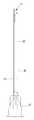
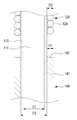
이러한 매선 요법의 시술에 사용되는 종래의 실 삽입기의 일 예가 도 1에 도시되어 있다. 예시된 종래의 실 삽입기는, 내부에서 연장하는 구멍(11)이 첨예한 선단에서 개방되고, 후단에 손잡이(12)가 구비되는 삽입바늘(10)과, 삽입바늘(10)의 구멍(11)에 길이방향으로의 일부분이 끼워지는 실(20)과, 삽입바늘(10)의 구멍(11) 외부에 나온 실(20)을 삽입바늘(10)에 대해 위치 고정시키는 고정부재(30)를 포함한다. 실 삽입기(10)에는, 시술 시 발생하는 통증이나 시술 후에 남을 수 있는 부작용을 최소화하기 위해 굵기가 가는 삽입바늘(10)이 사용되고, 삽입바늘(10)의 구멍(11)에 끼울 수 있는 굵기가 매우 가는 실(20)이 사용된다.An example of a conventional thread inserter used for the treatment of such a replenishment therapy is shown in Fig. The illustrated conventional thread inserter includes an
이러한 실 삽입기를 사용한 매선 시술 시, 삽입바늘(10)을 인체에 찔러 넣으면, 실(20)은 삽입바늘(10)에 의해 인체 내부로 이끌려 들어가게 된다. 실(20)이 인체 내부의 원하는 부위에 도달된 상태에서 삽입바늘(10)을 인체로부터 빼내면, 실(20)은 삽입바늘(10)의 구멍(11)으로부터 빠지면서 인체 내부에 남게 된다. 이와 같이 인체 내부에 삽입되는 실(20)은 인체 내부의 조직을 자극하고 당겨주어, 근육을 강화하거나 피부의 처짐이나 주름을 개선하는 효과를 준다. 이와 관련하여, 예컨대 대한민국 등록특허공보 제10-0473108호는 실 삽입기의 일 예를 제안한다.When inserting the
인체 내부에 실을 삽입하는 매선 시술을 통해 근육을 강화하거나 피부의 처짐이나 주름을 개선하는 시술 효과를 크게 얻기 위해서는, 인체 내부에 가는 실보다는 굵은 실을 삽입하는 것이 유리하다.It is advantageous to insert a thick thread rather than a thin thread inside the human body in order to strengthen the muscles through the stitching operation for inserting the thread inside the human body or to obtain a large effect of improving the sagging or wrinkling of the skin.
그런데, 종래의 실 삽입기의 경우, 매선 시술에 따른 통증과 부작용을 최소화하기 위해 가는 굵기의 삽입바늘이 사용되기 때문에 그 내부에 형성되는 구멍에 굵은 실을 끼우기 어렵다. 따라서, 종래의 실 삽입기를 사용하여 시술 효과를 크게 얻기 위해서는, 복수 회의 매선 시술을 통해 여러 가닥의 가는 실을 시술 부위에 삽입해야만 한다. 이 때문에, 시술 시간이 길어져서 시술 중 피시술자가 큰 통증을 느낄 수 있으며, 시술 후 시술 부위에 출혈이나 피멍 등과 같은 부작용이 심하게 생길 수 있는 문제점이 있다.However, in the case of the conventional thread inserter, since a thin insertion needle is used in order to minimize the pain and the side effect of the sold-out procedure, it is difficult to insert a thick thread into the hole formed therein. Therefore, in order to obtain a large effect by using the conventional thread inserter, it is necessary to insert a plurality of thin threads into the treatment site through a plurality of plating operations. Therefore, the procedure time is prolonged, so that the patient can feel a great deal of pain during the procedure, and side effects such as hemorrhage and bloating can be severely caused at the operation site after the operation.
이러한 문제점을 해결하기 위하여, 도 2에 도시한 바와 같이, 삽입바늘(10)에 나선형으로 실(40)이 감긴 실 삽입기가 제안되고 있다. 실(40)의 길이방향에 있어서의 일부(선단부)는 삽입바늘(10)의 구멍(11)에 삽입되고, 실(40)의 길이방향에 있어서의 나머지 부분은 삽입바늘(10)의 둘레에 나선형으로 감기고, 그 후단부(끝단부)는 고정부재(30)에 끼워져 고정된다. 그러나, 이러한 실 삽입기의 경우, 삽입바늘(10)의 둘레에 피치 간격(PS)이 넓게 실(40)이 감겨지고, 실(40)의 후단부가 고정부재(30)에 단순히 끼워져 고정되므로, 인체 내부에 실(40)을 삽입시키는데 어려움이 있다. 구체적으로, 실 삽입기를 사용한 매선 시술 시, 삽입바늘(10)을 인체에 바로 찔러 넣게 되면, 실(40)이 삽입바늘(10)의 둘레에 감겨진 형상을 유지하지 못하고, 삽입바늘(10)의 후방으로 밀려나면서 풀리게 된다. 따라서, 인체 내부에 실(40)이 제 형상을 유지하지 못하고 삽입되므로, 결국 시술 부위에 전체적으로 실(40)이 충분하게 채워지지 못하게 되어 큰 시술 효과를 얻기 어렵다.In order to solve such a problem, as shown in Fig. 2, a yarn inserter in which a
한편, 인체 내부에 실(40)을 나선 형상을 유지하면서 삽입하기 위해서는, 실(40)의 삽입바늘(10)의 둘레에 감겨진 방향과 피치 간격(PS)에 맞춰 삽입바늘(10)을 회전시키면서 인체에 찔러 넣어야 한다. 따라서, 실 삽입기를 사용하여 매선 시술을 하는데 상당한 어려움이 있다. 또한, 인체 내부에 나선 형상으로 실(40)을 삽입하더라도, 실(40)의 피치 간격(PS)이 넓은 형상으로 인해, 인체 내부[예컨대, 주름이나 처진 피부가 있는 부위 아래의 피하 조직 등]에서 주름을 펴거나 처진 피부를 탄력 있게 하는 실(40)의 채움 효과와 탄성 효과를 크게 기대하기 어렵다.On the other hand, in order to insert the
본 개시는 종래기술들에 따른 문제점을 해결하기 위한 것으로, 삽입바늘의 둘레에 실이 조밀하게 감겨지는 실 삽입기를 제공한다.The present disclosure provides a thread inserter for tightly threading a thread around an insertion needle.
또한, 본 개시는 삽입바늘의 둘레에 조밀하게 감겨진 실의 후단부가 매듭지어지는 실 삽입기를 제공한다.The present disclosure also provides a thread inserter in which a rear end of a thread tightly wound around an insertion needle is knotted.
본 개시의 예시적 실시예에 따른 실 삽입기는 첨예한 선단을 가지며, 길이방향으로 연장하고 상기 선단에서 개방되는 구멍을 내부에 갖는 삽입바늘과, 상기 삽입바늘의 구멍에 삽입되는 제1 연장부와, 상기 제1 연장부로부터 연장하고 상기 삽입바늘의 구멍 외부에서 상기 삽입바늘의 길이방향으로 상기 삽입바늘의 둘레에 감기는 권선부와 상기 권선부의 풀림을 방지하도록 묶이는 매듭부를 형성하는 제2 연장부를 갖는 실을 포함하고, 상기 삽입바늘에 의해 상기 실이 인체 내부에 삽입될 때, 상기 권선부는 상기 삽입바늘의 둘레에 조밀하게 감긴 형상으로 인체 내부로 유도되고 잔류된다.A thread inserter according to an exemplary embodiment of the present disclosure includes an insertion needle having a sharp tip and having a hole extending therein in the longitudinal direction and opening at the tip and a first extension portion inserted into the hole of the insertion needle, A second extending portion extending from the first extending portion and forming a winding portion wound around the insertion needle in a longitudinal direction of the insertion needle outside the hole of the insertion needle and a knot portion tied to prevent unwinding of the winding portion And when the thread is inserted into the human body by the insertion needle, the winding portion is guided and remains in the human body in a densely wound form around the insertion needle.
일 실시예에 있어서, 상기 매듭부는 상기 삽입바늘의 둘레에서 엇갈리도록 감겨진 적어도 하나의 결속부를 갖는다.In one embodiment, the knot has at least one binding portion wound to be staggered around the insertion needle.
일 실시예에 있어서, 상기 실 삽입기는 상기 삽입바늘과 상기 제2 연장부가 관통하도록 끼워지는 고정링을 더 포함하고, 상기 고정링은 상기 삽입바늘의 길이방향으로 이동 가능하고, 상기 삽입바늘의 둘레방향으로 회전 가능하다.In one embodiment, the seal inserter further includes a retaining ring which is inserted into the insertion needle and the second extending portion so as to penetrate therethrough, the retaining ring being movable in the longitudinal direction of the insertion needle, Direction.
일 실시예에 있어서, 상기 매듭부는 상기 고정링의 둘레에서 엇갈리도록 감겨진 적어도 하나의 결속부를 갖는다.In one embodiment, the knot has at least one binding portion wound to be staggered around the fixing ring.
일 실시예에 있어서, 상기 실 삽입기는 상기 삽입바늘이 이동가능하게 관통하여 끼워지는 슬라이더를 더 포함하고, 상기 슬라이더는 인체 내부로 적어도 일부가 삽입되고, 상기 매듭부와 접촉하는 헤드부를 포함한다.In one embodiment, the thread inserting device further includes a slider to which the insertion needle movably penetrates, and the slider includes a head portion at least partially inserted into the human body and in contact with the knot.
일 실시예에 있어서, 상기 슬라이더의 상기 헤드부는 상기 삽입바늘의 길이방향에서 상기 매듭부와 맞대어지는 접촉면을 포함하고, 상기 접촉면의 적어도 일부는 상기 삽입바늘의 반경외측방향으로 갈수록 상기 삽입바늘의 후방을 향해 기울어지는 경사면으로 형성된다.In one embodiment, the head portion of the slider includes a contact surface that abuts the knot portion in the longitudinal direction of the insertion needle, and at least a part of the contact surface is located in a radially outward direction of the insertion needle, As shown in Fig.
일 실시예에 있어서, 상기 슬라이더는 상기 헤드부로부터 연장하는 파지부를 더 포함한다.In one embodiment, the slider further includes a grip portion extending from the head portion.
일 실시예에 있어서, 상기 삽입바늘의 상기 실이 조밀하게 감기는 부분 중 적어도 일부에는 상기 실의 유동방지를 위한 눌림부가 구비된다.In one embodiment, at least a portion of the insertion needle which is tightly wound with the thread is provided with a pressing portion for preventing the flow of the thread.
일 실시예에 있어서, 상기 눌림부의 단면 형상은 타원 고리 형상 또는 적어도 하나의 직선 가장자리를 갖는 고리 형상을 포함한다.In one embodiment, the cross-sectional shape of the depressions comprises an elliptical annulus or an annulus having at least one straight edge.
본 개시의 실시예에 의하면, 삽입바늘의 구멍에 길이방향으로의 일부분이 끼워진 실이 삽입바늘의 구멍 외부에서 삽입바늘의 둘레에 조밀하게 감겨지고, 그 후단부가 매듭지어진다. 따라서, 인체 내부에 실을 삽입하기 위해 삽입바늘을 인체에 찔러 넣더라도 삽입바늘의 후방으로 실이 밀려나거나, 실이 임의로 풀어지는 것을 방지할 수 있다. 따라서, 종래와 비교하여 삽입바늘을 회전시키면서 인체에 찔러 넣지 않아도 되므로, 실 삽입기의 사용이 편리하다.According to the embodiment of the present disclosure, a thread in which a portion in the longitudinal direction is fitted in the hole of the insertion needle is tightly wound around the insertion needle outside the hole of the insertion needle, and the rear end thereof is knotted. Therefore, even if the insertion needle is inserted into the human body in order to insert the thread into the human body, the thread can be prevented from being pushed rearward of the insertion needle or the thread can be prevented from being arbitrarily released. Therefore, compared to the conventional art, it is not necessary to insert the insertion needle into the human body while rotating the insertion needle, so that the use of the thread inserter is convenient.
또한, 삽입바늘을 인체에 찔러 넣는 것만으로도 삽입바늘의 둘레에 조밀하게 감겨진 형상으로 실을 인체 내부에 삽입시킬 수 있다. 따라서, 종래의 여러 번의 시술을 통해 여러 가닥의 실을 인체 내부에 삽입하거나 또는 피치 간격이 넓은 나선형의 실을 인체 내부에 삽입하는 것과 비교하여, 한 번의 시술로도 채움 효과와 탄성 효과가 큰 시술 효과를 기대할 수 있다. 또한, 원하는 시술 효과를 얻는데 있어서 시술 횟수와 시술 시간을 현저하게 줄일 수 있다.In addition, by inserting the insertion needle into the human body, the thread can be inserted into the human body in a densely wound form around the insertion needle. Therefore, compared with a case in which a plurality of strands are inserted into the human body through a plurality of conventional procedures, or a spiral thread having a wide pitch interval is inserted into the human body, a filling operation and a large elastic effect Effect can be expected. In addition, the number of procedures and the procedure time can be remarkably reduced in obtaining a desired treatment effect.
또한, 실 삽입기에 적어도 일부분이 삽입바늘과 함께 인체 내부에 삽입되는 슬라이더를 구비함으로써, 실의 매듭지어진 부분까지 인체 내부에 용이하게 삽입시킬 수 있다. 따라서, 매선 시술 시 인체 외부로 나오는 실의 후단부를 커팅을 통해 제거해야 하는 번거로움을 줄일 수 있다.Further, since the thread inserter includes the slider at least a part of which is inserted into the human body together with the insertion needle, the knotted portion of the thread can be easily inserted into the human body. Accordingly, it is possible to reduce the inconvenience of removing the rear end of the thread coming out of the human body through the cutting process.
또한, 삽입바늘의 실이 조밀하게 감겨지는 부분에 실의 유동방지를 위한 눌림부를 형성하고, 눌림부에 실이 조밀하게 감겨지도록 함으로써, 인체 내부에 삽입된 실이 피부 조직에 의해 눌리거나 또는 인체 외부에서 가해지는 힘에 의해 눌리더라도, 시술 부위에서 임의로 위치 이동하는 것을 방지할 수 있다. 따라서, 피부의 처짐이나 주름을 개선하고자 하는 시술 효과를 원하는 시술 부위에 효과적으로 발생시킬 수 있다.In addition, a pressing portion for preventing the flow of the thread is formed in a portion where the thread of the insertion needle is densely wound, and the thread is tightly wound around the pressing portion, so that the thread inserted into the inside of the human body is pressed by the skin tissue, Even if the force is exerted by an externally applied force, it is possible to prevent the positional movement arbitrarily from the treatment site. Therefore, it is possible to effectively generate a treatment effect for improving the sagging or wrinkling of the skin on the desired treatment site.
도 1은 종래의 실 삽입기의 일 예를 도시한 도면이다.
도 2는 종래의 실 삽입기의 다른 예를 도시한 도면이다.
도 3은 본 개시의 제1 실시예에 따른 실 삽입기를 도시한 도면이다.
도 4는 도 3에 도시한 실 삽입기의 일 부분에 대한 단면도이다.
도 5는 도 3에 도시한 A부분의 확대도이다.
도 6은 도 3에 도시한 실 삽입기를 사용한 매선 시술의 예를 도시한 도면이다.
도 7은 도 6에 도시한 매선 시술의 예에 따라 인체 내부에 삽입되는 실을 도시한 도면이다.
도 8은 본 개시의 제2 실시예에 따른 실 삽입기를 도시한 도면이다.
도 9는 도 8에 도시한 B부분의 확대도이다.
도 10은 본 개시의 제3 실시예에 따른 실 삽입기를 도시한 도면이다.
도 11은 도 10에 도시한 슬라이더의 일부를 도시한 단면도이다.
도 12는 도 10에 도시한 슬라이더의 다른 예를 도시한 단면도이다.
도 13은 도 10에 도시한 실 삽입기를 사용한 매선 시술의 예를 도시한 도면이다.
도 14는 일 실시예에 따른 실 삽입기에 있어서의 눌림부가 형성된 삽입바늘의 일부분을 도시한 도면이다.
도 15는 도 14에 도시한 눌림부에 감겨 형성된 실의 인체 내부에 삽입된 예를 도시한 도면이다.
도 16은 도 14에 도시한 눌림부의 다른 예에 따른 단면 형상을 도시한 도면이다.1 is a view showing an example of a conventional thread inserter.
2 is a view showing another example of a conventional thread inserter.
3 is a view showing a seal inserting device according to the first embodiment of the present disclosure.
4 is a cross-sectional view of a portion of the seal inserting apparatus shown in Fig.
5 is an enlarged view of the portion A shown in Fig.
Fig. 6 is a view showing an example of a book marking operation using the seal inserting machine shown in Fig. 3;
7 is a view showing a thread inserted into the human body according to the example of the book marking procedure shown in Fig.
8 is a view showing a seal inserter according to a second embodiment of the present disclosure.
9 is an enlarged view of a portion B shown in Fig.
10 is a view showing a seal inserter according to a third embodiment of the present disclosure.
11 is a sectional view showing a part of the slider shown in Fig.
12 is a cross-sectional view showing another example of the slider shown in Fig.
Fig. 13 is a view showing an example of a book marking operation using the seal inserting machine shown in Fig. 10;
14 is a view showing a portion of an insertion needle having a pressing portion in a thread inserter according to an embodiment.
Fig. 15 is a view showing an example in which the thread wound on the pressing portion shown in Fig. 14 is inserted into the human body.
Fig. 16 is a view showing a sectional shape according to another example of the pressing portion shown in Fig. 14;
본 개시의 실시예들은 본 개시의 기술적 사상을 설명하기 위한 목적으로 예시된 것이다. 본 개시에 따른 권리범위가 이하에 제시되는 실시예들이나 이들 실시예들에 대한 구체적 설명으로 한정되는 것은 아니다.The embodiments of the present disclosure are illustrated for the purpose of describing the technical idea of the present disclosure. The scope of the claims according to the present disclosure is not limited to the embodiments described below or to the detailed description of these embodiments.
본 개시에 사용되는 모든 기술적 용어들 및 과학적 용어들은, 달리 정의되지 않는 한, 본 개시가 속하는 기술 분야에서 통상의 지식을 가진 자에게 일반적으로 이해되는 의미를 갖는다. 본 개시에 사용되는 모든 용어들은 본 개시를 더욱 명확히 설명하기 위한 목적으로 선택된 것이며 본 개시에 따른 권리범위를 제한하기 위해 선택된 것이 아니다.All technical and scientific terms used in the present disclosure have the meaning commonly understood by one of ordinary skill in the art to which this disclosure belongs unless otherwise defined. All terms used in the disclosure are selected for the purpose of more clearly illustrating the disclosure and are not chosen to limit the scope of the rights under the present disclosure.
본 개시에서 사용되는 "포함하는", "구비하는", "갖는" 등과 같은 표현은, 해당 표현이 포함되는 어구 또는 문장에서 달리 언급되지 않는 한, 다른 실시예를 포함할 가능성을 내포하는 개방형 용어(open-ended terms)로 이해되어야 한다.As used in this disclosure, expressions such as " comprising, "" having," "having, " and the like, unless the context requires otherwise, (open-ended terms).
본 개시에서 사용되는 "제1", "제2" 등의 표현들은 복수의 구성요소들을 상호 구분하기 위해 사용되며, 해당 구성요소들의 순서 또는 중요도를 한정하는 것은 아니다.As used in this disclosure, expressions such as " first ", "second ", and the like are used to distinguish a plurality of components from each other and do not limit the order or importance of the components.
이하, 첨부한 도면들을 참조하여, 본 개시의 실시예들을 설명한다. 첨부된 도면에서, 동일하거나 대응하는 구성요소에는 동일한 참조번호가 부여되어 있다. 또한, 이하의 실시예들의 설명에 있어서, 동일하거나 대응하는 구성요소를 중복하여 기술하는 것이 생략될 수 있다. 그러나, 구성요소에 관한 기술이 생략되어도, 그러한 구성요소가 어떤 실시예에 포함되지 않는 것으로 의도되지는 않는다.Hereinafter, embodiments of the present disclosure will be described with reference to the accompanying drawings. In the accompanying drawings, the same or corresponding components are denoted by the same reference numerals. In the following description of the embodiments, description of the same or corresponding components may be omitted. However, even if a description of components is omitted, such components are not intended to be included in any embodiment.
도 3은 본 개시의 제1 실시예에 따른 실 삽입기를 도시한 도면이다. 또한, 도 4는 도 3에 도시한 실 삽입기의 일 부분에 대한 단면도이고, 도 5는 도 3에 도시한 A부분의 확대도이다.3 is a view showing a seal inserting device according to the first embodiment of the present disclosure. 4 is a cross-sectional view of one portion of the seal inserting apparatus shown in Fig. 3, and Fig. 5 is an enlarged view of a portion A shown in Fig.
도 3 내지 도 5를 참조하여 제1 실시예에 따른 실 삽입기(100)를 설명한다. 도 3에서, 화살표(FD)는 삽입바늘(110)의 선단 측을 향하는 방향을 가리키고, 화살표(RD)는 삽입바늘(110)의 후단 측을 향하는 방향을 가리킨다. 실시예에 따른 삽입바늘(110)은 당해 분야에 있어서, '주사바늘' 등으로 참조될 수 있다.The
도 2에 도시한 바와 같이, 실 삽입기(100)는 삽입바늘(110)과 실(120)을 포함한다. 이러한 실 삽입기(100)는 고정링(130)을 더 포함할 수 있다.As shown in FIG. 2, the
삽입바늘(110)은 가늘고 긴 관 형상을 가지며, 인체에 찔러 넣을 수 있도록 첨예한 선단을 가진다. 삽입바늘(110)은 그 내부에서 길이방향으로 연장하고 선단에서 개방되는 구멍(111)을 가지며, 후단에는 시술자가 손가락 등으로 잡을 수 있는 손잡이(112)가 구비된다. 손잡이(112)에는 그 후방(RD)으로, 시술자가 손가락이나 손바닥에 돌기물을 잡는 것 같은 이물감 및 위화감을 느끼지 않고, 안정된 그립감으로 실 삽입기(100)를 잡을 수 있도록 보조 손잡이(113)가 분리가능하게 결합될 수 있다. 보조 손잡이(113)는 손잡이(112)와 끼움 방식으로 결합될 수 있으며, 주사기 등의 형상을 가질 수 있다.The
삽입바늘(110)은 금속 재료로 형성되고, 손잡이(112) 및 보조 손잡이(113)는 플라스틱 재료로 형성되지만, 이에 한정되는 것은 아니다. 예컨대, 삽입바늘(110)은 플라스틱 재료, 특히 그 내부의 구멍(111)에 삽입되는 실(120)을 육안으로 확인할 수 있도록 투명한 플라스틱 재료로 형성될 수 있다. 또한, 손잡이(112)와 보조 손잡이(113)는 금속 재료로 형성되거나, 금속 재료와 플라스틱 재료가 복합되어 형성될 수도 있다. 또한, 삽입바늘(110)의 내부에 형성되는 구멍(111)은 삽입바늘(110)의 전체 길이에 걸쳐서 형성될 수 있으며, 또는 이와 달리 삽입바늘(110)의 선단으로부터 소정 길이만큼만 그 내부에서 연장하도록 형성될 수도 있다.The
실(120)은 인체에 삽입되어 근육을 강화하거나, 노화된 피부를 재생하고 피부 탄력을 향상시켜 피부의 처짐이나 주름을 개선하기 위한 것으로, 수술용 봉합사를 포함한다. 특히, 실(120)은 인체 내부에서 분해되어 없어지는 생분해성 봉합사(biodegradable suture thread)를 포함한다.The
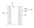
실(120)은 그 길이방향으로 삽입바늘(110)의 구멍(111)에 끼워지는 제1 연장부(121)와, 제1 연장부(121)로부터 연장하여 삽입바늘(110)의 구멍(111) 외부로 나오는 제2 연장부(122)를 포함한다. 실(120)의 제1 연장부(121)는, 인체 내부에 실(120)을 삽입할 때 삽입바늘(110)의 구멍(111)으로부터 임의로 빠지지 않도록 삽입바늘(110)의 구멍(111)에 충분한 길이로 삽입된다. 실(120)의 제2 연장부(122)는, 삽입바늘(110)의 구멍(111)에 인접한 부분(예컨대, 삽입바늘(110)의 첨예한 선단에서의 후방 부분)으로부터 삽입바늘(110)의 후방(RD)으로 삽입바늘(110)의 둘레에 조밀하게 감기는 권선부(123)와, 권선부(123)로부터 연장되는 실(120)의 후단부(끝단부)를 매듭지어 형성한 매듭부(124)를 포함한다.The
도 4에 도시한 바와 같이, 권선부(123)는 실(120)의 권선(예컨대, 삽입바늘의 둘레에 한번 감겨진 부분)(123A)과 이와 인접한 다른 권선(123B)이 서로 밀착되게 감겨진 부분으로서, 권선들(123A, 123B) 사이에 틈새가 없어 권선부(123)가 형성된 부분의 삽입바늘(110)은 외부에 노출되지 않는다. 실 삽입기(100)에 있어서의 권선부(123)의 길이(L1)(도 3 참조)는, 시술 부위에 따라 달라질 수 있으며, 시술 부위에서의 피부의 처짐 정도, 주름의 깊이나 크기 등에 따라서도 달라질 수 있다.As shown in Fig. 4, the winding
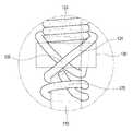
매듭부(124)는, 도 5에 도시한 바와 같이, 삽입바늘(110)의 둘레에서 엇갈리도록 감기는 적어도 하나의 결속부(125)를 포함한다. 실시예에서는, 실(120)의 후단부(삽입바늘의 구멍에 삽입되는 단부와 반대되는 단부) 자체가 적어도 하나의 결속부(125)를 갖도록 묶여 매듭부(124)를 형성하지만, 이에 한정되는 것은 아니다. 예컨대, 다른 실시예에서는, 별도의 실을 사용하여 실(120)의 후단부를 삽입바늘(110)의 둘레에 고정되도록 감고 묶어서 매듭부를 형성할 수도 있다. 실시예에서는, 권선부(123)의 후방(RD)에 삽입바늘(110)의 둘레에 묶이는 매듭부(124)를 형성함으로써, 실 삽입기(100)의 보관, 운반, 사용 등에 따른 취급 시 권선부(123)가 예기치 않게 풀리는 것을 방지할 수 있다. 또한, 매듭부(124)는 실 삽입기(100)를 사용한 매선 시술 시, 권선부(123)가 삽입바늘(110)의 후방(RD)으로 밀리는 것을 방지하여, 권선부(123)를 인체 내부에 용이하게 삽입할 수 있도록 한다.The
고정링(130)은 실(120)의 제2 연장부(122)를 삽입바늘(110)에 대해 위치 고정시키기 위한 것으로, 탄성 재료로 형성된다. 예컨대, 고정링(130)은 스폰지나 고무 등의 재료로 형성될 수 있다. 고정링(130)의 내측으로 삽입바늘(110)과 실(120)이 끼워진다. 고정링(130)의 내측에 끼워지는 실(120)은 권선부(123)와 매듭부(124)를 형성하기 전의 제2 연장부(122)일 수 있다. 고정링(130)에는 삽입바늘(110)이 밀착된 상태로 끼워지며, 이러한 고정링(130)은 삽입바늘(110)의 길이방향으로 이동이 가능하고, 삽입바늘(110)의 둘레방향으로 회전이 가능하다.The fixing
고정링(130)은 권선부(123)를 형성하는데 사용될 수 있다. 예컨대, 고정링(130)의 내측으로 삽입바늘(110)과 제2 연장부(122)가 관통하도록 끼워진 후, 고정링(130)을 삽입바늘(110)의 둘레방향으로 회전시킴과 동시에 삽입바늘(110)의 후방(RD)으로 이동시켜 고정링(130)의 내측에 끼워진 실(120)[제2 연장부(122)]이 삽입바늘(110)의 둘레에 조밀하게 감기도록 하여 권선부(123)를 형성할 수 있다. 실시예에서는, 고정링(130)에 의해 권선부(123)를 형성하는 것을 예로 들어 설명하였지만, 이에 한정되는 것은 아니다. 예컨대, 권선 장치를 사용하여 권선부(123)를 형성할 수도 있다.The
도 6은 도 3에 도시한 실 삽입기를 사용한 매선 시술의 예를 도시한 도면이고, 도 7은 도 6에 도시한 매선 시술의 예에 따라 인체 내부에 삽입되는 실을 도시한 도면이다.FIG. 6 is a view showing an example of a bookbinding operation using the seal inserting apparatus shown in FIG. 3, and FIG. 7 is a view showing a yarn inserted into the human body according to the example of the bookbinding operation shown in FIG.
도 6 및 도 7을 참조하여 실 삽입기(100)를 사용한 매선 시술의 예, 즉 실 삽입기(100)를 사용한 실 삽입방법에 대해 설명한다. 피부(S)의 처짐이나 주름(L)을 개선하고자 하는 시술 부위[예를 들어, 도 6에서, 주름(L) 아래의 피하 조직(K)]에 실 삽입기(100)의 선단을 대고 찔러 넣는다. 이때, 시술자는 실 삽입기(100)를 회전시키지 않고, 권선부(123) 후방(RD)에 형성한 매듭부(124)를 잡은 상태에서 삽입바늘(110)을 인체 내부로 찔러 넣을 수 있다. 실시예의 실 삽입기(100)에서는, 삽입바늘(110)의 둘레에 틈새없이 조밀하게 감겨지도록 권선부(123)가 형성되므로, 삽입바늘(110)을 회전시키지 않고 인체에 바로 찔러 넣더라도, 권선부(123)가 삽입바늘(110)의 길이방향으로 밀리지 않는다. 또한, 실시예의 실 삽입기(100)에서는, 권선부(123)의 바로 뒤쪽으로 매듭부(124)를 형성하고, 이러한 매듭부(124)를 삽입바늘(110)을 인체에 찔러 넣을 때 잡고 지탱할 수 있도록 함으로써, 권선부(123)가 삽입바늘(110)의 후방(RD)으로 밀려 인체 내부에 삽입되지 못하거나, 권선부(123)가 풀리는 것을 방지할 수 있다. 따라서, 권선부(123)를 포함하는 실(120)을, 삽입바늘(110)의 둘레에 조밀하게 감겨진 권선부(123)의 형상(예컨대 인장 스프링이나 코일 형상)을 유지한 상태로 인체 내부에 삽입할 수 있다.With reference to Figs. 6 and 7, an example of a bookbinding operation using the
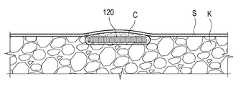
실(120)의 권선부(123)가 완전히 인체 내부에 삽입되면, 실 삽입기(100)를 삽입바늘(110)의 둘레방향으로 회전시키면서 인체 내부로 더 찔러 넣어 매듭부(124)도 인체 내부에 삽입시킬 수 있다. 이와 같이 실(120) 전체가 인체 내부에 삽입되면, 인체 외부에서 피하 조직(K)에 위치된 매듭부(124)을 손으로 누른 상태에서 삽입바늘(110)을 인체로부터 빼내면, 삽입바늘(110)의 구멍(111)으로부터 실(120)의 제1 연장부(121)가 빠지면서, 실(120)만 피하 조직(K) 내에 남게 된다(도 7 참조). 이러한 실(120)은, 종래의 한 가닥 또는 몇 가닥으로 인체 내부에 삽입되는 실에 비해, 피하 조직(K) 내에 큰 볼륨을 갖도록 채워지게 되므로, 근육을 강화하거나 피부의 처짐이나 주름을 개선하는 시술 효과를 크게 발생시킨다. 즉, 종래의 한 가닥 또는 몇 가닥으로 인체 내부에 삽입되는 실에 비해, 실(120)의 주위에 많은 양의 콜라겐(C)이 모이도록 피하 조직(K)을 자극할 수 있어서, 실(120)의 주위가 상대적으로 크게 볼록해지며, 이러한 실(120)은 처진 피부(S)를 탄력 있게 하거나, 주름(L)을 펴지도록 한다.When the winding
도 8은 본 개시의 제2 실시예에 따른 실 삽입기를 도시한 도면이고, 도 9는 도 8에 도시한 B부분의 확대도이다.FIG. 8 is a view showing a seal inserting machine according to a second embodiment of the present disclosure, and FIG. 9 is an enlarged view of a portion B shown in FIG.
도 8 및 도 9를 참조하면, 제2 실시예에 따른 실 삽입기(200)는 제1 실시예의 실 삽입기(100)와 동일한 구성을 가지면서, 매듭부(124)가 고정링(130)의 둘레에 엇갈리도록 감겨 형성된다. 매듭부(124)는 삽입바늘(110)의 둘레에 엇갈리도록 감기는 적어도 하나의 결속부(125)를 포함한다. 또한, 매듭부(124)는 고정링(130)의 둘레에 엇갈리도록 감기는 결속부(126)를 더 포함할 수 있다. 이러한 실 삽입기(200)에서와 같이, 매듭부(124)의 적어도 일부가 고정링(130)의 둘레에 감기도록 형성함으로써, 매듭부(124)를 보다 용이하게 형성할 수 있으며, 권선부(123)의 밀림이나 풀림을 보다 효과적으로 방지할 수 있다. 또한, 시술자는, 매선 시술 시에 탄성 재료로 형성되는 고정링(130)을 잡고 권선부(123)가 삽입바늘(110)의 후방(RD)으로 밀리지 않도록 지탱할 수 있으므로, 실(120)을 인체 내부에 삽입시키는데 있어서 실 삽입기(200)의 사용이 간편해진다.8 and 9, the
실 삽입기(200)를 사용한 매선 시술 시, 삽입바늘(100)을 인체에 찔러 넣어 실(120)의 권선부(123)가 인체 내부에 완전히 삽입되면, 고정링(130)에 감겨진 매듭부(124)의 일부를 커팅한 후, 실 삽입기(200)를 삽입바늘(110)의 둘레방향으로 회전시키면서 인체 내부로 더 찔러 넣어 권선부(123)에 연결된 매듭부(124)도 인체 내부로 삽입할 수 있다.When the
도 10은 본 개시의 제3 실시예에 따른 실 삽입기를 도시한 도면이다. 도 11은 도 10에 도시한 슬라이더의 일부를 도시한 단면도이고, 도 12는 도 10에 도시한 슬라이더의 다른 예를 도시한 단면도이다. 또한, 도 13은 도 10에 도시한 실 삽입기를 사용한 매선 시술의 예를 도시한 도면이다.10 is a view showing a seal inserter according to a third embodiment of the present disclosure. Fig. 11 is a cross-sectional view showing a part of the slider shown in Fig. 10, and Fig. 12 is a cross-sectional view showing another example of the slider shown in Fig. 13 is a diagram showing an example of a book marking operation using the seal inserter shown in Fig.
도 10 내지 도 13을 참조하면, 제3 실시예에 따른 실 삽입기(300)는 전술한 제1 실시예의 실 삽입기(100)와 같이 삽입바늘(110), 실(120)을 포함하며, 삽입바늘(110)이 이동가능하게 관통하여 끼워지는 슬라이더(140)를 더 포함한다. 실 삽입기(300)는, 제1 실시예의 실 삽입기(100)에서와 같이, 권선부(123)를 형성할 수 있는 고정링(130)을 더 포함할 수 있다. 이 경우, 고정링(130)은 실 삽입기(300)를 매선 시술에 사용할 때 삽입바늘(110)로부터 분리될 수 있다.10 to 13, the
슬라이더(140)는, 삽입바늘(110)이 내측에 끼워지는 관 형상을 가진다. 슬라이더(140)는 삽입바늘(110)의 외경(D1)과 동일한 크기의 내경(D3)을 가질 수 있다.The
슬라이더(140)는 매듭부(124)의 후방(RD)에 위치되어 삽입바늘(110)에 대해 전방(FD) 또는 후방(RD)으로 슬라이딩 직선 이동하도록 결합된다. 이러한 슬라이더(140)는 매선 시술 시 적어도 일부가 인체 내부에 삽입될 수 있는 헤드부(141)를 포함한다(도 13 참조). 슬라이더(140)의 헤드부(141)에 의해 실(120)의 후단부, 즉 매듭부(124)가 피부(S) 외부로 노출되지 않도록 실(120)을 인체 내부에 삽입시킬 수 있다.The
삽입바늘(110)을 인체 내부에 찔러 넣을 때, 슬라이더(140)는 헤드부(141)에 접촉되는 매듭부(124)를 지탱하여, 실(120)이 삽입바늘(110)의 후방(RD)으로 밀려나는 것을 방지한다. 슬라이더(140)의 헤드부(141)는 매듭부(124)와 접촉할 수 있도록 삽입바늘(110)의 선단을 향하는 부분에 접촉면(142)을 포함한다. 접촉면(142)은, 도 11에 도시한 바와 같이 평면으로 형성될 수 있다. 삽입바늘(110)의 둘레면에서 돌출하는 접촉면(142)의 높이(H1)는, 실(120)의 후단부를 용이하게 지탱할 수 있도록, 삽입바늘(110)의 둘레면에 감긴 실(120)의 직경(D2)과 대략 동일한 크기로 형성될 수 있다. 또한, 접촉면(142)은, 도 12에 도시한 바와 같이, 일부는 평면(143)으로 형성되고, 나머지 일부는 삽입바늘(110)의 반경외측방향(ROD)으로 갈수록 삽입바늘(110)의 후방(RD)을 향해 기울어지는 경사면(144)으로 형성될 수 있다. 또한, 접촉면(142)은 그 전체가 경사면(144)으로 형성될 수 있다. 이러한 슬라이더(140)는 첨예한 형상의 헤드부(141)를 구비함으로써 그 일부분(접촉면을 포함하는 선단 부분)이 인체 내부에 용이하게 삽입될 수 있다. 구체적으로, 도 13에 도시한 바와 같이, 실 삽입기(300)를 사용한 매선 시술 시, 삽입바늘(110)을 인체에 찔러 넣어 권선부(123)가 인체 내부에 삽입되도록 한다. 이때, 슬라이더(140)를 삽입바늘(110)의 전방(FD)으로 이동시켜 헤드부(141)의 선단부에 매듭부(124)가 접촉되도록 하여 실(120)이 슬라이더(140)의 후방(RD)으로 밀리는 것을 방지할 수 있다. 또한, 삽입바늘(110)과 함께 슬라이더(140)를 인체 내부에 찔러 넣어 헤드부(141)의 일부분이 인체 내부에 찔러 넣어지도록 함으로써, 헤드부(141)에 의해 지탱되는 매듭부(124)도 인체 내부로 밀어 삽입시킬 수 있다. 슬라이더(140)의 헤드부(141) 일부분이 인체 내부에 삽입된 상태, 즉 헤드부(141)에 의해 실(120)의 후단부가 인체 내부에서 인체 외부로 빠지지 않도록 지탱되는 상태에서, 삽입바늘(110)을 인체로부터 빼내어 삽입바늘(110)로부터 실(120)을 분리시킬 수 있으며, 이후 헤드부(141)를 인체로부터 빼냄으로써 인체 내부로 실(120)을 유도하여 인체 내부에 실(120)을 잔류시킬 수 있다.When the
슬라이더(140)가 채용된 실 삽입기(300)에서는, 매선 시술 시 헤드부(141)의 일부분이 인체 내부에 찔러 넣어질 수 있어서, 권선부(123)와 함께 매듭부(124)도 인체 내부에 용이하게 삽입할 수 있다. 또한, 실 삽입기(300)는, 매선 시술 시 삽입바늘(110)을 회전시키지 않으면서도 인체 내부에 권선부(123)의 형상을 그대로 유지하면서 실(120)을 삽입할 수 있어서, 그 사용이 간편하다.A part of the
슬라이더(140)는, 삽입바늘(110)을 인체에 찔러 넣을 때 매듭부(124)를 인체 내부로 용이하게 밀어 넣기 위해서, 또한 헤드부(141)를 용이하게 잡고 실(120)의 밀림을 방지할 수 있도록, 헤드부(141)로부터 삽입바늘(110)의 후방(RD)으로 연장하는 파지부(145)를 더 포함할 수 있다.The
도 14는 일 실시예에 따른 실 삽입기에 있어서의 눌림부가 형성된 삽입바늘의 일부분을 도시한 도면이다. 또한, 도 15는 도 14에 도시한 눌림부에 감겨 형성된 실의 인체 내부에 삽입된 예를 도시한 도면이다. 또한, 도 16은 도 14에 도시한 눌림부의 다른 예에 따른 단면 형상을 도시한 도면이다.14 is a view showing a portion of an insertion needle having a pressing portion in a thread inserter according to an embodiment. Fig. 15 is a diagram showing an example in which a thread formed by winding around the pressing portion shown in Fig. 14 is inserted into the human body. Fig. 16 is a view showing a cross-sectional shape according to another example of the pressing portion shown in Fig.
전술한 실시예들에 따른 실 삽입기(100, 200, 300)에는 원형 고리 형상의 단면 형상을 갖는 삽입바늘(110)이 채용되었지만, 삽입바늘(110)은 이에 한정되는 것은 아니다. 도 14에 도시한 바와 같이, 실 삽입기(100, 200, 300)에는 길이방향으로의 일부분에 눌림부(115)가 형성되는 삽입바늘(110A)이 채용될 수도 있다. 눌림부(115)는, 삽입바늘(110A)에 있어서의 실(120)이 조밀하게 감기는 부분 중 적어도 일부에 형성될 수 있다. 이러한 눌림부(115)는 인체 내부에 삽입되는 실(120)의 유동방지를 위해 형성된 것으로, 도 15에 도시한 바와 같이, 인체 내부에 삽입된 실(120)이 피부(S), 피하 조직(K) 등에 의해 눌리는 힘(F1)을 받거나 또는 인체 외부에서 눌리는 힘(F2)을 받더라도, 인체 내부에 삽입된 실(120)의 길이방향에 있어서의 일부분이 힘(F1, F2)이 가해지는 방향으로 탄성 변형이 용이한 코일 형상으로 되어 있어서, 상기 힘(F1, F2)에 의해 실(120)이 시술 부위에서 임의로 위치 이동(예컨대, 도 15에서, 좌측방(LSD) 또는 우측방(RSD)으로의 이동)하는 것을 방지할 수 있다. 따라서, 피부(S)의 처짐이나 주름(L)을 개선하고자 하는 시술 부위에 실(120)이 안정적으로 채워지도록 함으로써 시술 부위에 효과적으로 시술 효과를 발생시킬 수 있다.Although the insertion needles 110 having a circular ring-shaped sectional shape are employed in the
눌림부(115)는, 삽입바늘(110)의 일부분을 가압하여 형성할 수 있다. 실시예에서는, 삽입바늘(110A)에 하나의 눌림부(115)가 형성되는 것을 예로 들어 설명하였지만, 이에 한정되는 것은 아니다. 예컨대, 삽입바늘(110A)에는 복수의 눌림부(115)가 일정한 간격을 두고 형성될 수도 있다. 또한, 실시예에서는, 눌림부(115)가 상기 힘(F1, F2)에 의해 측방으로 밀려나지 않도록 원형 고리 형상이 아닌 타원 고리 형상의 단면 형상을 갖도록 형성되었지만, 이에 한정되는 것은 아니다. 예를 들어, 도 16에 도시한 바와 같이, 눌림부(115)는 힘(F1, F2)을 받는 부분으로서, 적어도 하나의 직선 가장자리(116)를 갖는 고리 형상의 단면 형상을 가질 수 있다. 또한, 눌림부(115)는 삼각 고리 형상, 사각 고리 형상 등과 같은 다각형의 고리 형상의 단면 형상을 가질 수도 있다. 눌림부(115)의 내측에 형성되는 변형된 구멍(111)에는, 실(120)의 제1 연장부(121)가 끼워질 수 있도록, 변형된 구멍(111)에서의 최소의 내경(d)은 실(120)[제1 연장부(121)]의 직경(D2)보다 크게 형성된다. 슬라이더(140)가 결합된 실 삽입기(300)에 눌림부(115)가 형성되는 삽입바늘(110A)이 채용되는 경우, 슬라이더(140)는 삽입바늘(110A)이 내측에 이동가능하게 끼워질 수 있도록 삽입바늘(110A)과 상보적인 형상으로 이루어질 수 있다.The
전술한 실시예들에 따른 실 삽입기(100, 200, 300)는 얼굴 등의 피하 조직에 실(120)을 삽입하여 피부 또는 근육을 팽팽하게 당겨서 주름을 개선하거나 피부 조직을 탄력 있게 한다. 이러한 실 삽입기(100, 200, 300)에 있어서, 삽입바늘(110, 110A)의 둘레에 실(120)이 틈새가 없이 조밀하게 감겨지므로 삽입바늘(110, 110A)을 회전시키지 않으면서 인체에 찔러 넣을 수 있다. 따라서, 실 삽입기(100, 200, 300)의 사용이 편리하다. 또한, 시술 부위에 실(120)을 삽입바늘(110, 110A)의 둘레에 감겨진 형상 그대로 삽입할 수 있어서, 시술 부위의 채움 효과를 증대시킬 수 있다. 즉, 인체 내부에 실(120)을 삽입하여 근육을 강화하거나 피부의 처짐이나 주름을 개선하는 시술 효과를 향상시킬 수 있다. 또한, 매선 시술에 소요되는 시간과 원하는 시술 효과를 얻기 위해 시술하는 횟수를 현저하게 줄일 수 있으며, 피시술자가 느끼는 고통을 줄이고 시술 후의 부작용의 발생도 최소화할 수 있다.The
이상에서 설명한 본 개시는 전술한 실시예 및 첨부된 도면에 의해 한정되는 것은 아니다. 본 개시의 기술적 사상을 벗어나지 않는 범위 내에서 여러 가지 치환, 변형 및 변경이 가능하다는 것이 본 개시가 속하는 기술 분야에서 통상의 지식을 가진 자에게 있어서 명백할 것이다.The present disclosure described above is not limited to the above-described embodiments and the accompanying drawings. It will be apparent to those skilled in the art that various substitutions, alterations, and changes can be made without departing from the spirit of the present disclosure.
110, 110A: 삽입바늘 111: 구멍
112: 손잡이 113: 보조 손잡이
115: 눌림부 120: 실
121: 제1 연장부 122: 제2 연장부
123: 권선부 124: 매듭부
125, 126: 결속부 130: 고정링
140: 슬라이더 141: 헤드부
145: 파지부 100, 200, 300: 실 삽입기110, 110A: insertion needle 111: hole
112: handle 113: auxiliary handle
115: pressing part 120: thread
121: first extension part 122: second extension part
123: winding part 124: knot part
125, 126: Coupling unit 130: Fixing ring
140: Slider 141: Head part
145:
Claims (9)
Translated fromKorean상기 삽입바늘의 구멍에 삽입되는 제1 연장부와, 상기 제1 연장부로부터 연장하고 상기 삽입바늘의 구멍 외부에서 상기 삽입바늘의 길이방향으로 상기 삽입바늘의 둘레에 감기는 권선부와 상기 권선부의 풀림을 방지하도록 묶이는 매듭부를 형성하는 제2 연장부를 갖는 실을 포함하고,
상기 삽입바늘에 의해 상기 실이 인체 내부에 삽입될 때, 상기 권선부는 상기 삽입바늘의 둘레에 조밀하게 감긴 형상으로 인체 내부로 유도되고 잔류되고,
상기 매듭부는 상기 삽입바늘의 둘레에서 엇갈리도록 감겨진 적어도 하나의 결속부를 갖는, 실 삽입기.An insertion needle having a sharp tip and extending in the longitudinal direction and having a hole therein opened at the tip,
A winding portion extending from the first extending portion and wound around the insertion needle in the longitudinal direction of the insertion needle outside the hole of the insertion needle; And a thread having a second extension forming a knot tied to prevent loosening,
When the yarn is inserted into the human body by the insertion needle, the winding portion is guided and remains in the human body in a densely wound form around the insertion needle,
Wherein the knot has at least one binding portion wound to be staggered around the insertion needle.
상기 삽입바늘의 구멍에 삽입되는 제1 연장부와, 상기 제1 연장부로부터 연장하고 상기 삽입바늘의 구멍 외부에서 상기 삽입바늘의 길이방향으로 상기 삽입바늘의 둘레에 감기는 권선부와 상기 권선부의 풀림을 방지하도록 묶이는 매듭부를 형성하는 제2 연장부를 갖는 실을 포함하고,
상기 삽입바늘에 의해 상기 실이 인체 내부에 삽입될 때, 상기 권선부는 상기 삽입바늘의 둘레에 조밀하게 감긴 형상으로 인체 내부로 유도되고 잔류되고,
상기 삽입바늘과 상기 제2 연장부가 관통하도록 끼워지는 고정링을 더 포함하고,
상기 고정링은 상기 삽입바늘의 길이방향으로 이동 가능하고, 상기 삽입바늘의 둘레방향으로 회전 가능하며,
상기 매듭부는 상기 고정링의 둘레에서 엇갈리도록 감겨진 적어도 하나의 결속부를 갖는, 실 삽입기.An insertion needle having a sharp tip and extending in the longitudinal direction and having a hole therein opened at the tip,
A winding portion extending from the first extending portion and wound around the insertion needle in the longitudinal direction of the insertion needle outside the hole of the insertion needle; And a thread having a second extension forming a knot tied to prevent loosening,
When the yarn is inserted into the human body by the insertion needle, the winding portion is guided and remains in the human body in a densely wound form around the insertion needle,
Further comprising a retaining ring fitted into the insertion needle and the second extending portion so as to penetrate therethrough,
Wherein the fixed ring is movable in the longitudinal direction of the insertion needle and is rotatable in the circumferential direction of the insertion needle,
Wherein the knot has at least one binding portion wound to be staggered around the fixing ring.
상기 삽입바늘이 이동가능하게 관통하여 끼워지는 슬라이더를 더 포함하고,
상기 슬라이더는 인체 내부로 적어도 일부가 삽입되고, 상기 매듭부와 접촉하는 헤드부를 포함하는, 실 삽입기.The method according to claim 1 or 4,
Further comprising a slider in which the insertion needle is movably inserted and inserted,
Wherein the slider includes a head portion at least partially inserted into the human body and in contact with the knot portion.
상기 슬라이더의 상기 헤드부는 상기 삽입바늘의 길이방향에서 상기 매듭부와 맞대어지는 접촉면을 포함하고,
상기 접촉면의 적어도 일부는 상기 삽입바늘의 반경외측방향으로 갈수록 상기 삽입바늘의 후방을 향해 기울어지는 경사면으로 형성되는, 실 삽입기.6. The method of claim 5,
Wherein the head portion of the slider includes a contact surface that abuts the knot portion in the longitudinal direction of the insertion needle,
Wherein at least a part of the contact surface is formed as an inclined surface inclined toward the rear of the insertion needle toward a radially outward direction of the insertion needle.
상기 슬라이더는 상기 헤드부로부터 연장하는 파지부를 더 포함하는, 실 삽입기.6. The method of claim 5,
Wherein the slider further comprises a grip portion extending from the head portion.
상기 삽입바늘의 상기 실이 조밀하게 감기는 부분 중 적어도 일부에는 상기 실의 유동방지를 위한 눌림부가 형성되는, 실 삽입기.The method according to claim 1 or 4,
Wherein a pushing portion for preventing the movement of the thread is formed in at least a part of the portion of the insertion needle which is tightly wound with the thread.
상기 눌림부의 단면 형상은 타원 고리 형상 또는 적어도 하나의 직선 가장자리를 갖는 고리 형상을 포함하는, 실 삽입기.9. The method of claim 8,
Wherein the cross-sectional shape of the pressing portion includes an elliptical ring shape or an annular shape having at least one straight edge.
Applications Claiming Priority (2)
| Application Number | Priority Date | Filing Date | Title |
|---|---|---|---|
| KR1020160010527 | 2016-01-28 | ||
| KR20160010527 | 2016-01-28 |
Publications (2)
| Publication Number | Publication Date |
|---|---|
| KR20170090369A KR20170090369A (en) | 2017-08-07 |
| KR101811208B1true KR101811208B1 (en) | 2017-12-22 |
Family
ID=59398620
Family Applications (1)
| Application Number | Title | Priority Date | Filing Date |
|---|---|---|---|
| KR1020170012996AActiveKR101811208B1 (en) | 2016-01-28 | 2017-01-26 | Thread insert tool |
Country Status (2)
| Country | Link |
|---|---|
| KR (1) | KR101811208B1 (en) |
| WO (1) | WO2017131492A1 (en) |
Cited By (11)
| Publication number | Priority date | Publication date | Assignee | Title |
|---|---|---|---|---|
| KR20200022962A (en) | 2018-08-24 | 2020-03-04 | 주식회사 네오닥터 | Thread Insertion Device |
| KR20200033714A (en) | 2018-09-20 | 2020-03-30 | 주식회사 네오닥터 | Thread insertion device for nasal surgery |
| KR20210000441A (en) | 2019-06-25 | 2021-01-05 | 주식회사 닥터바이오메드 | Thread inserter for skin lifting |
| KR20210002613U (en)* | 2020-05-18 | 2021-11-26 | 주식회사 온슘바이오 농업회사법인 | gold threads for the medical treatment |
| KR102353171B1 (en) | 2021-07-23 | 2022-01-19 | 김기원 | Densely wound lifting thread inserter using fixed part |
| KR20220077771A (en) | 2020-12-02 | 2022-06-09 | 주식회사 네오닥터 | Thread insertion device |
| KR102467067B1 (en) | 2022-01-25 | 2022-11-14 | 김기원 | Lifting thread inserter with minimal restoring force |
| KR20220154424A (en) | 2021-05-13 | 2022-11-22 | 김기원 | Spring thread inserter for skin lifting using twisted thread |
| KR102607670B1 (en) | 2023-04-24 | 2023-11-29 | 주식회사 라니크 | Medical device that can inject lifting threads and skin improvement drugs at the same time |
| KR102610210B1 (en) | 2023-04-10 | 2023-12-05 | (주)시지바이오 | Medical thread insertion device that relieves pain caused by elasticity |
| KR20240120236A (en) | 2023-01-31 | 2024-08-07 | 김기원 | Lifting thread inserter |
Families Citing this family (6)
| Publication number | Priority date | Publication date | Assignee | Title |
|---|---|---|---|---|
| KR102118164B1 (en)* | 2017-05-17 | 2020-06-02 | 양해생 | Thread insert tool |
| KR102038477B1 (en)* | 2017-10-20 | 2019-10-30 | 21세기메디칼 주식회사 | Thread insert tool |
| WO2019088406A1 (en)* | 2017-11-02 | 2019-05-09 | 주식회사 네오닥터 | Device for inserting thread |
| KR102116569B1 (en)* | 2018-04-25 | 2020-05-29 | 21세기메디칼 주식회사 | Combined structure of coil spring PDO and needle bar |
| KR102131154B1 (en)* | 2018-06-01 | 2020-07-08 | 주식회사 닥터바이오메드 | Lifting thread and medical tool for thread insertion |
| WO2020060189A1 (en)* | 2018-09-20 | 2020-03-26 | 주식회사 네오닥터 | Thread inserter for nose surgery |
Citations (6)
| Publication number | Priority date | Publication date | Assignee | Title |
|---|---|---|---|---|
| EP0887045B1 (en) | 1997-06-25 | 2004-09-01 | Ethicon Endo-Surgery, Inc. | Suture cartridge assembly for a surgical knot |
| JP2006320618A (en) | 2005-05-20 | 2006-11-30 | Katsuya Takasu | Thread member for stretching skin |
| US20070167958A1 (en) | 2004-03-15 | 2007-07-19 | Sulamanidze Marlen A | Surgical thread and cosmetic surgery method |
| KR101326763B1 (en) | 2012-09-24 | 2013-11-08 | 김영재 | An apparatus for inserting a medical thread and a surgical procedure kit for inserting a medical thread comprising the same |
| KR101453669B1 (en) | 2013-05-06 | 2014-10-22 | 이준집 | Embedding therapy rope |
| KR101488418B1 (en)* | 2013-12-03 | 2015-02-03 | 홍유리 | Method for manufacturing of injection syringe |
Family Cites Families (4)
| Publication number | Priority date | Publication date | Assignee | Title |
|---|---|---|---|---|
| US9700304B2 (en)* | 2010-04-19 | 2017-07-11 | Gold Thread Llc | Filament implant system and method |
| KR101397519B1 (en)* | 2012-07-09 | 2014-05-27 | 홍유리 | Implement for aptos |
| KR101396672B1 (en)* | 2012-12-04 | 2014-05-16 | 이준집 | A stitching fiber for plastic surgery |
| KR101631107B1 (en)* | 2014-06-20 | 2016-06-16 | 김도아 | Tool for inserting fiber for living body |
- 2017
- 2017-01-26KRKR1020170012996Apatent/KR101811208B1/enactiveActive
- 2017-01-26WOPCT/KR2017/000995patent/WO2017131492A1/ennot_activeCeased
Patent Citations (6)
| Publication number | Priority date | Publication date | Assignee | Title |
|---|---|---|---|---|
| EP0887045B1 (en) | 1997-06-25 | 2004-09-01 | Ethicon Endo-Surgery, Inc. | Suture cartridge assembly for a surgical knot |
| US20070167958A1 (en) | 2004-03-15 | 2007-07-19 | Sulamanidze Marlen A | Surgical thread and cosmetic surgery method |
| JP2006320618A (en) | 2005-05-20 | 2006-11-30 | Katsuya Takasu | Thread member for stretching skin |
| KR101326763B1 (en) | 2012-09-24 | 2013-11-08 | 김영재 | An apparatus for inserting a medical thread and a surgical procedure kit for inserting a medical thread comprising the same |
| KR101453669B1 (en) | 2013-05-06 | 2014-10-22 | 이준집 | Embedding therapy rope |
| KR101488418B1 (en)* | 2013-12-03 | 2015-02-03 | 홍유리 | Method for manufacturing of injection syringe |
Cited By (14)
| Publication number | Priority date | Publication date | Assignee | Title |
|---|---|---|---|---|
| KR20200022962A (en) | 2018-08-24 | 2020-03-04 | 주식회사 네오닥터 | Thread Insertion Device |
| KR20200033714A (en) | 2018-09-20 | 2020-03-30 | 주식회사 네오닥터 | Thread insertion device for nasal surgery |
| KR20200033712A (en) | 2018-09-20 | 2020-03-30 | 주식회사 네오닥터 | Thread insertion device for nasal surgery |
| KR20210000441A (en) | 2019-06-25 | 2021-01-05 | 주식회사 닥터바이오메드 | Thread inserter for skin lifting |
| WO2020262954A3 (en)* | 2019-06-25 | 2021-03-11 | 주식회사 닥터바이오메드 | Skin lifting thread inserting device |
| KR20210002613U (en)* | 2020-05-18 | 2021-11-26 | 주식회사 온슘바이오 농업회사법인 | gold threads for the medical treatment |
| KR200495562Y1 (en) | 2020-05-18 | 2022-07-04 | 주식회사 온슘바이오 농업회사법인 | gold threads for the medical treatment |
| KR20220077771A (en) | 2020-12-02 | 2022-06-09 | 주식회사 네오닥터 | Thread insertion device |
| KR20220154424A (en) | 2021-05-13 | 2022-11-22 | 김기원 | Spring thread inserter for skin lifting using twisted thread |
| KR102353171B1 (en) | 2021-07-23 | 2022-01-19 | 김기원 | Densely wound lifting thread inserter using fixed part |
| KR102467067B1 (en) | 2022-01-25 | 2022-11-14 | 김기원 | Lifting thread inserter with minimal restoring force |
| KR20240120236A (en) | 2023-01-31 | 2024-08-07 | 김기원 | Lifting thread inserter |
| KR102610210B1 (en) | 2023-04-10 | 2023-12-05 | (주)시지바이오 | Medical thread insertion device that relieves pain caused by elasticity |
| KR102607670B1 (en) | 2023-04-24 | 2023-11-29 | 주식회사 라니크 | Medical device that can inject lifting threads and skin improvement drugs at the same time |
Also Published As
| Publication number | Publication date |
|---|---|
| WO2017131492A1 (en) | 2017-08-03 |
| KR20170090369A (en) | 2017-08-07 |
Similar Documents
| Publication | Publication Date | Title |
|---|---|---|
| KR101811208B1 (en) | Thread insert tool | |
| KR101261175B1 (en) | Injection device for wrinkle smooth out | |
| KR102237586B1 (en) | Thread inserter for skin lifting | |
| US9039682B2 (en) | Suture securement apparatus | |
| KR101631763B1 (en) | Thread insert tool | |
| KR101600567B1 (en) | Medical round needle for imbedding | |
| DE102008053809A1 (en) | Surgical thread positioning system for closing an opening within a tissue wall | |
| KR102353171B1 (en) | Densely wound lifting thread inserter using fixed part | |
| KR101773774B1 (en) | Surgical Thread for Removing Wrinkle of Skin | |
| KR20170095162A (en) | Thread insert tool | |
| CN102892359A (en) | Methods and apparatuses for suturing of cardiac openings | |
| KR20130131322A (en) | Method and apparatus for guiding suture | |
| KR101643904B1 (en) | Suture Inserting Device for Removing Wrinkles of Skin | |
| KR102038477B1 (en) | Thread insert tool | |
| KR20140007193A (en) | Implement for aptos | |
| KR102461834B1 (en) | Medical tool for thread insertion | |
| KR102118164B1 (en) | Thread insert tool | |
| KR20180126403A (en) | Thread insert tool | |
| KR101797629B1 (en) | injection apparatus of thread | |
| KR101481044B1 (en) | Suture implantable medical syringe needle kit | |
| KR20190059673A (en) | Surgical Instrument for Skin Lifting | |
| CN111936066B (en) | Combination structure of coil spring PDO and needle tube | |
| CN110856661B (en) | Wire inserter | |
| KR200397315Y1 (en) | Needle device for wrinkle removing a surgical operation | |
| CN102512217B (en) | Controllable self-bending sewing needle |
Legal Events
| Date | Code | Title | Description |
|---|---|---|---|
| A201 | Request for examination | ||
| PA0109 | Patent application | St.27 status event code:A-0-1-A10-A12-nap-PA0109 | |
| PA0201 | Request for examination | St.27 status event code:A-1-2-D10-D11-exm-PA0201 | |
| N231 | Notification of change of applicant | ||
| PN2301 | Change of applicant | St.27 status event code:A-3-3-R10-R13-asn-PN2301 St.27 status event code:A-3-3-R10-R11-asn-PN2301 | |
| P11-X000 | Amendment of application requested | St.27 status event code:A-2-2-P10-P11-nap-X000 | |
| P13-X000 | Application amended | St.27 status event code:A-2-2-P10-P13-nap-X000 | |
| R15-X000 | Change to inventor requested | St.27 status event code:A-3-3-R10-R15-oth-X000 | |
| R16-X000 | Change to inventor recorded | St.27 status event code:A-3-3-R10-R16-oth-X000 | |
| PG1501 | Laying open of application | St.27 status event code:A-1-1-Q10-Q12-nap-PG1501 | |
| A302 | Request for accelerated examination | ||
| PA0302 | Request for accelerated examination | St.27 status event code:A-1-2-D10-D17-exm-PA0302 St.27 status event code:A-1-2-D10-D16-exm-PA0302 | |
| D13-X000 | Search requested | St.27 status event code:A-1-2-D10-D13-srh-X000 | |
| D14-X000 | Search report completed | St.27 status event code:A-1-2-D10-D14-srh-X000 | |
| E902 | Notification of reason for refusal | ||
| PE0902 | Notice of grounds for rejection | St.27 status event code:A-1-2-D10-D21-exm-PE0902 | |
| E13-X000 | Pre-grant limitation requested | St.27 status event code:A-2-3-E10-E13-lim-X000 | |
| P11-X000 | Amendment of application requested | St.27 status event code:A-2-2-P10-P11-nap-X000 | |
| P13-X000 | Application amended | St.27 status event code:A-2-2-P10-P13-nap-X000 | |
| E701 | Decision to grant or registration of patent right | ||
| PE0701 | Decision of registration | St.27 status event code:A-1-2-D10-D22-exm-PE0701 | |
| PR0701 | Registration of establishment | St.27 status event code:A-2-4-F10-F11-exm-PR0701 | |
| PR1002 | Payment of registration fee | St.27 status event code:A-2-2-U10-U11-oth-PR1002 Fee payment year number:1 | |
| PG1601 | Publication of registration | St.27 status event code:A-4-4-Q10-Q13-nap-PG1601 | |
| J204 | Request for invalidation trial [patent] | ||
| PJ0204 | Invalidation trial for patent | St.27 status event code:A-5-5-V10-V11-apl-PJ0204 | |
| R18-X000 | Changes to party contact information recorded | St.27 status event code:A-5-5-R10-R18-oth-X000 | |
| J301 | Trial decision | Free format text:TRIAL NUMBER: 2018100002211; TRIAL DECISION FOR INVALIDATION REQUESTED 20180716 Effective date:20181010 | |
| PJ1301 | Trial decision | St.27 status event code:A-5-5-V10-V15-crt-PJ1301 Decision date:20181010 Appeal event data comment text:Appeal Kind Category : Invalidation, Appeal Ground Text : 1811208 Appeal request date:20180716 Appellate body name:Patent Examination Board Decision authority category:Office appeal board Decision identifier:2018100002211 | |
| PJ2001 | Appeal | St.27 status event code:A-5-5-V10-V12-crt-PJ2001 | |
| PJ2002 | Appeal before the supreme court | St.27 status event code:A-5-5-V10-V12-crt-PJ2002 | |
| J302 | Written judgement (patent court) | Free format text:TRIAL NUMBER: 2018200008715; JUDGMENT (PATENT COURT) FOR INVALIDATION REQUESTED 20181119 Effective date:20190823 | |
| PJ1302 | Judgment (patent court) | St.27 status event code:A-5-5-V10-V15-crt-PJ1302 Decision date:20190823 Decision identifier:2018200008715 Decision authority category:National patent court Appeal event data comment text:Appeal Kind Category : Invalidation, Appeal Ground Text : 20182211 (1811208) Appeal request date:20181119 Appellate body name:Patent Court Decision text:2018. 10. 10. 20182211 . | |
| J221 | Remand (intellectual property tribunal) | Free format text:TRIAL NUMBER: 2020130000038; REMAND (INTELLECTUAL PROPERTY TRIBUNAL) FOR INVALIDATION | |
| J303 | Written judgement (supreme court) | Free format text:TRIAL NUMBER: 2019300011435; JUDGMENT (SUPREME COURT) FOR INVALIDATION REQUESTED 20190916 Effective date:20200109 | |
| PJ1303 | Judgment (supreme court) | St.27 status event code:A-5-5-V10-V15-crt-PJ1303 Decision date:20200109 Decision authority category:Court of appeal Appeal event data comment text:Appeal Kind Category : Invalidation, Appeal Ground Text : 2018 8715 (1811208) Appeal request date:20190916 Appellate body name:Supreme Court Decision identifier:2019300011435 | |
| PJ2201 | Remand (intellectual property tribunal) | St.27 status event code:A-5-5-V10-V14-crt-PJ2201 Appeal event data comment text:Appeal Kind Category : Invalidation, Appeal Ground Text : 2019 11435 (1811208) Appellate body name:Patent Examination Board Appeal request date:20200204 Decision identifier:2020130000038 Decision authority category:Office appeal board Decision date:20200224 | |
| J301 | Trial decision | Free format text:TRIAL NUMBER: 2020130000038; TRIAL DECISION FOR INVALIDATION REQUESTED 20200204 Effective date:20200224 | |
| PJ1301 | Trial decision | St.27 status event code:A-5-5-V10-V15-crt-PJ1301 Decision date:20200224 Appeal event data comment text:Appeal Kind Category : Invalidation, Appeal Ground Text : 2019 11435 (1811208) Appeal request date:20200204 Appellate body name:Patent Examination Board Decision authority category:Office appeal board Decision identifier:2020130000038 | |
| R18-X000 | Changes to party contact information recorded | St.27 status event code:A-5-5-R10-R18-oth-X000 | |
| PR1001 | Payment of annual fee | St.27 status event code:A-4-4-U10-U11-oth-PR1001 Fee payment year number:4 | |
| PR1001 | Payment of annual fee | St.27 status event code:A-4-4-U10-U11-oth-PR1001 Fee payment year number:5 | |
| P14-X000 | Amendment of ip right document requested | St.27 status event code:A-5-5-P10-P14-nap-X000 | |
| R18-X000 | Changes to party contact information recorded | St.27 status event code:A-5-5-R10-R18-oth-X000 | |
| PR1001 | Payment of annual fee | St.27 status event code:A-4-4-U10-U11-oth-PR1001 Fee payment year number:6 | |
| R18-X000 | Changes to party contact information recorded | St.27 status event code:A-5-5-R10-R18-oth-X000 | |
| PR1001 | Payment of annual fee | St.27 status event code:A-4-4-U10-U11-oth-PR1001 Fee payment year number:7 | |
| R18-X000 | Changes to party contact information recorded | St.27 status event code:A-5-5-R10-R18-oth-X000 | |
| PR1001 | Payment of annual fee | St.27 status event code:A-4-4-U10-U11-oth-PR1001 Fee payment year number:8 | |
| J204 | Request for invalidation trial [patent] | ||
| PJ0204 | Invalidation trial for patent | St.27 status event code:A-5-5-V10-V11-apl-PJ0204 | |
| PJ0206 | Trial to confirm the scope of a patent | St.27 status event code:A-5-5-V10-V11-apl-PJ0206 |