KR101809358B1 - Ultrasonic doppler imaging apparatus using new plane wave synthesis method and controlling method thereof - Google Patents
Ultrasonic doppler imaging apparatus using new plane wave synthesis method and controlling method thereofDownload PDFInfo
- Publication number
- KR101809358B1 KR101809358B1KR1020160038418AKR20160038418AKR101809358B1KR 101809358 B1KR101809358 B1KR 101809358B1KR 1020160038418 AKR1020160038418 AKR 1020160038418AKR 20160038418 AKR20160038418 AKR 20160038418AKR 101809358 B1KR101809358 B1KR 101809358B1
- Authority
- KR
- South Korea
- Prior art keywords
- ensemble
- frames
- frame
- incident
- generating
- Prior art date
- Legal status (The legal status is an assumption and is not a legal conclusion. Google has not performed a legal analysis and makes no representation as to the accuracy of the status listed.)
- Active
Links
Images


Classifications
- A—HUMAN NECESSITIES
- A61—MEDICAL OR VETERINARY SCIENCE; HYGIENE
- A61B—DIAGNOSIS; SURGERY; IDENTIFICATION
- A61B8/00—Diagnosis using ultrasonic, sonic or infrasonic waves
- A61B8/48—Diagnostic techniques
- A61B8/488—Diagnostic techniques involving Doppler signals
- A—HUMAN NECESSITIES
- A61—MEDICAL OR VETERINARY SCIENCE; HYGIENE
- A61B—DIAGNOSIS; SURGERY; IDENTIFICATION
- A61B8/00—Diagnosis using ultrasonic, sonic or infrasonic waves
- A61B8/08—Clinical applications
- A—HUMAN NECESSITIES
- A61—MEDICAL OR VETERINARY SCIENCE; HYGIENE
- A61B—DIAGNOSIS; SURGERY; IDENTIFICATION
- A61B8/00—Diagnosis using ultrasonic, sonic or infrasonic waves
- A61B8/52—Devices using data or image processing specially adapted for diagnosis using ultrasonic, sonic or infrasonic waves
- A61B8/5207—Devices using data or image processing specially adapted for diagnosis using ultrasonic, sonic or infrasonic waves involving processing of raw data to produce diagnostic data, e.g. for generating an image
- A—HUMAN NECESSITIES
- A61—MEDICAL OR VETERINARY SCIENCE; HYGIENE
- A61B—DIAGNOSIS; SURGERY; IDENTIFICATION
- A61B8/00—Diagnosis using ultrasonic, sonic or infrasonic waves
- A61B8/52—Devices using data or image processing specially adapted for diagnosis using ultrasonic, sonic or infrasonic waves
- A61B8/5215—Devices using data or image processing specially adapted for diagnosis using ultrasonic, sonic or infrasonic waves involving processing of medical diagnostic data
- A61B8/5223—Devices using data or image processing specially adapted for diagnosis using ultrasonic, sonic or infrasonic waves involving processing of medical diagnostic data for extracting a diagnostic or physiological parameter from medical diagnostic data
- G—PHYSICS
- G01—MEASURING; TESTING
- G01S—RADIO DIRECTION-FINDING; RADIO NAVIGATION; DETERMINING DISTANCE OR VELOCITY BY USE OF RADIO WAVES; LOCATING OR PRESENCE-DETECTING BY USE OF THE REFLECTION OR RERADIATION OF RADIO WAVES; ANALOGOUS ARRANGEMENTS USING OTHER WAVES
- G01S15/00—Systems using the reflection or reradiation of acoustic waves, e.g. sonar systems
- G01S15/88—Sonar systems specially adapted for specific applications
- G01S15/89—Sonar systems specially adapted for specific applications for mapping or imaging
Landscapes
- Health & Medical Sciences (AREA)
- Life Sciences & Earth Sciences (AREA)
- Engineering & Computer Science (AREA)
- Physics & Mathematics (AREA)
- Radar, Positioning & Navigation (AREA)
- Remote Sensing (AREA)
- Animal Behavior & Ethology (AREA)
- Medical Informatics (AREA)
- Veterinary Medicine (AREA)
- Biophysics (AREA)
- Nuclear Medicine, Radiotherapy & Molecular Imaging (AREA)
- Pathology (AREA)
- Radiology & Medical Imaging (AREA)
- Biomedical Technology (AREA)
- Heart & Thoracic Surgery (AREA)
- Public Health (AREA)
- Molecular Biology (AREA)
- Surgery (AREA)
- General Health & Medical Sciences (AREA)
- Computer Vision & Pattern Recognition (AREA)
- Acoustics & Sound (AREA)
- General Physics & Mathematics (AREA)
- Computer Networks & Wireless Communication (AREA)
- Physiology (AREA)
- Ultra Sonic Daignosis Equipment (AREA)
Abstract
Translated fromKorean
Description
Translated fromKorean본 발명은 초음파 도플러 영상 장치 및 그 제어 방법에 관한 것으로, 보다 상세하게는, 평면파를 이용한 초음파 도플러 영상 장치 및 그 제어 방법에 관한 것이다.The present invention relates to an ultrasonic Doppler imaging apparatus and a control method thereof, and more particularly, to an ultrasonic Doppler imaging apparatus using a plane wave and a control method thereof.
초음파 의료 영상 시스템은 인체 조직으로 초음파 신호를 송신한 후, 반사된 신호에 포함된 정보를 이용함으로써, 비침습적으로 인체 내부의 구조 및 특성을 영상화하는 장비이다. 초음파 의료 영상 장치는 다양한 형태의 임상 정보를 제공하고 있는데, 이 중에서 인체 내의 혈류 정보를 조사하기 위하여 사용되는 도플러 영상 기법은 그 중요성이 날로 증대되고 있다.The ultrasound medical imaging system is an apparatus that images the structure and characteristics of the human body noninvasively by transmitting the ultrasound signals to the human tissue and using the information contained in the reflected signals. Ultrasound medical imaging devices provide various types of clinical information. Of these, Doppler imaging techniques used for examining blood flow information in the human body are becoming increasingly important.
특히, 혈류의 방향과 속도에 관한 정보를 알수 있는 칼라 도플러 영상 기법의 경우, 기존의 포커스드 빔(focused beam)을 이용한 방법은 제한된 프레임 율(frame rate)을 가지며 혈류의 속도 추정 및 혈류 표현의 민감도가 저하되는 경향이 있다. 이는 프레임 율이 PRF(Pulse Repetition Frequency) 및 앙상블(Ensemble) 데이터의 개수와 연관이 있기 때문으로, 이를 개선하기 위해 프레임 율의 증가 및 PRF의 제한적 조건에 관한 연구가 진행되고 있다.In particular, in the case of the color Doppler imaging technique, which can obtain information on the direction and velocity of the blood flow, the conventional focused beam method has a limited frame rate, The sensitivity tends to be lowered. This is because the frame rate is related to the number of PRF (Pulse Repetition Frequency) and ensemble data. To improve this, studies on the increase of the frame rate and the limited condition of the PRF are underway.
그 중 하나의 방법으로 평면파(Plane-wave)를 이용한 칼라 도플러 영상 기법은 기존의 포커스드 빔 방식에 비해 높은 프레임 율로 많은 혈류 앙상블 데이터를 획득할 수 있으며, 비교적 제한적이지 않은 혈류 속도 추정 범위를 제공할 수 있다. 그러나, 이 경우 송신 집속을 하지 않으므로 영상의 해상도 및 민감도가 저하되는 문제점이 있다.One of the methods is to use the Plane-wave color Doppler imaging technique to acquire a large amount of blood flow ensemble data at a higher frame rate than the conventional focused beam method, and to provide a relatively limited range of blood flow velocity estimation can do. However, in this case, there is a problem that resolution and sensitivity of the image are deteriorated because the transmission is not focused.
이를 개선하기 위하여, 최근에는 수 개의 입사 프레임을 합성하여 하나의 앙상블 프레임을 구성하는 소위 앵글 컴파운딩 기법이라 불리우는 기법이 개발 및 이용이되고 있다. 하지만, 이 방법은 해상도 및 민감도의 개선이 가능한 반면, 하나의 앙상블 프레임을 합성하기 위해 필요한 입사 프레임의 개수 만큼 프레임 레이트가 감소되고, 측정 가능한 혈류 속도가 제한되게 된다.In order to improve this, recently, a technique called a so-called angle compounding technique which composes a single ensemble frame by combining several incidence frames has been developed and used. However, while this method can improve the resolution and sensitivity, the frame rate is reduced by the number of incidence frames required to synthesize one ensemble frame, and the measurable blood flow velocity is limited.
이에 따라, 앵글 컴파운딩 기법과 같이 높은 해상도와 민감도를 가지는 영상을 얻을 수 있으면서, 프레임 율의 저하와 측정 가능한 혈류 속도의 제한이 없는 초음파 도플러 영상 기술에 대한 필요성이 대두된다.Accordingly, there is a need for an ultrasonic Doppler imaging technique which can obtain an image having a high resolution and sensitivity as in the angle compounding technique, but does not limit the frame rate and limit the measurable blood flow velocity.
본 발명은 상술한 문제점을 해결하기 위한 것으로, 본 발명의 목적은 측정 가능한 혈류 속도의 제한 없이 높은 해상도 및 민감도의 영상을 획득할 수 있는 초음파 도플러 영상 장치 및 그 제어 방법을 제공함에 있다.It is an object of the present invention to provide an ultrasonic Doppler imaging apparatus and a control method thereof capable of acquiring images of high resolution and sensitivity without being limited in a measurable blood flow velocity.
상술한 목적을 달성하기 위한 본 발명에 따른 초음파 도플러 영상 장치의 제어 방법은, 한 세트를 이루는 기설정된 개수의 평면파를 순차적으로 반복하여 대상체로 송신하고, 상기 평면파가 상기 대상체에서 반사된 에코 신호를 수신하여 입사 프레임을 획득하는 단계; 상기 평면파에 대응되는 순차적인 입사 프레임 중 특정 시간 차이 간격으로 가변 개수의 입사 프레임을 합성하여 기설정된 개수의 앙상블(ensemble) 프레임을 생성하는 단계; 상기 앙상블 프레임에 후속하는 다음 앙상블 프레임을 생성하는 단계를 반복하는 단계; 및 상기 기설정된 개수의 앙상블 프레임을 이용하여 도플러 영상을 생성하고, 상기 생성된 도플러 영상을 디스플레이하는 단계;를 포함하고, 상기 특정 시간 차이 간격으로 가변 개수의 입사 프레임의 합성은 추정하고자 하는 혈류 속도에 기반하여 결정되고, 프레임 율의 저하와 측정 가능한 혈류 속도의 제한 없이 높은 해상도와 민감도를 가진 초음파 도플러 영상을 얻을 수 있다.According to another aspect of the present invention, there is provided a method of controlling an ultrasonic Doppler imaging apparatus, the method comprising: sequentially transmitting a predetermined number of plane waves as a set to a target object; Receiving an incident frame to obtain an incident frame; Generating a predetermined number of ensemble frames by synthesizing a variable number of incident frames at specific time difference intervals among consecutive incident frames corresponding to the plane waves; Generating a next ensemble frame subsequent to the ensemble frame; And generating a Doppler image using the predetermined number of ensemble frames and displaying the generated Doppler image, wherein the synthesis of the variable number of incident frames at the specific time difference interval comprises: , And an ultrasonic Doppler image with high resolution and sensitivity can be obtained without lowering the frame rate and limiting the measurable blood flow velocity.
일 실시예에 따르면, 상기 앙상블 프레임을 생성하는 단계는, 상기 평면파에 대응되는 순차적인 입사 프레임을 합성하여 제1앙상블 프레임을 생성하는 단계; 및 상기 제1앙상블 프레임을 구성하는 상기 입사 프레임 중 상기 추정하고자 하는 혈류 속도에 대응되는 도플러 PRF(Pulse Repetition Frequency)와 연관된 시간 간격으로 상기 입사 프레임의 합성을 수행하여 상기 앙상블 프레임을 생성하는 단계를 포함할 수 있다.According to an embodiment of the present invention, the generating of the ensemble frame includes: generating a first ensemble frame by combining sequential incidence frames corresponding to the plane waves; And generating the ensemble frame by combining the incident frames at a time interval associated with a Doppler PRF (Pulse Repetition Frequency) corresponding to the blood flow velocity to be estimated among the incident frames constituting the first ensemble frame .
일 실시예에 따르면, 상기 다음 앙상블 프레임을 생성하는 단계는, 상기 평면파에 대응되는 순차적인 입사 프레임을 합성하여 제1앙상블 프레임을 생성하는 단계; 및 상기 제1앙상블 프레임을 구성하는 상기 입사 프레임 중 상기 시간 간격으로 상기 입사 프레임의 합성을 수행하여 상기 다음 앙상블 프레임을 생성하는 단계를 포함할 수 있다.According to one embodiment, the step of generating the next ensemble frame may include: generating a first ensemble frame by combining successive incident frames corresponding to the plane waves; And generating the next ensemble frame by combining the incident frames at the time intervals among the incident frames constituting the first ensemble frame.
일 실시예에 따르면, 상기 다음 앙상블 프레임을 생성하는 단계는, 상기 평면파에 대응되는 순차적인 입사 프레임을 합성하여 제1앙상블 프레임을 생성하는 단계; 및 상기 제1앙상블 프레임을 구성하는 상기 입사 프레임 중 상기 시간 간격과 상이한 제1시간 간격으로 상기 입사 프레임의 합성을 수행하여 상기 다음 앙상블 프레임을 생성하는 단계를 포함할 수 있다.According to one embodiment, the step of generating the next ensemble frame may include: generating a first ensemble frame by combining successive incident frames corresponding to the plane waves; And generating the next ensemble frame by synthesizing the incident frames at a first time interval different from the time interval of the incident frames constituting the first ensemble frame.
일 실시예에 따르면, 상기 도플러 PRF는 한 프레임의 데이터를 얻기 위해 초음파 신호를 송수신하는 시간 간격인 PRT(Pulse Repetition Time)의 역수인 최대 PRF(PRFmax)를 특정 시간 차이(time lag, L)로 나눈 값일 수 있다.According to one embodiment, the Doppler PRF is configured to convert a maximum PRF (PRFmax ), which is an inverse number of a pulse repetition time (PRT), which is a time interval for transmitting and receiving an ultrasonic signal, ≪ / RTI >
일 실시예에 따르면, 상기 앙상블 프레임의 최대 개수(Emax)는 하나의 도플러 영상 프레임을 위한 일정 데이터 획득 시간동안 얻어진 총 입사 프레임의 개수(TF), 기설정된 입사 프레임의 개수(Nangle), 및 상기 특정 시간 차이(time lag, L)를 이용하여
일 실시예에 따르면, 상기 시간 간격 및 상기 제1시간 간격은, 상기 도플러 PRF의 최대값(PRFmax)의 역수의 정수배(n/PRFmax)인 것을 특징으로 할 수 있다.According to an embodiment, the time interval and the first time interval may be an integer multiple of a reciprocal of a maximum value PRFmax of the Doppler PRF (n / PRFmax ).
일 실시예에 따르면, 상기 정수배에 해당하는 정수값(n)은 상기 추정하고자 하는 혈류 속도에 반비례하는 것을 특징으로 할 수 있다.According to an embodiment, the integer value (n) corresponding to the integral multiple may be inversely proportional to the blood flow velocity to be estimated.
일 실시예에 따르면, 상기 도플러 영상을 디스플레이하는 단계는, 상기 기설정된 개수의 앙상블 프레임을 복조하는 단계; 상기 복조된 앙상블 프레임에 자기 상관을 적용하는 단계; 및 상기 자기 상관 적용 결과를 이용하여 상기 도플러 영상을 생성하는 단계;를 포함하는 것을 특징으로 할 수 있다.According to an embodiment, the step of displaying the Doppler image may include demodulating the predetermined number of ensemble frames; Applying autocorrelation to the demodulated ensemble frame; And generating the Doppler image using the result of the autocorrelation application.
한편, 상기 기술된 방법 중 적어도 하나를 컴퓨터에서 실행시키기 위한 프로그램을 기록한 컴퓨터로 읽을 수 있는 기록매체가 제공된다.On the other hand, a computer-readable recording medium on which a program for causing a computer to execute at least one of the above-described methods is provided.
상술한 목적을 달성하기 위한 본 발명에 따른 초음파 도플러 영상 장치는, 한 세트를 이루는 가변 개수의 평면파를 순차적으로 반복하여 대상체로 송신하고, 상기 평면파가 상기 대상체에서 반사된 에코 신호를 수신하여 입사 프레임을 획득하는 송수신부; 상기 평면파에 대응되는 순차적인 입사 프레임 중 특정 시간 차이 간격으로 가변 개수의 입사 프레임을 합성하여 기설정된 개수의 앙상블(ensemble) 프레임을 생성하고, 상기 앙상블 프레임에 후속하는 다음 앙상블 프레임을 생성하는 것을 반복하는 래그 별 앙상블 프레임 생성부; 상기 기설정된 개수의 앙상블 프레임을 이용하여 도플러 영상을 생성하는 신호 처리부; 및 상기 생성된 도플러 영상을 디스플레이하는 디스플레이부를 포함하고, 상기 특정 시간 차이 간격으로 가변 개수의 입사 프레임의 합성은 추정하고자 하는 혈류 속도에 기반하여 결정된다.According to another aspect of the present invention, there is provided an ultrasonic Doppler imaging apparatus including: an ultrasonic wave Doppler imaging apparatus including a plurality of ultrasonic wave Doppler imaging apparatuses, A transmitting / Generating a predetermined number of ensemble frames by synthesizing a variable number of incident frames at specific time difference intervals among consecutive incident frames corresponding to the plane waves, and generating a next ensemble frame subsequent to the ensemble frame An ensemble frame generation unit for each lag; A signal processor for generating a Doppler image using the predetermined number of ensemble frames; And a display unit for displaying the generated Doppler image, wherein the synthesis of the variable number of incident frames at the specific time difference interval is determined based on the blood flow velocity to be estimated.
일 실시예에 따르면, 상기 래그 별 앙상블 프레임 생성부는, 상기 평면파에 대응되는 순차적인 입사 프레임 중 상기 기설정된 개수의 입사 프레임을 합성하여 앙상블 프레임을 생성하고, 상기 제1앙상블 프레임을 구성하는 상기 입사 프레임 중 상기 추정하고자 하는 혈류 속도에 대응되는 도플러 PRF(Pulse Repetition Frequency)와 연관된 시간 간격으로 상기 입사 프레임의 합성을 수행하여 상기 앙상블 프레임을 생성할 수 있다.According to one embodiment, the ensemble frame generation unit for each lag may generate an ensemble frame by combining the incident frames of a predetermined number of consecutive incident frames corresponding to the plane waves, It is possible to generate the ensemble frame by synthesizing the incidence frame at a time interval associated with a Doppler PRF (Pulse Repetition Frequency) corresponding to the blood flow velocity to be estimated.
일 실시예에 따르면, 상기 래그 별 앙상블 프레임 생성부는, 상기 평면파에 대응되는 순차적인 입사 프레임을 합성하여 상기 다음 앙상블 프레임의 제1앙상블 프레임을 생성하고, 상기 다음 앙상블 프레임의 제1앙상블 프레임을 구성하는 상기 입사 프레임 중 상기 시간 간격으로 상기 입사 프레임의 합성을 수행하여 상기 다음 앙상블 프레임을 생성할 수 있다.According to one embodiment, the lag-by-lumen ensemble frame generation unit may generate a first ensemble frame of the next ensemble frame by compositing sequential incidence frames corresponding to the plane wave, configure a first ensemble frame of the next ensemble frame The incidence frame may be synthesized at the time intervals among the incidence frames to generate the next ensemble frame.
일 실시예에 따르면, 상기 래그 별 앙상블 프레임 생성부는, 상기 평면파에 대응되는 순차적인 입사 프레임을 합성하여 상기 다음 앙상블 프레임의 제1앙상블 프레임을 생성하고, 상기 다음 앙상블 프레임의 제1앙상블 프레임을 구성하는 상기 입사 프레임 중 상기 시간 간격과 상이한 제1시간 간격으로 상기 입사 프레임의 합성을 수행하여 상기 다음 앙상블 프레임을 생성할 수 있다.According to one embodiment, the lag-by-lumen ensemble frame generation unit may generate a first ensemble frame of the next ensemble frame by compositing sequential incidence frames corresponding to the plane wave, configure a first ensemble frame of the next ensemble frame The incident frame may be synthesized at a first time interval different from the time interval of the incident frames to generate the next ensemble frame.
일 실시예에 따르면, 상기 도플러 PRF는 한 프레임의 데이터를 얻기 위해 초음파 신호를 송수신하는 시간 간격인 PRT(Pulse Repetition Time)의 역수인 최대 PRF(PRFmax)를 특정 시간 차이(time lag, L)로 나눈 값일수 있다.According to one embodiment, the Doppler PRF is configured to convert a maximum PRF (PRFmax ), which is an inverse number of a pulse repetition time (PRT), which is a time interval for transmitting and receiving an ultrasonic signal, ≪ / RTI >
일 실시예에 따르면, 상기 앙상블 프레임의 최대 개수(Emax)는 하나의 도플러 영상 프레임을 위한 일정 데이터 획득 시간동안 얻어진 총 입사 프레임의 개수(TF), 기설정된 입사 프레임의 개수(Nangle), 및 상기 특정 시간 차이(time lag, L)를 이용하여
일 실시예에 따르면, 상기 기설정된 개수의 앙상블 프레임을 복조하는 I/Q 복조부; 상기 복조된 앙상블 프레임에 자기 상관을 적용하는 자기상관부; 및 상기 자기 상관 적용 결과를 이용하여 상기 도플러 영상을 생성하는 도플러 영상 생성부를 더 포함할 수 있다.According to an embodiment, an I / Q demodulator for demodulating the predetermined number of ensemble frames; An autocorrelator for applying autocorrelation to the demodulated ensemble frame; And a Doppler image generator for generating the Doppler image using the result of the autocorrelation application.
본 발명의 실시 예들 중 적어도 하나에 따르면, 프레임 율의 저하와 측정 가능한 혈류 속도의 제한 없이 높은 해상도와 민감도를 가진 초음파 도플러 영상을 얻을 수 있다는 장점이 있다.According to at least one of the embodiments of the present invention, ultrasound Doppler images with high resolution and sensitivity can be obtained without lowering the frame rate and limiting the measurable blood flow velocity.
또한, 본 발명의 실시 예들 중 적어도 하나에 따르면, 합성 시 특정 시간 차이에 의해 낮은 혈류 속도부터 높은 혈류 속도까지 민감도의 저하 없이 고해상도 혈류 영상을 제공할 수 있다는 장점이 있다.In addition, according to at least one of the embodiments of the present invention, it is possible to provide a high-resolution blood flow image without deterioration in sensitivity from a low blood flow velocity to a high blood flow velocity due to a specific time difference during synthesis.
또한, 본 발명의 실시 예들 중 적어도 하나에 따르면, 높은 프레임율을 바탕으로 정성적, 정량적 분석이 가능하여 심혈관 질환을 평가할 때 매우 유용할 수 있다는 장점이 있다. In addition, according to at least one of the embodiments of the present invention, it is possible to perform qualitative and quantitative analysis based on a high frame rate, which is advantageous in evaluating cardiovascular diseases.
도 1은 본 발명에 따른 초음파 도플러 영상 장치의 상세 블록도를 도시한다.
도 2는 본 발명에 따른 초음파 데이터 획득 방법 및 이에 따른 특정 시간 차이(time lag, L)에 따른 평면파 합성을 통한 다양한 혈류 속도 추정 원리를 도시한다.
도 3은 본 발명과 관련하여, 도플러 PRF에 따른 최대 합성 가능한 프레임 개수를 도시한다.
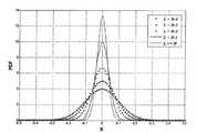
도 4는 본 발명과 관련하여, 앙상블 프레임(E)의 개수와 입사 프레임의 개수(N)의 차이에 따라 수신된 적혈구 신호의 확률 밀도 함수를 도시한다.
도 5는 본 발명에 따른 앙상블 프레임의 개수 변화에 따른 혈류 속도 추정 오차를 도시한다.
도 6은 본 발명에 따른 초음파 도플러 영상 장치의 제어 방법의 흐름도를 도시한다.
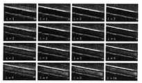
도 7은 본 발명과 관련하여, 인체 모사 팬텀에서의 총경동맥(CCA) 부분의 도플러 영상화를 수행한 결과를 도시한다.
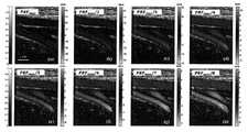
도 8은 본 발명과 관련하여, 높은 혈류 속도를 가지는 팬텀의 경동맥 분지 환경에서의 결과를 도시한다.
도 9는 본 발명에 관련하여 특정 시간 차에 따른 SCR (signal-to-clutter ratio)과 RMSVE (root mean squared velocity error) 값을 도시한 것이다.
도 10은 본 발명의 실시 예에 따른 인체 내 대퇴혈관에서의 초음파 영상을 도시한다.
도 11은 특정 시간 차이(time lag, L)의 변화에 따른 혈류 영상화 결과를 도시한다.1 shows a detailed block diagram of an ultrasonic Doppler imaging apparatus according to the present invention.
FIG. 2 shows various methods of estimating blood flow velocity through synthesis of plane waves according to a method of acquiring ultrasound data and a specific time lag (L) according to the present invention.
3 shows the maximum synthesizable frame number according to the Doppler PRF, in the context of the present invention.
4 shows a probability density function of a received erythrocyte signal according to the difference between the number of ensemble frames E and the number N of incident frames, in the context of the present invention.
FIG. 5 shows a blood flow velocity estimation error according to a change in the number of ensemble frames according to the present invention.
6 shows a flowchart of a method of controlling an ultrasonic Doppler imaging apparatus according to the present invention.
Figure 7 shows the results of performing Doppler imaging of the total carotid artery (CCA) portion in a human simulated phantom in the context of the present invention.
8 shows the results in the carotid artery branch environment of a phantom with a high blood flow velocity, in the context of the present invention.
FIG. 9 shows signal-to-clutter ratio (SCR) and root mean squared velocity error (RMSVE) values according to a specific time difference according to the present invention.
10 illustrates an ultrasound image in a femoral vein in a human body according to an embodiment of the present invention.
FIG. 11 shows blood flow imaging results according to a change in a specific time lag (L).
이하에서, 첨부된 도면을 이용하여 본 발명에 대하여 구체적으로 설명한다. 본 발명을 설명함에 있어서, 관련된 공지 기술에 대한 구체적인 설명이 본 발명의 요지를 불필요하게 흐릴 수 있다고 판단되는 경우 그 상세한 설명을 생략한다. 또한, 본 명세서의 설명 과정에서 이용되는 숫자(예를 들어, 제1, 제2 등)는 하나의 구성요소를 다른 구성요소와 구분하기 위한 식별기호에 불과하다.Hereinafter, the present invention will be described in detail with reference to the accompanying drawings. DETAILED DESCRIPTION OF THE PREFERRED EMBODIMENTS Hereinafter, the present invention will be described in detail with reference to the accompanying drawings. In addition, numerals (e.g., first, second, etc.) used in the description of the present invention are merely an identifier for distinguishing one component from another.
상술한 본 발명의 특징 및 효과는 첨부된 도면과 관련한 다음의 상세한 설명을 통하여 보다 분명해 질 것이며, 그에 따라 본 발명이 속하는 기술 분야에서 통상의 지식을 가진 자가 본 발명의 기술적 사상을 용이하게 실시할 수 있을 것이다. 본 발명은 다양한 변경을 가할 수 있고 여러가지 형태를 가질 수 있는바, 특정 실시 예들을 도면에 예시하고 본문에 상세하게 설명하고자 한다. 그러나 이는 본 발명을 특정한 개시형태에 대해 한정하려는 것이 아니며, 본 발명의 사상 및 기술범위에 포함되는 모든 변경, 균등물 내지 대체물을 포함하는 것으로 이해되어야 한다. 본 명세서에서 사용한 용어는 단지 특정한 실시 예들을 설명하기 위해 사용된 것으로, 본 발명을 한정하려는 의도가 아니다.BRIEF DESCRIPTION OF THE DRAWINGS The above and other features and advantages of the present invention will become more apparent from the following detailed description of the present invention when taken in conjunction with the accompanying drawings, It will be possible. While the invention is susceptible to various modifications and alternative forms, specific embodiments thereof are shown by way of example in the drawings and are herein described in detail. It is to be understood, however, that the invention is not intended to be limited to the particular forms disclosed, but on the contrary, is intended to cover all modifications, equivalents, and alternatives falling within the spirit and scope of the invention. The terminology used herein is for the purpose of describing particular embodiments only and is not intended to be limiting of the invention.
본 발명은 다양한 변경을 가할 수 있고 여러 가지 실시예를 가질 수 있는바, 특정 실시예들을 도면에 예시하고 상세한 설명에 구체적으로 설명하고자 한다. 그러나 이는 본 발명을 특정한 실시 형태에 대해 한정하려는 것이 아니며, 본 발명의 사상 및 기술 범위에 포함되는 모든 변경, 균등물 내지 대체물을 포함하는 것으로 이해되어야 한다.While the invention is susceptible to various modifications and alternative forms, specific embodiments thereof are shown by way of example in the drawings and will herein be described in detail. It is to be understood, however, that the invention is not to be limited to the specific embodiments, but includes all modifications, equivalents, and alternatives falling within the spirit and scope of the invention.
본 발명과 관련하여, 평면파 합성(plane-wave angle compounding)을 이용한 의료용 칼라 도플러 영상 기법은 기존의 빔 집속 방식에 비해 높은 프레임율(frame rate)을 가지며 비교적 넓은 혈류 속도 추정 범위를 제공할 수 있다. 하지만 높은 민감도의 혈류 영상을 획득하기 위하여 프레임 합성 개수를 증가시켜야 하며, 이는 필요한 입사 프레임의 개수만큼 프레임율의 저하를 가져온다. 본 발명에서는 혈류 속도의 제한 없이 높은 프레임율, 해상도, 민감도의 도플러 영상을 제공하는 방법을 제시한다.In the context of the present invention, the medical color Doppler imaging technique using plane-wave angle compounding has a higher frame rate than the conventional beam focusing method and can provide a relatively wide range of blood flow velocity estimation . However, in order to acquire a high-sensitivity blood flow image, the number of frame syntheses must be increased. This causes a decrease in the frame rate by the number of incident frames required. In the present invention, a method of providing a Doppler image with high frame rate, resolution, and sensitivity without limiting the blood flow velocity is presented.
이하 첨부된 도면을 참조하여 본 발명에 따른 새로운 평면파 합성을 이용한 초음파 도플러 영상 장치 및 그 제어 방법에 대하여 설명하면 다음과 같다.Hereinafter, an ultrasonic Doppler imaging apparatus using a new plane wave synthesis according to the present invention and a control method thereof will be described with reference to the accompanying drawings.
도 1은 본 발명에 따른 초음파 도플러 영상 장치의 상세 블록도를 도시한다. 도 1을 참조하면, 상기 초음파 도플러 영상 장치(100)는 송수신부(110), 래그 별 앙상블 프레임 생성부(120), 신호 처리부(130) 및 디스플레이부(140)를 포함한다.1 shows a detailed block diagram of an ultrasonic Doppler imaging apparatus according to the present invention. 1, the ultrasonic Doppler
송수신부(110)는 트랜스듀서(111), 펄서(112) 및 빔 포머(113)를 포함할 수 있다. 펄서(112)는 트랜스듀서(111)에 구동 신호를 공급한다. 특히, 펄서(112)는 일정한 주기로 평면파를 발생시킬 수 있다. 구체적으로, 펄서(112)는 트랜스듀서(111)에 포함된 변환 소자에 평면파 구동 신호를 공급하여 대상체로 평면파를 송신하도록 트랜스듀서(111)를 제어할 수 있다.The transceiver 110 may include a transducer 111, a pulser 112, and a beam former 113. The pulser 112 supplies a driving signal to the transducer 111. In particular, the pulsar 112 can generate plane waves at a constant period. Specifically, the pulser 112 can control the transducer 111 to supply a plane wave driving signal to the conversion element included in the transducer 111 to transmit a plane wave to the object.
또한, 서로 다른 각도를 갖는 복수의 평면파를 대상체로 송신하고자 하는 경우, 펼서(112)는 각각의 각도에 따른 지연(delay)값을 적용한 구동 신호를 통해 트랜스듀서(111)가 서로 다른 각도의 평면파를 대상체로 송신하도록 제어할 수 있다.When a plurality of plane waves having mutually different angles are to be transmitted to the object, the spreader 112 causes the transducer 111 to transmit the plane waves of different angles through the drive signal applying a delay value according to each angle, To the target object.
트랜스듀서(111)는 초음파를 대상체로 송신하고 대상체로부터 반사되는 초음파의 에코 신호를 수신한다. 트랜스듀서(111)는 전기적 신호를 음향 에너지로(또는, 반대로) 변환하는 복수의 변환 소자를 포함할 수 있다. 복수 개의 변환 소자는 1차원 어레이 형태일 수도 있고, 2차원 어레이 형태일 수도 있다.The transducer 111 transmits an ultrasonic wave to a target object and receives an echo signal of an ultrasonic wave reflected from the target object. The transducer 111 may include a plurality of conversion elements that convert an electrical signal to acoustic energy (or vice versa). The plurality of conversion elements may be in the form of a one-dimensional array or a two-dimensional array.
이를 위해, 트랜스듀서(111)는 진동하면서 압력 변화로 초음파와 전기적 신호를 상호 변환시키는 압전형 트랜스듀서(piezoelectric micromachined ultrasonic transducer, pMUT), 정전 용량의 변화로 초음파와 전기적 신호를 상호 변환시키는 정전 용량형 트랜스듀서(capacitive micromachined ultrasonic transducer, cMUT), 자기장의 변화로 초음파와 전기적 신호를 상호 변환시키는 자기형 트랜스듀서(magnetic micromachined ultrasonic transducer, mMUT), 광학적 특성의 변화로 초음파와 전기적 신호를 상호 변환시키는 광학형 초음파 검출기(Optical ultrasonic detection) 등으로 구현될 수 있다.To this end, the transducer 111 is a piezoelectric micromachined ultrasonic transducer (pMUT) that transforms ultrasonic waves and electric signals with a change in pressure while vibrating, a capacitive transducer for converting ultrasonic waves and electric signals A capacitive micromachined ultrasonic transducer (cMUT), a magnetic micromachined ultrasonic transducer (mMUT) that transforms ultrasonic waves and electrical signals with changes in the magnetic field, a transducer that converts ultrasonic and electrical signals An optical ultrasonic detector or the like.
빔 포머(113)는 초음파 신호에 대한 송신 집속 또는 수신 집속을 수행할 수 있다. 구체적으로, 빔 포머(113)는 트랜스듀서(111)가 초음파 신호를 송신할 때 구동 타이밍을 조절하여 특정 위치로 초음파 신호를 집속시킬 수 있다.The beam former 113 can perform transmission or reception focusing on an ultrasonic signal. Specifically, the beam former 113 can adjust the driving timing when the transducer 111 transmits an ultrasonic signal, and focus the ultrasonic signal to a specific position.
특히, 빔 포머(113)는 대상체에서 반사된 에코 신호가 트랜스듀서(111)에 도달하는 시간이 상이한 것을 감안하여 시간 지연을 가하고, 이를 통해 에코 신호를 집속하여 입사 프레임을 획득할 수 있다. 예를 들어, 빔 포머(113)는 트랜스듀서(111)로부터 수신되는 에코 신호를 디지털 신호로 변환시키고, 변환된 디지털 신호에 빔포밍(집속)을 수행하여 입사 프레임을 획득할 수 있다. 이와 같이 획득된 입사 프레임 데이터는 저장부(미도시)에 저장될 수도 있다.In particular, the beam former 113 applies a time delay in consideration of the fact that the time at which the echo signal reflected from the object reaches the transducer 111 is different, thereby focusing the echo signal and acquiring the incident frame. For example, the beam former 113 may convert an echo signal received from the transducer 111 into a digital signal, and perform beamforming (focusing) on the converted digital signal to obtain an incident frame. The incident frame data thus obtained may be stored in a storage unit (not shown).
한편, 송수신부(110)는 초음파 프로브로 구현될 수 있다. 이때, 트랜스듀서(111), 펄서(112) 및 빔 포머(113)가 모두 초음파 프로브에 포함될 수도 있고, 트랜스듀서(111)만 초음파 프로브의 내부에 포함되고 펄서(112) 및 빔 포머(113)는 다른 구성에 포함되어 커넥터 또는 네트워크를 통해 트랜스듀서(111)와 연결되는 형태의 구현도 가능함은 물론이다.The transceiver 110 may be implemented with an ultrasonic probe. At this time, both the transducer 111, the pulser 112, and the beam former 113 may be included in the ultrasonic probe, only the transducer 111 is included in the ultrasonic probe and the pulser 112 and the beam former 113, May be included in another configuration and connected to the transducer 111 via a connector or a network.
본 발명에서 상기 송수신부(110)는 한 세트를 이루는 가변 개수의 평면파를 순차적으로 반복하여 대상체로 송신하고, 상기 평면파가 상기 대상체에서 반사된 에코 신호를 수신하여 입사 프레임을 획득한다.In the present invention, the transceiver 110 repeatedly transmits a set number of plane waves as a set to a target object, and the plane wave receives an echo signal reflected from the target object to acquire an incident frame.
래그 별 앙상블 프레임 생성부(120)는 빔 포머(113)에서 획득된 입사 프레임을 합성하여 앙상블 프레임을 생성할 수 있다. 상기 래그 별 앙상블 프레임 생성부(120)에서의 상세 동작과 관련하여, 도 2 내지 도 3을 참조하면 다음과 같다.The ensemble frame generation unit 120 for each lag may generate an ensemble frame by combining the incident frames obtained in the beam former 113. [ The detailed operation of the ensemble frame generator 120 for each lag will be described with reference to FIG. 2 to FIG.
도 2는 본 발명에 따른 초음파 데이터 획득 방법 및 이에 따른 특정 시간 차이(time lag, L)에 따른 평면파 합성을 통한 다양한 혈류 속도 추정 원리를 도시한다.FIG. 2 shows various methods of estimating blood flow velocity through synthesis of plane waves according to a method of acquiring ultrasound data and a specific time lag (L) according to the present invention.
도 2의 (a)와 관련하여, 먼저 일정 시간 동안 기 설정된 개수의 평면파를 송신 후 수신된 프레임들이 메모리에 저장되면 추정하고자하는 혈류 속도에 대응되는 특정 시간 차이(래그) 간격으로 합성을 수행한다. 특히, 특정 시간 차이와 기설정된 입사 프레임의 개수가 같을 시 종래의 기술 방법과 같게 된다.Referring to FIG. 2 (a), first, frames are synthesized at specific time difference (lag) intervals corresponding to a blood flow velocity to be estimated if frames received after transmitting a predetermined number of plane waves for a predetermined time are stored in a memory . Particularly, when the specific time difference and the number of incident frames are the same, it becomes the same as the conventional technique.
도 2의 (b)와 관련하여, 동일한 시간 동안 얻어진 평면파 프레임 영상들로부터 특정 래그값을 두고 합성하여 얻어진 앙상블 프레임들의 위상에 따른 다양한 속도의 혈류 영상을 얻을 수 있음을 보여주고 있다. 즉, 특정 래그값이 증가함에 따라 적은 개수의 프레임 영상들을 합성할 수 있어 느린 속도의 혈류 영상을 얻을 수 있음을 보여준다.2 (b), it is shown that blood flow images of various velocities according to the phase of the ensemble frames obtained by synthesizing the plane wave frame images obtained during the same time with specific lag values can be obtained. That is, it is possible to synthesize a small number of frame images as the specific lag value increases, so that a slow-speed blood flow image can be obtained.
이와 관련하여, 상기 래그 별 앙상블 프레임 생성부(120)는 상기 평면파에 대응되는 순차적인 입사 프레임 중 특정 시간 차이 간격으로 가변 개수의 입사 프레임을 합성하여 기설정된 개수의 앙상블(ensemble) 프레임을 생성한다. 또한, 상기 래그 별 앙상블 프레임 생성부(120)는 상기 앙상블 프레임에 후속하는 다음 앙상블 프레임을 생성하는 것을 반복할 수 있다. 이때, 상기 특정 시간 차이 간격으로 가변 개수의 입사 프레임의 합성은 추정하고자 하는 혈류 속도에 기반하여 결정된다.In this regard, the lag-ensemble frame generator 120 generates a predetermined number of ensemble frames by synthesizing a variable number of incident frames at specific time difference intervals among consecutive incident frames corresponding to the plane waves . In addition, the lag-ensemble-frame generating unit 120 may repeatedly generate the ensemble frame following the ensemble frame. At this time, the synthesis of the variable number of incident frames at the specific time difference intervals is determined based on the blood flow velocity to be estimated.
상기 앙상블 프레임 생성과 관련하여, 상기 래그 별 앙상블 프레임 생성부(120)는 상기 평면파에 대응되는 순차적인 입사 프레임 중 상기 기설정된 개수의 입사 프레임을 합성하여 앙상블 프레임을 생성한다. 또한, 상기 래그 별 앙상블 프레임 생성부(120)는 상기 제1앙상블 프레임을 구성하는 상기 입사 프레임 중 상기 추정하고자 하는 혈류 속도에 대응되는 도플러 PRF(Pulse Repetition Frequency)와 연관된 시간 간격으로 상기 입사 프레임의 합성을 수행하여 상기 앙상블 프레임을 생성한다.With respect to generation of the ensemble frame, the ensemble frame generation unit 120 generates a ensemble frame by combining the incident frames of the sequential incident frames corresponding to the plane waves. In addition, the ensemble frame generator 120 for each lag may generate the incident frame at a time interval associated with a Doppler PRF (pulse repetition frequency) corresponding to the blood flow velocity to be estimated, among the incident frames constituting the first ensemble frame. And generates the ensemble frame by performing synthesis.
이와 관련하여, 본 발명에서 도플러 영상을 생성하기 위한 앙상블 프레임 생성 시 기설정된 개수의 입사 프레임을 합성하는 방법은 추정하고자 하는 혈류 속도, 즉, 도플러 PRF에 따라 특정 시간 차이(time lag,L)를 두고 반복적으로 기설정된 개수의 입사 프레임이 합성되어지며, 혈류 속도를 추정할 수 있는 도플러 PRF가 결정된다. 즉, 상기 도플러 PRF는 한 프레임의 데이터를 얻기 위해 초음파 신호를 송수신하는 시간 간격인 PRT(Pulse Repetition Time)의 역수인 최대 PRF(PRFmax)를 특정 시간 차이(time lag, L)로 나눈 값으로 아래의 수학식 1과 같이 결정될 수 있다.In this regard, in the present invention, a method of synthesizing a predetermined number of incident frames at the time of generating an ensemble frame for generating a Doppler image includes a step of calculating a time lag (L ) according to the blood flow velocity to be estimated, A predetermined number of incident frames are synthesized repeatedly, and a Doppler PRF capable of estimating a blood flow velocity is determined. That is, the Doppler PRF is a value obtained by dividing a maximum PRF (PRFmax ) which is an inverse number of a pulse repetition time (PRT), which is a time interval for transmitting and receiving ultrasonic signals, to obtain one frame of data, by a specific time difference (time lag, L) Can be determined as shown in Equation (1) below.
수학식 1

따라서 수학식 1과 같이L 값의 변화에 따라 앙상블 프레임을 생성하기 위한 기설정된 개수의 입사 프레임이 바뀌게 되며 다양한 스케일 또는 속도를 표현하는 혈류 영상화가 가능하게 된다.Therefore, as shown in Equation (1), a predetermined number of incident frames for generating an ensemble frame are changed according to the change of theL value, and blood flow imaging expressing various scales or velocities becomes possible.
또한, 본 발명에서 앙상블 프레임(E)의 개수는 프레임율(frame rate)을 결정짓는 중요한 요소로서 일정한 데이터 획득 시간 동안 최대 앙상블 프레임을 이용하여 도플러 영상화를 수행하게 된다. 이와 관련하여, 상기 앙상블 프레임의 최대 개수(Emax)는 하나의 도플러 영상 프레임을 위한 일정 데이터 획득 시간동안 얻어진 총 입사 프레임의 개수(TF), 기설정된 입사 프레임의 개수(Nangle), 및 상기 특정 시간 차이(time lag, L)을 이용하여 아래의 수학식 2와 같이 결정될 수 있다.Also, in the present invention, the number of ensemble framesE is an important factor that determines a frame rate, and Doppler imaging is performed using a maximum ensemble frame during a constant data acquisition time. In this regard, the maximum number (Emax ) of the ensemble frames is determined by the number of total incident frames (TF), the number of predetermined incident frames (Nangle ), and the total number of incident frames acquired during the predetermined data acquisition time for one Doppler image frame Can be determined as shown in Equation (2) below using a specific time lag (L).
수학식 2

한편, 상기 다음 앙상블 프레임 생성과 관련하여, 이전에 생성된 앙상블 프레임과 혈류 속도가 동일하다는 가정하에 다음과 같은 동작을 수행할 수 있다. 즉, 상기 래그 별 앙상블 프레임 생성부(120)는 상기 평면파에 대응되는 순차적인 입사 프레임을 합성하여 상기 다음 앙상블 프레임의 제1앙상블 프레임을 생성하고, 상기 다음 앙상블 프레임의 제1앙상블 프레임을 구성하는 상기 입사 프레임 중 상기 시간 간격으로 상기 입사 프레임의 합성을 수행하여 상기 다음 앙상블 프레임을 생성한다.On the other hand, with respect to generation of the ensemble frame, the following operation can be performed on the assumption that the ensemble frame generated is the same as the blood flow velocity. That is, the lag ensemble frame generation unit 120 generates a first ensemble frame of the next ensemble frame by compositing sequential incidence frames corresponding to the plane waves, and forms a first ensemble frame of the next ensemble frame And the incidence frames are synthesized at the time intervals among the incidence frames to generate the next ensemble frame.
또한, 상기 다음 앙상블 프레임 생성과 관련하여, 이전에 생성된 앙상블 프레임과 혈류 속도가 상이하다는 가정하에 다음과 같은 동작을 수행할 수 있다. 즉, 상기 래그 별 앙상블 프레임 생성부(120)는 상기 평면파에 대응되는 순차적인 입사 프레임을 합성하여 상기 다음 앙상블 프레임의 제1앙상블 프레임을 생성하고, 상기 다음 앙상블 프레임의 제1앙상블 프레임을 구성하는 상기 입사 프레임 중 상기 시간 간격과 상이한 제1시간 간격으로 상기 입사 프레임의 합성을 수행하여 상기 다음 앙상블 프레임을 생성할 수 있다. 즉, 초음파 프로브에 의해 센싱되는 신체의 부위가 변경되거나, 혈류 속도 추정 조건이 변경된 경우에는 이에 기반하여 추정하고자 하는 혈류 속도에 기반하여 입사 프레임의 합성을 위한 시간 간격을 조정할 수 있다.In addition, with respect to generation of the ensemble frame, the following operation can be performed on the assumption that the ensemble frame is different from the previously generated ensemble frame. That is, the lag ensemble frame generation unit 120 generates a first ensemble frame of the next ensemble frame by compositing sequential incidence frames corresponding to the plane waves, and forms a first ensemble frame of the next ensemble frame The incidence frame may be synthesized at a first time interval different from the time interval of the incident frames to generate the next ensemble frame. That is, when the body part sensed by the ultrasonic probe is changed or the blood flow velocity estimation condition is changed, the time interval for combining incident frames can be adjusted based on the blood flow velocity to be estimated.
한편, 도 3은 본 발명과 관련하여, 도플러 PRF에 따른 최대 합성 가능한 프레임 개수를 도시한다. 이와 관련하여, 기존의 평면파 합성 기반 도플러 영상 방법(UDI-AC)과 제안하는 방법(HDI-SAC)의 비교 그래프를 보여주고 있다. 추정하고자 하는 혈류 속도가 증가함에 따라 도플러 PRF는 함께 증가되어야 하지만 기존의 방법은 최대 합성 프레임 개수가 감소하여 해상도와 민감도의 저하를 야기 시킨다. 하지만 제안하는 방법은 추정하고자 하는 혈류 속도와 무관하게 최대 합성 프레임 개수를 유지할 수 있어 고해상도 혈류 영상화가 가능함을 보여주고 있다.3 shows the maximum number of synthesizable frames according to the Doppler PRF in the context of the present invention. In this regard, a graph of a comparison between the conventional plane wave synthesis-based Doppler imaging method (UDI-AC) and the proposed method (HDI-SAC) is shown. As the blood flow velocity to be estimated increases, the Doppler PRF must be increased together. However, the conventional method decreases the number of the maximum synthesis frames, resulting in a decrease in resolution and sensitivity. However, the proposed method shows that high - resolution blood flow imaging is possible because the maximum number of composite frames can be maintained regardless of the blood flow velocity to be estimated.
한편 전술된 앙상블 프레임(E)의 개수와 관련하여, 다음과 같은 점에 주목할 필요가 있다. 일반적인 도플러 영상화 방법에서 사용되는 앙상블 프레임의 개수(약 10개)를 이용하여 본 발명의 도플러 영상화를 수행할 시L값과 기설정된 입사 프레임의 개수N에 따라 적혈구로부터 수신된 신호의 확률 밀도 함수의 분산이 다르게 나타난다 (L=N시 종래 기술의 방법). 이와 관련하여, 도 4는 본 발명과 관련하여, 앙상블 프레임(E)의 개수와 입사 프레임의 개수(N)의 차이에 따라 수신된 적혈구 신호의 확률 밀도 함수를 도시한다. 즉, 앙상블 프레임의 개수가 감소됨에 따라 수신된 신호가 분산되는 경향을 보이고, 이에 따라 낮은 혈류 속도의 추정에는 효율적일 수 있음을 보여준다.On the other hand, with respect to the number of the ensemble frames E described above, it is necessary to pay attention to the following points. When the Doppler imaging of the present invention is performed using the number of ensemble frames (about 10) used in the general Doppler imaging method, the probability density function of the signal received from the red blood cells according to theL value and the numberN of predetermined incident frames The dispersion is different (L =N , prior art method). In this regard, FIG. 4 shows a probability density function of a received erythrocyte signal according to the difference between the number of ensemble frames E and the number N of incident frames, in the context of the present invention. That is, it is shown that as the number of ensemble frames decreases, the received signals tend to be distributed, and thus, it can be efficient to estimate a low blood flow velocity.
따라서, 본 발명에서는 기존과 같이 입사 프레임의 개수와 동일한 앙상블 프레임 개수를 사용하지 않고, 수학식 2와 같이 최대 앙상블 프레임 개수를 이용할 수 있다. 상기 수학식 2와 같이 최대 앙상블 프레임 개수에 기반하여 혈류 속도 추정을 실시한다. 이와 관련하여, 도 5는 본 발명에 따른 앙상블 프레임의 개수 변화에 따른 혈류 속도 추정 오차를 도시한다. 즉, 앙상블 길이가 충분히 큰 경우(예를 들어, 15개 이상)에는 최대 앙상블 프레임의 개수가 작은 경우에도 매우 낮은 혈류 속도 추정 오차를 보임을 알 수 있다. 이와 관련하여, 수학식 1 및 수학식 2를 이용하여 유도된 프레임 레이트는 아래의 수학식 3과 같이 결정된다.Therefore, in the present invention, the maximum number of ensemble frames can be used as in Equation (2) without using the same number of ensemble frames as the number of incident frames. The blood flow velocity estimation is performed based on the maximum ensemble frame number as in Equation (2). In this regard, FIG. 5 shows a blood flow velocity estimation error according to the number of ensemble frames according to the present invention. In other words, even when the ensemble length is sufficiently large (for example, 15 or more), even if the number of maximum ensemble frames is small, a very low blood flow velocity estimation error is shown. In this regard, the frame rate derived using Equation (1) and Equation (2) is determined as Equation (3) below.
수학식 3

한편, 신호 처리부(130)는 복조부(131), 자기 상관부(132) 및 도플러 영상 생성부(133)을 포함할 수 있다. 신호 처리부(130)는 기설정된 개수의 앙상블 프레임을 이용하여 도플러 영상을 생성할 수 있다. 여기서, 도플러 영상은 예를 들어, 혈류의 방향 및 속도를 나타내는 컬러 도플러 영상이나 혈류의 유무나 적혈구의 수를 나타내는 파워 도플러 영상을 포함할 수 있으나, 이에 한정되는 것은 아니다.The signal processing unit 130 may include a
복조부(131)는 기설정된 개수의 앙상블 프레임을 복조한다. 예를 들어, 복조부(131)는 앙상블 프레임 신호의 신호 대 잡음비를 높이기 위해 대역 통과 필터를 포함할 수 있다. 또한, 복조부(131)는 앙상블 프레임 신호에 대한 기저 대역의 동상 성분 및 이상 성분을 얻기 위해 직각 복조 과정을 수행할 수 있다. 또한, 복조부(131)는 초음파 송수신 동안 혈관벽이나 심장 근육과 같이 움직이는 조직에서 반사되는 신호 성분을 제거하기 위한 클러터 필터를 포함할 수도 있다.The
자기 상관부(132)는 복조된 앙상블 프레임에 자기 상관(auto correlation)을 적용하여 대상체의 속도, 파워, 분산 값을 산출할 수 있다. 앙상블 프레임의 기저대역 동상 및 이상 성분에 자기 상관을 적용하여 각 영상점의 속도, 파워, 분산 값을 산출하는 구체적인 내용은 도 2에서 전술한 바와 같이 본 발명의 요지와 무관하므로 설명을 생략한다.The autocorrelation unit 132 can calculate the velocity, power, and variance of the object by applying auto correlation to the demodulated ensemble frame. The details of calculating the velocity, power and variance of each image point by applying autocorrelation to baseband in-phase and out-of-phase components of the ensemble frame are not related to the gist of the present invention as described above with reference to FIG.
도플러 영상 생성부(133)는 상기 자기 상관 적용 결과를 이용하여 상기 도플러 영상을 생성한다. 즉, 자기 상관 적용 결과 산출된 대상체의 속도, 파워 및 분산 값 중 적어도 하나를 이용하여 도플러 영상을 생성할 수 있다. 또한, 디스플레이부(140)는 상기 생성된 도플러 영상을 디스플레이한다.The Doppler image generator 133 generates the Doppler image using the autocorrelation application result. That is, the Doppler image can be generated using at least one of the velocity, the power, and the variance value of the object calculated as a result of the autocorrelation application. Also, the display unit 140 displays the generated Doppler image.
한편, 전술된 초음파 도플러 영상 장치를 참조하여, 본 발명에 따른 초음파 도플러 영상 장치의 제어 방법에 대하여 살펴보면 다음과 같다. 이와 관련하여, 도 6은 본 발명에 따른 초음파 도플러 영상 장치의 제어 방법의 흐름도를 도시한다. 상기 초음파 도플러 영상 장치의 제어 방법은 입사 프레임 획득 단계(S610), 앙상블 프레임 생성 단계(S620), 다음 앙상블 프레임 생성 단계(S630) 및 도플러 영상 표시 단계(S640)를 포함한다. 한편, 상기 도플러 영상 표시 단계(S640)는 프레임 복조 단계(S641), 자기 상관 적용 단계(S642) 및 도플러 영상 생성 단계(S643)을 포함할 수 있다.Hereinafter, a method of controlling the ultrasonic Doppler imaging apparatus according to the present invention will be described with reference to the ultrasonic Doppler imaging apparatus described above. In this regard, FIG. 6 shows a flowchart of a method of controlling an ultrasonic Doppler imaging apparatus according to the present invention. The control method of the ultrasonic Doppler imaging apparatus includes an incident frame acquisition step (S610), an ensemble frame generation step (S620), a next ensemble frame generation step (S630), and a Doppler image display step (S640). Meanwhile, the Doppler image display step S640 may include a frame demodulating step S641, an autocorrelation applying step S642, and a Doppler image generating step S643.
상기 입사 프레임 획득 단계(S610)는 한 세트를 이루는 기설정된 개수의 평면파를 순차적으로 반복하여 대상체로 송신하고, 상기 평면파가 상기 대상체에서 반사된 에코 신호를 수신하여 입사 프레임을 획득한다.In the incident frame obtaining step S610, a predetermined number of plane waves constituting one set are sequentially repeatedly transmitted to a target object, and the plane wave receives an echo signal reflected from the target object to obtain an incident frame.
상기 앙상블 프레임 생성 단계(S620)는 상기 평면파에 대응되는 순차적인 입사 프레임 중 특정 시간 차이 간격으로 가변 개수의 입사 프레임을 합성하여 기설정된 개수의 앙상블(ensemble) 프레임을 생성한다. 이때, 상기 특정 시간 차이 간격으로 가변 개수의 입사 프레임의 합성은 추정하고자 하는 혈류 속도에 기반하여 결정된다.The ensemble frame generation step S620 generates a predetermined number of ensemble frames by synthesizing a variable number of incident frames at specific time difference intervals among consecutive incident frames corresponding to the plane waves. At this time, the synthesis of the variable number of incident frames at the specific time difference intervals is determined based on the blood flow velocity to be estimated.
이와 관련하여, 상기 앙상블 프레임 생성 단계(S620)는 상기 평면파에 대응되는 순차적인 입사 프레임을 합성하여 제1앙상블 프레임을 생성하는 단계; 및 상기 제1앙상블 프레임을 구성하는 상기 입사 프레임 중 상기 추정하고자 하는 혈류 속도에 대응되는 도플러 PRF(Pulse Repetition Frequency)와 연관된 시간 간격으로 상기 입사 프레임의 합성을 수행하여 상기 앙상블 프레임을 생성하는 단계를 포함할 수 있다. 이때, 상기 도플러 PRF는 한 프레임의 데이터를 얻기 위해 초음파 신호를 송수신하는 시간 간격인 PRT(Pulse Repetition Time)의 역수인 최대 PRF(PRFmax)를 특정 시간 차이(time lag, L)로 나눈 값으로, 전술된 수학식 1과 같이 결정된다. 한편, 상기 앙상블 프레임의 최대 개수(Emax)는 하나의 도플러 영상 프레임을 위한 일정 데이터 획득 시간동안 얻어진 총 입사 프레임의 개수(TF), 기설정된 입사 프레임의 개수(Nangle), 및 상기 특정 시간 차이(time lag, L)를 이용하여 전술된 수학식 2와 같이 결정된다.In this regard, the ensemble frame generation step (S620) may include generating a first ensemble frame by combining sequential incidence frames corresponding to the plane waves; And generating the ensemble frame by combining the incident frames at a time interval associated with a Doppler PRF (Pulse Repetition Frequency) corresponding to the blood flow velocity to be estimated among the incident frames constituting the first ensemble frame . The Doppler PRF is a value obtained by dividing a maximum PRF (PRFmax ), which is an inverse number of a pulse repetition time (PRT), which is a time interval for transmitting and receiving an ultrasonic signal, to obtain one frame of data, by a specific time difference , And is determined according to the above-described equation (1). The maximum number Emax of the ensemble frames is determined by the number of total incident frames TF obtained during a predetermined data acquisition time for one Doppler image frame, the number of predetermined incident frames Nangle , Is determined according to the above-described equation (2) using the difference (time lag, L).
상기 다음 앙상블 프레임 생성 단계(S630)는 상기 앙상블 프레임에 후속하는 다음 앙상블 프레임을 생성하는 단계를 반복하는 단계이다. 이와 관련하여, 상기 다음 앙상블 프레임 생성 단계(S630)는 상기 평면파에 대응되는 순차적인 입사 프레임을 합성하여 제1앙상블 프레임을 생성하는 단계; 및 상기 제1앙상블 프레임을 구성하는 상기 입사 프레임 중 상기 시간 간격으로 상기 입사 프레임의 합성을 수행하여 상기 다음 앙상블 프레임을 생성하는 단계를 포함할 수 있다.The next ensemble frame generation step (S630) is a step of repeating the step of generating a next ensemble frame following the ensemble frame. In this regard, in the next ensemble frame generation step (S630), a first ensemble frame is generated by synthesizing sequentially incident frames corresponding to the plane waves; And generating the next ensemble frame by combining the incident frames at the time intervals among the incident frames constituting the first ensemble frame.
한편, 상기 다음 앙상블 프레임 생성 단계(S630)는 상기 다음 앙상블 프레임을 생성하는 단계는, 상기 평면파에 대응되는 순차적인 입사 프레임을 합성하여 제1앙상블 프레임을 생성하는 단계; 및 상기 제1앙상블 프레임을 구성하는 상기 입사 프레임 중 상기 시간 간격과 상이한 제1시간 간격으로 상기 입사 프레임의 합성을 수행하여 상기 다음 앙상블 프레임을 생성하는 단계를 포함할 수 있다. 이때, 상기 시간 간격 및 상기 제1시간 간격은, 상기 도플러 PRF의 최대값(PRFmax)의 역수의 정수배(n/PRFmax)인 것을 특징으로 할 수 있다. 한편, 상기 정수배에 해당하는 정수값(n)은 상기 추정하고자 하는 혈류 속도에 반비례하는 것을 특징으로 할 수 있다.In the next ensemble frame generation step (S630), the generating the next ensemble frame may include generating a first ensemble frame by combining sequential incidence frames corresponding to the plane waves; And generating the next ensemble frame by synthesizing the incident frames at a first time interval different from the time interval of the incident frames constituting the first ensemble frame. In this case, the time interval and the first time interval may be an integral multiple of a reciprocal of a maximum value PRFmax of the Doppler PRF (n / PRFmax ). Meanwhile, the integer value (n) corresponding to the integral multiple may be inversely proportional to the blood flow velocity to be estimated.
상기 도플러 영상 표시 단계(S640)는 상기 기설정된 개수의 앙상블 프레임을 이용하여 도플러 영상을 생성하고, 상기 생성된 도플러 영상을 디스플레이한다. 이때, 상기 프레임 복조 단계(S641)는 상기 상기 기설정된 개수의 앙상블 프레임을 복조한다. 상기 자기 상관 적용 단계(S642)는 상기 복조된 앙상블 프레임에 자기 상관을 적용한다. 또한, 도플러 영상 생성 단계(S643)는 상기 자기 상관 적용 결과를 이용하여 상기 도플러 영상을 생성한다.The Doppler image display step S640 generates a Doppler image using the predetermined number of ensemble frames, and displays the generated Doppler image. At this time, the frame demodulating step S641 demodulates the predetermined number of ensemble frames. The autocorrelation application step (S642) applies autocorrelation to the demodulated ensemble frame. In addition, the Doppler image generation step S643 generates the Doppler image using the result of the autocorrelation application.
한편, 전술된 도 2의 실시 예를 대상으로 제안된 도플러 영상화 방법의 성능을 평가하기 위하여 인체 혈관 모사 팬텀(Vessel mimicking phantom) 시험관 실험과 인체 내(in vivo) 실험을 수행하였다. 데이터 획득을 위한 평면파 송수신 조건 중 영상의 해상도와 대조도를 결정짓는 파라미터는 표1과 같다. 더불어 평면파 합성을 위한 파라미터와 제안하는 방법을 통해 래그 별 획득 가능한 도플러 PRF는 표2와 같다.Meanwhile, in order to evaluate the performance of the Doppler imaging method proposed in the embodiment of FIG. 2 described above, a vessel mimicking phantom test tube test and an in vivo test were performed. Table 1 shows the parameters that determine the resolution and contrast of the image among the plane wave transmission and reception conditions for data acquisition. Table 2 shows the Doppler PRFs that can be acquired for each lag through the parameters for the plane wave synthesis and the proposed method.


이러한 평면파 합성을 위한 파라미터와 제안하는 방법을 이용한 팬텀(phantom) 실험의 경우 직접 제작한 stenosis 50% 경동맥 모사 팬텀이 이용되었으며, 이는 총경동맥(CCA), 내경동맥(ICA), 외경동맥(ECA)로 구성된다. 이와 관련하여, 도 7은 본 발명과 관련하여, 인체 모사 팬텀에서의 총경동맥(CCA) 부분의 도플러 영상화를 수행한 결과를 도시한다. 도 7을 참조하면, 기설정된 입사 프레임의 개수는 열 별로 1, 3, 5, 9개이며 래그별로 다양한 스케일의 혈류 영상화가 가능한 것을 확인할 수 있다.In the case of phantom experiments using the parameters for this plane wave synthesis and the proposed method, a direct stenting 50% carotid artery phantom was used, which was used for the total carotid artery (CCA), internal carotid artery (ICA), external carotid artery (ECA) . In this regard, FIG. 7 illustrates the results of performing Doppler imaging of the total carotid artery (CCA) portion in a human simulated phantom in the context of the present invention. Referring to FIG. 7, it can be seen that the number of predetermined incident frames is 1, 3, 5, and 9 for each column, and blood images of various scales can be imaged on a lag-by-lag basis.
도 8은 본 발명과 관련하여, 높은 혈류 속도를 가지는 팬텀의 경동맥 분지 환경에서의 결과를 도시한다. 본 발명에서 제안하는 방법의 도8의 (c)와 (d)가 종래의 기술인 도 8의 (a)와 (b)보다 에일리어싱이 일어나지 않으면서 높은 민감도의 고해상도 혈류 영상화가 가능함을 보여주고 있다.8 shows the results in the carotid artery branch environment of a phantom with a high blood flow velocity, in the context of the present invention. 8 (c) and 8 (d) of the method proposed by the present invention show that high-resolution, high-resolution blood flow imaging is possible without aliasing compared to the conventional techniques of FIGS. 8 (a) and 8 (b).
한편, 본 발명에서 제안하는 기술의 정량적 평가를 위하여 SCR (signal-to-clutter ratio)와 RMSVE (root mean squared velocity error)가 다음의 수학식 4, 5에 의해 측정되었다.For quantitative evaluation of the technique proposed in the present invention, the signal-to-clutter ratio (SCR) and root mean squared velocity error (RMSVE) were measured by the following equations (4) and (5).
수학식 4

수학식 5


여기서 vmax는 혈관 튜브의 가운데에서의 최대 속도를 나타내며, rp는 혈관 튜브에서 방사 방향으로의 위치, R은 튜브의 반지름을 나타낸다. 또한, n은 데이터의 샘플수를 나타낸다. 이로써 측정한 기설정된 입사 프레임의 개수(N)과 특정 시간 차이(time Lag, L)별 결과를 그래프로 나타내면 아래 도 9와 같다. 도 9는 본 발명에 관련하여 특정 시간 차에 따른 SCR (signal-to-clutter ratio)과 RMSVE (root mean squared velocity error) 값을 도시한 것이다. 도 9(a)는 SCR을 측정한 결과이며, 도 9(b)는 RMSVE를 측정한 결과이다. 도 9를 참조하면, 상기 특정 시간 차이(time Lag, L)이 증가하여도 속도 오차의 변화가 거의 없음을 알 수 있다.Where vmax is the maximum velocity in the middle of the vessel tube, rp is the position in the radial direction from the vessel tube, and R is the radius of the tube. Also, n represents the number of samples of the data. The results of the number N of incident frames and the time lag (L) are shown in FIG. 9 as a graph. FIG. 9 shows signal-to-clutter ratio (SCR) and root mean squared velocity error (RMSVE) values according to a specific time difference according to the present invention. Fig. 9 (a) shows the result of measuring the SCR, and Fig. 9 (b) shows the result of measuring the RMSVE. Referring to FIG. 9, it can be seen that there is almost no change in the speed error even when the time lag (L) increases.
인체 내 실험 데이터는 대퇴혈관을 스캔하여 획득하였으며, 그 중 천부대퇴동맥(Suprficial Femoral Artery, SFA), 심부대퇴동맥(Deep Femoral Artery, DFA), 총 대퇴정맥(Common Femoral Vein, CFV)으로 구분되어 있다. 도 10은 본 발명의 실시 예에 따른 인체 내 대퇴혈관에서의 초음파 영상을 도시한다. 즉, 도 10(a)는 동시적인 PW 스펙트로그램을 보여주고 있다. 도 10(b)-(d)는 도 10(a)에서의 순간적인 시간에 해당하는 칼라 도플러 영상을 보여주고 있으며, 심장의 수축 및 이완 시 충분한 혈역학적 정보를 제공할 수 있음을 보여주고 있다.The experimental data in the human body were obtained by scanning the femoral vein. Among them, the femoral artery (Suprficial Femoral Artery, SFA), Deep Femoral Artery (DFA) and Common Femoral Vein (CFV) have. 10 illustrates an ultrasound image in a femoral vein in a human body according to an embodiment of the present invention. That is, FIG. 10 (a) shows a simultaneous PW spectrogram. FIGS. 10 (b) - (d) show color Doppler images corresponding to the instantaneous time in FIG. 10 (a) and show that sufficient hemodynamic information can be provided in the contraction and relaxation of the heart .
한편, 도 11은 특정 시간 차이(time lag, L)의 변화에 따른 혈류 영상화 결과를 도시한다. 도 11을 참조하면, 다양한 스케일의 혈류 영상화가 가능함을 보여주는 결과로서 혈류의 정성적인 분석이 가능할 수 있음을 시사하고 있다.Meanwhile, FIG. 11 shows a blood flow imaging result according to a change of a specific time lag (L). Referring to FIG. 11, it is shown that various scales of blood flow imaging are possible, and it is possible to qualitatively analyze blood flow.
전술된 바와 같이, 본 발명에 따른 초음파 영상 장치 및 상기 초음파 영상 장치의 제어 방법에서 기술된 내용들은 상호 참조되어 활용될 수 있다.As described above, the contents described in the ultrasonic imaging apparatus according to the present invention and the control method of the ultrasonic imaging apparatus can be mutually referenced and utilized.
또한, 본 발명의 실시 예들 중 적어도 하나에 따르면, 합성 시 특정 시간 차이에 의해 낮은 혈류 속도부터 높은 혈류 속도까지 민감도의 저하 없이 고해상도 혈류 영상을 제공할 수 있다는 장점이 있다.In addition, according to at least one of the embodiments of the present invention, it is possible to provide a high-resolution blood flow image without deterioration in sensitivity from a low blood flow velocity to a high blood flow velocity due to a specific time difference during synthesis.
또한, 본 발명의 실시 예들 중 적어도 하나에 따르면, 높은 프레임율을 바탕으로 정성적, 정량적 분석이 가능하여 심혈관 질환을 평가할 때 매우 유용할 수 있다는 장점이 있다. In addition, according to at least one of the embodiments of the present invention, it is possible to perform qualitative and quantitative analysis based on a high frame rate, which is advantageous in evaluating cardiovascular diseases.
본 발명의 실시 예들 중 적어도 하나에 따르면, 프레임 율의 저하와 측정 가능한 혈류 속도의 제한 없이 높은 해상도와 민감도를 가진 초음파 도플러 영상을 얻을 수 있다는 장점이 있다.According to at least one of the embodiments of the present invention, ultrasound Doppler images with high resolution and sensitivity can be obtained without lowering the frame rate and limiting the measurable blood flow velocity.
한편, 본 발명에 따른 초음파 영상 장치 및 상기 초음파 영상 장치의 제어 방법에서 소프트웨어적인 구현에 의하면, 본 명세서에서 설명되는 절차 및 기능 뿐만 아니라 각각의 구성 요소들은 별도의 소프트웨어 모듈로도 구현될 수 있다. 상기 소프트웨어 모듈들 각각은 본 명세서에서 설명되는 하나 이상의 기능 및 작동을 수행할 수 있다. 적절한 프로그램 언어로 쓰여진 소프트웨어 어플리케이션으로 소프트웨어 코드가 구현될 수 있다. 상기 소프트웨어 코드는 메모리에 저장되고, 제어부(controller) 또는 프로세서(processor)에 의해 실행될 수 있다.Meanwhile, according to the software implementation in the ultrasound imaging apparatus and the ultrasound imaging apparatus according to the present invention, not only the procedures and functions described in the present specification but also respective components can be implemented as separate software modules. Each of the software modules may perform one or more of the functions and operations described herein. Software code can be implemented in a software application written in a suitable programming language. The software code is stored in a memory and can be executed by a controller or a processor.
100: 초음파 도플러 영상 장치 110: 송수신부
120: 래그 별 앙상블 프레임 생성부130: 신호처리부
140: 디스플레이부100: Ultrasound Doppler imaging device 110: Transmitting /
120: ensemble frame generation unit for each lag 130:
140:
Claims (17)
Translated fromKorean한 세트를 이루는 기설정된 개수의 평면파를 순차적으로 반복하여 대상체로 송신하고, 상기 평면파가 상기 대상체에서 반사된 에코 신호를 수신하여 입사 프레임을 획득하는 단계;
상기 평면파에 대응되는 순차적인 입사 프레임 중 특정 시간 차이 간격으로 가변 개수의 입사 프레임을 합성하여 기설정된 개수의 앙상블(ensemble) 프레임을 생성하는 단계;
상기 앙상블 프레임에 후속하는 다음 앙상블 프레임을 생성하는 단계를 반복하는 단계; 및
상기 기설정된 개수의 앙상블 프레임을 이용하여 도플러 영상을 생성하고, 상기 생성된 도플러 영상을 디스플레이하는 단계;를 포함하고,
상기 가변 개수의 입사 프레임의 합성을 위한 특정 시간 차이 간격은 추정하고자 하는 혈류 속도에 대응되는 도플러 PRF(Pulse Repetition Frequency)와 연관된 시간간격이고,
상기 도플러 PRF는 한 프레임의 데이터를 얻기 위해 초음파 신호를 송수신하는 시간 간격인 PRT(Pulse Repetition Time)의 역수인 최대 PRF(PRF max)를 특정 시간 차이(time lag, L)로 나눈 값인, 제어 방법.A method for controlling an ultrasonic Doppler imaging apparatus,
Repeating a predetermined number of plane waves constituting one set successively to the object, receiving the echo signal reflected from the object by the plane wave to obtain an incident frame;
Generating a predetermined number of ensemble frames by synthesizing a variable number of incident frames at specific time difference intervals among consecutive incident frames corresponding to the plane waves;
Generating a next ensemble frame subsequent to the ensemble frame; And
Generating a Doppler image using the predetermined number of ensemble frames, and displaying the generated Doppler image,
The specific time difference interval for combining the variable number of incident frames is a time interval associated with a Doppler PRF (Pulse Repetition Frequency) corresponding to a blood flow velocity to be estimated,
The Doppler PRF is a value obtained by dividing a maximum PRF (PRF max), which is an inverse number of a pulse repetition time (PRT), which is a time interval for transmitting and receiving an ultrasonic signal to obtain one frame of data, by a specific time difference (time lag, L) .
상기 다음 앙상블 프레임을 생성하는 단계는,
상기 평면파에 대응되는 순차적인 입사 프레임을 합성하여 제1앙상블 프레임을 생성하는 단계; 및
상기 제1앙상블 프레임을 구성하는 상기 입사 프레임 중 상기 시간 간격으로 상기 입사 프레임의 합성을 수행하여 상기 다음 앙상블 프레임을 생성하는 단계를 포함하는, 제어 방법.The method according to claim 1,
Wherein the generating of the ensemble frame comprises:
Generating a first ensemble frame by combining sequential incidence frames corresponding to the plane waves; And
And compositing the incidence frames at the time intervals among the incidence frames constituting the first ensemble frame to generate the next ensemble frame.
상기 다음 앙상블 프레임을 생성하는 단계는,
상기 평면파에 대응되는 순차적인 입사 프레임을 합성하여 제1앙상블 프레임을 생성하는 단계; 및
상기 제1앙상블 프레임을 구성하는 상기 입사 프레임 중 상기 시간 간격과 상이한 제1시간 간격으로 상기 입사 프레임의 합성을 수행하여 상기 다음 앙상블 프레임을 생성하는 단계를 포함하는, 제어 방법.The method according to claim 1,
Wherein the generating of the ensemble frame comprises:
Generating a first ensemble frame by combining sequential incidence frames corresponding to the plane waves; And
And compositing the incident frames at a first time interval different from the time interval of the incident frames constituting the first ensemble frame to generate the next ensemble frame.
상기 앙상블 프레임의 최대 개수(Emax)는 하나의 도플러 영상 프레임을 위한 일정 데이터 획득 시간동안 얻어진 총 입사 프레임의 개수(TF), 기설정된 입사 프레임의 개수(Nangle), 및 상기 특정 시간 차이(time lag, L)를 이용하여

Wherein the maximum number of ensemble frames (Emax ) is determined by the number of total incident frames (TF), the number of predetermined incident frames (Nangle ), and the specific time difference time lag, L)
상기 시간 간격은,
상기 도플러 PRF의 최대값(PRFmax)의 역수의 정수배(n/PRFmax)인 것을 특징으로 하는, 제어방법.The method according to claim 1,
The time interval,
(N / PRFmax ) of a reciprocal of a maximum value (PRFmax ) of the Doppler PRF.
상기 정수배에 해당하는 정수값(n)은 상기 추정하고자 하는 혈류 속도에 반비례하는, 제어방법.8. The method of claim 7,
Wherein the integer value (n) corresponding to the integral multiple is inversely proportional to the blood flow velocity to be estimated.
상기 도플러 영상을 디스플레이하는 단계는,
상기 기설정된 개수의 앙상블 프레임을 복조하는 단계;
상기 복조된 앙상블 프레임에 자기 상관을 적용하는 단계; 및
상기 자기 상관 적용 결과를 이용하여 상기 도플러 영상을 생성하는 단계;를 포함하는 것을 특징으로 하는, 제어 방법.The method according to claim 1,
Wherein the displaying the Doppler image comprises:
Demodulating the predetermined number of ensemble frames;
Applying autocorrelation to the demodulated ensemble frame; And
And generating the Doppler image using the result of the autocorrelation application.
한 세트를 이루는 가변 개수의 평면파를 순차적으로 반복하여 대상체로 송신하고, 상기 평면파가 상기 대상체에서 반사된 에코 신호를 수신하여 입사 프레임을 획득하는 송수신부;
상기 평면파에 대응되는 순차적인 입사 프레임 중 특정 시간 차이 간격으로 가변 개수의 입사 프레임을 합성하여 기설정된 개수의 앙상블(ensemble) 프레임을 생성하고, 상기 앙상블 프레임에 후속하는 다음 앙상블 프레임을 생성하는 것을 반복하는 래그 별 앙상블 프레임 생성부;
상기 기설정된 개수의 앙상블 프레임을 이용하여 도플러 영상을 생성하는 신호 처리부; 및
상기 생성된 도플러 영상을 디스플레이하는 디스플레이부를 포함하고,
상기 가변 개수의 입사 프레임의 합성을 위한 특정 시간 차이 간격은 추정하고자 하는 혈류 속도에 대응되는 도플러 PRF(Pulse Repetition Frequency)와 연관된 시간간격이고,
상기 도플러 PRF는 한 프레임의 데이터를 얻기 위해 초음파 신호를 송수신하는 시간 간격인 PRT(Pulse Repetition Time)의 역수인 최대 PRF(PRF max)를 특정 시간 차이(time lag, L)로 나눈 값인, 초음파 도플러 영상 장치.In an ultrasonic Doppler imaging device,
A transmitting / receiving unit that repeatedly transmits a set number of plane waves constituting one set to a target object, receives the echo signal reflected by the target object and acquires an incident frame;
Generating a predetermined number of ensemble frames by synthesizing a variable number of incident frames at specific time difference intervals among consecutive incident frames corresponding to the plane waves, and generating a next ensemble frame subsequent to the ensemble frame An ensemble frame generation unit for each lag;
A signal processor for generating a Doppler image using the predetermined number of ensemble frames; And
And a display unit for displaying the generated Doppler image,
The specific time difference interval for combining the variable number of incident frames is a time interval associated with a Doppler PRF (Pulse Repetition Frequency) corresponding to a blood flow velocity to be estimated,
The Doppler PRF is a value obtained by dividing a maximum PRF (PRF max), which is an inverse number of a pulse repetition time (PRT), a time interval for transmitting and receiving an ultrasonic signal to obtain one frame of data, by a specific time difference (time lag, L) Imaging device.
상기 래그 별 앙상블 프레임 생성부는,
상기 평면파에 대응되는 순차적인 입사 프레임을 합성하여 상기 다음 앙상블 프레임의 제1앙상블 프레임을 생성하고,
상기 다음 앙상블 프레임의 제1앙상블 프레임을 구성하는 상기 입사 프레임 중 상기 시간 간격으로 상기 입사 프레임의 합성을 수행하여 상기 다음 앙상블 프레임을 생성하는, 초음파 도플러 영상 장치.12. The method of claim 11,
Wherein the ensemble frame generator for each lag comprises:
Generating a first ensemble frame of the next ensemble frame by synthesizing successive incident frames corresponding to the plane wave,
Wherein the second ensemble frame is composed of the incident frames at the time intervals among the incident frames constituting the first ensemble frame of the next ensemble frame to generate the next ensemble frame.
상기 래그 별 앙상블 프레임 생성부는,
상기 평면파에 대응되는 순차적인 입사 프레임을 합성하여 상기 다음 앙상블 프레임의 제1앙상블 프레임을 생성하고,
상기 다음 앙상블 프레임의 제1앙상블 프레임을 구성하는 상기 입사 프레임 중 상기 시간 간격과 상이한 제1시간 간격으로 상기 입사 프레임의 합성을 수행하여 상기 다음 앙상블 프레임을 생성하는, 초음파 도플러 영상 장치.12. The method of claim 11,
Wherein the ensemble frame generator for each lag comprises:
Generating a first ensemble frame of the next ensemble frame by synthesizing successive incident frames corresponding to the plane wave,
Wherein the second ensemble frame generating unit combines the incident frames at a first time interval different from the time interval of the incident frames constituting the first ensemble frame of the next ensemble frame to generate the next ensemble frame.
상기 앙상블 프레임의 최대 개수(Emax)는 하나의 도플러 영상 프레임을 위한 일정 데이터 획득 시간동안 얻어진 총 입사 프레임의 개수(TF), 기설정된 입사 프레임의 개수(Nangle), 및 상기 특정 시간 차이(time lag, L)를 이용하여

Wherein the maximum number of ensemble frames (Emax ) is determined by the number of total incident frames (TF), the number of predetermined incident frames (Nangle ), and the specific time difference time lag, L)
상기 기설정된 개수의 앙상블 프레임을 복조하는 I/Q 복조부;
상기 복조된 앙상블 프레임에 자기 상관을 적용하는 자기상관부; 및
상기 자기 상관 적용 결과를 이용하여 상기 도플러 영상을 생성하는 도플러 영상 생성부를 더 포함하는, 초음파 도플러 영상 장치.12. The method of claim 11,
An I / Q demodulator for demodulating the predetermined number of ensemble frames;
An autocorrelator for applying autocorrelation to the demodulated ensemble frame; And
And a Doppler image generator for generating the Doppler image using the result of the autocorrelation application.
Priority Applications (2)
| Application Number | Priority Date | Filing Date | Title |
|---|---|---|---|
| KR1020160038418AKR101809358B1 (en) | 2016-03-30 | 2016-03-30 | Ultrasonic doppler imaging apparatus using new plane wave synthesis method and controlling method thereof |
| PCT/KR2017/000269WO2017171210A1 (en) | 2016-03-30 | 2017-01-10 | Novel ultrasonic doppler imaging device using plane wave synthesis and control method therefor |
Applications Claiming Priority (1)
| Application Number | Priority Date | Filing Date | Title |
|---|---|---|---|
| KR1020160038418AKR101809358B1 (en) | 2016-03-30 | 2016-03-30 | Ultrasonic doppler imaging apparatus using new plane wave synthesis method and controlling method thereof |
Publications (2)
| Publication Number | Publication Date |
|---|---|
| KR20170112004A KR20170112004A (en) | 2017-10-12 |
| KR101809358B1true KR101809358B1 (en) | 2017-12-14 |
Family
ID=59964796
Family Applications (1)
| Application Number | Title | Priority Date | Filing Date |
|---|---|---|---|
| KR1020160038418AActiveKR101809358B1 (en) | 2016-03-30 | 2016-03-30 | Ultrasonic doppler imaging apparatus using new plane wave synthesis method and controlling method thereof |
Country Status (2)
| Country | Link |
|---|---|
| KR (1) | KR101809358B1 (en) |
| WO (1) | WO2017171210A1 (en) |
Cited By (1)
| Publication number | Priority date | Publication date | Assignee | Title |
|---|---|---|---|---|
| KR20170054982A (en)* | 2015-11-10 | 2017-05-18 | 삼성메디슨 주식회사 | Ultrasound image apparatus and method for operating the same |
Families Citing this family (2)
| Publication number | Priority date | Publication date | Assignee | Title |
|---|---|---|---|---|
| KR102628655B1 (en)* | 2018-06-29 | 2024-01-24 | 삼성전자주식회사 | Method and device to operate radar |
| CN119247369B (en)* | 2024-12-03 | 2025-03-21 | 汉江国家实验室 | Sonar long-distance target detection method, device, equipment and readable storage medium |
Citations (2)
| Publication number | Priority date | Publication date | Assignee | Title |
|---|---|---|---|---|
| KR101406806B1 (en)* | 2011-12-27 | 2014-06-13 | 삼성메디슨 주식회사 | Ultrasound system and method for providing ultrasound image |
| KR101433032B1 (en)* | 2012-04-13 | 2014-08-21 | 서강대학교산학협력단 | Method and apparatus of producing functional flow images using plain wave |
Family Cites Families (3)
| Publication number | Priority date | Publication date | Assignee | Title |
|---|---|---|---|---|
| US6390980B1 (en)* | 1998-12-07 | 2002-05-21 | Atl Ultrasound, Inc. | Spatial compounding with ultrasonic doppler signal information |
| US20080051660A1 (en)* | 2004-01-16 | 2008-02-28 | The University Of Houston System | Methods and apparatuses for medical imaging |
| KR20090042152A (en)* | 2007-10-25 | 2009-04-29 | 주식회사 메디슨 | How to remove the effect of side lobe levels |
- 2016
- 2016-03-30KRKR1020160038418Apatent/KR101809358B1/enactiveActive
- 2017
- 2017-01-10WOPCT/KR2017/000269patent/WO2017171210A1/ennot_activeCeased
Patent Citations (2)
| Publication number | Priority date | Publication date | Assignee | Title |
|---|---|---|---|---|
| KR101406806B1 (en)* | 2011-12-27 | 2014-06-13 | 삼성메디슨 주식회사 | Ultrasound system and method for providing ultrasound image |
| KR101433032B1 (en)* | 2012-04-13 | 2014-08-21 | 서강대학교산학협력단 | Method and apparatus of producing functional flow images using plain wave |
Cited By (2)
| Publication number | Priority date | Publication date | Assignee | Title |
|---|---|---|---|---|
| KR20170054982A (en)* | 2015-11-10 | 2017-05-18 | 삼성메디슨 주식회사 | Ultrasound image apparatus and method for operating the same |
| KR102641998B1 (en) | 2015-11-10 | 2024-02-28 | 삼성메디슨 주식회사 | Ultrasound image apparatus and method for operating the same |
Also Published As
| Publication number | Publication date |
|---|---|
| KR20170112004A (en) | 2017-10-12 |
| WO2017171210A1 (en) | 2017-10-05 |
Similar Documents
| Publication | Publication Date | Title |
|---|---|---|
| JP3746115B2 (en) | Ultrasonic diagnostic equipment | |
| KR102025328B1 (en) | Apparatus and method for generating ultrasonic vector doppler image using plane wave synthesis | |
| JP5715594B2 (en) | Method and apparatus for flow parameter imaging | |
| CN104105449B (en) | Motion detection using acoustic pulse and multi-hole Doppler ultrasound | |
| JP5788229B2 (en) | Ultrasonic diagnostic equipment | |
| US4182173A (en) | Duplex ultrasonic imaging system with repetitive excitation of common transducer in doppler modality | |
| US5429137A (en) | Acoustic scan conversion method and apparatus for velocity flow | |
| JP2019535448A (en) | Method and system for filtering ultrasound image clutter | |
| CN102038522B (en) | Ultrasonic diagnosis apparatus and ultrasoinc data acquisition method | |
| JP2007525299A (en) | System and method for ECG-triggered retrospective color flow ultrasound imaging | |
| CN107049361B (en) | Sound velocity imaging using shear waves | |
| JP7304937B2 (en) | Systems and methods for performing pulse wave velocity measurements | |
| JP2007222253A (en) | Blood flow image display device | |
| EP3941358B1 (en) | Three dimensional volume flow quantification and measurement | |
| JP3093823B2 (en) | Ultrasound Doppler diagnostic device | |
| KR101652727B1 (en) | Ultrasonic doppler imaging apparatus and controlling method thereof | |
| EP1003051A2 (en) | Ultrasonic imaging apparatus | |
| KR101809358B1 (en) | Ultrasonic doppler imaging apparatus using new plane wave synthesis method and controlling method thereof | |
| JP2003275210A (en) | Method for describing spectrum strain and apparatus therefor | |
| US20210077065A1 (en) | Method and apparatus for simultaneous 4d ultrafast blood flow and tissue doppler imaging of the heart and retrieving quantification parameters | |
| US5058593A (en) | Apparatus for processing and displaying ultrasonic data | |
| KR20080060625A (en) | Ultrasound diagnosis system and method for obtaining an ultrasound image based on the movement of an object | |
| JP2004195228A (en) | Adaptive filtering in ultrasonic imaging using optimized transmission sequence | |
| US12352855B2 (en) | Time-aligned plane wave compounding of ultrasound data | |
| JP4122453B2 (en) | Ultrasonic diagnostic equipment |
Legal Events
| Date | Code | Title | Description |
|---|---|---|---|
| A201 | Request for examination | ||
| PA0109 | Patent application | Patent event code:PA01091R01D Comment text:Patent Application Patent event date:20160330 | |
| PA0201 | Request for examination | ||
| E902 | Notification of reason for refusal | ||
| PE0902 | Notice of grounds for rejection | Comment text:Notification of reason for refusal Patent event date:20170710 Patent event code:PE09021S01D | |
| PG1501 | Laying open of application | ||
| E701 | Decision to grant or registration of patent right | ||
| PE0701 | Decision of registration | Patent event code:PE07011S01D Comment text:Decision to Grant Registration Patent event date:20171124 | |
| GRNT | Written decision to grant | ||
| PR0701 | Registration of establishment | Comment text:Registration of Establishment Patent event date:20171208 Patent event code:PR07011E01D | |
| PR1002 | Payment of registration fee | Payment date:20171208 End annual number:3 Start annual number:1 | |
| PG1601 | Publication of registration | ||
| PR1001 | Payment of annual fee | Payment date:20201125 Start annual number:4 End annual number:4 | |
| PR1001 | Payment of annual fee | Payment date:20221020 Start annual number:6 End annual number:6 | |
| PR1001 | Payment of annual fee | Payment date:20231205 Start annual number:7 End annual number:7 | |
| PR1001 | Payment of annual fee |