KR101808355B1 - Imaging device - Google Patents
Imaging deviceDownload PDFInfo
- Publication number
- KR101808355B1 KR101808355B1KR1020127021181AKR20127021181AKR101808355B1KR 101808355 B1KR101808355 B1KR 101808355B1KR 1020127021181 AKR1020127021181 AKR 1020127021181AKR 20127021181 AKR20127021181 AKR 20127021181AKR 101808355 B1KR101808355 B1KR 101808355B1
- Authority
- KR
- South Korea
- Prior art keywords
- light
- transmittance
- transmission
- image
- image pickup
- Prior art date
- Legal status (The legal status is an assumption and is not a legal conclusion. Google has not performed a legal analysis and makes no representation as to the accuracy of the status listed.)
- Expired - Fee Related
Links
Images


Classifications
- G—PHYSICS
- G03—PHOTOGRAPHY; CINEMATOGRAPHY; ANALOGOUS TECHNIQUES USING WAVES OTHER THAN OPTICAL WAVES; ELECTROGRAPHY; HOLOGRAPHY
- G03B—APPARATUS OR ARRANGEMENTS FOR TAKING PHOTOGRAPHS OR FOR PROJECTING OR VIEWING THEM; APPARATUS OR ARRANGEMENTS EMPLOYING ANALOGOUS TECHNIQUES USING WAVES OTHER THAN OPTICAL WAVES; ACCESSORIES THEREFOR
- G03B35/00—Stereoscopic photography
- G03B35/08—Stereoscopic photography by simultaneous recording
- G03B35/12—Stereoscopic photography by simultaneous recording involving recording of different viewpoint images in different colours on a colour film
- H—ELECTRICITY
- H04—ELECTRIC COMMUNICATION TECHNIQUE
- H04N—PICTORIAL COMMUNICATION, e.g. TELEVISION
- H04N13/00—Stereoscopic video systems; Multi-view video systems; Details thereof
- H04N13/20—Image signal generators
- H04N13/204—Image signal generators using stereoscopic image cameras
- H04N13/207—Image signal generators using stereoscopic image cameras using a single 2D image sensor
- H04N13/214—Image signal generators using stereoscopic image cameras using a single 2D image sensor using spectral multiplexing
- G—PHYSICS
- G02—OPTICS
- G02B—OPTICAL ELEMENTS, SYSTEMS OR APPARATUS
- G02B5/00—Optical elements other than lenses
- G02B5/20—Filters
- G—PHYSICS
- G03—PHOTOGRAPHY; CINEMATOGRAPHY; ANALOGOUS TECHNIQUES USING WAVES OTHER THAN OPTICAL WAVES; ELECTROGRAPHY; HOLOGRAPHY
- G03B—APPARATUS OR ARRANGEMENTS FOR TAKING PHOTOGRAPHS OR FOR PROJECTING OR VIEWING THEM; APPARATUS OR ARRANGEMENTS EMPLOYING ANALOGOUS TECHNIQUES USING WAVES OTHER THAN OPTICAL WAVES; ACCESSORIES THEREFOR
- G03B11/00—Filters or other obturators specially adapted for photographic purposes
- G—PHYSICS
- G03—PHOTOGRAPHY; CINEMATOGRAPHY; ANALOGOUS TECHNIQUES USING WAVES OTHER THAN OPTICAL WAVES; ELECTROGRAPHY; HOLOGRAPHY
- G03B—APPARATUS OR ARRANGEMENTS FOR TAKING PHOTOGRAPHS OR FOR PROJECTING OR VIEWING THEM; APPARATUS OR ARRANGEMENTS EMPLOYING ANALOGOUS TECHNIQUES USING WAVES OTHER THAN OPTICAL WAVES; ACCESSORIES THEREFOR
- G03B35/00—Stereoscopic photography
- G03B35/08—Stereoscopic photography by simultaneous recording
- H—ELECTRICITY
- H04—ELECTRIC COMMUNICATION TECHNIQUE
- H04N—PICTORIAL COMMUNICATION, e.g. TELEVISION
- H04N13/00—Stereoscopic video systems; Multi-view video systems; Details thereof
- H04N13/20—Image signal generators
- H04N13/204—Image signal generators using stereoscopic image cameras
- H04N13/207—Image signal generators using stereoscopic image cameras using a single 2D image sensor
- H04N13/218—Image signal generators using stereoscopic image cameras using a single 2D image sensor using spatial multiplexing
- H—ELECTRICITY
- H04—ELECTRIC COMMUNICATION TECHNIQUE
- H04N—PICTORIAL COMMUNICATION, e.g. TELEVISION
- H04N23/00—Cameras or camera modules comprising electronic image sensors; Control thereof
- H04N23/10—Cameras or camera modules comprising electronic image sensors; Control thereof for generating image signals from different wavelengths
- H04N23/12—Cameras or camera modules comprising electronic image sensors; Control thereof for generating image signals from different wavelengths with one sensor only
Landscapes
- Physics & Mathematics (AREA)
- General Physics & Mathematics (AREA)
- Engineering & Computer Science (AREA)
- Multimedia (AREA)
- Signal Processing (AREA)
- Spectroscopy & Molecular Physics (AREA)
- Optics & Photonics (AREA)
- Studio Devices (AREA)
- Blocking Light For Cameras (AREA)
- Stereoscopic And Panoramic Photography (AREA)
- Testing, Inspecting, Measuring Of Stereoscopic Televisions And Televisions (AREA)
- Color Television Image Signal Generators (AREA)
Abstract
Translated fromKorean
Description
Translated fromKorean본 발명은 시차(視差)를 가진 복수의 화상을 취득하는 단안(單眼)의 3차원 촬상 기술에 관한 것이다.
The present invention relates to a monocular three-dimensional imaging technique for acquiring a plurality of images having parallax.
최근, CCD나 CMOS 등의 고체 촬상 소자(이하, '촬상 소자'라고 하는 경우가 있음)를 이용한 디지털 카메라나 디지털 무비의 고기능화, 고성능화가 괄목할 만하다. 특히 반도체 제조 기술의 진보에 의해, 고체 촬상 소자에 있어서의 화소 구조의 미세화가 진행되고 있다. 그 결과, 고체 촬상 소자의 화소 및 구동 회로의 고 집적화가 도모되어 왔다. 이 때문에, 불과 몇 년 사이에 촬상 소자의 화소수가 100만 화소 정도로부터 1000만 화소 이상으로 현저하게 증가했다. 또한, 촬상에 의해서 얻어지는 화상의 질도 비약적으로 향상되고 있다. 한편, 표시 장치에 관해서는, 박형의 액정이나 플라즈마에 의한 디스플레이에 의해, 면적을 차지하지 않고, 고해상도로 고콘트래스트의 표시가 가능하게 되어, 높은 성능이 실현되고 있다. 이러한 영상의 고품질화의 흐름은, 2차원 화상으로부터 3차원 화상으로 확산되고 있다. 최근에는, 편광 안경을 필요로 하지만, 고화질의 3차원 표시 장치가 개발되기 시작하고 있다.In recent years, it has been remarkable that a digital camera or a digital movie using a solid-state image pickup device such as a CCD or a CMOS (hereinafter referred to as an " image pickup device " Particularly, advances in semiconductor manufacturing technology have made miniaturization of the pixel structure in the solid-state image pickup device. As a result, high integration of pixels and driving circuits of solid-state image pickup devices has been promoted. For this reason, in a few years, the number of pixels of the image pickup device has increased remarkably from one million pixels to ten million pixels or more. In addition, the quality of images obtained by image pickup is remarkably improved. On the other hand, with respect to the display device, high-performance display can be realized with high resolution without occupying an area by display using thin liquid crystal or plasma. Such a flow of high-quality image is diffused from a two-dimensional image to a three-dimensional image. In recent years, polarizing glasses are required, but high-quality three-dimensional display devices are beginning to be developed.
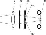
3차원 촬상 기술에 관해서, 단순한 구성을 갖는 대표적인 기술로서, 2개의 카메라로 구성되는 촬상계를 이용해서, 우안용 화상 및 좌안용 화상을 각각 취득하는 기술이 있다. 이러한, 이른바 2안 촬상 방식에서는, 카메라를 2개 이용하기 때문에, 촬상 장치가 대형으로 되고, 비용도 상승할 수 있다. 그래서, 하나의 카메라를 이용해서 시차를 가진 복수의 화상(이하, '복수 시점 화상'이라고 하는 경우가 있음)을 취득하는 방식(단안 촬상 방식)이 연구되고 있다. 예컨대, 색 필터를 이용해서 시차를 가진 2개의 화상을 동시에 취득하는 방식이 특허문헌 1에 개시되어 있다. 도 11은, 이 방식에 의한 촬상계를 모식적으로 나타내는 도면이다. 이 기술에서의 촬상계는, 렌즈(3), 렌즈 조리개(19), 투과 파장역이 다른 2개의 색 필터(20a, 20b)가 배치된 광속 제한판(20), 감광 필름(21)을 구비하고 있다. 여기서, 색 필터(20a, 20b)는, 예컨대 적색 계통, 청색 계통의 광을 각각 투과시키는 필터이다. Description of the Related Art With respect to a three-dimensional imaging technology, as a typical technique having a simple configuration, there is a technique of acquiring a right eye image and a left eye image using an imaging system composed of two cameras, respectively. In the so-called two-lens image pickup system, since two cameras are used, the size of the image pickup apparatus can be increased and the cost can be increased. Therefore, a system (monocular imaging system) for acquiring a plurality of images (hereinafter sometimes referred to as a " multi-view image ") having a time difference using one camera has been studied. For example,
이상의 구성에 의해, 입사광은, 렌즈(3), 렌즈 조리개(19) 및 광속 제한판(20)을 투과하여, 감광 필름(21)에 결상한다. 이 때, 광속 제한판(20)에 있어서의 2개의 색 필터(20a, 20b)에서는, 각각 적색 계통, 청색 계통의 광만이 투과한다. 그 결과, 감광 필름(21) 상에는 이들 2개의 색 필터를 각각 투과한 광에 의한 마젠타 계통의 색 성분의 상(像)이 형성된다. 여기서, 색 필터(20a, 20b)의 위치가 다르기 때문에, 감광 필름(21) 상에 형성되는 상에는 시차가 생긴다. 여기서, 감광 필름으로부터 사진을 만들어서, 적색 필름 및 청색 필름이 각각 우안용 및 좌안용으로서 부착된 안경을 사용하면, 깊이감이 있는 화상을 볼 수 있다. 이와 같이, 특허문헌 1에 개시된 기술에 의하면, 2개의 색 필터를 사용하여 복수 시점 화상을 만들 수 있다.With the above arrangement, the incident light passes through the
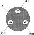
특허문헌 1에 개시된 기술은, 감광 필름 상에 결상시켜서, 시차를 가진 복수의 화상을 만드는 것이지만, 한편으로 시차를 가진 화상을 전기 신호로 변환하여 취득하는 기술이 특허문헌 2에 개시되어 있다. 도 12는, 이 기술에 있어서의 광속 제한판(22)을 모식적으로 나타내는 도면이다. 이 기술에서는, 촬상 광학계의 광축에 수직인 평면 상에, 적색광을 투과하는 R 영역(22R), 녹색광을 투과하는 G 영역(22G), 청색광을 투과하는 B 영역(22B)이 마련된 광속 제한판(22)이 이용된다. 이들 영역을 투과한 광을, 적색광을 검지하는 R 화소, 녹색광을 검지하는 G 화소, 청색광을 검지하는 B 화소를 가진 컬러 촬상 소자로 받음으로써, 각 영역을 투과한 광에 의한 화상이 취득된다.The technique disclosed in
또한, 특허문헌 3에도, 도 12의 구성과 마찬가지의 구성을 이용해서 시차를 가진 복수의 화상을 취득하는 기술이 개시되어 있다. 도 13은, 특허문헌 3에 개시된 광속 제한판(23)을 모식적으로 나타내는 도면이다. 이 기술에서도, 광속 제한판(23)에 마련된 R 영역(23R), G 영역(23G), B 영역(23B)을 입사광이 투과함으로써 시차를 가진 복수의 화상을 만들 수 있다.
특허문헌 4도 마찬가지로, 광축에 대해 대칭적으로 배치된, 서로 색이 다른 한 쌍의 필터를 이용해서 시차를 가진 복수의 화상을 생성하는 기술을 개시하고 있다. 한 쌍의 필터로서 적색 필터 및 청색 필터를 이용함으로써, 적색광을 검지하는 R 화소는 적색 필터를 투과한 광을 관측하고, 청색광을 검지하는 B 화소는 청색 필터를 투과한 광을 관측한다. 적색 필터와 청색 필터는 위치가 다르기 때문에, R 화소가 받는 광의 입사 방향과 B 화소가 받는 광의 입사 방향은 서로 다르다. 그 결과, R 화소로 관측되는 화상과 B 화소로 관측되는 화상은, 서로 시점이 다른 화상이 된다. 이들 화상으로부터 화소마다 대응점을 구함으로써, 시차량을 산출할 수 있다. 산출된 시차량과 카메라의 초점 거리 정보로부터, 카메라로부터 피사체까지의 거리가 구해진다.
특허문헌 5은, 구경 크기가 서로 다른 2장의 색 필터(예컨대, 적색과 청색)이 부착된 조리개, 또는 색이 다른 2장의 색 필터가 광축에 대해 좌우 대칭의 위치에 부착된 조리개를 이용해서 취득한 2개의 화상으로부터 피사체의 거리 정보를 구하는 기술을 개시하고 있다. 이 기술에서는, 구경 크기가 서로 다른 적색 및 청색의 색 필터를 각각 투과한 광을 관측하는 경우, 색마다 관측되는 블러의 정도가 다르다. 이 때문에, 적색 및 청색의 색 필터 각각에 대응하는 2개의 화상은, 피사체의 거리에 따라 블러의 정도가 다른 화상이 된다. 이들 화상으로부터 대응점을 구하여, 블러의 정도를 비교함으로써 카메라로부터 피사체까지의 거리 정보를 얻을 수 있다. 한편, 광축에 대해 좌우 대칭의 위치에 부착된 색이 다른 2장의 색 필터를 각각 투과한 광을 관측하는 경우, 색마다 관측되는 입사광의 방향이 다르다. 이 때문에, 적색 및 청색의 색 필터 각각에 대응하는 2개의 화상은, 시차를 가진 화상이 된다. 이들 화상으로부터 대응점을 구하여, 대응점 사이의 거리를 구함으로써, 카메라로부터 피사체까지의 거리 정보를 얻을 수 있다.
상술한 특허문헌 1~5에 개시된 기술에 의하면, 광속 제한판 또는 조리개에 RGB 계통의 색 필터를 배치함으로써 시차를 가진 복수의 화상을 생성할 수 있다. 그러나 RGB 계통의 색 필터를 이용하기 때문에, 입사광량이 크게 감소한다. 또한, 시차량을 크게 하기 위해서는 복수의 색 필터를 서로 이격된 위치에 배치하고, 이들의 면적을 작게 할 필요가 있다. 그러나 색 필터의 면적을 작게 하면 입사광량은 더욱 감소한다.According to the techniques disclosed in the above-described
이상의 종래 기술에 비해, RGB의 복수의 색 필터가 배치된 조리개를 이용해서, 시차를 가진 복수의 화상과 광량적으로 문제가 없는 통상 화상을 얻을 수 있는 기술이 특허문헌 6에 개시되어 있다. 이 기술에 의하면, 촬상 소자는 조리개를 닫은 상태에서는 RGB의 색 필터를 투과한 광만을 받고, 조리개를 연 상태에서는 RGB의 색 필터 영역이 광로로부터 벗어나기 때문에, 입사광을 모두 받을 수 있다. 이로써, 조리개를 닫은 상태에서는 복수 시점 화상을 취득하고, 조리개를 연 상태에서는 광 이용율이 높은 통상 화상을 취득할 수 있다.
특허문헌 1~5에 개시된 기술에 의하면, 복수 시점 화상을 취득할 수 있지만, 원색(RGB 계통)의 색 필터가 이용되기 때문에, 촬상 소자의 수광량은 크게 감소된다. 한편, 특허문헌 6에 개시된 기술에 의하면, 기계적 구동에 의해서 색 필터를 광로로부터 벗어나게 하는 기구를 이용해서 광 이용율이 높은 통상 화상을 취득할 수 있다. 그러나 이 기술에서도 복수 시점 화상을 취득하기 위해서는 원색의 색 필터가 사용되기 때문에, 광 이용율이 높은 복수 시점 화상은 얻을 수 없다. 또한, 이 기술에는 장치의 대형화 및 고비용화를 초래한다고 하는 과제도 있다.According to the techniques disclosed in
종래 기술에서는, 촬상 소자의 각 화소에 입사한 광의 양에 따라 생성되는 광전 변환 신호(화소 신호)를 그대로 이용해서 복수 시점 화상이 생성되고, 이들 화상간의 대응점 매칭 등을 행함으로써 거리 정보가 산출된다. 이 때문에, 원색형의 색 필터 배열을 가진 일반적인 촬상 소자를 이용하는 경우, 광속 제한판 또는 조리개에도 원색형의 색 필터를 설치할 필요가 있다. 광속 제한판 또는 조리개의 색 필터가 원색형인 경우, 각 색 필터는 자신의 투과 파장역에 포함되는 파장의 광밖에 투과시키지 않기 때문에, 유채색의 피사체를 촬영했을 때에는, 좌우의 필터를 투과하는 광의 양에 차이가 생긴다. 예컨대, 적색의 파장역의 광을 주로 반사시키는 물체를 촬영한 경우, 물체로부터 입사하는 광은 적색 필터를 투과하지만 청색 필터를 거의 투과하지 않기 때문에, 촬상 소자에 있어서의 R 화소의 화소 신호는 B 화소의 화소 신호보다 커진다. 즉, R 화소의 화소 신호로부터 생성되는 화상과 B 화소의 화소 신호로부터 생성되는 화상에서는 3차원 공간 속에서 동일한 점을 나타내는 대응점끼리이더라도 화소 신호(농담)이 크게 다르게 된다. 그 결과, 이들 2장의 화상은, 시청하는 눈의 위화감이 크고, 또한 피사체의 색이 다르면 대응점에서의 농담이 다르기 때문에, 매칭에 의한 거리 추정도 어렵게 된다. 이와 같이, 복수의 원색 필터가 배치된 조리개 또는 광속 제한판을 이용하는 종래의 기술에서는, 단색광에 가까운 광이 입사한 경우, 시차 정보를 취득할 수 없기 때문에, 적용 범위가 한정된다고 하는 과제가 있다.In the conventional technique, a plurality of view-point images are generated by using photoelectric conversion signals (pixel signals) generated in accordance with the amount of light incident on each pixel of an image pickup device, and distance information is calculated by performing corresponding point matching between these images . For this reason, when a general image pickup device having a primary color filter array is used, it is necessary to provide a primary color filter for the light flux limiting plate or diaphragm. When the color filter of the luminous flux limiting plate or diaphragm is of the primary color type, each color filter transmits only the light of the wavelength included in its transmission wavelength range. Therefore, when a subject of a chromatic color is photographed, . For example, when an object mainly reflecting light in a red wavelength region is photographed, light incident from an object passes through the red filter but does not substantially pass through the blue filter, so that the pixel signal of the R pixel in the image pickup element is B Becomes larger than the pixel signal of the pixel. That is, in an image generated from the pixel signal of the R pixel and an image generated from the pixel signal of the B pixel, pixel signals (shades) are significantly different even though corresponding points representing the same point in the three-dimensional space. As a result, in these two images, the sense of discomfort of the eyes to be watched is great, and when the colors of the subject are different, the shades at the corresponding points are different, so that it is also difficult to estimate the distance by matching. As described above, in the conventional technique using the diaphragm or the luminous flux limiting plate in which a plurality of primary color filters are arranged, there is a problem that the application range is limited because the parallax information can not be acquired when light near monochromatic light is incident.
본 발명은 기계적 구동을 행하는 일없이, 피사체로부터 입사하는 광이 단색광이라고 해도 복수 시점 화상을 취득하는 것이 가능하여, 광 이용율이 높은 복수 시점 화상을 취득할 수 있는 촬상 기술을 제공한다.
The present invention provides an imaging technique capable of acquiring a multiple viewpoint image even when the light incident from a subject is monochromatic light without performing mechanical drive and acquiring a multiple viewpoint image having a high light utilization factor.
본 발명의 3차원 촬상 장치는, 투과율의 파장 의존성이 서로 다른 m개(m은 2 이상의 정수)의 투과 영역을 갖는 광투과부와, 상기 광투과부를 투과한 광을 받도록 배치된 고체 촬상 소자로서, 광 감지 셀 어레이, 및 상기 광 감지 셀 어레이에 대향해서 배치된 투과 필터 어레이를 갖고, 상기 광 감지 셀 어레이 및 상기 투과 필터 어레이는 복수의 단위 요소로 구성되며, 각 단위 요소는 n개(n은 m 이상의 정수)의 광 감지 셀, 및 상기 n개의 광 감지 셀에 대향해서 배치된 투과율의 파장 의존성이 서로 다른 n개의 투과 필터를 포함하는, 고체 촬상 소자와, 상기 고체 촬상 소자의 촬상면에 상을 형성하는 결상부를 구비하고 있다. 파장을 λ라고 하고, 상기 m개의 투과 영역 중 임의의 2개의 투과 영역의 투과율을 나타내는 함수를 Tc1(λ) 및 Tc2(λ), 상기 n개의 투과 필터 중 임의의 2개의 투과 필터의 투과율을 나타내는 함수를 Td1(λ) 및 Td2(λ)라고 하며, 적분 구간을 가시광 전체의 파장역이라고 할 때,The three-dimensional image pickup device of the present invention is a three-dimensional image pickup device comprising: a light transmitting portion having m (m is an integer of 2 or more) transmissive regions having different transmittance wavelength dependencies; and a solid-state image pickup device arranged to receive light transmitted through the light transmitting portion, And a transmissive filter array disposed opposite to the light sensing cell array, wherein the light sensing cell array and the transmissive filter array are comprised of a plurality of unit elements, and a plurality of n transmission filters arranged to face the n light sensing cells and having different wavelength dependencies of transmittance, the solid-state image sensing device comprising: a solid-state image sensing device having an image sensing surface of the solid- And an image forming unit for forming an image. (?) And Tc2 (?) Are functions representing the transmittance of any two of the m transmission regions, and the transmittance of any two of the n transmission filters Let Td1 (lambda) and Td2 (lambda) be the functions and let the integral section be the wavelength range of the entire visible light,

일 실시예에 있어서, 상기 n개의 광 감지 셀 중 적어도 m개의 광 감지 셀로부터 출력되는 광전 변환 신호를 이용해서 상기 m개의 투과 영역에 입사한 광에 의한 m개의 복수 시점 화상을 생성하는 화상 생성부를 더 구비하고 있다.In one embodiment, an image generation unit that generates m multi-view images by light incident on the m transmission regions using photoelectric conversion signals output from at least m light sensing cells among the n light sensing cells .
일 실시예에 있어서, 상기 화상 생성부는, 각 투과 영역의 투과율 및 각 투과 필터의 투과율에 기초해서 결정되는 n행 m열의 행렬을 이용한 연산에 의해, 상기 m개의 복수 시점 화상을 생성한다.In one embodiment, the image generation unit generates the m number of viewpoint images by calculation using a matrix of n rows and m columns determined based on the transmittance of each transmittance region and the transmittance of each transmittance filter.
일 실시예에 있어서, m=2, n=2이며, 상기 화상 생성부는 ∫Tc1(λ)Td1(λ), ∫Tc1(λ)Td2(λ)dλ, ∫Tc2(λ)Td1(λ)dλ 및 ∫Tc2(λ)Td2(λ)dλ를 상기 행렬의 요소로 하는 2행 2열의 행렬을 이용해서 상기 복수 시점 화상을 생성한다.In one embodiment, m = 2 and n = 2, and the image generating unit is configured to generate the image data Dd (lambda), Dd (lambda) View image using the matrix of 2 rows and 2 columns with? Tc2 (?) Td2 (?) D? As elements of the matrix.
일 실시예에 있어서, 상기 m개의 투과 영역 중 적어도 하나에 있어서의 투과율 및 상기 n개의 투과 필터 중 적어도 하나에 있어서의 투과율은, 가시광의 파장역에서 파장 의존성을 갖지 않도록 설계되어 있다.In one embodiment, the transmittance in at least one of the m transmission regions and the transmittance in at least one of the n transmission filters are designed so that they do not have wavelength dependency in the wavelength region of visible light.
일 실시예에 있어서, 상기 m개의 투과 영역 중 적어도 하나 및 상기 n개의 투과 필터 중 적어도 하나는 투명하다.
In one embodiment, at least one of the m transmission regions and at least one of the n transmission filters are transparent.
본 발명에 의하면, 기계적 구동을 행하는 일없이, 피사체로부터 입사하는 광이 단색광이었다고 해도 복수 시점 화상을 취득할 수 있게 된다. 또한, 본 발명의 바람직한 실시예에 의하면, 종래보다 광 이용율이 높은 복수 시점 화상을 취득할 수 있게 된다.
According to the present invention, it is possible to acquire a multiple viewpoint image even if the light incident from the subject is monochromatic light, without performing mechanical driving. Further, according to the preferred embodiment of the present invention, it is possible to acquire a multi-view image having a higher light utilization factor than the conventional one.
도 1은 실시예 1에 있어서의 전체 구성을 나타내는 블록도,
도 2는 실시예 1에 있어서의 투광판, 광학계 및 촬상 소자의 개략 구성을 나타내는 모식도,
도 3은 실시예 1에 있어서의 투광판의 투과 영역의 배치를 나타내는 도면,
도 4는 실시예 1에 있어서의 촬상 소자의 투과 필터의 기본 구성을 나타내는 도면,
도 5는 투광판에 있어서의 투과 필터의 분광 투과율의 예를 나타내는 도면,
도 6은 촬상 소자에 있어서의 투과 필터의 분광 투과율이 예를 나타내는 도면,
도 7은 투광판에 있어서의 투과 필터의 분광 투과율의 다른 예를 나타내는 도면,
도 8은 촬상 소자에 있어서의 투과 필터의 분광 투과율의 다른 예를 나타내는 도면,
도 9는 m개의 투과 영역을 갖는 투광판의 일례를 나타내는 도면,
도 10은 촬상 소자의 각 단위 요소에 있어서의 n개의 색 필터의 배치의 일례를 나타내는 도면,
도 11은 특허문헌 1에 있어서의 촬상계의 구성도,
도 12는 특허문헌 2에 있어서의 광속 제한판의 외관도,
도 13은 특허문헌 3에 있어서의 광속 제한판의 외관도이다.1 is a block diagram showing the overall configuration of the first embodiment;
Fig. 2 is a schematic diagram showing a schematic configuration of a light-transmitting plate, an optical system, and an image pickup element according to
3 is a view showing the arrangement of the transmissive region of the transparent plate in Example 1,
4 is a view showing a basic configuration of a transmission filter of an image pickup device according to
5 is a view showing an example of a spectral transmittance of a transmission filter in a transparent plate,
6 is a diagram showing an example of the spectral transmittance of the transmission filter in the image pickup device,
7 is a view showing another example of the spectral transmittance of the transmission filter in the transparent plate,
8 is a view showing another example of the spectral transmittance of the transmission filter in the image pickup device,
9 is a view showing an example of a transparent plate having m number of transmissive areas,
10 is a diagram showing an example of the arrangement of n color filters in each unit element of an image pickup device,
11 is a configuration diagram of an image pickup system in
Fig. 12 is an external view of a light flux limiting plate in
Fig. 13 is an external view of a luminous flux limiting plate in
이하, 도면을 참조하면서 본 발명의 실시예를 설명한다. 이하의 설명에 있어서, 공통 또는 대응하는 요소에는 동일한 부호를 붙이고 있다. 한편, 본 명세서에 있어서, 화상을 나타내는 신호 또는 정보를 간단히 '화상'이라고 하는 경우가 있다.
Hereinafter, embodiments of the present invention will be described with reference to the drawings. In the following description, common or corresponding elements are denoted by the same reference numerals. On the other hand, in the present specification, a signal or information representing an image may be simply referred to as an " image ".
(실시예 1)(Example 1)
도 1은 본 발명의 제 1 실시예에 있어서의 촬상 장치의 전체 구성을 나타내는 블록도이다. 본 실시예의 촬상 장치는 디지털식의 전자 카메라로, 촬상부(100)와, 촬상부(100)로부터 출력되는 신호에 기초해서 화상을 나타내는 신호(화상 신호)를 생성하는 신호 처리부(200)를 구비하고 있다.1 is a block diagram showing the overall configuration of an image pickup apparatus according to a first embodiment of the present invention. The imaging apparatus of this embodiment is a digital type electronic camera and includes an
촬상부(100)는, 촬상면 상에 배열된 복수의 광 감지 셀(화소)을 구비한 촬상 소자(이미지 센서)(1)와, 투과율의 파장 의존성(분광 투과율)이 서로 다른 2개의 투과 영역을 갖는 투광판(광투과부)(2)과, 촬상 소자(1)의 촬상면 상(上)에 상(像)을 형성하기 위한 광학 렌즈(3)와, 적외 컷오프 필터(4)를 구비하고 있다. 촬상부(100)는 또한, 촬상 소자(1)를 구동하기 위한 기본 신호를 발생시킴과 아울러 촬상 소자(1)로부터의 출력 신호를 수신하여 신호 처리부(200)에 송출하는 신호 발생/수신부(5)와, 신호 발생/수신부(5)에 의해서 발생된 기본 신호에 기초해서 촬상 소자(1)를 구동하는 소자 구동부(6)를 구비하고 있다. 촬상 소자(1)는, 전형적으로는 CCD 또는 CMOS 센서로, 공지된 반도체 제조 기술에 의해서 제조된다. 신호 발생/수신부(5) 및 소자 구동부(30)는, 예컨대 CCD 드라이버 등의 LSI로 구성되어 있다.The
신호 처리부(200)는, 촬상부(100)로부터 출력된 신호를 처리하여 화상 신호를 생성하는 화상 신호 생성부(7)와, 화상 신호의 생성에 이용되는 각종의 데이터를 저장하는 메모리(30)와, 생성한 화상 신호를 외부에 송출하는 인터페이스(IF)부(8)를 구비하고 있다. 화상 신호 생성부(7)는, 공지된 디지털 신호 처리 프로세서(DSP) 등의 하드웨어와, 화상 신호 생성 처리를 포함하는 화상 처리를 실행하는 소프트웨어의 조합에 의해서 적합하게 실현될 수 있다. 메모리(30)는, DRAM 등에 의해서 구성된다. 메모리(30)는 촬상부(100)로부터 획득한 신호를 기록함과 아울러, 화상 신호 생성부(7)에 의해서 생성된 화상 데이터나, 압축된 화상 데이터를 일시적으로 기록한다. 이들 화상 데이터는, 인터페이스부(8)를 통해서 도시 생략한 기록 매체나 표시부 등에 송출된다.The
한편, 본 실시예의 촬상 장치는, 전자 셔터, 뷰 파인더, 전원(전지), 플래시라이트 등의 공지된 구성 요소를 구비할 수 있지만, 이들의 설명은 본 발명의 이해에 특별히 필요하지 않기 때문에 생략한다.On the other hand, the imaging apparatus of the present embodiment can include known components such as an electronic shutter, a viewfinder, a power source (battery), and a flashlight, but these descriptions are omitted because they are not particularly required for understanding the present invention .
다음으로, 도 2~4를 참조하면서 촬상부(100)의 구성을 보다 구체적으로 설명한다.Next, the configuration of the
도 2는 촬상부(100)에 있어서의 투광판(2), 광학 렌즈(3) 및 촬상 소자(1)의 배치 관계를 모식적으로 나타내는 도면이다. 한편, 도 2에서는 투광판(2), 광학 렌즈(3) 및 촬상 소자(1) 이외의 구성 요소는 생략되어 있다. 투광판(2)은, 분광 투과율이 서로 다른 2개의 투과 영역(C1, C2)을 갖고 입사광을 투과시킨다. 광학 렌즈(3)는 공지된 렌즈로, 투광판(2)을 투과한 광을 집광하여 촬상 소자(1)의 촬상면(1a)에 결상한다. 투광판(2)에 있어서 투과 영역(C1, C2) 이외의 영역은, 차광성 부재로 형성되어 있고, 광이 투광판(2)의 투과 영역(C1, C2) 이외는 통과하지 않도록 구성되어 있다. 이하의 설명에 있어서, 도 2에 나타낸 바와 같이, 영역(C1)으로부터 영역(C2)을 향하는 방향을 x 방향으로 하고, 촬상면(1a)에 평행한 평면 상에서 x 방향에 수직인 방향을 y 방향으로 하는 좌표를 이용한다. 한편, 도 2에 나타내는 각 구성 요소의 배치 관계는 어디까지나 일례로, 본 발명은 이러한 배치 관계로 한정되는 것이 아니다. 예컨대, 렌즈(3)는 촬상면(1a)에 상을 형성할 수 있다면 투광판(2)보다 촬상 소자(1)로부터 이격되어 배치되어 있어도 된다. 또한, 렌즈(3)와 투광판(2)이 일체로 구성되어 있어도 된다.2 is a diagram schematically showing the arrangement relationship of the
도 3은 본 실시예에 있어서의 투광판(2)의 정면도이다. 본 실시예에 있어서의 투광판(2)의 형상은, 렌즈(3)의 형상과 마찬가지로 원형이지만, 다른 형상이어도 된다. 영역(C1 및 C2)에는, 가시광 W의 파장역에 포함되는 임의의 파장의 광에 대해 그 적어도 일부를 투과시키는 투과 필터가 배치된다. 어느 투과 필터도 가시광의 파장역에 포함되는 임의의 파장의 광을 투과시키지만, 이들의 분광 투과율이 다르기 때문에, 같은 광이 영역(C1)을 통과한 경우와 영역(C2)을 통과한 경우에 투과광의 밝기(휘도)는 서로 다르다. 각 투과 영역의 분광 투과율에 대한 세부 사항은 후술한다. 한편, 각 투과 필터는, 소망의 투과율로 광을 투과시키는 기능을 갖고 있다면, 어떤 부재로 구성되어 있어도 된다. 각 투과 필터는, 예컨대, 유리, 플라스틱, 셀로판 등으로 구성될 수 있다. 한편, 본 실시예에서는, 투과 영역(C1, C2)에는 서로 분광 투과율이 다른 투과 필터가 배치되지만, 각 영역은, 소망의 분광 투과율을 가진 부재라면 무엇으로 구성되어 있어도 된다. 예컨대, 한쪽 투과 영역을 투명으로 하는 경우, 이 영역은 공기로 대용해도 된다. 여기서, '투명'이란, 가시광의 파장역에서 투과율의 파장 의존성이 없고, 광의 흡수나 산란이 발생하지 않는 상태를 의미하는 것으로 한다.3 is a front view of the
영역(C1) 및 영역(C2)은, x 방향으로 일정한 거리 L을 이격해서 배치된다. 거리 L은, 렌즈(3)의 크기에 따라, 취득되는 화상이 적절한 시차를 갖도록 결정된다. 거리 L은, 예컨대, 수 mm~수 cm로 설정될 수 있다. 투과 영역(C1, C2)은, 도 3에 나타낸 바와 같이, 광축에 대해 좌우(x 방향)로 대칭적으로 배치되며, 동일 면적을 갖고 있는 것이 바람직하다. 이 구성에 의해, 좌우의 각 영역(C1, C2)에 입사하는 광의 양이 거의 같아진다. 한편, 투과 영역(C1, C2)의 배치는, 도 3에 나타내는 배치에 한하지 않고, 용도에 따라 적절하게 결정될 수 있다. 예컨대, 상하(y 방향)의 시차 정보를 취득하려는 경우에는, 투과 영역(C1, C2)을 y 방향으로 나열해도 된다. 또한, 투과 영역(C1, C2)의 투과율의 차이가 큰 경우에는, 관측되는 화소값의 차이가 커지기 때문에, 취득되는 2개의 화상의 밝기에 차이가 생긴다. 이 때문에, 투과 영역(C1, C2)의 투과율의 차이가 큰 경우, 취득되는 2개의 화상의 밝기가 가까워지도록, 영역(C1, C2)의 면적을 조정해도 된다.The region C1 and the region C2 are arranged apart from each other by a constant distance L in the x direction. The distance L is determined in accordance with the size of the
도 2에 도시된 촬상 소자(1)의 촬상면(1a)에는, 2차원 형상으로 배열된 광 감지 셀 어레이 및 광 감지 셀 어레이에 대향하여 배치된 투과 필터 어레이가 형성되어 있다. 광 감지 셀 어레이 및 투과 필터 어레이는, 복수의 단위 요소로 구성되어 있다. 본 실시예에서는, 각 단위 요소는 2개의 광 감지 셀 및 이들에 대향하는 2개의 투과 필터를 포함하고 있다. 각 광 감지 셀은, 전형적으로는 포토다이오드를 포함하고 있고, 광전 변환에 의해서 각각의 수광량에 따른 전기 신호('광전 변환 신호' 또는 '화소 신호'라고 함)를 출력한다. 각 투과 필터는, 공지된 안료나 유전체 다층막 등을 이용해서 제작되어, 가시광의 파장역에 포함되는 임의의 파장의 광에 대하여, 적어도 일부를 투과시키도록 설계되어 있다.On the
도 4는, 본 실시예에 있어서의 투과 필터 어레이의 일부를 모식적으로 나타내는 평면도이다. 도시된 바와 같이, 촬상면(1a) 상에는 다수의 투과 필터(110)가 행렬 형상으로 배열되어 있다. 상술한 바와 같이, 근접하는 2개의 투과 필터(110) 및 이들에 대향하는 2개의 광 감지 셀(120)이 하나의 단위 요소에 포함된다. 각 단위 요소가 갖는 2개의 투과 필터(D1, D2)는 모두 가시광의 파장역에 포함되는 임의의 파장의 광을 투과시키지만, 투과율의 파장 의존성이 서로 다르다. 이들 투과 필터(D1, D2)의 투과율의 설정에 관해서는, 투광판(2)의 투과 영역(C1, C2)의 투과율과 함께 후술한다.4 is a plan view schematically showing a part of the transmission filter array in the present embodiment. As shown in the figure, on the
한편, 도 4에 나타내는 예에서는, 2개의 광 감지 셀을 옆(x 방향)으로 나열했지만, 광 감지 셀(120)의 배열은 다른 어떤 배열이어도 된다. 예컨대, 세로(y 방향)로 나열해도 되고, 비스듬하게 나열해도 된다. 또한, 하나의 단위 요소에 포함되는 광 감지 셀(120)의 수는 2개로 한하지 않고, 3개 이상이어도 된다. 또한, 광 감지 셀(120) 및 투과 필터(110)는, x 방향 및 y 방향을 따라 배열되어 있을 필요는 없고, x 방향 및 y 방향에 대해 비스듬하게 배열되어 있어도 된다.In the example shown in FIG. 4, the two light sensing cells are arranged in the lateral direction (x direction), but the arrangement of the
이상의 구성에 의해, 노광중에 촬상 장치에 입사한 광은, 투광판(2), 렌즈(3), 적외 컷오프 필터(4), 투과 필터(110)를 거쳐서 광 감지 셀(120)에 입사한다. 각 광 감지 셀은, 투광판(2)의 영역(C1, C2) 각각을 투과한 광 중 대향하는 투과 필터를 통과한 광을 받아서, 받은 광의 양에 따른 광전 변환 신호를 출력한다.The light incident on the image sensing device during exposure is incident on the
각 광 감지 셀에 의해서 출력된 광전 변환 신호는, 신호 발생/수신부(5)를 통해서 신호 처리부(200)에 송출된다. 신호 처리부(200)에 있어서의 화상 신호 생성부(7)는, 촬상부(100)로부터 송출된 신호에 기초해서 복수 시점 화상을 생성한다.The photoelectric conversion signal output by each light sensing cell is sent to the
이하, 각 광 감지 셀로부터 출력되는 광전 변환 신호를 설명한다. 투과 영역(C1, C2) 및 투과 필터(D1, D2)의 투과율이, 어떤 파장에 대해서도 100%라고 가정한 경우에, 영역(C1)을 통해서 착안하는 하나의 화소에 입사하는 광의 강도를 나타내는 신호를 Ci1, 영역(C2)을 통해서 착안하는 하나의 화소에 입사하는 광의 강도를 나타내는 신호를 Ci2로 나타내는 것으로 한다. 또한, 전제로서, 하나의 단위 요소에 포함되는 각 광 감지 셀에는 동일한 강도의 광이 입사하는 것으로 하고, 입사하는 광은 모두 가시광이라고 가정한다. 설명을 간단하게 하기 위해서, 영역(C1, C2)에 입사하는 광의 강도의 파장 의존성을 무시한다. 즉, 피사체는 무채색이라고 가정한다. 또한, 렌즈(3) 및 적외 컷오프 필터(4)를 합친 분광 투과율을 Tw, 영역(C1)의 분광 투과율을 Tc1, 영역(C2)의 분광 투과율을 Tc2로 한다. 마찬가지로, 촬상 소자(1)에 있어서의 투과 필터(D1, D2)의 분광 투과율을 각각 Td1, Td2로 나타낸다.Hereinafter, the photoelectric conversion signal output from each light sensing cell will be described. A signal indicating the intensity of light incident on one pixel of interest through the region C1 when the transmissivity of the transmissive regions C1 and C2 and the transmissive filters D1 and D2 is assumed to be 100% And a signal indicating the intensity of light incident on one of the pixels that will be observed through the region C2 is denoted by Ci2. As a premise, it is assumed that light having the same intensity is incident on each of the light sensing cells included in one unit element, and that all incident light is visible light. In order to simplify the explanation, the wavelength dependence of the intensity of the light incident on the regions C1 and C2 is ignored. That is, it is assumed that the subject is achromatic. The spectral transmittance of the
여기서, Tw, Tc1, Tc2, Td1, Td2는, 입사하는 광의 파장 λ에 의존하는 함수이기 때문에, 각각 Tw(λ), Tc1(λ), Tc2(λ), Td1(λ), Td2(λ)라고 나타낸다. 투과 필터(D1, D2)를 투과하여 그 대향하는 광 감지 셀에서 수광되는 광의 강도를 나타내는 신호를 각각 d1, d2로 나타낸다. 또한, 가시광의 파장역에서의 분광 투과율의 적분 연산을 기호 Σ로 나타내는 것으로 한다. 예컨대, 파장 λ에 대한 적분 연산 ∫Tw(λ)Tc1(λ)Td1(λ)dλ 등을, ΣTwTc1Td1등으로 나타내는 것으로 한다. 여기서, 적분은 가시광의 전체 파장역에 걸쳐서 행해지는 것으로 한다. 그러면, d1는, Ci1ΣTwTc1Td1, Ci2ΣTwTc2Td2을 합산한 결과에 비례한다. 마찬가지로, d2는, Ci1ΣTwTc1Td2, Ci2ΣTwTc2Td2을 합산한 결과에 비례한다. 이들 관계에 있어서의 비례 계수를 1이라고 하면, d1, d2는, 각각 이하의 식 1, 2로 나타낼 수 있다.Tc1 (?), Tc2 (?), Td1 (?), And Td2 (?) Since Tw, Tc1, Tc2, Td1, and Td2 are functions that depend on the wavelength? Of incident light. . Signals indicating the intensity of light transmitted through the transmission filters D1 and D2 and received by the opposite light sensing cells are denoted by d1 and d2, respectively. It should be noted that the integration calculation of the spectral transmittance at the wavelength region of the visible light is represented by the symbol Σ. For example, the integration operation? Tw (?) Tc1 (?) Td1 (?) D? With respect to the wavelength? Is expressed by? TwTc1Td1 or the like. Here, it is assumed that the integration is performed over the entire wavelength range of the visible light. Then d1 is proportional to the sum of Ci1ΣTwTc1Td1 and Ci2ΣTwTc2Td2. Similarly, d2 is proportional to the sum of Ci1ΣTwTc1Td2 and Ci2ΣTwTc2Td2. When the proportional coefficient in these relationships is 1, d1 and d2 can be expressed by the following

식 1, 2에 있어서, ΣTwTc1Td1, ΣTwTc2Td1, ΣTwTc1Td2, ΣTwTc2Td2를, 각각 Mx11, Mx12, Mx21, Mx22라고 나타내는 것으로 한다. 그러면, 식 1은, 행렬을 이용해서 이하의 식 3으로 나타낼 수 있다.In the

여기서, 식 3에 있어서의 요소 Mx11~Mx22로 이루어지는 행렬의 역행열의 요소를, iM11~iM22라고 하면, 식 3은 다음 식 4로 변형할 수 있다. 즉, 영역(C1, C2)에 입사하는 광의 강도를 나타내는 신호(Ci1, Ci2)를, 광전 변환 신호(d1, d2)를 이용해서 나타낼 수 있다.Here, if the elements of the matrix of the matrix consisting of the elements Mx11 to Mx22 in the equation (3) are iM11 to iM22, the equation (3) can be transformed into the following equation (4). That is, signals Ci1 and Ci2 indicating the intensity of light incident on the regions C1 and C2 can be represented using the photoelectric conversion signals d1 and d2.

이상의 구성에 의해, 각 화소의 입사 광량을 나타내는 신호(d1, d2)(관측 화소값)를, 투과 영역(C1, C2)에 각각 입사하는 광의 강도 신호(Ci1, Ci2)로 변환할 수 있다.With the above arrangement, the signals d1 and d2 (observation pixel values) indicating the incident light amounts of the respective pixels can be converted into light intensity signals Ci1 and Ci2 incident on the transmission regions C1 and C2, respectively.
도 1에 나타내는 화상 신호 생성부(7)는, 식 4에 기초한 신호 연산을 실행하여, 신호(Ci1, Ci2)를, 단위 요소마다 생성한다. 단위 요소마다 생성된 신호(Ci1, Ci2)는 투과 영역(C1, C2) 각각에 입사하는 광에 의해 형성되는 2개의 화상을 나타낸다. 이들 2개의 화상은, 투과 영역(C1, C2)의 위치의 차이에 기인하는 시차를 갖는다. 이와 같이, 식 4에 기초한 연산에 의해서 복수 시점 화상을 생성할 수 있다.The image
종래와 같이 투과 영역(C1, C2)이 특정한 파장의 광밖에 투과시키지 않는 경우(C1, C2에 원색의 색 필터가 배치된 경우 등), 영역(C1, C2) 중 적어도 하나의 투과 파장역에 포함되지 않는 파장의 단색광이 피사체로부터 입사하면, d1, d2 중 적어도 하나가 0이 되기 때문에, Ci1, Ci2가 구해질 수 없다. 그래서, 본 실시예에서는, 식 4에 의해 구해지는 Ci1 및 Ci2가, Ci1>0 또한 Ci2>0를 만족하도록 투과 영역(C1, C2) 및 투과 필터(D1, D2)를 구성한다. 이로써, 피사체로부터 입사하는 광이 단색광이었다고 해도 시차(좌우의 광의 강도 신호)의 취득이 가능해진다.It is preferable that at least one of the regions C1 and C2 has a transmittance wavelength range in which the transmissive regions C1 and C2 transmit only light of a specific wavelength (such as when primary color filters are arranged in C1 and C2) When monochromatic light having a wavelength not included is incident from the subject, Ci1 and Ci2 can not be obtained because at least one of d1 and d2 becomes zero. Thus, in the present embodiment, the transmission regions C1 and C2 and the transmission filters D1 and D2 are configured so that Ci1 and Ci2 obtained by
이하, 본 실시예의 촬상 장치가 대상으로 하는 장면(scene), 피사체의 조건 및 투과 영역(C1, C2), 투과 필터(D1, D2)의 분광 투과율이 만족시켜야 되는 조건을 설명한다.
Conditions under which the scene to be imaged by the image pickup apparatus of the present embodiment, the conditions of the subject, the transmission regions C1 and C2, and the spectral transmittances of the transmission filters D1 and D2 must be satisfied will be described below.
<조건 1>: 관측 화소값(d1, d2)의 조건<
본 실시예에서는, 상술한 바와 같이 투광판(2)의 투과 영역(C1, C2)의 투과율 및 촬상 소자(1)의 투과 필터(D1, D2)의 투과율은, 가시광의 파장역에 포함되는 임의의 파장의 광에 대해 0보다 큰 값을 갖는다. 이로써, 가시광의 전체 파장역에서 광량이 0이 되는 광이 입사하는 경우를 제외하면, 관측 화소값이 항상 양의 값이 된다. 따라서, 관측 화소값(d1, d2) 중 어느 하나 0가 되는 것은, 피사체의 색이 흑, 또는 장면이 어두운 경우로 한정된다.The transmissivity of the transmissive areas C1 and C2 of the
관측 화소값이 d1=d2=0(피사체 또는 촬영 장면이 완전한 흑)인 경우, 식 4에 의해, Ci1=Ci2=0이 되기 때문에, 복수 시점 화상을 얻을 수 없다. 또한, d1=0 또한 d2≠0인 경우, 식 4에 의해, Ci1=d2iMx12, Ci2=d2iMx22가 되어, Ci1>0 또한 Ci2>0이 된다. 그러나, Ci1는 Ci2의 정수배가 되기 때문에, 밝기의 차이는 있지만 시차 정보를 얻을 수 없다. d1≠0 또한 d2=0의 경우도 마찬가지이다.When the observation pixel value is d1 = d2 = 0 (the subject or the shooting scene is completely black), Ci1 = Ci2 = 0 is obtained by the expression (4). Further, when d1 = 0 and d2? 0, Ci1 = d2iMx12 and Ci2 = d2iMx22 become Ci1 > 0 and Ci2 > However, because Ci1 is an integral multiple of Ci2, parallax information can not be obtained although there is a difference in brightness. The same holds true for d1 ≠ 0 and d2 = 0.
이상의 점에서, 본 실시예의 촬상 장치가 대상으로 하는 장면에서는, 관측 화소값은 d1>0 또한 d2>0인 것이 필요한다.
In view of the above, it is necessary that the observation pixel value be d1 > 0 and d2 > 0 in a scene targeted by the image pickup apparatus of the present embodiment.
<조건 2> : 관측 화소값으로부터 복수 시점 화상 신호로 변환하는 변환 행렬의 조건≪
다음으로 투광판(2)의 투과 영역(C1, C2) 및 촬상 소자(1)의 투과 필터(D1, D2)의 분광 투과율에 따라 규정되는 변환 행렬(Mx11, Mx12, Mx21, Mx22)을 이용해서 관측 화소값(d1, d2)으로부터 복수 시점 화상 신호(Ci1, Ci2)가 구해지는 조건을 설명한다. 복수 시점 화상 신호(Ci1, Ci2)가 구해지는 기본적인 조건으로서, 식 3으로부터 식 4로 변환 가능한 것이 필요하다. 식 4을 식 3의 변수로 표현하면, 다음 식 5가 얻어진다.Next, using the conversion matrices Mx11, Mx12, Mx21 and Mx22 defined according to the spectral transmittances of the transmission regions C1 and C2 of the

식 5가 성립하기 위해서는, 행렬식이 0 이외의 값이 아니면 안 된다. 즉, 이하의 식 6을 만족해야 한다.In order for

<조건 3> : 입사광 강도 신호(Ci1, Ci2)가 취할 수 있는 범위에 관한 조건≪
신호(Ci1, Ci2)는 광의 강도를 나타내는 신호이기 때문에, Ci1>0 또한 Ci2>0을 만족시켜야 한다. 식 3에 있어서 임의의 d1, d2에 대해서, Ci1>0 또한 Ci2>0이 되는 조건을 구하기 위해서, 다음 식 변형을 행한다. 우선, 식 5의 양변에, 식 5의 우변의 2x2 행렬의 전치 행렬을 왼쪽부터 곱해서, 다음 식 7이 얻어진다.Since the signals Ci1 and Ci2 are signals indicating the intensity of light, Ci1 > 0 and Ci2 > 0 must be satisfied. In order to obtain a condition that Ci1 > 0 and Ci2 > 0 for arbitrary d1 and d2 in

식 7의 우변을 변형하면, 식 8이 얻어진다.When the right side of

식 8의 우변의 행렬은 실대칭 행렬이다. 이 실대칭 행렬을 다음 식 9에 나타낸 바와 같이 Mat로 나타낸다.The matrix on the right hand side of Eq. (8) is a real symmetric matrix. This quasi-symmetric matrix is expressed by Mat as shown in the following equation (9).

여기서, 식 8의 양변이 양이 되기 위해서는, 행렬 Mat가 정치 대칭 행렬이면 된다. 여기서, 실대칭 행렬 Mat에 대응하는 2차 형식 xT(Mat)x가 양일 때(즉, 임의의 실수 벡터 x에 대해 xT(Mat)x>0일 때), 이 대칭 행렬 Mat을 정치 대칭 행렬이라고 한다. 따라서, 행렬 Mat의 2차 형식이 양이 되는 조건을 나타냄으로써, 임의의 d1, d2에 대해, Ci1, Ci2가 양이 되는 조건을 유도할 수 있다.Here, in order for both sides of
식 9의 대칭 행렬 Mat을 2차 형식으로 나타내면, 상기 조건으로부터 다음 식 10이 얻어진다.If the symmetric matrix Mat of Equation 9 is expressed in a quadratic form, the following Equation 10 is obtained from the above conditions.

식 10을 전개하면 다음 식 11이 얻어진다.When Eq. 10 is developed, the following Eq. 11 is obtained.

임의의 d1, d2에 있어서, 식 11이 성립하기 위해서는, 다음 식 12가 성립되면 된다.For any d1 and d2, in order for Equation (11) to hold, Equation (12) may be established.

Mx12, Mx22, Mx21, Mx11은 정치인 분광 투과율의 적분값이기 때문에, 항상 양이다. 따라서, det-1<0, 즉 det<0이 되는 조건을 구하면 된다. 여기서, det=Mx11Mx22-Mx12Mx21이기 때문에, det<0가 되는 것은, 다음 식 13의 조건을 만족시킬 때이다.Since Mx12, Mx22, Mx21, and Mx11 are integral values of the spectral transmittance of the light, they are always positive. Therefore, a condition that det <-1 <0, that is, det <0 can be obtained. Here, since det = Mx11Mx22-Mx12Mx21, det <0 is satisfied when the following condition (13) is satisfied.

여기서, 각 투과 필터의 분광 투과율을 설정하여, Mx11~Mx22가 결정된 후, Mx11Mx22<Mx12Mx21를 만족시키지 않는 경우(Mx11Mx22>Mx12Mx21인 경우)에는, 행을 교체함으로써, 식 13을 만족시키도록 행렬을 변환할 수 있다. 즉, det≠0이면, 임의의 분광 투과율의 필터에 대해서, 행렬식의 행의 교체에 의해 양의 값으로 변환할 수 있다.Here, when the spectral transmittance of each transmission filter is set so that Mx11Mx22 < Mx12Mx21 is not satisfied (Mx11Mx22 > Mx12Mx21) after Mx11 to Mx22 are determined, the matrix is transformed can do. That is, if det ≠ 0, it is possible to convert a filter having an arbitrary spectral transmittance into a positive value by replacing a row of the determinant.
이상의 점에서, 신호(Ci1, Ci2)가 Ci1>0 또한 Ci2>0을 만족시키기 위해서는, det≠0이면 된다. 이것은 식 6의 조건과 같다. 따라서, 본 실시예에 있어서의 투과 영역(C1, C2) 및 투과 필터(D1, D2)의 분광 투과율은, det≠0을 만족하는 값으로 설계된다.In order to satisfy Ci1 > 0 and Ci2 > 0, the signals Ci1 and Ci2 may be det ≠ 0. This is the same as the condition of Eq. Therefore, the spectral transmittances of the transmissive areas C1 and C2 and the transmissive filters D1 and D2 in this embodiment are designed to satisfy det ≠ 0.
여기서, 식 6을 적분 기호를 이용해서 변형하면, 이하의 식 14가 얻어진다.Here, when the equation (6) is transformed by using the integral sign, the following equation (14) is obtained.

Tw(λ)는, 렌즈(3) 및 적외 컷오프 필터(4)를 합한 분광 투과율이기 때문에, 가시광의 파장역에서는, 파장 λ에 관계없이 일정하다고 생각할 수 있다. 따라서, 식 14는 다음 식 15로 변형할 수 있다.Since Tw (?) Is the spectral transmittance of the

따라서, 본 실시예에 있어서의 투과 필터(C1, C2, C3, C4)는, 식 15를 만족하도록 설계된다. 이로써, 식 4에 근거하는 연산에 의해서 화상 신호(Ci1, Ci2)를 구할 수 있다.Therefore, the transmission filters C1, C2, C3, and C4 in the present embodiment are designed to satisfy the expression (15). Thus, the image signals Ci1 and Ci2 can be obtained by the calculation based on the equation (4).
아울러, 마찬가지 논리에 의해서, 식 3에 있어서의 행렬 대신, Tw를 제거한, ∫Tc1(λ)Td1(λ)dλ, ∫Tc1(λ)Td2(λ)dλ, ∫Tc2(λ)Td1(λ)dλ, ∫Tc2(λ)Td2(λ)dλ를 요소로 하는 행렬을 이용해서 상기 연산 처리를 행해도 된다. 이 경우, Tw는 단순한 정수이기 때문에, 상기 결론에는 변함이 없다.Td1 (?) D?,? Tc1 (?) Td2 (?) D ?,? Tc2 (?) Td1 (?) Obtained by removing Tw instead of the matrix in Expression (3) d?,? Tc2 (?) Td2 (?) d? as elements. In this case, since Tw is a simple integer, the above conclusion is not changed.
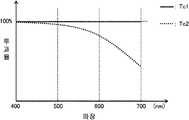
이상의 조건을 만족시키는 분광 투과율을 갖는 투과 영역(C1, C2) 및 투과 필터(D1, D2)의 예를 간단하게 설명한다. 도 5는, 투광판(2)에 있어서의 투과 영역(C1, C2)의 분광 투과율이 예를 나타내는 도면이다. 이 예에서는, 영역(C1)의 분광 투과율 Tc1은 가시광의 파장역(약 400nm~약 700nm)에서 100%가 되는 직사각형파와 같은 파형으로 나타내어지고, 영역(C2)의 분광 투과율 Tc2은 가시광의 파장역에서 cos 커브와 같은 파형으로 나타내어진다. 한편, 도 6은 촬상 소자(1)의 투과 필터(D1, D2)의 분광 투과율의 예를 나타내는 도면이다. 이 예에서는, 투과 필터 d1의 분광 투과율 Td1은 직사각형파와 같은 파형으로 나타내어지고, 투과 필터 d2의 분광 투과율 Td2은 sin 커브와 같은 파형으로 나타내어진다. 각 분광 투과율이 상기한 바와 같이 설계되어 있는 경우, ΣTc1Td1>0, ΣTc1Td2>0, ΣTc2Td1>0 및 ΣTc2Td2>0이 성립된다. 또한, Tc1 및 Td1은 어떤 파장에서도 투과율이 100%이기 때문에, 광의 감쇠가 없다. 이와 같이, 투광판(2) 및 촬상 소자(1)에 투과율이 100%가 되는 투과 영역(투과 필터)을 포함하는 구성이면, 가장 광 이용율이 좋아지기 때문에, 이러한 분광 투과율을 채용하고, 이것을 기준으로 해서 다른 분광 투과율을 설계하는 것이 바람직하다. 한편, 상기 예에서는 Tc1, Td1을 가시광의 파장역 전체에서 100%로 했지만, 엄밀하게 100% 일 필요는 없고, 예컨대 90% 이상의 투과율을 갖고 있으면, 충분히 높은 특성을 얻을 수 있다.An example of the transmissive areas (C1, C2) and the transmissive filters (D1, D2) having a spectral transmittance that satisfies the above conditions will be briefly described. Fig. 5 is a diagram showing an example of the spectral transmittance of the transmissive areas C1 and C2 in the
각 필터는, 도 5, 도 6에 나타내는 예로 한하지 않고, 가시광의 파장역에 포함되는 임의의 파장의 광에 대해서 적어도 일부를 투과시키고, Tc1와 Tc2가 서로 다르며, Td1와 Td2가 서로 다르게 설계되어 있으면 된다. 예컨대, 도 7, 도 8에 나타낸 바와 같이, Tc1, Tc2, Td1, Td2가 직사각형파나 삼각 함수 이외의 파형으로 나타내어지는 경우에도 본 발명을 적용할 수 있다.Each of the filters is not limited to the example shown in Figs. 5 and 6, and may transmit at least a part of the light of a certain wavelength included in the wavelength range of visible light. Tc1 and Tc2 may be different from each other, and Td1 and Td2 may be designed differently . For example, as shown in Figs. 7 and 8, the present invention can be applied to the case where Tc1, Tc2, Td1, and Td2 are represented by waveforms other than a rectangular wave or a trigonometric function.
상술한 소망의 분광 특성을 갖는 투과 필터는, 예컨대 유전체 다층막에 의해서 제작된다. 유전체 다층막을 이용함으로써, 예컨대 450nm, 550nm, 650nm의 파장에 투과율의 피크를 갖는 멀티 밴드패스 필터를 구성할 수 있다. 또한, 투과율이 높은 R, G, B 필터를 복수장 중첩함으로써, 투명과는 파장 의존성이 다르지만, 투과율이 높은 투과 필터를 구성하는 것이 가능하다.The transmission filter having desired spectral characteristics is fabricated, for example, by a dielectric multilayer film. By using the dielectric multilayer film, a multi-band pass filter having a peak of transmittance at a wavelength of 450 nm, 550 nm, and 650 nm, for example, can be formed. Further, by stacking a plurality of R, G, and B filters having high transmittance, a transmission filter having a high transmittance can be formed although the wavelength dependency is different from that of transparent.
이상과 같이, 본 실시예에 의하면, 투광판(2)은 2개의 투과 영역(C1, C2)을 갖고, 영역(C1, C2)에는 투과 필터가 배치되어 있다. 영역(C1, C2)은, 모두 가시광의 파장역에 포함되는 임의의 파장의 광을 투과시키지만, 이들의 투과율의 파장 의존성은 서로 다르다. 또한, 촬상 소자(1)의 광 감지 셀 어레이 및 투과 필터 어레이는 복수의 단위 요소로 구성되고, 각 단위 요소는 2개의 화소 및 이들에 대향하여 배치된 2개의 투과 필터(D1, D2)를 포함하고 있다. 투과 필터(D1, D2)에 대해서도, 모두 가시광의 파장역에 포함되는 임의의 파장의 광을 투과시키지만, 이들의 투과율의 파장 의존성은 서로 다르다. 또한, 투과 영역(C1, C2) 및 투과 필터(D1, D2)의 투과율은, 화상 신호 생성부(7)가 식 4에 근거하는 연산에 의해서 화상 신호(Ci1, Ci2)를 산출할 수 있도록, 행렬식 det≠0을 만족하도록 설계되어 있다. 이러한 구성에 의해, 입사하는 광이 가령 단색광이었다고 해도 복수 시점 화상을 생성하는 것이 가능해진다.As described above, according to the present embodiment, the
아울러, 본 실시예의 촬상 장치는, 촬상에 의해서 얻어지는 광전 변환 신호로부터 신호 연산에 의해서 화상 신호를 생성하지만, 신호 연산에 의한 화상 신호의 생성 처리를 촬상 장치와는 독립된 다른 장치에 실행시켜도 된다. 예컨대, 본 실시예에 있어서의 촬상부(100)를 가진 촬상 장치에 의해서 취득한 신호를 다른 장치에 판독시켜서, 상술한 신호 연산 처리를 규정하는 프로그램을 상기 다른 장치에 실행시키는 것에 의해서도 본 실시예와 같은 효과를 얻을 수 있다.
In addition, the image pickup apparatus of the present embodiment may generate an image signal by a signal operation from a photoelectric conversion signal obtained by image pickup, but the image signal generation processing by signal operation may be executed by another apparatus independent of the image pickup apparatus. For example, by reading a signal acquired by the image pickup apparatus having the
(실시예 2)(Example 2)
다음으로 본 발명의 실시예 2를 설명한다.Next, a second embodiment of the present invention will be described.
실시예 1의 촬상 장치에서는, 투광판(2)은 투과율의 파장 의존성이 서로 다른 2개의 투과 필터를 갖고, 촬상 소자(1)의 각 단위 요소도 마찬가지로 투과율의 파장 의존성이 서로 다른 2개의 투과 필터를 갖고 있다. 그러나 본 발명은 이러한 실시예로 한정되는 것이 아니다. 투광판(2) 및 촬상 소자(1)의 각 단위 요소는, 3개 이상의 투과 필터를 갖고 있어도 되고, 이들의 수가 달라도 된다. 이하, 실시예 1의 구성을 일반화하여, 투광판(2)에 m개(m은 2 이상의 정수)의 투과 필터가 배치되고, 촬상 소자(1)의 각 단위 요소에 n개(n은 m 이상의 정수)의 투과 필터가 배치된 구성예를 설명한다. 본 실시예의 촬상 장치는, 투광판(2) 및 촬상 소자(1)의 구성과, 화상 신호 생성부(7)에서의 처리를 제외하면 실시예 1과 같다. 이하의 설명에서는, 실시예 1과 다른 점을 중심으로 설명하며, 중복하는 사항에 대한 설명을 생략한다.In the image pickup apparatus of the first embodiment, the
도 9는, 본 실시예에 있어서의 투광판(2)의 구성예를 모식적으로 나타내는 도면이다. 본 실시예에 있어서의 투광판(2)은, m개의 투과 영역(C1, C2, … , Cm)을 갖고 있고, 각 투과 영역에는 투과 필터가 배치되어 있다. m개의 투과 영역(C1~Cm)은 모두 가시광의 파장역에 포함되는 임의의 파장의 광을 투과시키도록 설계되고, 이들의 투과율의 파장 의존성은 서로 다르다. 투광판(2) 중 m개의 투과 필터가 배치된 영역 이외에는, 광을 투과시키지 않는 차광 영역이다. 한편, 도 9의 구성에서는, 각 투과 영역은 원형이며 모두 동일한 면적을 갖고 있는 것처럼 도시되어 있지만, 각 투과 영역의 형상 및 크기는 이 예로 한정되는 것이 아니다. 또한, 각 투과 영역의 배치도 도시되는 예로 한정하지 않고, 어떠한 배치이어도 된다. 투광판(2)의 형상에 대해서도 마찬가지로, 원형일 필요는 없다. 또한, 본 실시예에서는 차광 영역을 갖고 있지만, 차광 영역의 부분을 투광성 부재로 형성하고, 이 영역도 투과 영역으로서 취급해도 된다.9 is a diagram schematically showing an example of the configuration of the
도 10은 본 실시예에 있어서의 촬상 소자(1)의 각 단위 요소(40)에 포함되는 n개의 투과 필터의 배치예를 모식적으로 나타내는 도면이다. 촬상 소자(1)의 각 단위 요소(40)는, n개의 광 감지 셀 및 이들에 대향하는 n개의 투과 필터를 갖고 있다. n개의 투과 필터 D1, D2, …, Dn은 모두 가시광의 파장역에 포함되는 임의의 파장의 광을 투과시키도록 설계되고, 이들의 투과율의 파장 의존성은 서로 다르다. 한편, 도 10에 나타내는 배열은 어디까지나 일례로, 단위 요소(40) 내의 화소배열은 다른 배열이어도 된다.10 is a diagram schematically showing an example of arrangement of n pieces of transmission filters included in each
이상의 구성에 있어서, 촬상 소자(1)의 투과 필터 D1, D2, …, Dn로부터 출력되는 화소 신호를 각각 d1, d2, …, dn이라고 한다. 또한, 투과 영역(C1~Cm) 및 투과 필터(d1~Dn)의 투과율이 100%라고 가정한 경우에 투과 영역(C1, C2, …, Cm)으로부터 각 광 감지 셀에 입사하는 광의 강도를 나타내는 신호를 각각 Ci1, Ci2, …, Cim이라고 한다. 그러면, 화소 신호(d1, d2, …, dn)과 화상 신호(Ci1, Ci2, …, Cim)의 관계는 다음 식 16으로 나타내어 진다.In the above configuration, the transmission filters D1, D2, ... of the

식 16에 있어서 각 요소가 양(正) , 또한 행렬식 det≠0이라면 투광판(2)의 각 투과 필터로부터 입사하는 광의 강도를 구할 수 있다. 실시예 1과 마찬가지로 투광판(2)의 각 투과 영역 및 촬상 소자(1)의 각 투과 필터는, 가시광의 파장역에 포함되는 임의의 파장의 광을 투과시키도록 구성되어 있기 때문에, 화소 신호(d1~dn)에 기초해서, 투광판(2)의 각 투과 영역에 입사한 광에 의한 화상 신호(Ci1~Cin)을 산출할 수 있다.The intensity of light incident from each transmission filter of the
이하, 화상 신호(Ci1~Cin)을 취득하기 위한 연산에 필요한 역행열을 구할 수 있는 조건을 설명한다. 우선, m>n인 경우, 독립된 식이 n개 밖에 없기 때문에, Ci1~Cim을 구할 수는 없다. 즉, 행렬의 랭크가 m보다 작아지기 때문에, 식 16의 해를 얻을 수 없다. 한편, n≥m인 경우에는, 독립된 식이 m개 이상 존재하면 해를 얻을 수 있다. 따라서, 행렬의 랭크가 m이 되는 독립된 식을 n'개(m≤n'≤n) 선택하면, 최소 제곱법에 의해 해를 얻을 수 있다.Hereinafter, conditions for obtaining the backward trains necessary for the calculation for acquiring the image signals Ci1 to Cin will be described. First, when m> n, Ci1 to Cim can not be obtained because there are only n independent expressions. That is, since the rank of the matrix becomes smaller than m, the solution of Expression 16 can not be obtained. On the other hand, in the case of n? M, a solution can be obtained when m or more independent expressions exist. Therefore, if n '(m? N'? N) independent expressions in which the rank of the matrix is m are selected, the solution can be obtained by the least squares method.
식 16에 있어서의 행렬과 같이 다차원의 행렬에 있어서도 행렬식 det≠0이면 랭크가 m이 되기 때문에, 행렬식의 값에 기초해서 해를 산출할 수 있는지 여부를 판정할 수 있다. 또한, 랭크를 계산하는 방법은 그 밖에도 있어, 예컨대 고유값 해석(주성분 분석이나 특이값 분해, QR 분해 등)에 의해서 얻어지는 고유값 중 값이 0이 아닌 것의 개수가 랭크가 된다. 따라서, 행렬의 고유값 해석에 의해서 얻어지는 고유값 중 값이 0이 아닌 것의 개수가 m인 것도 상기 조건(det≠0)과 같은 값이다. 한편, n>m인 경우에는, 식 16에 있어서의 행렬(이것을 A라고 한다)와 A의 전치 행렬(At)과의 고유값이 같다는 점에서, A와 At를 곱해서 정방 행열로 한 후에, 고유값 해석을 행함으로써 랭크의 계산이 가능하다.Also in the matrix of the multi-dimensional matrix like the matrix in the expression 16, since the rank is m when the matrix det ≠ 0, it can be judged whether or not the solution can be calculated based on the value of the matrix expression. In addition, there are other methods of calculating the rank. For example, the number of eigenvalues obtained by the eigenvalue analysis (principal component analysis, singular value decomposition, QR decomposition, etc.) is not zero is a rank. Therefore, it is also equal to the above condition (det? 0) that the number of eigenvalues obtained by the eigenvalue analysis of the matrix is not zero. On the other hand, in the case of n > m, the matrix is multiplied by A and At so that the matrix has the same eigenvalue as the matrix A (referred to as A) and the transpose matrix At of A , It is possible to calculate the rank by performing eigenvalue analysis.
여기서, 파장을 λ라고 하고, 투광판(2)의 m개의 투과 필터 중 임의의 2개의 투과 필터의 투과율을 Tc1(λ), Tc2(λ)로 나타내며, 촬상 소자(1)의 각 단위 요소에 포함되는 n개의 투과 필터 중 임의의 2개의 투과 필터의 투과율을 Td1(λ), Td2(λ)라고 나타낸다. 본 실시예에 있어서의 각 투과 필터는 ∫Tc1(λ)Td1(λ)dλ>0, ∫Tc1(λ)Td2(λ)dλ>0, ∫Tc2(λ)Td1(λ)dλ>0, ∫Tc2(λ)Td2(λ)dλ>0를 만족하도록 설계된다. 또한, 각 투과 필터는, 이하의 식 17을 만족하도록 설계된다.Here, the wavelength is represented by?, The transmittance of any two of the m transmission filters of the

단, 적분 구간은 가시광 전체의 파장역이다. 이상의 조건을 만족함으로써 식 14에 기초해서 화상 신호 Ci1~Cim를 구할 수 있다.However, the integral section is the wavelength range of the entire visible light. By satisfying the above conditions, the image signals Ci1 to Cim can be obtained based on the equation (14).
한편, 본 실시예의 촬상 장치는, 신호 Ci1~Cim 모두를 생성하지 않고, 이들의 신호 중 적어도 2개의 신호를 생성하도록 구성되어 있어도 된다. 이와 같은 구성이어도, 시차를 가진 적어도 2개의 화상 데이터를 얻을 수 있다. 또한, n개의 화소 신호 모두를 이용하는 것이 아니고, 행렬의 랭크가 m이 되도록 m개의 화소 신호를 선택해서 이용함으로써 m개의 복수 시점 화상을 생성해도 된다.On the other hand, the imaging apparatus of the present embodiment may be configured to generate at least two signals among these signals without generating all of the signals Ci1 to Cim. Even in such a configuration, at least two image data having parallax can be obtained. Furthermore, m number of viewpoint images may be generated by selecting and using m pixel signals so that the rank of the matrix is m instead of using all n pixel signals.
본 실시예에 있어서, m개의 투과 영역 중 적어도 하나 및 n개의 투과 필터 중 적어도 하나는, 파장 의존성이 없는 필터이어도 된다. 특히, 광 이용율을 높인다는 관점에서는, 이들은 투명한 것이 바람직하다.In the present embodiment, at least one of the m transmission regions and at least one of the n transmission filters may be a filter having no wavelength dependence. In particular, from the viewpoint of increasing the light utilization factor, they are preferably transparent.
마지막으로, 이상의 각 실시예의 촬상 장치에 있어서, 관측 화소값으로부터 복수의 입사광 강도를 산출할 때의, 해 산출의 안정성에 대해서 설명한다. 한편, 이하에서는 실시예 1의 구성을 상정하지만, 실시예 2와 같이 일반화된 구성이어도 마찬가지의 논리가 성립된다. 우선, 식 5를 노이즈를 고려해서 다시 정식화한다. 여기서, 관측 화소값(d1, d2) 각각에 부가되는 노이즈량을 Δd1, Δd2라고 한다. 노이즈로는, 화상의 열 잡음, 전송로나 촬상 소자의 산탄 노이즈 등에 더해서, 분광 투과율의 측정 오차 등도 포함될 수 있다. 이 때, 식 5는 다음 식 18, 19로 변형된다.Finally, in the image pickup apparatus of each of the above embodiments, the stability of solution calculation when calculating a plurality of incident light intensities from the observed pixel values will be described. On the other hand, although the configuration of the first embodiment is assumed below, the same logic is established even if the configuration is generalized as in the second embodiment. First,

여기서, det는 행렬식이고, det=Mx11Mx22-Mx12Mx21이다. 식 18에 있어서의 원신호 d1, d2에 관한 항을 좌변으로 이항하면, 다음 식 20이 얻어진다.Here, det is a determinant and det = Mx11Mx22-Mx12Mx21. If the term relating to the original signals d1 and d2 in Equation 18 is shifted to the left side, the following

식 20은 오차를 나타내며, 노이즈가 없다면 0이 될 것이다. 우변의 노이즈량은, 촬상 소자(1)에 기인하는 것은 신호량에 비례하고, 분광 투과율의 측정 오차에 기인하는 것은 일정한 오프셋이 된다. 어느 노이즈량이 많을지는 촬영 환경에 의존하기 때문에, 여기서는 간단히 (Mx22Δd1-Mx12Δd2)=N이라고 해 둔다. 이로써, 다음 식 21이 얻어진다.

식 21로부터, 오차는 행렬식에 반비례한다는 것을 알 수 있다. 즉, 행렬식의 절대값이 작을수록 오차의 영향이 크고, 행렬식의 절대값이 클수록 오차의 영향은 작다. 이상의 점에서, 노이즈량의 측정은 곤란하지만, |det|=|Mx11Mx22-Mx12Mx21|가 가능한 한 커지도록 각 투과 필터의 분광 투과율을 설계함으로써 노이즈에 완건한 촬상 장치를 구축할 수 있다. 예컨대, 카메라의 감도를 ISO100으로 설정하고, 형광등 아래에서 촬영하는 경우는, 행렬식의 절대값이 0.1 이상이면 안정되게 해를 얻을 수 있다는 것이 경험적으로 밝혀져 있다. 이러한 조건하에서 사용하는 경우가 많을 것으로 상정되는 촬상 장치에서는, 행렬식의 절대값이 0.1 이상으로 되도록 Tc1, Tc2, Td1, Td2가 설정되어 있으면 된다. 한편, 더 노이즈가 많아지는 환경하에서 사용될 것으로 상정되는 촬상 장치에서는, 행렬식의 절대값이 더 커지도록 Tc1, Tc2, Td1, Td2를 설정하는 것이 바람직하다.From equation (21), it can be seen that the error is inversely proportional to the determinant. That is, the smaller the absolute value of the determinant, the greater the effect of the error, and the larger the absolute value of the determinant, the smaller the effect of the error. In view of the above, it is difficult to measure the amount of noise. However, by designing the spectral transmittance of each transmission filter so that | det | = | Mx11Mx22-Mx12Mx21 | becomes as large as possible, a robust imaging apparatus can be constructed with noises. For example, when the sensitivity of the camera is set to
이와 같이, 촬영 장면의 밝기나 ISO 감도 등의 카메라의 설정에 따라 노이즈가 증감하는 촬영 환경에서, 행렬식의 절대값이 소정의 임계값 이상이 되도록 각 투과 필터의 분광 투과율이 설정되는 것이 바람직하다. 이를 위해, 최적의 분광 투과율의 세트를 선택할 수 있도록, 투과 특성이 서로 다른 복수 종류의 투광판이 촬상 장치에 마련되어 있어도 된다. 촬영 환경으로부터 상정되는 노이즈량에 따라 복수의 투광판 중에서 하나를 자동 또는 수동으로 선택할 수 있도록 구성함으로써 행렬식의 절대값을 소정의 임계값보다 항상 크게 하는 것이 가능하다.
In this way, it is preferable that the spectral transmittances of the respective transmission filters are set so that the absolute value of the determinant is greater than or equal to a predetermined threshold value in an imaging environment in which noise is increased or decreased according to the camera settings such as the brightness of the shooting scene and the ISO sensitivity. For this purpose, a plurality of types of light-transmitting plates having different transmission characteristics may be provided in the image pickup apparatus so that an optimum set of spectral transmittances can be selected. It is possible to automatically or manually select one of the plurality of light-transmitting plates according to the amount of noise assumed from the photographing environment, so that the absolute value of the determinant can always be made larger than a predetermined threshold value.
(산업상 이용 가능성)(Industrial applicability)
본 발명의 3차원 촬상 장치는, 고체 촬상 소자를 이용한 모든 카메라에 유효하다. 예컨대, 디지털 스틸 카메라나 디지털 비디오 카메라 등의 가정용 카메라나, 산업용 고체 감시 카메라 등에 이용 가능하다.
The three-dimensional imaging apparatus of the present invention is effective for all cameras using a solid-state imaging element. For example, it can be used in domestic cameras such as digital still cameras and digital video cameras, and industrial solid-state surveillance cameras.
1 : 고체 촬상 소자1a : 고체 촬상 소자의 촬상면
2 : 투광판 3 : 광학 렌즈
3a : 투광판과 광학 렌즈의 기능이 일체화된 광학 소자
4 : 적외 컷오프 필터5 : 신호 발생/수신부
6 : 소자 구동부7 : 화상 신호 생성부
8 : 인터페이스부19 : 렌즈 조리개
20, 22, 23 : 광속 제한판
20a : 적색 계통의 광을 투과시키는 색 필터
20b : 청색 계통의 광을 투과시키는 색 필터
21 : 감광 필름
22R, 23R : 광속 제한판의 R광 투과 영역
22G, 23G : 광속 제한판의 G광 투과 영역
22B, 23B : 광속 제한판의 B광 투과 영역
30 : 메모리40 : 단위 요소
100 : 촬상부110 : 투과 필터
120 : 광 감지 셀200 : 신호 처리부1: Solid-state
2: translucent plate 3: optical lens
3a: An optical element in which functions of a translucent plate and an optical lens are integrated
4: Infrared cutoff filter 5: Signal generating / receiving section
6: element driving unit 7: image signal generating unit
8: interface section 19: lens aperture
20, 22, 23: luminous flux limiting plate
20a: a color filter for transmitting red light
20b: a color filter for transmitting blue light
21: Photosensitive film
22R, 23R: R-light transmitting region of the luminous flux limiting plate
22G, and 23G: G-light transmitting regions of the luminous flux limiting plate
22B, and 23B: B-light transmitting regions of the luminous flux limiting plate
30: memory 40: unit element
100: imaging unit 110: transmission filter
120: light sensing cell 200: signal processing unit
Claims (6)
Translated fromKorean상기 광투과부를 투과한 광을 받도록 배치된 고체 촬상 소자로서, 광 감지 셀 어레이, 및 상기 광 감지 셀 어레이에 대향해서 배치된 투과 필터 어레이를 갖고, 상기 광 감지 셀 어레이 및 상기 투과 필터 어레이는 복수의 단위 요소로 구성되며, 각 단위 요소는 n개(n은 m 이상의 정수)의 광 감지 셀, 및 상기 n개의 광 감지 셀에 대향해서 배치된 투과율의 파장 의존성이 서로 다른 n개의 투과 필터를 포함하는, 고체 촬상 소자와,
상기 고체 촬상 소자의 촬상면에 상(像)을 형성하는 결상부
를 구비하고,
파장을 λ라고 하고, 상기 m개의 투과 영역 중 임의의 2개의 투과 영역의 투과율을 나타내는 함수를 Tc1(λ) 및 Tc2(λ), 상기 n개의 투과 필터 중 임의의 2개의 투과 필터의 투과율을 나타내는 함수를 Td1(λ) 및 Td2(λ)라고 하며, 적분 구간을 가시광 전체의 파장역이라고 할 때,

를 만족하는 3차원 촬상 장치.
A light transmitting portion having m (m is an integer of 2 or more) transmissive regions having different transmittance wavelength dependencies,
A solid-state imaging device disposed to receive light transmitted through the light transmission portion, the solid-state imaging device having a light-sensing cell array and a transmissive filter array disposed opposite the light-sensing cell array, wherein the light- Each of the unit elements includes n (n is an integer of m or more) optical sensing cells, and n transmission filters having different wavelength dependencies of the transmissivity disposed opposite to the n optical sensing cells A solid-state image sensor,
The solid-state image pickup element has an imaging surface
And,
(?) And Tc2 (?) Are functions representing the transmittance of any two of the m transmission regions, and the transmittance of any two of the n transmission filters Let Td1 (lambda) and Td2 (lambda) be the functions and let the integral section be the wavelength range of the entire visible light,
Dimensional image pickup device.
상기 n개의 광 감지 셀 중 적어도 m개의 광 감지 셀로부터 출력되는 광전 변환 신호를 이용해서 상기 m개의 투과 영역에 입사한 광에 의한 m개의 복수 시점 화상을 생성하는 화상 생성부를 더 구비하고 있는 3차원 촬상 장치.
The method according to claim 1,
Further comprising an image generation unit that generates m multi-view images by light incident on the m transmission regions using photoelectric conversion signals output from at least m light sensing cells among the n light sensing cells, .
상기 화상 생성부는, 각 투과 영역의 투과율 및 각 투과 필터의 투과율에 기초해서 결정되는 n행 m열의 행렬을 이용한 연산에 의해, 상기 m개의 복수 시점 화상을 생성하는 3차원 촬상 장치.
3. The method of claim 2,
Wherein the image generating unit generates the m number of viewpoint images by calculation using a matrix of n rows and m columns determined based on a transmittance of each transmittance region and a transmittance of each transmittable filter.
m=2, n=2이며,
상기 화상 생성부는, ∫Tc1(λ)Td1(λ), ∫Tc1(λ)Td2(λ)dλ, ∫Tc2(λ)Td1(λ)dλ 및 ∫Tc2(λ)Td2(λ)dλ를 상기 행렬의 요소로 하는 2행 2열의 행렬을 이용해서 상기 복수 시점 화상을 생성하는 3차원 촬상 장치.The method of claim 3,
m = 2, n = 2,
(?) D? And? Tc2 (?) Td2 (?) D? To the matrix Td1 (?) Dλ,? Tc2 Dimensional image by using a matrix of two rows and two columns, each of which is an element of the two-viewpoint image.
상기 m개의 투과 영역 중 적어도 하나에 있어서의 투과율, 및 상기 n개의 투과 필터 중 적어도 하나에 있어서의 투과율은, 가시광의 파장역에서 파장 의존성을 갖지 않도록 설계되어 있는 3차원 촬상 장치.
4. The method according to any one of claims 1 to 3,
Wherein the transmittance in at least one of the m transmission regions and the transmittance in at least one of the n transmission filters are designed so as to have no wavelength dependency in the wavelength region of visible light.
상기 m개의 투과 영역 중 적어도 하나 및 상기 n개의 투과 필터 중 적어도 하나는 투명한 3차원 촬상 장치.6. The method of claim 5,
At least one of the m transmission regions and at least one of the n transmission filters is transparent.
Applications Claiming Priority (3)
| Application Number | Priority Date | Filing Date | Title |
|---|---|---|---|
| JP2011007153 | 2011-01-17 | ||
| JPJP-P-2011-007153 | 2011-01-17 | ||
| PCT/JP2011/005832WO2012098599A1 (en) | 2011-01-17 | 2011-10-19 | Imaging device |
Publications (2)
| Publication Number | Publication Date |
|---|---|
| KR20140000130A KR20140000130A (en) | 2014-01-02 |
| KR101808355B1true KR101808355B1 (en) | 2017-12-12 |
Family
ID=46515254
Family Applications (1)
| Application Number | Title | Priority Date | Filing Date |
|---|---|---|---|
| KR1020127021181AExpired - Fee RelatedKR101808355B1 (en) | 2011-01-17 | 2011-10-19 | Imaging device |
Country Status (6)
| Country | Link |
|---|---|
| US (1) | US8902293B2 (en) |
| JP (1) | JP5853202B2 (en) |
| KR (1) | KR101808355B1 (en) |
| CN (1) | CN102823230B (en) |
| TW (1) | TWI505693B (en) |
| WO (1) | WO2012098599A1 (en) |
Families Citing this family (11)
| Publication number | Priority date | Publication date | Assignee | Title |
|---|---|---|---|---|
| EP2620510B2 (en) | 2005-06-15 | 2020-02-19 | Complete Genomics Inc. | Single molecule arrays for genetic and chemical analysis |
| WO2013027320A1 (en)* | 2011-08-25 | 2013-02-28 | パナソニック株式会社 | Image processing device, three-dimensional image capture device, image processing method, and image processing program |
| JP6467801B2 (en)* | 2014-07-31 | 2019-02-13 | セイコーエプソン株式会社 | Spectral image acquisition device and received light wavelength acquisition method |
| CN109163805B (en)* | 2014-11-19 | 2022-03-22 | 松下知识产权经营株式会社 | Light splitting system |
| JP2016102733A (en) | 2014-11-28 | 2016-06-02 | 株式会社東芝 | Lens and image capturing device |
| CN106610522A (en)* | 2015-10-26 | 2017-05-03 | 南京理工大学 | Three-dimensional microscopic imaging device and method |
| JP2018025732A (en)* | 2016-07-27 | 2018-02-15 | 京セラ株式会社 | Optical filter member and imaging device |
| DE102018104906B3 (en)* | 2018-03-05 | 2018-12-13 | Sick Ag | camera |
| WO2020213419A1 (en)* | 2019-04-15 | 2020-10-22 | 富士フイルム株式会社 | Imaging device, signal processing device, signal processing method, and signal processing program |
| WO2020213418A1 (en)* | 2019-04-15 | 2020-10-22 | 富士フイルム株式会社 | Imaging device, signal processing device, signal processing method, and signal processing program |
| CN112087559B (en)* | 2019-06-13 | 2021-11-30 | 华为技术有限公司 | Image sensor, image photographing apparatus and method |
Citations (2)
| Publication number | Priority date | Publication date | Assignee | Title |
|---|---|---|---|---|
| JP2001016611A (en) | 1999-06-29 | 2001-01-19 | Fuji Photo Film Co Ltd | Parallax image pickup device and camera |
| JP2009276294A (en) | 2008-05-16 | 2009-11-26 | Toshiba Corp | Image processing method |
Family Cites Families (9)
| Publication number | Priority date | Publication date | Assignee | Title |
|---|---|---|---|---|
| JPH02171737A (en) | 1988-12-26 | 1990-07-03 | Minolta Camera Co Ltd | Photographing lens for stereo camera |
| JP2001016612A (en)* | 1999-06-29 | 2001-01-19 | Fuji Photo Film Co Ltd | Parallax image pickup device and parallax image pickup method |
| US6807295B1 (en) | 1999-06-29 | 2004-10-19 | Fuji Photo Film Co., Ltd. | Stereoscopic imaging apparatus and method |
| JP2002344999A (en) | 2001-05-21 | 2002-11-29 | Asahi Optical Co Ltd | Stereo image pickup device |
| JP3869702B2 (en) | 2001-10-30 | 2007-01-17 | ペンタックス株式会社 | Stereo image pickup device |
| US20060054782A1 (en)* | 2004-08-25 | 2006-03-16 | Olsen Richard I | Apparatus for multiple camera devices and method of operating same |
| JP5099704B2 (en) | 2008-08-06 | 2012-12-19 | 独立行政法人産業技術総合研究所 | Method for measuring height and height measuring device |
| GB2463480A (en) | 2008-09-12 | 2010-03-17 | Sharp Kk | Camera Having Large Depth of Field |
| JP5227368B2 (en) | 2010-06-02 | 2013-07-03 | パナソニック株式会社 | 3D imaging device |
- 2011
- 2011-10-19KRKR1020127021181Apatent/KR101808355B1/ennot_activeExpired - Fee Related
- 2011-10-19JPJP2012553469Apatent/JP5853202B2/ennot_activeExpired - Fee Related
- 2011-10-19USUS13/634,638patent/US8902293B2/enactiveActive
- 2011-10-19CNCN201180014171.4Apatent/CN102823230B/enactiveActive
- 2011-10-19WOPCT/JP2011/005832patent/WO2012098599A1/enactiveApplication Filing
- 2011-10-27TWTW100139116Apatent/TWI505693B/ennot_activeIP Right Cessation
Patent Citations (2)
| Publication number | Priority date | Publication date | Assignee | Title |
|---|---|---|---|---|
| JP2001016611A (en) | 1999-06-29 | 2001-01-19 | Fuji Photo Film Co Ltd | Parallax image pickup device and camera |
| JP2009276294A (en) | 2008-05-16 | 2009-11-26 | Toshiba Corp | Image processing method |
Also Published As
| Publication number | Publication date |
|---|---|
| JP5853202B2 (en) | 2016-02-09 |
| US8902293B2 (en) | 2014-12-02 |
| TW201233145A (en) | 2012-08-01 |
| KR20140000130A (en) | 2014-01-02 |
| TWI505693B (en) | 2015-10-21 |
| CN102823230B (en) | 2016-08-24 |
| JPWO2012098599A1 (en) | 2014-06-09 |
| CN102823230A (en) | 2012-12-12 |
| WO2012098599A1 (en) | 2012-07-26 |
| US20130002825A1 (en) | 2013-01-03 |
Similar Documents
| Publication | Publication Date | Title |
|---|---|---|
| KR101808355B1 (en) | Imaging device | |
| CN102474648B (en) | 3D camera device | |
| CN103119516B (en) | Light field camera and image processing device | |
| JP5923754B2 (en) | 3D imaging device | |
| JP5406151B2 (en) | 3D imaging device | |
| US9179127B2 (en) | Three-dimensional imaging device, imaging element, light transmissive portion, and image processing device | |
| CN103098480B (en) | Image processing device and method, three-dimensional imaging device | |
| US9544570B2 (en) | Three-dimensional image pickup apparatus, light-transparent unit, image processing apparatus, and program | |
| CN102474649B (en) | Three-dimensional camera device and light-transmitting plate | |
| US20110115919A1 (en) | Solid-state imaging element and imaging device | |
| CN102986236B (en) | Three-dimensional image pickup device, image processing apparatus, image processing method | |
| CN102687514B (en) | Three-dimensional image pickup device and image processing apparatus |
Legal Events
| Date | Code | Title | Description |
|---|---|---|---|
| PA0105 | International application | St.27 status event code:A-0-1-A10-A15-nap-PA0105 | |
| PG1501 | Laying open of application | St.27 status event code:A-1-1-Q10-Q12-nap-PG1501 | |
| N231 | Notification of change of applicant | ||
| PN2301 | Change of applicant | St.27 status event code:A-3-3-R10-R13-asn-PN2301 St.27 status event code:A-3-3-R10-R11-asn-PN2301 | |
| A201 | Request for examination | ||
| P11-X000 | Amendment of application requested | St.27 status event code:A-2-2-P10-P11-nap-X000 | |
| P13-X000 | Application amended | St.27 status event code:A-2-2-P10-P13-nap-X000 | |
| PA0201 | Request for examination | St.27 status event code:A-1-2-D10-D11-exm-PA0201 | |
| E902 | Notification of reason for refusal | ||
| PE0902 | Notice of grounds for rejection | St.27 status event code:A-1-2-D10-D21-exm-PE0902 | |
| P11-X000 | Amendment of application requested | St.27 status event code:A-2-2-P10-P11-nap-X000 | |
| P13-X000 | Application amended | St.27 status event code:A-2-2-P10-P13-nap-X000 | |
| E701 | Decision to grant or registration of patent right | ||
| PE0701 | Decision of registration | St.27 status event code:A-1-2-D10-D22-exm-PE0701 | |
| GRNT | Written decision to grant | ||
| PR0701 | Registration of establishment | St.27 status event code:A-2-4-F10-F11-exm-PR0701 | |
| PR1002 | Payment of registration fee | St.27 status event code:A-2-2-U10-U12-oth-PR1002 Fee payment year number:1 | |
| PG1601 | Publication of registration | St.27 status event code:A-4-4-Q10-Q13-nap-PG1601 | |
| P22-X000 | Classification modified | St.27 status event code:A-4-4-P10-P22-nap-X000 | |
| P22-X000 | Classification modified | St.27 status event code:A-4-4-P10-P22-nap-X000 | |
| P22-X000 | Classification modified | St.27 status event code:A-4-4-P10-P22-nap-X000 | |
| PC1903 | Unpaid annual fee | St.27 status event code:A-4-4-U10-U13-oth-PC1903 Not in force date:20201207 Payment event data comment text:Termination Category : DEFAULT_OF_REGISTRATION_FEE | |
| PC1903 | Unpaid annual fee | St.27 status event code:N-4-6-H10-H13-oth-PC1903 Ip right cessation event data comment text:Termination Category : DEFAULT_OF_REGISTRATION_FEE Not in force date:20201207 | |
| P22-X000 | Classification modified | St.27 status event code:A-4-4-P10-P22-nap-X000 | |
| P22-X000 | Classification modified | St.27 status event code:A-4-4-P10-P22-nap-X000 | |
| R18-X000 | Changes to party contact information recorded | St.27 status event code:A-5-5-R10-R18-oth-X000 | |
| P22-X000 | Classification modified | St.27 status event code:A-4-4-P10-P22-nap-X000 |