KR101807355B1 - Endotracheal tube - Google Patents
Endotracheal tubeDownload PDFInfo
- Publication number
- KR101807355B1 KR101807355B1KR1020150066796AKR20150066796AKR101807355B1KR 101807355 B1KR101807355 B1KR 101807355B1KR 1020150066796 AKR1020150066796 AKR 1020150066796AKR 20150066796 AKR20150066796 AKR 20150066796AKR 101807355 B1KR101807355 B1KR 101807355B1
- Authority
- KR
- South Korea
- Prior art keywords
- balloon
- inflated
- indicator
- disposed
- tube
- Prior art date
- Legal status (The legal status is an assumption and is not a legal conclusion. Google has not performed a legal analysis and makes no representation as to the accuracy of the status listed.)
- Active
Links
- 210000000056organAnatomy0.000claimsabstractdescription7
- 229920001296polysiloxanePolymers0.000claimsdescription7
- 239000000463materialSubstances0.000claimsdescription6
- 239000007769metal materialSubstances0.000claimsdescription6
- 239000004800polyvinyl chlorideSubstances0.000claimsdescription5
- 229920001971elastomerPolymers0.000claimsdescription3
- 239000000806elastomerSubstances0.000claimsdescription3
- 239000011347resinSubstances0.000claimsdescription3
- 229920005989resinPolymers0.000claimsdescription3
- 230000002093peripheral effectEffects0.000claims4
- 230000005856abnormalityEffects0.000claims2
- 238000003780insertionMethods0.000abstractdescription9
- 230000037431insertionEffects0.000abstractdescription9
- 238000002627tracheal intubationMethods0.000description19
- 230000028327secretionEffects0.000description6
- 210000000214mouthAnatomy0.000description4
- 210000004072lungAnatomy0.000description3
- 239000007779soft materialSubstances0.000description3
- 210000003437tracheaAnatomy0.000description3
- 206010003598AtelectasisDiseases0.000description2
- 206010021143HypoxiaDiseases0.000description2
- 208000007123Pulmonary AtelectasisDiseases0.000description2
- 206010047700VomitingDiseases0.000description2
- 238000004891communicationMethods0.000description2
- 230000006854communicationEffects0.000description2
- 210000004051gastric juiceAnatomy0.000description2
- 230000007954hypoxiaEffects0.000description2
- 230000003447ipsilateral effectEffects0.000description2
- 238000000034methodMethods0.000description2
- 210000003928nasal cavityAnatomy0.000description2
- 201000003144pneumothoraxDiseases0.000description2
- 238000009423ventilationMethods0.000description2
- 208000000884Airway ObstructionDiseases0.000description1
- 208000019901Anxiety diseaseDiseases0.000description1
- 229910000684Cobalt-chromeInorganic materials0.000description1
- 206010036790Productive coughDiseases0.000description1
- 229910001069Ti alloyInorganic materials0.000description1
- RTAQQCXQSZGOHL-UHFFFAOYSA-NTitaniumChemical compound[Ti]RTAQQCXQSZGOHL-UHFFFAOYSA-N0.000description1
- HZEWFHLRYVTOIW-UHFFFAOYSA-N[Ti].[Ni]Chemical compound[Ti].[Ni]HZEWFHLRYVTOIW-UHFFFAOYSA-N0.000description1
- 230000002159abnormal effectEffects0.000description1
- 229910045601alloyInorganic materials0.000description1
- 239000000956alloySubstances0.000description1
- 230000036506anxietyEffects0.000description1
- 230000000740bleeding effectEffects0.000description1
- 208000015114central nervous system diseaseDiseases0.000description1
- 239000010952cobalt-chromeSubstances0.000description1
- 238000002591computed tomographyMethods0.000description1
- 230000008602contractionEffects0.000description1
- 208000028659dischargeDiseases0.000description1
- 230000000694effectsEffects0.000description1
- 208000014674injuryDiseases0.000description1
- 230000007794irritationEffects0.000description1
- 210000000867larynxAnatomy0.000description1
- 238000012423maintenanceMethods0.000description1
- 238000004519manufacturing processMethods0.000description1
- 238000012986modificationMethods0.000description1
- 230000004048modificationEffects0.000description1
- 229910001000nickel titaniumInorganic materials0.000description1
- 210000001331noseAnatomy0.000description1
- 230000000474nursing effectEffects0.000description1
- 238000006213oxygenation reactionMethods0.000description1
- 229920000915polyvinyl chloridePolymers0.000description1
- 230000000241respiratory effectEffects0.000description1
- 230000004202respiratory functionEffects0.000description1
- 230000029058respiratory gaseous exchangeEffects0.000description1
- 210000003296salivaAnatomy0.000description1
- 229910001285shape-memory alloyInorganic materials0.000description1
- 229910052710siliconInorganic materials0.000description1
- 239000010703siliconSubstances0.000description1
- 201000009890sinusitisDiseases0.000description1
- 210000003802sputumAnatomy0.000description1
- 208000024794sputumDiseases0.000description1
- 239000010935stainless steelSubstances0.000description1
- 229910001220stainless steelInorganic materials0.000description1
- 230000009747swallowingEffects0.000description1
- 210000002435tendonAnatomy0.000description1
- 229910052719titaniumInorganic materials0.000description1
- 239000010936titaniumSubstances0.000description1
- 230000008733traumaEffects0.000description1
- 230000002792vascularEffects0.000description1
- 230000008673vomitingEffects0.000description1
Images


Classifications
- A—HUMAN NECESSITIES
- A61—MEDICAL OR VETERINARY SCIENCE; HYGIENE
- A61M—DEVICES FOR INTRODUCING MEDIA INTO, OR ONTO, THE BODY; DEVICES FOR TRANSDUCING BODY MEDIA OR FOR TAKING MEDIA FROM THE BODY; DEVICES FOR PRODUCING OR ENDING SLEEP OR STUPOR
- A61M16/00—Devices for influencing the respiratory system of patients by gas treatment, e.g. ventilators; Tracheal tubes
- A61M16/04—Tracheal tubes
- A61M16/0434—Cuffs
- A61M16/0445—Special cuff forms, e.g. undulated
Landscapes
- Health & Medical Sciences (AREA)
- Pulmonology (AREA)
- Emergency Medicine (AREA)
- Engineering & Computer Science (AREA)
- Anesthesiology (AREA)
- Biomedical Technology (AREA)
- Heart & Thoracic Surgery (AREA)
- Hematology (AREA)
- Life Sciences & Earth Sciences (AREA)
- Animal Behavior & Ethology (AREA)
- General Health & Medical Sciences (AREA)
- Public Health (AREA)
- Veterinary Medicine (AREA)
- Media Introduction/Drainage Providing Device (AREA)
Abstract
Translated fromKoreanDescription
Translated fromKorean본 발명은 기관내 튜브에 관한 것으로, 더욱 상세하게는 풍선형 팽창부의 형태, 위치, 장착 상태 등을 파악할 수 있는 인디케이터부를 구비하는 기관내 튜브에 관한 것이다.BACKGROUND OF THE INVENTION 1. Field of the Invention [0001] The present invention relates to an intracorporeal tube, and more particularly, to an intracorporeal tube having an indicator portion capable of grasping the shape, position and mounting state of the inflated balloon.
기관내 삽관(endotracheal intubation)은 기도 확보를 위해 기관내 튜브(endotracheal tube)를 삽입하는 것이다. 기관내 삽관은, 외상, 이물질, 중추신경질환 등에 의한 호흡장애나 기도 폐색, 분비물의 저류 및 호흡 기능 저하 등으로 인공호흡이 필요한 경우 등에 사용하며, 기도의 개방성을 유지하고, 흡인을 방지하며, 분비물 제거, 산소화, 및 환기를 용이하게 한다.Endotracheal intubation is the insertion of an endotracheal tube to secure airway. Intubation is used in cases where respiratory disturbance due to trauma, foreign body, central nervous system diseases, airway obstruction, discharge of secretions, and decrease in respiratory function is needed and artificial respiration is needed. It is necessary to maintain airway openness, Facilitates secretion, oxygenation, and ventilation.
기관내 삽관에는 구강을 통한 구강경유 기관삽관과, 비강을 통한 비강경유 기관삽관 방식 등이 있다.The intubation of the trachea involves oral intubation via the oral cavity and intranasal intubation via the nasal cavity.
환자의 구강을 통한 구강경유 기관삽관은, 신속하게 시행할 수 있으며, 비강삽입과 관련된 비강합병증을 피할 수 있고, 구경이 큰 관을 사용할 수 있어서 공기가 부드럽게 흐르고 분비물을 쉽게 제거할 수 있다. 그러나, 목을 움직일 수 없는 환자에게는 시행할 수 없고, 불안정하고 불편하며, 불의의 관이탈(extubation)을 방지하기 위한 세심한 간호 중재가 필요하고, 구강간호에 어려움이 있고, 의사소통과 연하능력이 상실되고, 구토 반사가 자극되며, 타액 등의 분비물로 고정 테잎이 헐거워질 수 있다.Oral vascular endotracheal intubation through the oral cavity of the patient can be performed promptly, avoiding nasal complications associated with nasal insertion, and allowing the use of large caliber tubes, allowing air to flow smoothly and ease the removal of secretions. However, careful nursing intervention is needed to prevent unstable, uncomfortable, unintentional extubation of patients who can not move their neck, difficulty in oral care, communication and swallowing ability It is lost, the vomiting reflex is stimulated, and the fixing tape may loosen by the secretion of saliva.
비강을 통한 비강경유 기관삽관은, 일단 삽입되고 나면 환자의 불편감과 불안감이 덜하고, 구강 간호의 시행이 용이하며, 구강 합병증의 발생이 적고, 구토 반사 자극도 적고, 의사소통이 가능하며 분비물이나 소량의 용액을 삼킬 수 있으며, 비교적 적은 관을 사용하기 때문에 후두의 손상이 적다. 그러나, 구강삽입보다 어렵고, 삽입 중 비출혈을 일으킬 수 있으며, 수일 내에 화농성 비분비물 또는 부비강염이 생길 수 있고, 비공 통과를 위해 비교적 적은 관을 사용해야 하므로 기도저항이 커지며 관이 꼬일 수 있으며, 관이 길어서 흡인 시 제한을 받을 수 있다.Nasal dural intubation through the nasal cavity is less likely to cause patient discomfort and anxiety once inserted, facilitates oral care, less complications of oral cavity, less vomiting and irritation, communication, You can swallow a small amount of solution and use less tube, so less damage to the larynx. However, it is more difficult than oral insertion, can cause non-bleeding during insertion, can produce purulent secretions or sinusitis within a few days, and requires relatively few tubes to be used for non-passage, resulting in increased airway resistance, It may be long and suffocated.
한편, 기관내 튜브의 삽관 깊이가 너무 얕을 경우 발관되기 쉽고, 너무 깊은 삽관이 되는 경우에는, 동측의 긴장성 기흉, 반대편의 무기폐, 저산소증을 동반하는 등 여러 가지 합병증이 오기 쉽다. 따라서, 적절한 기관내 튜브의 위치가 중요한 문제로 인식되고 있다.
이와 관련된 선행문헌으로, 일본 공표특허공보 특표2013-506507호 '기관내 삽입관 장치'(공개일: 2013년 02월 28일), 한국 특허등록공보 제10-1436362호 '카메라 및 발광수단이 장착된 기관삽관튜브용 스타일릿'(공개일: 2013년 06월 18일) 등이 있다.On the other hand, if the depth of the intubation tube is too shallow, it is likely to be easily dislodged. If the intubation is too deep, complications such as tension pneumothorax on the ipsilateral side, atelectasis on the opposite side, and hypoxia are likely to occur. Therefore, the position of an appropriate endotracheal tube is recognized as an important problem.
Japanese Patent Publication No. 2013-506507 entitled " Intra-institutional Insertion Tube Device " (published on Feb. 28, 2013), Korean Patent Registration No. 10-1436362, Styling for Endotracheal Intubation Tube '(Published on June 18, 2013).
또한, 기관내 튜브에 구비되어 팽창 가능한 커프(cuff)와 같은 팽창부에 적절한 공기가 주입되어야 한다. 만일, 커프에 공기가 충분히 주입되지 못하면, 폐로부터 공기가 누출되는 것이나 위액이 폐로 흡입되는 것을 방지할 수 없다. 반대로, 커프에 과도한 공기가 주입되면, 풍선형 팽창부의 부피와 압력으로 기관의 손상을 초래할 수 있다.Further, adequate air should be injected into the inflation section, such as an inflatable cuff, provided in the endotracheal tube. If air is not sufficiently injected into the cuff, it is not possible to prevent leakage of air from the lungs or suction of the gastric juice into the lungs. Conversely, if excess air is injected into the cuff, the volume and pressure of the balloon-shaped bulge can cause damage to the organ.
따라서, 환자의 고통을 경감하면서 기관내 삽관을 통한 기도 유지 및 치료 효과를 높이기 위해서는, 기관내 삽관시 커프와 같은 팽창부의 팽창 상태와 장착 위치 등을 정확하게 파악하는 것이 필요하다.Therefore, in order to improve the airway maintenance and treatment effect through intubation, it is necessary to accurately grasp the inflated state of the inflating part such as the cuff during the intubation, and the mounting position.
따라서, 본 발명의 목적은, 풍선형 팽창부의 형태, 위치, 장착 상태 등을 파악할 수 있도록 인디케이터부가 구비된 기관내 튜브를 제공함에 있다.Accordingly, it is an object of the present invention to provide an intracoracal tube having an indicator for understanding the shape, position, mounting state, and the like of the inflated balloon.
상기 목적을 달성하기 위한 본 발명에 따른 기관내 튜브는, 기관 내에 삽입되는 튜브형 본체, 상기 튜브형 본체의 일방을 둘러싸며 팽창 가능한 풍선형 팽창부, 상기 풍선형 팽창부를 팽창시키기 위한 공기가 주입되는 팽창 튜브를 포함하며, 상기 풍선형 팽창부에는, 상기 풍선형 팽창부의 형태와 장착 위치를 파악하기 위한 인디케이터부가 배치될 수 있다.According to an aspect of the present invention for achieving the above object, there is provided an intracoracal tube including a tubular body inserted into an organs, an inflatable inflatable portion surrounding one of the tubular bodies, an inflatable portion for inflating the inflatable inflatable portion, And an indicator part for grasping the shape and mounting position of the balloon-shaped bulged part can be disposed in the balloon-shaped bulged part.
그리고, 상기 인디케이터부는, 상기 풍선형 팽창부의 길이 방향으로 상하에 배치되는 제1 및 제2 인디케이터부, 및 상기 풍선형 팽창부의 외면을 따라 상기 풍선형 팽창부를 감싸도록 좌우에 배치되는 제3 및 제4 인디케이터부를 포함할 수 있으며, 상기 인디케이터부는, 금속 재질, 색상이 있는 PVC(Polyvinyl chloride), 및 색상이 있는 실리콘인 중 적어도 하나의 재질로 형성할 수 있다.The indicator unit may include first and second indicator units arranged vertically in the longitudinal direction of the balloon expander, and third and fourth indicator units disposed on the left and right to surround the balloon expander along the outer surface of the balloon expander, 4 indicator unit, and the indicator unit may be formed of at least one material selected from the group consisting of a metal material, a polyvinyl chloride (PVC) having a color, and a silicone having a color.
또한, 상기 목적을 달성하기 위한 본 발명에 따른 기관내 튜브의 제조방법은, 중공형의 튜브형 본체를 마련하는 단계, 상기 튜브형 본체의 일방을 둘러싸도록 풍선형 팽창부를 배치하는 단계, 상기 풍선형 팽창부를 팽창시키기 위한 공기가 주입되는 팽창튜브를 배치하는 단계, 및 상기 풍선형 팽창부에 상기 풍선형 팽창부의 형태와 장착 위치를 파악하기 위한 인디케이터부를 배치하는 단계를 포함한다.According to another aspect of the present invention, there is provided a method for manufacturing an endotracheal tube, comprising the steps of: providing a hollow tubular main body; disposing a balloon expandable portion to surround one side of the tubular main body; Disposing an inflation tube into which air is infused to inflate the inflated portion, and disposing an indicator portion for grasping the shape and mounting position of the inflated inflated portion in the inflated inflated portion.
본 발명에 따르면, 풍선형 팽창부에 인디케이터부를 배치하여, 풍선형 팽창부의 팽창 형태와, 위치. 장착 상태 등을 외부 기기를 통해 파악할 수 있다. 이에 따라, 기관내 튜브를 이상적인 위치에 삽입할 수 있으며, 풍선형 팽창부가 적절한 압력을 유지하도록 함으로써, 환자의 고통을 경감시키면서 기관내 삽관으로 인한 합병증의 발생을 방지할 수 있다. 기관내 튜브의 삽입에 따른 불편함이나 이물질감을 감소시킬 수도 있다. 또한, 풍선형 팽창부를 연질의 재료로 형성하여, 기관내 튜브의 삽입에 따른 불편함이나 이물질감을 감소시킬 수 있다.According to the present invention, an indicator portion is disposed in the balloon-shaped expanding portion to form an inflated form and a position of the balloon-shaped expanding portion. Mounting state, etc. can be grasped through an external device. Thus, the intracoracal tube can be inserted at an ideal position, and the inflated portion of the balloon can maintain the proper pressure, thereby preventing the patient from suffering complications due to intubation. It may reduce the inconvenience or foreign body feeling due to the insertion of the tube in the trachea. Further, the balloon-shaped expanding portion may be formed of a soft material, so that inconvenience or foreign matter feeling upon insertion of the intracorporeal tube can be reduced.
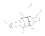
도 1은 본 발명의 일실시예에 따른 기관내 튜브의 외형을 개략적으로 나타낸 도면,
도 2는 도 1의 기관내 튜브에서 풍선형 팽창부 부분을 확대하여 나타낸 도면,
도 3은 도 2의 단면도
도 4는 도 3에서 X-X' 방향으로 절단한 경우 단면도, 그리고
도 5 및 도 6은 본 발명의 다른 실시예에 따른 기관내 튜브의 설명에 참조되는 도면이다.BRIEF DESCRIPTION OF THE DRAWINGS Fig. 1 is a schematic view of the outline of an endotracheal tube according to an embodiment of the present invention,
FIG. 2 is an enlarged view of a portion of the balloon-shaped expanding portion in the intracoracal tube of FIG. 1,
Figure 3 is a cross-
FIG. 4 is a sectional view taken along the line XX 'in FIG. 3, and FIG.
5 and 6 are views referred to the description of the endotracheal tube according to another embodiment of the present invention.
이하에서는 도면을 참조하여 본 발명을 보다 상세하게 설명한다.Hereinafter, the present invention will be described in detail with reference to the drawings.
도 1은 본 발명의 일실시예에 따른 기관내 튜브의 외형을 개략적으로 나타낸 도면이다.BRIEF DESCRIPTION OF THE DRAWINGS FIG. 1 is a schematic view showing the outline of an endotracheal tube according to an embodiment of the present invention; FIG.
도 1을 참조하면, 본 기관내 튜브(100)는 선단부(111)와 말단부(113)가 구비된 튜브형 본체(110)를 포함한다. 튜브형 본체(110)는 길고 속이 비어 있으며 굽어져 있어 가스의 유통이 가능하며, 튜브형 본체(110)의 선단부(111)는 환자의 기도 내부로 삽입되고, 말단부(113)에는 인공 호흡기 등에 부착될 수 있도록 커넥터(150)가 장착된다.Referring to FIG. 1,
튜브형 본체(110)에는 풍선형 팽창부(130)가 튜브형 본체(110)를 둘러싸도록 배치된다. 풍선형 팽창부(130)는 팽창튜브(120)와 연결되며, 팽창튜브(120)를 통해 주입되는 공기에 의해 팽창 가능하다. 따라서, 튜브형 본체(110)가 환자의 기도 내부로 삽입된 후, 팽창튜브(120)를 통해 주입되는 공기에 의해 풍선형 팽창부(130)가 팽창하면서 환자의 기관벽에 압력이 가해져 폐로부터 공기가 누출되는 것과 위액이 폐로 흡입되는 것을 방지할 수 있다.In the
팽창튜브(120)의 말단에 배치된 파일럿 벌룬(pilot balloon)(123)은 풍선형 팽창부(130) 팽창 체계의 이상 여부를 확인하고, 풍선형 팽창부(130) 안에 어느 정도의 공기가 채워져 있는지를 촉각적으로 알 수 있도록 한다.The
이와 같은 구성의 기관내 튜브(100)는 환자의 입이나 코를 통해 기관 내로 삽입된 후, 테이프나 고정장치 등을 이용하여 고정된다.The
도 2는 도 1의 기관내 튜브에서 풍선형 팽창부 부분을 확대하여 나타낸 도면이고, 도 3은 도 2의 단면도이며. 도 4는 도 3에서 X-X' 방향으로 절단한 경우의 풍선형 팽창부의 단면도이다.Fig. 2 is an enlarged view of a portion of the balloon-shaped expanding portion in the intracoracal tube of Fig. 1, and Fig. 3 is a sectional view of Fig. 2. Fig. Fig. 4 is a cross-sectional view of the balloon-shaped expanding portion taken along the line X-X 'in Fig. 3;
도 2 내지 도 4를 참조하면, 본 발명에 따른 기관내 튜브(100)는 풍선형 팽창부(130)에 인디케이터부(131, 133, 135, 137)가 설치되어 있다. 인디케이터부(131, 133, 135, 137)는 풍선형 팽창부(130)의 형태, 위치, 장착 상태 등을 파악하기 위해 사용된다.2 to 4, the
인디케이터부(131, 133, 135, 137)는 풍선형 팽창부(130)의 길이 방향으로 상하에 배치된 제1 인디케이터부(131)와 제2 인디케이터부(133), 그리고 풍선형 팽창부(130)의 외주면 방향을 따라 좌우로 배치된 제3 인디케이터부(135) 및 제4 인디케이터부(137)를 포함한다. 이와 같이 인디케이터부(131, 133, 135, 137)가 여러 개로 구성된 것은, 풍선형 팽창부(130)의 팽창이나 수축에 방해가 되지 않도록 하기 위함이다.The
제1 내지 제4 인디케이터부(131, 133, 135, 137)는 금속 재질이나 기타 외부 기기에서 인식 가능한 재질로 만들 수 있다.The first to
예컨대, 스테인리스 스틸(stainless steel), 코발트-크롬 합금(cobalt-chrome alloy), 티타늄(titanium), 티타늄 합금(titanium alloy) 또는 니켈-티타늄 형상 기억 합금(nickel-titanium shape memory alloys) 또는 그 밖에 인체에 무해한 금속재료로 제1 내지 제4 인디케이터부(131, 133, 135, 137)를 형성할 수 있다.For example, stainless steel, cobalt-chrome alloy, titanium, titanium alloy or nickel-titanium shape memory alloys, The first to
제1 내지 제4 인디케이터부(131, 133, 135, 137)는 색상이 있는 PVC(Polyvinyl chloride)나 색상이 있는 실리콘 등의 재질로 만들 수도 있다. 또한, 제1 내지 제4 인디케이터부(131, 133, 135, 137) 중 일부는 금속 재질로 형성하고, 일부는 색상이 있는 PVC나 색상이 있는 실리콘으로 만들 수도 있다.The first to
그리고, 제1 내지 제4 인디케이터부(131, 133, 135, 137)에는 환자의 상태 파악이나 그 밖의 치료 목적 등의 용도로 사용할 수 있는 칩 또는 센서가 포함될 수도 있다.In addition, the first to
환자의 신체 밖에 배치된 X선, 초음파, 컴퓨터 단층 촬영이나 기타 인체를 투과할 수 있는 기기 등을 통해 제1 내지 제4 인디케이터부(131, 133, 135, 137)를 촬영하거나 형태를 파악하여, 풍선형 팽창부(130)가 팽창된 정도, 풍선형 팽창부(130)의 장착 상태, 풍선형 팽창부(130)의 위치 등을 파악할 수 있다.The first to
기관내 튜브(100)의 깊이가 너무 얕을 경우 발관되기 쉽고, 너무 깊어 기관지 삽관이 되는 경우, 동측의 긴장성 기흉, 반대편의 무기폐, 저산소증을 동반하는 등 여러 가지 합병증이 오기 쉽다. 따라서, 기관내 튜브(100)의 삽관 위치가 중요한 문제로 인식되고 있으며, 일반적으로 기관내 튜브(100)의 끝이 기관의 중간에 위치하는 것이 가장 이상적이라고 알려져 있다.If the depth of the
제1 내지 제4 인티케이터부(131, 133, 135, 137)의 위치를 파악함으로써, 풍선형 팽창부(130)의 위치를 파악하여, 이상적인 위치까지 기관내 위치(100)를 삽입할 수 있으며, 이상적인 위치로 이동시킬 수 있다.By grasping the positions of the first to
또한, 제1 내지 제4 인티케이터부(131, 133, 135, 137)의 형태를 파악함으로써, 풍선형 팽창부(130)의 팽창 형태나 장착 상태를 파악하여 환자에게 무리가 없는 상태로 풍선형 팽창부(130)의 공기압을 조절할 수 있다. 과도하게 높거나 낮은 압력으로 팽창된 풍선형 팽창부(130)는 합병증을 유발할 수 있으므로 적정 압력을 유지해야 하는데, 본 기관내 튜브(100)는 풍선형 팽창부(130)가 적정 압력을 유지할 수 있도록 하여 환자가 느끼는 고통을 최소화하고, 풍선형 팽창부(130)가 접촉되는 신체 부위 등에서 문제가 발생하는 것을 방지할 수 있다.By grasping the shapes of the first to
한편, 기관내 튜브(100)는 다양한 크기로 제작이 가능하다. 즉, 사람의 나이, 성별에 따라 목구멍의 크기가 모두 다르기 때문이다. 기관내 튜브(100)의 크기는 튜브형 본체(110)의 내경을 기준으로 다양한 굵기로 제작이 가능하다. 기관내 튜브(100)의 크기는 공식에 따라 정하기도 하고, 의사의 임상판단에 따라 정하기도 한다.Meanwhile, the
또한, 튜브형 본체(110)는 일반적으로 의료용 튜브에 사용되는 다양한 재질로 형성될 수 있다. 그리고, 풍선형 팽창부(130)는 일반적으로 의료용 튜브에 사용되는 다양한 연질의 재료로 형성할 수 있다. 즉, 엘라스토머, 실리콘 및 연질 수지로 이루어진 그룹에서 선택된 하나 이상의 것으로 풍선형 팽창부(130)를 형성할 수 있다.In addition, the
이와 같이 풍선형 팽창부(130)를 연질의 재료를 사용하여 형성함으로써, 기관내 튜브의 삽입에 따른 불편함이나 이물질감을 감소시킬 수 있으며, 기관내 삽관으로 인한 합병증 유발도 최소화할 수 있다.By forming the
기관에 삽관된 기관내 튜브(100)는, 환자 스스로 숨을 쉴 수 있거나, 스스로 가래를 배출할 수 있는 경우 등에 제거할 수 있다. 즉, 인공기도가 필요했던 기저 상황이 호전되었을 때, 인공기도를 계속 유지해야할 새로운 이유가 없으면서 혈역학적으로 안정될 때, 환자가 스스로 분비물을 제거할 수 있을 때, 기도 문제가 해결되어 흡인 가능성이 적을 때, 인공환기 지지가 더 이상 필요치 않을 때 등의 경우에 환자에 삽입되었던 기관내 튜브를 제거할 수 있다.
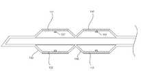
도 5 및 도 6은 본 발명의 다른 실시예에 따른 기관내 튜브에 대한 설명에 참조되는 도면이다.5 and 6 are views referred to the description of the endotracheal tube according to another embodiment of the present invention.
도 5를 참조하며, 풍선형 팽창부의 외주면을 따라 배치되는 인디케이터부(135, 137)는 한 쌍 이상이 배치될 수도 있다. 즉, 제1군의 인디케이터부(135a, 137a)외에 제2 군의 인디케이터부(137a, 137b)를 더 배치할 수 있으며, 이보다 더 많은 개수의 인디케이터부를 배치할 수도 있다. 마찬가지로, 풍선형 팽창부(130)의 길이 방향으로 배치되는 인디케이티부(131, 133)의 경우에도 추가로 더 배치할 수도 있다.Referring to FIG. 5, more than one pair of
도 6을 참조하면, 튜브형 본체(110)에 배치되는 제1 풍선형 팽창부(130)와 함께 추가로 제2 풍선형 팽창부(140)를 더 배치할 수도 있다. 이때, 제2 풍선형 팽창부(140)에도 제1 풍선형 팽창부(130)와 동일하게 인디케이터부(141, 143, 147)을 배치할 수 있다. .Referring to FIG. 6, the second balloon-shaped
이와 같은 구성에 의해, 기관내 튜브(100)의 삽관 위치 및 팽창 정도 등을 보다 정확하게 파악할 수 있다.With this configuration, it is possible to more accurately grasp the position of the
한편, 본 발명에 따른 기관삽입 튜브는 상기한 바와 같이 설명된 실시예들의 구성과 방법이 한정되게 적용될 수 있는 것이 아니라, 상기 실시예들은 다양한 변형이 이루어질 수 있도록 각 실시예들의 전부 또는 일부가 선택적으로 조합되어 구성될 수도 있다.It is to be noted that the present invention is not limited to the configuration and the method of the embodiments described above, but the embodiments may be modified so that all or some of the embodiments are selectively As shown in FIG.
또한, 이상에서는 본 발명의 바람직한 실시예에 대하여 도시하고 설명하였지만, 본 발명은 상술한 특정의 실시예에 한정되지 아니하며, 청구범위에서 청구하는 본 발명의 요지를 벗어남이 없이 당해 발명이 속하는 기술분야에서 통상의 지식을 가진자에 의해 다양한 변형실시가 가능한 것은 물론이고, 이러한 변형실시들은 본 발명의 기술적 사상이나 전망으로부터 개별적으로 이해되어서는 안될 것이다.While the present invention has been particularly shown and described with reference to exemplary embodiments thereof, it is to be understood that the invention is not limited to the disclosed exemplary embodiments, but, on the contrary, It should be understood that various modifications may be made by those skilled in the art without departing from the spirit and scope of the present invention.
110 : 튜브형 본체120 : 팽창튜브
123 : 파일럿밸룬130 : 풍선형 팽창부
131 : 제1 인디케이터부133 : 제2 인디케이터부
135 : 제3 인디케이터부137 : 제4 인디케이터부110: tubular body 120: expansion tube
123: pilot balloon 130: balloon-shaped expanding part
131: first indicator unit 133: second indicator unit
135: third indicator section 137: fourth indicator section
Claims (7)
Translated fromKorean엘라스토머, 실리콘 및 연질 수지로 이루어진 그룹에서 선택된 하나 이상의 것으로 형성되며, 상기 튜브형 본체의 일방을 둘러싸며 팽창 가능한 풍선형 팽창부;
상기 풍선형 팽창부를 팽창시키기 위한 공기가 주입되는 팽창 튜브;
상기 팽창 튜브의 말단에 배치되어, 상기 풍선형 팽창부의 팽창 체계의 이상 여부 및 팽창 정도를 파악할 수 있도록 하는 파일럿 벌룬;
상기 풍선형 팽창부의 길이 방향으로 상하에 각각 배치되는 제1 및 제2 인디케이터부,
상기 풍선형 팽창부의 외주면 방향을 따라 상기 풍선형 팽창부의 좌우에 각각 배치되는 제1 쌍의 인디케이터부, 및
상기 제1 쌍의 인디케이터부와 다른 위치에서, 상기 풍선형 팽창부의 외주면방향을 따라 상기 풍선형 팽창부의 좌우에 각각 배치되는 제2 쌍의 인디케이터부를 구비하며,
금속 재질, 색상이 있는 PVC(Polyvinyl chloride), 및 색상이 있는 실리콘인 중 적어도 하나의 재질로 형성하며, 상기 풍선형 팽창부에 배치되어, 상기 풍선형 팽창부의 형태, 위치, 및 장착 상태를 파악하기 위한 인디케이터부; 및
상기 풍선형 팽창부에 인접하게 배치되며, 상기 풍선형 팽창부와 동일한 형태로 상기 인디케이터부가 배치된 제2 풍선형 팽창부;를 포함하는 기관내 튜브.A tubular body inserted into an organ;
An expandable balloon-shaped expanding portion which is formed of at least one member selected from the group consisting of an elastomer, silicone and soft resin, and surrounds one side of the tubular body;
An inflation tube into which air is infused to inflate the inflated inflated portion;
A pilot balloon disposed at a distal end of the inflating tube to detect an abnormality of an inflating system of the inflated inflating unit and an inflation degree;
First and second indicator portions disposed on the upper and lower sides, respectively, in the longitudinal direction of the balloon-
A first pair of indicator portions disposed respectively on the left and right sides of the balloon expanding portion along the direction of the outer peripheral surface of the balloon expanding portion,
And a second pair of indicator portions disposed at left and right sides of the balloon-shaped bulged portion, respectively, in a direction different from the first pair of indicator portions and along the direction of the outer peripheral surface of the bulged-
Wherein the balloon-shaped inflated portion is formed of at least one material selected from the group consisting of a metal material, a polyvinyl chloride (PVC) having a color, and a silicone having a color, and is disposed in the inflated inflating portion to grasp the shape, An indicator unit And
And a second inflated bulged portion disposed adjacent to the inflated balloon-like inflated portion and having the indicator portion disposed in the same shape as the inflated balloon-shaped inflated portion.
엘라스토머, 실리콘 및 연질 수지로 이루어진 그룹에서 선택된 하나 이상의 것으로 형성되는 풍선형 팽창부를 상기 튜브형 본체의 일방을 둘러싸도록 배치하는 단계;
상기 풍선형 팽창부를 팽창시키기 위한 공기가 주입되는 팽창튜브를 설치하는 단계;
상기 풍선형 팽창부의 팽창 체계의 이상 여부 및 팽창 정도를 파악할 수 있도록 하는 파일럿 벌룬을 상기 팽창 튜브의 말단에 배치하는 단계;
상기 풍선형 팽창부에, 상기 풍선형 팽창부의 형태, 위치, 및 장착 상태를 파악하기 위한 인디케이터부를 배치하며,
상기 인디케이터부는, 금속 재질, 색상이 있는 PVC(Polyvinyl chloride), 및 색상이 있는 실리콘인 중 적어도 하나의 재질로 형성하고,
상기 인디케이터부는,
상기 풍선형 팽창부의 길이 방향으로 상하에 각각 배치되는 제1 및 제2 인디케이터부,
상기 풍선형 팽창부의 외주면 방향을 따라 상기 풍선형 팽창부의 좌우에 각각 배치되는 제1 쌍의 인디케이터부, 및
상기 제1 쌍의 인디케이터부와 다른 위치에서 상기 풍선형 팽창부의 외주면 방향을 따라 상기 풍선형 팽창부의 좌우에 각각 배치되는 제2 쌍의 인디케이터부를 구비하는 단계; 및
상기 풍선형 팽창부에 인접하게 배치되며, 상기 풍선형 팽창부와 동일한 형태로 상기 인디케이터부가 배치된 제2 풍선형 팽창부를 배치하는 단계를 포함하는 기관내 튜브의 제조방법.Providing a hollow tubular body;
Comprising the steps of: disposing a balloon-shaped bulge formed of at least one selected from the group consisting of an elastomer, silicone, and soft resin so as to surround one of the tubular bodies;
Providing an inflation tube into which air is infused to inflate the inflated inflated portion;
Disposing a pilot balloon at the distal end of the inflation tube so as to grasp the abnormality of the inflation system and the degree of inflation of the inflated inflation unit;
An indicator unit for grasping the shape, position, and mounting state of the balloon expander is disposed in the balloon expander,
The indicator unit may be formed of at least one material selected from the group consisting of a metal material, a polyvinyl chloride (PVC) having a color, and a silicone having a color,
Wherein the indicator unit comprises:
First and second indicator portions disposed on the upper and lower sides, respectively, in the longitudinal direction of the balloon-
A first pair of indicator portions disposed respectively on the left and right sides of the balloon expanding portion along the direction of the outer peripheral surface of the balloon expanding portion,
And a second pair of indicator portions disposed at left and right sides of the balloon-shaped expanding portion in a direction different from the first pair of indicator portions in the direction of the outer peripheral surface of the balloon-shaped expanding portion; And
And disposing a second inflated inflatable portion disposed adjacent to the inflatable inflatable portion and having the indicator portion in the same form as the inflatable inflatable portion.
Priority Applications (1)
| Application Number | Priority Date | Filing Date | Title |
|---|---|---|---|
| KR1020150066796AKR101807355B1 (en) | 2015-05-13 | 2015-05-13 | Endotracheal tube |
Applications Claiming Priority (1)
| Application Number | Priority Date | Filing Date | Title |
|---|---|---|---|
| KR1020150066796AKR101807355B1 (en) | 2015-05-13 | 2015-05-13 | Endotracheal tube |
Related Child Applications (1)
| Application Number | Title | Priority Date | Filing Date |
|---|---|---|---|
| KR1020170164837ADivisionKR20170138381A (en) | 2017-12-04 | 2017-12-04 | Endotracheal tube |
Publications (2)
| Publication Number | Publication Date |
|---|---|
| KR20160133803A KR20160133803A (en) | 2016-11-23 |
| KR101807355B1true KR101807355B1 (en) | 2017-12-11 |
Family
ID=57541279
Family Applications (1)
| Application Number | Title | Priority Date | Filing Date |
|---|---|---|---|
| KR1020150066796AActiveKR101807355B1 (en) | 2015-05-13 | 2015-05-13 | Endotracheal tube |
Country Status (1)
| Country | Link |
|---|---|
| KR (1) | KR101807355B1 (en) |
Families Citing this family (1)
| Publication number | Priority date | Publication date | Assignee | Title |
|---|---|---|---|---|
| CN115282418A (en)* | 2022-01-07 | 2022-11-04 | 郑州大学第一附属医院 | Cardiac surgery air flue nursing pipe |
Citations (5)
| Publication number | Priority date | Publication date | Assignee | Title |
|---|---|---|---|---|
| US5785051A (en) | 1996-06-21 | 1998-07-28 | University Of Rochester | Signal generating endotracheal tube apparatus |
| US20070137651A1 (en)* | 2005-12-16 | 2007-06-21 | Ezc Medical Llc | Visualization esophageal-tracheal airway apparatus and methods |
| US20090301643A1 (en)* | 2008-06-02 | 2009-12-10 | Loma Vista Medical, Inc. | Inflatable medical devices |
| CN202682502U (en) | 2012-05-10 | 2013-01-23 | 章沁丹 | Tracheal tube with cuff positioning function |
| WO2014158546A1 (en) | 2013-03-12 | 2014-10-02 | Acclarent, Inc. | Apparatus for sensing and responding to strain in airway dilation shaft |
- 2015
- 2015-05-13KRKR1020150066796Apatent/KR101807355B1/enactiveActive
Patent Citations (5)
| Publication number | Priority date | Publication date | Assignee | Title |
|---|---|---|---|---|
| US5785051A (en) | 1996-06-21 | 1998-07-28 | University Of Rochester | Signal generating endotracheal tube apparatus |
| US20070137651A1 (en)* | 2005-12-16 | 2007-06-21 | Ezc Medical Llc | Visualization esophageal-tracheal airway apparatus and methods |
| US20090301643A1 (en)* | 2008-06-02 | 2009-12-10 | Loma Vista Medical, Inc. | Inflatable medical devices |
| CN202682502U (en) | 2012-05-10 | 2013-01-23 | 章沁丹 | Tracheal tube with cuff positioning function |
| WO2014158546A1 (en) | 2013-03-12 | 2014-10-02 | Acclarent, Inc. | Apparatus for sensing and responding to strain in airway dilation shaft |
Also Published As
| Publication number | Publication date |
|---|---|
| KR20160133803A (en) | 2016-11-23 |
Similar Documents
| Publication | Publication Date | Title |
|---|---|---|
| US6792943B2 (en) | Intubating ventilatory face mask | |
| US5791341A (en) | Oropharyngeal stent with laryngeal aditus shield and nasal airway with laryngeal aditus shield | |
| EP0596517A1 (en) | Emergency resuscitation apparatus | |
| JPH07213614A (en) | Air passageway for gullet and trachea | |
| AU2014343497B2 (en) | Airway tube | |
| CN217612362U (en) | Multifunctional trachea cannula catheter | |
| CN109939320B (en) | Nasopharynx ventilation pipeline | |
| CN205515880U (en) | A multifunctional breathing airway management device | |
| JPH10179745A (en) | Intra-esophagus airway for emergency resuscitation | |
| Dunn et al. | Endotracheal tubes and airway appliances | |
| CN111867442B (en) | Supraglottic airway device with dynamic cuff having ventilation capability | |
| KR20160133139A (en) | Endotracheal tube | |
| KR101807355B1 (en) | Endotracheal tube | |
| EP2915554B1 (en) | Intubation device | |
| JP2015073678A (en) | Tracheal intubation tube | |
| GB2567870B (en) | Nasal endotracheal tube assembly | |
| KR20170027754A (en) | Endotracheal tube | |
| JP3734763B2 (en) | Resuscitation tube | |
| CN113289188B (en) | Multifunctional trachea cannula catheter | |
| CN110732069A (en) | Trachea cannula capable of conducting esophagus drainage | |
| EP4387695A1 (en) | Endotracheal tube and methods of use | |
| KR20170138381A (en) | Endotracheal tube | |
| CN219963673U (en) | A double-balloon endotracheal intubation catheter | |
| KR20150005827A (en) | An Endoscopic Laryngeal Mask Airway | |
| Tripathy et al. | Supraglottic Airway Devices |
Legal Events
| Date | Code | Title | Description |
|---|---|---|---|
| A201 | Request for examination | ||
| PA0109 | Patent application | Patent event code:PA01091R01D Comment text:Patent Application Patent event date:20150513 | |
| PA0201 | Request for examination | ||
| E902 | Notification of reason for refusal | ||
| PE0902 | Notice of grounds for rejection | Comment text:Notification of reason for refusal Patent event date:20160614 Patent event code:PE09021S01D | |
| PG1501 | Laying open of application | ||
| E90F | Notification of reason for final refusal | ||
| PE0902 | Notice of grounds for rejection | Comment text:Final Notice of Reason for Refusal Patent event date:20170124 Patent event code:PE09021S02D | |
| E90F | Notification of reason for final refusal | ||
| PE0902 | Notice of grounds for rejection | Comment text:Final Notice of Reason for Refusal Patent event date:20170725 Patent event code:PE09021S02D | |
| PE0701 | Decision of registration | Patent event code:PE07011S01D Comment text:Decision to Grant Registration Patent event date:20171130 | |
| A107 | Divisional application of patent | ||
| GRNT | Written decision to grant | ||
| PA0107 | Divisional application | Comment text:Divisional Application of Patent Patent event date:20171204 Patent event code:PA01071R01D | |
| PR0701 | Registration of establishment | Comment text:Registration of Establishment Patent event date:20171204 Patent event code:PR07011E01D | |
| PR1002 | Payment of registration fee | Payment date:20171204 End annual number:3 Start annual number:1 | |
| PG1601 | Publication of registration | ||
| PR1001 | Payment of annual fee | Payment date:20201102 Start annual number:4 End annual number:4 | |
| PR1001 | Payment of annual fee | Payment date:20220112 Start annual number:5 End annual number:5 | |
| PR1001 | Payment of annual fee | Payment date:20221212 Start annual number:6 End annual number:6 | |
| PR1001 | Payment of annual fee | Payment date:20231204 Start annual number:7 End annual number:7 | |
| PR1001 | Payment of annual fee | Payment date:20241001 Start annual number:8 End annual number:8 |