KR101806317B1 - Spinning tube for two-component composited nanofiber and method of manufacturing two-component composited nanofiber thereby - Google Patents
Spinning tube for two-component composited nanofiber and method of manufacturing two-component composited nanofiber therebyDownload PDFInfo
- Publication number
- KR101806317B1 KR101806317B1KR1020150150609AKR20150150609AKR101806317B1KR 101806317 B1KR101806317 B1KR 101806317B1KR 1020150150609 AKR1020150150609 AKR 1020150150609AKR 20150150609 AKR20150150609 AKR 20150150609AKR 101806317 B1KR101806317 B1KR 101806317B1
- Authority
- KR
- South Korea
- Prior art keywords
- tube
- spinning solution
- nanofiber
- composite nanofiber
- hollow portion
- Prior art date
- Legal status (The legal status is an assumption and is not a legal conclusion. Google has not performed a legal analysis and makes no representation as to the accuracy of the status listed.)
- Active
Links
- 239000002121nanofiberSubstances0.000titleabstractdescription68
- 238000009987spinningMethods0.000titleabstractdescription62
- 238000004519manufacturing processMethods0.000titleabstractdescription22
- 239000002131composite materialSubstances0.000claimsabstractdescription60
- 230000005855radiationEffects0.000claimsabstractdescription38
- 230000002093peripheral effectEffects0.000claimsabstractdescription5
- 239000000835fiberSubstances0.000claimsdescription6
- 239000002071nanotubeSubstances0.000claims1
- 238000000034methodMethods0.000abstractdescription7
- 239000002904solventSubstances0.000abstractdescription4
- 238000011084recoveryMethods0.000abstractdescription2
- 239000000306componentSubstances0.000description36
- 229920002239polyacrylonitrilePolymers0.000description12
- ZMXDDKWLCZADIW-UHFFFAOYSA-NN,N-DimethylformamideChemical compoundCN(C)C=OZMXDDKWLCZADIW-UHFFFAOYSA-N0.000description6
- 229920003229poly(methyl methacrylate)Polymers0.000description6
- 229920000642polymerPolymers0.000description6
- 239000004926polymethyl methacrylateSubstances0.000description6
- 239000004372Polyvinyl alcoholSubstances0.000description5
- 238000007796conventional methodMethods0.000description5
- 238000001523electrospinningMethods0.000description5
- 239000007788liquidSubstances0.000description5
- 229920002451polyvinyl alcoholPolymers0.000description5
- 239000002134carbon nanofiberSubstances0.000description4
- 239000000463materialSubstances0.000description4
- VNWKTOKETHGBQD-UHFFFAOYSA-NmethaneChemical classCVNWKTOKETHGBQD-UHFFFAOYSA-N0.000description4
- 239000008358core componentSubstances0.000description3
- 238000009826distributionMethods0.000description3
- 239000002243precursorSubstances0.000description3
- 229910006404SnO 2Inorganic materials0.000description2
- 229910010413TiO 2Inorganic materials0.000description2
- 239000012510hollow fiberSubstances0.000description2
- 229910010272inorganic materialInorganic materials0.000description2
- 239000011147inorganic materialSubstances0.000description2
- 239000003960organic solventSubstances0.000description2
- BASFCYQUMIYNBI-UHFFFAOYSA-NplatinumChemical compound[Pt]BASFCYQUMIYNBI-UHFFFAOYSA-N0.000description2
- 239000002133porous carbon nanofiberSubstances0.000description2
- 239000007787solidSubstances0.000description2
- XLYOFNOQVPJJNP-UHFFFAOYSA-NwaterSubstancesOXLYOFNOQVPJJNP-UHFFFAOYSA-N0.000description2
- 238000003917TEM imageMethods0.000description1
- 239000004809TeflonSubstances0.000description1
- 229920006362Teflon®Polymers0.000description1
- 230000005540biological transmissionEffects0.000description1
- 238000003763carbonizationMethods0.000description1
- 238000004140cleaningMethods0.000description1
- 238000012377drug deliveryMethods0.000description1
- 239000007772electrode materialSubstances0.000description1
- 239000012530fluidSubstances0.000description1
- 229910052500inorganic mineralInorganic materials0.000description1
- 239000012528membraneSubstances0.000description1
- 239000011707mineralSubstances0.000description1
- 229910052697platinumInorganic materials0.000description1
- 239000007921spraySubstances0.000description1
Images


Classifications
- D—TEXTILES; PAPER
- D01—NATURAL OR MAN-MADE THREADS OR FIBRES; SPINNING
- D01D—MECHANICAL METHODS OR APPARATUS IN THE MANUFACTURE OF ARTIFICIAL FILAMENTS, THREADS, FIBRES, BRISTLES OR RIBBONS
- D01D5/00—Formation of filaments, threads, or the like
- D01D5/0007—Electro-spinning
- D01D5/0061—Electro-spinning characterised by the electro-spinning apparatus
- D01D5/0069—Electro-spinning characterised by the electro-spinning apparatus characterised by the spinning section, e.g. capillary tube, protrusion or pin
- D—TEXTILES; PAPER
- D01—NATURAL OR MAN-MADE THREADS OR FIBRES; SPINNING
- D01D—MECHANICAL METHODS OR APPARATUS IN THE MANUFACTURE OF ARTIFICIAL FILAMENTS, THREADS, FIBRES, BRISTLES OR RIBBONS
- D01D5/00—Formation of filaments, threads, or the like
- D01D5/0007—Electro-spinning
- D01D5/0061—Electro-spinning characterised by the electro-spinning apparatus
- D—TEXTILES; PAPER
- D01—NATURAL OR MAN-MADE THREADS OR FIBRES; SPINNING
- D01D—MECHANICAL METHODS OR APPARATUS IN THE MANUFACTURE OF ARTIFICIAL FILAMENTS, THREADS, FIBRES, BRISTLES OR RIBBONS
- D01D5/00—Formation of filaments, threads, or the like
- D01D5/28—Formation of filaments, threads, or the like while mixing different spinning solutions or melts during the spinning operation; Spinnerette packs therefor
- D01D5/30—Conjugate filaments; Spinnerette packs therefor
- D01D5/34—Core-skin structure; Spinnerette packs therefor
- D—TEXTILES; PAPER
- D04—BRAIDING; LACE-MAKING; KNITTING; TRIMMINGS; NON-WOVEN FABRICS
- D04H—MAKING TEXTILE FABRICS, e.g. FROM FIBRES OR FILAMENTARY MATERIAL; FABRICS MADE BY SUCH PROCESSES OR APPARATUS, e.g. FELTS, NON-WOVEN FABRICS; COTTON-WOOL; WADDING ; NON-WOVEN FABRICS FROM STAPLE FIBRES, FILAMENTS OR YARNS, BONDED WITH AT LEAST ONE WEB-LIKE MATERIAL DURING THEIR CONSOLIDATION
- D04H1/00—Non-woven fabrics formed wholly or mainly of staple fibres or like relatively short fibres
- D04H1/70—Non-woven fabrics formed wholly or mainly of staple fibres or like relatively short fibres characterised by the method of forming fleeces or layers, e.g. reorientation of fibres
- D04H1/72—Non-woven fabrics formed wholly or mainly of staple fibres or like relatively short fibres characterised by the method of forming fleeces or layers, e.g. reorientation of fibres the fibres being randomly arranged
- D04H1/728—Non-woven fabrics formed wholly or mainly of staple fibres or like relatively short fibres characterised by the method of forming fleeces or layers, e.g. reorientation of fibres the fibres being randomly arranged by electro-spinning
Landscapes
- Engineering & Computer Science (AREA)
- Textile Engineering (AREA)
- Mechanical Engineering (AREA)
- Spinning Methods And Devices For Manufacturing Artificial Fibers (AREA)
Abstract
Translated fromKoreanDescription
Translated fromKorean본 발명은 2성분 복합 나노섬유 제조용 방사튜브(이하 "방사튜브" 라고 약칭한다) 및 이를 이용한 2성분 복합 나노섬유의 제조방법에 관한 것으로서, 보다 구체적으로는 높은 단위시간당 생산성과 공정성으로 고품질의 2성분 복합 나노섬유 웹을 제조할 수 있는 방사튜브에 관한 것이며, 또한, 상기 방사튜브를 이용하여 고품질의 2성분 복합 나노섬유 웹을 제조하는 방법에 관한 것이다.TECHNICAL FIELD The present invention relates to a radial tube for manufacturing a two-component composite nanofiber (hereinafter abbreviated as "radial tube") and a method for manufacturing a two-component composite nanofiber using the same, more specifically, The present invention relates to a radiation tube capable of producing a composite nano-fiber web, and also to a method for producing a high-quality two-component composite nano-fiber web using the radiation tube.
본 발명의 상기 "2성분 복합 나노섬유"라는 용어는 코어-시스형 복합 나노섬유와 사이드-바이-사이드형 복합 나노섬유 모두를 포함하는 의미로 사용되며, 상기 "코어-시스형 복합 나노섬유"라는 용어는 편심형 코어-시스형 복합 나노섬유도 포함하는 의미로 사용된다.The term " two-component composite nanofiber "of the present invention is used to include both core-sheath type composite nanofiber and side-by-side type composite nanofiber, Is used to mean also an eccentric core-sheath type composite nanofiber.
시스-코어형 복합 나노섬유를 제조하는 종래기술로서는 시스/코어 형태(2중관 형태)의 노즐을 통해 시스 형성용 방사용액과 코어 형성용 방사용액을 정전기력만으로 전기방사 하는 방법이 널리 사용되어 왔다.As a conventional technique for producing cis-core type composite nanofibers, a method of electrospinning a spray solution for forming a sheath and a spinning solution for forming a core through a nozzle of a sheath / core type (double pipe type) with electrostatic force has been widely used.
그러나, 상기 종래방법은 정전기력에만 의존하여 전기방사를 하기 때문에 단위시간당 노즐 단위홀당 토출량이 0.01g 수준으로 매우 낮아 생산성이 떨어져 결국 양산화가 곤란하였고, 노즐 교체 및 청소도 매우 번거로운 문제점이 있었다.However, since the above-mentioned conventional method relies solely on the electrostatic force to perform electrospinning, the discharge amount per nozzle unit per unit time per unit time is extremely low to 0.01 g, which leads to a problem of productivity and difficulty in mass production.
일반적으로 전기방사를 통한 나노섬유의 생산량은 시간당 0.1~1 g 수준이고 용액 토출량은 시간당 1.0~5.0 mL 수준으로 매우 낮다[D. H. H. Renecker 등, Nanptechnology 2006, VOl 17, 1123]In general, the production of nanofibers through electrospinning is 0.1 to 1 g per hour, and the solution discharge rate is very low, ranging from 1.0 to 5.0 mL per hour [D. H. H. Renecker et al., Nanptechnology 2006, Vo 17, 1123]
구체적으로, 나노레터(Nano Letter), 2007, Vol7(4) 1081에는 또 다른 종래기술로서 2개의 노즐이 사이드 바이 사이드 형태로 배열된 복합노즐 중 내부직경이 0.4㎜인 하나의 노즐에 SnO2인 프리커서 용액을 공급하고, 내부 직경이 0.7㎜인 나머지 노즐에 TiO2프리커서 용액을 공급한 후 전기방사하여 사이드-바이-사이드 형태인 TiO2/SnO2 복합 무기나노섬유를 제조하는 방법을 게재하고 있으나, 상기 종래방법은 정전기력만 의존하기 때문에 단위시간당 노즐 1개당 토출량이 매우 낮아 생산성이 떨어지고, 노즐교체 및 청소가 어려운 문제점이 있었다.Specifically, the nano-letter (Nano Letter), 2007, Vol7 (4) 1081 is another prior art as a side-by-two nozzles, one of SnO2 in a nozzle inside diameter of the composite nozzle arranged in a side-form is 0.4㎜ The precursor solution was supplied, and the other nozzle having an inner diameter of 0.7 mm was charged with TiO2 A method of producing TiO2 / SnO2 composite inorganic nanofibers in a side-by-side configuration is provided. However, since the conventional method depends on only the electrostatic force, the discharge amount per nozzle per unit time The productivity is deteriorated, and nozzle replacement and cleaning are difficult.
폴리머(Polymer), 2003, Vol.44, 6353에서는 내부 직경이 0.7mm 이고 두께가 0.2mmm인 테프론 니들을 사용하고 여기에 두 종류의 용액이 니들 부분에서 합쳐지도록 실린더 펌프로 동시에 두 종류의 용액을 공급하고 백금 전극을 용액 내에 설치하여 전기방사를 행하여 사이드 바이 사이드 형태의 복합 나노섬유를 제조하는 방법을 게재하고 있으나, 상기 종래방법 역시 정전기력에만 의존하기 때문에 단위시간당 노즐 1개당 토출량이 매우 낮아 생산성이 떨어지고, 노즐 교체 및 청소가 어려운 문제점이 있었다.In Polymer, 2003, Vol. 44, 6353, a Teflon needle having an inner diameter of 0.7 mm and a thickness of 0.2 mmm was used, and two kinds of solutions were simultaneously injected into a cylinder pump so that two kinds of solutions were combined at the needle part And a platinum electrode is placed in a solution to perform electrospinning to produce a side-by-side composite nanofiber. However, since the conventional method also depends only on the electrostatic force, the discharge amount per nozzle per unit time is very low, There is a problem that it is difficult to remove and replace the nozzle and clean it.
또한, 상기 종래방법들은 방사용액이 섬유상이 아닌 용액상태로 컬렉터 상에 떨어지는 현상(이하 "드롭렛 현상"이라고 한다)이 심하게 발생되어 2성분 복합 나노섬유 웹의 품질이 저하되는 문제도 있었다.In addition, the above conventional methods have a problem that the phenomenon in which the spinning solution falls on the collector in a solution state not in the form of a fiber (hereinafter referred to as "droplet phenomenon") is severely generated, and the quality of the two-component composite nanofiber web deteriorates.
본 발명은 과제는 고전압 인가로 인한 작업 위험성을 최소화할 수 있고, 2성분 복합 나노섬유의 생산성을 크게 향상시킬 수 있고, 나노섬유 제조시 드롭렛 현상을 방지하여 2성분 복합 나노섬유 웹의 품질을 향상시킬 수 있는 2성분 복합 나노섬유 제조용 방사튜브를 제공하는 것이다.The object of the present invention is to minimize the risk of work due to the application of high voltage and to greatly improve the productivity of the two-component composite nanofiber and to prevent the droplet phenomenon in the production of the nanofiber, And to provide a radiant tube for manufacturing a bicomponent composite nanofiber that can be improved.
본 발명의 또 다른 과제는 상기 2성분 복합 나노섬유 제조용 방사튜브를 사용해서 높은 생산성으로 고품질의 2성분 복합 나노섬유를 제조하는 방법을 제공하는 것이다.Another object of the present invention is to provide a method for producing high-quality two-component composite nanofibers with high productivity by using a radial tube for producing the two-component composite nanofibers.
이와 같은 과제를 달성하기 위해서 본 발명에서는 2성분 복합 나노섬유 제조용 방사튜브(1)를 (ⅰ) 원통형 및 원추형 중에서 선택된 하나의 형태를 구비하는 방사튜브 본체(1a), (ⅱ) 상기 방사튜브 본체(1a)의 내부에 상기 방사튜브 본체(1a)의 길이방향을 따라 형성되어 있는 다각형 튜브상 중공부(1b) 및 (ⅲ) 상기 다각형 튜브상 중공부(1b)의 모서리 부분 각각에 상기 방사튜브 본체(1a)의 길이방향을 따라 설치되어 있는 노즐(1c)로 구성한다.In order to achieve the above object, the present invention provides a radiant tube 1 for manufacturing a bicomponent composite nanofiber, comprising: (i) a radiation tube
이때, 상기 다각형 튜브상 중공부(1b)의 모서리 부분들이 방사튜브 본체(1a)의 외주면과 맞닿도록 형성시켜 준다.At this time, the corner portions of the
또한, 본 발명은 (ⅰ) 상기 2성분 복합 나노섬유 제조용 방사튜브(1)를 모터(7)로 회전시켜 주면서 전압발생장치(6)로 상기 2성분 복합 나노섬유 제조용 방사튜브(1)에 고전압을 걸어준 다음, (ⅱ) 상기 2성분 복합 나노섬유 제조용 방사튜브(1)를 이루는 노즐(1c) 내로 제1방사용액을 공급함과 동시에 상기 2성분 복합 나노섬유 제조용 방사튜브(1)를 이루는 다각형 튜브상 중공부(1b) 내로 상기 제1방사용액과 상이한 제2방사용액을 공급한 다음, (ⅲ) 노즐(1c) 내로 공급된 제1방사용액과 다각형 튜브상 중공부(1b) 내로 공급된 제2방사용액을 원심력과 전기력을 이용하여 전압발생장치(6)에 의해 고전압이 걸려 있는 컬렉터(2) 방향으로 방사하여 2성분 복합 나노섬유를 제조한다.The present invention also relates to a method for producing a two-component composite nanofiber, comprising the steps of: (i) rotating the spinning tube 1 for manufacturing the two-component complex nanofiber with a motor 7, (Ii) supplying the first spinning solution into the
본 발명은 정전기력과 원심력을 동시에 이용하기 때문에 2성분 복합 나노섬유를 높은 생산성(토출량)으로 제조할 수 있고, 용매 휘발 및 회수가 용이하고, 방사액이 섬유상이 아닌 용액상태로 컬렉터 상에 떨어지는 현상(드롭 현상)도 효과적으로 방지하여 2성분 복합 나노섬유 웹의 품질을 향상시키는 효과가 있다.The present invention relates to a process for producing a two-component composite nanofiber with high productivity (discharge amount) because it uses electrostatic force and centrifugal force at the same time, facilitates solvent volatilization and recovery, (Drop phenomenon) is effectively prevented, thereby improving the quality of the two-component composite nanofiber web.
도 1은 본 발명에 따른 2성분 복합 나노섬유를 제조하는 공정 개략도.
도 2는 본 발명의 2성분 복합 나노섬유 제조용 방사튜브(1)의 사시개략도.
도 3 내지 도 4는 본 발명의 방사튜브(1)에 형성된 다각형 튜브상 중공(1b)의 모서리 부분에 노즐(1c)이 형성된 상태를 나타내는 모식도.
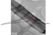
도 5는 실시예 1로 제조한 2성분 복합 나노섬유의 투과전자현미경 사진.1 is a schematic view of a process for producing a two-component composite nanofiber according to the present invention.
2 is a perspective view schematically showing a spinning tube 1 for producing a two-component composite nanofiber according to the present invention.
3 to 4 are schematic views showing a state in which a
Fig. 5 is a transmission electron micrograph of the two-component composite nanofiber prepared in Example 1. Fig.
이하, 첨부한 도면 등을 통하여 본 발명을 상세하게 설명한다.Hereinafter, the present invention will be described in detail with reference to the accompanying drawings.
본 발명에 따른 2성분 복합 나노섬유 제조용 방사튜브는 도 1 및 도 2에 도시된 바와 같이 (ⅰ) 원통형 및 원추형 중에서 선택된 하나의 형태를 구비하는 방사튜브 본체(1a), (ⅱ) 상기 방사튜브 본체(1a)의 내부에 상기 방사튜브 본체(1a)의 길이방향을 따라 형성되어 있는 다각형 튜브상 중공부(1b) 및 (ⅲ) 상기 다각형 튜브상 중공부(1b)의 모서리 부분 각각에 상기 방사튜브 본체(1a)의 길이방향을 따라 설치되어 있는 노즐(1c)로 구성되며, 상기 다각형 튜브상 중공부(1b)의 모서리 부분들이 방사튜브 본체(1a)의 외주면과 맞닿아 있는 구조를 구비한다.As shown in FIGS. 1 and 2, the radiation tube for manufacturing a bicomponent composite nanofiber according to the present invention comprises (i) a radiation tube
상기 다각형 튜브상 중공부(1b)의 모서리 부분 각각에는 1개 또는 2개 이상의 노즐(1c)이 방사튜브의 본체(1a) 길이방향을 따라 설치되어 있다.One or two or
다음으로는, 본 발명에 따른 2성분 복합 나노섬유의 제조방법을 살펴보면, 도 1에 도시된 바와 같이 (ⅰ) 상기 2성분 복합 나노섬유 제조용 방사튜브(1)를 모터(7)로 회전시켜 주면서 전압발생장치(6)로 상기 2성분 복합 나노섬유 제조용 방사튜브(1)에 고전압을 걸어준 다음, (ⅱ) 상기 2성분 복합 나노섬유 제조용 방사튜브(1)를 이루는 노즐(1c) 내로 제1방사용액을 공급함과 동시에 상기 2성분 복합 나노섬유 제조용 방사튜브(1)를 이루는 다각형 튜브상 중공부(1b) 내로 상기 제1방사용액과 상이한 제2방사용액을 공급한 다음, (ⅲ) 노즐(1c) 내로 공급된 제1방사용액과 다각형 튜브상 중공부(1b) 내로 공급된 제2방사용액을 원심력과 전기력을 이용하여 전압발생장치(6)에 의해 고전압이 걸려 있는 컬렉터(2) 방향으로 방사하여 2성분 복합 나노섬유를 제조한다.Next, as shown in FIG. 1, (i) the spinning tube 1 for manufacturing the two-component complex nanofiber is rotated by a motor 7, Component nano-fiber is produced by applying a high voltage to the radiation tube 1 for producing the two-component composite nanofiber by the voltage generating device 6 and then (i) injecting a first voltage into the
이때, 제1방사용액 분배판(3a)을 사용하여 노즐(1c) 내로 제1방사용액을 공급하고, 제2방사용액 분배판(3b)를 사용하여 다각형 튜브상 중공부(1b) 내로 제2방사용액을 공급한다.At this time, the first spinning solution is supplied into the
상기 2성분 복합 나노섬유는 코어-시스형(Core-sheath type) 복합 나노섬유 또는 사이드 바이 사이드형(Side by side type) 복합 나노섬유이며, 상기 코어-시스형 복합섬유는 편심형 코어-시스형 복합 나노섬유일 수도 있다.Wherein the two-component composite nanofiber is a core-sheath type composite nanofiber or a side by side type composite nanofiber, and the core-sheath type composite fiber is an eccentric core- It may be a composite nanofiber.
구현일례로서, 노즐(1c) 내로는 코어형성용 방사용액(제1방사용액)을 공급하고, 다각형 튜브상 중공부(1b) 내로는 시스형성용 방사용액(제2방사용액)을 공급하여 코어-시스형 복합 나노섬유를 제조한다.As an example of implementation, a spinning liquid for forming a core (a first spinning solution) is supplied into a
이때, 도 4에 도시된 바와 같이 다각형 튜브상 중공부(1b)의 모서리 부분 각각에 2개의 노즐(1c)들을 설치된 방사튜브(1)를 사용하면 코어성분이 2개인 코어-시스형 복합 나노섬유를 제조할 수 있다.4, when the radiation tube 1 provided with the two
또 다른 구현일례로서, 다각형 튜브상 중공부(1b)의 모서리 꼭지점과 노즐(1c)간의 거리(d)를 적절하게 조절하게 되면 사이드 바이 사이드형 복합 나노섬유를 제조할 수 있게 된다.As another embodiment, it is possible to manufacture the side-by-side composite nanofibers by appropriately adjusting the distance (d) between the corner vertex of the
구현일례로서, 서로 다른 고분자 용액 2종 중 1종을 노즐(1c) 내로 공급되는 제1방사용액으로 사용하고, 나머지 1종을 다각형 튜브상 중공부(1b) 내로 공급되는 제2방사용액으로 사용하여 코어-시스형 복합 나노섬유 또는 사이드 바이 사이드형 복합 나노섬유를 제조한다.As one example of implementation, one of the two different polymer solutions is used as the first spinning solution supplied into the
상기와 같이 제조된 코어-시스형 복합 나노섬유의 코어부를 유기용매 등으로 용해하며 중공섬유가 제조된다.The core part of the core-sheath type composite nanofiber prepared as described above is dissolved in an organic solvent or the like to produce a hollow fiber.
또 다른 구현일례로서, 서로 다른 무기물이 포함된 프리커서 2종 중 1종을 노즐(1c) 내로 공급되는 제1방사용액으로 사용하고, 나머지 1종을 다각형 튜브상 중공부(1b) 내로 공급되는 제2방용액으로 사용하여 2성분 복합 무기 나노섬유를 제조한다.In another embodiment, one of the two types of precursors containing different minerals is used as the first spinning solution supplied into the
이와 같이 제조된 2성분 복합 무기 나노섬유를 안정화 및 탄화처리하면 단일성분 또는 2성분 무기 나노섬유가 제조된다.The thus prepared two-component composite inorganic nanofiber is stabilized and carbonized to produce a single-component or two-component inorganic nanofiber.
또 다른 구현일례로서, 고분자 용액을 노즐(1c) 내로 공급되는 제1방사용액으로 사용하고, 무기물이 포함된 프리커서를 다각형 튜브상 중공부(1b) 내로 공급되는 제2방사용액으로 사용하여 코어성분이 고분자이고 쉬스 성분이 무기물로 구성된 코어-시스형 복합 나노섬유를 제조한다.As another embodiment, the polymer solution is used as the first spinning solution supplied into the
상기와 같이 제조된 코어-시스형 복합 나노섬유의 코어 성분을 유기용매 등으로 용해시키거나 탄화처리로 제거하게 되면 무기 중공섬유가 제조된다.When the core component of the core-sheath type composite nanofiber thus prepared is dissolved in an organic solvent or the like, or is removed by carbonization, an inorganic hollow fiber is produced.
본 발명의 방사튜브(1)를 이용하여 중공 탄소 나노섬유를 제조하는 구현일례를 살펴보면, 수용성 폴리비닐알코올 용액을 노즐(1c) 내로 공급되는 제1방사용액으로 사용하고, 폴리아크릴로니트릴 용액을 다각형 튜브상 중공부(1b) 내로 공급되는 제2방사용액으로 사용하여 코어-시스형 복합나노섬유를 제조한 다음, 코어부를 형성하는 수용성 폴리비닐알코올을 물로 제거하여 중공 폴리아크릴로니트릴 섬유를 제조한 다음, 제조된 중공 폴리아크릴로니트릴 섬유를 안정화 및 탄화처리하여 중공 탄소 나노섬유를 제조한다.An example of the production of hollow carbon nanofibers using the radiation tube 1 of the present invention is as follows. A water-soluble polyvinyl alcohol solution is used as a first spinning solution supplied into the
이때, 다각형 튜브상 중공부(1b)의 모서리 부분 각각에 2개 이상의 노즐(1c)들이 설치된 방사튜브를 사용하게 되면 다공성 탄소 나노섬유가 제조된다.At this time, when a radial tube having two or
상기와 같이 제조된 중공 탄소 나노섬유 또는 다공성 탄소 나노섬유는 필터소재, 2차전지 멤브레인 소재, 전극재료, 고기능성 의류 소재, 약물전달 소재 등으로 유용하다.The hollow carbon nanofibers or the porous carbon nanofibers prepared as described above are useful as a filter material, a secondary battery membrane material, an electrode material, a highly functional garment material, and a drug delivery material.
이하, 실시예를 통하여 본 발명을 보다 구체적으로 살펴본다.Hereinafter, the present invention will be described in more detail with reference to Examples.
그러나, 본 발명은 하기 실시예에 의해 보호범위가 한정되는 것은 아니다.However, the scope of protection of the present invention is not limited by the following examples.
실시예Example 1 One
폴리메틸메타아크릴레이트를 용매인 디메틸포름아미드에 용해하여 고형분이 10중량%인 폴리메틸메타아크릴레이트 용액(제1방사용액)을 제조하였다.Polymethylmethacrylate was dissolved in dimethylformamide as a solvent to prepare a polymethylmethacrylate solution (first spinning solution) having a solid content of 10% by weight.
폴리아크릴로니트릴을 용매인 디메틸포름아미드에 용해하여 고형분이 12중량%인 폴리아크릴로니트릴 용액(제2방사용액)을 제조하였다.Polyacrylonitrile was dissolved in dimethylformamide as a solvent to prepare a polyacrylonitrile solution (second spinning solution) having a solid content of 12% by weight.
다음으로, 도 1 및 도 2에 도시된 바와 같이 (ⅰ) 원통형 및 원추형 중에서 선택된 하나의 형태를 구비하는 방사튜브 본체(1a), (ⅱ) 상기 방사튜브 본체(1a)의 내부에 상기 방사튜브 본체(1a)의 길이방향을 따라 형성되어 있는 12 다각형 튜브상 중공부(1b) 및 (ⅲ) 상기 12 다각형 튜브상 중공부(1b)의 모서리 부분 각각에 상기 방사튜브 본체(1a)의 길이방향을 따라 설치되어 있는 직경이 0.7㎜인 노즐(1c)가 12개로 구성되며, 상기 다각형 튜브상 중공부(1b)의 모서리 부분들이 방사튜브 본체(1a)의 외주면과 맞닿아 있는 구조를 구비하는 방사튜브(1)를 모터(7)로 350rpm으로 회전시켜주면서 전압발생장치(6)로 상기 방사튜브(1)에 35kV의 전압을 걸어준 다음, 상기 방사튜브(1)를 이루는 노즐(1c)내로 폴리메틸메타아크릴레이트 용액(제1방사용액)을 공급함과 동시에 상기 방사튜브(1)를 이루는 다각형 튜브상 중공부(1b) 내로 폴리아크릴로니트릴 용액(제2방사용액)을 공급한 다음, 상기 공급된 상기 방사용액들을 35kV의 전압이 걸려 있는 컬렉터(2) 방향으로 전기방사하여 시스-코어형 2성분 복합 나노섬유를 제조하였다. 고분자 용액인 폴리아크릴로니트릴 용액(제2방사용액)은 분당 0.25cc로 공급하고 폴리메틸메타아크릴레이트 용액(제1방사용액)은 분당 0.20cc로 공급하였다. 이때 컬렉터(2)와 방사튜브(1) 간의 거리는 35㎝로 하였다.Next, as shown in Figs. 1 and 2, (i) a radiation tube
상기와 같이 제조된 시스-코어형 2성분 복합 나노섬유의 투과전자현미경 사진은 도 5와 같았다.The transmission electron microscope photograph of the cis-core type two-component composite nanofiber prepared as described above was as shown in FIG.
도 5에서는 직경이 300㎚ 정도인 코아성분의 폴리메틸메타아크릴레이트 성분 외부를 쉬스성분의 폴리아크릴로니트릴이 감싸고 있는 구조를 보여준다.Fig. 5 shows a structure in which a polyacrylonitrile of a sheath component surrounds the outside of a core-component polymethylmethacrylate component having a diameter of about 300 nm.
실시예Example 2 2
도 1 및 도 2에 도시된 바와 같이 (ⅰ) 원통형 및 원추형 중에서 선택된 하나의 형태를 구비하는 방사튜브 본체(1a), (ⅱ) 상기 방사튜브 본체(1a)의 내부에 상기 방사튜브 본체(1a)의 길이방향을 따라 형성되어 있는 12 다각형 튜브상 중공부(1b) 및 (ⅲ) 상기 12 다각형 튜브상 중공부(1b)의 모서리 부분 각각에 상기 방사튜브 본체(1a)의 길이방향을 따라 설치되어 있는 직경이 0.7㎜인 노즐(1c) 12개로 구성되며, 상기 다각형 튜브상 중공부(1b)의 모서리 부분들이 방사튜브 본체(1a)의 외주면과 맞닿아 있는 구조를 구비하는 방사튜브(1)를 모터(7)로 350rpm으로 회전시켜주면서 전압발생장치(6)로 상기 방사튜브(1)에 35kV의 전압을 걸어준 다음, 상기 방사튜브(1)를 이루는 노즐(1c)내로 수용 폴리비닐알코올 용액(제1방사용액)을 공급함과 동시에 상기 방사튜브(1)를 이루는 다각형 튜브상 중공부(1b) 내로 폴리아크릴로니트릴 용액(제2방사용액)을 공급한 다음, 상기 공급된 상기 방사용액들을 35kV의 전압이 걸려 있는 컬렉터(2) 방향으로 전기방사하여 시스-코어형 2성분 복합 나노섬유를 제조하였다. 고분자용액인 폴리아크릴로니트릴 용액(제2방사용액)은 분당 0.25cc로 공급하고 폴리비닐알코올 용액(제1방사용액)은 분당 0.18cc로 공급하였다. 이때 컬렉터(2)와 방사튜브 이때 컬렉터(2)와 방사튜브(1) 간의 거리는 35㎝로 하였다.(I) a radiation tube
상기와 같이 제조된 시스-코어형 2성분 복합 나노섬유를 물로 수세하여 코어부를 형성하는 수용성 폴리비닐알코올을 제거하여 중공 폴리아크릴로니트릴 섬유를 제조한 다음, 이를 안정화 및 탄화처리하여 중공 탄소 나노섬유를 제조하였다.The thus-prepared cis-core type two-component composite nano-fibers were washed with water to remove water-soluble polyvinyl alcohol forming the core portion to prepare hollow polyacrylonitrile fibers, and stabilized and carbonized to prepare hollow carbon nanofibers .
1 : 2성분 복합 나노섬유 제조용 방사튜브
1a : 방사튜브의 본체
1b : 다각형 튜브상 중공부 1c : 노즐
2: 컬렉터 3: 방사용액 분배판
3a : 제1방사용액(코어 형성용 방사용액) 분배판
3b : 제2방사용액(쉬스 형성용 방사용액) 분배판
4 : 제2방사용액(쉬스 형성용 방사용액) 공급탱크
5 : 제1방사용액(코어 형성용 방사용액) 공급탱크
6 : 전압발생장치 7 : 모터
F : 2성분 복합 나노섬유 Fc : 2성분 복합 나노섬유의 코어부
Fs : 2성분 복합 나노섬유의 쉬스부
X : 폴리아크릴 니트릴 Y : 폴리메틸메타아크릴레이트
d : 노즐(1c)과 상기 노즐과 가장 인접하는 다각형 튜브상 중공부(1b)의 모서리 꼭지점 간의 거리.1: Radiation tube for manufacturing 2-component composite nanofiber
1a: the body of the radiation tube
1b: hollow portion on the
2: Collector 3: Fluid distribution plate
3a: 1st spinning solution (spinning liquid for forming a core) distribution plate
3b: Second spinning solution (spinning solution for forming a sheath)
4: Second spinning solution (spinning liquid for forming a sheath) Supply tank
5: First spinning liquid (spinning liquid for forming a core)
6: voltage generator 7: motor
F: two-component composite nanofiber Fc: core component of two-component composite nanofiber
Fs: sheath portion of two-component composite nanofiber
X: polyacrylonitrile Y: polymethylmethacrylate
d: Distance between the
Claims (10)
Translated fromKoreanPriority Applications (1)
| Application Number | Priority Date | Filing Date | Title |
|---|---|---|---|
| KR1020150150609AKR101806317B1 (en) | 2015-10-29 | 2015-10-29 | Spinning tube for two-component composited nanofiber and method of manufacturing two-component composited nanofiber thereby |
Applications Claiming Priority (1)
| Application Number | Priority Date | Filing Date | Title |
|---|---|---|---|
| KR1020150150609AKR101806317B1 (en) | 2015-10-29 | 2015-10-29 | Spinning tube for two-component composited nanofiber and method of manufacturing two-component composited nanofiber thereby |
Publications (2)
| Publication Number | Publication Date |
|---|---|
| KR20170051557A KR20170051557A (en) | 2017-05-12 |
| KR101806317B1true KR101806317B1 (en) | 2017-12-08 |
Family
ID=58740627
Family Applications (1)
| Application Number | Title | Priority Date | Filing Date |
|---|---|---|---|
| KR1020150150609AActiveKR101806317B1 (en) | 2015-10-29 | 2015-10-29 | Spinning tube for two-component composited nanofiber and method of manufacturing two-component composited nanofiber thereby |
Country Status (1)
| Country | Link |
|---|---|
| KR (1) | KR101806317B1 (en) |
Cited By (2)
| Publication number | Priority date | Publication date | Assignee | Title |
|---|---|---|---|---|
| KR101983678B1 (en) | 2018-06-28 | 2019-09-03 | (주)엔오엔그리드 | Nanofiber radiator |
| KR20200001684A (en) | 2018-06-28 | 2020-01-07 | (주)엔오엔그리드 | Continuous production method of nanofilter using nanofiber spinning device and continuous production device of nanofilter |
Families Citing this family (5)
| Publication number | Priority date | Publication date | Assignee | Title |
|---|---|---|---|---|
| WO2018199353A1 (en)* | 2017-04-26 | 2018-11-01 | 주식회사 우리나노 | Spinning tube for producing two-ingredient composite nanofibers, and method for producing two-ingredient composite nanofibers using same |
| KR101959839B1 (en)* | 2018-02-28 | 2019-07-05 | 주식회사 우리나노 | Spinning device for two-component composited nanofiber and method of manufacturing two-component composited nanofiber thereby |
| CN109023557B (en)* | 2018-09-14 | 2020-11-06 | 浙江农林大学暨阳学院 | Electrostatic spinning device |
| KR102077722B1 (en)* | 2018-10-08 | 2020-02-17 | 주식회사 우리나노 | Spinning device for side by side type multi-component composite nanofibers and method of manufacturing side by side type multi-component composite nanofibers thereby |
| KR102106268B1 (en)* | 2018-10-08 | 2020-05-06 | 주식회사 우리나노 | Spinning device for side by side type three-component composite nanofibers and method of manufacturing side by side type three-component composite nanofibers thereby |
Citations (3)
| Publication number | Priority date | Publication date | Assignee | Title |
|---|---|---|---|---|
| KR101263296B1 (en)* | 2012-02-22 | 2013-05-15 | 주식회사 우리나노 | Electrospinning device comprising cylindrical spinning tube with polygon hollow |
| KR101323581B1 (en) | 2012-04-26 | 2013-10-30 | 전북대학교산학협력단 | Spinning tube for manufacturing nano fiber and method of manufacturing nano fiber by thereby |
| KR101558213B1 (en) | 2014-07-25 | 2015-10-12 | 주식회사 우리나노 | Electrospining tube system for manfacturing nanofiber |
- 2015
- 2015-10-29KRKR1020150150609Apatent/KR101806317B1/enactiveActive
Patent Citations (3)
| Publication number | Priority date | Publication date | Assignee | Title |
|---|---|---|---|---|
| KR101263296B1 (en)* | 2012-02-22 | 2013-05-15 | 주식회사 우리나노 | Electrospinning device comprising cylindrical spinning tube with polygon hollow |
| KR101323581B1 (en) | 2012-04-26 | 2013-10-30 | 전북대학교산학협력단 | Spinning tube for manufacturing nano fiber and method of manufacturing nano fiber by thereby |
| KR101558213B1 (en) | 2014-07-25 | 2015-10-12 | 주식회사 우리나노 | Electrospining tube system for manfacturing nanofiber |
Cited By (2)
| Publication number | Priority date | Publication date | Assignee | Title |
|---|---|---|---|---|
| KR101983678B1 (en) | 2018-06-28 | 2019-09-03 | (주)엔오엔그리드 | Nanofiber radiator |
| KR20200001684A (en) | 2018-06-28 | 2020-01-07 | (주)엔오엔그리드 | Continuous production method of nanofilter using nanofiber spinning device and continuous production device of nanofilter |
Also Published As
| Publication number | Publication date |
|---|---|
| KR20170051557A (en) | 2017-05-12 |
Similar Documents
| Publication | Publication Date | Title |
|---|---|---|
| KR101806317B1 (en) | Spinning tube for two-component composited nanofiber and method of manufacturing two-component composited nanofiber thereby | |
| KR101816733B1 (en) | Spinning device for two-component composited nanofiber and method of manufacturing two-component composited nanofiber thereby | |
| CN101298724B (en) | Preparation method and production device of continuous high-efficiency nanofiber nonwoven fabric | |
| JP5382637B2 (en) | Spinneret for electrospinning equipment | |
| CN106757418B (en) | A kind of electrostatic spinning nano fiber generating device | |
| KR20070091220A (en) | Improved Electroblowing Web Forming Method | |
| KR101323581B1 (en) | Spinning tube for manufacturing nano fiber and method of manufacturing nano fiber by thereby | |
| KR101263296B1 (en) | Electrospinning device comprising cylindrical spinning tube with polygon hollow | |
| US11162193B2 (en) | Apparatus and process for uniform deposition of polymeric nanofibers on substrate | |
| KR101291592B1 (en) | Electrospinning device comprising conical spinning tube with polygon hollow | |
| JP6112873B2 (en) | Composite spinning nozzle for producing nanofiber materials and microfiber materials | |
| KR101806316B1 (en) | Spinning device for two-component composited nanofiber and method of manufacturing two-component composited nanofiber thereby | |
| WO2018199355A1 (en) | Spinning apparatus for producing two-ingredient composite nanofibers, and method for producing two-ingredient composite nanofibers using same | |
| JP2010007202A (en) | Apparatus for producing nanofiber and method for producing nanofiber using the same | |
| CN200999274Y (en) | Multi-sprayer static spinning film producing apparatus | |
| KR101959839B1 (en) | Spinning device for two-component composited nanofiber and method of manufacturing two-component composited nanofiber thereby | |
| KR101855660B1 (en) | Spinning device for sdie by side type two-component composited nanofibers and method of manufacturing sdie by side type two-component composited nanofibers thereby | |
| KR102162614B1 (en) | Spinning device for multi-components composited nanofibers and method of manufacturing multi-components composited nanofibers thereby | |
| CN106400134A (en) | Reciprocating liquid feeding type nozzle-free electrostatic spinning device and method for producing nano-fiber membranes by using same | |
| KR100635136B1 (en) | Manufacturing method of nanofiber filter and nanofiber filter using functional nanofiber | |
| KR101118079B1 (en) | Method of manufacturing nanofiber web | |
| KR101056255B1 (en) | Electrospinning insulated nozzle pack and electrospinning apparatus comprising the same | |
| Huang et al. | Needleless electrospinning of multiple nanofibers | |
| KR102106268B1 (en) | Spinning device for side by side type three-component composite nanofibers and method of manufacturing side by side type three-component composite nanofibers thereby | |
| KR20170116611A (en) | Method of manufacturing high transparent polyester nanofibers sheet |
Legal Events
| Date | Code | Title | Description |
|---|---|---|---|
| A201 | Request for examination | ||
| PA0109 | Patent application | Patent event code:PA01091R01D Comment text:Patent Application Patent event date:20151029 | |
| PA0201 | Request for examination | ||
| E902 | Notification of reason for refusal | ||
| PE0902 | Notice of grounds for rejection | Comment text:Notification of reason for refusal Patent event date:20170317 Patent event code:PE09021S01D | |
| PG1501 | Laying open of application | ||
| E701 | Decision to grant or registration of patent right | ||
| PE0701 | Decision of registration | Patent event code:PE07011S01D Comment text:Decision to Grant Registration Patent event date:20170927 | |
| GRNT | Written decision to grant | ||
| PR0701 | Registration of establishment | Comment text:Registration of Establishment Patent event date:20171201 Patent event code:PR07011E01D | |
| PR1002 | Payment of registration fee | Payment date:20171201 End annual number:3 Start annual number:1 | |
| PG1601 | Publication of registration | ||
| PR1001 | Payment of annual fee | Payment date:20201201 Start annual number:4 End annual number:4 | |
| PR1001 | Payment of annual fee | Payment date:20221115 Start annual number:6 End annual number:6 | |
| PR1001 | Payment of annual fee | Payment date:20240214 Start annual number:7 End annual number:7 | |
| PR1001 | Payment of annual fee | Payment date:20241202 Start annual number:8 End annual number:8 |