KR101804683B1 - Wireless Power Transmission System and Communication System - Google Patents
Wireless Power Transmission System and Communication SystemDownload PDFInfo
- Publication number
- KR101804683B1 KR101804683B1KR1020160076613AKR20160076613AKR101804683B1KR 101804683 B1KR101804683 B1KR 101804683B1KR 1020160076613 AKR1020160076613 AKR 1020160076613AKR 20160076613 AKR20160076613 AKR 20160076613AKR 101804683 B1KR101804683 B1KR 101804683B1
- Authority
- KR
- South Korea
- Prior art keywords
- metal wall
- antenna
- wave antenna
- surface wave
- upper layer
- Prior art date
- Legal status (The legal status is an assumption and is not a legal conclusion. Google has not performed a legal analysis and makes no representation as to the accuracy of the status listed.)
- Active
Links
Images


Classifications
- H—ELECTRICITY
- H02—GENERATION; CONVERSION OR DISTRIBUTION OF ELECTRIC POWER
- H02J—CIRCUIT ARRANGEMENTS OR SYSTEMS FOR SUPPLYING OR DISTRIBUTING ELECTRIC POWER; SYSTEMS FOR STORING ELECTRIC ENERGY
- H02J50/00—Circuit arrangements or systems for wireless supply or distribution of electric power
- H02J50/20—Circuit arrangements or systems for wireless supply or distribution of electric power using microwaves or radio frequency waves
- H—ELECTRICITY
- H01—ELECTRIC ELEMENTS
- H01Q—ANTENNAS, i.e. RADIO AERIALS
- H01Q1/00—Details of, or arrangements associated with, antennas
- H01Q1/27—Adaptation for use in or on movable bodies
- H01Q1/34—Adaptation for use in or on ships, submarines, buoys or torpedoes
- H—ELECTRICITY
- H01—ELECTRIC ELEMENTS
- H01Q—ANTENNAS, i.e. RADIO AERIALS
- H01Q13/00—Waveguide horns or mouths; Slot antennas; Leaky-waveguide antennas; Equivalent structures causing radiation along the transmission path of a guided wave
- H01Q13/20—Non-resonant leaky-waveguide or transmission-line antennas; Equivalent structures causing radiation along the transmission path of a guided wave
- H01Q13/26—Surface waveguide constituted by a single conductor, e.g. strip conductor
- H—ELECTRICITY
- H01—ELECTRIC ELEMENTS
- H01Q—ANTENNAS, i.e. RADIO AERIALS
- H01Q13/00—Waveguide horns or mouths; Slot antennas; Leaky-waveguide antennas; Equivalent structures causing radiation along the transmission path of a guided wave
- H01Q13/20—Non-resonant leaky-waveguide or transmission-line antennas; Equivalent structures causing radiation along the transmission path of a guided wave
- H01Q13/28—Non-resonant leaky-waveguide or transmission-line antennas; Equivalent structures causing radiation along the transmission path of a guided wave comprising elements constituting electric discontinuities and spaced in direction of wave propagation, e.g. dielectric elements or conductive elements forming artificial dielectric
- H—ELECTRICITY
- H01—ELECTRIC ELEMENTS
- H01Q—ANTENNAS, i.e. RADIO AERIALS
- H01Q21/00—Antenna arrays or systems
- H01Q21/30—Combinations of separate antenna units operating in different wavebands and connected to a common feeder system
- H—ELECTRICITY
- H01—ELECTRIC ELEMENTS
- H01Q—ANTENNAS, i.e. RADIO AERIALS
- H01Q9/00—Electrically-short antennas having dimensions not more than twice the operating wavelength and consisting of conductive active radiating elements
- H01Q9/04—Resonant antennas
- H01Q9/30—Resonant antennas with feed to end of elongated active element, e.g. unipole
- H01Q9/32—Vertical arrangement of element
- H—ELECTRICITY
- H02—GENERATION; CONVERSION OR DISTRIBUTION OF ELECTRIC POWER
- H02J—CIRCUIT ARRANGEMENTS OR SYSTEMS FOR SUPPLYING OR DISTRIBUTING ELECTRIC POWER; SYSTEMS FOR STORING ELECTRIC ENERGY
- H02J50/00—Circuit arrangements or systems for wireless supply or distribution of electric power
- H02J50/005—Mechanical details of housing or structure aiming to accommodate the power transfer means, e.g. mechanical integration of coils, antennas or transducers into emitting or receiving devices
- H—ELECTRICITY
- H02—GENERATION; CONVERSION OR DISTRIBUTION OF ELECTRIC POWER
- H02J—CIRCUIT ARRANGEMENTS OR SYSTEMS FOR SUPPLYING OR DISTRIBUTING ELECTRIC POWER; SYSTEMS FOR STORING ELECTRIC ENERGY
- H02J50/00—Circuit arrangements or systems for wireless supply or distribution of electric power
- H02J50/20—Circuit arrangements or systems for wireless supply or distribution of electric power using microwaves or radio frequency waves
- H02J50/23—Circuit arrangements or systems for wireless supply or distribution of electric power using microwaves or radio frequency waves characterised by the type of transmitting antennas, e.g. directional array antennas or Yagi antennas
- H—ELECTRICITY
- H02—GENERATION; CONVERSION OR DISTRIBUTION OF ELECTRIC POWER
- H02J—CIRCUIT ARRANGEMENTS OR SYSTEMS FOR SUPPLYING OR DISTRIBUTING ELECTRIC POWER; SYSTEMS FOR STORING ELECTRIC ENERGY
- H02J50/00—Circuit arrangements or systems for wireless supply or distribution of electric power
- H02J50/20—Circuit arrangements or systems for wireless supply or distribution of electric power using microwaves or radio frequency waves
- H02J50/27—Circuit arrangements or systems for wireless supply or distribution of electric power using microwaves or radio frequency waves characterised by the type of receiving antennas, e.g. rectennas
- H—ELECTRICITY
- H02—GENERATION; CONVERSION OR DISTRIBUTION OF ELECTRIC POWER
- H02J—CIRCUIT ARRANGEMENTS OR SYSTEMS FOR SUPPLYING OR DISTRIBUTING ELECTRIC POWER; SYSTEMS FOR STORING ELECTRIC ENERGY
- H02J50/00—Circuit arrangements or systems for wireless supply or distribution of electric power
- H02J50/50—Circuit arrangements or systems for wireless supply or distribution of electric power using additional energy repeaters between transmitting devices and receiving devices
- H—ELECTRICITY
- H03—ELECTRONIC CIRCUITRY
- H03H—IMPEDANCE NETWORKS, e.g. RESONANT CIRCUITS; RESONATORS
- H03H7/00—Multiple-port networks comprising only passive electrical elements as network components
- H03H7/38—Impedance-matching networks
- H—ELECTRICITY
- H04—ELECTRIC COMMUNICATION TECHNIQUE
- H04B—TRANSMISSION
- H04B5/00—Near-field transmission systems, e.g. inductive or capacitive transmission systems
- H04B5/70—Near-field transmission systems, e.g. inductive or capacitive transmission systems specially adapted for specific purposes
- H04B5/79—Near-field transmission systems, e.g. inductive or capacitive transmission systems specially adapted for specific purposes for data transfer in combination with power transfer
Landscapes
- Engineering & Computer Science (AREA)
- Computer Networks & Wireless Communication (AREA)
- Power Engineering (AREA)
- Signal Processing (AREA)
- Near-Field Transmission Systems (AREA)
- Transmitters (AREA)
- Details Of Aerials (AREA)
Abstract
Translated fromKoreanDescription
Translated fromKorean본 발명은 무선 전력 전송 시스템 및 통신 시스템에 관한 것으로, 보다 구체적으로는 표면파 안테나와 모노폴 안테나가 결합된 하이브리드 형태의 안테나를 이용하는 무선 전력 전송 시스템 및 통신 시스템에 관한 것이다.The present invention relates to a wireless power transmission system and a communication system, and more particularly, to a wireless power transmission system and a communication system using a hybrid type antenna in which a surface wave antenna and a monopole antenna are combined.
대형 선박이나 대형 컨테이너와 같이 멀리 떨어진 위치에 존재하는 사람들에게 통신 수단을 제공하기 위하여 다양한 방법들이 이용되고 있다.Various methods have been used to provide communication means to people in remote locations such as large ships or large containers.
금속 벽으로 차폐된 공간에서 무선 통신 환경을 구축하는 것은 용이하지 않으므로, 대형 선박의 경우 각각의 선실과 선실을 연결하는 케이블을 매설하고, 매설된 케이블을 이용하여 유선 통신을 수행할 수 있다.Since it is not easy to establish a wireless communication environment in a space shielded by a metal wall, in the case of a large ship, a cable connecting each cabin and a cabin can be buried and wired communication can be performed using the buried cable.
한편, 대형 선박에서 모든 선실에 유선 통신 환경을 구축하기 위해서는 선실의 금속 벽에 홀(hole)을 형성하고, 형성된 홀을 통하여 케이블을 매설하는 방법을 이용할 수 있다.On the other hand, in order to establish a wired communication environment in every cabin in a large ship, a method of forming a hole in the metal wall of the cabin and embedding the cable through the formed hole can be used.
그러나, 이러한 방법은 선실의 구조상 케이블 매설에 어려움이 따를 수 있으며, 기타 통신 수단을 설치하는 것도 용이하지 않을 수 있다.However, this method may have difficulty in cable embedding due to the structure of the cabin, and it may not be easy to install other communication means.
본 발명은 금속으로 차폐된 공간에서 작업자 간의 무선 통신 환경을 구축하고, 원격지에 위치한 부하에 무선 전력을 전송할 수 있는 무선 전력 전송 시스템 및 통신 시스템을 제공하는 것을 목적으로 한다.It is an object of the present invention to provide a wireless power transmission system and a communication system capable of establishing a wireless communication environment between workers in a space shielded by a metal and transmitting wireless power to a load located at a remote location.
본 발명의 일 실시예에 따른 무선 전력 전송 시스템 및 통신 시스템은, 금속 벽에 설치되어 상기 금속 벽의 표면을 따라 흐르는 표면 전자기파를 송수신하는 제1 표면파 안테나 및 상기 제1 표면파 안테나와 병렬로 연결되는 제1 모노폴 안테나를 포함하는 송신부 및 상기 금속 벽으로 분리된 공간에 설치되어 상기 금속 벽의 표면을 따라 흐르는 표면 전자기파를 수신하는 제2 표면파 안테나 또는 제2 모노폴 안테나 중 적어도 하나를 포함하는 수신부를 포함한다.A wireless power transmission system and a communication system according to an embodiment of the present invention includes a first surface wave antenna installed on a metal wall and transmitting and receiving surface electromagnetic waves flowing along a surface of the metal wall, And a receiving unit including at least one of a transmitting unit including a first monopole antenna and a second surface wave antenna or a second monopole antenna installed in a space separated by the metal wall to receive surface electromagnetic waves flowing along the surface of the metal wall do.
또한, 상기 송신부와 상기 수신부를 중계하는 리피터를 더 포함할 수 있으며, 상기 리피터는 상기 금속 벽의 표면을 따라 흐르는 표면 전자기파를 송수신하는 제3 표면파 안테나 및 상기 제3 표면파 안테나와 병렬로 연결되는 제3 모노폴 안테나를 포함할 수 있다.The repeater may further include a third surface wave antenna that transmits and receives surface electromagnetic waves flowing along the surface of the metal wall, and a second surface wave antenna that is connected in parallel with the third surface wave antenna. 3 monopole antenna.
또한, 상기 표면 전자기파는 일정한 주기에 따라 상기 금속 벽에 형성된 융기부와 함몰부에서 전반사를 일으켜 상기 금속 벽의 표면을 따라 흐를 수 있다.In addition, the surface electromagnetic wave may cause total reflection at the ridge portion and the depression portion formed in the metal wall and along the surface of the metal wall in a predetermined period.
또한, 상기 제1 및 제2 표면파 안테나는, 박막의 도파관으로 사각모양을 가지며, 내부에 복수의 천공된 사각모양의 사각 홀이 형성되어 그물망 형태를 가지는 상부층, 상기 상부층 하부에 상기 상부층과 동일한 두께로 형성되는 유전체 층인 중간층 및 상기 중간층 하부에 상기 상부층과 동일한 길이, 너비 및 두께로 형성되어 접지 기능을 수행하는 하부층을 포함할 수 있다.The first and second surface acoustic wave antennas may have a square shape as a thin waveguide and include a plurality of perforated square holes formed therein to form an upper layer having a net shape, And a lower layer formed at the lower portion of the intermediate layer at the same length, width, and thickness as the upper layer and performing a grounding function.
또한, 상기 송신부에 전력을 공급하는 전력 공급부 및 임피던스 정합부를 더 포함할 수 있으며, 상기 임피던스 정합부는 상기 송신부에서 반사된 전압을 측정하여 기준 전압과 크기를 비교하고, 비교 결과에 따라 임피던스 정합을 수행하고, 상기 전력 공급부는 상기 임피던스 정합된 전압을 송신부에 제공할 수 있다.The impedance matching unit may measure a voltage reflected from the transmission unit, compare the reference voltage with the reference voltage, and perform impedance matching according to a result of the comparison. And the power supply unit may provide the impedance-matched voltage to the transmitter.
또한, 상기 전력 공급부는 일반 모드 또는 급속 모드 중 어느 하나의 모드로 동작하며, 상기 급속 모드에서 상기 송신부에 제공되는 전력의 크기는 상기 일반 모드에서 상기 송신부에 제공되는 전력의 크기보다 클 수 있다.Also, the power supply unit may operate in any one of a normal mode and a quick mode, and the power supplied to the transmitter in the quick mode may be greater than the power supplied to the transmitter in the normal mode.
본 발명은 금속으로 차폐된 공간에서 작업자 간의 무선 통신 환경을 구축하고, 원격지에 위치한 부하에 무선 전력을 전송할 수 있는 무선 전력 전송 시스템 및 통신 시스템을 제공할 수 있다.The present invention can provide a wireless power transmission system and a communication system capable of establishing a wireless communication environment between workers in a space shielded by metal and transmitting wireless power to a load located at a remote location.
도 1은 본 발명에 따른 무선 전력 전송 시스템 및 통신 시스템이 적용되는 선박의 구조를 예시적으로 나타내는 도면이다.
도 2는 본 발명의 일 실시예에 따른 하이브리드 안테나의 구성을 개략적으로 나타내는 도면이다.
도 3은 본 발명의 일 실시예에 따른 표면파 안테나로 형성되는 무선 전력 전송 시스템 및 통신 시스템의 구성을 개략적으로 나타내는 도면이다.
도 4는 본 발명의 일 실시예에 따른 표면파 안테나의 구조를 개략적으로 나타내는 도면이다.
도 5 내지 도 7은 본 발명의 일 실시예에 따른 무선 전력 전송 시스템 및 통신 시스템의 송신부와 수신부의 구성을 개략적으로 나타내는 도면이다.
도 8은 본 발명의 다른 실시예에 따른 리피터가 설치되는 위치를 예시적으로 나타내는 도면이다.
도 9는 본 발명의 또 다른 실시예에 따른 무선 전력 전송 시스템 및 통신 시스템의 구성을 개략적으로 나타내는 도면이다.
도 10은 본 발명에 따른 무선 전력 전송 시스템 및 통신 시스템의 전력 또는 데이터 전송 원리를 개략적으로 나타내는 도면이다.1 is a diagram illustrating a structure of a ship to which a wireless power transmission system and a communication system according to the present invention are applied.
2 is a view schematically showing a configuration of a hybrid antenna according to an embodiment of the present invention.
3 is a diagram schematically illustrating a configuration of a wireless power transmission system and a communication system formed by a surface wave antenna according to an embodiment of the present invention.
4 is a view schematically showing the structure of a surface wave antenna according to an embodiment of the present invention.
5 to 7 are views schematically showing a configuration of a transmitter and a receiver of a wireless power transmission system and a communication system according to an embodiment of the present invention.
8 is a view illustrating an exemplary location of a repeater according to another embodiment of the present invention.
9 is a diagram schematically showing a configuration of a wireless power transmission system and a communication system according to another embodiment of the present invention.
10 is a diagram schematically illustrating a principle of power or data transmission in a wireless power transmission system and a communication system according to the present invention.
본 발명의 이점 및 특징, 그리고 그것들을 달성하는 방법은 첨부되는 도면과 함께 상세하게 설명되는 실시예들을 참조하면 명확해질 것이다. 그러나 본 발명은 아래에서 제시되는 실시예들로 한정되는 것이 아니라, 서로 다른 다양한 형태로 구현될 수 있고, 본 발명의 사상 및 기술 범위에 포함되는 모든 변환, 균등물 내지 대체물을 포함하는 것으로 이해되어야 한다. 아래에 제시되는 실시예들은 본 발명의 개시가 완전하도록 하며, 본 발명이 속하는 기술분야에서 통상의 지식을 가진 자에게 발명의 범주를 완전하게 알려주기 위해 제공되는 것이다. 본 발명을 설명함에 있어서 관련된 공지 기술에 대한 구체적인 설명이 본 발명의 요지를 흐릴 수 있다고 판단되는 경우, 그 상세한 설명을 생략한다.Brief Description of the Drawings The advantages and features of the present invention, and the manner of achieving them, will be apparent from and elucidated with reference to the embodiments described in conjunction with the accompanying drawings. It is to be understood, however, that the invention is not limited to the embodiments shown herein but may be embodied in many different forms and should not be construed as being limited to the preferred embodiments of the present invention. do. BRIEF DESCRIPTION OF THE DRAWINGS The above and other aspects of the present invention will become more apparent by describing in detail preferred embodiments thereof with reference to the attached drawings. DETAILED DESCRIPTION OF THE PREFERRED EMBODIMENTS Hereinafter, embodiments of the present invention will be described in detail with reference to the accompanying drawings.
본 출원에서 사용한 용어는 단지 특정한 실시예를 설명하기 위해 사용된 것으로, 본 발명을 한정하려는 의도가 아니다. 단수의 표현은 문맥상 명백하게 다르게 뜻하지 않는 한, 복수의 표현을 포함한다. 본 출원에서, "포함한다" 또는 "가지다" 등의 용어는 명세서상에 기재된 특징, 숫자, 단계, 동작, 구성요소, 부품 또는 이들을 조합한 것이 존재함을 지정하려는 것이지, 하나 또는 그 이상의 다른 특징들이나 숫자, 단계, 동작, 구성요소, 부품 또는 이들을 조합한 것들의 존재 또는 부가 가능성을 미리 배제하지 않는 것으로 이해되어야 한다. 제1, 제2 등의 용어는 다양한 구성요소들을 설명하는데 사용될 수 있지만, 구성요소들은 상기 용어들에 의해 한정되어서는 안 된다. 상기 용어들은 하나의 구성요소를 다른 구성요소로부터 구별하는 목적으로만 사용된다.The terminology used in this application is used only to describe a specific embodiment and is not intended to limit the invention. The singular expressions include plural expressions unless the context clearly dictates otherwise. In the present application, the terms "comprises", "having", and the like are used to specify that a feature, a number, a step, an operation, an element, a component, But do not preclude the presence or addition of one or more other features, integers, steps, operations, elements, components, or combinations thereof. The terms first, second, etc. may be used to describe various elements, but the elements should not be limited by the terms. The terms are used only for the purpose of distinguishing one component from another.
도 1은 본 발명에 따른 무선 전력 전송 시스템 및 통신 시스템이 적용되는 선박의 구조를 예시적으로 나타내는 도면이다.1 is a diagram illustrating a structure of a ship to which a wireless power transmission system and a communication system according to the present invention are applied.
본 발명에 따른 무선 전력 전송 시스템 및 통신 시스템은 도 1에 도시되는 바와 같은 선박에 적용될 수 있다. 도 1에 도시되는 선박은 각각의 금속 벽으로 구분되는 복수의 선실을 포함할 수 있다. 도 1을 참조하면, 선실 1 내지 선실 3에 위치하는 선원들 사이의 통신 수단이 제공될 수 있으며, 이때 상기 통신 수단은 본 발명에 따른 무선 전력 전송 시스템 및 통신 시스템이 될 수 있다.The wireless power transmission system and communication system according to the present invention can be applied to a ship as shown in Fig. The ship shown in FIG. 1 may include a plurality of cabins separated by respective metal walls. Referring to FIG. 1, communication means may be provided between the crews located in cabin 1 to cabin 3, wherein the communication means may be a wireless power transmission system and a communication system according to the present invention.
본 발명의 일 실시예에 따른 무선 전력 전송 시스템 및 통신 시스템은 표면파 안테나를 포함하며, 상기 표면파 안테나는 금속 벽을 통해 전력 및/또는 신호를 전송하고 수신할 수 있다. 표면파 안테나는 송신단과 수신단을 연결하는 케이블을 필요로 하지 않으므로, 금속 벽으로 구분되는 선실 벽에 구멍을 뚫어 케이블을 설치해야하는 불편함을 없앨 수 있다.A wireless power transmission system and communication system according to an embodiment of the present invention includes a surface wave antenna, which can transmit and receive power and / or signals through a metal wall. Since the surface wave antenna does not require a cable connecting the transmitting end and the receiving end, it is possible to eliminate the inconvenience of installing a cable by drilling a hole in a cabin wall divided by a metal wall.
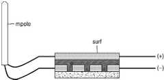
도 2는 본 발명의 일 실시예에 따른 하이브리드 안테나의 구성을 개략적으로 나타내는 도면이다.2 is a view schematically showing a configuration of a hybrid antenna according to an embodiment of the present invention.
도 2를 참조하면, 본 발명의 일 실시예에 따른 하이브리드 안테나는 모노폴 안테나(monopole antenna, 이하 mpole)와 표면파 안테나(surface wave antenna, 이하 surf)를 포함하며, 상기 모노폴 안테나(mpole)와 상기 표면파 안테나(surf)는 서로 병렬로 연결된다.2, a hybrid antenna according to an embodiment of the present invention includes a monopole antenna (hereinafter referred to as a " mpole ") and a surface wave antenna The antennas are connected in parallel with each other.
상기 모노폴 안테나(mpole)는 일반적인 모노폴 안테나로 이해할 수 있으며, 무한한 대지면이나 완전도체에 수직으로 세워지는 모노폴의 길이가 약 1/4 파장일 때 공진하는 특성을 이용하는 안테나이다.The monopole antenna can be understood as a general monopole antenna, and is an antenna using resonance characteristics when the length of a monopole vertically installed on an infinite ground plane or a perfect conductor is about 1/4 wavelength.
상기 표면파 안테나(surf)는 금속 벽에 설치되어 상기 금속 벽을 타고 흐르는 표면 전자기파(evanescent electromagnetic wave)를 송신하거나, 상기 금속 벽을 따라 흐르는 표면 전자기파를 수신할 수 있다. 상기 표면파 안테나(surf)의 보다 구체적인 구조와 동작 원리는 후속 도면들을 참조로 하여 설명하도록 한다.The surface wave antenna may be mounted on a metal wall to transmit an evanescent electromagnetic wave flowing through the metal wall or receive surface electromagnetic waves flowing along the metal wall. A more detailed structure and operation principle of the surface wave antenna (surf) will be described with reference to the following drawings.
도 3은 본 발명의 일 실시예에 따른 표면파 안테나로 형성되는 무선 전력 전송 시스템 및 통신 시스템의 구성을 개략적으로 나타내는 도면이다.3 is a diagram schematically illustrating a configuration of a wireless power transmission system and a communication system formed by a surface wave antenna according to an embodiment of the present invention.
도 3을 참조하면, 본 발명의 일 실시예에 따른 표면파 안테나로 형성되는 통신 시스템은 송신부(100’) 및 수신부(200’)를 포함한다. 송신부(100’)와 수신부(200’)는 제어 룸(control room)과 엔진 룸(engine room) 및 펌프 룸(pump room)과 같이 복수의 공간을 가진 배, 또는 컨테이너 등과 같은 차폐된 각각의 상이한 공간에 설치되어 전력 또는 데이터를 주고 받을 수 있다.Referring to FIG. 3, a communication system formed by a surface wave antenna according to an embodiment of the present invention includes a transmitter 100 'and a receiver 200'. The transmitting unit 100 'and the receiving unit 200' may include a control room, an engine room, and a pump room, each of which is shielded, such as a ship having a plurality of spaces, And can be installed in a space to exchange power or data.
송신부(100’)와 수신부(200’)는 각각 본 발명의 일 실시예에 따른 표면파 안테나로 구성되며, 송신부(100’)에 포함되는 표면파 안테나는 금속 벽(300)에 부착되어 상기 금속 벽을 타고 흐르는 표면 전자기파를 송신할 수 있다. 또한, 수신부(200’)에 포함되는 표면파 안테나는 금속 벽에 부착되어 상기 금속 벽을 타고 흐르는 표면 전자기파를 수신할 수 있다.The surface wave antenna included in the transmitter 100 'may be attached to the
도 4는 본 발명의 일 실시예에 따른 표면파 안테나의 구조를 개략적으로 나타내는 도면이다.4 is a view schematically showing the structure of a surface wave antenna according to an embodiment of the present invention.
도 4를 참조하면, 본 발명의 일 실시예에 따른 표면파 안테나는 상부층(10), 중간층(20) 및 하부층(30)을 포함한다. 상부층(10)은 박막의 도파관으로 사각모양으로, 내부에 복수의 천공된 사각모양의 사각홀(11)이 형성되어 그물망 형태를 가진다.Referring to FIG. 4, a surface wave antenna according to an embodiment of the present invention includes an
상부층(10)은 구리 재질로 이루어질 수 있으나, 반드시 구리로 한정되는 것은 아니며, 다른 전도성 물질로 이루어질 수 있다.The
중간층(20)은 유전체 층으로 상부층(10)과 동일한 두께를 가지며, 탄소 섬유나 폴리카보네이트(PC)로 이루어질 수 있다. 하부층(30)은 상부층(10)과 크기(길이, 너비, 및 두께)가 동일하고, 접지 기능을 한다.The
상부층(10), 중간층(20) 및 하부층(30)으로 구성되는 상기 표면파 안테나는 상술한 바와 같이, 배 또는 컨테이너의 차폐된 공간의 두꺼운 금속 벽에 설치되며, 20MHz~150MHz 범위의 주파수를 가진 표면 전자기파를 발생시킨다.The surface acoustic wave antenna constituted by the
도 5 내지 도 7은 본 발명의 일 실시예에 따른 무선 전력 전송 시스템 및 통신 시스템의 송신부와 수신부의 구성을 개략적으로 나타내는 도면이다.5 to 7 are views schematically showing a configuration of a transmitter and a receiver of a wireless power transmission system and a communication system according to an embodiment of the present invention.
먼저, 도 5를 참조하면, 본 발명의 일 실시예에 따른 무선 전력 전송 시스템 및 통신 시스템(100)은 송신부(110)와 수신부(120)를 포함한다. 송신부(110)는 금속 벽에 설치되어 상기 금속 벽의 표면을 따라 흐르는 표면 전자기파를 송신하는 제1 표면파 안테나(surf 1) 및 상기 제1 표면파 안테나(surf 1)와 병렬로 연결되는 제1 모노폴 안테나(mpole 1)를 포함한다.Referring to FIG. 5, a wireless power transmission system and a
그리고, 수신부(120)는 송신부(110)에서 송신되는 전파를 수신하는 제2 모노폴 안테나(mpole 2)를 포함한다.The
도 1을 참조로 하여 설명한 바와 같은 선박의 선실에 도 5의 송신부(110)와 같이 제1 표면파 안테나(surf 1)와 제1 모노폴 안테나(mpole 1)를 포함하는 송신기가 설치되어 있는 경우, 상기 선실과 분리된 다른 선실에 위치하는 선원은 도 5의 제2 모노폴 안테나(mpole 2)를 포함하는 수신부(120)를 이용하여, 상기 송신부(110)가 설치되어 있는 상기 선실에 위치하는 선원과 통신할 수 있다.When a transmitter including a first surface wave antenna (surf 1) and a first monopole antenna (mpole 1) is installed in a cabin of a ship as described with reference to FIG. 1, like the
제1 모노폴 안테나(mpole 1)에서 출력되는 전자기파는 제2 모노폴 안테나(mpole 2)이 수신할 수 있음은 자명하며, 제1 표면파 안테나(surf 1)에서 출력되는 표면 전자기파는 상기 금속 벽을 따라 흐르다가 굴곡에서 공기중으로 퍼질 수 있으며 제2 모노폴 안테나(mpole 2)는 이러한 전자기파를 수신하는 것으로 이해할 수 있다.It is apparent that the electromagnetic wave output from the first monopole antenna mpole 1 can be received by the second monopole antenna mpole 2 and surface electromagnetic waves output from the first surface wave antenna surf 1 flow along the metal wall And the second monopole antenna (mpole 2) can be understood to receive such electromagnetic waves.
또한, 송신부(110)와 수신부(120)는 반드시 신호 및/또는 전력을 보내고 받는 역할로 한정되지 않으며, 서로 양방향 통신을 수행할 수 있다. 즉, 제2 모노폴 안테나(mpole 2)에서 출력되는 전자기파는 제1 모노폴 안테나(mpole 1) 및/또는 제1 표면파 안테나(surf 1)에 의해 수신될 수 있다.Also, the transmitting
도 6에 도시되는 무선 전력 전송 시스템 및 통신 시스템(200)은, 도 5를 참조로 하여 설명한 무선 전력 전송 시스템 및 통신 시스템(100)과 마찬가지로 송신부(210)와 수신부(220)를 포함한다.The wireless power transmission system and
송신부(210)는 도 5를 참조로 하여 설명한 송신부(110)와 동일하게 제1 표면파 안테나(surf 1)와 제1 모노폴 안테나(mpole 1)를 포함한다. 그리고, 수신부(220)는 제2 표면파 안테나(surf 2)를 포함한다.The transmitting
제1 표면파 안테나(surf 1) 및/또는 제1 모노폴 안테나(mpole 1)에서 출력되는 전자기파는 상기 금속 벽 및/또는 공기를 통해 전달되며, 수신부(220)에 포함되는 제2 표면파 안테나(surf 2)는 상기 전자기파를 수신할 수 있다.The electromagnetic waves output from the first surface wave antenna surf 1 and / or the first monopole antenna (mpole 1) are transmitted through the metal wall and / or air, and the second surface wave antenna surf 2 Can receive the electromagnetic wave.
제1 표면파 안테나(surf 1)에서 생성되어 상기 금속 벽을 타고 흐르는 표면 전자기파는 도 1 내지 도 4를 참조로 하여 설명한 바와 같이, 수신부(220)에 포함되는 제2 표면파 안테나(surf 2)가 수신할 수 있다. 또한, 제1 모노폴 안테나(mpole 1)에서 생성되어 공기를 통해 전달되는 전자기파도 제2 표면파 안테나(surf 2)에 의해 수신될 수 있다.As described above with reference to FIGS. 1 to 4, the surface electromagnetic wave generated by the first surface wave antenna surf 1 and flowing through the metal wall is received by the second surface wave antenna surf 2 included in the receiving unit 220, can do. Also, an electromagnetic wave generated in the first monopole antenna (mpole 1) and transmitted through the air can also be received by the second surface wave antenna (surf 2).
도 6에 도시되는 송신부(210)와 수신부(220)는 반드시 신호 및/또는 전력을 보내고 받는 역할로 한정되지 않으며, 서로 양방향 통신을 수행할 수 있다. 즉, 제2 표면파 안테나(surf 2)에서 출력되는 전자기파는 제1 모노폴 안테나(mpole 1) 및/또는 제1 표면파 안테나(surf 1)에 의해 수신될 수 있다.The transmitting
도 7에 도시되는 무선 전력 전송 시스템 및 통신 시스템(300)은, 도 5를 참조로 하여 설명한 무선 전력 전송 시스템 및 통신 시스템(100)과 마찬가지로 송신부(310)와 수신부(320)를 포함한다.The wireless power transmission system and
송신부(310)는 도 5를 참조로 하여 설명한 송신부(110)와 동일하게 제1 표면파 안테나(surf 1)와 제1 모노폴 안테나(mpole 1)를 포함한다. 그리고, 수신부(320)는 제2 표면파 안테나(surf 2) 및 제2 모노폴 안테나(mpole 2)를 포함한다.The transmitting
제1 표면파 안테나(surf 1) 및/또는 제1 모노폴 안테나(mpole 1)에서 출력되는 전자기파는 상기 금속 벽 및/또는 공기를 통해 전달되며, 수신부(320)에 포함되는 제2 표면파 안테나(surf 2) 및 제2 모노폴 안테나(mpole 2)는 상기 전자기파를 수신할 수 있다.The electromagnetic waves output from the first surface wave antenna surf 1 and / or the first monopole antenna (mpole 1) are transmitted through the metal wall and / or air, and the second surface wave antenna surf 2 And the second monopole antenna (mpole 2) may receive the electromagnetic waves.
제1 표면파 안테나(surf 1)에서 생성되어 상기 금속 벽을 타고 흐르는 표면 전자기파는 도 1 내지 도 4를 참조로 하여 설명한 바와 같이, 수신부(320)에 포함되는 제2 표면파 안테나(surf 2)가 수신할 수 있다. 또한, 제1 모노폴 안테나(mpole 1)에서 생성되어 공기를 통해 전달되는 전자기파는 제2 모노폴 안테나(mpole 2)에 의해 수신될 수 있다.As described above with reference to FIGS. 1 to 4, the surface electromagnetic wave generated by the first surface wave antenna surf 1 and flowing through the metal wall is received by the second surface wave antenna surf 2 included in the
도 7에 도시되는 송신부(310)와 수신부(320)는 반드시 신호 및/또는 전력을 보내고 받는 역할로 한정되지 않으며, 서로 양방향 통신을 수행할 수 있다. 즉, 제2 표면파 안테나(surf 2) 및 제2 모노폴 안테나(mpole 2)에서 출력되는 전자기파는 제1 모노폴 안테나(mpole 1) 및 제1 표면파 안테나(surf 1)에 의해 수신될 수 있다.The transmitting
도 8은 본 발명의 다른 실시예에 따른 리피터가 설치되는 위치를 예시적으로 나타내는 도면이다.8 is a view illustrating an exemplary location of a repeater according to another embodiment of the present invention.
본 발명의 다른 실시예에 따른 무선 전력 전송 시스템 및 통신 시스템은 송신부와 수신부 사이에 상기 송신부와 상기 수신부를 중계하는 리피터를 더 포함할 수 있다.The wireless power transmission system and the communication system according to another embodiment of the present invention may further include a repeater for relaying the transmitter and the receiver between the transmitter and the receiver.
상기 리피터는 상기 금속 벽의 표면을 따라 흐르는 표면 전자기파를 송수신하는 제3 표면파 안테나 및 상기 제3 표면파 안테나와 병렬로 연결되는 제3 모노폴 안테나를 포함할 수 있다.The repeater may include a third surface wave antenna that transmits and receives surface electromagnetic waves flowing along the surface of the metal wall, and a third monopole antenna that is connected in parallel with the third surface wave antenna.
본 발명에 따른 무선 전력 전송 시스템 및 통신 시스템이 대형 선박에 적용되는 경우, 송신부와 수신부 사이의 거리가 멀수록 전력 및/또는 전파 전송 효율이 떨어질 수 있다.When the wireless power transmission system and the communication system according to the present invention are applied to a large-sized ship, the power and / or radio wave transmission efficiency may decrease as the distance between the transmitter and the receiver increases.
상기 리피터는 이러한 문제를 방지하기 위하여 상기 송신부와 상기 수신부 사이에서 전력 및/또는 전파를 중계하는 기능을 수행할 수 있다.The repeater may perform a function of relaying power and / or radio waves between the transmitter and the receiver in order to prevent such a problem.
도 8에서 선실 1과 선실 3 사이의 거리가 멀어 전력 및/또는 전파 전송 효율이 떨어지는 경우, 선실 2에 상기 리피터를 설치할 수 있으며, 상기 리피터는 선실 1에서 선실 3으로 전송되는 전력 및/또는 전파를 중계하거나, 선실 3에서 선실 1로 전송되는 전력 및/또는 전파를 중계할 수 있다.8, it is possible to install the repeater in the cabin 2 when the distance between the cabin 1 and the cabin 3 is too great to reduce power and / or radio wave transmission efficiency, Or relay the electric power and / or radio waves transmitted from the cabin 3 to the cabin 1.
도 9는 본 발명의 또 다른 실시예에 따른 무선 전력 전송 시스템 및 통신 시스템의 구성을 개략적으로 나타내는 도면이다.9 is a diagram schematically showing a configuration of a wireless power transmission system and a communication system according to another embodiment of the present invention.
도 9를 참조하면, 본 발명의 또 다른 실시예에 따른 무선 전력 전송 시스템 및 통신 시스템(400)은 전원 공급부(430) 및 임피던스 정합부(440)를 더 포함한다. 상기 송신부에 전력을 공급하는 전원 공급부(430)는 송신부(410)에 전력을 공급하며, 임피던스 정합부(440)는 송신부(410)에서 반사된 전압을 측정하여 기준 전압과 크기를 비교하고, 비교 결과에 따라 임피던스 정합을 수행한다.Referring to FIG. 9, the wireless power transmission system and
그리고, 전원 공급부(430)는 임피던스 정합된 전압을 송신부(410)에 제공한다.The
송신부(410)에 임피던스 정합된 전압을 공급함으로써, 무선 전력 전송 시스템 및 통신 시스템(400)은 전력 및/또는 전파 전송 효율을 향상시킬 수 있으며, 공급 가능한 최대의 전력을 제공하는 효과를 얻을 수 있다.By supplying the impedance-matched voltage to the
한편, 전원 공급부(430)는 일반 모드 또는 급속 모드 중 어느 하나의 모드로 동작할 수 있으며, 상기 급속 모드에서 송신부(410)에 제공되는 전력의 크기는 상기 일반 모드에서 송신부(410)에 제공되는 전력의 크기보다 크게 제어될 수 있다.Meanwhile, the
무선 전력 전송 시스템 및 통신 시스템(400)을 통해 전력이 전송되는 경우, 상기 전력은 수신부(420)에 의해 수신되며, 수신된 상기 전력은 정류부를 통해 부하로 공급될 수 있다.When power is transmitted through the wireless power transmission system and the
상기 부하에 짧은 시간동안 많은 전력이 공급되어야 하는 경우, 전원 공급부(430)는 상기 급속 모드로 동작할 수 있으며, 이때 송신부(410)에 공급되는 전력의 크기는 상기 일반 모드에서 송신부(410)에 공급되는 전력의 크기보다 크게 제어될 수 있다.When a large amount of power is to be supplied to the load for a short time, the
한편, 전원 공급부(430)는 송신부(410)로부터 전원 및/또는 전파를 수신하는 장치의 개수에 비례하여 송신부(410)에 공급되는 전력의 크기를 크게 설정할 수 있다.Meanwhile, the
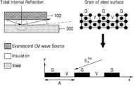
도 10은 본 발명에 따른 무선 전력 전송 시스템 및 통신 시스템의 전력 또는 데이터 전송 원리를 개략적으로 나타내는 도면이다.10 is a diagram schematically illustrating a principle of power or data transmission in a wireless power transmission system and a communication system according to the present invention.
도 10을 참조하면, 금속 벽은 융기된 부분(grain, G)과 함몰된 부분(void, V)을 포함하는 BCC(body centric cuboid crystal) 구조 또는 요철 구조로 이루어져 일정한 주기(A)를 가질 수 있다.10, the metal wall may have a BCC (body center cubic crystal) structure or a concavo-convex structure including a raised portion (grain, G) and a recessed portion (void, V) have.
표면 전자기파와 상기 금속 벽의 상호 작용으로 인해 표면파가 발생하여 상기 표면 전자기파가 상기 금속 벽의 표면을 흐르게 된다. 즉, 표면 전자기파 소스(Evanescent EM wave source)인 송신부에서 발생한 표면 전자기파는 상기 주기(A)에 따라 형성된 융기부(G)와 함몰부(V)에서 전반사를 일으켜 흐르게 된다.Surface waves are generated due to interaction between the surface electromagnetic wave and the metal wall, and the surface electromagnetic waves flow on the surface of the metal wall. In other words, the surface electromagnetic wave generated by the transmission unit, which is a surface electromagnetic wave source (Evanescent EM wave source), causes total reflection at the ridge G and the depression V formed according to the period A.
따라서, 상기 송신부가 장착된 금속 벽을 타고 흐르게 되는 상기 표면 전자기파는 상기 금속 벽에 설치되는 수신부를 통해 수신될 수 있다.Therefore, the surface electromagnetic wave flowing through the metal wall on which the transmitter is mounted can be received through the receiver installed on the metal wall.
본 발명에서 모든 예들 또는 예시적인 용어(예를 들어, 등등)의 사용은 단순히 본 발명을 상세히 설명하기 위한 것으로서 특허청구범위에 의해 한정되지 않는 이상 상기 예들 또는 예시적인 용어로 인해 본 발명의 범위가 한정되는 것은 아니다. 또한 해당 기술 분야의 통상의 기술자는 다양한 수정, 조합 및 변경이 부가된 특허청구범위 또는 그 균등물의 범주 내에서 설계 조건 및 팩터(factor)에 따라 구성될 수 있음을 알 수 있다.The use of all examples or exemplary language (e.g., etc.) in this invention is for the purpose of describing the present invention only in detail and is not intended to be limited by the scope of the claims, But is not limited thereto. It will also be appreciated by those skilled in the art that various modifications, combinations, and alterations may be made depending on design criteria and factors within the scope of the appended claims or equivalents thereof.
따라서, 본 발명의 사상은 상기 설명된 실시예에 국한되어 정해져서는 아니되며, 후술하는 특허청구범위뿐만 아니라, 이 특허청구범위와 균등한 또는 이로부터 등가적으로 변경된 모든 범위는 본 발명의 사상의 범주에 속한다고 할 것이다.Accordingly, the spirit of the present invention should not be construed as being limited to the above-described embodiments, and all ranges that are equivalent to or equivalent to the claims of the present invention as well as claims Category.
100, 200, 300, 400: 무선 전력 전송 시스템 및 통신 시스템
110, 210, 310, 410: 송신부
120, 220, 320, 420: 수신부
430: 전원 공급부
440: 임피던스 정합부100, 200, 300, 400: Wireless power transmission system and communication system
110, 210, 310, 410:
120, 220, 320, 420:
430: Power supply
440: Impedance matching portion
Claims (6)
Translated fromKorean상기 표면파 안테나와 병렬로 연결되는 모노폴 안테나
를 포함하고,
상기 표면파 안테나는,
전도성 물질로 구현되며, 복수의 천공된 홀 영역을 포함하는 도파관 구조를 갖는 상부층;
유전체로 구현되며, 상기 상부층과 동일한 두께를 갖는 중간층; 및
상기 상부층과 동일한 길이, 너비 및 두께를 갖고 접지 기능을 수행하는 하부층
을 포함하는 것을 특징으로 하는 하이브리드 안테나.A surface acoustic wave (SAW) antenna mounted on the metal wall and propagating electromagnetic waves through the metal wall; And
A monopole antenna connected in parallel with the surface wave antenna;
Lt; / RTI >
In the surface acoustic wave antenna,
An upper layer having a waveguide structure which is embodied as a conductive material and includes a plurality of perforated hole areas;
An intermediate layer which is embodied as a dielectric and has the same thickness as the upper layer; And
A lower layer having the same length, width and thickness as the upper layer and performing a grounding function
And a second antenna.
상기 전자기파는 일정한 주기에 따라 상기 금속 벽에 형성된 융기부와 함몰부에서 전반사를 일으켜 상기 금속 벽의 표면을 따라 흐르는 하이브리드 안테나.The method according to claim 1,
Wherein the electromagnetic wave propagates along the surface of the metal wall by causing total reflection at a ridge portion and a depression formed in the metal wall in a predetermined period.
상기 제1 표면파 안테나와 병렬로 연결되는 제1 모노폴 안테나;
상기 전자기파가 전파되도록 하는 전력을 공급하는 전원 공급부; 및
임피던스 정합부
를 포함하고,
상기 제1 표면파 안테나는,
전도성 물질로 구현되며, 복수의 천공된 홀 영역을 포함하는 도파관 구조를 갖는 상부층;
유전체로 구현되며, 상기 상부층과 동일한 두께를 갖는 중간층; 및
상기 상부층과 동일한 길이, 너비 및 두께를 갖고, 접지 기능을 수행하는 하부층
을 포함하는 것을 특징으로 하고,
상기 임피던스 정합부는 반사된 전압을 측정하여 기준 전압과 크기를 비교하고, 비교 결과에 따라 임피던스 정합을 수행하고, 상기 전원 공급부는 상기 임피던스 정합된 전압을 공급하는
통신 시스템.A first surface wave antenna installed on the metal wall and propagating the electromagnetic wave through the metal wall;
A first monopole antenna connected in parallel to the first surface wave antenna;
A power supply unit for supplying power to cause the electromagnetic wave to propagate; And
The impedance matching portion
Lt; / RTI >
Wherein the first surface acoustic wave antenna comprises:
An upper layer having a waveguide structure which is embodied as a conductive material and includes a plurality of perforated hole areas;
An intermediate layer which is embodied as a dielectric and has the same thickness as the upper layer; And
A lower layer having the same length, width and thickness as the upper layer and performing a grounding function,
, Wherein:
The impedance matching unit measures the reflected voltage and compares the reference voltage with the magnitude, and performs impedance matching according to the comparison result. The power supply unit supplies the impedance-matched voltage
Communication system.
송신 장치와 수신 장치를 중계하는 리피터;
를 더 포함하고,
상기 리피터는 상기 금속 벽을 통해 전파되는 전자기파를 송수신하는 제2 표면파 안테나 및 상기 제2 표면파 안테나와 병렬로 연결되는 제2 모노폴 안테나를 포함하는 통신 시스템.The method of claim 3,
A repeater for relaying the transmitting device and the receiving device;
Further comprising:
Wherein the repeater comprises a second surface wave antenna for transmitting and receiving electromagnetic waves propagated through the metal wall and a second monopole antenna connected in parallel with the second surface wave antenna.
상기 전원 공급부는 일반 모드 및 급속 모드 중 어느 하나로 동작하고, 상기 급속 모드에서 공급하는 제1 전력의 크기는 상기 일반 모드에서 공급하는 제2 전력의 크기보다 큰 통신 시스템.5. The method of claim 4,
Wherein the power supply unit operates in one of a normal mode and a rapid mode and a magnitude of a first power supplied in the rapid mode is greater than a magnitude of a second power supplied in the normal mode.
Priority Applications (4)
| Application Number | Priority Date | Filing Date | Title |
|---|---|---|---|
| KR1020160076613AKR101804683B1 (en) | 2016-06-20 | 2016-06-20 | Wireless Power Transmission System and Communication System |
| CN201680088443.8ACN109891707A (en) | 2016-06-20 | 2016-12-29 | Wireless power transmission system and communication system |
| PCT/KR2016/015497WO2017222133A1 (en) | 2016-06-20 | 2016-12-29 | Wireless power transmission system and communication system |
| US16/310,790US10797399B2 (en) | 2016-06-20 | 2016-12-29 | Wireless power transmission system and communication system |
Applications Claiming Priority (1)
| Application Number | Priority Date | Filing Date | Title |
|---|---|---|---|
| KR1020160076613AKR101804683B1 (en) | 2016-06-20 | 2016-06-20 | Wireless Power Transmission System and Communication System |
Publications (1)
| Publication Number | Publication Date |
|---|---|
| KR101804683B1true KR101804683B1 (en) | 2017-12-05 |
Family
ID=60784179
Family Applications (1)
| Application Number | Title | Priority Date | Filing Date |
|---|---|---|---|
| KR1020160076613AActiveKR101804683B1 (en) | 2016-06-20 | 2016-06-20 | Wireless Power Transmission System and Communication System |
Country Status (4)
| Country | Link |
|---|---|
| US (1) | US10797399B2 (en) |
| KR (1) | KR101804683B1 (en) |
| CN (1) | CN109891707A (en) |
| WO (1) | WO2017222133A1 (en) |
Cited By (1)
| Publication number | Priority date | Publication date | Assignee | Title |
|---|---|---|---|---|
| KR102854515B1 (en) | 2024-10-18 | 2025-09-03 | (주)천우테크 | System for wireless transmitting of metal surface wave employing image signal transmitting for inner nspecting of metal pipe |
Families Citing this family (3)
| Publication number | Priority date | Publication date | Assignee | Title |
|---|---|---|---|---|
| KR102630057B1 (en)* | 2018-08-10 | 2024-01-25 | 엘지전자 주식회사 | Wireless power transreceiver, and image display apparatus including the same |
| KR102629015B1 (en)* | 2021-09-03 | 2024-01-25 | 주식회사 지엔테크놀로지스 | Method and system for metal shielding spaces management using multiple terminals |
| JPWO2023119429A1 (en)* | 2021-12-21 | 2023-06-29 |
Citations (1)
| Publication number | Priority date | Publication date | Assignee | Title |
|---|---|---|---|---|
| KR100660051B1 (en)* | 2005-08-11 | 2006-12-22 | 코마테크 주식회사 | Broadband Monopole Antenna Structure |
Family Cites Families (10)
| Publication number | Priority date | Publication date | Assignee | Title |
|---|---|---|---|---|
| US6366254B1 (en)* | 2000-03-15 | 2002-04-02 | Hrl Laboratories, Llc | Planar antenna with switched beam diversity for interference reduction in a mobile environment |
| US20090284369A1 (en) | 2008-05-13 | 2009-11-19 | Qualcomm Incorporated | Transmit power control for a wireless charging system |
| KR101015055B1 (en)* | 2008-08-01 | 2011-02-16 | 한국전기연구원 | Wireless power transmitter and method using waveguide of surface wave |
| JP5681947B2 (en)* | 2009-08-13 | 2015-03-11 | パナソニックIpマネジメント株式会社 | WIRELESS POWER TRANSMISSION DEVICE, AND GENERATION DEVICE AND GENERATION SYSTEM INCLUDING WIRELESS POWER TRANSMISSION DEVICE |
| KR100962593B1 (en)* | 2010-02-16 | 2010-06-11 | 동국대학교 산학협력단 | Method and apparatus for area based control of vacuum cleaner, and recording medium thereof |
| CN201812921U (en)* | 2010-06-17 | 2011-04-27 | 惠州市硕贝德通讯科技有限公司 | High-gain reduced surface-wave antenna |
| KR20120095144A (en)* | 2011-02-18 | 2012-08-28 | 이상재 | Removable belt loop automatic cutting machine |
| EP3017504B1 (en)* | 2013-07-03 | 2018-09-26 | HRL Laboratories, LLC | Electronically steerable, artificial impedance, surface antenna |
| KR101533155B1 (en)* | 2013-09-24 | 2015-07-02 | 한양대학교 산학협력단 | Antenna for Wearable Device |
| US8897697B1 (en) | 2013-11-06 | 2014-11-25 | At&T Intellectual Property I, Lp | Millimeter-wave surface-wave communications |
- 2016
- 2016-06-20KRKR1020160076613Apatent/KR101804683B1/enactiveActive
- 2016-12-29USUS16/310,790patent/US10797399B2/enactiveActive
- 2016-12-29CNCN201680088443.8Apatent/CN109891707A/enactivePending
- 2016-12-29WOPCT/KR2016/015497patent/WO2017222133A1/ennot_activeCeased
Patent Citations (1)
| Publication number | Priority date | Publication date | Assignee | Title |
|---|---|---|---|---|
| KR100660051B1 (en)* | 2005-08-11 | 2006-12-22 | 코마테크 주식회사 | Broadband Monopole Antenna Structure |
Cited By (1)
| Publication number | Priority date | Publication date | Assignee | Title |
|---|---|---|---|---|
| KR102854515B1 (en) | 2024-10-18 | 2025-09-03 | (주)천우테크 | System for wireless transmitting of metal surface wave employing image signal transmitting for inner nspecting of metal pipe |
Also Published As
| Publication number | Publication date |
|---|---|
| WO2017222133A1 (en) | 2017-12-28 |
| US20190214734A1 (en) | 2019-07-11 |
| US10797399B2 (en) | 2020-10-06 |
| CN109891707A (en) | 2019-06-14 |
Similar Documents
| Publication | Publication Date | Title |
|---|---|---|
| KR101804683B1 (en) | Wireless Power Transmission System and Communication System | |
| US9882606B2 (en) | Hybrid guided surface wave communication | |
| US20180226187A1 (en) | Signal and power transmission system | |
| JP6471382B2 (en) | Magnetic wave antenna and magnetic wave communication apparatus using the same | |
| EP1234353B1 (en) | Electromagnetic field in a communications system for wireless networks | |
| US12261374B2 (en) | Antenna structure and electronic device | |
| CN109309521A (en) | A kind of RTK base station apparatus, signal interaction system and method | |
| US12273735B2 (en) | Apparatus, methods and systems for improving coverage of wireless communication networks | |
| CN108494430A (en) | A kind of miniaturization mm wave RF front end | |
| US10101444B2 (en) | Remote surface sensing using guided surface wave modes on lossy media | |
| JP5243213B2 (en) | Electromagnetic wave interface device and signal transmission system using the same | |
| CN108140139B (en) | Container tracking system | |
| CN207134465U (en) | Communication apparatus multifrequency transmitting antenna | |
| KR102611108B1 (en) | Patch antenna of surface wave and apparatus of wireless communication using the antenna | |
| US20110109408A1 (en) | Electromagnetic coupler and communication apparatus using the same | |
| WO2016170769A1 (en) | Wireless power supply system and wireless power supply method | |
| CN102843171A (en) | Communication apparatus | |
| CN105470636A (en) | Double-frequency high-isolation multiple input multiple output (MIMO) directional antenna applied to wireless local area network (WLAN) | |
| JP6132971B2 (en) | Rotating polarization antenna, transceiver module, elevator control system and substation control system | |
| Mimura et al. | Experimental Validation of an Extended Pseudo-Scale Model for Air-Brackish Two-Layer Problem | |
| US20240250741A1 (en) | Communication via Uplink and Downlink Reflective Devices | |
| JP2005150334A (en) | Electromagnetic wave transmissive housing | |
| WO2006070844A1 (en) | Communication system | |
| CN103746174B (en) | Plate carries the 510MHz radio-frequency module of PCB antenna | |
| CN103746172B (en) | Plate carries the 855MHz radio-frequency module of PCB antenna |
Legal Events
| Date | Code | Title | Description |
|---|---|---|---|
| PA0109 | Patent application | St.27 status event code:A-0-1-A10-A12-nap-PA0109 | |
| PA0201 | Request for examination | St.27 status event code:A-1-2-D10-D11-exm-PA0201 | |
| R17-X000 | Change to representative recorded | St.27 status event code:A-3-3-R10-R17-oth-X000 | |
| PE0902 | Notice of grounds for rejection | St.27 status event code:A-1-2-D10-D21-exm-PE0902 | |
| E13-X000 | Pre-grant limitation requested | St.27 status event code:A-2-3-E10-E13-lim-X000 | |
| P11-X000 | Amendment of application requested | St.27 status event code:A-2-2-P10-P11-nap-X000 | |
| P13-X000 | Application amended | St.27 status event code:A-2-2-P10-P13-nap-X000 | |
| E701 | Decision to grant or registration of patent right | ||
| PE0701 | Decision of registration | St.27 status event code:A-1-2-D10-D22-exm-PE0701 | |
| GRNT | Written decision to grant | ||
| PR0701 | Registration of establishment | St.27 status event code:A-2-4-F10-F11-exm-PR0701 | |
| PR1002 | Payment of registration fee | St.27 status event code:A-2-2-U10-U11-oth-PR1002 Fee payment year number:1 | |
| PG1601 | Publication of registration | St.27 status event code:A-4-4-Q10-Q13-nap-PG1601 | |
| R18-X000 | Changes to party contact information recorded | St.27 status event code:A-5-5-R10-R18-oth-X000 | |
| R18-X000 | Changes to party contact information recorded | St.27 status event code:A-5-5-R10-R18-oth-X000 | |
| PR1001 | Payment of annual fee | St.27 status event code:A-4-4-U10-U11-oth-PR1001 Fee payment year number:4 | |
| P22-X000 | Classification modified | St.27 status event code:A-4-4-P10-P22-nap-X000 | |
| PR1001 | Payment of annual fee | St.27 status event code:A-4-4-U10-U11-oth-PR1001 Fee payment year number:5 | |
| PR1001 | Payment of annual fee | St.27 status event code:A-4-4-U10-U11-oth-PR1001 Fee payment year number:6 | |
| R18-X000 | Changes to party contact information recorded | St.27 status event code:A-5-5-R10-R18-oth-X000 | |
| PR1001 | Payment of annual fee | St.27 status event code:A-4-4-U10-U11-oth-PR1001 Fee payment year number:7 | |
| P22-X000 | Classification modified | St.27 status event code:A-4-4-P10-P22-nap-X000 | |
| R18-X000 | Changes to party contact information recorded | St.27 status event code:A-5-5-R10-R18-oth-X000 | |
| PR1001 | Payment of annual fee | St.27 status event code:A-4-4-U10-U11-oth-PR1001 Fee payment year number:8 | |
| PR1001 | Payment of annual fee | St.27 status event code:A-4-4-U10-U11-oth-PR1001 Fee payment year number:9 |