KR101803540B1 - Piezo driving circuit and driving method thereof - Google Patents
Piezo driving circuit and driving method thereofDownload PDFInfo
- Publication number
- KR101803540B1 KR101803540B1KR1020120088636AKR20120088636AKR101803540B1KR 101803540 B1KR101803540 B1KR 101803540B1KR 1020120088636 AKR1020120088636 AKR 1020120088636AKR 20120088636 AKR20120088636 AKR 20120088636AKR 101803540 B1KR101803540 B1KR 101803540B1
- Authority
- KR
- South Korea
- Prior art keywords
- gate
- pwm output
- switch
- period
- control signal
- Prior art date
- Legal status (The legal status is an assumption and is not a legal conclusion. Google has not performed a legal analysis and makes no representation as to the accuracy of the status listed.)
- Active
Links
- 238000000034methodMethods0.000titleclaimsabstractdescription28
- 239000003990capacitorSubstances0.000description17
- 230000007423decreaseEffects0.000description10
- 238000010586diagramMethods0.000description10
- 239000000872bufferSubstances0.000description4
- 238000007599dischargingMethods0.000description3
- 230000003071parasitic effectEffects0.000description2
Images


Classifications
- H—ELECTRICITY
- H02—GENERATION; CONVERSION OR DISTRIBUTION OF ELECTRIC POWER
- H02N—ELECTRIC MACHINES NOT OTHERWISE PROVIDED FOR
- H02N2/00—Electric machines in general using piezoelectric effect, electrostriction or magnetostriction
- H02N2/10—Electric machines in general using piezoelectric effect, electrostriction or magnetostriction producing rotary motion, e.g. rotary motors
- H02N2/14—Drive circuits; Control arrangements or methods
- H—ELECTRICITY
- H02—GENERATION; CONVERSION OR DISTRIBUTION OF ELECTRIC POWER
- H02N—ELECTRIC MACHINES NOT OTHERWISE PROVIDED FOR
- H02N2/00—Electric machines in general using piezoelectric effect, electrostriction or magnetostriction
- H02N2/02—Electric machines in general using piezoelectric effect, electrostriction or magnetostriction producing linear motion, e.g. actuators; Linear positioners ; Linear motors
- H02N2/06—Drive circuits; Control arrangements or methods
- H02N2/065—Large signal circuits, e.g. final stages
- H02N2/067—Large signal circuits, e.g. final stages generating drive pulses
- H—ELECTRICITY
- H03—ELECTRONIC CIRCUITRY
- H03K—PULSE TECHNIQUE
- H03K17/00—Electronic switching or gating, i.e. not by contact-making and –breaking
- H03K17/16—Modifications for eliminating interference voltages or currents
- H03K17/161—Modifications for eliminating interference voltages or currents in field-effect transistor switches
- H03K17/162—Modifications for eliminating interference voltages or currents in field-effect transistor switches without feedback from the output circuit to the control circuit
- H—ELECTRICITY
- H03—ELECTRONIC CIRCUITRY
- H03K—PULSE TECHNIQUE
- H03K7/00—Modulating pulses with a continuously-variable modulating signal
- H03K7/08—Duration or width modulation ; Duty cycle modulation
- H—ELECTRICITY
- H10—SEMICONDUCTOR DEVICES; ELECTRIC SOLID-STATE DEVICES NOT OTHERWISE PROVIDED FOR
- H10N—ELECTRIC SOLID-STATE DEVICES NOT OTHERWISE PROVIDED FOR
- H10N30/00—Piezoelectric or electrostrictive devices
- H10N30/80—Constructional details
- H10N30/802—Circuitry or processes for operating piezoelectric or electrostrictive devices not otherwise provided for, e.g. drive circuits
- H—ELECTRICITY
- H03—ELECTRONIC CIRCUITRY
- H03K—PULSE TECHNIQUE
- H03K2217/00—Indexing scheme related to electronic switching or gating, i.e. not by contact-making or -breaking covered by H03K17/00
- H03K2217/0045—Full bridges, determining the direction of the current through the load
Landscapes
- Inverter Devices (AREA)
Abstract
Translated fromKoreanDescription
Translated fromKorean본 발명은 피에조 회로를 구동하는 피에조 구동 회로 및 피에조 구동 회로의 구동 방법에 관한 것이다.The present invention relates to a piezo driving circuit for driving a piezo circuit and a driving method for the piezo driving circuit.
피에조(Piezo) 회로는 전기적 에너지를 기계적 에너지로 변환하고, 또 기계적 에너지를 전기적 에너지로 변환할 수 있다. 피에조 회로를 구동하기 위해 풀브릿지 구동 회로가 사용된다.Piezo circuits can convert electrical energy into mechanical energy, and mechanical energy into electrical energy. A full bridge drive circuit is used to drive the piezo circuit.
풀브릿지 구동 회로는 피에조 회로에 구형파 형태의 전압을 공급한다. 예를 들어, 풀브릿지 구동 회로가 피에조 회로에 양의 방향(positive direction)으로 제1 직류전압을 공급하고, 음의 방향(negative direction)으로 제1 직류전압을 공급한다. 따라서 피에조 회로에 공급되는 구형파의 피크대피크(peak-to-peak) 전압은 제1 직류전압의 두 배가 된다.The full bridge drive circuit supplies a square wave voltage to the piezo circuit. For example, a full bridge drive circuit supplies a first DC voltage in a positive direction to a piezo circuit and a first DC voltage in a negative direction. Therefore, the peak-to-peak voltage of the square wave supplied to the piezo circuit is twice the first DC voltage.
이 때, 양의 방향으로 피에조 회로에 제1 직류전압이 공급되면 피에조 회로를 충전시키는 전류가 흐르고, 음의 방향으로 피에조 회로에 제1 직류전압이 공급되면 피에조 회로를 방전시키는 전류가 흐른다. 이렇게 발생하는 충전 전류 및 방전 전류의 대부분은 피에조 회로를 구성하는 커패시터를 충전 및 방전하는데 사용된다. 즉, 피에조 회로에 공급되는 전압의 방향이 바뀔 때 마다, 피에조 회로의 커패시터를 충전 또는 방전시키는 피크 전류가 발생한다.At this time, when the first DC voltage is supplied to the piezo circuit in the positive direction, a current for charging the piezo circuit flows, and when the first DC voltage is supplied to the piezo circuit in the negative direction, a current for discharging the piezo circuit flows. Most of the charging current and discharging current are used to charge and discharge the capacitors constituting the piezo circuit. That is, every time the direction of the voltage supplied to the piezo circuit changes, a peak current is generated which charges or discharges the capacitor of the piezo circuit.
그러면, 커패시터의 충전 및 방전에 따른 소비 전력의 증가와 소음의 증가가 문제된다.Then, the power consumption and the noise increase due to the charging and discharging of the capacitor are problematic.
본 발명의 실시 예를 통하여 피크 전류를 감소시킬 수 있는 피에조 구동 회로 및 피에조 구동 회로의 구동 방법을 제공하고자 한다.It is intended to provide a piezo driving circuit and a driving method of a piezo driving circuit capable of reducing a peak current through embodiments of the present invention.
본 발명의 실시 예에 따른 피에조 구동 회로는, 피에조 회로의 일단에 연결되어 있는 제1 및 제3 스위치, 상기 피에조 회로의 타단에 연결되어 있는 제2 및 제4 스위치를 포함하는 풀-브릿지 회로, 및 상기 제1 내지 제4 스위치의 스위칭 동작을 제어하는 스위치 제어부를 포함한다.A piezo driving circuit according to an embodiment of the present invention includes a full bridge circuit including first and third switches connected to one end of a piezo circuit, second and fourth switches connected to the other end of the piezo circuit, And a switch control unit for controlling switching operations of the first to fourth switches.
상기 스위치 제어부는, 스위칭 주파수를 제어하는 램프 신호와 피에조 전압의 주기를 제어하는 기준 정현파를 비교한 결과에 따라 제1 PWM 출력을 생성하고, 상기 램프 신호와 상기 기준 정현파가 반전된 반전 기준 정현파를 비교한 결과에 따라 제2 PWM 출력을 생성한다.The switch control unit generates a first PWM output according to a result of comparison between a ramp signal for controlling the switching frequency and a reference sinusoidal wave for controlling the period of the piezoelectric voltage, and outputs the inverted reference sinusoidal wave with the ramp signal and the reference sinusoidal wave inverted And generates a second PWM output according to the comparison result.
상기 스위치 제어부는, 상기 기준 정현파 및 상기 반전 기준 정현파의 제1 주기 동안 상기 제1 PWM 출력에 따라 상기 제1 및 제3 스위치의 스위칭 동작을 제어하고, 상기 제2 PWM 출력에 따라 상기 제2 및 제4 스위치의 스위칭 동작을 제어한다.Wherein the switch control unit controls the switching operation of the first and third switches according to the first PWM output during a first period of the reference sine wave and the inverted reference sine wave, And controls the switching operation of the fourth switch.
상기 스위치 제어부는, 다음 제2 주기 동안 상기 제2 PWM 출력에 따라 상기 제1 및 제3 스위치의 스위칭 동작을 제어하고, 상기 제1 PWM 출력에 따라 상기 제2 및 제4 스위치의 스위칭 동작을 제어한다.Wherein the switch control section controls the switching operation of the first and third switches according to the second PWM output for the next second period and controls the switching operation of the second and fourth switches in accordance with the first PWM output do.
상기 제1 스위치는, 직류 전압과 상기 피에조 회로의 일단 사이에 연결되어있고, 상기 제2 스위치는 상기 직류 전압과 상기 피에조 회로의 타단 사이에 연결되어 있으며, 상기 제3 스위치는 상기 피에조 회로의 일단과 그라운드 사이에 연결되어 있으며, 상기 제4 스위치는 상기 피에조 회로의 타단과 그라운드 사이에 연결되어 있다.Wherein the first switch is connected between a DC voltage and one end of the piezo circuit, the second switch is connected between the DC voltage and the other end of the piezo circuit, And the fourth switch is connected between the other end of the piezo circuit and the ground.
상기 스위치 제어부는, 소정 주기의 입력 펄스를 생성하고, 상기 입력 펄스의 주기에 대응하는 주기를 가지는 상기 기준 정현파 및 상기 반전 기준 정현파를 생성하는 신호 생성기를 포함한다.The switch control unit includes a signal generator for generating an input pulse of a predetermined period and generating the reference sine wave and the inversion reference sine wave having a period corresponding to the period of the input pulse.
상기 기준 정현파 및 상기 반전 기준 정현파의 한 주기는 상기 입력 펄스 주기의 반일 수 있다.One period of the reference sinusoidal wave and the inverted reference sinusoidal wave may be half of the input pulse period.
상기 스위치 제어부는, 상기 램프 신호 및 상기 기준 정현파를 비교하여 상기 제1 PWM 출력을 생성하고, 상기 램프 신호 및 상기 반전 기준 정현파를 비교하여 상기 제2 PWM 출력을 생성하는 PWM 비교부, 및 상기 입력 펄스가 제1 레벨일 때 상기 제1 PWM 출력에 따라 제1 게이트 제어 신호를 생성하고, 상기 제2 PWM 출력에 따라 제2 게이트 제어 신호를 생성하며, 상기 입력 펄스가 제2 레벨일 때 상기 제1 PWM 출력에 따라 제2 게이트 제어 신호를 생성하고, 상기 제1 PWM 출력에 따라 제1 게이트 제어 신호를 생성하는 논리 연산부를 더 포함한다.The switch control unit includes a PWM comparator for comparing the ramp signal and the reference sinusoidal wave to generate the first PWM output and comparing the ramp signal and the inverted reference sinusoidal wave to generate the second PWM output, Generating a first gate control signal in accordance with the first PWM output when the pulse is at a first level and generating a second gate control signal in accordance with the second PWM output, And a logic operation unit for generating a second gate control signal in accordance with the first PWM output and generating a first gate control signal in accordance with the first PWM output.
상기 스위치 제어부는, 상기 제1 게이트 제어 신호를 이용하여 상기 제1 스위치의 제1 게이트 전압 및 상기 제3 스위치의 제3 게이트 전압을 생성하고, 상기 제2 게이트 제어 신호를 이용하여 상기 제2 스위치의 제2 게이트 전압 및 상기 제4 스위치의 제4 게이트 전압을 생성한다.Wherein the switch control unit generates the first gate voltage of the first switch and the third gate voltage of the third switch using the first gate control signal, And the fourth gate voltage of the fourth switch.
상기 스위치 제어부는, 상기 제1 게이트 제어 신호를 반전하여 상기 제1 스위치의 제1 게이트 전압을 생성하고, 상기 제1 게이트 제어 신호에 따라 제3 스위치의 제3 게이트 전압을 생성하며, 상기 제2 게이트 제어 신호를 반전하여 상기 제2 스위치의 제2 게이트 전압을 생성하고, 상기 제2 게이트 제어 신호에 따라 상기 제4 스위치의 제4 게이트 전압을 생성하는 게이트 구동부를 더 포함한다.The switch control section inverts the first gate control signal to generate a first gate voltage of the first switch and generates a third gate voltage of the third switch in accordance with the first gate control signal, And a gate driver for inverting the gate control signal to generate a second gate voltage of the second switch and generating a fourth gate voltage of the fourth switch in accordance with the second gate control signal.
상기 PWM 비교부는, 상기 램프 신호가 입력되는 반전단자 및 상기 기준 정현파가 입력되는 비반전단자를 포함하고, 상기 비반전단자의 입력이 상기 반전단자의 입력 이상일 때 하이 레벨의 제1 PWM 출력을 생성하고, 상기 비반전단자의 입력이 상기 반전단자의 입력보다 작을 때 로우 레벨의 제1 PWM 출력을 생성하는 제1 PWM 비교기, 및 상기 램프 신호가 입력되는 반전단자 및 상기 반전 기준 정현파가 입력되는 비반전단자를 포함하고, 상기 비반전단자의 입력이 상기 반전단자의 입력 이상일 때 하이 레벨의 제2 PWM 출력을 생성하고, 상기 비반전단자의 입력이 상기 반전단자의 입력보다 작을 때 로우 레벨의 제2 PWM 출력을 생성하는 제2 PWM 비교기를 포함한다.The PWM comparator includes a non-inverting terminal to which the ramp signal is input and a non-inverting terminal to which the reference sine wave is input, and generates a high-level first PWM output when the input of the non- A first PWM comparator for generating a low-level first PWM output when the input of the non-inverting terminal is smaller than the input of the inverting terminal, and a second PWM comparator for inverting the inverting terminal to which the inverting reference sine wave is input, Level terminal when the input of the non-inverting terminal is smaller than the input of the inverting terminal, and a second PWM output of a high level when the input of the non-inverting terminal is lower than the input of the inverting terminal, Lt; RTI ID = 0.0 > PWM < / RTI > output.
상기 논리 연산부는, 상기 제1 PWM 출력 및 상기 입력 펄스를 논리 곱 연산하는 제1 AND 게이트, 상기 제1 PWM 출력 및 상기 반전 입력 펄스를 논리 곱 연산하는 제2 AND 게이트, 상기 제2 PWM 출력 및 상기 입력 펄스를 논리 곱 연산하는 제3 AND 게이트, 상기 제2 PWM 출력 및 상기 반전 입력 펄스를 논리 곱 연산하는 제4 AND 게이트, 상기 제1 AND 게이트의 출력 및 상기 제4 AND 게이트의 출력을 논리 합 연산하여 상기 제1 게이트 제어 신호를 생성하는 제1 OR 게이트, 및 상기 제2 AND 게이트의 출력 및 상기 제3 AND 게이트의 출력을 논리 합 연산하여 상기 제2 게이트 제어 신호를 생성하는 제2 OR 게이트를 포함한다.Wherein the logic operation unit includes a first AND gate for performing an AND operation on the first PWM output and the input pulse, a second AND gate for performing an AND operation on the first PWM output and the inverted input pulse, A third AND gate for performing an AND operation on the input pulse, a fourth AND gate for performing an AND operation on the second PWM output and the inverting input pulse, an output of the first AND gate and an output of the fourth AND gate, And a second OR gate for generating the second gate control signal by performing a logical sum operation on an output of the second AND gate and an output of the third AND gate to generate the first gate control signal, Gate.
상기 논리 연산부는, 상기 입력 펄스를 반전시켜 상기 반전 입력 펄스를 생성하는 인버터를 더 포함한다.The logic operation unit further includes an inverter for inverting the input pulse to generate the inverted input pulse.
상기 램프 신호는 톱니파 또는 삼각파이다.The ramp signal is a sawtooth wave or a triangle wave.
피에조 회로의 일단에 연결되어 있는 제1 및 제3 스위치, 상기 피에조 회로의 타단에 연결되어 있는 제2 및 제4 스위치를 포함하는 본 발명의 실시 예에 따른 피에조 구동 회로의 구동 방법은, 스위칭 주파수를 제어하는 램프 신호와 피에조 전압의 주기를 제어하는 기준 정현파를 비교한 결과에 따라 제1 PWM 출력을 생성하는 단계, 상기 램프 신호와 상기 기준 정현파가 반전된 반전 기준 정현파를 비교한 결과에 따라 제2 PWM 출력을 생성하는 단계, 상기 기준 정현파 및 상기 반전 기준 정현파의 제1 주기 동안 상기 제1 PWM 출력에 따라 상기 제1 및 제3 스위치의 스위칭 동작을 제어하는 단계, 상기 제1 주기 동안 상기 제2 PWM 출력에 따라 상기 제2 및 제4 스위치의 스위칭 동작을 제어하는 단계, 다음 제2 주기 동안 상기 제2 PWM 출력에 따라 상기 제1 및 제3 스위치의 스위칭 동작을 제어하는 단계, 및 상기 제2 주기 동안 상기 제1 PWM 출력에 따라 상기 제2 및 제4 스위치의 스위칭 동작을 제어하는 단계를 포함한다.A driving method of a piezo driving circuit according to an embodiment of the present invention, which includes first and third switches connected to one end of a piezo circuit, and second and fourth switches connected to the other end of the piezo circuit, Generating a first PWM output in accordance with a result of comparing a ramp signal for controlling a period of the piezo voltage with a ramp signal for controlling a period of the piezo voltage and outputting a first PWM output according to a result of comparing the ramp signal with an inverted reference sine wave having the inverted reference sine wave, 2 PWM output, controlling a switching operation of the first and third switches in accordance with the first PWM output during a first period of the reference sinusoidal wave and the inverted reference sinusoid, Controlling the switching operation of the second and fourth switches in accordance with the second PWM output, and controlling the switching operation of the first and third switches Step of controlling the switching operation, and during the second period is in accordance with
상기 피에조 구동 회로의 구동 방법은 소정 주기의 입력 펄스를 생성하고, 상기 입력 펄스의 주기에 대응하는 주기를 가지는 상기 기준 정현파 및 상기 반전 기준 정현파를 생성하는 단계를 더 포함한다.The driving method of the piezo driving circuit further includes generating an input pulse of a predetermined period and generating the reference sine wave and the inversion reference sine wave having a period corresponding to the period of the input pulse.
상기 기준 정현파 및 상기 반전 기준 정현파의 한 주기는 상기 입력 펄스 주기의 반일 수 있다.One period of the reference sinusoidal wave and the inverted reference sinusoidal wave may be half of the input pulse period.
상기 제1 PWM 출력을 생성하는 단계는, 상기 램프 신호 및 상기 기준 정현파를 비교하는 단계를 포함하고, 상기 제2 PWM 출력을 생성하는 단계는, 상기 램프 신호 및 상기 반전 기준 정현파를 비교하는 단계를 포함한다.Wherein generating the first PWM output comprises comparing the ramp signal and the reference sine wave and the step of generating the second PWM output comprises comparing the ramp signal and the inverse reference sine wave .
상기 제1 주기 동안 상기 제1 및 제3 스위치의 스위칭 동작을 제어하는 단계는, 상기 입력 펄스가 제1 레벨이고, 상기 제1 PWM 출력에 따라 제1 게이트 제어 신호를 생성하는 단계, 상기 제1 게이트 제어 신호를 반전하여 상기 제1 스위치의 제1 게이트 전압을 생성하는 단계, 및 상기 제1 게이트 제어 신호에 따라 제3 스위치의 제3 게이트 전압을 생성하는 단계를 포함한다.Wherein controlling the switching operations of the first and third switches during the first period comprises generating the first gate control signal in accordance with the first PWM output when the input pulse is at a first level, Inverting the gate control signal to produce a first gate voltage of the first switch, and generating a third gate voltage of the third switch in accordance with the first gate control signal.
상기 제1 주기 동안 상기 제2 및 제4 스위치의 스위칭 동작을 제어하는 단계는, 상기 입력 펄스가 제1 레벨이고, 상기 제2 PWM 출력에 따라 제2 게이트 제어 신호를 생성하는 단계, 상기 제2 게이트 제어 신호를 반전하여 상기 제2 스위치의 제2 게이트 전압을 생성하는 단계, 및 상기 제2 게이트 제어 신호에 따라 상기 제4 스위치의 제4 게이트 전압을 생성하는 단계를 포함한다.Wherein controlling the switching operations of the second and fourth switches during the first period comprises generating the second gate control signal in accordance with the second PWM output when the input pulse is at a first level, Inverting the gate control signal to produce a second gate voltage of the second switch, and generating a fourth gate voltage of the fourth switch in accordance with the second gate control signal.
상기 제2 주기 동안 상기 제1 및 제3 스위치의 스위칭 동작을 제어하는 단계는, 상기 입력 펄스가 제2 레벨이고, 상기 제1 PWM 출력에 따라 제2 게이트 제어 신호를 생성하는 단계, 상기 제2 게이트 제어 신호를 반전하여 상기 제2 스위치의 제2 게이트 전압을 생성하는 단계, 및 상기 제2 게이트 제어 신호에 따라 상기 제4 스위치의 제4 게이트 전압을 생성하는 단계를 포함한다.Wherein controlling the switching operations of the first and third switches during the second period comprises generating the second gate control signal in accordance with the first PWM output when the input pulse is at a second level, Inverting the gate control signal to produce a second gate voltage of the second switch, and generating a fourth gate voltage of the fourth switch in accordance with the second gate control signal.
상기 제2 주기 동안 상기 제2 및 제4 스위치의 스위칭 동작을 제어하는 단계는, 상기 입력 펄스가 제2 레벨이고, 상기 제2 PWM 출력에 따라 제1 게이트 제어 신호를 생성하는 단계, 상기 제1 게이트 제어 신호를 반전하여 상기 제2 스위치의 제2 게이트 전압을 생성하는 단계, 및 상기 제1 게이트 제어 신호에 따라 제4 스위치의 제4 게이트 전압을 생성하는 단계를 포함한다.Wherein controlling the switching operation of the second and fourth switches during the second period comprises generating the first gate control signal in accordance with the second PWM output when the input pulse is at a second level, Inverting the gate control signal to generate a second gate voltage of the second switch, and generating a fourth gate voltage of the fourth switch in accordance with the first gate control signal.
상기 기준 정현파 및 상기 반전 기준 정현파의 한 주기는 상기 입력 펄스 주기의 반일 수 있다.One period of the reference sinusoidal wave and the inverted reference sinusoidal wave may be half of the input pulse period.
상기 피에조 구동 회로의 구동 방법은 상기 램프 신호로 톱니파 또는 삼각파를 생성하는 단계를 더 포함한다.The driving method of the piezo driving circuit further includes generating a sawtooth wave or a triangular wave with the ramp signal.
본 발명의 실시 예를 통하여 피크 전류를 감소시킬 수 있는 피에조 구동 회로 및 피에조 구동 회로의 구동 방법을 제공한다. 이에 따라 피크 전류를 감소시키기 위한 부가적인 회로가 필요하지 않을 수 있다. A piezo driving circuit and a driving method of a piezo driving circuit capable of reducing a peak current through embodiments of the present invention are provided. This may not require additional circuitry to reduce the peak current.
도 1은 본 발명의 실시 예에 따른 피에조 구동 회로를 나타낸 도면이다.
도 2는 본 발명의 실시 예에 따른 스위치 제어부를 나타낸 도면이다.
도 3은 본 발명의 실시 예에 따른 입력 펄스, 기준 정현파, 반전 기준 정현파, 톱니파, 제1 PWM 출력, 제2 PWM 출력 및 피에조 전압을 나타낸 파형도이다.
도 4는 본 발명의 실시 예에 따른 제1 PWM 출력, 제2 PWM 출력, 및 제1 내지 제4 게이트 전압을 나타낸 파형도이다.
도 5는 본 발명의 다른 실시 예에 따른 입력 펄스, 기준 정현파, 반전 기준 정현파, 삼각파, 제1 PWM 출력, 제2 PWM 출력 및 피에조 전압을 나타낸 파형도이다.1 is a diagram illustrating a piezo driving circuit according to an embodiment of the present invention.
2 is a diagram illustrating a switch control unit according to an embodiment of the present invention.
3 is a waveform diagram showing an input pulse, a reference sinusoidal wave, an inverted reference sinusoidal wave, a sawtooth wave, a first PWM output, a second PWM output, and a piezoelectric voltage according to an embodiment of the present invention.
4 is a waveform diagram showing a first PWM output, a second PWM output, and first through fourth gate voltages according to an embodiment of the present invention.
FIG. 5 is a waveform diagram illustrating an input pulse, a reference sinusoidal wave, an inverted reference sinusoidal wave, a triangular wave, a first PWM output, a second PWM output, and a piezo voltage according to another embodiment of the present invention.
아래에서는 첨부한 도면을 참고로 하여 본 발명의 실시예에 대하여 본 발명이 속하는 기술 분야에서 통상의 지식을 가진 자가 용이하게 실시할 수 있도록 상세히 설명한다. 그러나 본 발명은 여러 가지 상이한 형태로 구현될 수 있으며 여기에서 설명하는 실시예에 한정되지 않는다. 그리고 도면에서 본 발명을 명확하게 설명하기 위해서 설명과 관계없는 부분은 생략하였으며, 명세서 전체를 통하여 유사한 부분에 대해서는 유사한 도면 부호를 붙였다.Hereinafter, embodiments of the present invention will be described in detail with reference to the accompanying drawings so that those skilled in the art can easily carry out the present invention. The present invention may, however, be embodied in many different forms and should not be construed as limited to the embodiments set forth herein. In order to clearly illustrate the present invention, parts not related to the description are omitted, and similar parts are denoted by like reference characters throughout the specification.
명세서 전체에서, 어떤 부분이 다른 부분과 "연결"되어 있다고 할 때, 이는 "직접적으로 연결"되어 있는 경우뿐 아니라, 그 중간에 다른 소자를 사이에 두고 "전기적으로 연결"되어 있는 경우도 포함한다. 또한 어떤 부분이 어떤 구성요소를 "포함"한다고 할 때, 이는 특별히 반대되는 기재가 없는 한 다른 구성요소를 제외하는 것이 아니라 다른 구성요소를 더 포함할 수 있는 것을 의미한다.Throughout the specification, when a part is referred to as being "connected" to another part, it includes not only "directly connected" but also "electrically connected" with another part in between . Also, when an element is referred to as "comprising ", it means that it can include other elements as well, without departing from the other elements unless specifically stated otherwise.
이하, 도면을 참조하여 본 발명의 실시 예에 따른 피에조 구동 회로, 및 피에조 구동 방법을 설명한다.Hereinafter, a piezo driving circuit and a piezo driving method according to an embodiment of the present invention will be described with reference to the drawings.
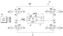
도 1은 본 발명의 실시 예에 따른 피에조 회로 및 피에조 구동 회로를 나타낸 도면이다.1 is a diagram illustrating a piezo circuit and a piezo driving circuit according to an embodiment of the present invention.
도 1에 도시된 피에조 구동 회로(20)에 연결된 피에조 회로(10)는 제1 인덕터(L), 제1 커패시터(CA), 및 저항(R)을 포함하는 직렬 공진 회로(11) 및 직렬 공진 회로(11)에 병렬 연결되어 있는 제2 커패시터(CB)를 포함한다.The
도 1에 도시된 피에조 회로(10)를 등가회로로 표현한 일 예에 지나지 않는다, 즉, 본 발명의 실시 예에 따른 피에조 구동 회로(20)는 도 1에 도시된 피에조 회로(10)에 한정되지 않으며, 다른 등가 회로로 구현된 피에조 회로에 적용될 수 있다.The
피에조 구동 회로(20)는 풀-브릿지 회로로 구현되고, 4 개의 스위치(S1-S4)를 포함한다. 4 개의 스위치(S1-S4)의 양 전극 사이에는 바디 다이오드(BD1-BD4) 및 기생 커패시터(C1-C4)가 병렬로 연결되어 있다. 피에조 구동 회로(20)는 직류전압(VDC)과 그라운드에 연결되어 있다.
직류전압(VDC)에 연결된 스위치를 상측 스위치라하고, 그라운드에 연결된 스위치를 하측 스위치라 한다. 예를 들어, 제1 및 제2 스위치(S1, S2)들은 상측 스위치이고, 제3 및 제4 스위치(S3, S4)들을 하측 스위치라 한다.A switch connected to the DC voltage VDC is referred to as an upper switch, and a switch connected to the ground is referred to as a lower switch. For example, the first and second switches S1 and S2 are upper switches, and the third and fourth switches S3 and S4 are called lower switches.
본 발명의 실시 예에 따른 제1 내지 제4 스위치(S1-S4)는 n 채널 타입의 MOSFET으로 구현되어 있다. 제1 내지 제4 스위치(S1-S4)의 제1 전극은 드레인 전극이고, 제2 전극은 소스 전극이며, 제어 전극은 게이트 전극이다. 다만, 본 발명의 실시 예에 따른 제1 내지 제4 스위치가 MOSFET에 한정되는 것은 아니고, MOSFET 대신 BJT 또는 IGBT로 구현될 수 있다.The first to fourth switches S1 to S4 according to the embodiment of the present invention are implemented as n-channel type MOSFETs. The first electrode of the first through fourth switches S1-S4 is a drain electrode, the second electrode is a source electrode, and the control electrode is a gate electrode. However, the first to fourth switches according to the embodiment of the present invention are not limited to the MOSFET, but may be implemented as a BJT or an IGBT instead of the MOSFET.
제1 스위치(S1)의 소스 전극과 제3 스위치(S3)의 드레인 전극은 접점(N1)에 연결되어 있고, 제2 스위치(S2)의 소스 전극과 제4 스위치(S4)의 드레인 전극의 접점(N2)에 연결되어 있다. 접점(N1) 및 접점(N2)는 피에조 구동 회로(20)의 출력단이고, 피에조 회로(10)는 접점(N1) 및 접점(N2) 사이에 연결되어 있다.The source electrode of the first switch S1 and the drain electrode of the third switch S3 are connected to the contact N1 and the contact of the source electrode of the second switch S2 and the drain electrode of the fourth switch S4 (N2). The contact point N1 and the contact point N2 are output ends of the
피에조 회로(10)에서, 제1 커패시터(CA), 제1 인덕터(L) 및 저항(R)은 접점(N1) 및 접점(N2) 사이에 직렬 연결되어 있다. 직렬 연결되어 있는 제1 커패시터(CA), 제1 인덕터(L) 및 저항(R)은 직렬 공진 회로(11)를 구성한다. 제2 커패시터(CB)는 접점(N1)과 접점(N2) 사이에 연결되어 있고, 직렬 공진 회로와 병렬 연결되어 있다. In the
전류(IM)는 직렬 공진 회로에 흐르는 전류이고, 전류(ICB)는 제2 커패시터(CB)에 흐르는 전류이며, 피에조 전류(IPIEZO)는 피에조 회로(10)에 공급되는 전류로서, 전류(IM)와 전류(ICB)의 합이다.The current IM is a current flowing in the series resonance circuit and the current ICB is a current flowing in the second capacitor CB and the piezo current IPIEZO is a current supplied to the
구체적으로, 제1 커패시터(CA)의 일단은 접점(N1)에 연결되어 있다. 제1 인덕터(L)의 일단은 제1 커패시터(CA)의 타단에 연결되어 있다. 저항(R)의 일단은 제1 인덕터(L)의 타단에 연결되어 있고, 저항(R)의 타단은 접점(N2)에 연결되어 있다.Specifically, one end of the first capacitor CA is connected to the contact N1. One end of the first inductor L is connected to the other end of the first capacitor CA. One end of the resistor R is connected to the other end of the first inductor L and the other end of the resistor R is connected to the contact N2.
제1 스위치(S1) 및 제2 스위치(S2)의 드레인 전극은 전압(VDC)에 연결되어 있고, 제3 스위치(S3) 및 제4 스위치(S4)의 소스 전극은 그라운드에 연결되어 있다.The drain electrodes of the first switch S1 and the second switch S2 are connected to the voltage VDC and the source electrodes of the third switch S3 and the fourth switch S4 are connected to the ground.
제1 스위치(S1)의 게이트 전극에는 제1 게이트 전압(VA)이 공급되고, 제2 스위치(S2)의 게이트 전극에는 제2 게이트 전압(VB)이 공급된다. 제3 스위치(S3)의 게이트 전극에는 제3 게이트 전압(VC)이 공급되고, 제4 스위치(S4)의 게이트 전극에는 제4 게이트 전압(VD)이 공급된다.The first gate voltage VA is supplied to the gate electrode of the first switch S1 and the second gate voltage VB is supplied to the gate electrode of the second switch S2. The third gate voltage VC is supplied to the gate electrode of the third switch S3 and the fourth gate voltage VD is supplied to the gate electrode of the fourth switch S4.
스위치 제어부(30)는 기준 정현파(sinewave)(SIN)와 반전 기준 정현파(RSIN)를 생성하고, 소정의 주파수를 가지는 램프 신호를 이용하여 제1 내지 제4 스위치(S1-S4)의 스위칭 동작을 제어하는 제1 내지 제4 게이트 전압(QA, QB, QC, QD)를 생성한다. 기준 정현파(SIN)는 정류 정현파를 따르고, 반전 기준 정현파는 기준 정현파(SIN)가 반전된 파형일 수 있다. 램프 신호는 톱니파(sawtooth wave) 또는 삼각파(triangle wave) 일 수 있다. 본 발명의 실시 예에서의 램프 신호는 톱니파로 설정한다.The
기준 정현파(SIN) 및 반전 기준 정현파(RSIN)의 주기는 피에조 전압(VPIEZO)의 주기를 제어하고, 램프 신호는 스위칭 주파수를 제어할 수 있다. 구체적으로, 스위치 제어부(30)는 피에조 전압(VPIEZO)의 주기를 제어하기 위해 입력 펄스(INP)를 생성하고, 입력 펄스(INP)의 반주기를 한 주기로 가지는 기준 정현파(SIN)와 반전 기준 정현파(RSIN)를 생성한다. 이 때, 기준 정현파(SIN)와 반전 기준 정현파(RSIN)는 소정의 기준 전압을 기준으로 서로 반전되어 있다. 톱니파(SAW)의 피크와 최저의 중간은 기준 전압이다. 톱니파(SAW)의 주파수는 제1 내지 제4 스위치의 스위칭 주파수를 결정한다.The period of the reference sinusoidal wave (SIN) and the inversion reference sinusoidal wave (RSIN) controls the period of the piezo voltage (VPIEZO), and the ramp signal can control the switching frequency. Specifically, the
이하, 도 2를 참조하여 본 발명의 실시 예에 따른 스위치 제어부(30)에 대해서 상세히 설명한다.Hereinafter, the
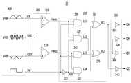
도 2는 본 발명의 실시 예에 따른 스위치 제어부를 나타낸 도면이다.2 is a diagram illustrating a switch control unit according to an embodiment of the present invention.
도 2에 도시된 바와 같이 스위치 제어부(30)는 PWM 비교부(100), 논리 연산부(200), 게이트 구동부(300), 및 신호 생성기(400)를 포함한다.2, the
신호 생성기(400)는 입력펄스(INP), 기준 정현파(SIN), 반전 기준 정현파(RSIN), 및 톱니파(SAW)를 생성한다. 신호 생성기(400)는 피에조 전압(VPIEZO)의 한 주기(CT0)와 동일한 주기를 가지는 입력펄스(INP)를 생성하고, 스위칭 주파수를 제어하는 톱니파(SAW)를 생성한다.The
신호 생성기(400)는 입력펄스(INP)의 반 주기를 한 주기(CT1)로 가지는 기준 정현파(SIN) 및 반파 기준 정현파(RSIN)를 생성한다. 신호 생성기(400)는 주기(CT1)의 반 기간(CT2) 동안 증가하는 디지털 신호를 아날로그 전압으로 변환하고, 나머지 반 기간(CT3) 동안 감소하는 디지털 신호를 아날로그 전압으로 변환하여 기준 정현파(SIN)를 생성할 수 있다.The
또한, 신호 생성기(400)는 주기(CT1)의 반 기간(CT2) 동안 감소하는 디지털 신호를 아날로그 전압으로 변환하고, 나머지 반 기간(CT3) 동안 증가하는 디지털 신호를 아날로그 전압으로 변환하여 반전 기준 정현파(RSIN)를 생성할 수 있다.The
PWM 비교부(100)는 기준 정현파(SIN)와 톱니파(SAW)를 비교한 제1 PWM 출력(PWM1) 및 반전 기준 정현파(RSIN)와 톱니파(SAW)를 비교한 제2 PWM 출력(PWM2)을 생성한다. PWM 비교부(100)는 제1 PWM 비교기(110) 및 제2 PWM 비교기(120)를 포함한다.The
제1 PWM 비교기(110)는 비반전단자(+)에 입력되는 기준 정현파(SIN)와 반전단자(-)에 입력되는 톱니파(SAW)를 비교한 결과에 따라 제1 PWM 출력(PWM1)을 생성한다.The
제2 PWM 비교기(120)는 비반전단자(+)에 입력되는 반전 기준 정현파(RSIN)와 반전단자(-)에 입력되는 톱니파(SAW)를 비교한 결과에 따라 제2 PWM 출력(PWM2)을 생성한다. 제1 및 제2 PWM 비교기(110, 120)는 비반전단자(+)의 입력이 반전 단자(-)의 입력 이상일 때 하이 레벨을 출력하고, 그 반대의 경우 로우 레벨을 출력한다.The
논리 연산부(200)는 입력 펄스(INP), 제1 PWM 출력(PWM1), 및 제2 PWM 출력(PWM2)을 이용하여 게이트 구동부(300)를 제어하기 위한 제1 게이트 제어 신호(VC1) 및 제2 게이트 제어 신호(VC2)를 생성한다.The
논리 연산부(200)는 인버터(210), 제1 내지 제4 AND 게이트(220-250), 및 제1 및 제2 OR 게이트(260, 270)를 포함한다.The
인버터(210)는 입력 펄스(INP)를 반전시킨다. 인버터(210)의 출력을 반전 입력 펄스(INP)라 한다.The
제1 AND 게이트(220)는 제1 PWM 출력(PWM1) 및 입력 펄스(INP)를 논리 곱 연산한다. 즉, 제1 PWM 출력(PWM1) 및 입력 펄스(INP) 모두가 논리 레벨 1에 대응하는 하이 레벨일 때 논리 레벨 1의 하이 레벨 출력을 생성한다. 제1 AND 게이트(220)의 출력을 제1 논리 출력(LS1)이라 한다.The first AND
제2 AND 게이트(230)는 제1 PWM 출력(PWM1) 및 반전 입력 펄스(INP)를 논리 곱 연산한다. 즉, 제1 PWM 출력(PWM1) 및 반전 입력 펄스(INP) 모두가 논리 레벨 1에 대응하는 하이 레벨일 때 논리 레벨 1의 하이 레벨 출력을 생성한다. 제2 AND 게이트(230)의 출력을 제2 논리 출력(LS2)이라 한다.The second AND
제3 AND 게이트(240)는 제2 PWM 출력(PWM2) 및 입력 펄스(INP)를 논리 곱 연산한다. 즉, 제2 PWM 출력(PWM2) 및 입력 펄스(INP) 모두가 논리 레벨 1에 대응하는 하이 레벨일 때 논리 레벨 1의 하이 레벨 출력을 생성한다. 제3 AND 게이트(240)의 출력을 제3 논리 출력(LS3)이라 한다.The third AND
제4 AND 게이트(250)는 제2 PWM 출력(PWM2) 및 반전 입력 펄스(INP)를 논리 곱 연산한다. 즉, 제2 PWM 출력(PWM2) 및 반전 입력 펄스(INP) 모두가 논리 레벨 1에 대응하는 하이 레벨일 때 논리 레벨 1의 하이 레벨 출력을 생성한다. 제4 AND 게이트(250)의 출력을 제4 논리 출력(LS4)이라 한다.The fourth AND
제1 OR 게이트(260)는 제1 논리 출력(LS1) 및 제4 논리 출력(LS4)을 논리 합 연산하여 제1 스위치 및 제3 스위치(S1, S3)의 스위칭 동작을 제어하는 제1 게이트 제어 신호(VC1)를 생성한다. 즉, 제1 및 제4 논리 출력(LS1, LS4) 중 적어도 하나가 논리 레벨 1의 하이 레벨이면 제1 게이트 제어 신호(VC1)는 하이 레벨이다.The first OR
제2 OR 게이트(270)는 제2 논리 출력(LS2) 및 제3 논리 출력(LS3)을 논리 합 연산하여 제2 스위치 및 제4 스위치(S2, S4)의 스위칭 동작을 제어하는 제2 게이트 제어 신호(VC2)를 생성한다. 즉, 제2 및 제3 논리 출력(LS2, LS3) 중 적어도 하나가 논리 레벨 1의 하이 레벨이면 제2 게이트 제어 신호(VC2)는 하이 레벨이다.The second OR
게이트 구동부(300)는 제1 게이트 제어 신호(VC1)에 따라 제1 게이트 전압(QA) 및 제3 게이트 전압(QC)을 생성하고, 제2 게이트 제어 신호(VC2)에 따라 제2 게이트 전압(QB) 및 제4 게이트 전압(QD)을 생성한다. 이 때, 제1 게이트 전압(QA)과 제3 게이트 전압(QC)은 서로 반전 위상이고, 제2 게이트 전압(QB)과 제4 게이트 전압(QD)은 서로 반전 위상일 수 있다.The
게이트 구동부(300)는 제1 및 제2 인버터(310, 320), 및 제1 및 제2 버퍼(330, 340)를 포함한다.The
제1 인버터(310)는 제1 게이트 제어 신호(VC1)를 반전시켜 제1 게이트 전압(QA)를 생성하고, 제2 인버터(320)는 제2 게이트 제어 신호(VC2)를 반전시켜 제2 게이트 전압(QB)를 생성한다.The
제1 버퍼(330)는 제2 게이트 제어 신호(VC1)에 따라 출력 레벨을 시프트하여 제4 게이트 전압(QD)을 생성하고, 제2 버퍼(340)는 제1 게이트 제어 신호(VC1)에 따라 출력 레벨을 시프트하여 제3 게이트 전압(QC)을 생성한다. 출력 레벨은 제3 및 제4 스위치(S3, S4)를 온 또는 오프시키기에 충분한 레벨을 의미한다.The
이와 같이 구성된 스위치 제어부(30)의 동작을 도 3 및 4를 참조하여 설명한다.The operation of the
도 3은 본 발명의 실시 예에 따른 입력 펄스, 기준 정현파, 반전 기준 정현파, 톱니파, 제1 PWM 출력, 제2 PWM 출력 및 피에조 전압을 나타낸 파형도이다.3 is a waveform diagram showing an input pulse, a reference sinusoidal wave, an inverted reference sinusoidal wave, a sawtooth wave, a first PWM output, a second PWM output, and a piezoelectric voltage according to an embodiment of the present invention.
도 4는 본 발명의 실시 예에 따른 제1 PWM 출력, 제2 PWM 출력, 및 제1 내지 제4 게이트 전압을 나타낸 파형도이다.4 is a waveform diagram showing a first PWM output, a second PWM output, and first through fourth gate voltages according to an embodiment of the present invention.
피에조 전압(VPIEZO)의 주기(CT0')는 입력 펄스(INP)의 한 주기(CT0)와 동일하게 제어된다. 주기(CT0)의 반에 해당하는 주기(CT1) 동안 기준 정현파(SIN)는 증가 후 감소하고, 반전 기준 정현파(RSIN)는 감소 후 증가한다. 도 3에서 도시된 피에조 전압(VPIEZO)과 입력 펄스(INP)의 위상 차는 일 예시로서 본 발명이 이에 한정되는 것은 아니다.The period CT0 'of the piezo voltage VPIEZO is controlled to be the same as one period CT0 of the input pulse INP. During the period CT1 corresponding to half of the period CT0, the reference sine wave SIN decreases and then decreases, and the inverse reference sine wave RSIN decreases and then increases. The phase difference between the piezo voltage VPIEZO and the input pulse INP shown in FIG. 3 is an example, and the present invention is not limited thereto.
기준 정현파(SIN) 및 반전 기준 정현파(RSIN)는 디지털 신호를 아날로그 전압으로 변환하여 생성될 수 있으므로, 도 3에서는 계단식으로 변하도록 도시되어 있다. 그러나 이는 이해를 돕기위해 계단식으로 도시한 것일 뿐이다.The reference sinusoidal wave (SIN) and the inversion reference sinusoidal wave (RSIN) can be generated by converting a digital signal into an analog voltage, and thus are shown to change stepwise in Fig. However, this is only a step-by-step illustration to aid understanding.
실제 디지털 신호의 주파수를 조절하여 도 3에서 톱니파(SAW)에 겹쳐 도시한 것과 같이 매끄로운 곡선과 유사하도록 생성된다. 이하, 톱니파(SAW)와 PWM 비교부(100)에서 비교되는 기준 정현파(SIN) 및 반전 기준 정현파(RSIN)는 곡선으로 설정한다.The frequency of the actual digital signal is adjusted so as to be similar to the smooth curve as shown in Fig. 3, superimposed on the sawtooth wave (SAW). Hereinafter, the reference sinusoidal wave SIN and the inverse reference sinusoidal wave RSIN, which are compared by the sawtooth wave (SAW) and the
기준 정현파(SIN)와 반전 기준 정현파(RSIN)는 기준 전압(VREF)을 기준으로 서로 반전 위상이 되도록 생성되고, 톱티파(SAW)의 피크와 최저의 중간 전압은 기준 전압(VREF)이다.The reference sinusoidal wave SIN and the inverted reference sinusoidal wave RSIN are generated so as to be in opposite phase to each other with reference to the reference voltage VREF and the peak of the top wave SAW and the lowest intermediate voltage are the reference voltage VREF.
제1 PWM 출력(PWM1)은 톱니파(SAW)가 기준 정현파(SIN)보다 작아지는 시점(예를 들어, T0)에 하이 레벨로 상승하고, 톱니파(SAW)가 기준 정현파(SIN)이상이 되는 시점(예를 들어, T1)에 로우 레벨로 감소한다. 따라서 기준 정현파(SIN)가 증가하는 기간(CT2) 동안 제1 PWM 출력(PWM1)의 펄스 폭은 증가하고, 기준 정현파(SIN)가 감소하는 기간(CT3) 동안 제1 PWM 출력(PWM1)의 펄스 폭은 감소한다.The first PWM output PWM1 rises to a high level at a time point (for example, T0) at which the sawtooth wave SAW becomes smaller than the reference sinusoidal wave SIN and the sawtooth wave SAW reaches the reference sinusoidal wave SIN (E. G., T1). ≪ / RTI > The pulse width of the first PWM output PWM1 is increased during the period CT2 during which the reference sinusoidal wave SIN increases and the pulse width of the pulse of the first PWM output PWM1 during the period CT3 during which the reference sinusoidal wave SIN decreases, The width decreases.
제2 PWM 출력(PWM2)은 톱니파(SAW)가 반전 기준 정현파(RSIN)보다 작아지는 시점(예를 들어, T0)에 하이 레벨로 상승하고, 톱니파(SAW)가 반전 기준 정현파(RSIN)이상이 되는 시점(예를 들어, T2)에 로우 레벨로 감소한다. 따라서 반전 기준 정현파(RSIN)가 감소하는는 기간(CT2) 동안 제2 PWM 출력(PWM2)의 펄스 폭은 감소하고, 반전 기준 정현파(RSIN)가 증가하는 기간(CT3) 동안 제2 PWM 출력(PWM2)의 펄스 폭은 증가한다.The second PWM output PWM2 rises to a high level at a time point (for example, T0) when the sawtooth wave SAW becomes smaller than the inversion reference sinusoidal wave RSIN and the sawtooth wave SAW rises above the inversion reference sinusoidal wave RSIN (E. G., T2). ≪ / RTI > The pulse width of the second PWM output PWM2 decreases during the period CT2 during which the inversion reference sine wave RSIN decreases and the second PWM output PWM2 during the period CT3 during which the inversion reference sinusoidal wave RSIN increases, Pulse width increases.
입력 펄스(INP)가 하이 레벨인 기간(CT1) 동안, 반전 입력 펄스(INP)가 입력되는 제2 및 제4 AND 게이트(230, 250)의 제2 및 제4 논리 출력(LS2, LS4)은 로우 레벨이다. 따라서 제1 OR 게이트(260)의 출력은 제1 논리 출력(LS1)에 따르고, 제2 OR 게이트(270)의 출력은 제3 논리 출력(LS3)에 따른다.The second and fourth logic outputs LS2 and LS4 of the second and fourth AND
제1 논리 출력(LS1)은 제1 PWM 출력(PWM1)에 따르므로, 제1 게이트 제어 신호(VC1)은 제1 PWM 출력(PWM1)에 따른다. 도 4에 도시된 바와 같이 기간(CT1) 동안, 제1 게이트 전압(QA)은 제1 게이트 제어 신호(VC1)의 반전 출력이므로, 제1 PWM 출력(PWM1)의 반전 위상(PWM1_B)에 따르고, 제3 게이트 전압(QC)은 제1 게이트 제어 신호(VC1)에 따르므로, 제1 PWM 출력(PWM1)의 위상에 따른다.Since the first logic output LS1 follows the first PWM output PWM1, the first gate control signal VC1 follows the first PWM output PWM1. 4, the first gate voltage QA is an inverted output of the first gate control signal VC1 during the period CT1, and therefore follows the inverted phase PWM1_B of the first PWM output PWM1, Since the third gate voltage QC follows the first gate control signal VC1, it follows the phase of the first PWM output PWM1.
제3 논리 출력(LS3)은 제2 PWM 출력(PWM2)에 따르므로, 제2 게이트 제어 신호(VC2)는 제2 PWM 출력(PWM2)에 따른다. 도 4에 도시된 바와 같이 기간(CT1) 동안, 제2 게이트 전압(QB)은 제2 게이트 제어 신호(VC2)의 반전 출력이므로, 제2 PWM 출력(PWM2)의 반전 위상(PWM2_B)에 따르고, 제4 게이트 전압(QD)은 제2 게이트 제어 신호(VC2)에 따르므로, 제2 PWM 출력(PWM2)의 위상에 따른다.Since the third logic output LS3 follows the second PWM output PWM2, the second gate control signal VC2 follows the second PWM output PWM2. The second gate voltage QB is an inverted output of the second gate control signal VC2 during the period CT1 as shown in Fig. 4 and therefore follows the inverted phase PWM2_B of the second PWM output PWM2, The fourth gate voltage QD depends on the second gate control signal VC2 and therefore follows the phase of the second PWM output PWM2.
입력 펄스(INP)가 로우 레벨인 기간(CT4) 동안, 입력 펄스(INP)가 입력되는 제1 및 제3 AND 게이트(220, 240)의 제1 및 제3 논리 출력(LS1, LS3)은 로우 레벨이다. 따라서 제1 OR 게이트(260)의 출력은 제4 논리 출력(LS4)에 따르고, 제2 OR 게이트(270)의 출력은 제2 논리 출력(LS2)에 따른다.The first and third logic outputs LS1 and LS3 of the first and third AND
제4 논리 출력(LS4)은 제2 PWM 출력(PWM2)에 따르므로, 제1 게이트 제어 신호(VC1)은 제2 PWM 출력(PWM2)에 따른다. 도 4에 도시된 바와 같이 기간(CT4) 동안, 제1 게이트 전압(QA)은 제1 게이트 제어 신호(VC1)의 반전 출력이므로, 제2 PWM 출력(PWM2)의 반전 위상(PWM1_B)에 따르고, 제3 게이트 전압(QC)은 제1 게이트 제어 신호(VC1)에 따르므로, 제2 PWM 출력(PWM2)의 위상에 따른다.Since the fourth logic output LS4 follows the second PWM output PWM2, the first gate control signal VC1 follows the second PWM output PWM2. Since the first gate voltage QA is the inverted output of the first gate control signal VC1 during the period CT4 as shown in Fig. 4, it follows the inverted phase PWM1_B of the second PWM output PWM2, Since the third gate voltage QC follows the first gate control signal VC1, it follows the phase of the second PWM output PWM2.
제2 논리 출력(LS2)은 제1 PWM 출력(PWM1)에 따르므로, 제2 게이트 제어 신호(VC2)는 제1 PWM 출력(PWM1)에 따른다. 도 4에 도시된 바와 같이 기간(CT4) 동안, 제2 게이트 전압(QB)은 제2 게이트 제어 신호(VC2)의 반전 출력이므로, 제1 PWM 출력(PWM1)의 반전 위상(PWM1_B)에 따르고, 제4 게이트 전압(QD)은 제2 게이트 제어 신호(VC2)에 따르므로, 제1 PWM 출력(PWM1)의 위상에 따른다.Since the second logic output LS2 follows the first PWM output PWM1, the second gate control signal VC2 follows the first PWM output PWM1. The second gate voltage QB is an inverted output of the second gate control signal VC2 during the period CT4 as shown in Fig. 4, so that it follows the inverted phase PWM1_B of the first PWM output PWM1, The fourth gate voltage QD depends on the second gate control signal VC2 and therefore follows the phase of the first PWM output PWM1.
이와 같이, 입력 펄스(INP)가 하이 레벨인 기간 동안, 제1 스위치(S1)는 제1 PWM 출력의 반전(PWM1_B)에 따라 제어되고, 제3 스위치(S3)는 제1 PWM 출력(PWM1)에 따라 제어되며, 제2 스위치(S2)는 제2 PWM 출력의 반전(PWM2_B)에 따라 제어되고, 제4 스위치(S4)는 제2 PWM 출력(PWM2)에 따라 제어된다.The first switch S1 is controlled according to the inversion PWM1_B of the first PWM output and the third switch S3 is controlled according to the first PWM output PWM1 during the period in which the input pulse INP is at the high level, The second switch S2 is controlled according to the inversion PWM2_B of the second PWM output and the fourth switch S4 is controlled according to the second PWM output PWM2.
입력 펄스(INP)가 로우 레벨인 기간 동안, 제1 스위치(S1)는 제2 PWM 출력의 반전(PWM2_B)에 따라 제어되고, 제3 스위치(S3)는 제2 PWM 출력(PWM2)에 따라 제어되며, 제2 스위치(S2)는 제1 PWM 출력의 반전(PWM1_B)에 따라 제어되고, 제4 스위치(S4)는 제1 PWM 출력(PWM1)에 따라 제어된다.The first switch S1 is controlled according to the inversion PWM2_B of the second PWM output and the third switch S3 is controlled according to the second PWM output PWM2 while the input pulse INP is at the low level, And the second switch S2 is controlled according to the inversion PWM1_B of the first PWM output and the fourth switch S4 is controlled according to the first PWM output PWM1.
이와 같이, 피에조 구동 회로(20)의 풀-브릿지 회로의 스위치들을 제어하여 피에조 전압(VPIEZO)이 정현파를 따르도록 제어한다. 피에조 전압(VPIEZO)이 정현파를 따를 때의 스위칭 동작시 발생하는 피크 전류는 피에조 전압(VPIEZO)이 구형파를 따를 때에 비해 감소한다.Thus, the switches of the full-bridge circuit of the
본 발명의 실시 예에서는 제1 게이트 제어 신호(VC1) 및 제2 게이트 제어 신호(VC2)를 반전시켜 제1 게이트 전압(QA) 및 제2 게이트 전압(QB)을 생성하였으나, 본 발명이 이에 한정되는 것은 아니다,Although the first and second gate control signals VC1 and VC2 are inverted to generate the first gate voltage QA and the second gate voltage QB in the exemplary embodiment of the present invention, Not so,
예를 들어, 제1 게이트 제어 신호(VC1)에 따라 제1 게이트 전압(QA)을 생성하고, 제1 게이트 제어 신호(VC1)를 반전시켜 제3 게이트 전압을 생성하며, 제2 게이트 제어 신호(VC2)에 따라 제2 게이트 전압(QB)을 생성하고, 제2 게이트 제어 신호(VC2)를 반전시켜 제4 게이트 전압(QD)을 생성할 수 있다. 그러면, 도 3에 도시된 피에조 전압(VPIEZO)이 반전된 위상의 피에조 전압이 발생한다.For example, a first gate voltage (QA) is generated in accordance with a first gate control signal (VC1), a first gate control signal (VC1) is inverted to generate a third gate voltage, VC2 to generate the second gate voltage QB and invert the second gate control signal VC2 to generate the fourth gate voltage QD. Then, the piezo-electric voltage of the phase in which the piezo-electric voltage VPIEZO shown in Fig. 3 is inverted is generated.
앞서 설명한 본 발명의 실시 예에서는 톱니파를 사용하여 제1 PWM 출력 및 제2 PWM 출력을 생성하였으나, 본 발명이 이에 한정되는 것은 아니다. 톱니파 대신 삼각파를 사용할 수도 있다.In the above-described embodiments of the present invention, the sawtooth wave is used to generate the first PWM output and the second PWM output, but the present invention is not limited thereto. Triangular waves can be used instead of sawtooth.
도 5는 본 발명의 다른 실시 예에 따른 입력 펄스, 기준 정현파, 반전 기준 정현파, 삼각파, 제1 PWM 출력, 제2 PWM 출력 및 피에조 전압을 나타낸 파형도이다.FIG. 5 is a waveform diagram illustrating an input pulse, a reference sinusoidal wave, an inverted reference sinusoidal wave, a triangular wave, a first PWM output, a second PWM output, and a piezo voltage according to another embodiment of the present invention.
도 5에 도시된 바와 같이, 제1 PWM 출력(PWM1')은 기준 정현파(SIN)가 삼각파(TRS) 이상일 때 하이 레벨이고, 반대의 경우 로우 레벨인 펄스 파형이고, 제2 PWM 출력(PWM2')은 반전 기준 정현파(RSIN)가 삼각파(TRS) 이상일 때 하이 레벨이고, 반대의 경우 로우 레벨인 펄스 파형이다.5, the first PWM output PWM1 'is a pulse waveform having a high level when the reference sine wave SIN is equal to or higher than the triangular wave TRS and a low level when the reference sine wave SIN is equal to or higher than the triangular wave TRS. Is a pulse waveform that is high level when the inversion reference sinusoidal wave RSIN is greater than or equal to the triangular wave TRS and is low in the opposite case.
도 5에 도시된 바와 같이, 삼각파(TRS)를 이용하는 경우에도, 톱니파(SAW)에서 생성된 제1 및 제2 PWM 출력(PWM1, PWM2)과 유사하다. 본 발명의 다른 실시 예에 따른 스위치 제어부는 제1 및 제2 PWM 출력(PWM1', PWM2')을 이용하여 제1 내지 제4 게이트 전압(QA, QB, QC, QD)을 생성할 수 있다. 스위치 제어부의 구성 및 동작은 앞서 도 2를 참조로 한 설명과 유사한 바, 상세한 설명은 생략한다.As shown in Fig. 5, even when the triangular wave TRS is used, the first and second PWM outputs PWM1 and PWM2 generated by the sawtooth wave SAW are similar. The switch controller according to another embodiment of the present invention may generate the first to fourth gate voltages QA, QB, QC and QD using the first and second PWM outputs PWM1 'and PWM2'. The configuration and operation of the switch control unit are similar to those described above with reference to FIG. 2, and a detailed description thereof will be omitted.
본 발명의 실시 예들에 따른 피에조 구동 회로는 피크 전류를 감소시켜 종래 피에조 구동 회로에 비해 입력 전력을 감소시킬 수 있는 효과도 제공한다. 구체적으로, 피에조 회로의 기계적 에너지 예를 들어, 진동을 결정하는 전압은 커패시터(CA)의 양단 전압이다. 종래 피에조 회로에서 커패시터(CA)의 양단 전압을 필요한 만큼 얻기 위해 필요한 입력 전력에 비해 본 발명의 실시 예에 따른 입력 전력이 더 작다. 따라서 종래 피에조 회로와 비교해 동일한 기계적 에너지를 얻기 위해 필요한 전기 에너지가 적다.The piezo driving circuit according to the embodiments of the present invention also reduces the peak current, thereby reducing the input power as compared with the conventional piezo driving circuit. Specifically, the mechanical energy of the piezo circuit, for example, the voltage for determining the vibration, is the voltage across the capacitor CA. The input power according to the embodiment of the present invention is smaller than the input power required to obtain the voltage across the capacitor CA as required in the conventional piezo circuit. Therefore, the electric energy required to obtain the same mechanical energy as that of the conventional piezo circuit is small.
이상에서 본 발명의 실시예에 대하여 상세하게 설명하였지만 본 발명의 권리범위는 이에 한정되는 것은 아니고 다음의 청구범위에서 정의하고 있는 본 발명의 기본 개념을 이용한 당업자의 여러 변형 및 개량 형태 또한 본 발명의 권리범위에 속하는 것이다.While the present invention has been particularly shown and described with reference to exemplary embodiments thereof, it is to be understood that the invention is not limited to the disclosed exemplary embodiments, It belongs to the scope of right.
피에조 회로(10), 인덕터(L), 제1 커패시터(CA), 제2 커패시터(CB)
저항(R), 피에조 구동 회로(20), 바디 다이오드(BD1-BD4)
기생 커패시터(C1-C4), 제1 스위치 내지 제4 스위치(S1-S4)
직렬 공진 회로(11), 스위치 제어부(30), PWM 비교부(100)
논리 연산부(200), 게이트 구동부(300), 신호 생성기(400)
제1 PWM 비교기(110), 제2 PWM 비교기(120), 인버터(210)
제1 내지 제4 AND 게이트(220-250), 제1 및 제2 OR 게이트(260, 270)
제1 및 제2 인버터(310, 320), 제1 및 제2 버퍼(330, 340)
The
The resistor R, the
Parasitic capacitors C1 to C4, first to fourth switches S1 to S4,
A
A
The
First to fourth AND gates 220-250, first and second OR
The first and
Claims (20)
Translated fromKorean스위칭 주파수를 제어하는 램프 신호와 피에조 전압의 주기를 제어하는 기준 정현파를 비교한 결과에 따라 제1 PWM 출력을 생성하고, 상기 램프 신호와 상기 기준 정현파가 반전된 반전 기준 정현파를 비교한 결과에 따라 제2 PWM 출력을 생성하며,
상기 기준 정현파 및 상기 반전 기준 정현파의 제1 주기 동안 상기 제1 PWM 출력에 따라 상기 제1 및 제3 스위치의 스위칭 동작을 제어하고, 상기 제2 PWM 출력에 따라 상기 제2 및 제4 스위치의 스위칭 동작을 제어하고,
다음 제2 주기 동안 상기 제2 PWM 출력에 따라 상기 제1 및 제3 스위치의 스위칭 동작을 제어하고, 상기 제1 PWM 출력에 따라 상기 제2 및 제4 스위치의 스위칭 동작을 제어하는 스위치 제어부를 포함하는 피에조 구동 회로.A full-bridge circuit including first and third switches connected to one end of the piezo circuit, second and fourth switches connected to the other end of the piezo circuit,
A first PWM output is generated according to a result of comparing a ramp signal for controlling a switching frequency and a reference sinusoidal wave for controlling a period of a piezoelectric voltage, and according to a result of comparing the ramp signal and an inverted reference sine wave inverted from the reference sinusoidal wave Generates a second PWM output,
Controls the switching operation of the first and third switches according to the first PWM output during a first period of the reference sine wave and the inverted reference sine wave, and controls switching of the second and fourth switches Control the operation,
And a switch control unit for controlling the switching operation of the first and third switches according to the second PWM output during the second period and controlling the switching operation of the second and fourth switches according to the first PWM output .
상기 제1 스위치는, 직류 전압과 상기 피에조 회로의 일단 사이에 연결되어있고, 상기 제2 스위치는 상기 직류 전압과 상기 피에조 회로의 타단 사이에 연결되어 있으며, 상기 제3 스위치는 상기 피에조 회로의 일단과 그라운드 사이에 연결되어 있으며, 상기 제4 스위치는 상기 피에조 회로의 타단과 그라운드 사이에 연결되어 있는 피에조 구동 회로.The method according to claim 1,
Wherein the first switch is connected between a DC voltage and one end of the piezo circuit, the second switch is connected between the DC voltage and the other end of the piezo circuit, And the fourth switch is connected between the other terminal of the piezo-electric circuit and the ground.
상기 스위치 제어부는,
소정 주기의 입력 펄스를 생성하고, 상기 입력 펄스의 주기에 대응하는 주기를 가지는 상기 기준 정현파 및 상기 반전 기준 정현파를 생성하는 신호 생성기를 포함하는 피에조 구동 회로.The method according to claim 1,
The switch control unit,
And a signal generator for generating an input pulse of a predetermined period and generating the reference sine wave and the inversion reference sine wave having a period corresponding to the period of the input pulse.
상기 기준 정현파 및 상기 반전 기준 정현파의 한 주기는 상기 입력 펄스 주기의 반인 피에조 구동 회로.The method of claim 3,
Wherein one period of the reference sinusoidal wave and the inverted reference sinusoidal wave is half the input pulse period.
상기 스위치 제어부는,
상기 램프 신호 및 상기 기준 정현파를 비교하여 상기 제1 PWM 출력을 생성하고, 상기 램프 신호 및 상기 반전 기준 정현파를 비교하여 상기 제2 PWM 출력을 생성하는 PWM 비교부, 및
상기 입력 펄스가 제1 레벨일 때 상기 제1 PWM 출력에 따라 제1 게이트 제어 신호를 생성하고, 상기 제2 PWM 출력에 따라 제2 게이트 제어 신호를 생성하며, 상기 입력 펄스가 제2 레벨일 때 상기 제1 PWM 출력에 따라 제2 게이트 제어 신호를 생성하고, 상기 제1 PWM 출력에 따라 제1 게이트 제어 신호를 생성하는 논리 연산부를 더 포함하고,
상기 스위치 제어부는,
상기 제1 게이트 제어 신호를 이용하여 상기 제1 스위치의 제1 게이트 전압 및 상기 제3 스위치의 제3 게이트 전압을 생성하고, 상기 제2 게이트 제어 신호를 이용하여 상기 제2 스위치의 제2 게이트 전압 및 상기 제4 스위치의 제4 게이트 전압을 생성하는 피에조 구동 회로.The method of claim 3,
The switch control unit,
A PWM comparator for comparing the ramp signal and the reference sinusoidal wave to generate the first PWM output and comparing the ramp signal and the inverted reference sinusoidal wave to generate the second PWM output;
Generates a first gate control signal in accordance with the first PWM output when the input pulse is at a first level and generates a second gate control signal in accordance with the second PWM output, Further comprising a logic operation unit for generating a second gate control signal in accordance with the first PWM output and generating a first gate control signal in accordance with the first PWM output,
The switch control unit,
Generating a first gate voltage of the first switch and a third gate voltage of the third switch using the first gate control signal and using the second gate control signal to generate a second gate voltage of the second switch And a fourth gate voltage of the fourth switch.
상기 스위치 제어부는,
상기 제1 게이트 제어 신호를 반전하여 상기 제1 스위치의 제1 게이트 전압을 생성하고, 상기 제1 게이트 제어 신호에 따라 제3 스위치의 제3 게이트 전압을 생성하며, 상기 제2 게이트 제어 신호를 반전하여 상기 제2 스위치의 제2 게이트 전압을 생성하고, 상기 제2 게이트 제어 신호에 따라 상기 제4 스위치의 제4 게이트 전압을 생성하는 게이트 구동부를 더 포함하는 피에조 구동 회로.6. The method of claim 5,
The switch control unit,
Inverts the first gate control signal to generate a first gate voltage of the first switch, generates a third gate voltage of the third switch in accordance with the first gate control signal, inverts the second gate control signal, Further comprising a gate driver for generating a second gate voltage of the second switch and generating a fourth gate voltage of the fourth switch in accordance with the second gate control signal.
상기 PWM 비교부는,
상기 램프 신호가 입력되는 반전단자 및 상기 기준 정현파가 입력되는 비반전단자를 포함하고, 상기 비반전단자의 입력이 상기 반전단자의 입력 이상일 때 하이 레벨의 제1 PWM 출력을 생성하고, 상기 비반전단자의 입력이 상기 반전단자의 입력보다 작을 때 로우 레벨의 제1 PWM 출력을 생성하는 제1 PWM 비교기, 및
상기 램프 신호가 입력되는 반전단자 및 상기 반전 기준 정현파가 입력되는 비반전단자를 포함하고, 상기 비반전단자의 입력이 상기 반전단자의 입력 이상일 때 하이 레벨의 제2 PWM 출력을 생성하고, 상기 비반전단자의 입력이 상기 반전단자의 입력보다 작을 때 로우 레벨의 제2 PWM 출력을 생성하는 제2 PWM 비교기를 포함하는 피에조 구동 회로.6. The method of claim 5,
Wherein the PWM comparator comprises:
A non-inverting terminal to which the ramp signal is input and a non-inverting terminal to which the reference sine wave is input, and generates a high-level first PWM output when the input of the non-inverting terminal is an input error of the inverting terminal, A first PWM comparator that generates a low-level first PWM output when the input of the terminal is less than the input of the inverting terminal, and
And a non-inverting terminal to which the inverting reference sine wave is inputted, and generates a second PWM output of a high level when the input of the non-inverting terminal is an input of the inverting terminal or more, And a second PWM comparator that generates a low-level second PWM output when the input of the inverting terminal is smaller than the input of the inverting terminal.
상기 논리 연산부는,
상기 제1 PWM 출력 및 상기 입력 펄스를 논리 곱 연산하는 제1 AND 게이트,
상기 제1 PWM 출력 및 상기 반전 입력 펄스를 논리 곱 연산하는 제2 AND 게이트,
상기 제2 PWM 출력 및 상기 입력 펄스를 논리 곱 연산하는 제3 AND 게이트,
상기 제2 PWM 출력 및 상기 반전 입력 펄스를 논리 곱 연산하는 제4 AND 게이트,
상기 제1 AND 게이트의 출력 및 상기 제4 AND 게이트의 출력을 논리 합 연산하여 상기 제1 게이트 제어 신호를 생성하는 제1 OR 게이트, 및
상기 제2 AND 게이트의 출력 및 상기 제3 AND 게이트의 출력을 논리 합 연산하여 상기 제2 게이트 제어 신호를 생성하는 제2 OR 게이트를 포함하는 피에조 구동 회로.6. The method of claim 5,
Wherein the logical operation unit comprises:
A first AND gate for ANDing the first PWM output and the input pulse,
A second AND gate for ANDing the first PWM output and the inverting input pulse,
A third AND gate for ANDing the second PWM output and the input pulse,
A fourth AND gate for ANDing the second PWM output and the inverting input pulse,
A first OR gate for performing an OR operation on an output of the first AND gate and an output of the fourth AND gate to generate the first gate control signal;
And a second OR gate for performing a logical sum operation on the output of the second AND gate and the output of the third AND gate to generate the second gate control signal.
상기 논리 연산부는,
상기 입력 펄스를 반전시켜 상기 반전 입력 펄스를 생성하는 인버터를 더 포함하는 피에조 구동 회로.9. The method of claim 8,
Wherein the logical operation unit comprises:
And an inverter for inverting the input pulse to generate the inverted input pulse.
상기 램프 신호는 톱니파 또는 삼각파인 피에조 구동 회로.The method according to claim 1,
Wherein the ramp signal is a sawtooth wave or a triangle wave.
스위칭 주파수를 제어하는 램프 신호와 피에조 전압의 주기를 제어하는 기준 정현파를 비교한 결과에 따라 제1 PWM 출력을 생성하는 단계,
상기 램프 신호와 상기 기준 정현파가 반전된 반전 기준 정현파를 비교한 결과에 따라 제2 PWM 출력을 생성하는 단계,
상기 기준 정현파 및 상기 반전 기준 정현파의 제1 주기 동안 상기 제1 PWM 출력에 따라 상기 제1 및 제3 스위치의 스위칭 동작을 제어하는 단계,
상기 제1 주기 동안 상기 제2 PWM 출력에 따라 상기 제2 및 제4 스위치의 스위칭 동작을 제어하는 단계,
다음 제2 주기 동안 상기 제2 PWM 출력에 따라 상기 제1 및 제3 스위치의 스위칭 동작을 제어하는 단계, 및
상기 제2 주기 동안 상기 제1 PWM 출력에 따라 상기 제2 및 제4 스위치의 스위칭 동작을 제어하는 단계를 포함하는 피에조 구동 회로의 구동 방법.A driving method of a piezo driving circuit including first and third switches connected to one end of a piezo circuit, and second and fourth switches connected to the other end of the piezo circuit,
Generating a first PWM output according to a result of comparing a ramp signal for controlling a switching frequency and a reference sine wave for controlling a period of a piezo voltage,
Generating a second PWM output according to a result of comparing the ramp signal with an inverted reference sine wave having the reference sine wave inverted,
Controlling a switching operation of the first and third switches according to the first PWM output during a first period of the reference sinusoidal wave and the inverted reference sinusoidal wave,
Controlling a switching operation of the second and fourth switches according to the second PWM output during the first period,
Controlling a switching operation of said first and third switches in accordance with said second PWM output for a second second period, and
And controlling the switching operation of the second and fourth switches according to the first PWM output during the second period.
소정 주기의 입력 펄스를 생성하고, 상기 입력 펄스의 주기에 대응하는 주기를 가지는 상기 기준 정현파 및 상기 반전 기준 정현파를 생성하는 단계를 더 포함하는 피에조 구동 회로의 구동 방법.12. The method of claim 11,
Generating an input pulse of a predetermined period and generating the reference sinusoidal wave and the inverted reference sinusoidal wave having a period corresponding to the period of the input pulse.
상기 기준 정현파 및 상기 반전 기준 정현파의 한 주기는 상기 입력 펄스 주기의 반인 피에조 구동 회로의 구동 방법.13. The method of claim 12,
Wherein one period of the reference sinusoidal wave and the inverted reference sinusoidal wave is half the input pulse period.
상기 제1 PWM 출력을 생성하는 단계는,
상기 램프 신호 및 상기 기준 정현파를 비교하는 단계를 포함하고,
상기 제2 PWM 출력을 생성하는 단계는,
상기 램프 신호 및 상기 반전 기준 정현파를 비교하는 단계를 포함하는 피에조 구동 회로의 구동 방법.13. The method of claim 12,
Wherein generating the first PWM output comprises:
Comparing the ramp signal and the reference sinusoid,
Wherein generating the second PWM output comprises:
And comparing the ramp signal and the inverted reference sine wave.
상기 제1 주기 동안 상기 제1 및 제3 스위치의 스위칭 동작을 제어하는 단계는,
상기 입력 펄스가 제1 레벨이고, 상기 제1 PWM 출력에 따라 제1 게이트 제어 신호를 생성하는 단계,
상기 제1 게이트 제어 신호를 반전하여 상기 제1 스위치의 제1 게이트 전압을 생성하는 단계, 및
상기 제1 게이트 제어 신호에 따라 제3 스위치의 제3 게이트 전압을 생성하는 단계를 포함하는 피에조 구동 회로의 구동 방법.13. The method of claim 12,
Wherein controlling the switching operations of the first and third switches during the first period comprises:
Generating a first gate control signal in accordance with the first PWM output, the input pulse being at a first level,
Inverting the first gate control signal to generate a first gate voltage of the first switch, and
And generating a third gate voltage of the third switch in accordance with the first gate control signal.
상기 제1 주기 동안 상기 제2 및 제4 스위치의 스위칭 동작을 제어하는 단계는,
상기 입력 펄스가 제1 레벨이고, 상기 제2 PWM 출력에 따라 제2 게이트 제어 신호를 생성하는 단계,
상기 제2 게이트 제어 신호를 반전하여 상기 제2 스위치의 제2 게이트 전압을 생성하는 단계, 및
상기 제2 게이트 제어 신호에 따라 상기 제4 스위치의 제4 게이트 전압을 생성하는 단계를 포함하는 피에조 구동 회로의 구동 방법.13. The method of claim 12,
Wherein controlling the switching operations of the second and fourth switches during the first period comprises:
Generating a second gate control signal in accordance with the second PWM output, the input pulse being at a first level,
Inverting the second gate control signal to generate a second gate voltage of the second switch, and
And generating a fourth gate voltage of the fourth switch in accordance with the second gate control signal.
상기 제2 주기 동안 상기 제1 및 제3 스위치의 스위칭 동작을 제어하는 단계는,
상기 입력 펄스가 제2 레벨이고, 상기 제1 PWM 출력에 따라 제2 게이트 제어 신호를 생성하는 단계,
상기 제2 게이트 제어 신호를 반전하여 상기 제2 스위치의 제2 게이트 전압을 생성하는 단계, 및
상기 제2 게이트 제어 신호에 따라 상기 제4 스위치의 제4 게이트 전압을 생성하는 단계를 포함하는 피에조 구동 회로의 구동 방법.13. The method of claim 12,
Wherein the controlling the switching operation of the first and third switches during the second period comprises:
Generating a second gate control signal in accordance with the first PWM output, the input pulse being at a second level,
Inverting the second gate control signal to generate a second gate voltage of the second switch, and
And generating a fourth gate voltage of the fourth switch in accordance with the second gate control signal.
상기 제2 주기 동안 상기 제2 및 제4 스위치의 스위칭 동작을 제어하는 단계는,
상기 입력 펄스가 제2 레벨이고, 상기 제2 PWM 출력에 따라 제1 게이트 제어 신호를 생성하는 단계,
상기 제1 게이트 제어 신호를 반전하여 상기 제2 스위치의 제2 게이트 전압을 생성하는 단계, 및
상기 제1 게이트 제어 신호에 따라 제4 스위치의 제4 게이트 전압을 생성하는 단계를 포함하는 피에조 구동 회로의 구동 방법.13. The method of claim 12,
Wherein the controlling the switching operation of the second and fourth switches during the second period comprises:
Generating a first gate control signal in accordance with the second PWM output, the input pulse being at a second level,
Inverting the first gate control signal to generate a second gate voltage of the second switch, and
And generating a fourth gate voltage of a fourth switch in accordance with the first gate control signal.
상기 기준 정현파 및 상기 반전 기준 정현파의 한 주기는 상기 입력 펄스 주기의 반인 피에조 구동 회로의 구동 방법.19. The method according to any one of claims 14 to 18,
Wherein one period of the reference sinusoidal wave and the inverted reference sinusoidal wave is half the input pulse period.
상기 램프 신호로 톱니파 또는 삼각파를 생성하는 단계를 더 포함하는 피에조 구동 회로의 구동 방법.
12. The method of claim 11,
And generating a sawtooth wave or a triangular wave with the ramp signal.
Priority Applications (3)
| Application Number | Priority Date | Filing Date | Title |
|---|---|---|---|
| KR1020120088636AKR101803540B1 (en) | 2012-08-13 | 2012-08-13 | Piezo driving circuit and driving method thereof |
| CN201310342411.4ACN103595376B (en) | 2012-08-13 | 2013-08-07 | Piezoelectric driving circuit and its driving method |
| US13/964,042US9099940B2 (en) | 2012-08-13 | 2013-08-10 | Piezoelectric driving circuit and driving method thereof |
Applications Claiming Priority (1)
| Application Number | Priority Date | Filing Date | Title |
|---|---|---|---|
| KR1020120088636AKR101803540B1 (en) | 2012-08-13 | 2012-08-13 | Piezo driving circuit and driving method thereof |
Publications (2)
| Publication Number | Publication Date |
|---|---|
| KR20140022259A KR20140022259A (en) | 2014-02-24 |
| KR101803540B1true KR101803540B1 (en) | 2017-11-30 |
Family
ID=50065692
Family Applications (1)
| Application Number | Title | Priority Date | Filing Date |
|---|---|---|---|
| KR1020120088636AActiveKR101803540B1 (en) | 2012-08-13 | 2012-08-13 | Piezo driving circuit and driving method thereof |
Country Status (3)
| Country | Link |
|---|---|
| US (1) | US9099940B2 (en) |
| KR (1) | KR101803540B1 (en) |
| CN (1) | CN103595376B (en) |
Families Citing this family (11)
| Publication number | Priority date | Publication date | Assignee | Title |
|---|---|---|---|---|
| KR101523352B1 (en)* | 2014-10-29 | 2015-05-28 | 파스코이엔지(주) | Electron Vibrator |
| JP6528391B2 (en)* | 2014-11-25 | 2019-06-12 | セイコーエプソン株式会社 | Liquid discharge apparatus, head unit, integrated circuit device for driving capacitive load, and capacitive load drive circuit |
| CN109075248B (en)* | 2016-02-11 | 2022-04-29 | 物理仪器(Pi)两合有限公司 | Method and device for controlling an electromechanical element |
| CN106301295A (en)* | 2016-08-16 | 2017-01-04 | 中国航空工业集团公司沈阳发动机设计研究所 | A kind of periodically unequal interval signal creating method |
| CN107490461A (en)* | 2017-07-14 | 2017-12-19 | 中国航发沈阳发动机研究所 | Periodically adjustable frequency-doubled signal generation method |
| US10862294B2 (en)* | 2018-02-16 | 2020-12-08 | Microchip Technology Incorporated | Under-voltage and over-voltage protection using a single comparator |
| KR102467527B1 (en)* | 2018-02-26 | 2022-11-16 | 한국전기연구원 | Rectification device for energy harvester |
| KR102695027B1 (en)* | 2019-05-23 | 2024-08-14 | 한국전기연구원 | Modulation and demodulation circuit for power switch |
| CN114097168A (en)* | 2019-07-17 | 2022-02-25 | 松下知识产权经营株式会社 | Gate drive circuits and semiconductor circuit breakers |
| CN111510018B (en)* | 2020-05-20 | 2022-05-24 | 矽力杰半导体技术(杭州)有限公司 | Piezoelectric drive circuit and piezoelectric drive method |
| CN119891806B (en)* | 2025-03-25 | 2025-07-18 | 武汉格蓝若精密技术有限公司 | Piezoelectric ceramic drive circuit and vibration reduction system |
Citations (2)
| Publication number | Priority date | Publication date | Assignee | Title |
|---|---|---|---|---|
| JP2007049772A (en) | 2005-08-05 | 2007-02-22 | Seiko Epson Corp | Piezoelectric actuator drive control device, electronic apparatus, and piezoelectric actuator drive control method |
| JP2012085480A (en)* | 2010-10-14 | 2012-04-26 | Sanken Electric Co Ltd | Drive device |
Family Cites Families (8)
| Publication number | Priority date | Publication date | Assignee | Title |
|---|---|---|---|---|
| JP2003189116A (en)* | 2001-12-14 | 2003-07-04 | Sanyo Electric Co Ltd | Drive circuit |
| US7932777B1 (en)* | 2003-03-24 | 2011-04-26 | Zipfel Jr George Gustave | Switching amplifier for driving reactive loads |
| US7408290B2 (en)* | 2005-02-28 | 2008-08-05 | Sulphco, Inc. | Power driving circuit for controlling a variable load ultrasonic transducer |
| US7269038B2 (en)* | 2005-09-12 | 2007-09-11 | Fairchild Semiconductor Corporation | Vrms and rectified current sense full-bridge synchronous-rectification integrated with PFC |
| CN101001495B (en)* | 2006-01-12 | 2010-05-12 | 尼克森微电子股份有限公司 | Semi-bridge type cold cathode lamp tube driving device |
| JP5391527B2 (en)* | 2007-04-12 | 2014-01-15 | コニカミノルタ株式会社 | Drive device |
| TWI372327B (en)* | 2008-09-10 | 2012-09-11 | Upi Semiconductor Corp | Voltage converter and controlling method thereof |
| CN201312267Y (en)* | 2008-10-31 | 2009-09-16 | 厦门拓宝科技有限公司 | Single-pole SPWM inverter power-source circuit |
- 2012
- 2012-08-13KRKR1020120088636Apatent/KR101803540B1/enactiveActive
- 2013
- 2013-08-07CNCN201310342411.4Apatent/CN103595376B/enactiveActive
- 2013-08-10USUS13/964,042patent/US9099940B2/enactiveActive
Patent Citations (2)
| Publication number | Priority date | Publication date | Assignee | Title |
|---|---|---|---|---|
| JP2007049772A (en) | 2005-08-05 | 2007-02-22 | Seiko Epson Corp | Piezoelectric actuator drive control device, electronic apparatus, and piezoelectric actuator drive control method |
| JP2012085480A (en)* | 2010-10-14 | 2012-04-26 | Sanken Electric Co Ltd | Drive device |
Also Published As
| Publication number | Publication date |
|---|---|
| KR20140022259A (en) | 2014-02-24 |
| CN103595376A (en) | 2014-02-19 |
| US9099940B2 (en) | 2015-08-04 |
| US20140042871A1 (en) | 2014-02-13 |
| CN103595376B (en) | 2017-06-23 |
Similar Documents
| Publication | Publication Date | Title |
|---|---|---|
| KR101803540B1 (en) | Piezo driving circuit and driving method thereof | |
| US9509230B2 (en) | Power conversion device | |
| JP6069958B2 (en) | Switching power supply | |
| US9479079B2 (en) | Control method for inverter device, and inverter device | |
| US20200403525A1 (en) | Semiconductor device | |
| CN104052287A (en) | DC-DC Converter | |
| KR20130020527A (en) | Gate drive circuit and power converter | |
| CN108432105A (en) | Gate drive circuit and power conversion device including the gate drive circuit | |
| US10523189B2 (en) | Ringing peak detector module for an inductive electric load driver, related system and integrated circuit | |
| WO2018230196A1 (en) | Drive device and power conversion device | |
| KR20090011715A (en) | Converter and driving method | |
| JP2018121473A (en) | Power conversion device | |
| US9397582B2 (en) | Power converter, and inverter device including the power converter | |
| US9397284B2 (en) | Piezoelectric circuit, piezoelectric driving circuit for the piezoelectric circuit, and piezoelectric driving method | |
| US9673735B2 (en) | Power converter | |
| US8653863B2 (en) | Sawtooth wave generation circuit | |
| KR100985335B1 (en) | Half-Bridge DC-DC Converter with Asymmetric Pulse Width Modulation | |
| JP7151034B2 (en) | Control circuit and DC/DC converter device | |
| JP2014073027A (en) | Power conversion device | |
| US10461662B1 (en) | AC/DC converter | |
| US20170104489A1 (en) | Level Shift Circuit, Semiconductor Device, and Battery Supervisory Apparatus | |
| JP2018121475A (en) | Power conversion device | |
| JP2018121472A (en) | Power conversion device | |
| WO2023162538A1 (en) | Driving circuit, driving system, and power conversion device | |
| WO2025109887A1 (en) | Rectifier circuit and control method for rectifier circuit |
Legal Events
| Date | Code | Title | Description |
|---|---|---|---|
| PA0109 | Patent application | Patent event code:PA01091R01D Comment text:Patent Application Patent event date:20120813 | |
| PG1501 | Laying open of application | ||
| A201 | Request for examination | ||
| PA0201 | Request for examination | Patent event code:PA02012R01D Patent event date:20160622 Comment text:Request for Examination of Application Patent event code:PA02011R01I Patent event date:20120813 Comment text:Patent Application | |
| E902 | Notification of reason for refusal | ||
| PE0902 | Notice of grounds for rejection | Comment text:Notification of reason for refusal Patent event date:20170426 Patent event code:PE09021S01D | |
| E701 | Decision to grant or registration of patent right | ||
| PE0701 | Decision of registration | Patent event code:PE07011S01D Comment text:Decision to Grant Registration Patent event date:20171027 | |
| GRNT | Written decision to grant | ||
| PR0701 | Registration of establishment | Comment text:Registration of Establishment Patent event date:20171124 Patent event code:PR07011E01D | |
| PR1002 | Payment of registration fee | Payment date:20171124 End annual number:3 Start annual number:1 | |
| PG1601 | Publication of registration | ||
| PR1001 | Payment of annual fee | Payment date:20211026 Start annual number:5 End annual number:5 | |
| PR1001 | Payment of annual fee | Payment date:20221025 Start annual number:6 End annual number:6 | |
| PR1001 | Payment of annual fee | Payment date:20231020 Start annual number:7 End annual number:7 | |
| PR1001 | Payment of annual fee | Payment date:20241029 Start annual number:8 End annual number:8 |