KR101802616B1 - Electronic cigarette - Google Patents
Electronic cigaretteDownload PDFInfo
- Publication number
- KR101802616B1 KR101802616B1KR1020157003216AKR20157003216AKR101802616B1KR 101802616 B1KR101802616 B1KR 101802616B1KR 1020157003216 AKR1020157003216 AKR 1020157003216AKR 20157003216 AKR20157003216 AKR 20157003216AKR 101802616 B1KR101802616 B1KR 101802616B1
- Authority
- KR
- South Korea
- Prior art keywords
- connector
- battery
- electrode member
- rod
- electrode
- Prior art date
- Legal status (The legal status is an assumption and is not a legal conclusion. Google has not performed a legal analysis and makes no representation as to the accuracy of the status listed.)
- Expired - Fee Related
Links
Images


Classifications
- A—HUMAN NECESSITIES
- A24—TOBACCO; CIGARS; CIGARETTES; SIMULATED SMOKING DEVICES; SMOKERS' REQUISITES
- A24F—SMOKERS' REQUISITES; MATCH BOXES; SIMULATED SMOKING DEVICES
- A24F40/00—Electrically operated smoking devices; Component parts thereof; Manufacture thereof; Maintenance or testing thereof; Charging means specially adapted therefor
- A24F40/90—Arrangements or methods specially adapted for charging batteries thereof
- A24F40/95—Arrangements or methods specially adapted for charging batteries thereof structurally associated with cases
- A24F47/008—
- A—HUMAN NECESSITIES
- A24—TOBACCO; CIGARS; CIGARETTES; SIMULATED SMOKING DEVICES; SMOKERS' REQUISITES
- A24B—MANUFACTURE OR PREPARATION OF TOBACCO FOR SMOKING OR CHEWING; TOBACCO; SNUFF
- A24B15/00—Chemical features or treatment of tobacco; Tobacco substitutes, e.g. in liquid form
- A24B15/10—Chemical features of tobacco products or tobacco substitutes
- A24B15/16—Chemical features of tobacco products or tobacco substitutes of tobacco substitutes
- A24B15/167—Chemical features of tobacco products or tobacco substitutes of tobacco substitutes in liquid or vaporisable form, e.g. liquid compositions for electronic cigarettes
- A—HUMAN NECESSITIES
- A24—TOBACCO; CIGARS; CIGARETTES; SIMULATED SMOKING DEVICES; SMOKERS' REQUISITES
- A24F—SMOKERS' REQUISITES; MATCH BOXES; SIMULATED SMOKING DEVICES
- A24F40/00—Electrically operated smoking devices; Component parts thereof; Manufacture thereof; Maintenance or testing thereof; Charging means specially adapted therefor
- A24F40/10—Devices using liquid inhalable precursors
- A—HUMAN NECESSITIES
- A24—TOBACCO; CIGARS; CIGARETTES; SIMULATED SMOKING DEVICES; SMOKERS' REQUISITES
- A24F—SMOKERS' REQUISITES; MATCH BOXES; SIMULATED SMOKING DEVICES
- A24F40/00—Electrically operated smoking devices; Component parts thereof; Manufacture thereof; Maintenance or testing thereof; Charging means specially adapted therefor
- A24F40/40—Constructional details, e.g. connection of cartridges and battery parts
- A24F40/42—Cartridges or containers for inhalable precursors
- A24F47/002—
- A—HUMAN NECESSITIES
- A61—MEDICAL OR VETERINARY SCIENCE; HYGIENE
- A61M—DEVICES FOR INTRODUCING MEDIA INTO, OR ONTO, THE BODY; DEVICES FOR TRANSDUCING BODY MEDIA OR FOR TAKING MEDIA FROM THE BODY; DEVICES FOR PRODUCING OR ENDING SLEEP OR STUPOR
- A61M15/00—Inhalators
- A61M15/06—Inhaling appliances shaped like cigars, cigarettes or pipes
- A—HUMAN NECESSITIES
- A61—MEDICAL OR VETERINARY SCIENCE; HYGIENE
- A61M—DEVICES FOR INTRODUCING MEDIA INTO, OR ONTO, THE BODY; DEVICES FOR TRANSDUCING BODY MEDIA OR FOR TAKING MEDIA FROM THE BODY; DEVICES FOR PRODUCING OR ENDING SLEEP OR STUPOR
- A61M16/00—Devices for influencing the respiratory system of patients by gas treatment, e.g. ventilators; Tracheal tubes
- A61M16/0003—Accessories therefor, e.g. sensors, vibrators, negative pressure
- A61M2016/0015—Accessories therefor, e.g. sensors, vibrators, negative pressure inhalation detectors
- A61M2016/0018—Accessories therefor, e.g. sensors, vibrators, negative pressure inhalation detectors electrical
- A61M2016/0024—Accessories therefor, e.g. sensors, vibrators, negative pressure inhalation detectors electrical with an on-off output signal, e.g. from a switch
- A—HUMAN NECESSITIES
- A61—MEDICAL OR VETERINARY SCIENCE; HYGIENE
- A61M—DEVICES FOR INTRODUCING MEDIA INTO, OR ONTO, THE BODY; DEVICES FOR TRANSDUCING BODY MEDIA OR FOR TAKING MEDIA FROM THE BODY; DEVICES FOR PRODUCING OR ENDING SLEEP OR STUPOR
- A61M2205/00—General characteristics of the apparatus
- A61M2205/82—Internal energy supply devices
- A61M2205/8206—Internal energy supply devices battery-operated
Landscapes
- Health & Medical Sciences (AREA)
- Engineering & Computer Science (AREA)
- Biomedical Technology (AREA)
- Heart & Thoracic Surgery (AREA)
- Veterinary Medicine (AREA)
- Bioinformatics & Cheminformatics (AREA)
- Pulmonology (AREA)
- Anesthesiology (AREA)
- Public Health (AREA)
- General Health & Medical Sciences (AREA)
- Hematology (AREA)
- Life Sciences & Earth Sciences (AREA)
- Animal Behavior & Ethology (AREA)
- General Chemical & Material Sciences (AREA)
- Chemical & Material Sciences (AREA)
- Chemical Kinetics & Catalysis (AREA)
- Battery Mounting, Suspending (AREA)
- Charge And Discharge Circuits For Batteries Or The Like (AREA)
Abstract
Translated fromKorean
Description
Translated fromKorean본 발명은 전자담배 분야에 관한 것으로서, 특히 USB 커넥터가 내장된 전자담배에 관한 것이다.BACKGROUND OF THE INVENTION 1. Field of the Invention The present invention relates to an electronic cigarette field, and more particularly, to an electronic cigarette having a USB connector.
종래의 전자담배는 담배로드와 담배로드 내에 설치되어 무화기의 작동을 제어하는 제어회로유닛을 포함하고, 담배로드 외부에 USB 커넥터가 더 설치되며, 상기 USB 커넥터는 도선을 통해 상기 제어회로유닛과 전기적으로 접속된다. 종래의 담배로드는 일반적으로 흡입로드와 배터리로드를 포함하며, 흡입로드와 배터리로드는 나사산 결합된다.A conventional electronic cigarette includes a tobacco rod and a control circuit unit that is installed in the tobacco rod to control the operation of the atomizer. A USB connector is further provided outside the tobacco rod, and the USB connector is connected to the control circuit unit And is electrically connected. Conventional tobacco rods typically include a suction rod and a battery rod, wherein the suction rod and the battery rod are threaded.
종래의 전자담배 흡입로드에는 다음과 같은 단점이 존재한다. USB 커넥터가 담배로드의 외부에 설치되기 때문에, 공간을 차지하고, 사용이 불편하며 미관적이지 않고, 담배로드의 흡입로드와 배터리로드를 나사산 결합할 경우 탈착 과정에서 시간이 소모되고 불편하다.
The conventional electronic cigarette aspiration rod has the following disadvantages. Since the USB connector is installed outside the tobacco rod, it takes up space, is inconvenient to use, and is not aesthetically pleasing. It is time consuming and inconvenient when the suction rod of the tobacco rod and the battery rod are threaded.
본 발명의 목적은 USB 커넥터와 도선을 전자담배 내부에 설치하여 사용이 간편하고 외관이 미려하며, 탈착이 신속하고 간편한 일종의 전자담배를 제공하고자 하는데 있다.SUMMARY OF THE INVENTION An object of the present invention is to provide a kind of electronic cigarette having a USB connector and a lead wire installed inside the electronic cigarette, which is easy to use, has a good appearance, and is quick and easy to attach and detach.
상기 기술문제를 해결하기 위하여, 본 발명이 제공하는 전자담배는 담배로드 및 커넥터 어셈블리를 포함하고, 그 중, 상기 커넥터 어셈블리는 담배로드 내부에 신축 가능하게 감춰지도록 설치된다. 상기 커넥터 어셈블리는 커넥터 및 길이를 늘일 수 있는 도선을 포함하고, 상기 도선은 인출 가능하게 상기 담배로드 내에 수납된다. 일단은 커넥터와 연결되고, 타단은 담배로드 내의 회로제어유닛과 전기적으로 접속된다. 상기 커넥터는 인출 가능하게 상기 담배로드 내에 수납되어 상기 길이를 늘일 수 있는 도선을 통해 담배로드 외부로 일정 길이만큼 연장된다. 커넥터 어셈블리를 사용하지 않을 때, 상기 도선을 접어 커넥터와 함께 상기 담배로드 내에 감춰지도록 수납하고, 커넥터 어셈블리를 사용해야 할 때, 커넥터를 뽑아 도선을 필요한 길이만큼 늘임으로써, 커넥터로 전자담배를 외부 전자장치 또는 전원과 전기적으로 접속시킨다.In order to solve the above technical problem, the electronic cigarette provided by the present invention includes a tobacco rod and a connector assembly, wherein the connector assembly is installed so as to be retractably hidden inside the tobacco rod. The connector assembly includes a connector and a lead capable of extending in length, the lead being retractably received within the tobacco rod. One end is connected to the connector, and the other end is electrically connected to the circuit control unit in the tobacco rod. The connector is extendable to the outside of the cigarette rod through a lead that can be taken out of the cigarette rod and extend the length. When the connector assembly is not in use, the lead is folded together with the connector so as to be hidden in the tobacco rod, and when the connector assembly is to be used, the connector is pulled to extend the lead wire by a required length, Or the power supply.
또한, 그 중 상기 커넥터 어셈블리는 담배로드 내에 설치되어 상기 커넥터를 수납 및 고정시키기 위한 커넥터시트를 더 포함하며, 상기 커넥터시트 내에 상기 커넥터와 도선을 수납하기 위한 제1 수납챔버가 설치된다. 상기 제1 수납챔버의 벽체는 상기 커넥터와 도선이 커넥터시트의 바깥으로인출되거나 또는 커넥터시트 내로 인입되도록 하기 위한 원통형의 전단부를 포함하고, 상기 원통형 전단부는 담배로드 내벽과 서로 정합된다.The connector assembly further includes a connector sheet installed in the tobacco rod for receiving and fixing the connector, and a first housing chamber for housing the connector and the lead wire is installed in the connector sheet. The wall of the first containment chamber includes a cylindrical front end for allowing the connector and the lead to be drawn out of the connector seat or into the connector seat, and the cylindrical front end is mated to the tobacco rod inner wall.
또한, 그 중 상기 도선은 일체를 형성하도록 연결된 이동도선부분과 고정도선부분을 포함한다. 둘 사이에 조인트가 맞물리게 설치되며, 상기 조인트는 상기 커넥터시트에 고정되고, 이동도선부분의 일단이 상기 조인트 부위에서 상기 고정도선부분과 전기적으로 접속되어, 상기 도선이 이동도선부분의 타단을 통해 상기 커넥터와 전기적으로 접속된다. 상기 고정도선부분의 일단은 상기 조인트에 의해 시트에 고정되어 상기 이동도선부분과 전기적으로 접속되고, 상기 도선은 고정도선부분의 타단을 통해 상기 담배로드 내의 제어회로와 전기적으로 접속된다.Further, the lead wire includes a movable lead wire portion and a fixed lead wire portion connected to form an integral body. Wherein the joint is fixed to the connector sheet, and one end of the movable lead wire portion is electrically connected to the fixed lead wire portion at the joint portion, and the lead wire is connected to the other end of the movable lead wire portion And is electrically connected to the connector. One end of the fixed lead wire portion is fixed to the seat by the joint and is electrically connected to the movable lead wire portion, and the lead wire is electrically connected to the control circuit in the tobacco rod via the other end of the fixed lead wire portion.
또한, 그 중, 상기 커넥터시트의 상부에 상기 조인트를 고정시키기 위한 도선 위치결정부재가 설치되고, 이와 대응되게, 상기 조인트에 상기 도선 위치결정부재와 서로 정합되는 위치결정홀이 설치되어, 조인트가 그 위치결정홀을 이용하여 상기 도선 위치결정부재에 끼워져 고정된다. 상기 커넥터시트의 원통형 전단부 외벽에 상기 담배로드와 서로 정합되는 위치결정 단턱이 더 설치되어, 커넥터시트가 상기 담배로드 내에 삽입되고, 상기 원통형 전단부 외벽은 담배로드의 내벽과 밀착 고정되어 상기 위치결정 단턱을 이용하여 정위된다.Further, a conductive line positioning member for fixing the joint is provided on the upper portion of the connector sheet, and corresponding positioning holes are provided in the joint so as to be matched with the conductive line positioning member, And is fitted and fixed to the lead wire positioning member by using the positioning hole. And a connector seat is inserted into the tobacco rod, and the outer wall of the cylindrical front end portion is closely fixed to the inner wall of the tobacco rod, And is positioned using a decision step.
또한, 그 중 상기 커넥터는 USB 커넥터 또는 페그(peg)형 또는 핀형 커넥터이다. 상기 커넥터시트는 대체로 원통형이며, 그 내부는 상기 제1 수납챔버를한정하고, 벽체에 관통홀이 설치되며, 외벽에 도선통과홈이 설치된다. 상기 도선이 제1 수납챔버 내로부터 상기 관통홀을 관통한 후 도선통과홈을 따라 담배로드 내의 회로제어유닛과 전기적으로 접속된다.Further, the connector is a USB connector or a peg type or a pin type connector. The connector sheet is generally cylindrical, and the inside defines a first accommodating chamber, a through hole is provided in the wall, and a lead passage groove is formed in an outer wall. And the lead wire is electrically connected to the circuit control unit in the tobacco rod along the lead passage groove after passing through the through hole from within the first housing chamber.
또한, 그 중, 상기 담배로드는 흡입로드와 배터리로드를 포함한다. 상기 흡입로드는 흡입통, 마우스피스, 흡입통 내에 설치되는 무화기 및 담배액상을 저장하기 위한 담배액상 카트리지를 포함하고, 상기 배터리로드는 슬리브, 및 슬리브 내에 설치되는 배터리와 슬리브 말단의 밑뚜껑을 포함하며, 상기 커넥터 어셈블리는 슬리브 내에 설치되고, 상기 밑뚜껑은 슬리브에 결합되어 커넥터 어셈블리를 슬리브 내에 밀봉시킨다.Further, the tobacco rod includes a suction rod and a battery rod. The suction rod includes a suction cylinder, a mouthpiece, a radiator provided in the suction cylinder, and a cigarette liquid cartridge for storing a cigarette liquid. The battery rod includes a sleeve, a battery installed in the sleeve, and a lower lid Wherein the connector assembly is installed in a sleeve and the bottom lid is coupled to the sleeve to seal the connector assembly in the sleeve.
또한, 그 중 상기 담배액상 카트리지는 서로 마주보면서 일정 간격으로 이격되어 흡입통 내벽에 밀착되는 카트리지 시트와 카트리지 커버, 및 상기 카트리지 시트와 카트리지 커버 사이에 고정되는 도관과 액상저장부재를 포함하여, 상기 액상저장부재가 상기 도관 외측에 끼워지고, 상기 도관 양단의 개구는 내부가 중공으로, 상기 무화기가 상기 도관에 고정 지지되며, 상기 도관 외벽에 상기 무화기가 도관을 따라 축방향으로 이동하는 것을 방지하기 위한 위치결정튜브가 더 설치되고, 상기 위치결정튜브와 도관은 억지 끼워맞춤되어 위치결정튜브와 상기 무화기가 서로 맞닿게 접속된다.The tobacco liquid cartridge includes a cartridge sheet and a cartridge cover which are spaced apart from each other at a predetermined interval to be in close contact with the inner wall of the suction tube, and a conduit and a liquid storage member fixed between the cartridge sheet and the cartridge cover, A liquid storage member is fitted to the outside of the conduit and the opening at both ends of the conduit is hollow so that the atomizer is fixedly supported on the conduit and the outer wall of the conduit is prevented from moving axially along the conduit And the positioning tube and the conduit are interference fit to connect the positioning tube and the applicator to each other.
또한, 그 중 상기 카트리지 시트는 원통형의 컵체 구조로서, 그 내부에 상기 도관을 정위시키기 위한 도관 위치결정기둥이 설치되고 상기 액상저장부재를 수납하기 위한 고리형 내부 캐비티가 한정되며, 상기 카트리지 커버는 대체로 원통형인 마개 구조로서, 그 내부에 상기 도관을 수납하기 위한 고리형 내부 캐비티가 한정되고, 그 측벽에 통기홀이 개설되며, 그 상부 벽에 폭이 도관의 내경보다 좁은 돌출리브가 설치되고, 카트리지 커버저부 측벽에 방사상으로 바깥을 향해 플랜지가 연장되며, 상기 플랜지는 톱니 형상으로서, 톱니 사이의 간격으로 담배액상을 담배액상 카트리지 내로 주입하도록 다수의 톱니가 구비된다. 상기 카트리지 커버의 상부 벽과 상기 카트리지 시트의 도관 위치결정기둥은 각각 상기 도관 양단에 고정되고, 상기 카트리지 커버의 플랜지는 카트리지 시트의 고리형 내부 캐비티와 대응하여, 각각 상기 액상저장부재의 양단을 고정시킨다.Further, the cartridge sheet is a cylindrical cup-shaped structure in which a conduit positioning column for positioning the conduit is provided, and an annular inner cavity for receiving the liquid storage member is defined, An annular internal structure for accommodating the conduit is defined, a vent hole is formed in a side wall thereof, a projection rib having a width smaller than an inner diameter of the conduit is provided in the upper wall, A flange extends radially outwardly to the cover bottom sidewall, the flange being serrated and provided with a plurality of teeth for injecting the tobacco liquid phase into the tobacco liquid cartridge at intervals between the teeth. Wherein the upper wall of the cartridge cover and the conduit positioning posts of the cartridge sheet are respectively fixed at both ends of the conduit, and the flanges of the cartridge cover correspond to the annular inner cavities of the cartridge sheet, .
또한, 그 중 상기 흡입로드와 배터리로드는 그 안에 각각 설치되는 수 맞물림부재와 암 맞물림부재를 통해 삽발형으로 결합된다. 상기 맞물림부재 내에 무화기 전극부재 및 배터리 전극부재가 각각 대응되게 설치되어, 이 둘 사이가 탄성적으로 맞닿으면서 전기적인 접속을 실현한다.In addition, the suction rod and the battery rod are coupled to each other through a female engaging member and a female engaging member, respectively, which are respectively installed in the suction rod and the battery rod. The non-atomizing electrode member and the battery electrode member are provided so as to correspond to each other in the engaging member, and the two members are brought into contact with each other elastically to realize electrical connection.
또한, 그 중 상기 수 맞물림부재는 대체로 중공의 원형 마개 구조로서, 그 저단 측벽에 방사상으로 급기홀이 설치되고, 저단은 흡입통의 저단과 서로 맞닿는 위치결정 단턱이 방사상으로 바깥을 향해 연장되게 형성된다. 맞물림부재저부는 상기 배터리로드와 서로 삽입결합되어 긴밀히 정합되도록 하기 위한 수납 캐비티를 한정하고, 맞물림부재의 중간부분에 축방향을 따라 도선이 관통되는 도선관통홀 및 전극부재 끼움홈이 설치되며, 맞물림부재의저부에 축방향을 따라 외부로 돌출되는 위치결정 돌출부가 더 설치된다.The male engaging member has a generally circular circular stopper structure. The lower end of the male engaging member is provided with a radial air supply hole on its lower end side wall. The lower end of the male engaging member is formed radially outwardly in a radial direction do. The engagement member bottom has a through cavity and an electrode member fitting groove formed at an intermediate portion of the engaging member so as to allow the lead wire to pass along the axial direction, And a positioning projection protruding outward along the axial direction is further provided at the bottom of the member.
또한, 그 중 상기 암 맞물림부재는 대체로 중공의 원형 마개 구조로서, 측벽과 상부 벽을 포함하여, 측벽과 상부 벽이 공동으로 하나의 내부 캐비티를 형성하고, 측벽 상의 상부 벽에 가까운 위치에 암 맞물림부재의 반경방향을 따라 바깥을 향해 상기 슬리브와 서로 정합되는 위치결정 단턱이 돌출되고, 상부 벽에 암 맞물림부재의축방향을 따라 바깥을 향해 상기 수 맞물림부재의 수납 캐비티와 서로 정합되는 삽입 기둥이 돌출된다. 상부 벽에 상부 벽 표면으로부터 내측으로 함몰되어 상기 수 맞물림부재의 위치결정 돌출부와 서로 정합되는 위치결정 오목홈이 더 설치되고, 암 맞물림부재 내에 축방향을 따라 도선이 관통되기 위한 관통홀과, 축방향을 따라 연장되어 상기 배터리 제1 전극부재와 배터리 제2 전극부재를 고정시키기 위한 2개의 전극부재 끼움홈 및 상기 무화기 전극부재가 각각 그 내부에 삽입되어 각각 상기 배터리전극부재와 탄성적으로 맞닿게 하기 위한 내부 캐비티가 더 설치된다.The female engaging member has a generally circular circular stopper structure, including a side wall and an upper wall, wherein the side wall and the upper wall jointly form one internal cavity, and the arm engagement member A positioning step protruding outward along the radial direction of the member and mating with the sleeve is formed on the upper wall and the insertion column aligned with the housing cavity of the male engaging member outward along the axial direction of the female engaging member is projected do. And a positioning recessed groove recessed inwardly from the upper wall surface and mating with the positioning projection of the male engageable member is further provided on the upper wall. The through hole is formed in the female engaging member so that the conductor penetrates along the axial direction. Two electrode member fitting grooves for fixing the battery first electrode member and the battery second electrode member and the non-atomizer electrode member are inserted into the first electrode member and the second electrode member, respectively, An additional internal cavity is provided for contact.
또한, 그 중 상기 무화기는 가열소자를 포함하며, 무화기 전극부재는 각각 상기 가열소자의 양, 음극과 전기적으로 접속되는 무화기 제1 전극부재 및 무화기 제2 전극부재를 포함한다. 상기 배터리 전극부재는 각각 배터리 양, 음극과 전기적으로 접속되는 배터리 제1 전극부재와 배터리 제2 전극부재를 포함하며, 상기 무화기 및 배터리의 제1, 제2 전극부재는 모두 탄성 금속 도전성 박편이다.The atomizer includes a heating element, and the atomizer electrode member includes a first electrode member and a non-atomizer second electrode member electrically connected to the positive and negative electrodes of the heating element, respectively. The battery electrode member includes a battery first electrode member and a battery second electrode member electrically connected to the battery amount and the cathode, respectively, and the first and second electrode members of the atomizer and the battery are all elastic metal conductive thin flakes .
또한, 그 중 상기 무화기 제1 전극부재는 탄성 변형을 갖는 금속 도전성 박편으로서, 그 일단은 용접홀이 설치된 용접 플레이트이고, 타단은 탄성 변형을 갖는 접속 플레이트이며, 중간부분에 상기 수 맞물림부재 내에 긴밀히 끼워지는 탄성 변형을 갖는 체결 플레이트가 설치되고, 상기 무화기 제2 전극부재는 상기 무화기 제1 전극부재의 구조와 동일하다.The first electrode member of the atomizer is a metal conductive thin plate having elastic deformation, one end of which is a weld plate provided with a welding hole, the other end is a connection plate having elastic deformation, A fastening plate having an elastic deformation to be fitted tightly is provided, and the atomizing device second electrode member is the same as the structure of the atomizing device first electrode member.
또한 상기 배터리 제1 전극은 탄성 변형을 갖는 금속 도전성 박편으로서, 그 일단은 용접홀이 설치된 용접 플레이트이고, 타단은 탄성 변형을 갖는 접속 플레이트이며, 중간부분에 상기 암 맞물림부재 내에 긴밀히 끼워지는 탄성 변형을 갖는 체결 플레이트가 설치되고, 상기 배터리 제2 전극부재는 상기 배터리 제1 전극부재의 구조와 동일하다.The battery first electrode is a metal conductive thin plate having elastic deformation, one end of which is a weld plate provided with a welding hole, the other end is a connection plate having elastic deformation, and an elastic deformation which is closely fitted in the female engaging member And the battery second electrode member is the same as the structure of the battery first electrode member.
또한, 그 중 상기 무화기 및 배터리의 제1, 2 전극부재의 일단은 용접홀이 설치된 용접 플레이트이고, 타단은 탄성 변형이 생길 수 있는 구부러진 접속 플레이트이며, 중간부분에 대응되는 맞물림부재 내에 긴밀히 끼워져 탄성 변형이 생길 수 있는 체결 플레이트가 설치된다. 무화기 제1, 2 전극부재는 그 용접 플레이트와 용접홀을 통해 상기 가열소자의 양, 음극과 정합되어 각각 전기적으로 접속되고, 배터리 제1, 2 전극부재는 그 용접 플레이트와 용접홀을 통해 상기 배터리의 양, 음전극과 각각 전기적으로 접속되며, 무화기 제1, 제2 전극부재와 배터리 제1, 2 전극부재 사이는 그 구부러진 접속 플레이트 사이를 통해 서로 탄성적으로 맞닿아 전기적으로 접속된다.One end of each of the first and second electrode members of the atomizer and the battery is a weld plate provided with a welding hole and the other end is a bent connection plate capable of generating elastic deformation and is tightly fitted in the engaging member corresponding to the intermediate portion A fastening plate capable of generating elastic deformation is provided. The first and second electrode members of the atomizer are matched with the positive and negative electrodes of the heating element through the welding plate and the welding hole, respectively, and are electrically connected to each other. The battery first and second electrode members The first and second electrode members and the battery first and second electrode members are elastically contacted and electrically connected to each other through the bent connection plates.
본 발명의 장점은 다음과 같다.The advantages of the present invention are as follows.
먼저, USB 커넥터와 도선이 전자담배 내부에 설치되어 사용이 간편하고 미관적이다.First, USB connectors and wires are installed inside the electronic cigarette, making it easy to use and aesthetically pleasing.
또한, 커넥터시트 내에 USB 커넥터와 도선이 수납되는 제1 수납캐비티가 설치되어, USB 커넥터와 도선이 자유롭게 신축될 수 있다.In addition, a USB connector and a first housing cavity in which a lead wire is housed are provided in the connector sheet, so that the USB connector and the lead wire can freely extend and retract.
또한, 흡입로드와 배터리로드는 삽발형으로 연결되어 탈착이 편리하고 또한 신속하다.In addition, the suction rod and the battery rod are connected to each other in a spigot type so that it is convenient and quick to attach and detach.
또한, 무화기의 양, 음전극은 상기 무화기의 제1 전극부재와 무화기의 제2 전극부재를 이용하여 각각 상기 배터리의 제1 전극부재 및 배터리의 제2 전극부재와 탄성적으로 맞닿아 배터리의 양, 음전극과 전기적으로 접속되므로, 그 공정이 단순하고 장착이 편리하며 또한 선로의 접속이 안전하다.In addition, the amount and the negative electrode of the atomizer are elastically abutted against the first electrode member of the battery and the second electrode member of the battery using the first electrode member of the atomizer and the second electrode member of the atomizer, And the electrode is electrically connected to the negative electrode, the process is simple, easy to install, and the connection of the line is safe.
또한, 상기 담배액상 카트리지의 카트리지 커버 구조는 연무가 발산되기 유리한 동시에, 담배액상 카트리지 내에 담배액상을 주입하기에도 편리하다.Further, the cartridge cover structure of the tobacco liquid cartridge is advantageous in that fog is emitted and also the tobacco liquid phase is injected into the tobacco liquid cartridge.
마지막으로, 무화기가 장착되는 도관 외벽에 무화기를 정위시키기 위한 위치결정튜브가 끼워져, 무화기를 도관에 장착할 때 더욱 안정적으로 장착될 수 있다.
Finally, a positioning tube for positioning the atomizer on the outer wall of the conduit on which the machine is mounted is fitted so that it can be more stably mounted when the machine is mounted on the conduit.
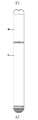
도 1은 본 발명의 실시예의 전자담배 정면도,
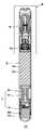
도 2는 도 1 중 A-A 부분의 단면도,
도 3은 도 2 중 M 부분의확대도,
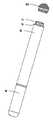
도 4는 본 발명의 실시예의 전자담배 흡입로드 분해도,
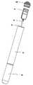
도 5는 본 발명의 실시예의 전자담배배터리로드 단면도,
도 6은 본 발명의 실시예에서, 흡입로드 내의 담배액상 카트리지의 카트리지 커버 제1 입체도,
도 7은 본 발명의 실시예에서, 흡입로드 내의 담배액상 카트리지의 카트리지 커버 제2 입체도,
도 8은 본 발명의 실시예의 흡입로드 내의 담배액상 카트리지의 카트리지전자시트 단면도,
도 9는 본 발명의 실시예의 흡입로드의 수맞물림부재 입체도,
도 10은 본 발명의 실시예의 흡입로드의 수맞물림부재 단면도,
도 11은 본 발명의 실시예의 배터리로드의 암 맞물림부재 입체도,
도 12는 본 발명의 실시예의 배터리로드의 암 맞물림부재 단면도,
도 13은 본 발명의 실시예의 흡입로드 내의 무화기 제1 전극부재 입체도,
도 14는 본 발명의 실시예의 배터리로드 내의 배터리 제1 전극부재 입체도,
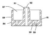
도 15는 본 발명의 실시예의 배터리로드 내의 커넥터시트 제1 입체도,
도 16은 본 발명의 실시예의 배터리로드 내의 커넥터시트 제2 입체도,
도 17은 본 발명의 실시예에서 USB 커넥터가 커넥터시트 내에 설치된 상태도,
도 18은 도 17의 단면도,
도 19는 본 발명의 실시예에서 USB 커넥터가 커넥터시트로부터 분리된 상태도,
도 20은 도 19의 단면도,
도 21은 본 발명의 실시예의 밑뚜껑을 배터리로드로부터 분리한 상태도,
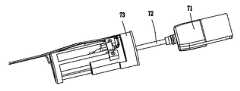
도 22는 본 발명의 실시예의 USB 커넥터를 배터리로드로부터 분리한 상태도,
도 23은 본 발명의 실시예의 흡입로드를 배터리로드로부터 분리한 상태도.1 is a front view of an electronic cigarette according to an embodiment of the present invention;
Fig. 2 is a sectional view of the AA portion in Fig. 1,
3 is an enlarged view of a portion M in Fig. 2,
4 is an exploded view of the electronic cigarette aspirating rod of the embodiment of the present invention,
5 is a sectional view of the electronic cigarette battery rod of the embodiment of the present invention,
Fig. 6 is a perspective view of the cartridge cover first stereogram of the tobacco liquid cartridge in the suction rod,
Fig. 7 is a diagram showing, in an embodiment of the present invention, a cartridge cover second stereogram of a tobacco liquid cartridge in a suction rod,
8 is a sectional view of the cartridge electronic sheet of the cigarette liquid cartridge in the suction rod of the embodiment of the present invention,
Fig. 9 is a three-dimensional view of a number engaging member of a suction rod of an embodiment of the present invention,
10 is a cross-sectional view of a male engaging member of a suction rod of an embodiment of the present invention,
11 is a three-dimensional view of the female engaging member of the battery rod of the embodiment of the present invention,
12 is a sectional view of the female engaging member of the battery rod in the embodiment of the present invention,
13 is a three-dimensional view of the atomizer first electrode member in the suction rod of the embodiment of the present invention,
14 is a three-dimensional view of the battery first electrode member in the battery rod of the embodiment of the present invention,
15 is a first three-dimensional view of the connector sheet in the battery rod of the embodiment of the present invention,
16 is a second perspective view of the connector sheet in the battery rod of the embodiment of the present invention,
FIG. 17 is a view showing a state in which the USB connector is installed in the connector sheet in the embodiment of the present invention,
Fig. 18 is a sectional view of Fig. 17,
19 is a state in which the USB connector is separated from the connector sheet in the embodiment of the present invention,
Fig. 20 is a sectional view of Fig. 19,
21 is a state in which the bottom lid of the embodiment of the present invention is separated from the battery rod,
22 is a state in which the USB connector of the embodiment of the present invention is separated from the battery rod,
23 is a state in which the suction rod of the embodiment of the present invention is separated from the battery rod.
도 1 내지 도 23에 도시된 바와 같이, 본 발명의 제1 실시예는 일종의 전자담배를 제공한다. 상기 전자담배는 전자담배 흡입로드(90)와 배터리로드(91)로 구성되는 담배로드를 포함하고, 담배로드 내에 신축 가능한 커넥터 어셈블리(7)가 감춰지도록 설치된다. 상기 커넥터 어셈블리(7)는 상기 담배로드 내에 신축 가능하게 내장되어, 사용하지 않을 때, 담배로드 내에 완전히 수용되어 감춰질 수 있으며, 사용 시 담배로드에서 뽑아 길이를 당기면 기타 전자장치 또는 전원과 전기적으로 접속시킬 수 있다. 상기 커넥터 어셈블리(7)의 주요 역할은 전자담배를 충전시키기 위한 것이다. 전자담배 내에 부가된 다양한 기능을 만족시키도록 멀티미디어 데이터를 다운로드하는 등과 같이 데이터를 전송하는데 사용될 수도 있다. 상기 커넥터 어셈블리(7)는 적어도 하나의 커넥터(71) 및 길이를 늘일 수 있는 도선(72)을 포함한다. 전자담배의 기능 요구에 따라, 커넥터(71)는 USB형, 페그(peg)형, 핀형 또는 기타 적당한 커넥터 형식으로 설계할 수 있다. 이하 바람직한 실시방식에서는 USB 커넥터(71)로 전자담배를 충전하는 기능을 상세히 설명한다.1 to 23, the first embodiment of the present invention provides a kind of electronic cigarette. The electronic cigarette includes a cigarette rod composed of an electronic
도 2 내지 도 4에 도시된 바와 같이, 상기 흡입로드(90)는 흡입통(1), 담배액상을 연무로 무화시키기 위한 무화장치(2), 담배액상을 저장하기 위한 담배액상 카트리지(3), 마우스피스(4) 및 상기 배터리로드(91)와 상호 결합되는 수 맞물림부재(5)를 포함한다. 본 실시예에서, 상기 흡입통(1)은 가운데가 통하는 일자형 통체 구조로서, 마우스피스(4)와 수 맞물림부재(5)가 각각 흡입통(1)의 양단에 설치된다.2 to 4, the
도 3에 도시된 바와 같이, 상기 마우스피스(4)는 대체로 원통형의 본체(41)를 포함하며, 본체(41) 내부의 중공에 축방향을 따라 관통되는 통기홀(42)이 형성된다. 마우스피스(4)는 탄성 재질로 제작되며, 상기 흡입통(1)의 상단에 뽑아서 분리할 수 있게 삽입 설치된다.3, the dental mouthpiece 4 includes a generally cylindrical main body 41, and a
도 3, 4, 9 및 10에 도시된 바와 같이, 수 맞물림부재(5)는 대체로 중공의 컵 형태이며, 외부 공기가 흡입통(1) 내로 진입할 수 있도록 그 저단 측벽에 방사상으로급기홀(51)이 설치되고, 저단은 방사상으로 바깥을 향해 흡입통(1)의 저단과 서로 맞닿는 위치결정턱(52)이 돌출되게 형성된다. 맞물림부재(5) 저부는 상기 배터리로드(91)와 상호 삽입 결합되어 긴밀히 정합되도록 하기 위한 수납챔버(53)를 한정한다.맞물림부재(5)의 중간부분에 축방향을 따라 관통되는 전극부재홀(54) 및 통기홀(55)이 개설되고, 맞물림부재(5)의 저부에 상기 배터리로드(91)와 상호 삽입 결합되도록 축방향을 따라 돌출되는 위치결정 돌출부(56)가 설치된다.As shown in Figs. 3, 4, 9 and 10, the
도 3, 4 및 13에 도시된 바와 같이, 흡입통(1) 내에 배터리로드(91) 내부의 전극과 전기적으로 접속되기 위한 무화기 제1 전극부재(17) 및 무화기 제2 전극부재(19)가 더 설치된다. 상기 무화기 제1 전극부재(17)와 무화기 제2 전극부재(19)는 모두 상기 수 맞물림부재(5) 내에 고정되며, 상기 무화기 제1 전극부재(17)는 탄성 변형을 갖는 금속 도전성 박편으로서, 그 일단은 용접홀이 설치된 용접플레이트(171)이고, 타단은 탄성 변형이 생길 수 있는 접속 플레이트(172)이며, 중간부분에 상기 수 맞물림부재(5) 내에 끼워져 탄성 변형이 생길 수 있는 체결 플레이트(173)가 설치된다. 상기 무화기 제2 전극부재(19)와 상기 무화기 제1 전극부재(17)의 구조는 동일하다. 무화기 제1 전극부재(17)와 무화기 제2 전극부재(19)는 그 용접 플레이트(171) 및 용접홀을 통해 아래에 설명할 가열소자(211)의 양, 음 전극과 각각 전기적으로 접속된다.The atomizer
도 3 내지 5에 도시된 바와 같이, 상기 무화장치(2)는 흡입로드(90) 내에 설치되는 무화기(21), 무화기 스위치(27)와 스위치시트(28) 및 무화기(21)의 작동을 제어하기 위한 제어회로유닛을 포함한다.3 to 5, the
상기 무화기(21)는 담배액상을 연무로 무화시키기 위한 것으로서, 가열소자(211) 및 섬유부재(212)를 포함한다. 상기 가열소자(211)는 상기 섬유부재(212)에 권취되어, 상기 섬유부재(212)를 이용하여 상기 담배액상 카트리지(3) 내에 수납 고정된다. 상기 섬유부재(212)는 가열소자가 담배액상을 가열하여 무화시킬 수 있도록 담배액상을 흡수하기 위한 것으로서, 섬유부재(212)는 스폰지처럼 액체를 흡수 및 저장할 수 있고, 유리섬유 또는 면재질과 같이 액체를 흡수 및 격리하는 성능을 구비한 재료로 제조되며, 그 형상은 원기둥 형상으로, 본 실시예에서는 3개의 섬유부재(212)를 설치하였으며, 3개의 섬유부재(212)는 전체가 담배액상 카트리지(3) 내에 설치된다. 가열소자(211)는 3개(단 3개로 한정되지 않는다)의 섬유부재(212) 외측에 권취되며, 가열소자(211)의 양단은 각각 담배액상 카트리지(3)를 관통하여 상기 수 맞물림부재(5) 내의 무화기 제1 전극부재(17) 및 무화기 제2 전극부재(19)와 전기적으로 접속된다.The
도 3, 4에 도시된 바와 같이, 상기 담배액상 카트리지(3)는 카트리지 시트(31), 카트리지 커버(33), 도관(35), 담배액상 저장부재(37) 및 위치결정튜브(39)를 포함한다. 그 중, 카트리지시트(31)와 카트리지 커버(33)는 서로 대향하며 또한 일정 간격만큼 이격되게 흡입통(1) 내벽에 고정되고, 도관(35)은 카트리지 시트(31)와 카트리지 커버(33) 사이에 고정되며, 액상 저장부재(37)는 도관(35) 외측에 고정되면서 카트리지 시트(31)와 카트리지 커버(33) 사이에 위치한다. 위치결정튜브(39)는 상기 무화기(21)를 정위시키기 위한 것이다.3 and 4, the tobacco liquid cartridge 3 includes a
본 실시예에서, 상기 카트리지 시트(31)(도 3, 4 및 8)는 원통형의 컵체로서, 고리형 측벽(318), 원형 카트리지 바닥(319), 카트리지 바닥(319)의 중간부분으로부터 축방향을 따라 연장되어 상기 도관(35)을 정위시키기 위한 도관 위치결정기둥(311)을 포함한다. 그 중 고리형 측벽(318)과 도관 위치결정기둥(311) 사이가 하나의 고리형 내부 캐비티(317)를 한정하고, 축방향을 따라 도관 위치결정기둥(311)과 카트리지 바닥(319)을 관통하는 카트리지 시트 통기홀(312)이 형성되며, 카트리지 바닥(319) 내에 가열소자(211)가 관통되도록 하기 위한 2개의 관통홀(313)이 설치된다. 측벽(318) 외측에 흡입통(1)과 밀착 결합되도록 하기 위한 텐션링(314)이 설치되어, 카트리지 시트(31)가 그 측벽(318) 및 텐션링(314)을 이용하여 상기 흡입통(1)의 내벽에 밀착 고정된다.In this embodiment, the cartridge sheet 31 (Figs. 3, 4 and 8) is a cylindrical cup body having an
상기 카트리지 커버(33)(도 3, 4, 6 및 7 참조)는 실리콘 재질로 제작될 수 있으며, 그 형상과 크기는 상기 흡입통(1)의 내벽과 일치한다. 본 실시예에서, 이는 중공의 원형 마개 구조이며, 측벽(338), 상부 벽(339)을 포함하여, 측벽(338)과 상부 벽(339)이 함께 하나의 고리형 내부 캐비티(337)를 한정하며, 연무 기체가 통하도록 상기 고리형 내부 캐비티의 내경이 상기 도관(35)의 외경보다 크다. 상기 측벽(338)에 통기홀(336)이 개설되어 상기 고리형 내부 캐비티(337)와 서로 통하며, 상기 상부 벽(339)에 돌출리브(335)가 설치된다. 본 실시예에서는 상부 벽 중심을 따라 균일하게 분포되는 3개의 돌출리브(335)를설치하였으며, 도관(35)이 돌출리브(335)와 맞닿았을 때, 도관(35)의 상단과 상부 벽(339) 사이에 간격이 구비되어 통기홈(334)이 형성되며, 상기 통기홈(334)은 상기 고리형 내부 캐비티(337)와 서로 연통된다. 측벽(338)의 저부는방사상으로 바깥을 향해 플랜지(333)가 돌출되며, 플랜지(333)의 가장자리에 담배액상을 주입하기 위한 약간의 호형 개구(332)가 형성되어, 플랜지(333)가 대체로 톱니 형상을 이루며, 플랜지(333)의 외경이 흡입통(1)의 내경보다 약간 커, 카트리지 커버(33)가 플랜지(333)를 이용하여 상기 흡입통(1)의 내벽에 긴밀히 고정된다. 상기 카트리지 커버(33)의 고리형 내부 캐비티(337)는 카트리지 시트(31)의 도관 위치결정기둥(311)과 대응하여, 각각 도관(35)의 양단을 고정한다. 상기 카트리지 커버(33)의 플랜지(333)와 카트리지 시트(31)의 고리형 내부 캐비티(317)는 각각 액상저장부재(37)의 양단을 고정한다. 담배액상 카트리지(3) 내의 담배액상 사용이 완료되면, 카트리지 커버(33)를 분리할 필요 없이 마우스피스(4)를 분리하여, 담배액상을 카트리지 커버(33)의 호형 개구(332)로부터 담배액상 카트리지(3) 내로 주입하기만 하면 되며, 담배액상이 상기 액상저장부재(37)에 의해 흡수되어 담배 액상을 여러 번 주입할 수 있을 뿐만 아니라 사용이 간편하다.The cartridge cover 33 (see FIGS. 3, 4, 6 and 7) can be made of a silicone material, and its shape and size coincide with the inner wall of the suction cylinder 1. In this embodiment, it is a hollow, circular stop structure and includes
상기 도관(35)(도 3, 도 4 참조)은 담배액상 카트리지(3)의 높이를 제어하고 상기 섬유부재(212)를 지지하기 위한 것으로서, 담배액상이 상기 무화기(2)에 의해 무화되어 발생하는 연무가 흡입통(1) 외부로 통하게 하는 통로 역할도 한다. 본 실시예에서, 도관(35)은 중심 관통홀을 구비한 절연성 공심원형튜브로서, 플라스틱 또는 섬유재질, 예를 들어 유리섬유튜브로 제조될 수 있으며, 상부 및 저부를포함하여,상부는 상기 카트리지 커버(33)의 고리형 내부 캐비티(337) 내에 설치되고, 그 저부는 상기 카트리지 시트(31)의 도관 위치결정기둥(311)에 끼워져 그 주위와 밀봉 결합된다. 상기 섬유부재(212)를 지지 및 고정하도록, 도관(35)에 방사상으로 도관(35) 측벽을 관통하는 끼움홈(351)이 설치되며, 상기 섬유부재(212)가 상기 끼움홈(351)에 장착되어 액상 저장부재(37)와 서로 맞닿음으로써 담배액상을 흡수하여 상기 가열부재(211)가 무화시킬 수 있도록 제공한다.3 and 4) are for controlling the height of the tobacco liquid cartridge 3 and for supporting the
상기 액상저장부재(37)(도 3, 도 4 참조)는 담배액상 카트리지(3) 내에 주입된 담배액상을 무화기(21)가 이어서 무화시킬 수 있도록 흡수하고 저장하기 위한 것으로서, 스폰지처럼 액체를 흡수하고 저장할 수 있으며, 면재질 또는 섬유재질과 같이 액체를 흡수 및 격리하는 성능을 갖는 재료로 제작될 수 있다. 액상저장부재(37)는 가운데가 통하는 원통체 구조로서, 상기 도관(35)의 외측에 끼워져 도관(35)의 외벽과 밀착되어 지지되며, 그 일단은 카트리지 시트(31)의 고리형 내부 캐비티(317) 내에 삽입되고, 타단은카트리지 커버(33)의 플랜지(333)에 맞닿음으로써, 카트리지 시트(31)와 카트리지 커버(33) 사이에 고정된다. 상기 섬유부재(212)의 양단은 액상 저장부재(37)의 내벽과 서로 맞닿음으로써, 가열소자(211)가 연무로 무화시키기 유리하도록 담배액상을 상기 액상저장부재(37)로부터 상기 섬유부재(212) 내로 흡착한다.3 and 4) is for absorbing and storing the tobacco liquid phase injected into the liquid tobacco cartridge 3 so that the
상기 위치결정튜브(39)(도 3, 도 4 참조)는 상기 도관(35) 상에서 상기 무화기(21)의 위치를 한정하기 위한 것으로서, 위치결정튜브(39)는 상기 도관(35)과 서로 일치하는 절연성 공심 원형튜브이며, 플라스틱 또는 섬유재질, 예를 들어 유리섬유튜브로 제작될 수 있으며, 위치결정튜브(39)는 상기 도관(35)의 외벽에 끼워지고, 위치결정튜브(39)와 도관(35)은 억지 끼워맞춤 결합되며, 위치결정튜브(39)의 저단은 상기 무화기(21)와 서로 맞닿음으로써, 무화기(21)가 도관(35)을 따라 축방향으로 이동하는 것을 방지한다.The positioning tube 39 (see FIGS. 3 and 4) is for defining the position of the
본 실시예에서, 담배액상 카트리지(3) 내의 연무통로는 카트리지 시트(31)의 카트리지 시트 통기홀(312), 도관(35)의 중심관통홀 및 카트리지 커버(33) 내부에 형성된 통기홈(334), 고리형 내부 캐비티(337) 및 통기홀(336)이 공동으로 한정한다.In this embodiment, the mist passage in the tobacco liquid cartridge 3 includes the cartridge
도 2, 3 및 5에 도시된 바와 같이, 상기 배터리로드(91)는 슬리브(910), 슬리브(910) 양단에 각각 설치되는 암 맞물림부재(911) 및 밑뚜껑(912), 슬리브(910) 내에 수납되는 배터리(913), 배터리(913)의 두 전극과 각각 전기적으로 접속되기 위한 배터리 제1 전극부재(914)와 배터리 제2 전극부재(915)를 포함한다.2, 3 and 5, the
도 3, 11 및 12에 도시된 바와 같이, 상기 암 맞물림부재(911)와 상기 수 맞물림부재(5)는 서로 매칭되며, 탄성 플라스틱 재질로 제작된다. 암 맞물림부재(911)는 흡입로드(90)와 배터리로드(91)가 서로 결합되도록 상기 슬리브(910)의 상단에 설치되며, 암 맞물림부재(911)는 대체로 원형 마개 구조로서, 측벽(9111)과 상부 벽(9112)을 포함하여, 측벽(9111)과 상부 벽(9112)이 공동으로 하나의 내부 캐비티(9119)를 형성하며, 측벽(9111) 상의 상부 벽(9112)에 가까운 위치에 암 맞물림부재(911)의 반경방향을 따라 바깥을 향해 상기 슬리브(910)와 서로 정합되는위치결정단턱(9113)이 돌출되고, 상부 벽(9112)에 암 맞물림부재(911)의 축방향을 따라 바깥을 향해 상기 수 맞물림부재(5)의 수납 캐비티(53)와 서로 정합되는 삽입 기둥(9114)이 돌출되며, 상부 벽(9112)에 상부 벽(9112) 표면으로부터 내측으로 함몰되어 상기 수 맞물림부재(5)의 위치결정 돌출부(56)와 서로 정합되는위치결정오목홈(9115)이 더 설치되고, 암 맞물림부재(911) 내에 축방향을 따라 도선이 관통되기 위한 관통홀(9116)이 더 설치되며, 암 맞물림부재(911) 내에 축방향을 따라 연장되어 상기 배터리 제1 전극부재(914)와 배터리 제2 전극부재(915)를 고정시키기 위한 2개의 전극부재 끼움홈(9117) 및 내부 캐비티(9118)가 더 설치된다. 상기 내부 캐비티(9118)는 상기 무화기 제1 전극부재(17)와 무화기 제2 전극부재(19)가 각각 그 내부에 삽입되어 각각 상기 배터리 제1 전극부재(914) 및 배터리 제2 전극부재(915)와 탄성적으로 맞닿게 하기 위한 것이다.3, 11 and 12, the
도 2, 5에 도시된 바와 같이, 상기 밑뚜껑(912)은 상기 USB 커넥터(71)를 밀봉하기 위해 슬리브(910)의 바닥 단부에 설치되며, 밑뚜껑(912)에 밀봉링(916)이 더 설치된다. 상기 밑뚜껑(912)이 슬리브(910)로부터 탈락되거나 또는 뚜껑을 연 후 유실되는 것을 방지하기 위해, 밑뚜껑(912)에 연결끈을 설치하여 슬리브(910)에 연결할 수 있으며, 상기 연결끈은슬리브(910) 내에 설치할 수도 있고, 또는 일체형으로 성형된 연결부 등 기타 연결형식을 통해 밑뚜껑(912)을 슬리브(910)에 연결할 수 있음은 이해할 수 있을 것이다.2 and 5, the
도 3, 4 및 14에 도시된 바와 같이, 상기 배터리 제1 전극부재(914)와 배터리 제2 전극부재(915)는각각 상기 암 맞물림부재(911)의 전극부재 끼움홈(9117) 내에 고정되며, 상기 배터리 제1 전극부재(914)는 탄성 변형을 갖는 금속 도전성 박편으로서, 그 일단은 용접홀이 설치된 용접 플레이트(9141)이고, 타단에는 탄성 변형이 생길 수 있는 접속 플레이트(9142)가 설치되며, 중간부분에 상기 암 맞물림부재(911) 내에 끼워져 탄성 변형을 일으킬 수 있는 체결 플레이트(9143)가 설치된다. 상기 배터리 제2 전극부재(915)는 상기 배터리 제1 전극부재(914)의 구조와 동일하다. 흡입로드(90)와 배터리로드(91)가 서로 삽입 결합될 때, 암 맞물림부재(911) 내에 설치된 상기 배터리 제1 전극부재(914)와 상기 배터리 제2 전극부재(915)가 각각 상기 수 맞물림부재(5) 내에 설치된 무화기 제1 전극부재(17) 및 무화기 제2 전극부재(19)와 서로 탄성적으로 맞닿아 전기적인 접속을 실현한다. 배터리 제1 전극부재(914), 배터리 제2 전극부재(915)는 그 용접 플레이트(9141) 및 용접홀을 통해 상기 배터리(913)의 양, 음 전극과 각각 전기적으로 접속되고, 무화기 제1 전극부재(17), 제2 전극부재(19)와 배터리 제1 전극부재(914), 제2 전극부재(915) 사이는 각각 그 굴절된 접속 플레이트 사이를 통해 서로 탄성적으로 맞닿음으로써 전기적으로 접속된다. 이러한 삽입 결합 방식으로 전기적인 접속을 실현하면 공정이 단순해지고, 장착이 간편할 뿐만 아니라 선로의 연결이 안정적이다.3, 4 and 14, the battery
도 3, 5에 도시된 바와 같이, 본 실시예에서, 상기 무화기 스위치(27)와 스위치시트(28)는 상기 배터리로드(91) 내에 설치되고, 무화기 스위치(27)는 상기 스위치시트(28) 내에 고정되며, 상기 스위치시트(28)는 상기 암 맞물림부재(911)의 내부 캐비티(9119) 내에 고정된다. 상기 무화기 스위치(27)의 2개의 전극은 2가닥의 도선(도면 중 부호 미표기)을 이용하여 각각 상기 배터리 제1 전극부재(914) 및 배터리 제2 전극플레이트(915)와 전기적으로 접속된다. 무화기 스위치(27)는 기체가 진동함에 따라 회로가 도통되는 공압 스위치로서, 무화기 스위치(27)를 이용하여 무화기(21)의 통전 또는 단전을 제어한다. 무화기 스위치(27)와 상기 배터리(913)는 모두 상기 제어회로유닛과 전기적으로 접속된다.3 and 5, in the present embodiment, the
도 2, 도 5 및 도 15 내지 22에 도시된 바와 같이, 상기 커넥터 어셈블리(7)는 USB 커넥터(71), 도선(72) 및 커넥터시트(73)를 포함한다. 본 실시예에서는 상기 커넥터 어셈블리(7)를 상기 배터리로드(91) 내에 설치하였다.2, 5, and 15-22, the connector assembly 7 includes a
상기 USB 커넥터(71)는 외부 전원과 전기적으로 접속되어 상기 배터리(911)를 충전하기 위한 것이다. 물론, 전자담배 내에 이동저장장치, MP3 또는 MP4 등 하나 또는 다수의 기능이 더 설치되거나 또는 단독으로 설치될 수 있다. 즉 USB 커넥터(71)는 전자담배 내에 추가되는 다양한 기능을 만족하도록 멀티미디어 데이터 등을 전송, 다운로드 또는 저장하는데 사용될 수도 있다. 상기 USB 커넥터(71)는 상기 커넥터시트(73)에 의해 상기 배터리로드(91) 내에 고정된다.The
도 15 내지 22에 도시된 바와 같이, 상기 커넥터시트(73)는 대체로 원통체 형상이며, 커넥터시트(73) 내에 USB 커넥터(71)와 도선(72)을 수납하기 위한 제1수납 캐비티(731)가 설치되고, 커넥터시트(73)에 상기 도선(72)을 고정시키기 위한 도선 위치결정부재(735)가 더 설치된다. 본 실시예에서, 도선 위치결정부재(735)는 커넥터시트(73)의 외벽에 위치하며 내부 나사산홀을 구비한 2개의 나사기둥이다. 상기 커넥터시트(73)의 선단 측벽에 상기 슬리브(910)의 바닥 단부와 서로 일치하는 위치결정단턱(736)이 더 설치된다. 커넥터시트(73)의 말단부에 바닥판(737)이 더 설치되며, 상기 바닥판(737)에 상기 도선(72)이 관통하기 위한 관통홀(738) 및 개구(739)가 미리 마련되고, 커넥터시트(73)의 외벽에 도선(72)이 지나는 도선통과홈(미도시)이 미리 마련된다.15 to 22, the
본 실시예에서, 상기 제1 수납 캐비티(731)는 순차적으로 연통되는 전단부(7311), 중간단부(7312) 및 후단부(7313)를 포함하며, 전단부(7311)는 원통형으로, 상기 USB 커넥터(71)와 도선(72)이 커넥터시트(73) 바깥으로 뻗어 나오거나 또는 커넥터시트(73) 내로 진입하도록 하기 위한 것이다. 중간단부(7312)는 대체로 사각통형 또는 기타 형상으로, 전단부(7311)의 바닥벽으로부터축방향을 따라 전단부(7311)에서 먼 방향으로 연장되게형성되어, 상기 USB 커넥터(71)가 그 내부에 수납되어 감입되며, 후단부(7313)는 주로 상기 도선(72)을 수납하고 도선(72)이 그 내부에서 신축 이동할 수 있도록 하기 위한 것으로서, 2개의 서로 평행하게 축방향을 따라 연장되는 끼움판(미도시)과 상기 바닥판(737)에 의해 한정된다. 물론, 후단부(7313)는 중공의 원통체 또는 기타 형상일 수도 있으며, 도선(72)을 수납하고 도선(72)이 왕복 삽입되어 자유롭게 이동할 수있으면 된다. 중간단부(7312)와후단부(7313) 사이에 도선(72)이 관통되는 관통홀이설치되고, 상기 전단부(7311)의 외벽은 또한 상기 슬리브(910)의 내벽과 서로 일치하여, 커넥터시트(73)가 전단부(7311)의 외벽을 통해 상기 슬리브(910)와 긴밀히 정합되어 커넥터시트(73)를 상기 슬리브(910) 내에 고정시키며, 또한 상기 위치결정단턱(736)을 이용하여 정위시킨다(도 2, 도 21, 도 22 참조). 본 실시예에서, 상기 도선 위치결정부재(735)는 상기 제1 수납 캐비티(731)의 중간단부(7312)의 외벽에 위치하며,커넥터시트(73)와 일체로 형성된다.The
상기 도선(72)의 일단은 USB 커넥터의 길이를 연장시키도록 USB커넥터(71)와 연결되고, 타단은 충전 또는 기타 기능을 실현하도록 제어회로유닛과 전기적으로 접속된다. 도선(72)은 일체를 형성하도록 연결된 이동도선(721)과 고정도선(722)을 포함하며, 양자 사이에 조인트(723)가 설치되어 맞물린다. 조인트(723)는 수납 캐비티(731)의 내벽 또는 외벽과 고정되어 고정도선(722)을 고정시킨다. 이동도선(721)의 일단은 상기 조인트(723)에서 상기 고정도선(722)과 전기적으로 접속되며, 이동도선(721)의 타단은 상기 USB 커넥터(71)와 전기적으로 접속된다. 상기 고정도선(722)의 일단은 상기 조인트(723)에서 상기 이동도선(721)과 전기적으로 접속되고, 타단은커넥터시트(73)의 외벽에 부착되어 상기 도선통과홈을 따라 상기 개구(739)를 관통한 후 상기 제어회로유닛과 전기적으로 접속된다. 고정도선(722)은 배터리로드(91) 내에 고정되어 신축 운동을 할 수 없으며, 상기 조인트(723)는 대체로 U자형으로서, 그 양측에 각각 상기 도선 위치결정부재(735)와 서로 정합되는 위치결정홀이 설치되어, 조인트(723)가 그 위치결정홀을 이용하여 상기 도선 위치결정부재(735)에 끼워진 다음, 나사를 이용하여 조인트(723)가 상기 도선 위치결정부재(735)와 결합되어 긴밀히 고정된다. 조인트(723)는 기타 형상으로 설계할 수도 있으며, 그 고정방식은 이동도선(721)을 당겼을 때 도선(72)과 제어회로유닛 사이의 전기적인 접속을 분리시키지 않도록 끼움 결합 등 기타 방식으로 도선(72)의 고정도선부분을 고정할 수도 있음을 이해할 수 있을 것이다.One end of the
커넥터 어셈블리(7)를 사용하지 않을 때, 수동으로 USB 커넥터(71)를 눌러 USB 커넥터(71)를 커넥터시트(73) 내로 삽입하고, 상기 밑뚜껑(912)을 닫으면, 이때 이동도선(721)은 상기 도선 수납홈(732) 내에 위치하게 된다(도 18 참조). 커넥터 어셈블리(7)를 사용해야 할 때, 먼저 밑뚜껑(912)을 분리한 다음, USB 커넥터(71)를 커넥터시트(73) 내로부터 인출하면, USB 커넥터(71)가 커넥터시트(73)로부터 분리되어 슬리브(910) 바깥으로 뻗어 나오는데, 이때 이동도선(721)의 일단이 USB 커넥터(71)를 따라 상기 제1 수납 캐비티(731)를 거쳐 슬리브(910) 외측으로 뻗어 나오게 되며(도 20 참조), 이동도선(721)으로 상기 USB 커넥터(71)를 필요한 길이만큼 연장시켜 외부 전자장치 또는 전원과 접속시킨다. 본 실시예에서, 상기 고정도선(722)은 각각 양극선, 음극선 및 신호선인 3가닥으로 구분되어, 각각 제어회로유닛의 관련 전극과 전기적으로 접속된다. USB 커넥터(71)와 도선(72)은 배터리로드(91) 내부에 설치되어 사용이 간편하며 또한 미관적이다. 커넥터시트(73) 내에 USB 커넥터(71)와 도선(72)이 수납되기 위한 상기 제1 수납 캐비티(731)가 설치되어, 사용 시 USB 커넥터(71)와 도선(72)이 자유롭게 신축될 수 있다.When the connector assembly 7 is not used, the
상기 전자담배 흡입로드(90)와 배터리로드(91)의 결합방식은 끼움결합 또는 삽입결합이다. 도 23에 도시된 바와 같이, 본 실시예에서는 삽입 결합 방식을 채택하여, 담배 흡입로드(90)와 배터리로드(91)가 상기 수 맞물림부재(5)와 암 맞물림부재(911)를 이용하여 삽발형으로 긴밀히 결합됨과 아울러 탈착이 가능하며, 그 탈착이 간편하고 신속하다. 본 발명의 전자담배는 흡입로드(90)의 흡입통(1)과 배터리로드(91)의 슬리브(910)가 일체로 성형된 하우징인 일체형 전자담배일 수도 있음은 이해할 수 있을 것이다. 또한, 흡입통(1), 슬리브(910)와 마우스피스(4) 역시 일체형으로 성형될 수 있다.The electronic
이상은 본 발명의 구체적인 실시방식을 설명한 것이며, 지적해두어야 할점으로, 본 기술분야의 보통 기술자라면, 본 발명의 원리를 벗어나지 않는다는 전제 하에 약간의 개선 및 수식을 더 실시할 수 있으며, 이러한 개선과 수식 역시 본 발명의 보호범위로 간주되어야 한다.
It will be apparent to those skilled in the art that various modifications and variations can be made in the present invention without departing from the spirit and scope of the invention as defined by the appended claims. The formula should also be regarded as the scope of protection of the present invention.
Claims (15)
Translated fromKorean담배로드, 및
커넥터 어셈블리를 포함하며,
그 중, 상기 커넥터 어셈블리는 담배로드 내부에 신축 가능하게 감춰지도록 설치되며, 상기 커넥터 어셈블리는 커넥터 및 길이를 늘일 수 있는 도선을 포함하고, 상기 도선은 인출 가능하게 상기 담배로드 내에 수납되어, 일단은 커넥터와 연결되고, 타단은 담배로드 내의 회로제어유닛과 전기적으로 접속되고, 상기 커넥터는 인출 가능하게 상기 담배로드 내에 수납되어 상기 길이를 늘일 수 있는 도선을 통해 담배로드 외부로 일정 길이만큼 연장되어, 커넥터 어셈블리를 사용하지 않을 때, 상기 도선을 접어 커넥터와 함께 상기 담배로드 내에 감춰지도록 수납하고, 커넥터 어셈블리를 사용해야 할 때, 커넥터를 뽑아 도선을 필요한 길이만큼 늘임으로써, 커넥터로 전자담배를 외부 전자장치 또는 전원과 전기적으로 접속시키고,
상기 커넥터 어셈블리는 담배로드 내에 설치되어 상기 커넥터를 수납 및 고정시키기 위한 커넥터시트를 더 포함하며, 상기 커넥터시트 내에 상기 커넥터와 도선을 수납하기 위한 제1 수납챔버가 설치되고, 상기 제1 수납챔버의 벽체는 상기 커넥터와 도선이 커넥터시트의 바깥으로 인출되거나 또는 커넥터시트 내로 인입되도록 하기 위한 원통형의 전단부를 포함하며, 상기 원통형 전단부는 담배로드 내벽과 서로 정합되며,
그 중 상기 도선은 일체를 형성하도록 연결된 이동도선 부분과 고정도선 부분을 포함하고, 둘 사이는 조인트가 설치되어 맞물리며, 상기 조인트는 상기 커넥터시트에 고정되고, 이동도선 부분의 일단이 상기 조인트 부위에서 상기 고정도선 부분과 전기적으로 접속되어, 상기 도선이 이동도선 부분의 타단을 통해 상기 커넥터와 전기적으로 접속되며, 상기 고정도선 부분의 일단은 상기 조인트에 의해 커넥터시트에 고정되어 상기 이동도선 부분과 전기적으로 접속되고, 상기 도선은 고정도선 부분의 타단을 통해 상기 담배로드 내의 제어회로 유닛과 전기적으로 접속되는 전자담배.
As a kind of electronic cigarette,
Tobacco load, and
A connector assembly,
Wherein the connector assembly is installed so as to be retractable within a tobacco rod, the connector assembly comprising a connector and a conductor capable of extending in length, the conductor being housed in the tobacco rod so as to be withdrawn, And the other end is electrically connected to a circuit control unit in the tobacco rod, and the connector is extendably extended to the outside of the cigarette rod through a lead that can be taken out of the cigarette rod so as to be drawn out, When the connector assembly is not in use, the lead is folded together with the connector so as to be hidden in the tobacco rod, and when the connector assembly is to be used, the connector is pulled to extend the lead wire by a required length, Or power source,
Wherein the connector assembly further comprises a connector sheet installed in the tobacco rod for receiving and fixing the connector, wherein a first accommodating chamber for accommodating the connector and the lead wire is provided in the connector seat, The wall includes a cylindrical front end for allowing the connector and the lead to be pulled out of the connector seat or into the connector seat, the cylindrical front end being aligned with the tobacco rod inner wall,
Wherein the conductor comprises a moving conductor portion and a fixed conductor portion connected to form an integral body, a joint is provided and engaged, the joint is fixed to the connector sheet, and one end of the moving conductor portion is connected to the joint portion And the conductive wire is electrically connected to the connector through the other end of the movable conductive wire portion, and one end of the fixed conductive wire portion is fixed to the connector sheet by the joint, And the lead wire is electrically connected to the control circuit unit in the tobacco rod via the other end of the fixed lead wire portion.
상기 커넥터시트의 상부에 상기 조인트를 고정시키기 위한 도선 위치결정부재가 설치되고, 이와 대응되게, 상기 조인트에 상기 도선 위치결정부재와 서로 정합되는 위치결정홀이 설치되어, 조인트가 그 위치결정홀을 이용하여 상기 도선 위치결정부재에 끼워져 고정되며, 상기 커넥터시트의 원통형 전단부 외벽에 상기 담배로드와 서로 정합되는 위치결정 단턱이 더 설치되어, 커넥터시트가 상기 담배로드 내에 삽입되고, 상기 원통형 전단부 외벽은 담배로드의 내벽과 밀착 고정되어 상기 위치결정 단턱을 이용하여 정위되는 전자담배.
The method according to claim 1,
Wherein the connector sheet is provided with a wire positioning member for fixing the joint, and correspondingly, the positioning hole is aligned with the wire positioning member on the joint, And a connector seat is inserted into the tobacco rod, and the cylindrical front end portion of the connector seat is fixed to the cylindrical front end portion of the connector seat, Wherein the outer wall is closely fixed to the inner wall of the tobacco rod and is positioned using the positioning step.
상기 커넥터는 USB 커넥터 또는 페그(peg)형 또는 핀형 커넥터이고, 상기 커넥터시트는 대체로 원통형이며, 그 내부는 상기 제1 수납챔버를 한정하고, 벽체에 관통홀이 설치되며, 외벽에 도선통과홈이 설치되어, 상기 도선이 제1 수납챔버 내로부터 상기 관통홀을 관통한 후 도선통과홈을 따라 담배로드 내의 회로제어유닛과 전기적으로 접속되는 전자담배.
The method according to claim 1,
The connector is a USB connector or a peg type or a pin type connector. The connector seat is generally cylindrical, and the inside defines a first accommodating chamber, a through hole is provided in the wall, And the lead wire is electrically connected to the circuit control unit in the tobacco rod along the lead passage groove after passing through the through hole from within the first housing chamber.
상기 담배로드는 흡입로드와 배터리로드를 포함하며, 상기 흡입로드는 흡입통, 마우스피스, 흡입통 내에 설치되는 무화기 및 담배액상을 저장하기 위한 담배액상 카트리지를 포함하고, 상기 배터리로드는 슬리브, 및 슬리브 내에 설치되는 배터리와 슬리브 말단의 밑뚜껑을 포함하며, 상기 커넥터 어셈블리는 슬리브 내에 설치되고, 상기 밑뚜껑은 슬리브에 결합되어 커넥터 어셈블리를 슬리브 내에 밀봉시키는 전자담배.
The method according to claim 1,
Wherein the tobacco rod includes a suction rod and a battery rod, the suction rod including a suction cylinder, a mouthpiece, a radiator provided in the suction cylinder, and a cigarette liquid cartridge for storing a cigarette liquid phase, And a battery installed in the sleeve and a bottom lid at the end of the sleeve, wherein the connector assembly is installed in the sleeve and the bottom lid is coupled to the sleeve to seal the connector assembly in the sleeve.
상기 담배액상 카트리지는 서로 마주보면서 일정 간격으로 이격되어 흡입통 내벽에 밀착되는 카트리지 시트와 카트리지 커버, 및 상기 카트리지 시트와 카트리지 커버 사이에 고정되는 도관과 액상저장부재를 포함하여, 상기 액상저장부재가 상기 도관 외측에 끼워지고, 상기 도관 양단의 개구는 내부가 중공으로, 상기 무화기가 상기 도관에 고정 지지되며, 상기 도관 외벽에 상기 무화기가 도관을 따라 축방향으로 이동하는 것을 방지하기 위한 위치결정튜브가 더 설치되고, 상기 위치결정튜브와 도관은 억지 끼워맞춤되어 위치결정튜브와 상기 무화기가 서로 맞닿게 접속되는 전자담배.
The method according to claim 6,
Wherein the liquid cigarette liquid cartridge includes a cartridge sheet and a cartridge cover which are spaced apart from each other at a predetermined interval and come into close contact with the inner wall of the suction tube, and a conduit and a liquid storage member fixed between the cartridge sheet and the cartridge cover, And an opening at both ends of the conduit is hollow and the injector is fixedly supported on the conduit and a positioning tube is provided on the conduit outer wall to prevent the injector from moving axially along the conduit. Wherein the positioning tube and the conduit are interference fit so that the positioning tube and the applicator are in contact with each other.
상기 카트리지 시트는 원통형의 컵체 구조로서, 그 내부에 상기 도관을 정위시키기 위한 도관 위치결정기둥이 설치되고 상기 액상저장부재를 수납하기 위한 고리형 내부 캐비티가 한정되며, 상기 카트리지 커버는 대체로 원통형인 마개 구조로서, 그 내부에 상기 도관을 수납하기 위한 고리형 내부 캐비티가 한정되고, 그 측벽에 통기홀이 개설되며, 그 상부 벽에 폭이 도관의 내경보다 좁은 돌출리브가 설치되고, 카트리지 커버 저부 측벽에 방사상으로 바깥을 향해 플랜지가 연장되며, 상기 플랜지는 톱니 형상으로서, 톱니 사이의 간격으로 담배액상을 담배액상 카트리지 내로 주입하도록 다수의 톱니가 구비되며, 상기 카트리지 커버의 상부 벽과 상기 카트리지 시트의 도관 위치결정기둥은 각각 상기 도관 양단에 고정되고, 상기 카트리지 커버의 플랜지는 카트리지 시트의 고리형 내부 캐비티와 대응하여, 각각 상기 액상저장부재의 양단을 고정시키는 전자담배.
8. The method of claim 7,
Wherein the cartridge sheet is a cylindrical cup-shaped structure in which a conduit positioning column for positioning the conduit is provided and an annular inner cavity for receiving the liquid storage member is defined, the cartridge cover comprising a generally cylindrical cap A protruding rib having a width smaller than an inner diameter of the conduit is provided on an upper wall of the annular inner cavity, and a protruding rib is provided on the side wall of the cartridge cover Wherein the flange extends radially outwardly and the flange is serrated and has a plurality of teeth for injecting a liquid tobacco liquid into the tobacco liquid cartridge at intervals between the teeth, Each of the positioning pillars being fixed at both ends of the conduit, That is in correspondence with the annular cavity of the cartridge seat, each electronic cigarette of fixing both ends of the liquid storage member.
상기 흡입로드와 배터리로드는 그 안에 각각 설치되는 수 맞물림부재와 암 맞물림부재를 통해 삽발형으로 결합되고, 상기 맞물림부재 내에 무화기 전극부재 및 배터리 전극부재가 각각 대응되게 설치되어, 이 둘 사이가 탄성적으로 맞닿으면서 전기적인 접속을 실현하는 전자담배.
The method according to claim 6,
The suction rod and the battery rod are coupled to each other through a female engaging member and a female engaging member, respectively, which are provided in the female engaging member and the female engaging member, respectively, and the non-chemical electrode member and the battery electrode member are provided in the engaging member, An electronic cigarette that provides electrical contact while elastically contacting.
상기 수 맞물림부재는 대체로 중공의원형 마개 구조로서, 그 저단 측벽에 방사상으로 급기홀이 설치되고, 저단은 흡입통의 저단과 서로 맞닿는 위치결정 단턱이 방사상으로 바깥을 향해 연장되게 형성되며, 맞물림부재저부는 상기 배터리로드와 서로 삽입결합되어 긴밀히 정합되도록 하기 위한 수납 캐비티를 한정하고, 수 맞물림부재의 중간부분에 축방향을 따라 전극부재 끼움홈이 설치되며, 수 맞물림부재의 저부에 축방향을 따라 외부로 돌출되는 위치결정 돌출부가 더 설치되는 전자담배.
10. The method of claim 9,
Wherein the male engaging member is a hollow circular stopper structure having a radial air supply hole radially formed on its lower end side wall and a lower end extending radially outwardly from a lower end of the suction cylinder, An electrode member fitting groove is provided in the middle portion of the male engaging member along the axial direction, and an electrode member fitting groove is formed in the middle of the female engaging member along the axial direction at the bottom of the male engaging member. An electronic cigarette in which a positioning projection protruding outward is further provided.
상기 암 맞물림부재는 대체로 중공의 원형 마개 구조로서, 측벽과 상부 벽을 포함하여, 측벽과 상부 벽이 공동으로 하나의 내부 캐비티를 형성하고, 측벽 상의 상부 벽에 가까운 위치에 암 맞물림부재의 반경방향을 따라 바깥을 향해 상기 슬리브와 서로 정합되는 위치결정 단턱이 돌출되고, 상부 벽에 암 맞물림부재의 축방향을 따라 바깥을 향해 상기 수 맞물림부재의 수납 캐비티와 서로 정합되는 삽입 기둥이 돌출되며, 상부 벽에 상부 벽 표면으로부터 내측으로 함몰되어 상기 수 맞물림부재의 위치결정 돌출부와 서로 정합되는 위치결정 오목홈이 더 설치되고, 암 맞물림부재 내에 축방향을 따라 도선이 관통되기 위한 관통홀과, 축방향을 따라 연장되어 상기 배터리 제1 전극부재와 배터리 제2 전극부재를 고정시키기 위한 2개의 전극부재 끼움홈 및 상기 무화기 전극부재가 각각 그 내부에 삽입되어 각각 상기 배터리 전극부재와 탄성적으로 맞닿게 하기 위한 내부 캐비티가 더 설치되는 전자담배.
11. The method of claim 10,
The female engaging member has a generally circular, circular cap structure including a side wall and an upper wall such that the side wall and the upper wall jointly form one internal cavity, and a radial direction of the female engaging member And an insertion pillar which is aligned with the housing cavity of the male engaging member protrudes outward along the axial direction of the female engaging member protrudes from the upper wall, And a positioning recessed groove recessed inwardly from the upper wall surface to match the positioning protrusion of the male engageable member, the through-hole being formed in the female engaging member so that the wire penetrates along the axial direction, Two electrode member fitting grooves extending along the first electrode member and the second electrode member to fix the battery first electrode member and the battery second electrode member, And an inner cavity for inserting the non-atomic electrode member into each of the non-atomic electrode members so as to elastically contact the battery electrode member, respectively.
상기 무화기는 가열소자를 포함하며, 무화기 전극부재는 각각 상기 가열소자의 양, 음극과 전기적으로 접속되는 무화기 제1 전극부재 및 무화기 제2 전극부재를 포함하고, 상기 배터리 전극부재는 각각 배터리 양, 음극과 전기적으로 접속되는 배터리 제1 전극부재와 배터리 제2 전극부재를 포함하며, 상기 무화기 및 배터리의 제1, 제2 전극부재는 모두 탄성 금속 도전성 박편인 전자담배.
10. The method of claim 9,
Wherein the atomizer includes a heating element, the atomizer electrode member includes a first electrode member and a non-atomizer second electrode member electrically connected to the positive and negative electrodes of the heating element, respectively, and the battery electrode member Wherein the first and second electrode members of the atomizer and the battery are all elastic metal conductive thin foil. 2. The electronic cigarette according to claim 1, wherein the first electrode member and the second electrode member are electrically connected to each other.
상기 무화기 제1 전극부재는 탄성 변형을 갖는 금속 도전성 박편으로서, 그 일단은 용접홀이 설치된 용접 플레이트이고, 타단은 탄성 변형을 갖는 접속 플레이트이며, 중간부분에 상기 수 맞물림부재 내에 긴밀히 끼워지는 탄성 변형을 갖는 체결 플레이트가 설치되고, 상기 무화기 제2 전극부재는 상기 무화기 제1 전극부재의 구조와 동일한 전자담배.
13. The method of claim 12,
Wherein the first electrode member is a metal plate having elastic deformation, the one end of which is a weld plate provided with a welding hole and the other end is a connection plate having elastic deformation, and an elastic portion Wherein the immobilizer second electrode member is the same as the structure of the atomizer first electrode member.
배터리 제1 전극은 탄성 변형을 갖는 금속 도전성 박편으로서, 그 일단은 그 일단은 용접홀이 설치된 용접 플레이트이고, 타단은 탄성 변형을 갖는 접속 플레이트이며, 중간부분에 상기 암 맞물림부재 내에 긴밀히 끼워지는 탄성 변형을 갖는 체결 플레이트가 설치되고, 상기 배터리 제2 전극부재는 상기 배터리 제1 전극부재의 구조와 동일한 전자담배.
13. The method of claim 12,
The battery first electrode is a metal conductive thin plate having elastic deformation, one end of which is a weld plate having a welding hole at its one end, and the other end is a connection plate having elastic deformation, And the battery second electrode member is the same as the structure of the battery first electrode member.
상기 무화기 및 배터리의 제1, 2 전극부재의 일단은 용접홀이 설치된 용접 플레이트이고, 타단은 탄성 변형이 생길 수 있는 구부러진 접속 플레이트이며, 중간부분에 대응되는 맞물림부재 내에 긴밀히 끼워져 탄성 변형이 생길 수 있는 체결 플레이트가 설치되어, 무화기 제1, 2 전극부재는 그 용접 플레이트와 용접홀을 통해 상기 가열소자의 양, 음극과 정합되어 각각 전기적으로 접속되고, 배터리 제1, 2 전극부재는 그 용접 플레이트와 용접홀을 통해 상기 배터리의 양, 음전극과 각각 전기적으로 접속되며, 무화기 제1, 제2 전극부재와 배터리 제1, 2 전극부재 사이는 그 구부러진 접속 플레이트 사이를 통해 서로 탄성적으로 맞닿아 전기적으로 접속되는 전자담배.13. The method of claim 12,
One end of each of the first and second electrode members of the atomizer and the battery is a welding plate provided with a welding hole and the other end is a bent connecting plate capable of generating elastic deformation and is closely fitted in the engaging member corresponding to the middle portion to cause elastic deformation And the first and second electrode members of the atomizer are matched with the positive and negative electrodes of the heating element through the welding plate and the welding hole, respectively, and are electrically connected to each other, and the battery first and second electrode members The first and second electrode members and the battery first and second electrode members are electrically connected to the positive and negative electrodes of the battery through the welding plate and the welding hole, An electronic cigarette which is brought into contact and electrically connected.
Applications Claiming Priority (1)
| Application Number | Priority Date | Filing Date | Title |
|---|---|---|---|
| PCT/CN2012/078360WO2014008623A1 (en) | 2012-07-09 | 2012-07-09 | Electronic cigarette |
Publications (2)
| Publication Number | Publication Date |
|---|---|
| KR20150030268A KR20150030268A (en) | 2015-03-19 |
| KR101802616B1true KR101802616B1 (en) | 2017-11-28 |
Family
ID=49877567
Family Applications (1)
| Application Number | Title | Priority Date | Filing Date |
|---|---|---|---|
| KR1020157003216AExpired - Fee RelatedKR101802616B1 (en) | 2012-07-09 | 2012-07-09 | Electronic cigarette |
Country Status (9)
| Country | Link |
|---|---|
| US (1) | US9386805B2 (en) |
| EP (1) | EP2870887B1 (en) |
| JP (1) | JP5935144B2 (en) |
| KR (1) | KR101802616B1 (en) |
| CN (1) | CN104470385B (en) |
| AU (1) | AU2012385404B2 (en) |
| CA (1) | CA2878505A1 (en) |
| RU (1) | RU2598567C2 (en) |
| WO (1) | WO2014008623A1 (en) |
Cited By (2)
| Publication number | Priority date | Publication date | Assignee | Title |
|---|---|---|---|---|
| KR20190083581A (en) | 2018-01-04 | 2019-07-12 | 홍성혁 | Cigarette-type evaporative cigarette device |
| KR20220165327A (en) | 2021-06-08 | 2022-12-15 | 이서현 | capsule type electric cigarette |
Families Citing this family (117)
| Publication number | Priority date | Publication date | Assignee | Title |
|---|---|---|---|---|
| US20160345631A1 (en) | 2005-07-19 | 2016-12-01 | James Monsees | Portable devices for generating an inhalable vapor |
| US10159278B2 (en) | 2010-05-15 | 2018-12-25 | Rai Strategic Holdings, Inc. | Assembly directed airflow |
| US8757147B2 (en) | 2010-05-15 | 2014-06-24 | Minusa Holdings Llc | Personal vaporizing inhaler with internal light source |
| US10136672B2 (en) | 2010-05-15 | 2018-11-27 | Rai Strategic Holdings, Inc. | Solderless directly written heating elements |
| US9743691B2 (en) | 2010-05-15 | 2017-08-29 | Rai Strategic Holdings, Inc. | Vaporizer configuration, control, and reporting |
| US9259035B2 (en) | 2010-05-15 | 2016-02-16 | R. J. Reynolds Tobacco Company | Solderless personal vaporizing inhaler |
| US9999250B2 (en) | 2010-05-15 | 2018-06-19 | Rai Strategic Holdings, Inc. | Vaporizer related systems, methods, and apparatus |
| US9095175B2 (en) | 2010-05-15 | 2015-08-04 | R. J. Reynolds Tobacco Company | Data logging personal vaporizing inhaler |
| US11344683B2 (en) | 2010-05-15 | 2022-05-31 | Rai Strategic Holdings, Inc. | Vaporizer related systems, methods, and apparatus |
| US9861772B2 (en) | 2010-05-15 | 2018-01-09 | Rai Strategic Holdings, Inc. | Personal vaporizing inhaler cartridge |
| US10517530B2 (en) | 2012-08-28 | 2019-12-31 | Juul Labs, Inc. | Methods and devices for delivering and monitoring of tobacco, nicotine, or other substances |
| US9226526B2 (en)* | 2012-11-12 | 2016-01-05 | Huizhou Kimree Technology Co., Ltd., Shenzhen Branch | Electronic cigarette device, electronic cigarette and atomizing device thereof |
| US10154691B2 (en) | 2012-11-26 | 2018-12-18 | Nu Mark Innovations Ltd. | Bonding for an electronic cigarette cartridge |
| US10034988B2 (en) | 2012-11-28 | 2018-07-31 | Fontem Holdings I B.V. | Methods and devices for compound delivery |
| US10279934B2 (en) | 2013-03-15 | 2019-05-07 | Juul Labs, Inc. | Fillable vaporizer cartridge and method of filling |
| US9609893B2 (en) | 2013-03-15 | 2017-04-04 | Rai Strategic Holdings, Inc. | Cartridge and control body of an aerosol delivery device including anti-rotation mechanism and related method |
| CN105263345A (en) | 2013-05-06 | 2016-01-20 | 派克斯实验公司 | Nicotine salt formulations for aerosol devices and methods thereof |
| CN105473012B (en) | 2013-06-14 | 2020-06-19 | 尤尔实验室有限公司 | Multiple heating elements with separate vaporizable materials in electronic vaporization equipment |
| USD809189S1 (en)* | 2013-08-23 | 2018-01-30 | Kimree Hi-Tech Inc | Electronic cigarette |
| US10194693B2 (en) | 2013-09-20 | 2019-02-05 | Fontem Holdings 1 B.V. | Aerosol generating device |
| US9901114B2 (en)* | 2013-09-25 | 2018-02-27 | Huizhou Kimree Technology Co., Ltd. Shenzhen Branch | Battery rod assembly, electronic cigarette, and electronic cigarette charging apparatus |
| US10039321B2 (en) | 2013-11-12 | 2018-08-07 | Vmr Products Llc | Vaporizer |
| JP2016539773A (en)* | 2013-11-28 | 2016-12-22 | エイチケー トライアングル カンパニー リミテッド | Atomizer for electronic cigarette |
| KR20240070710A (en) | 2013-12-05 | 2024-05-21 | 쥴 랩스, 인크. | Nicotine liquid formulations for aerosol devices and methods thereof |
| US10159282B2 (en) | 2013-12-23 | 2018-12-25 | Juul Labs, Inc. | Cartridge for use with a vaporizer device |
| US20160366947A1 (en) | 2013-12-23 | 2016-12-22 | James Monsees | Vaporizer apparatus |
| USD842536S1 (en) | 2016-07-28 | 2019-03-05 | Juul Labs, Inc. | Vaporizer cartridge |
| US9549573B2 (en)* | 2013-12-23 | 2017-01-24 | Pax Labs, Inc. | Vaporization device systems and methods |
| US10058129B2 (en) | 2013-12-23 | 2018-08-28 | Juul Labs, Inc. | Vaporization device systems and methods |
| USD825102S1 (en) | 2016-07-28 | 2018-08-07 | Juul Labs, Inc. | Vaporizer device with cartridge |
| DE202014011260U1 (en) | 2013-12-23 | 2018-11-13 | Juul Labs Uk Holdco Limited | Systems for an evaporation device |
| US10076139B2 (en) | 2013-12-23 | 2018-09-18 | Juul Labs, Inc. | Vaporizer apparatus |
| CN203762295U (en)* | 2014-01-14 | 2014-08-13 | 深圳市合元科技有限公司 | Battery pack used for electronic cigarette and electronic cigarette |
| WO2015106440A1 (en)* | 2014-01-17 | 2015-07-23 | 深圳市麦克韦尔科技有限公司 | Electronic cigarette connection structure and electronic cigarette |
| US9993024B2 (en)* | 2014-01-22 | 2018-06-12 | Huizhou Kimree Technology Co., Ltd. Shenzhen Branch | Battery rod and electronic cigarette |
| EP2907398A1 (en)* | 2014-01-27 | 2015-08-19 | Shenzhen Smaco Technology Limited | Disposable electronic cigarette |
| US10709173B2 (en) | 2014-02-06 | 2020-07-14 | Juul Labs, Inc. | Vaporizer apparatus |
| TWI761216B (en) | 2014-02-06 | 2022-04-11 | 美商尤爾實驗室有限公司 | A device for generating an inhalable aerosol and a separable cartridge for use therewith |
| US12279646B2 (en) | 2014-02-06 | 2025-04-22 | Juul Labs, Inc. | Cartridge of vaporization device systems having unequal transverse cartridge dimensions |
| CN203723447U (en)* | 2014-02-12 | 2014-07-23 | 刘秋明 | Atomization component and electronic cigarette |
| DE202014001718U1 (en)* | 2014-02-27 | 2015-05-28 | Xeo Holding GmbH | smoking device |
| US10111467B1 (en) | 2014-03-24 | 2018-10-30 | Scott M. Arnel | Wearable electronic simulated smoking device with interchangeable vaporization cartridges |
| US9820508B2 (en) | 2014-03-24 | 2017-11-21 | Scott M. Arnel | Wearable electronic simulated smoking device |
| USD743622S1 (en)* | 2014-04-02 | 2015-11-17 | Yariv Alima | Vaporizer body |
| CN103892467B (en)* | 2014-04-02 | 2016-04-20 | 林光榕 | Oval electronic cigarette and manufacturing process thereof |
| DE102014207277A1 (en)* | 2014-04-15 | 2015-10-15 | Hauni Maschinenbau Ag | Electric smoking product and device for the production of electrical smoke products |
| WO2015175979A1 (en) | 2014-05-16 | 2015-11-19 | Pax Labs, Inc. | Systems and methods for aerosolizing a smokeable material |
| CN205667357U (en)* | 2014-07-21 | 2016-11-02 | 惠州市吉瑞科技有限公司 | A kind of electronic cigarette |
| WO2016029475A1 (en)* | 2014-08-29 | 2016-03-03 | 深圳麦克韦尔股份有限公司 | Electronic cigarette and assembly method therefor |
| USD723732S1 (en)* | 2014-09-03 | 2015-03-03 | Atmos Nation, LLC | Herb heating chamber |
| CN106686993A (en)* | 2014-11-14 | 2017-05-17 | 惠州市吉瑞科技有限公司深圳分公司 | Electronic cigarette and electronic cigarette atomization control method |
| MX394125B (en) | 2014-12-05 | 2025-03-24 | Juul Labs Inc | CALIBRATED DOSE CONTROL |
| CN204444245U (en)* | 2015-01-05 | 2015-07-08 | 深圳市合元科技有限公司 | Removable atomization unit and the atomizer and the electronic cigarette that comprise this atomization unit |
| GB201501429D0 (en)* | 2015-01-28 | 2015-03-11 | British American Tobacco Co | Apparatus for heating aerosol generating material |
| EP3056099B1 (en)* | 2015-02-16 | 2018-04-04 | Fontem Holdings 1 B.V. | Electronic smoking device with snap-in locking connection |
| CN104824848B (en)* | 2015-03-10 | 2018-04-03 | 深圳麦克韦尔股份有限公司 | Electronic cigarette |
| EP3278509B1 (en) | 2015-04-02 | 2022-03-09 | Philip Morris Products S.A. | Kit comprising a module and an electrically operated aerosol-generating system |
| USD874720S1 (en) | 2015-04-22 | 2020-02-04 | Altria Client Services, Llc | Pod for an electronic vaping device |
| US10064432B2 (en) | 2015-04-22 | 2018-09-04 | Altria Client Services Llc | Pod assembly, dispensing body, and E-vapor apparatus including the same |
| US10104913B2 (en) | 2015-04-22 | 2018-10-23 | Altria Client Services Llc | Pod assembly, dispensing body, and E-vapor apparatus including the same |
| WO2016172420A1 (en) | 2015-04-22 | 2016-10-27 | Altria Client Services Llc | Pod assembly, dispensing body, and e-vapor apparatus including the same |
| US10701981B2 (en) | 2015-04-22 | 2020-07-07 | Altria Client Services Llc | Pod assembly and e-vapor apparatus including the same |
| USD1052163S1 (en) | 2015-04-22 | 2024-11-19 | Altria Client Services Llc | Electronic vaping device |
| USD874059S1 (en) | 2015-04-22 | 2020-01-28 | Altria Client Servies Llc | Electronic vaping device |
| USD980507S1 (en) | 2015-04-22 | 2023-03-07 | Altria Client Services Llc | Electronic vaping device |
| US10671031B2 (en) | 2015-04-22 | 2020-06-02 | Altria Client Services Llc | Body gesture control system for button-less vaping |
| US10010114B2 (en) | 2015-06-25 | 2018-07-03 | Altria Client Services Llc | Charger assembly and charging system for an electronic vaping device |
| CN104983073A (en)* | 2015-07-07 | 2015-10-21 | 深圳市赛尔美电子科技有限公司 | Cigarette distillation device |
| KR102405408B1 (en)* | 2015-07-16 | 2022-06-07 | 삼성전자 주식회사 | Apparatus and method for communicating channel state information in full-dimensional mimo system |
| EP3386323B1 (en) | 2015-12-18 | 2021-02-03 | JT International S.A. | Personal vaporizer device |
| CN205305994U (en)* | 2015-12-24 | 2016-06-15 | 林光榕 | Electronic cigarette atomization device |
| CO2018009342A2 (en) | 2016-02-11 | 2018-09-20 | Juul Labs Inc | Secure fixing cartridges for vaporizing devices |
| EP3413960B1 (en) | 2016-02-11 | 2021-03-31 | Juul Labs, Inc. | Fillable vaporizer cartridge and method of filling |
| US11412781B2 (en)* | 2016-02-12 | 2022-08-16 | Rai Strategic Holdings, Inc. | Adapters for refilling an aerosol delivery device |
| UA126061C2 (en) | 2016-02-25 | 2022-08-10 | Джуул Лебз, Інк. | SYSTEMS AND METHODS OF CONTROLLING THE EVAPORATION DEVICE |
| US10405582B2 (en) | 2016-03-10 | 2019-09-10 | Pax Labs, Inc. | Vaporization device with lip sensing |
| US10264821B2 (en) | 2016-03-21 | 2019-04-23 | Altria Client Services Llc | Electronic vaping device |
| USD849996S1 (en) | 2016-06-16 | 2019-05-28 | Pax Labs, Inc. | Vaporizer cartridge |
| USD851830S1 (en) | 2016-06-23 | 2019-06-18 | Pax Labs, Inc. | Combined vaporizer tamp and pick tool |
| USD836541S1 (en) | 2016-06-23 | 2018-12-25 | Pax Labs, Inc. | Charging device |
| USD848057S1 (en) | 2016-06-23 | 2019-05-07 | Pax Labs, Inc. | Lid for a vaporizer |
| US10292426B2 (en) | 2016-06-24 | 2019-05-21 | Altria Client Services, Llc | E-vaping device cartridge with superabsorbent polymer |
| US10085485B2 (en) | 2016-07-06 | 2018-10-02 | Rai Strategic Holdings, Inc. | Aerosol delivery device with a reservoir housing and a vaporizer assembly |
| US10383367B2 (en) | 2016-07-25 | 2019-08-20 | Fontem Holdings 1 B.V. | Electronic cigarette power supply portion |
| USD830298S1 (en) | 2016-07-29 | 2018-10-09 | Altria Client Services Llc | USB charging connector for electronic vaporizer |
| US11083223B2 (en)* | 2016-07-29 | 2021-08-10 | Shenzhen Smoore Technology Limited | Electronic cigarette and atomizer thereof |
| US10729177B2 (en)* | 2016-07-31 | 2020-08-04 | Altria Client Services Llc | Electronic vaping device, battery section, and charger |
| KR102568030B1 (en)* | 2016-09-15 | 2023-08-18 | 필립모리스 프로덕츠 에스.에이. | aerosol generating device |
| US11660403B2 (en) | 2016-09-22 | 2023-05-30 | Juul Labs, Inc. | Leak-resistant vaporizer device |
| CN106235422A (en)* | 2016-09-29 | 2016-12-21 | 深圳市博格科技有限公司 | A kind of oil dripping type nebulizer and electronic cigarette |
| CA173126S (en)* | 2016-09-30 | 2019-02-14 | Fontem Holdings 1 Bv | Electronic vaping device |
| EP3547861B1 (en) | 2016-12-02 | 2021-01-20 | VMR Products LLC | Combination vaporizer |
| JP6945629B2 (en) | 2016-12-12 | 2021-10-06 | ブイエムアール・プロダクツ・リミテッド・ライアビリティ・カンパニーVmr Products Llc | Vaporizer cartridge |
| GB201700812D0 (en) | 2017-01-17 | 2017-03-01 | British American Tobacco Investments Ltd | Apparatus for heating smokable material |
| EP3630241B1 (en) | 2017-05-22 | 2024-01-03 | Altria Client Services LLC | Pod assembly, dispensing body, and e-vapor apparatus including the same |
| USD887632S1 (en) | 2017-09-14 | 2020-06-16 | Pax Labs, Inc. | Vaporizer cartridge |
| CN109965349B (en)* | 2017-12-27 | 2024-05-28 | 上海新型烟草制品研究院有限公司 | An electronic cigarette |
| TW201932031A (en) | 2017-12-29 | 2019-08-16 | 瑞士商傑太日煙國際股份有限公司 | A smoking device |
| EP3813914B1 (en) | 2018-06-26 | 2023-10-25 | Juul Labs, Inc. | Vaporizer wicking elements |
| PL426350A1 (en)* | 2018-07-18 | 2020-01-27 | Esmoking Institute Spółka Z Ograniczoną Odpowiedzialnością | Electronic aerosol provision system |
| CN108813738A (en)* | 2018-08-10 | 2018-11-16 | 陈志明 | An electronic cigarette stick and electronic cigarette |
| CN108851252B (en)* | 2018-09-25 | 2024-08-20 | 深圳市美深威科技有限公司 | Electron cigarette battery pole and electron cigarette |
| SG11202103757VA (en) | 2018-10-15 | 2021-05-28 | Juul Labs Inc | Heating element |
| GB2613472B (en) | 2018-10-19 | 2023-09-06 | Juul Labs Inc | Vaporizer power system |
| JP6855434B2 (en) | 2018-12-10 | 2021-04-07 | 有限会社ヘルス・アンド・ヒーリング・オペレーション | Electronic cigarette system |
| JP7119138B2 (en)* | 2019-02-12 | 2022-08-16 | 日本たばこ産業株式会社 | aspirator cartridge |
| US11337458B2 (en)* | 2019-05-13 | 2022-05-24 | Tuanfang Liu | Vaporizer having means for pausing vaporizing of cigarette |
| US12369639B2 (en) | 2019-06-21 | 2025-07-29 | Imperial Tobacco Limited | Aerosol delivery device |
| EP3838009A1 (en)* | 2019-12-20 | 2021-06-23 | Nerudia Limited | Charging device and smoking substitute kit |
| WO2021089743A1 (en)* | 2019-11-08 | 2021-05-14 | Nerudia Limited | Charging device and smoking substitute kit |
| KR102423895B1 (en)* | 2019-11-25 | 2022-07-21 | 주식회사 케이티앤지 | Heater assembly, aerosol generating device and aerosol generating system |
| US11602171B2 (en)* | 2019-11-26 | 2023-03-14 | Tuanfang Liu | Electronic cigarette having leakproof device for preventing leakage of e-liquid |
| US11484065B2 (en)* | 2019-11-26 | 2022-11-01 | Tuanfang Liu | Electronic cigarette having an air regulating ring |
| CN211832820U (en)* | 2019-12-02 | 2020-11-03 | 深圳麦克韦尔科技有限公司 | Electronic atomization device and heating assembly and heating structure thereof |
| US20210401051A1 (en)* | 2020-06-29 | 2021-12-30 | Shenzhen Eigate Technology Co., Ltd. | Atomizer |
| US11930861B2 (en)* | 2020-12-07 | 2024-03-19 | Rai Strategic Holdings, Inc. | Aerosol provision system with integrated charger |
| CN217089623U (en)* | 2021-12-15 | 2022-08-02 | 深圳沃德韦科技有限公司 | Electronic atomization device |
Citations (1)
| Publication number | Priority date | Publication date | Assignee | Title |
|---|---|---|---|---|
| KR101081481B1 (en)* | 2011-06-13 | 2011-11-08 | 김형윤 | Electronic cigarette atomizer cartridge |
Family Cites Families (21)
| Publication number | Priority date | Publication date | Assignee | Title |
|---|---|---|---|---|
| AR002035A1 (en)* | 1995-04-20 | 1998-01-07 | Philip Morris Prod | A CIGARETTE, A CIGARETTE AND LIGHTER ADAPTED TO COOPERATE WITH THEMSELVES, A METHOD TO IMPROVE THE DELIVERY OF A SPRAY OF A CIGARETTE, A CONTINUOUS MATERIAL OF TOBACCO, A WORKING CIGARETTE, A MANUFACTURING MANUFACTURING METHOD , A METHOD FOR FORMING A HEATER AND AN ELECTRICAL SYSTEM FOR SMOKING |
| JP2000049918A (en)* | 1998-08-03 | 2000-02-18 | Fujitsu I Network Systems Ltd | Portable telephone set |
| CN2591886Y (en)* | 2002-12-28 | 2003-12-10 | 杨志刚 | Cellular phone in-circuit device |
| US7632113B2 (en)* | 2003-11-17 | 2009-12-15 | Dpd Patent Trust Ltd. | Retractable USB stick |
| US6926554B2 (en)* | 2003-11-20 | 2005-08-09 | Creative Technology Limited | Portable device connection apparatus and system |
| US20070126290A1 (en)* | 2005-11-01 | 2007-06-07 | Jaynes Stephen R | Systems and methods for powering an electronic device from selectable power sources |
| KR20080030247A (en)* | 2006-09-29 | 2008-04-04 | 엘지전자 주식회사 | Mouse which can store connection line |
| CN200997909Y (en)* | 2006-12-15 | 2008-01-02 | 王玉民 | Disposable electric purified cigarette |
| US20090283103A1 (en)* | 2008-05-13 | 2009-11-19 | Nielsen Michael D | Electronic vaporizing devices and docking stations |
| CN201408820Y (en)* | 2009-04-28 | 2010-02-17 | 慈溪市依赛格电子科技有限公司 | Charging device for electronic cigarette |
| JP2011087569A (en)* | 2009-05-15 | 2011-05-06 | Jbs:Kk | Electronic cigarette and charging unit |
| CN101606758B (en)* | 2009-07-14 | 2011-04-13 | 方晓林 | Electronic cigarette |
| TWM376063U (en)* | 2009-10-19 | 2010-03-11 | Multi Function Co Ltd | Charging/discharging device with hidden type USB plug |
| CN201830899U (en)* | 2010-06-09 | 2011-05-18 | 李永海 | Power supply device for electronic cigarette |
| CN201830900U (en)* | 2010-06-09 | 2011-05-18 | 李永海 | Tobacco juice atomization device for electronic cigarette |
| CN201733855U (en)* | 2010-08-10 | 2011-02-09 | 刘翔 | Electronic cigarette |
| CN102160906B (en)* | 2010-11-01 | 2012-08-08 | 常州市富艾发进出口有限公司 | Oral Suction Portable Nebulizer |
| KR20120057459A (en)* | 2010-11-26 | 2012-06-05 | 이호준 | Electronic cigarette interfacing with Computer |
| CN202112305U (en)* | 2011-01-27 | 2012-01-18 | 文昌 | Multifunctional inhalation electronic smoke generator with storage device |
| UA67598U (en)* | 2011-08-26 | 2012-02-27 | Дмитрий Юрьевич Рогов | Electronic cigarette |
| RU115629U1 (en)* | 2011-10-10 | 2012-05-10 | Сергей Павлович Кузьмин | ELECTRONIC CIGARETTE |
- 2012
- 2012-07-09KRKR1020157003216Apatent/KR101802616B1/ennot_activeExpired - Fee Related
- 2012-07-09RURU2015103964/12Apatent/RU2598567C2/ennot_activeIP Right Cessation
- 2012-07-09CNCN201280071003.3Apatent/CN104470385B/ennot_activeExpired - Fee Related
- 2012-07-09CACA2878505Apatent/CA2878505A1/ennot_activeAbandoned
- 2012-07-09JPJP2015520788Apatent/JP5935144B2/ennot_activeExpired - Fee Related
- 2012-07-09WOPCT/CN2012/078360patent/WO2014008623A1/enactiveApplication Filing
- 2012-07-09USUS13/824,440patent/US9386805B2/ennot_activeExpired - Fee Related
- 2012-07-09EPEP12880826.8Apatent/EP2870887B1/ennot_activeNot-in-force
- 2012-07-09AUAU2012385404Apatent/AU2012385404B2/ennot_activeExpired - Fee Related
Patent Citations (1)
| Publication number | Priority date | Publication date | Assignee | Title |
|---|---|---|---|---|
| KR101081481B1 (en)* | 2011-06-13 | 2011-11-08 | 김형윤 | Electronic cigarette atomizer cartridge |
Cited By (2)
| Publication number | Priority date | Publication date | Assignee | Title |
|---|---|---|---|---|
| KR20190083581A (en) | 2018-01-04 | 2019-07-12 | 홍성혁 | Cigarette-type evaporative cigarette device |
| KR20220165327A (en) | 2021-06-08 | 2022-12-15 | 이서현 | capsule type electric cigarette |
Also Published As
| Publication number | Publication date |
|---|---|
| CA2878505A1 (en) | 2014-01-16 |
| US20140007891A1 (en) | 2014-01-09 |
| AU2012385404B2 (en) | 2017-04-27 |
| KR20150030268A (en) | 2015-03-19 |
| CN104470385A (en) | 2015-03-25 |
| US9386805B2 (en) | 2016-07-12 |
| RU2015103964A (en) | 2015-09-10 |
| CN104470385B (en) | 2017-04-19 |
| EP2870887B1 (en) | 2017-06-28 |
| JP2015523077A (en) | 2015-08-13 |
| EP2870887A4 (en) | 2016-05-18 |
| RU2598567C2 (en) | 2016-09-27 |
| AU2012385404A1 (en) | 2015-02-26 |
| EP2870887A1 (en) | 2015-05-13 |
| JP5935144B2 (en) | 2016-06-15 |
| WO2014008623A1 (en) | 2014-01-16 |
Similar Documents
| Publication | Publication Date | Title |
|---|---|---|
| KR101802616B1 (en) | Electronic cigarette | |
| CN108308711B (en) | Electronic cigarette atomizer | |
| KR101668170B1 (en) | Electronic cigarette | |
| JP5978453B2 (en) | Atomization device and electronic cigarette | |
| JP3164408U (en) | Charger for electronic cigarette | |
| CN203633505U (en) | Atomizer for electronic cigarette and electronic cigarette | |
| CN203633512U (en) | Atomization device and electronic cigarette | |
| US20140251325A1 (en) | Electronic cigarette preventing its nozzle from falling off | |
| WO2014110723A1 (en) | Tension connecting type electronic cigarette | |
| CN208242854U (en) | Tobacco tar atomizer and electronic cigarette | |
| CN215684865U (en) | Nebulizer and aerosol generating device | |
| CN110250581B (en) | Atomizer and electronic cigarette | |
| CN204861170U (en) | Multi -functional electronic cigarette case | |
| CN110946330A (en) | Electronic atomization device and extractor thereof | |
| CN217429272U (en) | Atomizer and electronic atomization device | |
| CN211832817U (en) | Electronic atomization device and extractor thereof | |
| CN104023573B (en) | Atomization device and its electronic cigarette | |
| CN212368331U (en) | Electronic atomization device | |
| CN211065037U (en) | Atomizer and electronic cigarette | |
| CN206354429U (en) | Electronic atomizer | |
| CN104489934A (en) | Electronic cigarette device | |
| CN221449876U (en) | Electronic atomizing equipment | |
| CN219377702U (en) | Ultrasonic sprayer | |
| CN218921646U (en) | Electronic atomizer | |
| CN110693085B (en) | Electronic atomization device and atomizer thereof |
Legal Events
| Date | Code | Title | Description |
|---|---|---|---|
| A201 | Request for examination | ||
| PA0105 | International application | St.27 status event code:A-0-1-A10-A15-nap-PA0105 | |
| PA0201 | Request for examination | St.27 status event code:A-1-2-D10-D11-exm-PA0201 | |
| PG1501 | Laying open of application | St.27 status event code:A-1-1-Q10-Q12-nap-PG1501 | |
| E902 | Notification of reason for refusal | ||
| PE0902 | Notice of grounds for rejection | St.27 status event code:A-1-2-D10-D21-exm-PE0902 | |
| E13-X000 | Pre-grant limitation requested | St.27 status event code:A-2-3-E10-E13-lim-X000 | |
| P11-X000 | Amendment of application requested | St.27 status event code:A-2-2-P10-P11-nap-X000 | |
| P13-X000 | Application amended | St.27 status event code:A-2-2-P10-P13-nap-X000 | |
| E701 | Decision to grant or registration of patent right | ||
| PE0701 | Decision of registration | St.27 status event code:A-1-2-D10-D22-exm-PE0701 | |
| GRNT | Written decision to grant | ||
| PR0701 | Registration of establishment | St.27 status event code:A-2-4-F10-F11-exm-PR0701 | |
| PR1002 | Payment of registration fee | St.27 status event code:A-2-2-U10-U12-oth-PR1002 Fee payment year number:1 | |
| PG1601 | Publication of registration | St.27 status event code:A-4-4-Q10-Q13-nap-PG1601 | |
| P22-X000 | Classification modified | St.27 status event code:A-4-4-P10-P22-nap-X000 | |
| PC1903 | Unpaid annual fee | St.27 status event code:A-4-4-U10-U13-oth-PC1903 Not in force date:20201123 Payment event data comment text:Termination Category : DEFAULT_OF_REGISTRATION_FEE | |
| P22-X000 | Classification modified | St.27 status event code:A-4-4-P10-P22-nap-X000 | |
| PC1903 | Unpaid annual fee | St.27 status event code:N-4-6-H10-H13-oth-PC1903 Ip right cessation event data comment text:Termination Category : DEFAULT_OF_REGISTRATION_FEE Not in force date:20201123 | |
| P22-X000 | Classification modified | St.27 status event code:A-4-4-P10-P22-nap-X000 | |
| P22-X000 | Classification modified | St.27 status event code:A-4-4-P10-P22-nap-X000 |