KR101801357B1 - Mobile terminal - Google Patents
Mobile terminalDownload PDFInfo
- Publication number
- KR101801357B1 KR101801357B1KR1020150186098AKR20150186098AKR101801357B1KR 101801357 B1KR101801357 B1KR 101801357B1KR 1020150186098 AKR1020150186098 AKR 1020150186098AKR 20150186098 AKR20150186098 AKR 20150186098AKR 101801357 B1KR101801357 B1KR 101801357B1
- Authority
- KR
- South Korea
- Prior art keywords
- state
- bodies
- bezel
- flexible display
- mobile terminal
- Prior art date
- Legal status (The legal status is an assumption and is not a legal conclusion. Google has not performed a legal analysis and makes no representation as to the accuracy of the status listed.)
- Expired - Fee Related
Links
Images


Classifications
- H—ELECTRICITY
- H04—ELECTRIC COMMUNICATION TECHNIQUE
- H04M—TELEPHONIC COMMUNICATION
- H04M1/00—Substation equipment, e.g. for use by subscribers
- H04M1/02—Constructional features of telephone sets
- H04M1/0202—Portable telephone sets, e.g. cordless phones, mobile phones or bar type handsets
- H04M1/0206—Portable telephones comprising a plurality of mechanically joined movable body parts, e.g. hinged housings
- H04M1/0208—Portable telephones comprising a plurality of mechanically joined movable body parts, e.g. hinged housings characterized by the relative motions of the body parts
- H04M1/0214—Foldable telephones, i.e. with body parts pivoting to an open position around an axis parallel to the plane they define in closed position
- G—PHYSICS
- G06—COMPUTING OR CALCULATING; COUNTING
- G06F—ELECTRIC DIGITAL DATA PROCESSING
- G06F1/00—Details not covered by groups G06F3/00 - G06F13/00 and G06F21/00
- G06F1/16—Constructional details or arrangements
- G06F1/1613—Constructional details or arrangements for portable computers
- G06F1/1633—Constructional details or arrangements of portable computers not specific to the type of enclosures covered by groups G06F1/1615 - G06F1/1626
- G06F1/1637—Details related to the display arrangement, including those related to the mounting of the display in the housing
- G06F1/1641—Details related to the display arrangement, including those related to the mounting of the display in the housing the display being formed by a plurality of foldable display components
- H—ELECTRICITY
- H04—ELECTRIC COMMUNICATION TECHNIQUE
- H04M—TELEPHONIC COMMUNICATION
- H04M1/00—Substation equipment, e.g. for use by subscribers
- H04M1/02—Constructional features of telephone sets
- H04M1/0202—Portable telephone sets, e.g. cordless phones, mobile phones or bar type handsets
- G—PHYSICS
- G06—COMPUTING OR CALCULATING; COUNTING
- G06F—ELECTRIC DIGITAL DATA PROCESSING
- G06F1/00—Details not covered by groups G06F3/00 - G06F13/00 and G06F21/00
- G06F1/16—Constructional details or arrangements
- G06F1/1613—Constructional details or arrangements for portable computers
- G06F1/1633—Constructional details or arrangements of portable computers not specific to the type of enclosures covered by groups G06F1/1615 - G06F1/1626
- G06F1/1637—Details related to the display arrangement, including those related to the mounting of the display in the housing
- G06F1/1652—Details related to the display arrangement, including those related to the mounting of the display in the housing the display being flexible, e.g. mimicking a sheet of paper, or rollable
- G—PHYSICS
- G06—COMPUTING OR CALCULATING; COUNTING
- G06F—ELECTRIC DIGITAL DATA PROCESSING
- G06F1/00—Details not covered by groups G06F3/00 - G06F13/00 and G06F21/00
- G06F1/16—Constructional details or arrangements
- G06F1/1613—Constructional details or arrangements for portable computers
- G06F1/1633—Constructional details or arrangements of portable computers not specific to the type of enclosures covered by groups G06F1/1615 - G06F1/1626
- G06F1/1675—Miscellaneous details related to the relative movement between the different enclosures or enclosure parts
- G06F1/1681—Details related solely to hinges
- H—ELECTRICITY
- H04—ELECTRIC COMMUNICATION TECHNIQUE
- H04M—TELEPHONIC COMMUNICATION
- H04M1/00—Substation equipment, e.g. for use by subscribers
- H04M1/02—Constructional features of telephone sets
- H—ELECTRICITY
- H04—ELECTRIC COMMUNICATION TECHNIQUE
- H04M—TELEPHONIC COMMUNICATION
- H04M1/00—Substation equipment, e.g. for use by subscribers
- H04M1/02—Constructional features of telephone sets
- H04M1/0202—Portable telephone sets, e.g. cordless phones, mobile phones or bar type handsets
- H04M1/0206—Portable telephones comprising a plurality of mechanically joined movable body parts, e.g. hinged housings
- H04M1/0208—Portable telephones comprising a plurality of mechanically joined movable body parts, e.g. hinged housings characterized by the relative motions of the body parts
- H04M1/0214—Foldable telephones, i.e. with body parts pivoting to an open position around an axis parallel to the plane they define in closed position
- H04M1/0216—Foldable in one direction, i.e. using a one degree of freedom hinge
- H—ELECTRICITY
- H04—ELECTRIC COMMUNICATION TECHNIQUE
- H04M—TELEPHONIC COMMUNICATION
- H04M1/00—Substation equipment, e.g. for use by subscribers
- H04M1/02—Constructional features of telephone sets
- H04M1/0202—Portable telephone sets, e.g. cordless phones, mobile phones or bar type handsets
- H04M1/026—Details of the structure or mounting of specific components
- H04M1/0266—Details of the structure or mounting of specific components for a display module assembly
- H04M1/0268—Details of the structure or mounting of specific components for a display module assembly including a flexible display panel
Landscapes
- Engineering & Computer Science (AREA)
- Computer Hardware Design (AREA)
- Theoretical Computer Science (AREA)
- Signal Processing (AREA)
- Human Computer Interaction (AREA)
- Physics & Mathematics (AREA)
- General Engineering & Computer Science (AREA)
- General Physics & Mathematics (AREA)
- Telephone Set Structure (AREA)
- Devices For Indicating Variable Information By Combining Individual Elements (AREA)
Abstract
Translated fromKoreanDescription
Translated fromKorean본 발명은, 가이드샤프트에 본 발명 고유의 곡선부를 도입하여 플랙서블 디스플레이의 이동을 가이드할 수 있는 이동 단말기에 관한 것이다.The present invention relates to a mobile terminal capable of guiding the movement of a flexible display by introducing a curved portion unique to the present invention into a guide shaft.
단말기는 이동 가능여부에 따라 이동 단말기(mobile/portable terminal) 및 고정 단말기(stationary terminal)으로 나뉠 수 있다. 다시 이동 단말기는 사용자의 직접 휴대 가능 여부에 따라 휴대(형) 단말기(handheld terminal) 및 거치형 단말기(vehicle mounted terminal)로 나뉠 수 있다.A terminal can be divided into a mobile terminal (mobile / portable terminal) and a stationary terminal according to whether the terminal can be moved. The mobile terminal can be divided into a handheld terminal and a vehicle mounted terminal according to whether the user can directly carry the mobile terminal.
이동 단말기의 기능은 다양화 되고 있다. 예를 들면, 데이터와 음성통신, 카메라를 통한 사진촬영 및 비디오 촬영, 음성녹음, 스피커 시스템을 통한 음악파일 재생 그리고 디스플레이부에 이미지나 비디오를 출력하는 기능이 있다. 일부 단말기는 전자게임 플레이 기능이 추가되거나, 멀티미디어 플레이어 기능을 수행한다. 특히 최근의 이동 단말기는 방송과 비디오나 텔레비전 프로그램과 같은 시각적 컨텐츠를 제공하는 멀티캐스트 신호를 수신할 수 있다.The functions of mobile terminals are diversified. For example, there are data and voice communication, photographing and video shooting through a camera, voice recording, music file playback through a speaker system, and outputting an image or video on a display unit. Some terminals are equipped with an electronic game play function or a multimedia player function. In particular, modern mobile terminals can receive multicast signals that provide visual content such as broadcast and video or television programs.
이와 같은 단말기(terminal)는 기능이 다양화됨에 따라 예를 들어, 사진이나 동영상의 촬영, 음악이나 동영상 파일의 재생, 게임, 방송의 수신 등의 복합적인 기능들을 갖춘 멀티미디어 기기(Multimedia player) 형태로 구현되고 있다.Such a terminal has various functions, for example, in the form of a multimedia device having multiple functions such as photographing and photographing of a moving picture, reproduction of a music or video file, reception of a game and broadcasting, etc. .
이러한 단말기의 기능 지지 및 증대를 위해, 단말기의 구조적인 부분 및/또는 소프트웨어적인 부분을 개량하는 것이 고려될 수 있다.In order to support and enhance the functionality of such terminals, it may be considered to improve the structural and / or software parts of the terminal.
본 발명은 전술한 문제 및 다른 문제를 해결하는 것을 목적으로 한다. 또 다른 목적은 가이드샤프트에 본 발명 고유의 곡선부를 도입하여 플랙서블 디스플레이의 이동을 가이드할 수 있는 이동 단말기를 제공하는 것을 그 목적으로 한다.The present invention is directed to solving the above-mentioned problems and other problems. Another object of the present invention is to provide a mobile terminal capable of guiding the movement of a flexible display by introducing a curved portion unique to the present invention into a guide shaft.
상기 또는 다른 목적을 달성하기 위해 본 발명의 일 측면에 따르면, 복수 개로 구성되며, 복수 개가 플랫(flat)한 제1 상태와 복수 개가 폴딩된(folded) 제2 상태 사이의 특정 상태로 위치하는 바디; 상기 바디의 일면에 위치한 플랙서블 디스플레이; 상기 바디의 타면에 위치한 후면커버; 상기 복수의 바디에 결합된 가이드샤프트를 가지는 힌지어셈블리; 그리고 복수의 자석어셈블리를 포함하되, 상기 가이드샤프트는, 적어도 어느 하나의 곡률이 적어도 다른 하나의 곡률과 다른 복수의 곡선부를 포함하고, 상기 복수의 자석어셈블리는, 상기 제2 상태에서 서로 마주하는 제1 자석어셈블리와, 상기 제1 상태에서 서로 마주하는 제2 자석어셈블리를 포함하는 이동 단말기를 제공할 수 있다.According to an aspect of the present invention, there is provided a method of manufacturing a semiconductor device comprising a plurality of semiconductor devices, each semiconductor device including a body having a first state in which a plurality of first bodies are flat and a second state in which a plurality of bodies are folded, ; A flexible display positioned on one side of the body; A rear cover disposed on the other side of the body; A hinge assembly having a guide shaft coupled to the plurality of bodies; And a plurality of magnet assemblies, wherein the guide shaft includes a plurality of curved portions at least one curvature different from at least one other curvature, and the plurality of magnet assemblies include a plurality of magnet assemblies, 1 magnet assembly and a second magnet assembly facing the first magnet assembly in the first state.
상기 힌지어셈블리는, 상기 복수의 바디 사이에 위치하는 적어도 하나의 헤드를 포함하며, 상기 곡선부 중 적어도 일부 영역은, 상기 이동 단말기의 폭 방향으로 상기 헤드 중 적어도 일부 영역과 오버랩되는 위치에 형성될 수 있다.The hinge assembly includes at least one head positioned between the plurality of bodies, wherein at least a part of the curved portion is formed at a position overlapping at least a part of the head in the width direction of the mobile terminal .
상기 복수의 곡선부는, 제1,2,3 곡선부를 포함하되, 상기 제2 곡선부는, 상기 제1,3 곡선부의 사이에 위치하며, 상기 제2 곡선부의 곡률은, 상기 제1,3 곡선부의 곡률 보다 클 수 있다.Wherein the plurality of curved portions include first, second and third curved portions, the second curved portion is located between the first and third curved portions, and the curvature of the second curved portion is a curvature of the first and third curved portions May be greater than the curvature.
상기 복수의 곡선부는, 제1,2,3 곡선부를 포함하되, 상기 제1 곡선부는, 상기 제2,3 곡선부 보다 상기 이동 단말기의 중심영역에서 멀리 이격되어 위치하며, 상기 제1 상태에서 상기 제2 상태로 상태가 변경되는 경우, 상기 플랙서블 디스플레이는, 상기 제1 곡선부에 접촉 후 상기 제2,3 곡선부에 접촉할 수 있다.Wherein the plurality of curved portions include first, second and third curved portions, the first curved portion being located farther from the center region of the mobile terminal than the second and third curved portions, When the state changes to the second state, the flexible display may contact the second and third curved portions after contacting the first curved portion.
상기 복수의 곡선부는, 상기 가이드샤프트가 상기 이동 단말기의 두께 방향으로 함몰된 회피영역을 형성할 수 있다.The plurality of curved portions may form the avoidance region in which the guide shaft is recessed in the thickness direction of the mobile terminal.
상기 플랙서블 디스플레이의 적어도 일부는, 상기 제1 상태에서 상기 제2 상태로 상태가 변경되며, 상기 회피영역으로 위치가 이동될 수 있다.At least a portion of the flexible display may change state from the first state to the second state, and the location may be moved to the avoidance region.
상기 제1 상태에서 상기 제2 상태로 상기 바디의 위치가 변경되면, 상기 후면커버에 의하여 차폐되었던(covered) 상기 바디의 적어도 일부 영역이 노출되는(uncovred)될 수 있다.When the position of the body changes from the first state to the second state, at least a portion of the body that is covered by the rear cover may be uncoved.
상기 바디의 적어도 일부 영역의 노출에 의하여, 상기 플랙서블 디스플레이의 적어도 일부 영역이 외부로 노출될 수 있다.By exposing at least a portion of the body, at least a portion of the flexible display can be exposed to the outside.
상기 플랙서블 디스플레이 외측영역의 베젤을 더 포함하며, 상기 베젤은, 상기 플랙서블 디스플레이의 일측의 제1 베젤과, 상기 플랙서블 디스플레이를 중심으로 상기 제1 베젤과 대향된 위치의 제2 베젤을 포함하며, 상기 제1 베젤의 넓이는, 상기 제2 베젤의 넓이보다 크고, 상기 제1 베젤 중 적어도 일부 영역은, 투명 또는 반투명한 투영영역일 수 있다.The bezel further comprising a first bezel on one side of the flexible display and a second bezel in a position opposite the first bezel about the flexible display The width of the first bezel may be greater than the width of the second bezel, and at least a portion of the first bezel may be a transparent or translucent projection area.
상기 제1 상태에서 상기 제2 상태로 상기 바디의 위치가 변경되면, 상기 후면커버에 의하여 차폐되었던 상기 바디의 적어도 일부 영역이 노출되며 상기 제1 베젤을 통해 상기 플랙서블 디스플레이의 일부 영역이 관측될 수 있다.When the position of the body changes from the first state to the second state, at least a portion of the body that was shielded by the rear cover is exposed and a portion of the flexible display is observed through the first bezel .
상기 복수의 바디 중 하나에는, 상기 복수의 바디의 상태 변경에 따라 상기 복수의 바디의 후면을 따라 상기 후면커버가 이동하도록 상기 후면커버의 적어도 일 영역과 결합된 적어도 하나의 슬라이더를 더 포함할 수 있다.One of the plurality of bodies may further include at least one slider coupled with at least one region of the rear cover such that the rear cover moves along a rear surface of the plurality of bodies in accordance with a change in state of the plurality of bodies have.
상기 복수의 바디 중 하나에는, 상기 후면커버의 적어도 다른 영역에 위치한 접촉영역에 자성결합(magnetically attached)하는 적어도 하나의 슬라이딩마그넷을 더 포함할 수 있다.One of the plurality of bodies may further include at least one sliding magnet magnetically attached to a contact region located in at least another region of the rear cover.
상기 플랙서블 디스플레이와 상기 바디의 사이에 위치하여, 상기 제1 상태에서 상기 플랙서블 디스플레이를 지지하는 플레이트를 더 포함하며, 상기 플레이트는, 상기 플랙서블 디스플레이를 지지하는 복수의 리지드(rigid) 영역과, 상기 복수의 리지드 영역 사이의 플랙서블 영역을 포함할 수 있다.Further comprising a plate positioned between the flexible display and the body for supporting the flexible display in the first state, the plate having a plurality of rigid regions for supporting the flexible display, , And a flexible region between the plurality of the rigid regions.
상기 복수의 바디의 어느 하나에 내장된 전자부품과 상기 복수의 바디의 다른 하나에 내장된 전자부품을 전기적으로 연결하는 플랙서블케이블을 더 포함하며, 상기 플랙서블케이블은, 상기 제1 상태일 때 펼쳐지고 상기 제2 상태일 때 상기 플랙서블케이블이 중첩되는 코일영역을 포함할 수 있다.Further comprising: a flexible cable for electrically connecting an electronic component built in one of the plurality of bodies to an electronic component incorporated in the other one of the plurality of bodies, wherein the flexible cable includes: And a coil region in which the flexible cable is overlapped when in the second state.
상기 제2 자석 어셈블리는 상기 가이드샤프트에 인접하고, 상기 제1 자석 어셈블리는 상기 플랙서블 디스플레이의 외주영역에 위치할 수 있다.The second magnet assembly may be adjacent to the guide shaft, and the first magnet assembly may be located in an outer circumferential region of the flexible display.
상기 또는 다른 목적을 달성하기 위해 본 발명의 다른 측면에 따르면, 복수 개로 구성되며, 복수 개가 플랫(flat)한 제1 상태와 복수 개가 폴딩된(folded) 제2 상태 사이의 특정 상태로 위치하는 바디; 상기 바디의 일면에 위치한 플랙서블 디스플레이; 복수의 자석어셈블리; 및 상기 바디의 타면에 위치한 후면커버를 포함하되, 상기 복수의 자석어셈블리는, 상기 제2 상태에서 서로 마주하는 제1 자석어셈블리와, 상기 제1 상태에서 서로 마주하는 제2 자석어셈블리를 포함하고, 상기 제1 상태에서 상기 제2 상태로 상기 바디의 위치가 변경되면, 상기 후면커버에 의하여 차폐되었던(covered) 상기 바디의 적어도 일부 영역이 노출되는(uncovred) 이동 단말기를 제공할 수 있다.According to another aspect of the present invention, there is provided a method of manufacturing a semiconductor device including a plurality of semiconductor devices, the plurality of semiconductor devices being disposed in a specific state between a first state in which a plurality of semiconductor devices are flat and a second state in which a plurality of semiconductor devices are folded, ; A flexible display positioned on one side of the body; A plurality of magnet assemblies; And a rear cover disposed on the other surface of the body, wherein the plurality of magnet assemblies include: a first magnet assembly facing each other in the second state; and a second magnet assembly facing each other in the first state, And when the position of the body is changed from the first state to the second state, at least a part of the body covered by the rear cover is uncovated.
상기 바디의 적어도 일부 영역의 노출에 의하여, 상기 플랙서블 디스플레이의 적어도 일부 영역이 외부로 노출될 수 있다.By exposing at least a portion of the body, at least a portion of the flexible display can be exposed to the outside.
상기 플랙서블 디스플레이 외측영역의 베젤을 더 포함하며, 상기 베젤은, 상기 플랙서블 디스플레이의 일측의 제1 베젤과, 상기 플랙서블 디스플레이를 중심으로 상기 제1 베젤과 대향된 위치의 제2 베젤을 포함하며, 상기 제1 베젤의 넓이는, 상기 제2 베젤의 넓이보다 클 수 있다.The bezel further comprising a first bezel on one side of the flexible display and a second bezel in a position opposite the first bezel about the flexible display And the width of the first bezel may be greater than the width of the second bezel.
상기 제2 베젤 중 적어도 일부 영역은, 투명 또는 반투명한 투영영역일 수 있다.At least a portion of the second bezel may be a transparent or semi-transparent projection area.
상기 제1 상태에서 상기 제2 상태로 상기 바디의 위치가 변경되면, 상기 후면커버에 의하여 차폐되었던 상기 바디의 적어도 일부 영역이 노출되며 상기 제1 베젤을 통해 상기 플랙서블 디스플레이의 일부 영역이 관측될 수 있다.When the position of the body changes from the first state to the second state, at least a portion of the body that was shielded by the rear cover is exposed and a portion of the flexible display is observed through the first bezel .
상기 노출되는 바디의 적어도 일부 영역은, 상기 제2 상태에서 상기 제1 베젤의 적어도 일부 영역에 대응된 상기 바디의 후면영역일 수 있다.At least a portion of the exposed body may be a rear region of the body corresponding to at least a portion of the area of the first bezel in the second state.
상기 복수의 바디 중 하나에는, 상기 복수의 바디의 상태 변경에 따라 상기 복수의 바디의 후면을 따라 상기 후면커버가 이동하도록 상기 후면커버의 적어도 일 영역과 결합된 적어도 하나의 슬라이더를 더 포함할 수 있다.One of the plurality of bodies may further include at least one slider coupled with at least one region of the rear cover such that the rear cover moves along a rear surface of the plurality of bodies in accordance with a change in state of the plurality of bodies have.
상기 복수의 바디 중 하나에는, 상기 후면커버의 적어도 다른 영역에 위치한 접촉영역에 자성결합(magnetically attached)하는 적어도 하나의 슬라이딩마그넷을 더 포함할 수 있다.One of the plurality of bodies may further include at least one sliding magnet magnetically attached to a contact region located in at least another region of the rear cover.
상기 복수의 바디 사이에 위치하는 적어도 하나의 헤드와, 일측은 상기 적어도 하나의 헤드에 회전가능하도록 결합되고 타측은 상기 복수의 바디 중 어느 하나에 각각이 결합된 복수의 가이드샤프트를 가지는 힌지어셈블리를 더 포함할 수 있다.A hinge assembly having at least one head positioned between the plurality of bodies, a hinge assembly having a plurality of guide shafts, one of which is rotatably coupled to the at least one head and the other is coupled to one of the plurality of bodies, .
상기 가이드샤프트 중 적어도 일부 영역에는, 적어도 어느 하나의 곡률이 적어도 다른 하나의 곡률과 다른 복수의 곡선부가 형성될 수 있다.At least a part of the guide shaft may be formed with a plurality of curved portions at least one curvature different from at least one other curvature.
상기 가이드샤프트 중 적어도 일부 영역은, 상기 바디의 위치 변경에 따른 상기 플랙서블 디스플레이 중 적어도 일부의 위치 변경을 수용하는 회피영역을 형성할 수 있다.At least some of the guide shafts may form a avoidance area that accommodates a change in position of at least a portion of the flexible display as the position of the body changes.
상기 플랙서블 디스플레이와 상기 바디의 사이에 위치하여, 상기 제1 상태에서 상기 플랙서블 디스플레이를 지지하는 플레이트를 더 포함하며, 상기 플레이트는, 상기 플랙서블 디스플레이를 지지하는 복수의 리지드(rigid) 영역과, 상기 복수의 리지드 영역 사이의 플랙서블 영역을 포함할 수 있다.Further comprising a plate positioned between the flexible display and the body for supporting the flexible display in the first state, the plate having a plurality of rigid regions for supporting the flexible display, , And a flexible region between the plurality of the rigid regions.
상기 복수의 바디의 어느 하나에 내장된 전자부품과 상기 복수의 바디의 다른 하나에 내장된 전자부품을 전기적으로 연결하는 플랙서블케이블을 더 포함하며, 상기 플랙서블케이블은, 상기 제1 상태일 때 펼쳐지고 상기 제2 상태일 때 상기 플랙서블케이블이 중첩되는 코일영역을 포함할 수 있다.Further comprising: a flexible cable for electrically connecting an electronic component built in one of the plurality of bodies to an electronic component incorporated in the other one of the plurality of bodies, wherein the flexible cable includes: And a coil region in which the flexible cable is overlapped when in the second state.
상기 제2 자석 어셈블리는 상기 가이드샤프트에 인접하고, 상기 제1 자석 어셈블리는 상기 플랙서블 디스플레이의 외주영역에 위치할 수 있다.The second magnet assembly may be adjacent to the guide shaft, and the first magnet assembly may be located in an outer circumferential region of the flexible display.
본 발명의 또 다른 측면에 따르면, 복수 개로 구성되며, 복수 개가 플랫(flat)한 제1 상태와 복수 개가 폴딩된(folded) 제2 상태 사이의 특정 상태로 위치하는 바디; 상기 바디의 일면에 위치한 플랙서블 디스플레이; 상기 바디의 타면에 위치한 후면커버; 및 상기 제2 상태에서 서로 마주하는 제1 자석어셈블리와 상기 제1 상태에서 서로 마주하는 제2 자석어셈블리를 가지는 복수의 자석어셈블리를 포함하고, 상기 제1 자석어셈블리는, 상기 제2 상태에서 상기 복수의 바디의 상호 대향된 엣지(edge) 영역에 배치된 이동 단말기가 개시될 수 있다.According to another aspect of the present invention, there is provided a method of manufacturing a semiconductor device, the method comprising: providing a body having a plurality of structures, the plurality of bodies being positioned in a specific state between a first state in which a plurality is flat and a second state in which a plurality of bodies are folded; A flexible display positioned on one side of the body; A rear cover disposed on the other side of the body; And a plurality of magnet assemblies having first magnet assemblies facing each other in the second state and second magnet assemblies facing each other in the first state, wherein the first magnet assembly has the plurality of A mobile terminal arranged in mutually opposed edge regions of the body of the mobile terminal can be disclosed.
상기 복수의 자석어셈블리 중 적어도 하나는, 상호간 척력(repulsive force)을 발생하도록 배치될 수 있다.At least one of the plurality of magnet assemblies may be arranged to generate a repulsive force.
삭제delete
상기 자석어셈블리는, 일렬로 배치된 복수의 자석과, 상기 복수의 자석을 수용하도록 일면이 개방된 금속 재질의 브라켓을 포함할 수 있다.The magnet assembly may include a plurality of magnets arranged in a line and a bracket made of metal and opened on one side to receive the plurality of magnets.
상기 복수의 바디 사이에 위치하는 적어도 하나의 헤드와, 일측은 상기 적어도 하나의 헤드에 회전가능하도록 결합되고 타측은 상기 복수의 바디 중 어느 하나에 각각이 결합된 복수의 가이드샤프트를 가지는 힌지어셈블리를 더 포함할 수 있다.A hinge assembly having at least one head positioned between the plurality of bodies, a hinge assembly having a plurality of guide shafts, one of which is rotatably coupled to the at least one head and the other is coupled to one of the plurality of bodies, .
상기 가이드샤프트 중 적어도 일부 영역에는, 적어도 어느 하나의 곡률이 적어도 다른 하나의 곡률과 다른 복수의 곡선부가 형성될 수 있다.At least a part of the guide shaft may be formed with a plurality of curved portions at least one curvature different from at least one other curvature.
상기 제1 상태에서 상기 제2 상태로 상기 바디의 위치가 변경되면,When the position of the body is changed from the first state to the second state,
상기 후면커버에 의하여 차폐되었던 상기 바디의 적어도 일부 영역이 노출될 수 있다.At least a portion of the body that was shielded by the rear cover may be exposed.
상기 바디의 적어도 일부 영역의 노출에 의하여, 상기 플랙서블 디스플레이의 적어도 일부 영역이 외부로 노출될 수 있다.By exposing at least a portion of the body, at least a portion of the flexible display can be exposed to the outside.
상기 플랙서블 디스플레이 외측영역의 베젤을 더 포함하며, 상기 베젤은, 상기 플랙서블 디스플레이의 일측의 제1 베젤과, 상기 플랙서블 디스플레이를 중심으로 상기 제1 베젤과 대향된 위치의 제2 베젤을 포함하며, 상기 제1 베젤의 넓이는, 상기 제2 베젤의 넓이보다 크고, 상기 제1 베젤 중 적어도 일부 영역은, 투명 또는 반투명한 투영영역일 수 있다.The bezel further comprising a first bezel on one side of the flexible display and a second bezel in a position opposite the first bezel about the flexible display The width of the first bezel may be greater than the width of the second bezel, and at least a portion of the first bezel may be a transparent or translucent projection area.
상기 제1 상태에서 상기 제2 상태로 상기 바디의 위치가 변경되면, 상기 후면커버에 의하여 차폐되었던 상기 바디의 적어도 일부 영역이 노출되며 상기 제1 베젤을 통해 상기 플랙서블 디스플레이의 일부 영역이 관측될 수 있다.When the position of the body changes from the first state to the second state, at least a portion of the body that was shielded by the rear cover is exposed and a portion of the flexible display is observed through the first bezel .
본 발명에 따른 이동 단말기의 효과에 대해 설명하면 다음과 같다.The effect of the mobile terminal according to the present invention will be described below.
본 발명의 실시 예들 중 적어도 하나에 의하면, 가이드샤프트에 본 발명 고유의 곡선부를 도입하여 플랙서블 디스플레이의 이동을 가이드할 수 있다는 장점이 있다.According to at least one of the embodiments of the present invention, there is an advantage that guiding shaft of the flexible display can be guided by introducing the curved portion inherent to the present invention into the guide shaft.
본 발명의 적용 가능성의 추가적인 범위는 이하의 상세한 설명으로부터 명백해질 것이다. 그러나 본 발명의 사상 및 범위 내에서 다양한 변경 및 수정은 당업자에게 명확하게 이해될 수 있으므로, 상세한 설명 및 본 발명의 바람직한 실시 예와 같은 특정 실시 예는 단지 예시로 주어진 것으로 이해되어야 한다.Further scope of applicability of the present invention will become apparent from the following detailed description. It should be understood, however, that the detailed description and specific examples, such as the preferred embodiments of the invention, are given by way of illustration only, since various changes and modifications within the spirit and scope of the invention will become apparent to those skilled in the art.
도 1 및 도 2는, 본 발명의 일 실시예에 따른 이동 단말기의 동작을 설명하는 도면이다.
도 3 내지 도 15는, 본 발명의 일 실시예에 따른 이동 단말기 후면커버의 구성 및 동작을 설명하는 도면이다.
도 16 내지 도 18은, 본 발명의 일 실시예에 따른 이동 단말기의 동작을 도시한 도면이다.
도 19 내지 도 22는, 본 발명의 일 실시예에 따른 이동 단말기의 힌지어셈블리의 구성 및 동작을 설명하는 도면이다.
도 23은, 본 발명의 일 실시예에 따른 이동 단말기의 플레이트 구성을 설명하는 도면이다.
도 24는, 본 발명의 일 실시예에 따른 플랙서블케이블의 구성을 설명하는 도면이다.
도 25 내지 도 29는, 본 발명의 일 실시예에 따른 이동 단말기에 내장된 자석어셈블리의 구성 및 동작을 설명하는 도면이다.
도 30은 본 발명과 관련된 이동 단말기를 설명하기 위한 블록도이다.FIG. 1 and FIG. 2 are views for explaining the operation of a mobile terminal according to an embodiment of the present invention.
FIGS. 3 to 15 are views illustrating the configuration and operation of the mobile terminal rear cover according to an embodiment of the present invention.
16 to 18 are diagrams illustrating operations of a mobile terminal according to an embodiment of the present invention.
19 to 22 are views illustrating the configuration and operation of a hinge assembly of a mobile terminal according to an embodiment of the present invention.
23 is a view for explaining a plate configuration of a mobile terminal according to an embodiment of the present invention.
24 is a view for explaining a configuration of a flexible cable according to an embodiment of the present invention.
25 to 29 are views illustrating the configuration and operation of a magnet assembly built in a mobile terminal according to an embodiment of the present invention.
30 is a block diagram for explaining a mobile terminal according to the present invention.
이하, 첨부된 도면을 참조하여 본 명세서에 개시된 실시 예를 상세히 설명하되, 도면 부호에 관계없이 동일하거나 유사한 구성요소는 동일한 참조 번호를 부여하고 이에 대한 중복되는 설명은 생략하기로 한다. 이하의 설명에서 사용되는 구성요소에 대한 접미사 "모듈" 및 "부"는 명세서 작성의 용이함만이 고려되어 부여되거나 혼용되는 것으로서, 그 자체로 서로 구별되는 의미 또는 역할을 갖는 것은 아니다. 또한, 본 명세서에 개시된 실시 예를 설명함에 있어서 관련된 공지 기술에 대한 구체적인 설명이 본 명세서에 개시된 실시 예의 요지를 흐릴 수 있다고 판단되는 경우 그 상세한 설명을 생략한다. 또한, 첨부된 도면은 본 명세서에 개시된 실시 예를 쉽게 이해할 수 있도록 하기 위한 것일 뿐, 첨부된 도면에 의해 본 명세서에 개시된 기술적 사상이 제한되지 않으며, 본 발명의 사상 및 기술 범위에 포함되는 모든 변경, 균등물 내지 대체물을 포함하는 것으로 이해되어야 한다.Hereinafter, embodiments of the present invention will be described in detail with reference to the accompanying drawings, wherein like reference numerals are used to designate identical or similar elements, and redundant description thereof will be omitted. The suffix "module" and " part "for the components used in the following description are given or mixed in consideration of ease of specification, and do not have their own meaning or role. In the following description of the embodiments of the present invention, a detailed description of related arts will be omitted when it is determined that the gist of the embodiments disclosed herein may be blurred. It is to be understood that both the foregoing general description and the following detailed description are exemplary and explanatory and are intended to provide further explanation of the invention as claimed. , ≪ / RTI > equivalents, and alternatives.
제1, 제2 등과 같이 서수를 포함하는 용어는 다양한 구성요소들을 설명하는데 사용될 수 있지만, 상기 구성요소들은 상기 용어들에 의해 한정되지는 않는다. 상기 용어들은 하나의 구성요소를 다른 구성요소로부터 구별하는 목적으로만 사용된다.Terms including ordinals, such as first, second, etc., may be used to describe various elements, but the elements are not limited to these terms. The terms are used only for the purpose of distinguishing one component from another.
어떤 구성요소가 다른 구성요소에 "연결되어" 있다거나 "접속되어" 있다고 언급된 때에는, 그 다른 구성요소에 직접적으로 연결되어 있거나 또는 접속되어 있을 수도 있지만, 중간에 다른 구성요소가 존재할 수도 있다고 이해되어야 할 것이다. 반면에, 어떤 구성요소가 다른 구성요소에 "직접 연결되어" 있다거나 "직접 접속되어" 있다고 언급된 때에는, 중간에 다른 구성요소가 존재하지 않는 것으로 이해되어야 할 것이다.It is to be understood that when an element is referred to as being "connected" or "connected" to another element, it may be directly connected or connected to the other element, . On the other hand, when an element is referred to as being "directly connected" or "directly connected" to another element, it should be understood that there are no other elements in between.
단수의 표현은 문맥상 명백하게 다르게 뜻하지 않는 한, 복수의 표현을 포함한다.The singular expressions include plural expressions unless the context clearly dictates otherwise.
본 출원에서, "포함한다" 또는 "가지다" 등의 용어는 명세서상에 기재된 특징, 숫자, 단계, 동작, 구성요소, 부품 또는 이들을 조합한 것이 존재함을 지정하려는 것이지, 하나 또는 그 이상의 다른 특징들이나 숫자, 단계, 동작, 구성요소, 부품 또는 이들을 조합한 것들의 존재 또는 부가 가능성을 미리 배제하지 않는 것으로 이해되어야 한다.In the present application, the terms "comprises", "having", and the like are used to specify that a feature, a number, a step, an operation, an element, a component, But do not preclude the presence or addition of one or more other features, integers, steps, operations, elements, components, or combinations thereof.
본 명세서에서 설명되는 이동 단말기에는 휴대폰, 스마트 폰(smart phone), 노트북 컴퓨터(laptop computer), 디지털방송용 단말기, PDA(personal digital assistants), PMP(portable multimedia player), 네비게이션, 슬레이트 PC(slate PC), 태블릿 PC(tablet PC), 울트라북(ultrabook), 웨어러블 디바이스(wearable device, 예를 들어, 워치형 단말기 (smartwatch), 글래스형 단말기 (smart glass), HMD(head mounted display)) 등이 포함될 수 있다.The mobile terminal described in this specification includes a mobile phone, a smart phone, a laptop computer, a digital broadcasting terminal, a personal digital assistant (PDA), a portable multimedia player (PMP), a navigation device, a slate PC A tablet PC, an ultrabook, a wearable device such as a smartwatch, a smart glass, and a head mounted display (HMD). have.
그러나, 본 명세서에 기재된 실시 예에 따른 구성은 이동 단말기에만 적용 가능한 경우를 제외하면, 디지털 TV, 데스크탑 컴퓨터, 디지털 사이니지 등과 같은 고정 단말기에도 적용될 수도 있음을 본 기술분야의 당업자라면 쉽게 알 수 있을 것이다.However, it will be appreciated by those skilled in the art that the configuration according to the embodiments described herein may be applied to fixed terminals such as a digital TV, a desktop computer, a digital signage, and the like, will be.
도 1 및 도 2는, 본 발명의 일 실시예에 따른 이동 단말기의 동작을 설명하는 도면이다.FIG. 1 and FIG. 2 are views for explaining the operation of a mobile terminal according to an embodiment of the present invention.
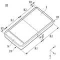
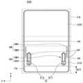
이들 도면에 도시한 바와 같이, 이동 단말기(100)는, 바디(BD)가 접히는 (foldable) 형태일 수 있다. 예를 들어, 바디(BD)의 일 끝단과 타 끝단이 근접 및/또는 상호 접촉하는 형태로 접히는 형태일 수 있음을 의미한다. 바디(BD)의 적어도 일측면에는 디스플레이(D)가 마련되어 있을 수 있다.As shown in these drawings, the
도 1에 도시한 바와 같이, 디스플레이(D)는, 바디(BD)의 적어도 일면의 실질적으로 전면(全面)에 형성되어 있을 수 있다. 이와 같은 점은, 종래의 폴더폰과는 다를 수 있다. 즉, 일면의 일부 영역에 디스플레이 영역이 존재하던 종래의 폴더폰과 달리, 본 발명의 일 실시예에 따른 이동 단말기(100)는 바디(BD)의 일 끝단과 타 끝단까지 하나의 디스플레이가 위치하고 있을 수 있음을 의미한다.As shown in Fig. 1, the display D may be formed substantially on the entire surface of at least one surface of the body BD. This may be different from the conventional folder phone. In other words, unlike the conventional folder phone in which the display area is present in a part of one surface, the
디스플레이(D)는, 플랙서블한 형태일 수 있다. 즉, 바디(BD)가 접히면, 그에 따라 디스플레이(D)도 접힐 수 있음을 의미한다. 이와 같은 점은, 종래의 디스플레이와 다른 특징일 수 있다. 플랙서블한 디스플레이(D)는, 바디(BD)의 적어도 어느 일면의 실질적으로 전(全)영역에 위치하고 있을 수 있다.The display D may be in a flexible form. That is, if the body BD is folded, it means that the display D can also be folded accordingly. This may be a different feature from the conventional display. The flexible display D may be located in substantially the entire area of at least one side of the body BD.
이동 단말기(100)는 일정한 두께를 가지고 있을 수 있다. 즉, Z 방향으로 T 만큼의 두께를 가지고 있을 수 있음을 의미한다. 이동 단말기(100)의 두께는, 바디(BD)와 디스플레이(D) 등을 포함하는 이동 단말기(100) 구성물의 Z 방향 합일 수 있다.The
이동 단말기는(100)는, 제1 상태(S1) 또는 제1 상태(S2)에 있을 수 있다.The
제1 상태(S1)는, 바디(BD)가 펴져있는 상태일 수 있다. 예를 들어, 바디(BD)가 복수의 영역으로 구분된다면, 복수의 영역으로 구분되는 바디(BD)가 동일 평면상에 배치된 상태가 제1 상태(S1)일 수 있다. 제1 상태(S1)에서, 이동 단말기(100)는 스틱 형태로 보여질 수 있다.The first state S1 may be a state in which the body BD is extended. For example, if the body BD is divided into a plurality of regions, a state in which the bodies BD divided into a plurality of regions are arranged on the same plane may be the first state S1. In the first state S1, the
제2 상태(S2)는, 바디(BD)가 구부러져 있는 상태일 수 있다. 예를 들어, 복수의 영역으로 구분된 바디(BD)의 어느 한 영역이 다른 영역에 폴드(fold)된 상태가 제2 상태(S2)일 수 있다. 제2 상태(S2)에서, 이동 단말기(100)의 길이는 약 절반으로 보여질 수 있다.The second state S2 may be a state in which the body BD is bent. For example, a state in which one region of a body BD divided into a plurality of regions is folded into another region may be a second state S2. In the second state S2, the length of the
제1 상태(S1)에서 제2 상태(S2)로 구부러지는 과정에서, 바디(BD)의 내측면과 외측면에는 길이차이가 발생할 수 있다. 길이차이는, 이동 단말기(100)의 두께 T로 인하여 발생할 수 있다. 즉, 두께 T로 인하여, 바디(BD)의 내측면까지의 반경인 제1 반경(R1)과 바디(BD)의 외측면까지의 반경인 제2 반경(R2) 간의 차이가 발생할 수 있다. 제1,2 반경(R1, R2)의 차이로 인하여, 바디(BD)가 접혀진 제2 상태에서 바디(BD) 내측면의 길이보다 바디(BD) 외측면의 길이가 길어지게 될 수 있다. 바디(BD) 내측면의 길이보다 바디(BD) 외측면의 길이가 길어지면, 바디(BD)를 접는 경우에 바디(BD) 내측면의 디스플레이(D)에 주름이 발생할 수 있다.In the process of bending from the first state S1 to the second state S2, a difference in length may occur between the inner side surface and the outer side surface of the body BD. The difference in length may occur due to the thickness T of the
제2 상태(S2)에서, 바디(BD) 내측면의 제1 반경(R1)은 필요할 수 있다. 이와 같은 점은, 바디(BD) 내측면에 위치한 디스플레이(D)가 납작하게 접혀지는 경우에 디스플레이(D)가 손상될 수 있다는 점을 고려할 때 명확히 이해될 수 있다. 따라서 이동 단말기(100)는, 제2 상태에서 바디 내측면의 제1 반경(R1)을 유지하기 위한 구조가 필요할 수 있다.In the second state S2, the first radius R1 of the inner side of the body BD may be required. This can be clearly understood in view of the fact that the display D positioned on the inner side of the body BD may be damaged when the display D is folded flat. Therefore, the
도 2의 (a)에 도시한 바와 같이, 이동 단말기(100)는, 제1 상태에 있을 때, 외력(F)에 저항할 수 있다. 예를 들어, Z 방향의 외력(F)이 가해지는 경우에도 변형되지 않고 제1 상태를 유지할 수 있음을 의미한다.As shown in Fig. 2A, the
도 2의 (b)에 도시한 바와 같이, 이동 단말기(100)는, 제2 상태에 있을 때, 외력(F)에 저항할 수 있다. 예를 들어, Z 방향의 외력(F)이 가해지는 경우에도 제1 반경(R1)이 유지될 수 있음을 의미한다. 제1 반경(R1)의 유지는, 전술한 바와 같이, 디스플레이(D)의 손상방지 등을 위하여 필요할 수 있다.As shown in Fig. 2 (b), the
도 2의 (c)에 도시한 바와 같이, 이동 단말기(100)는, 제2 상태에 있을 때 복수의 바디(BD)의 내측면이 상호 접촉되거나 밀접하게 위치될 수 있다. 이와 같은 점은, 제1 반경(R1)이 유지되는 경우와 다르다. 복수의 바디(BD)가 폴딩(folding)되어 상호 인접하여 위치되는 경우에, 디스플레이(D) 중 적어도 일부 영역은 회피영역(ES) 내로 이동될 수 있다. 따라서 제1 반경(R1)을 유지하지 않는 경우에도, 디스플레이(D)가 접히는 현상을 방지할 수 있다.As shown in Fig. 2 (c), when the
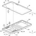
도 3 내지 도 15는, 본 발명의 일 실시예에 따른 이동 단말기 후면커버의 구성 및 동작을 설명하는 도면이다.FIGS. 3 to 15 are views illustrating the configuration and operation of the mobile terminal rear cover according to an embodiment of the present invention.
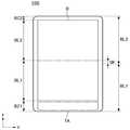
이들 도면에 도시한 바와 같이, 본 발명의 일 실시예에 따른 이동 단말기(100)는, 적어도 일부가 적어도 다른 일부에 대해 슬라이딩 이동될 수 있다. 예를 들어, 이동 단말기(100)의 후면커버(BC) 중 적어도 일부가 이동 단말기(100)의 바디(200)에 대해 슬라이딩 이동할 수 있음을 의미한다. 예를 들어, 이동 단말기(100)가 폴딩된 제2 상태에서도 후면커버(BC)가 슬라이딩 이동하여 디스플레이(D)의 일부가 노출될 수 있음을 의미한다.As shown in these drawings, the
도 3 및 도 4에 도시한 바와 같이, 이동 단말기(100)는 제1,2 바디(210, 220)가 실질적으로 동일 평면상에서 나란하게 위치한 제1 상태에 있을 수 있다.As shown in FIGS. 3 and 4, the
디스플레이(D)는, 제1,2 바디(210, 220)의 일면측에 위치하고 있을 수 있다. 예를 들어, 제1,2 바디(210, 220)가 폴딩되는 경우에 내측면이 되는 면에 위치하고 있을 수 있음을 의미한다. 예를 들어, 디스플레이(D)는, 제1,2 바디(210, 220) 상에 연속하여 위치하고 있을 수 있음을 의미한다.The display D may be positioned on one side of the first and
디스플레이(D)는, 제1,2 바디(210, 220)의 중심에서 오프셋(offset, OF)되도록 위치될 수 있다. 제1 바디(210)는 제1 바디길이(BL1)이고, 제2 바디(220)는 제2 바디길이(BL2)일 수 있다. 즉, 제1,2 바디(210, 220)를 연결하는 힌지어셈블리(미도시)를 중심으로 제1,2 바디길이(BL1, BL2)만큼 제1,2 바디(210, 220)가 형성되어 있을 수 있다.The display D may be positioned offset from the center of the first and
디스플레이(D)는, 디스플레이(D)의 중심을 기준으로 일측은 제1 디스플레이길이(DL1)이고 타측은 제2 디스플레이길이(DL2)일 수 있다. 디스플레이(D)의 중심은 제1,2 바디(210, 220)의 중심에서 오프셋(OF)되어 있을 수 있다.The display D may have a first display length DL1 on one side and a second display length DL2 on the other side with respect to the center of the display D. The center of the display D may be offset from the center of the first and
오프셋(OF)은, 디스플레이(D)의 위치로 인하여 발생될 수 있다. 즉, 디스플레이(D) 하측의 제1 베젤영역(BZ1)의 크기가 디스플레이(D) 상측의 제2 베젤영역(BZ2) 보다 큼으로 인하여, 디스플레이(D) 상대적으로 상측에 위치함으로 인하여 발생할 수 있음을 의미한다. 제1 베젤영역(BZ1)의 적어도 일부는, 투영영역(TA)일 수 있다.The offset (OF) can be caused by the position of the display (D). That is, it may occur due to the fact that the size of the first bezel area BZ1 on the lower side of the display D is larger than the second bezel area BZ2 on the upper side of the display D, . At least a part of the first bezel area BZ1 may be a projection area TA.
투영영역(TA)은, 실질적으로 투명 또는 반투명한 재질로 구성될 수 있다. 예를 들어, 디스플레이(D) 주위의 베젤 중 제1 베젤영역(BZ1)에 해당하는 부분의 투명도가 다른 부분보다 높을 수 있음을 의미한다. 예를 들어, 제1 베젤영역(BZ1)의 적어도 일부의 투명도가 그 외 영역과 다를 수 있음을 의미한다.The projection area TA may be composed of a material that is substantially transparent or translucent. For example, the transparency of the portion corresponding to the first bezel region BZ1 of the bezel around the display D may be higher than the other portions. For example, the transparency of at least a part of the first bezel region BZ1 may be different from that of the other region.
투영영역(TA)은, 이동 단말기(100)가 펼쳐진 제1 상태에서는 이를 통하여 후방이 관측될 수 없을 수 있다. 예를 들어, 제1 상태에서는 후면커버(BC)에 의하여 투영영역(TA)이 차폐될 수 있음을 의미한다. 투영영역(TA)은, 이동 단말기(100)가 접혀지는 도중 및/또는 접혀진 제2 상태에서는 이를 통해 후방이 관측될 수 있다.The projection area TA may not be observed rearward through the first state in which the
도 5 내지 도 7은, 본 발명의 일 실시예에 따른 이동 단말기(100)의 동작을 도시하고 있다. 이들 도면에 도시한 바와 같이, 본 발명의 일 실시예에 따른 이동 단말기(100)는, 제1 상태에서 제2 상태로 변화되면 투영영역(TA)을 통해 디스플레이(D)의 적어도 일부 영역을 관측할 수 있다.5 to 7 illustrate operations of the
도 5에 도시한 바와 같이, 디스플레이(D)는 제1,2 바디(210, 220)의 일측 면에 위치하고 후면커버(BC)는 제1,2 바디(210, 220)의 타측 면에 위치하고 있을 수 있다. 달리 표현하면, 제1,2 바디(210, 220)를 중심으로 디스플레이(D)와 후면커버(BC)가 각각 일면과 타면에 위치하고 있다고 볼 수 있다.5, the display D is positioned on one side of the first and
디스플레이(D)는, 전술한 바와 같이, 후면커버(BC)에 대해 오프셋(OF)되어 있을 수 있다. 달리 표현하면, 제1 베젤영역(BZ1)이 제2 베젤영역(BZ2) 보다 클 수 있다. 제1 베젤영역(BZ1)에는, 투영영역(TA)이 형성되어 있을 수 있다.The display D may be offset (OF) with respect to the rear cover BC, as described above. In other words, the first bezel area BZ1 may be larger than the second bezel area BZ2. In the first bezel area BZ1, a projection area TA may be formed.
이동 단말기(100)는, 제1 상태에 있을 수 있다. 즉, 제1,2 바디(210, 220)가 동일 평면 상에서 나란하게 위치하고 있을 수 있음을 의미한다.The
제1 상태에서, 이동 단말기(100)의 후면은 후면커버(BC)에 의하여 차폐되어(covered) 있을 수 있다. 달리 표현하면, 이동 단말기(100)의 후면이 후면커버(BC)에 의하여 가려져있는(veiled) 상태일 수 있음을 의미한다. 따라서 투영영역(TA)의 존재에 불구하고, 투영영역(TA)을 통해 전방에서 후방 또는 후방에서 전방이 관측될 수 없다.In the first state, the rear surface of the
도 6에 도시한 바와 같이, 이동 단말기(100)의 제1,2 바디(210, 220)가 굽혀진 상태에 있을 수 있다. 이와 같은 상태는, 제3 상태일 수 있다. 즉, 제1,2 바디(210, 220)가 완전히 펼쳐진 상태도 아니고, 제1,2 바디(210, 220)가 완전히 전혀진 상태도 아닌 상태에 있음을 의미한다.As shown in FIG. 6, the first and
제3 상태에서, 후면커버(BC)는 개구(OA)를 형성할 수 있다. 개구(OA)는, 전술한 바와 같이, 제1,2 바디(210, 220)의 두께로 인한 제1,2 바디(210, 220) 내측면과 외측면 사이의 이동거리의 차이에 의하여 발생될 수 있다.In the third state, the rear cover BC can form an opening OA. The opening OA is generated by a difference in moving distance between the inner side surface and the outer side surface of the first and
제3 상태에서, 개구(OA)는 제1 개구(OA1)를 형성할 수 있다. 즉, 후면커버(BC)의 제1 단부(BCT1)이 제1 바디(210) 후면에서 슬라이딩 이동하며 제1 바디(210)의 끝단에서 제1 개구(OA1) 만큼 이격될 수 있음을 의미한다. 후면커버(BC)의 슬라이딩 이동으로 제1 개구(OA1)가 발생하면, 제1 개구(OA1)와 투영영역(TA)이 오버랩(overlap)되는 영역이 발생될 수 있다. 제1 개구(OA1)와 투영영역(TA)이 오버랩되면, 오버랩 영역을 통해 전방에서 후방 또는 후방에서 전방이 관측될 수 있다.In the third state, the aperture OA can form the first aperture OA1. That is, the first end BCT1 of the rear cover BC may slide at the rear of the
제3 상태에서, 디스플레이(D)의 적어도 일부 영역은 회피영역(ES)으로 이동될 수 있다. 즉, 제1,2 바디(210, 220)의 두께로 인한 제1,2 바디(210, 220) 외측면의 제1 개구(OA1) 형성과 함께, 제1,2 바디(210, 220) 내측면의 디스플레이(D)의 일부가 회피영역(ES)으로 밴딩될 수 있음을 의미한다. 회피영역(ES)으로의 밴딩은, 해당하는 부분에서 구체적으로 설명하도록 한다.In the third state, at least some of the areas of the display D can be moved to the avoiding area ES. That is, the first opening OA1 is formed on the outer surfaces of the first and
도 7에 도시한 바와 같이, 이동 단말기(100)는 제2 상태에 있을 수 있다. 즉, 제1,2 바디(210, 220)가 완전히 폴딩된 상태에 있을 수 있음을 의미한다. 달리 표현하면, 제1,2 바디(210, 220) 끝단 영역의 적어도 일부가 상호 접촉된 상태에 있을 수 있ㅇ므을 의미한다.As shown in Fig. 7, the
제2 상태에서, 개구(OA)는 제2 개구(OA2)를 형성할 수 있다. 제2 개구(OA2)는 제1 개구(OA1) 보다 클 수 있다. 즉, 제1,2 바디(210, 220)가 완전히 폴딩됨으로 인하여, 개구(OA)의 크기가 최대화될 수 있음을 의미한다.In the second state, the aperture OA can form the second aperture OA2. The second opening OA2 may be larger than the first opening OA1. That is, the first and
제2 개구(OA2)는, 면적이 투영영역(TA)의 면적과 실질적으로 동일할 수 있다. 또는, 제2 개구(OA2) 영역의 전부가 투영영역(TA)과 오버랩될 수 있다.The area of the second opening OA2 may be substantially equal to the area of the projection area TA. Alternatively, the entire area of the second aperture OA2 may overlap with the projection area TA.
제2 개구(OA2)로 인하여, 디스플레이(D)의 외부에서 관측될 수 있다. 즉, 제1,2 바디(210, 220)가 완전히 폴딩된 제2 상태임에도 불구하고 제1,2 바디(210, 220) 내측에 위치하고 있는 디스플레이(D)의 일부 영역에 표시된 영상을 관측할 수 있음을 의미한다. 예를 들어, 디스플레이(D)의 활성화영역(AD)에 표시된 영상을 시각적으로 관측할 수 있음을 의미한다.Can be observed from the outside of the display (D) due to the second opening (OA2). That is, even though the first and
제어부(도 28의 180)는, 제2 상태에 있을 때 디스플레이(D)의 활성화영역(AD)에만 영상을 표시할 수 있다. 제어부(도 28의 180)는 제2 상태에 있을 때 제2 개구(OA2)에 대응된 활성화영역(AD)에만 영상을 표시할 수 있다. 제어부(도 28의 180)는, 제2 상태에 있을 때 디스플레이(D)의 다른 부분은 비활성화 시키고 제2 개구(OA2)에 대응된 부분은 활성화 시킬 수 있다.The
도 8 내지 도 11은, 본 발명의 일 실시예에 따른 이동 단말기(100)의 후면커버(BC) 슬라이딩 구조를 도시한 도면이다.8 to 11 are views showing a rear cover (BC) sliding structure of the
도 8에 도시한 바와 같이, 바디(200)는, 제1,2 바디(210, 220)를 포함할 수 있다. 제1 바디(210)의 일측에는 투영영역(TA)이 존재할 수 있다.As shown in FIG. 8, the
후면커버(BC)는, 바디(200)의 후면측에 위치하고 있을 수 있다.The rear cover BC may be located on the rear side of the
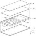
디스플레이(D)는, 바디(200)의 전면측에 위치하고 있을 수 있다.The display D may be located on the front side of the
플레이트(DB)는, 디스플레이(D)와 바디(200)의 사이에 위치하고 있을 수 있다. 플레이트(DB)는, 디스플레이(D)를 지지할 수 있다. 플레이트(DB)는, 복수의 영역을 포함할 수 있다. 복수의 영역을 포함하는 플레이트(DB)는, 이동 단말기(100)가 제1 상태에 있는 경우에는 디스플레이(D)를 지지하면서도 이동 단말기(100)의 폴딩을 방해하지 않을 수 있다. 플레이트(DB)의 구체적은 구성은 해당하는 부분에서 설명하도록 한다.The plate DB may be positioned between the display D and the
도 9에 도시한 바와 같이, 바디(200)의 후면에는 후면커버(BC)의 슬라이딩을 위한 구조가 존재할 수 있다.As shown in FIG. 9, a structure for sliding the rear cover BC may exist on the rear surface of the
바디(200)에는, 이동 단말기(100)의 동작에 필요한 각종 부품이 내장될 수 있다. 바디(200)는, 후면커버(BC)의 적어도 일부분이 고정된 제2 바디(220)와, 후면커버(BC)의 슬라이딩 동작이 발생하는 제1 바디(210)를 포함할 수 있다. 제1 바디(210)에는, 이동 단말기(100)의 제어부(180)가 실장된 PCB(PCB)가 위치할 수 있다. 제2 바디(220)에는, 베터리(BT)가 위치하고 있을 수 있다. 제1,2 바디(210, 220) 간에는 플랙서블케이블(FP)이 연결되어 있을 수 있다. 제1,2 바디(210, 220)는 힌지어셈블리(HGA)에 의하여 상호 회전가능하도록 연결되어 있을 수 있다. 제1 바디(210)에는, 슬라이더(SH)와, 슬라이딩마그넷(SM)이 위치하고 있을 수 있다.Various components necessary for the operation of the
슬라이더(SH)는, 후면커버(BC)에 결합될 수 있다. 이동 단말기(100)의 원활한 폴딩동작을 위하여, 후면커버(BC)는 폴딩된 정도에 비례하여 슬라이딩 되어야 한다. 후면커버(BC)가 슬라이더(SH)에 결합됨으로 인하여, 슬라이더(SH)는 슬라이딩 되는 후먼커버(BC)의 운동에너지를 저장할 수 있다. 따라서 이동 단말기(100)가 다시 제1 상태로 되돌아갈 때 슬라이더(SH)에 저장되었던 에너지로 인하여 후면커버(BC)가 최초위치로 되돌아갈 수 있다.The slider SH can be coupled to the rear cover BC. For smooth folding operation of the
슬라이딩마그넷(SM)은, 슬라이더(SH)에 인접한 영역에 위치할 수 있다. 예를 들어, 슬라이딩마그넷(SM)의 적어도 일부가 슬라이더(SH)와 가로방향(x 방향)으로 오버랩될 수 있음을 의미한다.The sliding magnet SM may be located in an area adjacent to the slider SH. For example, this means that at least a part of the sliding magnet SM can overlap with the slider SH in the lateral direction (x direction).
슬라이딩마그넷(SM)은, 후면커버(BC)의 들뜸을 방지할 수 있다. 전술한 바와 같이, 후면커버(BC)는 슬라이더(SH)에 결합될 수 있다. 다만, 후면커버(BC)와 슬라이더(SH) 간의 결합은 제한된 특정 지점에 한정될 수 있다. 슬라이딩마그넷(SM)은, 길이방향(y방향)으로 후면커버(BC)의 내측면에 부착될 수 있다. 후면커버(BC)에는 슬라이딩마그넷(SM)에 대응된 마그넷영역(도 12의 M)이 마련되어 있을 수 있다. 슬라이딩마그넷(SM)과 접촉영역(도 12의 M)이 상호간의 자력에 의하여 후면커버(BC)가 바디(200)에 밀착될 수 있다. 즉, 슬라이딩마그넷(SM)이 접촉영역(도 12의 M)에 자성결합(magnetically attached)할 수 있음을 의미한다.The sliding magnet SM can prevent lifting of the rear cover BC. As described above, the rear cover BC can be coupled to the slider SH. However, the coupling between the rear cover BC and the slider SH may be limited to a specific limited point. The sliding magnet SM can be attached to the inner surface of the rear cover BC in the longitudinal direction (y direction). The rear cover BC may be provided with a magnet region (M in Fig. 12) corresponding to the sliding magnet SM. The rear cover BC can be brought into close contact with the
도 10에 도시한 바와 같이, 바디(200)는, 복수의 영역으로 구분될 수 있다. 예를 들어, 고정영역(FA)과, 폴딩영역(CA)과, 슬라이딩영역(SA)을 포함할 수 있음을 의미한다.As shown in Fig. 10, the
고정영역(FA)은, 제2 바디(220) 상에 마련될 수 있다. 후면커버(BC) 중 적어도 일부영역은, 고정영역(FA)에 결합될 수 있다.The fixed area FA may be provided on the
폴딩영역(CA)은, 힌지어셈블리(도 9의 HGA)에 의하여 제1,2 바디(210, 220)가 상대운동하는 영역일 수 있다.The folding area CA may be a region where the first and
슬라이딩영역(SA)은, 후면커버(BC)가 제1 바디(210)에 대해 상대운동하는 영역일 수 있다. 슬라이딩영역(SA)에는, 슬라이더(SH)와 슬라이딩마그넷(SM)이 위치하고 있을 수 있다.The sliding region SA may be a region in which the rear cover BC is moved relative to the
도 11에 도시한 바와 같이, 후면커버(BC)의 내측에는 결합돌기(B)가 마련되어 있을 수 있다. 결합돌기(B)는, 슬라이더(SH)의 삽입구(IF)에 결합될 수 있다. 삽입구(IF)는 스프링(SP)에 의하여 지지되고 있을 수 있다.As shown in Fig. 11, the engaging projection B may be provided on the inner side of the rear cover BC. The engaging projection B can be engaged with the insertion port IF of the slider SH. The insertion port IF may be supported by a spring SP.
도 12에 도시한 바와 같이, 제1,2 바디(210, 220)가 나란하게 위치한 제1 상태에 있을 수 있다. 제1 상태에서, 후면커버(BC)의 제1,2 결합돌기(B1, B2)는 제1,2 삽입구(IF1, IF2)에 각각 결합되어 있을 수 있다. 제1 상태에서, 제1,2 삽입구(IF1, IF2)는 슬라이더(SH)의 말단에서 초기거리(IP) 이격되어 있을 수 있다.As shown in FIG. 12, the first and
도 13에 도시한 바와 같이, 제1,2 바디(210, 220)는 제3 상태에 있을 수 있다. 제3 상태에서 후면커버(BC)는 y 방향으로 일정거리 이동된 상태일 수 있다. 즉, 초기거리(IP)에서 이동거리(MP)의 상태로 y 방향으로 이동한 상태일 수 있음을 의미한다. 초기거리(IP)의 크기는 이동거리(MP)의 크기보다 클 수 있다.As shown in FIG. 13, the first and
제1,2 슬라이딩마그넷(SM1, SM2)은, 후면커버(BC)가 일정거리 슬라이딩 이동하는 중에도 제1,2 접촉영역(M1, M2)과의 접촉이 유지될 수 있다. 즉, 제1,2 스라이딩마그넷(SM1, SM2)와 제1,2 접촉영역(M1, M2) 사이 자력의 정도에가 적절히 조절되면, 양 구성이 이격되지 않으면서도 후면커버(BC)의 슬라이딩이 이루어질 수 있음을 의미한다. 제1,2 접촉영역(M1, M2)은, 금속 및/또는 자성체일 수 있다.The first and second sliding magnets SM1 and SM2 can maintain contact with the first and second contact areas M1 and M2 even while the rear cover BC is slidingly moved by a predetermined distance. That is, if the degree of the magnetic force between the first and second sliding magnets SM1 and SM2 and the first and second contact areas M1 and M2 is appropriately adjusted, the sliding of the rear cover BC Can be achieved. The first and second contact areas M1 and M2 may be metal and / or magnetic materials.
도 14의 (a)에 도시한 바와 같이, 이동 단말기(100)는 제1 상태에 있을 수 있다.As shown in Fig. 14 (a), the
도 14의 (b)에 도시한 바와 같이, 이동 단말기(100)는 폴딩된 제2 상태에 있을 수 있다. 제2 상태가 되면, 후면커버(BC)의 일부가 슬라이딩 되며 투영영역(TA)을 통해 디스플레이영역(AD)이 노출될 수 있다. 즉, 디스플레이(D) 전체 중 일부 영역이 외부로 노출될 수 있음을 의미한다. 따라서 제2 상태에 있는 이동 단말기(100)를 언폴딩(unfolding) 하는 등의 추가적인 조작을 가하지 않는 경우에도 사용자에게 필요한 시각정보를 전달할 수 있다.As shown in FIG. 14 (b), the
도 15의 (a)에 도시한 바와 같이, 본 발명의 다른 실시예에 따른 이동 단말기(100)는 카메라(121)를 포함하고 있을 수 있다. 카메라(121)는, 디스플레이(D)의 리세스(recess) 영역(RC)에 위치하고 있을 수 있다. 즉, 사각형의 디스플레이(D)의 일부 영역이 절개된 형태의 리세스 영역(RC)이 존재할 수 있음을 의미한다. 이와 같은 형태는, 베젤영역에서 카메라(121)를 실장할만한 공간의 확보가 용이하지 않은 경우에 유용할 수 있다.As shown in FIG. 15 (a), the
도 15의 (b)에 도시한 바와 같이, 리세스 영역(RC)의 카메라(121)는, 이동 단말기(100)가 제2 상태에 있는 경우에도 외부를 촬영할 수 있다. 즉, 투영영역(TA)을 통해 카메라(121)가 외부로 노출될 수 있음을 의미한다. 달리 표현하면, 투영영역(TA)을 통해 카메라(121)와 디스플레이영역(AD)이 동시에 노출될 수 있음을 의미한다.The
도 16 내지 도 18은, 본 발명의 일 실시예에 따른 이동 단말기의 동작을 도시한 도면이다.16 to 18 are diagrams illustrating operations of a mobile terminal according to an embodiment of the present invention.
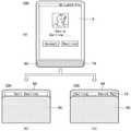
이들 도면에 도시한 바와 같이, 본 발명의 일 실시예에 따른 이동 단말기(100)의 제어부(180)는, 이동 단말기(100)의 폴딩상태에 따라 서로 다른 동작을 수행할 수 있다.As shown in these drawings, the
도 16에 도시한 바와 같이, 제어부(180)는, 이동 단말기(100)의 상태를 판단할 수 있다.As shown in FIG. 16, the
제어부(180)는, 이동 단말기(100)가 제1 상태에 있는 경우(S10)에, 디스플레이(D) 전 영역을 활성화할 수 있다.(S20) 달리 표혐하면, 디스플레이(D)의 전체 영역을 사용하여 영상을 표시할 수 있음을 의미한다.The
제어부(180)는, 이동 단말기(100)가 제2 상태에 있는 경우(S30)에, 디스플레이(D) 일부 영역을 활성화할 수 있다.(S40) 달리 표현하면, 디스플레이(D)의 일부 영역은 활성화하고 다른 영역은 비활성화할 수 있음을 의미한다.The
도 17의 (a)에 도시한 바와 같이, 제2 상태에서 제어부(180)는 디스플레이영역(AD)에 특정 정보를 표시할 수 있다. 예를 들어, 디스플레이영역(AD)에 시각 정보를 표시할 수 있다. 사용자는 이동 단말기(100)가 접혀진 상태에서도 시각 정보를 확인할 수 있다.As shown in Fig. 17A, in the second state, the
제어부(180)는, 후면커버(BC)에 의하여 가려진 차폐영역(DAD)은 비활성화할 수 있다. 즉, 외부로 노출되는 최소한의 영역만 선택적으로 활성화하여 정보를 표시할 수 있음을 의미한다. 따라서 이동 단말기(100)의 동작에 필요한 소모전류를 최소화할 수 있다.The
도 17의 (b)에 도시한 바와 같이, 제2 상태에서 제어부(180)는 디스플레이영역(AD)에 이벤트 정보를 표시할 수 있다. 예를 들어, 메시지의 수신 여부, 수신한 메시지의 내용을 표시할 수 있음을 의미한다. 이벤트 정보는, 시각 정보 등 다른 정보와 함께 표시될 수 있다.As shown in Fig. 17B, in the second state, the
도 18에 도시한 바와 같이, 제어부(180)는 이동 단말기(100)에 대한 사용자의 조작에 따라 특정한 동작을 수행할 수 있다.As shown in FIG. 18, the
도 18의 (a)에 도시한 바와 같이, 이동 단말기(100)는 제1 상태에서 콜(call)을 수신하고 있을 수 있다. 제어부(180)는, 콜의 수신상황을 디스플레이(D)에 표시할 수 있다.As shown in FIG. 18 (a), the
도 18의 (b)에 도시한 바와 같이, 콜의 수신 중에 사용자는 이동 단말기(100)를 제1 상태에서 제2 상태로 전환할 수 있다. 즉, 펼쳐져 있던 이동 단말기(100)를 접는 동작을 수행할 수 있음을 의미한다. 이동 단말기(100)를 제2 상태로 변환하면, 제어부(180)는 사용자가 콜의 수신을 거절하는 것으로 판단할 수 있다. 따라서 제어부(180)는 관련 내용을 디스플레이영역(AD)에 표시하고 콜의 수신을 중단할 수 있다.As shown in FIG. 18 (b), the user can switch the mobile terminal 100 from the first state to the second state during reception of the call. That is, it means that the folded
도 18의 (c)에 도시한 바와 같이, 콜의 수신 중에 사용자가 이동 단말기(100)를 제1 상태에서 제2 상태로 전환하면, 제어부(180)는 콜의 수신을 알리는 화면을 전환할 수 있다. 즉, 제1 상태에서 디스플레이(D)의 전체 영역에 표시하던 콜수신 알림 화면을, 제2 상태에서는 디스플레이영역(AD)에 대응되도록 표시할 수 있음을 의미한다.As shown in (c) of FIG. 18, when the user switches the mobile terminal 100 from the first state to the second state during reception of the call, the
제어부(180)는, 디스플레이영역(AD)에 콜 수신상태 및/또는 콜 수신여부에 대한 사용자의 터치입력을 유도하는 아이콘(IC)을 표시할 수 있다. 디스플레이영역(AD)에 대한 터치입력을 획득하도록, 투영영역(TA)에는 터치센서가 내장될 수 있다. 제어부(180)는 투영영역(TA)에 내장된 터치센서를 이동 단말기(100)가 제2 상태에 있을 때 선택적으로 활성화할 수 있다.The
도 19 내지 도 22는, 본 발명의 일 실시예에 따른 이동 단말기의 힌지어셈블리의 구성 및 동작을 설명하는 도면이다.19 to 22 are views illustrating the configuration and operation of a hinge assembly of a mobile terminal according to an embodiment of the present invention.
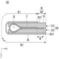
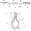
이들 도면에 도시한 바와 같이, 본 발명의 일 실시예에 따른 이동 단말기(100)의 힌지어셈블리(HGA)는, 이동 단말기(100)의 상태변화에 따른 디스플레이(D)의 위치변화를 가이드할 수 있다. 본 발명의 일 실시예에 따른 이동 단말기(100)의 힌지어셈블리(HGA)는, 위치가 변화된 디스플레이(D)를 수용할 공간을 제공할 수 있다.As shown in these drawings, the hinge assembly (HGA) of the
도 19에 도시한 바와 같이, 힌지어셈블리(HGA)는 이동 단말기(100)의 제1,2 바디(210, 220)를 연결할 수 있다. 힌지어셈블리(HGA)를 중심으로 제1,2 바디(210, 220)는 회전할 수 있다.As shown in FIG. 19, the hinge assembly (HGA) can connect the first and
힌지어셈블리(HGA)는, 가이드샤프트(SFT)와 헤드(H)를 포함할 수 있다. 해드(H)와 가이드샤프트(SFT)는, 힌지축(HS)으로 연결될 수 있다. 가이드샤프트(SFT)는, 일측이 힌지축(HS)과 연결되고 타측은 바디(200)에 연결될 수 있다. 즉, 제1 가이드샤프트(SFT1)는 제1 헤드(H1) 및 제1 바디(210)에 연결되고, 제2 가이드샤프트(SFT2)는 제2 헤드(H2) 및 제2 바디(220)에 연결될 수 있음을 의미한다.The hinge assembly (HGA) may include a guide shaft (SFT) and a head (H). The head H and the guide shaft SFT may be connected by a hinge axis HS. One side of the guide shaft SFT may be connected to the hinge axis HS and the other side thereof may be connected to the
가이드샤프트(SFT)의 길이는, 디스플레이(D)의 폭(W)과 실질적으로 동일하거나 길수 있다. 즉, 가이드샤프트(SFT)가 그에 대응된 디스플레이(D) 영역 전체를 가이드할 수 있음을 의미한다.The length of the guide shaft (SFT) may be substantially equal to or longer than the width (W) of the display (D). That is, it means that the guide shaft SFT can guide the entire area of the display D corresponding thereto.
도 20에 도시한 바와 같이, 가이드샤프트(SFT)는 복수 개가 상호 대칭된 형태로 배치될 수 있다. 복수의 가이드샤프트(SFT)는, 이동 단말기(100)의 상태변화에 관계없이 서로 대칭된 형태를 유지할 수 있다.As shown in Fig. 20, a plurality of guide shafts (SFTs) may be arranged in mutually symmetrical form. The plurality of guide shafts (SFTs) can maintain symmetry with each other regardless of the state change of the
가이드샤프트(SFT)는, 회피영역(ES)을 형성할 수 있다. 즉, 상태변화에 따라 디스플레이(D)의 일부 영역이 이동될 수 있는 영역이 존재함을 의미한다.The guide shaft (SFT) can form the avoidance area ES. That is, there is a region in which a part of the display D can be moved according to the state change.
회피영역(ES)은, 가이드샤프트(SFT)의 형상에 의하여 마련될 수 있다. 예를 들어, 회피영역(ES)은 복수의 곡선부(CV1, CV2, CV3)에 의하여 형성될 수 있음을 의미한다. 가이드샤프트(SFT)가 헤드(H)에 연결되는 지점을 중심으로 가장 멀리 위치한 지점에 제1 곡선부(CV1)가 위치하고, 제2,3 곡선부(CV2, CV3)가 순차적으로 헤드(H)에 근접될 수 있다. 달리 표현하면, 복수의 곡선부(CV1, CV2, CV3) 중 적어도 일부가 이동 단말기(100)의 폭 방향으로 헤드(H) 중 적어도 일부 영역과 오버랩 된다고 할 수 있다. 달리 표현하면, 복수의 곡선부(CV1, CV2, CV3)는 제1,2 바디(210, 220)가 상호 인접한 영역에 형성되어 있다고 할 수 있다. 달리 표현하면, 복수의 곡선부(CV1, CV2, CV3)는 이동 단말기(100)의 폴딩이 발생하는 영역에 근접하여 위치하고 있다고 할 수 있다.The avoidance area ES can be provided by the shape of the guide shaft (SFT). For example, the avoidance area ES may be formed by a plurality of curved portions CV1, CV2, and CV3. The first curved portion CV1 is positioned at the furthest point around the point where the guide shaft SFT is connected to the head H and the second and third curved portions CV2 and CV3 are sequentially positioned on the head H, Lt; / RTI > In other words, it can be said that at least a part of the plurality of curved portions CV1, CV2, and CV3 overlaps at least a part of the head H in the width direction of the
곡선부(CV1, CV2, CV3)는, 서로 다른 곡률을 가지고 있을 수 있다. 예를 들어, 제1 곡선부(CV1)의 곡률은, 제3 곡선부(CV3)의 곡률 보다 클 수 있다. 제2 곡선부(CV2)의 곡률은, 제1,3 곡선부(CV1, CV3)의 곡률보다 클 수 있다.The curved portions CV1, CV2, and CV3 may have different curvatures. For example, the curvature of the first curved portion CV1 may be larger than that of the third curved portion CV3. The curvature of the second curved portion CV2 may be larger than that of the first and third curved portions CV1 and CV3.
도 21의 (a)에 도시한 바와 같이, 제1 상태에서 디스플레이(D)는 제1,2 바디(210, 220)의 상면에 평탄하게 위치하고 있을 수 있다.As shown in FIG. 21 (a), in the first state, the display D may be flat on the upper surfaces of the first and
도 21의 (b)에 도시한 바와 같이, 제1,2 바디(210, 220)가 접히기 시작하면, 디스프레이(D)의 밴딩영역(BA)은 회피영역(ES)으로 이동하기 시작한다. 제1 곡선부(CV1)은, 디스플레이(D)의 회피영역(ES)으로의 이동을 가이드할 수 있다. 즉, 제1 곡선부(CV1)의 곡선면에 디스플레이(D)의 밴딩영역(BA)이 접촉되며 디스플레이(D)의 밴딩이 자연스럽게 이루어질 수 있음을 의미한다.As shown in FIG. 21 (b), when the first and
제1,2 바디(210, 220)의 접힘정도에 따라, 밴딩영역(BA)은, 제2, 3 곡선부(CV2, CV3)에서 순차적으로 접할 수 있다. 제2,3 곡선부(CV2, CV3)에 접하며 디스플레이(D)는 자연스럽게 회피영역(ES) 내로 위치될 수 있다.Depending on the degree of folding of the first and
도 22에 도시한 바와 같이, 제2 상태에서 디스플레이(D)의 밴딩영역(BA)은, 제1 내지 3 곡선부(CV1, CV2, CV3) 중 적어도 한 부분에 접하고 있을 수 있다. 제1 내지 3 곡선부(CV1, CV2, CV3)에 접하는 밴딩영역(BA)은, 안정적으로 회피영역(ES)에 위치될 수 있다.As shown in Fig. 22, the banding area BA of the display D in the second state may be in contact with at least one of the first to third curved portions CV1, CV2, and CV3. The bending areas BA contacting the first to third curved parts CV1, CV2, and CV3 can be stably positioned in the avoiding area ES.
도 23은, 본 발명의 일 실시예에 따른 이동 단말기의 플레이트 구성을 설명하는 도면이다.23 is a view for explaining a plate configuration of a mobile terminal according to an embodiment of the present invention.
이에 도시한 바와 같이, 본 발명의 일 실시예에 따른 이동 단말기(100)의 플레이트(DB)는, 디스플레이(D)를 지지할 수 있다.As shown, a plate (DB) of the
플레이트(DB)는, 디스플레이(D)와 바디(200)의 사이에 위치하고 있을 수 있다. 플레이트(DB)는, 디스플레이(D)를 지지할 수 있다. 예를 들어, 제1 상태에서 플랙서블한 디스플레이(D)가 평탄한 형태를 유지하도록 할 수 있음을 의미한다.The plate DB may be positioned between the display D and the
플레이트(DB)는, 복수의 영역으로 구성될 수 있다. 예를 들어, 리지드(rigid)영역(SS1, SS2)과 플랙서블영역(SI)을 포함할 수 있음을 의미한다. 플랙서블 영역(SI)은, 디스플레이(D)의 밴딩영역(BA)에 대응될 수 있다.The plate (DB) can be composed of a plurality of regions. For example, it may include rigid regions SS1 and SS2 and flexible region SI. The flexible area SI can correspond to the banding area BA of the display D.
리지드영역(SS1, SS2)은, 경질재질로 구성될 수 있다. 예를 들어, 서스(SUS) 및/또는 플라스틱 재질일 수 있음을 의미한다. 플랙서블영역(SI)은, 연질재질로 구성될 수 있다. 예를 들어, 실리콘 재질일 수 있음을 의미한다. 따라서 디스플레이(D)를 효과적으로 지지하면서도 밴딩이 가능할 수 있다.The rigid regions SS1 and SS2 may be made of a hard material. For example, SUS and / or plastic material. The flexible area SI may be made of a soft material. For example, it may be a silicon material. Thus, the display D can be effectively supported while being bent.
도 24는, 본 발명의 일 실시예에 따른 플랙서블케이블의 구성을 설명하는 도면이다.24 is a view for explaining a configuration of a flexible cable according to an embodiment of the present invention.
이에 도시한 바와 같이, 본 발명의 일 실시예에 따른 이동 단말기(100)는 제1,2 바디(210, 220)의 폴딩에 따른 길이 변화에 대응할 수 있는 플랙서블케이블(FP)을 포함할 수 있다.As shown, the
도 24의 (a)에 도시한 바와 같이, 플랙서블케이블(FP)은, 제1,2 바디(210, 220)에 걸쳐 위치하고 있을 수 있다. 즉, 제1 바디(210)에 내장된 전자부품과 제2 바디(220)에 내장된 전자부품 간의 신호를 플랙서블케이블(FP)을 통해 전달할 수 있음을 의미한다. 플랙서블케이블(FP)에는 코일영역(FPCA)이 형성되어 있을 수 있다.As shown in FIG. 24 (a), the flexible cable FP may be positioned over the first and
코일영역(FPCA)은, 플랙서블케이블(FP)의 경로상에 형성되어 있을 수 있다. 코일영역(FPCA)은, 플랙서블케이블(FP)이 중첩되어 있는 영역일 수 있다. 코일영역(FPCA)는, 후면커버(BC)가 고정되어 있는 제2 바디(220)에 위치하고 있을 수 있다.The coil region FPCA may be formed on the path of the flexible cable FP. The coil region FPCA may be an area in which the flexible cables FP are overlapped. The coil area FPCA may be located in the
코일영역(FPCA)은, 제1,2 바디(210, 220)의 폴딩 및 언폴딩에 따른 길이변화를 완충할 수 있다. 예를 들어, 이동 단말기(100)가 제1 상태에 있을 때 코일영역(FPCA)에 중첩된 플랙서블케이블(FP)의 길이가 가장 길 수 있다.The coil region FPCA can buffer a change in length due to the folding and unfolding of the first and
도 24의 (b)에 도시한 바와 같이, 이동 단말기(100)가 완전히 폴딩된 제2 상태가 되면 코일영역(FPCA)에 중첩된 플랙서블케이블(FP)의 길이가 가장 짧거나 코일영역(FPCA)이 일시적으로 사라질 수 있다. 즉, 코일영역(FPCA)이 풀리며 제1,2 바디(210, 220)의 폴딩에 따른 길이변화를 보상할 수 있음을 의미한다.24 (b), when the
도 25 내지 도 29는, 본 발명의 일 실시예에 따른 이동 단말기에 내장된 자석어셈블리의 구성 및 동작을 설명하는 도면이다.25 to 29 are views illustrating the configuration and operation of a magnet assembly built in a mobile terminal according to an embodiment of the present invention.
이들 도면에 도시한 바와 같이, 본 발명의 일 실시예에 따른 이동 단말기(100)는 복수의 자석어셈블리(SM, HM)을 포함하고 있을 수 있다. 복수의 자석(SM, HM)은, 이동 단말기(100)가 특정 위치에 안정적으로 고정되도록 할 수 있다.As shown in these drawings, the
도 25에 도시한 바와 같이, 이동 단말기(100)에는 제1,2 자석어셈블리(SM, HM)이 위치하고 있을 수 있다. 제1 자석어셈블리(SM)는, 디스플레이(D) 측면의 베젤에 위치하고 있을 수 있다. 제2 자석어셈블리(HM)는, 제1,2 바디(210, 220)의 엣지영역에 위치하고 있을 수 있다. 이해의 편의를 위하여 자석어셈블리(SM, HM)를 이동 단말기(100) 각 부분에 도시하였으나, 자석어셈블리(SM, HM)는 이동 단말기(100) 내부에 내장되어 있을 수 있다. 따라서 자석어셈블리(SM, HM)를 외부에서 시각으로 관측할 수 있는 것은 아닐 수 있다.As shown in FIG. 25, the first and second magnet assemblies SM and HM may be located in the
제1 자석어셈블리(SM)는, 제1a 내지 1d 자석어셈블리(SM1 내지 SM4)를 포함할 수 있다. 제1a 자석어셈블리(SM1)와 1c 자석어셈블리(SM3)는 상호 대응되도록 위치하고 있을 수 있다. 제1b 자석어셈블리(SM2)와 제1d 자석어셈블리(SM4)는 상호 대응되도록 위치하고 있을 수 있다. 즉, 이동 단말기(100)가 폴딩되면 상호 근접되도록 배치되어 있을 수 있음을 의미한다.The first magnet assembly SM may include first to ld magnet assemblies SMl to SM4. The 1a magnet assembly SM1 and the 1c magnet assembly SM3 may be positioned so as to correspond to each other. The first b magnet assembly SM2 and the first d magnet assembly SM4 may be positioned so as to correspond to each other. That is, when the
제2 자석어셈블리(HM)는, 제2a 내지 2d 자석어셈블리(HM1 내지 HM4)를 포함할 수 있다. 제2a 내지 2d 자석어셈블리(HM1 내지 HM4)는, 제1,2 바디(210, 220)이 접하는 모서리 영역에 배치되어 있을 수 있다. 따라서 이동 단말기(100)가 제1 상태에 있을 때, 대응된 제2 자석어셈블리(HM)가 서로 근접될 수 있다. 제2 자석어셈블리(HM)가 서로 근접되면, 제1,2 바디(210, 220)는 상호 접촉될 수 있다. 따라서 다소간의 외력이 가해지는 경우에도 제1,2 바디(210, 220)의 펼쳐진 상태가 유지될 수 있다.The second magnet assembly HM may include the second to second magnet assemblies HM1 to HM4. The magnet assemblies HM1 to HM4 may be disposed in corner areas where the first and
도 26에 도시한 바와 같이, 제2 상태인 경우에 제1 자석어셈블리(SM)가 상호 근접될 수 있다. 예를 들어, 제1 바디(210)의 제1c 자석어셈블리(SM3)와 제2 바디(220)의 제1a 자석어셈블리(SM1)가 근접될 수 있음을 의미한다. 제1c 자석에셈블리(SM3)와 제1a 자석어셈블리(SM1)은 상호간에 인력이 작용하고 있을 수 있다. 따라서 제1,2 바디(210, 220)는 제1 자석어셈블리(SM)의 자력을 넘어서는 외력이 가해지기 전에는 이격되지 않을 수 있다. 즉, 제2 상태를 안정적으로 유지할 수 있음을 의미한다.As shown in Fig. 26, in the case of the second state, the first magnet assemblies SM can be brought close to each other. For example, the first c-magnet assembly SM3 of the
도 27에 도시한 바와 같이, 제1 상태인 경우에 제2 자석어셈블리(HM)가 상호 근접될 수 있다. 예를 들어, 제1 바디(210)의 측면에 배치된 제2a 자석어셈블리(HM1)와 제2 바디(220)의 측면에 배치된 제2b 자석어셈블리(HM2)가 제1 상태가 되면 상호 근접될 수 있음을 의미한다. 제2a 자석어셈블리(HM1)과 제2b 자석어셈블리(HM2)는 상호 인력이 작용하고 있을 수 있다. 따라서 제1,2 바디(210, 220)는 제2 자석어셈블리(HM)의 자력을 넘어서는 외력이 가해지기 전에는 제1 상태를 유지할 수 있다. 따라서 디스플레이(D)에 대한 사용자의 터치동작 등을 보다 안정적으로 수행할 수 있다.As shown in Fig. 27, in the first state, the second magnet assemblies HM can be brought close to each other. For example, when the second magnet assembly HM1 disposed on the side surface of the
도 28에 도시한 바와 같이, 본 발명의 일 실시예에 따른 자석어셈블리(SM, HM)은 복수의 자석(MA)의 조합일 수 있다. 자석(MA)은 제1, 2, 3 자석(MA1, MA2, MA3)를 포함할 수 있다.As shown in FIG. 28, the magnet assemblies SM and HM according to an embodiment of the present invention may be a combination of a plurality of magnets MA. The magnets MA may include first, second, and third magnets MA1, MA2, and MA3.
제1,2,3 자석(MA1, MA2, MA3)은, 극성이 다르게 배치될 수 있다. 예를 들어, 제1,3 자석(MA1, MA3)은 S극이 상방을 향하고, 제2 자석(MA2)는 N극이 상방을 향하도록 배치될 수 있음을 의미한다. 제1,2,3 자석(MA1, MA2, MA3)은, 홀수 개일 수 있다. 서로 다른 극으로 배치 및/또는 홀수 개의 자석(MA)으로 인하여, 상대적으로 작은 자성으로 자력을 최대화할 수 있다.The first, second and third magnets MA1, MA2, and MA3 may be arranged with different polarities. For example, the first and third magnets MA1 and MA3 may be arranged such that the S pole is directed upward and the second magnet MA2 is oriented such that the N pole is directed upward. The first, second and third magnets MA1, MA2, and MA3 may be odd-numbered. Due to the arrangement of the different poles and / or the odd number of magnets MA, the magnetic force can be maximized with relatively small magnetism.
자석브라켓(SB)은, 자석(MA)을 수용할 수 있다. 자석브라켓(SB)은, 측면 및 하면을 향하는 자력을 차단할 수 있다. 즉, 측면 및 하면은 쉴딩(shilding)할 수 있음을 의미한다. 따라서 자석(MA)의 자력은, 자석브라켓(SB)의 개구인 상면을 향해서만 방출될 수 있다. 따라서 자석(MA)으로 인한 이동 단말기(100) 내부 다른 전자부품에의 영향을 최소화할 수 있다. 자석브라켓(SB)은, 금속 재질로 구성될 수 있다.The magnet bracket SB can accommodate the magnet MA. The magnetic bracket SB can block the magnetic force directed to the side surface and the bottom surface. That is, the side surface and the bottom surface can be shilded. Therefore, the magnetic force of the magnet MA can be emitted only toward the upper surface which is the opening of the magnet bracket SB. Therefore, the influence of the magnet MA on other electronic components inside the
도 29에 도시한 바와 같이, 대응된 자석어셈블리(SM, HM)는, 자력을 최적화하기 위하여 다양한 구조로 배치될 수 있다.As shown in FIG. 29, the corresponding magnet assemblies SM and HM may be arranged in various structures in order to optimize the magnetic force.
도 29의 (a)에 도시한 바와 같이, 대응된 자석어셈블리(SM, HM)은 상호 인력이 작용하도록 배치될 수 있다. 예를 들어, S극에 대응되도록 N극이 배치될 수 있음을 의미한다.As shown in Fig. 29 (a), the corresponding magnet assemblies SM and HM can be arranged so that mutual attraction acts therebetween. For example, it means that N poles can be arranged to correspond to the S poles.
도 29의 (b)에 도시한 바와 같이, 대응된 자석어셈블리(SM, HM)은 상호 척력이 작용하도록 배치될 수 있다. 예를 들어, S 극에 대응되도록 S극이 배치될 수 있음을 의미한다.As shown in Fig. 29 (b), the corresponding magnet assemblies SM, HM can be arranged so that mutual repulsive force acts. For example, it means that the S-pole can be arranged to correspond to the S-pole.
척력이 작용하는 자석어셈블리(SM, HM)는, 인력이 작용하는 자석어셈블리(SM, HM)와 함께 사용될 수 있다. 예를 들어, 제2 자석어셈블리(HM)가 바디(200)의 모서리 영역에 3개 배치된 경우라면, 2개는 인력이 작용하도록 배치되고 1개는 척력이 작용하도록 배치될 수 있음을 의미한다. 이와 같이 배치함으로서, 인력만 작용하거나 척력만 작용하는 경우와 달리 자력을 보다 세밀하게 조절할 수 있다.The magnet assemblies SM and HM to which the repulsive force acts can be used together with the magnet assemblies SM and HM on which attraction is exerted. For example, if three second magnet assemblies HM are arranged in the corner area of the
도 30은 본 발명과 관련된 이동 단말기를 설명하기 위한 블록도이다.30 is a block diagram for explaining a mobile terminal according to the present invention.
상기 이동 단말기(100)는 무선 통신부(110), 입력부(120), 감지부(140), 출력부(150), 인터페이스부(160), 메모리(170), 제어부(180) 및 전원 공급부(190) 등을 포함할 수 있다. 도 28에 도시된 구성요소들은 이동 단말기를 구현하는데 있어서 필수적인 것은 아니어서, 본 명세서 상에서 설명되는 이동 단말기는 위에서 열거된 구성요소들 보다 많거나, 또는 적은 구성요소들을 가질 수 있다.The
보다 구체적으로, 상기 구성요소들 중 무선 통신부(110)는, 이동 단말기(100)와 무선 통신 시스템 사이, 이동 단말기(100)와 다른 이동 단말기(100) 사이, 또는 이동 단말기(100)와 외부서버 사이의 무선 통신을 가능하게 하는 하나 이상의 모듈을 포함할 수 있다. 또한, 상기 무선 통신부(110)는, 이동 단말기(100)를 하나 이상의 네트워크에 연결하는 하나 이상의 모듈을 포함할 수 있다.The
이러한 무선 통신부(110)는, 방송 수신 모듈(111), 이동통신 모듈(112), 무선 인터넷 모듈(113), 근거리 통신 모듈(114), 위치정보 모듈(115) 중 적어도 하나를 포함할 수 있다.The
입력부(120)는, 영상 신호 입력을 위한 카메라(121) 또는 영상 입력부, 오디오 신호 입력을 위한 마이크로폰(microphone, 122), 또는 오디오 입력부, 사용자로부터 정보를 입력받기 위한 사용자 입력부(123, 예를 들어, 터치키(touch key), 푸시키(mechanical key) 등)를 포함할 수 있다. 입력부(120)에서 수집한 음성 데이터나 이미지 데이터는 분석되어 사용자의 제어명령으로 처리될 수 있다.The
센싱부(140)는 이동 단말기 내 정보, 이동 단말기를 둘러싼 주변 환경 정보 및 사용자 정보 중 적어도 하나를 센싱하기 위한 하나 이상의 센서를 포함할 수 있다. 예를 들어, 센싱부(140)는 근접센서(141, proximity sensor), 조도 센서(142, illumination sensor), 터치 센서(touch sensor), 가속도 센서(acceleration sensor), 자기 센서(magnetic sensor), 중력 센서(G-sensor), 자이로스코프 센서(gyroscope sensor), 모션 센서(motion sensor), RGB 센서, 적외선 센서(IR 센서: infrared sensor), 지문인식 센서(finger scan sensor), 초음파 센서(ultrasonic sensor), 광 센서(optical sensor, 예를 들어, 카메라(121 참조)), 마이크로폰(microphone, 122 참조), 배터리 게이지(battery gauge), 환경 센서(예를 들어, 기압계, 습도계, 온도계, 방사능 감지 센서, 열 감지 센서, 가스 감지 센서 등), 화학 센서(예를 들어, 전자 코, 헬스케어 센서, 생체 인식 센서 등) 중 적어도 하나를 포함할 수 있다. 한편, 본 명세서에 개시된 이동 단말기는, 이러한 센서들 중 적어도 둘 이상의 센서에서 센싱되는 정보들을 조합하여 활용할 수 있다.The
출력부(150)는 시각, 청각 또는 촉각 등과 관련된 출력을 발생시키기 위한 것으로, 디스플레이부(151), 음향 출력부(152), 햅팁 모듈(153), 광 출력부(154) 중 적어도 하나를 포함할 수 있다. 디스플레이부(151)는 터치 센서와 상호 레이어 구조를 이루거나 일체형으로 형성됨으로써, 터치 스크린을 구현할 수 있다. 이러한 터치 스크린은, 이동 단말기(100)와 사용자 사이의 입력 인터페이스를 제공하는 사용자 입력부(123)로써 기능함과 동시에, 이동 단말기(100)와 사용자 사이의 출력 인터페이스를 제공할 수 있다.The
인터페이스부(160)는 이동 단말기(100)에 연결되는 다양한 종류의 외부 기기와의 통로 역할을 수행한다. 이러한 인터페이스부(160)는, 유/무선 헤드셋 포트(port), 외부 충전기 포트(port), 유/무선 데이터 포트(port), 메모리 카드(memory card) 포트, 식별 모듈이 구비된 장치를 연결하는 포트(port), 오디오 I/O(Input/Output) 포트(port), 비디오 I/O(Input/Output) 포트(port), 이어폰 포트(port) 중 적어도 하나를 포함할 수 있다. 이동 단말기(100)에서는, 상기 인터페이스부(160)에 외부 기기가 연결되는 것에 대응하여, 연결된 외부 기기와 관련된 적절할 제어를 수행할 수 있다.The
또한, 메모리(170)는 이동 단말기(100)의 다양한 기능을 지원하는 데이터를 저장한다. 메모리(170)는 이동 단말기(100)에서 구동되는 다수의 응용 프로그램(application program 또는 애플리케이션(application)), 이동 단말기(100)의 동작을 위한 데이터들, 명령어들을 저장할 수 있다. 이러한 응용 프로그램 중 적어도 일부는, 무선 통신을 통해 외부 서버로부터 다운로드 될 수 있다. 또한 이러한 응용 프로그램 중 적어도 일부는, 이동 단말기(100)의 기본적인 기능(예를 들어, 전화 착신, 발신 기능, 메시지 수신, 발신 기능)을 위하여 출고 당시부터 이동 단말기(100)상에 존재할 수 있다. 한편, 응용 프로그램은, 메모리(170)에 저장되고, 이동 단말기(100) 상에 설치되어, 제어부(180)에 의하여 상기 이동 단말기의 동작(또는 기능)을 수행하도록 구동될 수 있다.In addition, the
제어부(180)는 상기 응용 프로그램과 관련된 동작 외에도, 통상적으로 이동 단말기(100)의 전반적인 동작을 제어한다. 제어부(180)는 위에서 살펴본 구성요소들을 통해 입력 또는 출력되는 신호, 데이터, 정보 등을 처리하거나 메모리(170)에 저장된 응용 프로그램을 구동함으로써, 사용자에게 적절한 정보 또는 기능을 제공 또는 처리할 수 있다.In addition to the operations related to the application program, the
또한, 제어부(180)는 메모리(170)에 저장된 응용 프로그램을 구동하기 위하여, 도 28와 함께 살펴본 구성요소들 중 적어도 일부를 제어할 수 있다. 나아가, 제어부(180)는 상기 응용 프로그램의 구동을 위하여, 이동 단말기(100)에 포함된 구성요소들 중 적어도 둘 이상을 서로 조합하여 동작시킬 수 있다.In addition, the
전원공급부(190)는 제어부(180)의 제어 하에서, 외부의 전원, 내부의 전원을 인가 받아 이동 단말기(100)에 포함된 각 구성요소들에 전원을 공급한다. 이러한 전원공급부(190)는 배터리를 포함하며, 상기 배터리는 내장형 배터리 또는 교체가능한 형태의 배터리가 될 수 있다.The
상기 각 구성요소들 중 적어도 일부는, 이하에서 설명되는 다양한 실시 예들에 따른 이동 단말기의 동작, 제어, 또는 제어방법을 구현하기 위하여 서로 협력하여 동작할 수 있다. 또한, 상기 이동 단말기의 동작, 제어, 또는 제어방법은 상기 메모리(170)에 저장된 적어도 하나의 응용 프로그램의 구동에 의하여 이동 단말기 상에서 구현될 수 있다.At least some of the components may operate in cooperation with one another to implement a method of operation, control, or control of a mobile terminal according to various embodiments described below. In addition, the operation, control, or control method of the mobile terminal may be implemented on the mobile terminal by driving at least one application program stored in the
전술한 본 발명은, 프로그램이 기록된 매체에 컴퓨터가 읽을 수 있는 코드로서 구현하는 것이 가능하다. 컴퓨터가 읽을 수 있는 매체는, 컴퓨터 시스템에 의하여 읽혀질 수 있는 데이터가 저장되는 모든 종류의 기록장치를 포함한다. 컴퓨터가 읽을 수 있는 매체의 예로는, HDD(Hard Disk Drive), SSD(Solid State Disk), SDD(Silicon Disk Drive), ROM, RAM, CD-ROM, 자기 테이프, 플로피 디스크, 광 데이터 저장 장치 등이 있으며, 또한 캐리어 웨이브(예를 들어, 인터넷을 통한 전송)의 형태로 구현되는 것도 포함한다. 또한, 상기 컴퓨터는 단말기의 제어부(180)를 포함할 수도 있다. 따라서, 상기의 상세한 설명은 모든 면에서 제한적으로 해석되어서는 아니되고 예시적인 것으로 고려되어야 한다. 본 발명의 범위는 첨부된 청구항의 합리적 해석에 의해 결정되어야 하고, 본 발명의 등가적 범위 내에서의 모든 변경은 본 발명의 범위에 포함된다.The present invention described above can be embodied as computer-readable codes on a medium on which a program is recorded. The computer readable medium includes all kinds of recording devices in which data that can be read by a computer system is stored. Examples of the computer readable medium include a hard disk drive (HDD), a solid state disk (SSD), a silicon disk drive (SDD), a ROM, a RAM, a CD-ROM, a magnetic tape, a floppy disk, , And may also be implemented in the form of a carrier wave (e.g., transmission over the Internet). Also, the computer may include a
100: 이동단말기110: 무선통신부
120: 입력부
140: 센싱부150: 출력부
160: 인터페이스부 170: 메모리
180: 제어부190: 전원공급부100: mobile terminal 110: wireless communication unit
120: Input unit
140: sensing unit 150: output unit
160: interface unit 170: memory
180: control unit 190: power supply unit
Claims (39)
Translated fromKorean상기 바디의 일면에 위치한 플랙서블 디스플레이;
상기 바디의 타면에 위치한 후면커버;
상기 복수의 바디에 결합된 가이드샤프트를 가지는 힌지어셈블리;
상기 플랙서블 디스플레이의 외측 영역에 위치한 베젤; 그리고
복수의 자석어셈블리를 포함하되,
상기 가이드샤프트는,
적어도 어느 하나의 곡률이 적어도 다른 하나의 곡률과 다른 복수의 곡선부를 포함하고,
상기 복수의 자석어셈블리는,
상기 제2 상태에서 서로 마주하는 제1 자석어셈블리와,
상기 제1 상태에서 서로 마주하는 제2 자석어셈블리를 포함하며,
상기 베젤은,
상기 플랙서블 디스플레이의 일측에 위치한 제1 베젤과,
상기 플랙서블 디스플레이를 중심으로 상기 제1 베젤과 대향된 위치의 제2 베젤을 포함하며,
상기 제1 베젤의 넓이는, 상기 제2 베젤의 넓이보다 크고,
상기 제1 베젤 중 적어도 일부 영역은, 투명 또는 반투명한 투영영역인 이동 단말기.A body comprising a plurality of bodies positioned in a specific state between a first state in which a plurality of bodies are flat and a second state in which a plurality of bodies are folded;
A flexible display positioned on one side of the body;
A rear cover disposed on the other side of the body;
A hinge assembly having a guide shaft coupled to the plurality of bodies;
A bezel positioned in an outer region of the flexible display; And
A plurality of magnet assemblies,
Wherein the guide shaft includes:
Wherein at least one of the curvatures includes at least a plurality of curved portions different from the other curvature,
Wherein the plurality of magnet assemblies comprise:
A first magnet assembly facing each other in the second state,
And a second magnet assembly facing each other in the first state,
The bezel
A first bezel disposed on one side of the flexible display,
And a second bezel at a location opposite the first bezel about the flexible display,
The width of the first bezel is larger than the width of the second bezel,
Wherein at least a portion of the first bezel is a transparent or translucent projection region.
상기 힌지어셈블리는,
상기 복수의 바디 사이에 위치하는 적어도 하나의 헤드를 포함하며,
상기 곡선부 중 적어도 일부 영역은,
상기 이동 단말기의 폭 방향으로 상기 헤드 중 적어도 일부 영역과 오버랩되는 위치에 형성된 이동 단말기The method according to claim 1,
The hinge assembly includes:
At least one head positioned between the plurality of bodies,
Wherein at least a part of the curved portion
The mobile terminal according to claim 1, further comprising:
상기 복수의 곡선부는,
제1,2,3 곡선부를 포함하되,
상기 제2 곡선부는, 상기 제1,3 곡선부의 사이에 위치하며,
상기 제2 곡선부의 곡률은, 상기 제1,3 곡선부의 곡률 보다 큰 이동 단말기.The method according to claim 1,
Wherein the plurality of curved portions comprise:
First, second and third curved portions,
Wherein the second curved portion is located between the first and third curved portions,
Wherein the curvature of the second curved portion is larger than the curvature of the first and third curved portions.
상기 복수의 곡선부는,
제1,2,3 곡선부를 포함하되,
상기 제1 곡선부는,
상기 제2,3 곡선부 보다 상기 이동 단말기의 중심영역에서 멀리 이격되어 위치하며,
상기 제1 상태에서 상기 제2 상태로 상태가 변경되는 경우,
상기 플랙서블 디스플레이는,
상기 제1 곡선부에 접촉 후 상기 제2,3 곡선부에 접촉하는 이동 단말기.The method according to claim 1,
Wherein the plurality of curved portions comprise:
First, second and third curved portions,
Wherein the first curved portion comprises:
The second and third curved portions being spaced apart from the center region of the mobile terminal,
When the state changes from the first state to the second state,
The flexible display comprises:
And contacts the second and third curved portions after contacting the first curved portion.
상기 복수의 곡선부는,
상기 가이드샤프트가 상기 이동 단말기의 두께 방향으로 함몰된 회피영역을 형성하는 이동 단말기.The method according to claim 1,
Wherein the plurality of curved portions comprise:
Wherein the guide shaft defines a recessed area recessed in the thickness direction of the mobile terminal.
상기 플랙서블 디스플레이의 적어도 일부는,
상기 제1 상태에서 상기 제2 상태로 상태가 변경되며,
상기 회피영역으로 위치가 이동되는 이동 단말기.6. The method of claim 5,
At least a portion of the flexible display,
The state is changed from the first state to the second state,
And a position is shifted to the avoiding area.
상기 제1 상태에서 상기 제2 상태로 상기 바디의 위치가 변경되면,
상기 후면커버에 의하여 차폐되었던(covered) 상기 바디의 적어도 일부 영역이 노출되는(uncovred) 이동 단말기.The method according to claim 1,
When the position of the body is changed from the first state to the second state,
Wherein at least a portion of the body covered by the back cover is uncovated.
상기 바디의 적어도 일부 영역의 노출에 의하여,
상기 플랙서블 디스플레이의 적어도 일부 영역이 외부로 노출되는 이동 단말기.8. The method of claim 7,
By exposure of at least a portion of the body,
Wherein at least a portion of the flexible display is exposed to the outside.
상기 제2 자석어셈블리는,
상기 복수 개의 바디에 결합하며,
상기 제2 상태에서 상기 제1 상태로 상기 바디의 위치가 변경되면 서로 마주하며 자기결합(magnetic coupling)하는,
이동 단말기.8. The method of claim 7,
Wherein the second magnet assembly comprises:
Coupled to the plurality of bodies,
And wherein when the position of the body changes from the second state to the first state,
Mobile terminal.
상기 제1 상태에서 상기 제2 상태로 상기 바디의 위치가 변경되면,
상기 후면커버에 의하여 차폐되었던 상기 바디의 적어도 일부 영역이 노출되며 상기 제1 베젤을 통해 상기 플랙서블 디스플레이의 일부 영역이 관측되는 이동 단말기.8. The method of claim 7,
When the position of the body is changed from the first state to the second state,
Wherein at least a portion of the body that was shielded by the rear cover is exposed and a portion of the flexible display is viewed through the first bezel.
상기 복수의 바디 중 하나에는,
상기 복수의 바디의 상태 변경에 따라 상기 복수의 바디의 후면을 따라 상기 후면커버가 이동하도록 상기 후면커버의 적어도 일 영역과 결합된 적어도 하나의 슬라이더를 더 포함하는 이동 단말기.The method according to claim 1,
Wherein one of the plurality of bodies includes:
Further comprising at least one slider coupled with at least one region of the rear cover such that the rear cover moves along a rear surface of the plurality of bodies in accordance with a change in state of the plurality of bodies.
상기 복수의 바디 중 하나에는,
상기 후면커버의 적어도 다른 영역에 위치한 접촉영역에 자성결합(magnetically attached)하는 적어도 하나의 슬라이딩마그넷을 더 포함하는 이동 단말기.The method according to claim 1,
Wherein one of the plurality of bodies includes:
Further comprising at least one sliding magnet magnetically attached to a contact area located at least in another area of the rear cover.
상기 플랙서블 디스플레이와 상기 바디의 사이에 위치하여, 상기 제1 상태에서 상기 플랙서블 디스플레이를 지지하는 플레이트를 더 포함하며,
상기 플레이트는,
상기 플랙서블 디스플레이를 지지하는 복수의 리지드(rigid) 영역과,
상기 복수의 리지드 영역 사이의 플랙서블 영역을 포함하는 이동 단말기.The method according to claim 1,
Further comprising a plate positioned between the flexible display and the body to support the flexible display in the first state,
The plate may comprise:
A plurality of rigid regions for supporting the flexible display,
And a flexible region between the plurality of rigid regions.
상기 복수의 바디의 어느 하나에 내장된 전자부품과 상기 복수의 바디의 다른 하나에 내장된 전자부품을 전기적으로 연결하는 플랙서블케이블을 더 포함하며,
상기 플랙서블케이블은,
상기 제1 상태일 때 펼쳐지고 상기 제2 상태일 때 상기 플랙서블케이블이 중첩되는 코일영역을 포함하는 이동 단말기.The method according to claim 1,
Further comprising a flexible cable for electrically connecting an electronic part built in one of the plurality of bodies to an electronic part built in another one of the plurality of bodies,
The flexible cable includes:
And a coil region which is unfolded when in the first state and overlaps with the flexible cable in the second state.
상기 제1 자석어셈블리는 상기 플랙서블 디스플레이의 외주영역에 위치하고,
상기 제2 자석어셈블리는 상기 가이드샤프트에 인접한, 이동단말기.The method according to claim 1,
Wherein the first magnet assembly is located in an outer circumferential region of the flexible display,
And the second magnet assembly is adjacent to the guide shaft.
상기 바디의 일면에 위치한 플랙서블 디스플레이;
상기 플랙서블 디스플레이의 외측 영역에 위치한 베젤;
복수의 자석어셈블리; 및
상기 바디의 타면에 위치한 후면커버를 포함하되,
상기 복수의 자석어셈블리는,
상기 제2 상태에서 서로 마주하는 제1 자석어셈블리와,
상기 제1 상태에서 서로 마주하는 제2 자석어셈블리를 포함하고,
상기 제1 상태에서 상기 제2 상태로 상기 바디의 위치가 변경되면,
상기 후면커버에 의하여 차폐되었던(covered) 상기 바디의 적어도 일부 영역이 노출되며(uncovred),
상기 베젤은,
상기 플랙서블 디스플레이의 일측에 위치한 제1 베젤과,
상기 플랙서블 디스플레이를 중심으로 상기 제1 베젤과 대향된 위치의 제2 베젤을 포함하고,
상기 제1 베젤의 넓이는, 상기 제2 베젤의 넓이보다 크고,
상기 제1 베젤 중 적어도 일부 영역은, 투명 또는 반투명한 투영영역인 이동 단말기.A body comprising a plurality of bodies positioned in a specific state between a first state in which a plurality of bodies are flat and a second state in which a plurality of bodies are folded;
A flexible display positioned on one side of the body;
A bezel positioned in an outer region of the flexible display;
A plurality of magnet assemblies; And
And a rear cover disposed on the other surface of the body,
Wherein the plurality of magnet assemblies comprise:
A first magnet assembly facing each other in the second state,
And a second magnet assembly facing each other in the first state,
When the position of the body is changed from the first state to the second state,
At least a portion of the body covered by the rear cover is uncoved,
The bezel
A first bezel disposed on one side of the flexible display,
And a second bezel at a location opposite the first bezel about the flexible display,
The width of the first bezel is larger than the width of the second bezel,
Wherein at least a portion of the first bezel is a transparent or translucent projection region.
상기 바디의 적어도 일부 영역의 노출에 의하여,
상기 플랙서블 디스플레이의 적어도 일부 영역이 외부로 노출되는 이동 단말기.17. The method of claim 16,
By exposure of at least a portion of the body,
Wherein at least a portion of the flexible display is exposed to the outside.
상기 제2 자석어셈블리는,
상기 복수 개의 바디에 결합하며,
상기 제2 상태에서 상기 제1 상태로 상기 바디의 위치가 변경되면 서로 마주하며 자기결합(magnetic coupling)하는,
이동 단말기.17. The method of claim 16,
Wherein the second magnet assembly comprises:
Coupled to the plurality of bodies,
And wherein when the position of the body changes from the second state to the first state,
Mobile terminal.
상기 제1 상태에서 상기 제2 상태로 상기 바디의 위치가 변경되면,
상기 후면커버에 의하여 차폐되었던 상기 바디의 적어도 일부 영역이 노출되며 상기 제1 베젤을 통해 상기 플랙서블 디스플레이의 일부 영역이 관측되는 이동 단말기.17. The method of claim 16,
When the position of the body is changed from the first state to the second state,
Wherein at least a portion of the body that was shielded by the rear cover is exposed and a portion of the flexible display is viewed through the first bezel.
상기 노출되는 바디의 적어도 일부 영역은,
상기 제2 베젤의 적어도 일부 영역에 대응된 상기 바디의 후면영역인 이동 단말기.17. The method of claim 16,
At least a portion of the exposed body
And a rear region of the body corresponding to at least a portion of the second bezel.
상기 복수의 바디 중 하나에는,
상기 복수의 바디의 상태 변경에 따라 상기 복수의 바디의 후면을 따라 상기 후면커버가 이동하도록 상기 후면커버의 적어도 일 영역과 결합된 적어도 하나의 슬라이더를 더 포함하는 이동 단말기.17. The method of claim 16,
Wherein one of the plurality of bodies includes:
Further comprising at least one slider coupled with at least one region of the rear cover such that the rear cover moves along a rear surface of the plurality of bodies in accordance with a change in state of the plurality of bodies.
상기 복수의 바디 중 하나에는,
상기 후면커버의 적어도 다른 영역에 위치한 접촉영역에 자성결합(magnetically attached)하는 적어도 하나의 슬라이딩마그넷을 더 포함하는 이동 단말기.17. The method of claim 16,
Wherein one of the plurality of bodies includes:
Further comprising at least one sliding magnet magnetically attached to a contact area located at least in another area of the rear cover.
상기 복수의 바디 사이에 위치하는 적어도 하나의 헤드와,
일측은 상기 적어도 하나의 헤드에 회전가능하도록 결합되고 타측은 상기 복수의 바디 중 어느 하나에 각각이 결합된 복수의 가이드샤프트를 가지는 힌지어셈블리를 더 포함하는 이동 단말기.17. The method of claim 16,
At least one head positioned between the plurality of bodies,
Further comprising a hinge assembly having a plurality of guide shafts, one side of which is rotatably coupled to the at least one head and the other side of which is coupled to any one of the plurality of bodies.
상기 가이드샤프트 중 적어도 일부 영역에는,
적어도 어느 하나의 곡률이 적어도 다른 하나의 곡률과 다른 복수의 곡선부가 형성된 이동 단말기.25. The method of claim 24,
Wherein at least a part of the guide shaft has,
Wherein at least one curvature has at least one curvature and a plurality of curved portions different from each other.
상기 가이드샤프트 중 적어도 일부 영역은,
상기 바디의 위치 변경에 따른 상기 플랙서블 디스플레이 중 적어도 일부의 위치 변경을 수용하는 회피영역을 형성하는 이동 단말기.25. The method of claim 24,
At least a portion of the guide shaft
And forms a avoidance area for accommodating a change in position of at least a part of the flexible display according to a change in the position of the body.
상기 플랙서블 디스플레이와 상기 바디의 사이에 위치하여, 상기 제1 상태에서 상기 플랙서블 디스플레이를 지지하는 플레이트를 더 포함하며,
상기 플레이트는,
상기 플랙서블 디스플레이를 지지하는 복수의 리지드(rigid) 영역과,
상기 복수의 리지드 영역 사이의 플랙서블 영역을 포함하는 이동 단말기.17. The method of claim 16,
Further comprising a plate positioned between the flexible display and the body to support the flexible display in the first state,
The plate may comprise:
A plurality of rigid regions for supporting the flexible display,
And a flexible region between the plurality of rigid regions.
상기 복수의 바디의 어느 하나에 내장된 전자부품과 상기 복수의 바디의 다른 하나에 내장된 전자부품을 전기적으로 연결하는 플랙서블케이블을 더 포함하며,
상기 플랙서블케이블은,
상기 제1 상태일 때 펼쳐지고 상기 제2 상태일 때 상기 플랙서블케이블이 중첩되는 코일영역을 포함하는 이동 단말기.17. The method of claim 16,
Further comprising a flexible cable for electrically connecting an electronic part built in one of the plurality of bodies to an electronic part built in another one of the plurality of bodies,
The flexible cable includes:
And a coil region which is unfolded when in the first state and overlaps with the flexible cable in the second state.
상기 제1 자석어셈블리는 상기 플랙서블 디스플레이의 외주영역에 위치하고,
상기 제2 자석어셈블리는 상기 가이드샤프트에 인접한, 이동 단말기.25. The method of claim 24,
Wherein the first magnet assembly is located in an outer circumferential region of the flexible display,
And the second magnet assembly is adjacent to the guide shaft.
상기 바디의 일면에 위치한 플랙서블 디스플레이;
상기 플랙서블 디스플레이의 외측 영역에 위치한 베젤;
상기 바디의 타면에 위치한 후면커버; 및
상기 제2 상태에서 서로 마주하는 제1 자석어셈블리와 상기 제1 상태에서 서로 마주하는 제2 자석어셈블리를 가지는 복수의 자석어셈블리를 포함하고,
상기 제1 자석어셈블리는,
상기 제2 상태에서 상기 복수의 바디의 상호 대향된 엣지(edge) 영역에 배치되며,
상기 베젤은,
상기 플랙서블 디스플레이의 일측의 제1 베젤과,
상기 플랙서블 디스플레이를 중심으로 상기 제1 베젤과 대향된 위치의 제2 베젤을 포함하며,
상기 제1 베젤의 넓이는, 상기 제2 베젤의 넓이보다 크고,
상기 제1 베젤 중 적어도 일부 영역은, 투명 또는 반투명한 투영영역인 이동 단말기.A body comprising a plurality of bodies positioned in a specific state between a first state in which a plurality of bodies are flat and a second state in which a plurality of bodies are folded;
A flexible display positioned on one side of the body;
A bezel positioned in an outer region of the flexible display;
A rear cover disposed on the other side of the body; And
And a plurality of magnet assemblies having a first magnet assembly facing each other in the second state and a second magnet assembly facing each other in the first state,
The first magnet assembly includes:
Wherein the plurality of bodies are disposed in mutually opposed edge regions of the plurality of bodies in the second state,
The bezel
A first bezel on one side of the flexible display,
And a second bezel at a location opposite the first bezel about the flexible display,
The width of the first bezel is larger than the width of the second bezel,
Wherein at least a portion of the first bezel is a transparent or translucent projection region.
상기 복수의 자석어셈블리 중 적어도 하나는,
상호간 척력(repulsive force)을 발생하도록 배치된 이동 단말기.31. The method of claim 30,
Wherein at least one of the plurality of magnet assemblies comprises:
A mobile terminal arranged to generate a repulsive force.
상기 자석어셈블리는,
일렬로 배치된 복수의 자석과,
상기 복수의 자석을 수용하도록 일면이 개방된 금속 재질의 브라켓을 포함하는 이동 단말기.31. The method of claim 30,
The magnet assembly includes:
A plurality of magnets arranged in a row,
And a metal bracket having one surface opened to receive the plurality of magnets.
상기 복수의 바디 사이에 위치하는 적어도 하나의 헤드와,
일측은 상기 적어도 하나의 헤드에 회전가능하도록 결합되고 타측은 상기 복수의 바디 중 어느 하나에 각각이 결합된 복수의 가이드샤프트를 가지는 힌지어셈블리를 더 포함하는 이동 단말기.31. The method of claim 30,
At least one head positioned between the plurality of bodies,
Further comprising a hinge assembly having a plurality of guide shafts, one side of which is rotatably coupled to the at least one head and the other side of which is coupled to any one of the plurality of bodies.
상기 가이드샤프트 중 적어도 일부 영역에는,
적어도 어느 하나의 곡률이 적어도 다른 하나의 곡률과 다른 복수의 곡선부가 형성된 이동 단말기.35. The method of claim 34,
Wherein at least a part of the guide shaft has,
Wherein at least one curvature has at least one curvature and a plurality of curved portions different from each other.
상기 제1 상태에서 상기 제2 상태로 상기 바디의 위치가 변경되면,
상기 후면커버에 의하여 차폐되었던(covered) 상기 바디의 적어도 일부 영역이 노출되는(uncovred) 이동 단말기.31. The method of claim 30,
When the position of the body is changed from the first state to the second state,
Wherein at least a portion of the body covered by the back cover is uncovated.
상기 바디의 적어도 일부 영역의 노출에 의하여,
상기 플랙서블 디스플레이의 적어도 일부 영역이 외부로 노출되는 이동 단말기.37. The method of claim 36,
By exposure of at least a portion of the body,
Wherein at least a portion of the flexible display is exposed to the outside.
상기 제2 자석어셈블리는,
상기 복수 개의 바디에 결합하며,
상기 제2 상태에서 상기 제1 상태로 상기 바디의 위치가 변경되면 서로 마주하며 자기결합(magnetic coupling)하는,
이동 단말기.37. The method of claim 36,
Wherein the second magnet assembly comprises:
Coupled to the plurality of bodies,
And wherein when the position of the body changes from the second state to the first state,
Mobile terminal.
상기 제1 상태에서 상기 제2 상태로 상기 바디의 위치가 변경되면,
상기 후면커버에 의하여 차폐되었던 상기 바디의 적어도 일부 영역이 노출되며 상기 제1 베젤을 통해 상기 플랙서블 디스플레이의 일부 영역이 관측되는 이동 단말기.31. The method of claim 30,
When the position of the body is changed from the first state to the second state,
Wherein at least a portion of the body that was shielded by the rear cover is exposed and a portion of the flexible display is viewed through the first bezel.
Priority Applications (5)
| Application Number | Priority Date | Filing Date | Title |
|---|---|---|---|
| KR1020150186098AKR101801357B1 (en) | 2015-12-10 | 2015-12-24 | Mobile terminal |
| EP16879072.3AEP3396929B1 (en) | 2015-12-10 | 2016-02-29 | Mobile terminal |
| US16/065,366US10623537B2 (en) | 2015-12-10 | 2016-02-29 | Mobile terminal |
| PCT/KR2016/002031WO2017111204A1 (en) | 2015-12-10 | 2016-02-29 | Mobile terminal |
| US16/808,729US10855819B2 (en) | 2015-12-24 | 2020-03-04 | Mobile terminal |
Applications Claiming Priority (4)
| Application Number | Priority Date | Filing Date | Title |
|---|---|---|---|
| US201562265685P | 2015-12-10 | 2015-12-10 | |
| US62/265,685 | 2015-12-10 | ||
| KR1020150186098AKR101801357B1 (en) | 2015-12-10 | 2015-12-24 | Mobile terminal |
| PCT/KR2016/002031WO2017111204A1 (en) | 2015-12-10 | 2016-02-29 | Mobile terminal |
Publications (2)
| Publication Number | Publication Date |
|---|---|
| KR20170069115A KR20170069115A (en) | 2017-06-20 |
| KR101801357B1true KR101801357B1 (en) | 2017-12-20 |
Family
ID=71096976
Family Applications (1)
| Application Number | Title | Priority Date | Filing Date |
|---|---|---|---|
| KR1020150186098AExpired - Fee RelatedKR101801357B1 (en) | 2015-12-10 | 2015-12-24 | Mobile terminal |
Country Status (4)
| Country | Link |
|---|---|
| US (2) | US10623537B2 (en) |
| EP (1) | EP3396929B1 (en) |
| KR (1) | KR101801357B1 (en) |
| WO (1) | WO2017111204A1 (en) |
Cited By (4)
| Publication number | Priority date | Publication date | Assignee | Title |
|---|---|---|---|---|
| US11144096B2 (en) | 2019-05-29 | 2021-10-12 | Samsung Display Co., Ltd. | Housing member and flexible display device including the same |
| US11256293B2 (en) | 2019-10-24 | 2022-02-22 | Samsung Display Co., Ltd. | Display device |
| US11570910B2 (en) | 2020-05-28 | 2023-01-31 | Samsung Display Co., Ltd. | Display device |
| US11599156B2 (en) | 2019-12-09 | 2023-03-07 | Samsung Display Co., Ltd. | Display device |
Families Citing this family (33)
| Publication number | Priority date | Publication date | Assignee | Title |
|---|---|---|---|---|
| KR102753553B1 (en)* | 2016-11-30 | 2025-01-10 | 엘지디스플레이 주식회사 | Foldable Display Device |
| KR101837568B1 (en)* | 2017-07-31 | 2018-03-13 | 주식회사 가난한동지들 | A Keyboard Unit and A Folding Display Device with A Keyboard Unit |
| KR102442942B1 (en)* | 2017-12-27 | 2022-09-13 | 엘지디스플레이 주식회사 | foldable display |
| KR102448355B1 (en)* | 2017-12-27 | 2022-09-27 | 엘지디스플레이 주식회사 | foldable display |
| US10912213B2 (en) | 2017-12-27 | 2021-02-02 | Lg Display Co., Ltd. | Foldable display device maintaining a folding angle by magnetic force |
| CN108806510B (en)* | 2018-06-05 | 2019-12-17 | 武汉华星光电半导体显示技术有限公司 | Bendable backplane structure and display device |
| CN108831305A (en)* | 2018-06-22 | 2018-11-16 | 京东方科技集团股份有限公司 | A kind of cover board and preparation method thereof, display panel, display device |
| CN110730255A (en)* | 2018-07-16 | 2020-01-24 | 北京小米移动软件有限公司 | Foldable terminal |
| KR102699648B1 (en)* | 2018-08-29 | 2024-08-29 | (주)에이유플렉스 | Infolding Hinge Structure for Flexible Display Panel |
| US11204627B2 (en) | 2019-01-08 | 2021-12-21 | Samsung Display Co., Ltd. | Foldable device |
| KR102577249B1 (en)* | 2019-01-21 | 2023-09-12 | 삼성전자주식회사 | Electronic device including magnet and magnetic shielding member |
| KR102727939B1 (en)* | 2019-02-07 | 2024-11-12 | 삼성디스플레이 주식회사 | Foldable display device |
| WO2020171266A1 (en)* | 2019-02-22 | 2020-08-27 | 엘지전자 주식회사 | Display device and display system |
| KR102749454B1 (en)* | 2019-05-03 | 2025-01-03 | 삼성전자주식회사 | Foldable electronic device including hidden damper |
| KR102692813B1 (en)* | 2019-08-20 | 2024-08-08 | 삼성전자 주식회사 | Electronic device and method for controlling operation mode based on status of electronic device thereof |
| CN110515494B (en)* | 2019-08-29 | 2023-03-28 | Oppo广东移动通信有限公司 | Flexible display screen assembly and electronic device |
| CN110708407B (en)* | 2019-10-15 | 2021-02-26 | Tcl 移动通信科技(宁波)有限公司 | Mobile terminal |
| CN112767828A (en)* | 2019-10-21 | 2021-05-07 | 深圳市柔宇科技有限公司 | Bendable device |
| CN110910767B (en)* | 2019-11-29 | 2020-12-25 | 武汉华星光电半导体显示技术有限公司 | Flexible display screen and display device |
| CN111179762A (en)* | 2020-03-06 | 2020-05-19 | 上海天马微电子有限公司 | Folding display device |
| US11996020B2 (en)* | 2020-05-29 | 2024-05-28 | Sharp Kabushiki Kaisha | Display device |
| JP6950044B1 (en)* | 2020-06-11 | 2021-10-13 | レノボ・シンガポール・プライベート・リミテッド | Display assembly and portable information equipment |
| CN111724685B (en)* | 2020-06-28 | 2022-05-17 | Oppo广东移动通信有限公司 | display device |
| US11269379B2 (en)* | 2020-07-29 | 2022-03-08 | Wuhan China Star Optoelectronics Semiconductor Display Technology Co., Ltd. | Display screen assembly and display device |
| US11190629B1 (en)* | 2020-08-17 | 2021-11-30 | Wei Hu Koh | Sectioned wearable smartphone devices |
| KR20220056294A (en)* | 2020-10-27 | 2022-05-06 | 삼성디스플레이 주식회사 | Display device |
| CN114430431A (en)* | 2020-10-29 | 2022-05-03 | 北京小米移动软件有限公司 | A foldable electronic device |
| CN114449070B (en)* | 2020-11-05 | 2022-10-11 | 华为技术有限公司 | foldable electronic device |
| KR20220086347A (en)* | 2020-12-16 | 2022-06-23 | 삼성전자주식회사 | Foldable electronic device and method of operation therof |
| KR102820374B1 (en)* | 2021-03-25 | 2025-06-16 | 삼성전자주식회사 | Magnetic Substance Combining Permanent Magnet with Electromagnet and Electronic Device Including the same |
| CN117813567A (en) | 2021-08-10 | 2024-04-02 | 三星电子株式会社 | Foldable electronic device |
| US12050754B2 (en)* | 2021-11-18 | 2024-07-30 | Samsung Electronics Co., Ltd. | Electronic device including magnet array |
| WO2024090958A1 (en)* | 2022-10-25 | 2024-05-02 | 삼성전자 주식회사 | Electronic device comprising hinge assembly |
Family Cites Families (19)
| Publication number | Priority date | Publication date | Assignee | Title |
|---|---|---|---|---|
| JP2004021238A (en)* | 2002-06-20 | 2004-01-22 | Nec Saitama Ltd | Display device and mobile terminal system |
| JP3948387B2 (en)* | 2002-10-24 | 2007-07-25 | 松下電器産業株式会社 | Digital camera and mobile phone device with digital camera |
| TWI325712B (en)* | 2006-08-16 | 2010-06-01 | Htc Corp | Handheld electronic apparutus with mutiple opertaing configurations |
| TWI468897B (en)* | 2007-04-25 | 2015-01-11 | Creator Technology Bv | Electronic device |
| US20100011291A1 (en) | 2008-07-10 | 2010-01-14 | Nokia Corporation | User interface, device and method for a physically flexible device |
| US8210893B2 (en)* | 2008-12-30 | 2012-07-03 | Disney Enterprises, Inc. | Method and apparatus for control of a flexible material using magnetism |
| JP5177054B2 (en)* | 2009-03-30 | 2013-04-03 | 富士通株式会社 | Information terminal equipment |
| CN101996535A (en)* | 2009-08-25 | 2011-03-30 | 精工爱普生株式会社 | Electro-optical device and electronic apparatus |
| KR20140005453A (en)* | 2012-07-04 | 2014-01-15 | 엘지전자 주식회사 | Liquid cristal display device and mobile terminal having it |
| KR20140021900A (en)* | 2012-08-13 | 2014-02-21 | 삼성전자주식회사 | Method for processing bending event in flexible portable terminal, machine-readable storage medium and flexible portable terminal |
| US8804349B2 (en) | 2012-10-19 | 2014-08-12 | Samsung Display Co., Ltd. | Foldable display device |
| US9348362B2 (en)* | 2013-02-08 | 2016-05-24 | Samsung Electronics Co., Ltd. | Flexible portable terminal |
| KR101875855B1 (en) | 2014-02-17 | 2018-07-06 | 삼성전자주식회사 | Hinge apparatus and foldable display apparatus having the same |
| US9798359B2 (en)* | 2014-02-21 | 2017-10-24 | Samsung Electronics Co., Ltd. | Foldable device |
| KR101727971B1 (en) | 2014-02-21 | 2017-04-18 | 삼성전자주식회사 | Foldable device |
| KR20150099677A (en) | 2014-02-22 | 2015-09-01 | 삼성전자주식회사 | foldable electronic device having flexible display |
| US20150253884A1 (en)* | 2014-03-04 | 2015-09-10 | Sung Jae Hwang | Determination of bezel area on flexible display |
| KR102210047B1 (en) | 2014-03-05 | 2021-02-01 | 엘지디스플레이 주식회사 | Foldable display apparatus |
| US9552018B2 (en)* | 2014-07-11 | 2017-01-24 | Kabushiki Kaisha Toshiba | Electronic apparatus |
- 2015
- 2015-12-24KRKR1020150186098Apatent/KR101801357B1/ennot_activeExpired - Fee Related
- 2016
- 2016-02-29USUS16/065,366patent/US10623537B2/enactiveActive
- 2016-02-29WOPCT/KR2016/002031patent/WO2017111204A1/ennot_activeCeased
- 2016-02-29EPEP16879072.3Apatent/EP3396929B1/enactiveActive
- 2020
- 2020-03-04USUS16/808,729patent/US10855819B2/enactiveActive
Cited By (4)
| Publication number | Priority date | Publication date | Assignee | Title |
|---|---|---|---|---|
| US11144096B2 (en) | 2019-05-29 | 2021-10-12 | Samsung Display Co., Ltd. | Housing member and flexible display device including the same |
| US11256293B2 (en) | 2019-10-24 | 2022-02-22 | Samsung Display Co., Ltd. | Display device |
| US11599156B2 (en) | 2019-12-09 | 2023-03-07 | Samsung Display Co., Ltd. | Display device |
| US11570910B2 (en) | 2020-05-28 | 2023-01-31 | Samsung Display Co., Ltd. | Display device |
Also Published As
| Publication number | Publication date |
|---|---|
| US10623537B2 (en) | 2020-04-14 |
| EP3396929B1 (en) | 2020-12-16 |
| US10855819B2 (en) | 2020-12-01 |
| US20190306290A1 (en) | 2019-10-03 |
| WO2017111204A1 (en) | 2017-06-29 |
| US20200204662A1 (en) | 2020-06-25 |
| EP3396929A1 (en) | 2018-10-31 |
| KR20170069115A (en) | 2017-06-20 |
| EP3396929A4 (en) | 2019-08-28 |
Similar Documents
| Publication | Publication Date | Title |
|---|---|---|
| KR101801357B1 (en) | Mobile terminal | |
| US10061358B2 (en) | Mobile terminal | |
| US9729688B2 (en) | Mobile terminal | |
| US10491728B2 (en) | Key module and mobile terminal having same, and method of assembling key module | |
| JP5992118B2 (en) | Imaging module and electronic device | |
| KR20160139424A (en) | Mobile terminal | |
| US10225385B2 (en) | Mobile terminal | |
| KR101731375B1 (en) | Mobile terminal | |
| US20180288201A1 (en) | Mobile terminal | |
| KR20170052964A (en) | Mobile terminal | |
| EP3139241A1 (en) | Mobile terminal | |
| KR20160112497A (en) | Mobile terminal | |
| US9525763B1 (en) | Mobile terminal and assembling method thereof | |
| US9552016B2 (en) | Mobile terminal | |
| KR101562592B1 (en) | Mobile terminal | |
| KR101587178B1 (en) | Mobile terminal | |
| KR101727513B1 (en) | Mobile terminal | |
| KR20180085262A (en) | Mobile terminal | |
| KR20170022143A (en) | Mobile terminal | |
| KR101585476B1 (en) | Mobile terminal and method for controlling the same | |
| KR20150124304A (en) | Mobile terminal | |
| KR20170083407A (en) | Mobile terminal | |
| KR20170111971A (en) | Mobile terminal | |
| KR20160150490A (en) | Mobile terminal | |
| KR20160103436A (en) | Mobile terminal assembly |
Legal Events
| Date | Code | Title | Description |
|---|---|---|---|
| PA0109 | Patent application | St.27 status event code:A-0-1-A10-A12-nap-PA0109 | |
| PA0201 | Request for examination | St.27 status event code:A-1-2-D10-D11-exm-PA0201 | |
| PE0902 | Notice of grounds for rejection | St.27 status event code:A-1-2-D10-D21-exm-PE0902 | |
| AMND | Amendment | ||
| E13-X000 | Pre-grant limitation requested | St.27 status event code:A-2-3-E10-E13-lim-X000 | |
| P11-X000 | Amendment of application requested | St.27 status event code:A-2-2-P10-P11-nap-X000 | |
| P13-X000 | Application amended | St.27 status event code:A-2-2-P10-P13-nap-X000 | |
| PG1501 | Laying open of application | St.27 status event code:A-1-1-Q10-Q12-nap-PG1501 | |
| E601 | Decision to refuse application | ||
| PE0601 | Decision on rejection of patent | St.27 status event code:N-2-6-B10-B15-exm-PE0601 | |
| AMND | Amendment | ||
| E13-X000 | Pre-grant limitation requested | St.27 status event code:A-2-3-E10-E13-lim-X000 | |
| P11-X000 | Amendment of application requested | St.27 status event code:A-2-2-P10-P11-nap-X000 | |
| P13-X000 | Application amended | St.27 status event code:A-2-2-P10-P13-nap-X000 | |
| PX0901 | Re-examination | St.27 status event code:A-2-3-E10-E12-rex-PX0901 | |
| PX0701 | Decision of registration after re-examination | St.27 status event code:A-3-4-F10-F13-rex-PX0701 | |
| X701 | Decision to grant (after re-examination) | ||
| GRNT | Written decision to grant | ||
| PR0701 | Registration of establishment | St.27 status event code:A-2-4-F10-F11-exm-PR0701 | |
| PR1002 | Payment of registration fee | St.27 status event code:A-2-2-U10-U11-oth-PR1002 Fee payment year number:1 | |
| PG1601 | Publication of registration | St.27 status event code:A-4-4-Q10-Q13-nap-PG1601 | |
| P22-X000 | Classification modified | St.27 status event code:A-4-4-P10-P22-nap-X000 | |
| PN2301 | Change of applicant | St.27 status event code:A-5-5-R10-R13-asn-PN2301 St.27 status event code:A-5-5-R10-R11-asn-PN2301 | |
| PR1001 | Payment of annual fee | St.27 status event code:A-4-4-U10-U11-oth-PR1001 Fee payment year number:4 | |
| PR1001 | Payment of annual fee | St.27 status event code:A-4-4-U10-U11-oth-PR1001 Fee payment year number:5 | |
| PR1001 | Payment of annual fee | St.27 status event code:A-4-4-U10-U11-oth-PR1001 Fee payment year number:6 | |
| PC1903 | Unpaid annual fee | St.27 status event code:A-4-4-U10-U13-oth-PC1903 Not in force date:20231121 Payment event data comment text:Termination Category : DEFAULT_OF_REGISTRATION_FEE | |
| PC1903 | Unpaid annual fee | St.27 status event code:N-4-6-H10-H13-oth-PC1903 Ip right cessation event data comment text:Termination Category : DEFAULT_OF_REGISTRATION_FEE Not in force date:20231121 |