KR101801316B1 - Miniscrew with double adopted head for screwdriver tip and screwdriver applied thereto - Google Patents
Miniscrew with double adopted head for screwdriver tip and screwdriver applied theretoDownload PDFInfo
- Publication number
- KR101801316B1 KR101801316B1KR1020150167302AKR20150167302AKR101801316B1KR 101801316 B1KR101801316 B1KR 101801316B1KR 1020150167302 AKR1020150167302 AKR 1020150167302AKR 20150167302 AKR20150167302 AKR 20150167302AKR 101801316 B1KR101801316 B1KR 101801316B1
- Authority
- KR
- South Korea
- Prior art keywords
- screw
- driver
- miniscrew
- screwdriver
- enclosure
- Prior art date
- Legal status (The legal status is an assumption and is not a legal conclusion. Google has not performed a legal analysis and makes no representation as to the accuracy of the status listed.)
- Active
Links
Images


Classifications
- A—HUMAN NECESSITIES
- A61—MEDICAL OR VETERINARY SCIENCE; HYGIENE
- A61C—DENTISTRY; APPARATUS OR METHODS FOR ORAL OR DENTAL HYGIENE
- A61C7/00—Orthodontics, i.e. obtaining or maintaining the desired position of teeth, e.g. by straightening, evening, regulating, separating, or by correcting malocclusions
- A61C7/02—Tools for manipulating or working with an orthodontic appliance
- A—HUMAN NECESSITIES
- A61—MEDICAL OR VETERINARY SCIENCE; HYGIENE
- A61C—DENTISTRY; APPARATUS OR METHODS FOR ORAL OR DENTAL HYGIENE
- A61C7/00—Orthodontics, i.e. obtaining or maintaining the desired position of teeth, e.g. by straightening, evening, regulating, separating, or by correcting malocclusions
- B—PERFORMING OPERATIONS; TRANSPORTING
- B25—HAND TOOLS; PORTABLE POWER-DRIVEN TOOLS; MANIPULATORS
- B25B—TOOLS OR BENCH DEVICES NOT OTHERWISE PROVIDED FOR, FOR FASTENING, CONNECTING, DISENGAGING OR HOLDING
- B25B15/00—Screwdrivers
- B25B15/02—Screwdrivers operated by rotating the handle
- B—PERFORMING OPERATIONS; TRANSPORTING
- B25—HAND TOOLS; PORTABLE POWER-DRIVEN TOOLS; MANIPULATORS
- B25B—TOOLS OR BENCH DEVICES NOT OTHERWISE PROVIDED FOR, FOR FASTENING, CONNECTING, DISENGAGING OR HOLDING
- B25B23/00—Details of, or accessories for, spanners, wrenches, screwdrivers
- B25B23/02—Arrangements for handling screws or nuts
Landscapes
- Health & Medical Sciences (AREA)
- Life Sciences & Earth Sciences (AREA)
- Mechanical Engineering (AREA)
- Oral & Maxillofacial Surgery (AREA)
- Dentistry (AREA)
- Epidemiology (AREA)
- Engineering & Computer Science (AREA)
- Animal Behavior & Ethology (AREA)
- General Health & Medical Sciences (AREA)
- Public Health (AREA)
- Veterinary Medicine (AREA)
- Dental Prosthetics (AREA)
- Dental Tools And Instruments Or Auxiliary Dental Instruments (AREA)
Abstract
Translated fromKoreanDescription
Translated fromKorean본 발명은 교정치료시 사용되는 미니스크류 및 그에 적용되는 스크류드라이버에 관한 것으로서, 더욱 상세하게는 미니스크류와 그에 적용되는 스크류드라이버가 이중 적합(double adoptation) 구조를 이루어, 교정 치료시 미니스크류의 안정적으로 식립이 이루어질 수 있도록 하는 기술에 관한 것이다.The present invention relates to a miniscrew used in orthodontic treatment and a screw driver applied thereto. More particularly, the miniscrew and a screwdriver applied thereto have a double adoption structure, So that the positioning can be achieved.
치열이나 악골의 형상 및 구조는 얼굴 모양에 큰 영향을 미치는데, 근래에는 상기 악골의 형상을 개선하거나 상기 치열을 고르게 하고 윗니와 아랫니의 부정교합을 치료하기 위한 치과 교정술이 성행하고 있다.The shape and structure of the dentition or jaws greatly affects the shape of the face. In recent years, dental orthodontics have been performed to improve the shape of the jaws or to correct the dentition and to treat malocclusion of the upper and lower teeth.
악교정 수술(Orthognathic Surgery)은 악골이나 치열에 교정력을 부가하는 교정치료만으로는 얼굴모양의 개선과 치아기능의 개선이 불완전할 때 사용될 수 있다. 특히 성장중인 아이들의 경우 교정력 부가에 의한 교정치료를 통해 골격적인 개선을 하는 등의 방법으로 상기 악교정 수술을 피할 수 있지만, 성장이 종료된 성인의 경우는 상술한 교정치료만으로는 어려운 경우가 있는데 이러한 경우에 상기 악교정 수술이 사용될 수 있다.Orthognathic Surgery can be used when correction of facial shape and improvement of dental function are incomplete by orthodontic treatment that adds orthodontic power to jaw or teeth. In particular, in the case of growing children, the orthognathic surgery can be avoided by a method such as skeletal improvement through orthodontic treatment by the addition of orthodontic force. However, in the case of an adult whose growth has been completed, The orthognathic surgery may be used.
치열의 교정은 교정대상 치아와 고정장치 사이에 견인력을 발생할 수 있는 교정기구를 연결하는 방식으로 이루어지는데, 교정대상 치아와 고정장치를 연결하는 교정기구가 고정장치 쪽으로 견인력을 지속적으로 발생할 수 있도록 하기 위해서는 고정장치가 강력한 지지력을 유지할 수 있어야 한다. 이러한 이유로 고정장치는 구강 내의 뼈에 직접 식립되는 것이 일반적이다.The correction of the teeth is performed by connecting a calibration device capable of generating a traction force between the to-be-corrected tooth and the fixation device. In order to continuously generate the traction force toward the fixation device, In order to maintain the strong holding force of the fixing device. For this reason, it is common that the anchoring device is directly placed on the bone in the mouth.
일반적으로, 악안면 수술과 치열 교정술 등을 포함하는 치과 교정술에는 악간 고정과 치아 교정력을 지탱하는 고정원(Anchorage)이 사용된다.In general, denture correction, including maxillofacial surgery and orthodontics, is performed using anchorage, which supports the intermaxillary and orthodontic forces.
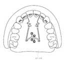
먼저, 도 1은 기존의 치열 교정용 장치를 적용한 설측 견인장치의 일 실시예가 상악에 설치된 상태를 나타낸 도면이다.1 is a view showing a state in which an embodiment of a lingual pulling apparatus to which a conventional orthodontic appliance is applied is installed in the maxilla.
이러한 설측 견인을 위해서 기존에는 악간 고정과 치아 교정력을 지탱하는 고정장치로서 미니플레이트와 미니스크류가 적용된다.For the lingual traction, miniplate and miniscrew are applied as fixation devices that support the intermaxillary fixation and orthodontic force.
도 2의 (가) 및 (나)에는, 도 1에 도시된 장치와 같이 치열 교정을 위한 고정장치로 사용될 수 있는 또 다른 타입(type)의 미니플레이트(30a)(30b)와 기존의 미니스크류(10)가 예시되어 있다.2 (a) and 2 (b) illustrate another type of
통상 미니플레이트는 미니스크류와의 결합을 위한 구멍을 적어도 하나 이상 가지며, 사용 목적 및 적용 위치에 따라 예시된 형태 이외에도 다양한 형태를 띨 수 있다.In general, the mini plate has at least one hole for engagement with the mini screw, and may take various forms in addition to the shape exemplified by the intended use and the application position.
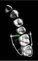
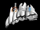
한편, 도 3은 기존의 치열 교정용 장치가 가상적으로 환자 구내에 설치된 상태를 나타낸 다른 일 실시 예로서, 교정용 고정교합면에서 살펴본 도면이고, 도 4는 도 3의 치열 교정용 장치를 설측(구개측)에서 살펴본 도면이며, 도 5는 도 3의 치열 교정용 장치를 협측에서 살펴본 도면이다.FIG. 3 is a view showing a state in which a conventional orthodontic appliance is virtually installed in a patient's premises, and is a view showing a fixed occlusal surface for orthodontic treatment. FIG. 4 is a cross- FIG. 5 is a view showing the orthodontic appliance of FIG. 3 as viewed from the buccal side.
도 3 내지 도 5는 교합되는 치아의 결손에 의해 돌출되고 협측(B)으로 약간 기울어진 상악 제2 대구치의 교정을 시뮬레이션한 것인데, 도 5에서 파란색 화살표는 교정력을, 그리고 주황색 화살표는 각 고정장치에 가해지는 반력을 나타낸다.Figs. 3 to 5 are simulations of the correction of the maxillary second molar projected by the defect of the occluded tooth and slightly inclined to the buccal side B. In Fig. 5, the blue arrow indicates the correction force and the orange arrow indicates the angle As shown in FIG.
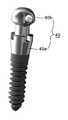
그리고, 도 6은, 도 3 내지 도 5에 도시된 치열 교정용 장치에 적용된 치과 교정치료를 위한 고정장치 중 일측 고정장치(즉, 도 5에 도시된 고정장치)의 사시도로서, 도 6의 치과 교정치료를 위한 고정장치는 잇몸의 연조직(미도시)을 지나 악골, 특히 치조골에 식립되는데, 상기 악골의 식립홀에 나사결합되는 스크류 타입의 임플란트(40)가 적용되고 있다.6 is a perspective view of one fixation device (i.e., fixation device shown in Fig. 5) among the fixation devices for orthodontic treatment applied to the orthodontic appliance shown in Figs. 3 to 5, A fixation device for orthodontic treatment is placed on a jaw, particularly a alveolar bone, through a soft tissue (not shown) of the gum, and a
현재 사용되고 있는 대부분의 치열 교정용 임플란트(40)는 미니스크류에 해당하는 작동 나사부(40a ; working thread portion)와, 교체 가능하도록 상기 작동 나사부에 착탈 가능하게 결합되는 헤드부(40b ; head portion)로 이루어지며, 통상 상기 헤드부에는 브래킷(bracket; 미도시)과 같은 다른 치아교정 장치에 부착되는 스프링, 와이어 등과 같은 주변 장치를 부착하는 데 주로 사용되는 매칭 아이릿(matching eyelet)이 구비된다.Most of the
그러나, 상술한 종래의 미니스크류(임플란트의 작동 나사부 포함)는 이를 치밀골 상에 식립되어 고정됨에 있어서, 공구인 스크류드라이버의 드라이버 팁과 미니스크류와의 적합(adaptation)이 제대로 이루어지지 않을 경우가 많으며, 그 경우 식립 도중에 미니스크류(10)가 미끄러져서 연조직 안으로 들어가거나 피질골을 관통하는 과정에서 미니스크류(10)에 구비된 십자형의 팁 적합부(즉, 결합홈)가 뭉그러지는 문제점이 있었다.However, in the conventional miniscrew (including the operating thread of the implant), the screw tip of the screwdriver, which is a tool, and the miniscrew are often not properly adapted to being fixed on the compact bone. In this case, there is a problem that the cross-shaped tip fitting portion (that is, the coupling groove) provided in the
즉, 종래의 스크류드라이버와 미니스크류는, 공구인 스크류드라이버의 십자형 팁을 미니스크류의 십자형 홈에 끼워 맞춘 상태에서, 스크류드라이버에 회전력을 가하여 미니스크류를 치밀골에 식립하게 되는데, 스크류드라이버의 십자형 팁과 미니스크류의 십자형 홈과의 적합에 의해서만 힘의 전달이 이루어질 수 있는 결합 구조이다.That is, in a conventional screw driver and a miniscrew, a screw is screwed into a cross-shaped groove of a miniscrew in a screwdriver, which is a tool, And the engagement of the force with the cross-shaped groove of the miniscrew.
따라서, 기존의 스크류드라이버와 이에 적합되는 미니스크류는, 적합(adaptation) 깊이가 얕고 적합 면적도 좁아서 회전 토크의 전달이 의도한 대로 정확하게 이루어지기 어려우며, 그로 인해 미니스크류의 식립 도중에 미니스크류가 미끄러져서 연조직 안으로 들어가거나 피질골을 관통하는 과정에서 미니스크류에 구비된 십자형의 팁 적합부가 뭉그러지는 문제점이 있었다.Therefore, conventional screwdrivers and miniscrews suitable for them are difficult to precisely perform as the rotation torque is intended, because the adaptation depth is shallow and the fit area is narrow, so that the miniscrew slips during the miniscrew installation There is a problem in that the cross-shaped tip fitting portion provided in the miniscrew is disrupted during the process of entering the soft tissue or penetrating the cortical bone.
본 발명은 상기한 제반 문제점을 해결하기 위한 것으로서, 미니스크류와 그에 적용되는 스크류드라이버가 이중 적합 구조를 이루어, 교정 치료시 미니스크류의 식립이 한층 용이하면서도 안정적으로 수행될 수 있도록 함으로써, 일반 교정환자 및 악간 고정이 필요한 악교정 수술 및 악골골절 수술 등에 효과적으로 적용할 수 있는 미니스크류 및 그에 적용되는 스크류드라이버를 제공하는데 그 목적이 있다.SUMMARY OF THE INVENTION The present invention has been made to solve the above-mentioned problems, and it is an object of the present invention to provide a mini screw and a screw driver therefor, which are double-compliant to allow miniscrew placement to be performed more easily and stably during orthodontic treatment, And a miniscrew which can be effectively applied to an orthognathic surgery and a jaw fracture surgery that require intermaxillary fixation, and a screwdriver applied thereto.
상기한 목적을 달성하기 위해 본 발명은, 악골에 고정되어 치과교정시술에서 고정원(Anchorage)으로 작용하는 치과 교정 치료용 미니스크류로서: 상기 악골에 식립되도록 나사부가 형성된 스크류 몸체와, 상기 스크류 몸체의 상측에 구비되는 스크류 헤드를 포함하여서 구성되되, 상기 스크류 헤드는 외측면이 다각형 형태를 이루도록 형성되고, 상기 스크류 헤드의 상면에는 스크류드라이버의 드라이버 팁 형상에 대응되는 결합홈이 형성된 것을 특징으로 하는 치과 교정 치료용 미니스크류가 제공된다.In order to achieve the above object, the present invention provides a dental orthodontic treatment minicule fixed to a jaw and acting as a anchor in a dental orthodontic treatment, the dental orthodontic treatment miniscrew comprising: a screw body having a threaded portion to be inserted into the jaw; Wherein the screw head has a polygonal outer surface and a coupling groove corresponding to a shape of a driver tip of the screw driver is formed on an upper surface of the screw head, A miniscrew for orthodontic treatment is provided.
한편, 상기한 목적을 달성하기 위한 본 발명의 다른 형태에 따르면, 미니스크류의 상면에 형성된 결합홈에 맞물려서 회전 토크를 전달할 수 있는 드라이버 팁을 구비한 봉상(棒狀)의 드라이버 주축과; 상기 드라이버 주축 상에 결합되는 고정체와; 상기 고정체 하부의 드라이버 주축 상에 축 방향을 따라 이동 가능하도록 설치되며, 상기 스크류 헤드의 다각형 외측면을 감싸도록 맞물려 상기 드라이버 팁과 함께 미니스크류에 회전 토크를 전달할 수 있는 스크류 인클로우저(screw enclosure)와; 상기 스크류 인클로우저에 대해 드라이버 주축 하방으로 이동하려는 경향성을 갖도록 상기 고정체와 스크류 인클로우저 사이에 설치되는 탄성부재;를 포함하여 구성되는 것을 특징으로 하는 치과 교정 치료용 스크류드라이버가 제공된다.According to another aspect of the present invention, there is provided a screwdriver, comprising: a rod-shaped screw shaft having a screwdriver capable of engaging with an engaging groove formed on an upper surface of a miniscrew to transmit a rotational torque; A fixture coupled to the driver spindle; A screw enclosure installed to be movable along an axial direction on a screw shaft of a screw driver installed at a lower portion of the fixing body and adapted to engage with the screw tip to enclose a polygonal outer surface of the screw head, Wow; And an elastic member provided between the fixture and the screw enclosure so as to have a tendency to move downwardly of the screw spindle with respect to the screw enclosure.
한편, 상기한 목적을 달성하기 위한 본 발명의 또 다른 형태에 따르면, 악골에 식립되도록 나사부가 형성된 스크류 몸체와, 상기 스크류 몸체의 상측에 구비되되 외측면이 다각형 형태를 이루고 상면에는 스크류드라이버의 팁 형상에 대응하는 결합홈이 구비된 스크류 헤드를 포함하는 미니스크류와;According to another aspect of the present invention, there is provided a screw member comprising: a screw body formed with a threaded portion to be inserted into a jaw; an upper side of the screw body having a polygonal outer surface; A miniscrew including a screw head having an engaging groove corresponding to the shape;
상기 미니스크류에 이중 적합되도록, 상기 미니스크류의 스크류 헤드 상면에 형성된 결합홈에 적합되는 드라이버 팁을 갖는 드라이버 주축과, 상기 드라이버 팁을 감싸도록 상기 드라이버 주축 상에 구비되며 상기 미니스크류에 결합시 스크류 헤드의 다각형 외측면에 맞물리게 되는 스크류 인클로우저를 포함하는 치과 교정 치료용 스크류드라이버 툴 셋트(Screwdriver tool set)가 제공된다.A screwdriver having a screwdriver having a screwdriver tip adapted to an engaging groove formed on an upper surface of the screw head of the miniscrew so as to be duplexed with the miniscrew and a screwdriver provided on the screwdriver to surround the screwdriver, There is provided a screwdriver tool set for a dental orthodontic treatment including a screw enclosure which is engaged with the polygonal outer surface of the head.
본 발명에 따른 이중 적합되는 미니스크류 및 그에 적용되는 스크류드라이버는 다음과 같은 효과를 제공한다.The double screw mini screw according to the present invention and the screw driver applied thereto provide the following effects.
본 발명에 따르면, 미니스크류와 스크류드라이버가 이중 적합됨에 따라 교정 치료를 위한 미니플레이트 고정용 미니스크류의 식립이 안정적으로 이루어지게 된다.According to the present invention, since the miniscrew and the screwdriver are double-fitted, the miniscrew for fixing the miniplate for the orthodontic treatment can be stably placed.
즉, 본 발명은 스크류드라이버의 드라이버 팁이 미니스크류 상면의 결합홈에 적합될 때 스크류 인클로우저가 미니스크류의 외면을 감싸면서 적합 됨에 따라, 미니스크류와 스크류드라이버가 이중 적합 구조를 이룸으로써, 미니플레이트 고정용 미니스크류 식립 도중에 스크류가 미끄러져 연조직 안으로 들어가거나 피질골을 관통하는 과정에서 드라이버 팁이 뭉그러지는 현상이 방지된다.That is, according to the present invention, when the screw tip of the screwdriver is adapted to the coupling groove on the upper surface of the minidisc, the screw enclosure is fitted while covering the outer surface of the minidisc, so that the minidiscrew and the screwdriver have a double- The screw tip slides during the fixation miniscrew placement to prevent the tip of the screwdriver from being broken during insertion into the soft tissue or through the cortical bone.
따라서, 본 발명의 이중 적합되는 미니스크류 및 그에 적용되는 스크류드라이버는, 일반 교정환자 및 악간 고정이 필요한 악교정 수술 및 악골골절 수술 등에 효과적으로 적용할 수 있다.Therefore, the double screw mini screw of the present invention and the screw driver applied thereto can be effectively applied to orthodontic patients and orthodontic surgery and jaw fracture surgery that require intercuspal fixation.
도 1은 기존의 치열 교정용 장치를 적용한 설측 견인장치의 일 실시예가 상악에 설치된 상태를 나타낸 도면
도 2의 (가) 및 (나)는 도 1에 개시된 기존의 치열 교정용 고정장치의 다른 구조 예를 나타낸 사시도
도 3은 기존의 치열 교정용 장치가 가상적으로 환자 구내에 설치된 상태를 나타낸 다른 일 실시예로서, 교정용 고정교합면에서 살펴본 참고 도면
도 4는 도 3의 치열 교정용 장치를 설측(구개측)에서 살펴본 참고 도면.
도 5는 도 3의 치열 교정용 장치를 협측에서 살펴본 참고 도면
도 6은 도 3 및 도 4에 개시된 기존의 치열 교정용 고정장치(즉, 임플란트)의 사시도
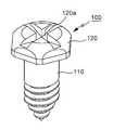
도 7은 본 발명에 따른 이중 적합 구조의 치열 교정용 미니스크류 사시도
도 8은 본 발명에 따른 스크류드라이버의 요부 구성 단면도
도 9a 내지 도 9d는 본 발명의 미니스크류 및 스크류드라이버를 작용을 예시한 단면도로서,
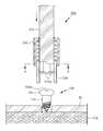
도 9a는 미니스크류와 스크류드라이버의 적합 전 상태를 보여주는 도면
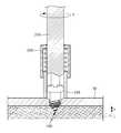
도 9b는 미니스크류의 결합홈에 스크류드라이버의 드라이버 팁이 삽입된 상태를 보여주는 도면
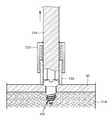
도 9c는 미니스크류의 식립 도중 상태도로서, 스크류드라이버의 스크류 인클로우저가 미니플레이트에 닿은 시점의 상태를 보여주는 도면
도 9d는 미니스크류 식립 완료 시점의 상태도
도 10은 도 9a의 A-A선을 따른 단면도1 is a view showing a state in which an embodiment of a lingual pulling apparatus to which a conventional orthodontic appliance is applied is installed in the maxilla;
2 (a) and 2 (b) are perspective views showing another example of the structure of the conventional orthodontic appliance fixing apparatus disclosed in Fig. 1
FIG. 3 is another embodiment showing a state in which a conventional orthodontic appliance is virtually installed in a patient's mouth,
Fig. 4 is a reference view of the apparatus for orthodontic treatment of Fig. 3 taken from the lingual side; Fig.
FIG. 5 is a view showing the apparatus for orthodontics of FIG.
6 is a perspective view of a conventional orthodontic fixation device (i.e., an implant) disclosed in Figs. 3 and 4. Fig.
Fig. 7 is a perspective view of a mini screw for orthodontics according to the present invention,
Fig. 8 is a cross-sectional view of a main part of a screwdriver according to the present invention
9A to 9D are cross-sectional views illustrating the operation of the mini screw and screw driver of the present invention,
9A is a view showing a state before fitting of a miniscrew and a screwdriver
FIG. 9B is a view showing a state in which a screwdriver's driver tip is inserted into the engagement groove of the mini screw; FIG.
FIG. 9C is a state diagram during the mini-screw installation, showing a state when the screw enclosure of the screw driver contacts the mini plate; FIG.
FIG. 9D is a state diagram of the miniscrew-
10 is a sectional view taken along the line AA in Fig.
이하, 본 발명의 바람직한 실시 예들에 대해 첨부도면 도 7 내지 도 10을 참조하여 상세히 설명하면 다음과 같다.Hereinafter, preferred embodiments of the present invention will be described in detail with reference to FIGS. 7 to 10.
먼저, 도 7을 참조하면, 본 발명에 적용되는 치과 교정 치료용 미니스크류(100)는, 악골에 고정되어 치과교정시술에서 고정원(Anchorage)으로 작용하는 것으로서, 상기 악골에 식립되도록 나사부가 형성된 스크류 몸체(110)와, 상기 스크류 몸체(110)의 상측에 구비되며 외측면이 다각형 형태를 이루는 스크류 헤드(120)를 포함하여서 구성된다.7, the dental orthodontic treatment miniscrew 100 according to the present invention is fixed to the jaw and functions as an anchor in the dental orthodontic treatment. A
이때, 상기 스크류 헤드(120)의 상면에는 스크류드라이버(200)의 드라이버 드라이버 팁(210a) 형상에 대응되는 형상의 결합홈(120a)이 형성된다.At this time, a
상기 미니스크류(100)의 상면에 형성되는 결합홈(120a)은, 일자형이나 십자형 홈, 혹은 다각형 모양의 홈을 이룰 수 있다.The
한편, 도 7 내지 도 10을 참조하면, 상술한 구성의 본 발명의 미니스크류(100)에 적용되는 본 발명의 치과 교정 치료용 스크류드라이버(200)는, 미니스크류(100)의 상면에 형성된 결합홈(120a)에 맞물려서 회전 토크(T)를 전달할 수 있는 드라이버 드라이버 팁(210a)을 구비한 봉상(棒狀)의 드라이버 주축(210)과, 상기 드라이버 주축(210) 상에 결합되는 고정체(220)와, 상기 고정체(220) 하부의 드라이버 주축(210) 상에 축 방향을 따라 이동 가능하도록 설치되며, 상기 스크류 헤드(120)의 외측면을 감싸도록 맞물려 상기 드라이버 드라이버 팁(210a)과 함께 미니스크류(100)에 회전 토크(T)를 전달할 수 있는 스크류 인클로우저(230; Screw enclosure), 상기 스크류 인클로우저(230)에 대해 드라이버 주축 하방으로 이동하려는 경향성을 갖도록 상기 고정체(220)와 스크류 인클로우저(230) 사이에 설치되는 탄성부재(240)(예; 압축코일 스프링)를 포함하여 구성된다.7 to 10, the
이때, 상기 고정체(220)는 통 모양으로 형성되어, 상기 드라이버 주축(210)을 따라 승강하는 스크류 인클로우저(230)를 외측에서 감싸서 지지하면서 안내할 수 있도록 구성됨이 바람직하다.At this time, the
한편, 상기 스크류드라이버(200)의 드라이버 드라이버 팁(210a)은 상기 미니스크류(100) 상면의 결합홈(120a)의 홈 모양에 대응할 수 있는 형태를 이루도록 구성된다.The
즉, 결합홈(120a)이 십자형이면 드라이버 드라이버 팁(210a)도 십자형을 이루고, 결합홈이 다각형 모양의 이면 드라이버 팁도 다각형 모양을 이루도록 구성된다.That is, if the
한편, 상기 스크류 인클로우저(230)는, 상기 드라이버 주축(210)으로부터 회전력을 전달받을 수 있도록 상기 드라이버 주축(210)의 외면에 맞물리는 구조를 이루도록 형성된다. 다시 말해서, 본 실시예의 도면들(도 8 내지 도 10)에 도시된 것처럼, 상기 스크류드라이버(200)가 미니스크류(100)에 회전 토크(회전력)을 가할 때 상기 드라이버 주축(210)과 스크류 인클로우저(230)는 상대 회전이 방지되는 구조임을 알 수 있으며, 상기 드라이버 주축(210)과 스크류 인클로우저(230)가 각각 동시에 미니스크류(100)에 회전 토크를 가하게 된다. 예컨대, 상기 드라이버 주축(210)이 다각형 봉 형태를 이루고, 이에 맞물리는 스크류 인클로우저(230)가 다각형 홈을 갖는 형태를 이루는 것이 바람직하나(도 10 참조), 이에 한정되지는 않는다.Meanwhile, the
즉, 상기 드라이버 주축(210)의 외면이 다각형 구조가 아니라도 드라이버 주축(210)의 회전시, 스크류 인클로우저(230)로 드라이버 주축(210)의 회전력만 전달될 수 있는 구조이면 대신 적용 가능한데, 예컨대 단면이 원형인 봉상의 드라이버 주축 외주면 상에 돌기가 형성되고, 상기 돌기에 대응하는 형합홈이 스크류 인클로우저(230)에 형성되어 상기 돌기와 형합홈의 맞물림에 의해 드라이버 주축의 회전력이 전달될 수 있을 것이다.That is, if the outer surface of the
한편, 상기 스크류 인클로우저(230)의 끝단은, 상기 탄성부재(240)에 가해지는 힘이 없는 상태에서, 상기 스크류드라이버(200)의 드라이버 드라이버 팁(210a)의 끝단 보다는 낮은 높이로 위치하는 것이 바람직하다. 상기 탄성부재(240)는, 도 8에 도시된 바와 같이, 상기 스크류 인클로우저(230)를 하방으로 탄력 지지한다.The end of the
이는, 스크류드라이버(200)의 드라이버 드라이버 팁(210a)이 미니스크류(100)의 결합홈(120a)에 삽입될 때 스크류 인클로우저(230)는 미니스크류(100)의 다각형인 스크류 헤드(120) 외면을 감싸게 됨으로써, 미니스크류(100)와 스크류드라이버(200) 간의 적합 구조가 저절로 이중 적합 구조를 이루도록 하기 위함이다.This is because when the
한편, 상기 고정체(220)의 하단부와 스크류 인클로우저(230)의 상단부에는 상호 간섭에 의해 스크류 인클로우저(230)가 고정체(220)에서 이탈되는 것을 방지하도록 걸림턱부가 각각 구비된다.The lower end of the fixing
이와 같이 구성된 본 발명의 작용은 다음과 같다.The operation of the present invention thus configured is as follows.
본 발명의 미니스크류(100)와 스크류드라이버(200)에 따르면, 미니스크류(100)와 스크류드라이버(200)가 이중 적합됨에 따라 교정 치료를 위한 미니플레이트 고정용 미니스크류(100)의 식립이 안정적으로 이루어지게 된다.According to the
즉, 교정 치료를 위한 미니플레이트 고정용 미니스크류(100)는 연조직(미도시)을 절개한 후, 치밀골 상에 고정되어야 하는데, 본 발명에 따르면 미니스크류(100)의 스크류 헤드(120) 부분이 이중 적합 가능한 구조로 만들어지고, 이에 맞추어 스크류드라이버(200)도 드라이버 드라이버 팁(210a)과 스크류 인클로우저(230)에 의해 이중 적합 가능한 구조로 구성된다.That is, the
도 9a 내지 도 9d, 및 도 10을 참조하여 교정 치료를 위한 미니플레이트 고정용 미니스크류(100)의 식립 과정에 대해 개략적으로 설명한다.9A to 9D, and 10, a process of placing the miniplate fixing
먼저, 교정 치료를 위한 미니플레이트(30) 고정용 미니스크류(100)는 연조직(도시는 생략함)이 절개된 상태에서 악골 상에 고정되어야 하는데, 도 9a 상태에서 미니스크류(100)와 스크류드라이버(200)를 대략 일렬로 맞춘 다음, 도 9b와 같이 스크류드라이버(200)의 드라이버 드라이버 팁(210a)이 미니스크류(100)의 스크류 헤드(120) 상면에 구비된 십자형 결합홈(120a)에 적합되도록 서로 형합시키게 된다.In the state of FIG. 9A, the
이때, 스크류드라이버(200)의 드라이버 드라이버 팁(210a)이 스크류 헤드(120) 상면의 십자형 결합홈(120a)에 맞물리는 한편, 상기 스크류드라이버(200)의 스크류 인클로우저(230)는 미니스크류(100)의 다각형인 스크류 헤드(120) 외면을 감싸게 되며, 이로써 미니스크류(100)와 스크류드라이버(200)는 이중 적합 상태를 이루게 된다.At this time, the
이 상태에서 상기 스크류드라이버(200)의 드라이버 주축(210)이 회전하게 되면, 상기 드라이버 주축(210)의 회전력(T)은 드라이버 드라이버 팁(210a) 및 스크류 인클로우저(230)를 통해 미니스크류(100) 측으로 안정적으로 전달된다.In this state, when the
도 9c는 스크류드라이버(200)에 이중 적합된 미니스크류(100)가 치밀골 상에 식립되는 도중의 상태를 나타낸 것으로, 스크류드라이버(200)의 스크류 인클로우저(230)가 미니플레이트(30)에 막 닿은 시점을 나타낸 것이다.9C shows a state in which the
이때는 탄성부재(240)의 압축이 아직 일어나기 전 상태이므로, 미니스크류(100)의 식립 깊이(d)는, 도 9b에 도시된 스크류 인클로우저(230) 하단으로부터 미니플레이트 상면 까지의 높이(h)와 같다.The minimum depth d of the
도 9c를 참조하면, 이 시점부터 미니스크류(100)가 치밀골 상으로 더 깊이 식립됨에 따라, 스크류드라이버(200)의 고정체(220)와 스크류 인클로우저(230) 사이에 구비된 탄성부재(240)는 점점 압축되며, 상기 고정체(220) 내측에서 스크류 인클로우저(230)는 드라이버 주축(210)을 따라 점점 상승하게 된다. 따라서, 상기 스크류 인클로우저(230)는, 미니스크류(100)에 회전 토크가 가해지는 도중에 상기 드라이버 주축(210)의 축방향 이동이 가능하며, 미니스크류(100)를 식립하는 도중에 상승에 의해 미니스크류(110)에서 분리될 수도 있다.The elastic member 240 provided between the
이 과정에서 상기 미니스크류(100)의 스크류 헤드(120)와 스크류드라이버(200)의 이중 적합은 지속적이면서 안정적으로 유지되며, 이에 따라 도 9d에 도시된 바와 같이 상기 미니스크류(100)의 식립이 끝까지 이루어지게 되며, 식립이 완료되면 스크류드라이버(200)를 화살표로 표시한 것과 같이 위쪽으로 올려 미니스크류(100)로부터 분리시킬 수 있게 된다.The double fit between the
한편, 상기의 작용 과정에서 드라이버 주축(210)의 회전력은 다양하게 얻어질 수 있다. 즉, 통상 치과에서 많이 사용되는 기구인 핸드피스(미도시) 선단의 헤드에 드라이버 주축(210)이 끼워져 장착됨으로써 핸드피스를 통해 드라이버 주축(210)에 회전 토크(T)가 전달될 수 있다. 그 밖에 상기 드라이버 주축(210) 끝단에 일반적인 드라이버에 적용되는 손잡이가 구비되어 진료를 행하는 주치의가 손잡이를 잡고 돌려서 회전 토크(T)를 드라이버 주축(210)을 통해 미니스크류(100) 측으로 전달할 수도 있을 것이다.Meanwhile, in the above operation, the rotational force of the
상술한 구성 및 작용의 본 발명에 따르면, 스크류드라이버(200)의 드라이버 드라이버 팁(210a)이 미니스크류(100) 상면의 결합홈(120a)에 적합될 때 스크류 인클로우저(230)가 미니스크류(100)의 외면을 감싸면서 이중 적합됨에 따라, 기존과는 달리, 식립 도중에 스크류가 미끄러져 연조직 안으로 들어가거나 피질골을 관통하는 과정에서 드라이버 팁이 뭉그러지는 현상이 미연에 방지된다.According to the present invention, when the
즉, 기존의 미니스크류와 스크류드라이버는, 교정 치료를 위한 미니플레이트 고정용 미니스크류의 식립 도중에 스크류가 미끄러져서 연조직 안으로 들어가거나 피질골을 관통하는 과정에서 드라이버 팁이 뭉그러지는 현상이 발생하였으나, 본 발명의 이중 적합 구조에 따르면 미니스크류가 식립되는 동안 이중으로 맞물림이 유지되어 이러한 기존 문제점들이 효과적으로 해소되는 것이다.That is, in the conventional miniscrew and screwdriver, the screw tip slips during insertion of the miniplate fixing mini screw for orthodontic treatment and enters the soft tissue or passes through the cortical bone. However, The dual fit structure allows the double screw engagement to be maintained while the mini screw is being placed, effectively eliminating these existing problems.
따라서, 본 발명은 교정 치료시 일반 교정환자 및 악간 고정이 필요한 악교정 수술 및 악골골절 수술 등에 효과적으로 적용할 수 있다.
Therefore, the present invention can be effectively applied to orthodontic patients in orthodontic treatment, and orthognathic surgery and osteoarthritic surgery in which intercostal fixation is required.
이상과 같이 본 발명에 따른 실시 예를 살펴보았으며, 앞서 설명된 실시 예 이외에도 본 발명이 그 취지나 범주에서 벗어남이 없이 다른 특정 형태로 구체화될 수 있다는 사실은 해당 기술에 통상의 지식을 가진 이들에게는 자명한 것이다.It will be apparent to those skilled in the art that the present invention may be embodied in other specific forms without departing from the spirit or scope of the invention as defined in the appended claims. .
예컨대, 상술한 실시 예에서는 상기 고정체(220)의 하단부와 스크류 인클로우저(230)의 상단부에는 상호 간섭에 의해 스크류 인클로우저(230)가 고정체(220)에서 이탈되는 것을 방지하는 걸림턱부가 각각 구비될 수 있다고 하였으나, 탄성부재(240)의 양측 단부가 고정체와 스크류 인클로우저 측에 각각 고정(fixing)됨으로써 스크류 인클로우저(230)가 고정체(220)로부터 이탈이 방지되도록 할 수도 있다.For example, in the above-described embodiment, the lower end of the fixing
따라서, 상술한 실시 예는 제한적인 것이 아니라 예시적인 것으로 여겨져야 하고, 이에 따라 본 발명은 상술한 설명에 한정되지 않고 첨부된 청구항의 범주 및 그 동등 범위 내에서 변경될 수도 있다Accordingly, the above-described embodiments are to be considered as illustrative and not restrictive, and the invention is not to be limited to the details given above, but may be modified within the scope of the appended claims and equivalents thereof
100: 미니스크류110: 스크류 몸체
120: 스크류 헤드120a: 결합홈
200: 스크류드라이버210: 드라이버 주축
210a: 드라이버 팁220: 고정체
230: 스크류 인클로우저240: 탄성부재100: miniscrew 110: screw body
120: screw
200: screw driver 210: driver spindle
210a: Driver tip 220: Fixture
230: screw enclosure 240: elastic member
Claims (8)
Translated fromKorean상기 스크류 헤드의 상면에 형성된 결합홈에 맞물려서 상기 미니스크류에 회전 토크를 전달할 수 있는 드라이버 팁을 구비한 봉상(棒狀)의 드라이버 주축과;
상기 드라이버 주축 상에 결합되는 고정체와;
상기 고정체 하부의 드라이버 주축 상에 축 방향을 따라 이동 가능하도록 설치되며, 상기 스크류 헤드의 외측면을 감싸도록 상기 스크류 헤드에 맞물려 상기 드라이버 팁과 함께 상기 미니스크류에 회전 토크를 전달할 수 있는 스크류 인클로우저(screw enclosure)와;
상기 고정체와 스크류 인클로우저 사이에 설치되며, 상기 스크류 인클로우저를 하방으로 탄력 지지하는 탄성부재;를 포함하여 구성되는 것을 특징으로 하는 치과 교정 치료용 스크류드라이버.A screw driver for dental orthodontic treatment for applying a rotational torque to a miniscrew having a screw head,
A rod-shaped driver main shaft having a driver tip capable of engaging with an engaging groove formed on an upper surface of the screw head to transmit a rotation torque to the miniscrew;
A fixture coupled to the driver spindle;
A screw shaft mounted on the screw shaft of the lower portion of the fixture so as to be movable along the axial direction and capable of transmitting a rotation torque to the miniscrew together with the screw tip to be engaged with the screw head so as to surround the outer surface of the screw head; a screw enclosure;
And an elastic member provided between the fixture and the screw enclosure and elastically supporting the screw enclosure downward.
상기 고정체는 통형상으로 형성되어, 상기 드라이버 주축을 따라 승강하는 스크류 인클로우저를 외측에서 감싸서 지지하면서 안내할 수 있도록 구성되는 것을 특징으로 하는 치과 교정 치료용 스크류드라이버.The method of claim 3,
Wherein the fixture is formed in a tubular shape so that the fixture is guided while guiding the screw enclosure lifted and lowered along the screw shaft.
상기 스크류드라이버의 드라이버 팁은 상기 미니스크류 상면의 결합홈의 홈 모양에 대응할 수 있는 형태를 이루도록 구성되는 특징으로 하는 치과 교정 치료용 스크류드라이버.The method of claim 3,
Wherein the screwdriver tip of the screwdriver is configured so as to correspond to the groove shape of the coupling groove of the upper surface of the miniscrew.
상기 스크류 인클로우저는,
상기 드라이버 주축으로부터 회전력을 전달받을 수 있도록 상기 드라이버 주축에 맞물리는 구조를 이루도록 형성됨을 특징으로 하는 치과 교정 치료용 스크류드라이버.The method of claim 3,
In the screw enclosure,
Wherein the screw driver is configured to engage with the main spindle of the driver so as to receive a rotational force from the main spindle of the screw.
상기 스크류 인클로우저의 끝단은,
상기 탄성부재에 가해지는 힘이 없는 상태에서,
상기 스크류드라이버의 팁의 끝단보다는 낮은 높이로 위치하는 것을 특징으로 하는 치과 교정 치료용 스크류드라이버.The method of claim 3,
The end of the screw enclosure
In a state in which there is no force applied to the elastic member,
Wherein the screw driver is positioned at a lower height than the tip of the screw driver.
상기 미니스크류의 식립을 위해 상기 미니스크류에 회전 토크를 가하는 치과 교정 치료용 스크류드라이버;를 포함하는 치과 교정 치료용 스크류드라이버 툴 셋트로서:
상기 스크류드라이버는;
상기 스크류 헤드의 상면에 형성된 결합홈에 맞물려서 상기 미니스크류에 회전 토크를 전달할 수 있는 드라이버 팁을 구비한 봉상(棒狀)의 드라이버 주축과,
상기 드라이버 주축 상에 결합되는 고정체와,
상기 고정체 하부의 드라이버 주축 상에 축 방향을 따라 이동 가능하도록 설치되며, 상기 스크류 헤드의 외측면을 감싸도록 상기 스크류 헤드에 맞물려 상기 드라이버 팁과 함께 상기 미니스크류에 회전 토크를 전달할 수 있는 스크류 인클로우저(screw enclosure)와,
상기 고정체와 스크류 인클로우저 사이에 설치되며, 상기 스크류 인클로우저를 하방으로 탄력 지지하는 탄성부재를 포함하는 치과 교정 치료용 스크류드라이버 툴 셋트.And a screw head provided on the screw body and having a polygonal outer surface and an engaging groove corresponding to a tip shape of a screwdriver on an upper surface of the screw body;
And a screw driver for a dental orthodontic treatment applying a rotational torque to the miniscrew for placing the miniscrew, the screwdriver tool set comprising:
Wherein the screw driver comprises:
A rod-shaped driver main shaft having a driver tip capable of engaging with an engaging groove formed on an upper surface of the screw head to transmit a rotation torque to the miniscrew;
A fixed body coupled to the driver spindle,
A screw shaft mounted on the screw shaft of the lower portion of the fixture so as to be movable along the axial direction and capable of transmitting a rotation torque to the miniscrew together with the screw tip to be engaged with the screw head so as to surround the outer surface of the screw head; a screw enclosure,
And a resilient member provided between the fixture and the screw enclosure for elastically supporting the screw enclosure downward.
Priority Applications (1)
| Application Number | Priority Date | Filing Date | Title |
|---|---|---|---|
| KR1020150167302AKR101801316B1 (en) | 2015-11-27 | 2015-11-27 | Miniscrew with double adopted head for screwdriver tip and screwdriver applied thereto |
Applications Claiming Priority (1)
| Application Number | Priority Date | Filing Date | Title |
|---|---|---|---|
| KR1020150167302AKR101801316B1 (en) | 2015-11-27 | 2015-11-27 | Miniscrew with double adopted head for screwdriver tip and screwdriver applied thereto |
Publications (2)
| Publication Number | Publication Date |
|---|---|
| KR20170062004A KR20170062004A (en) | 2017-06-07 |
| KR101801316B1true KR101801316B1 (en) | 2017-11-24 |
Family
ID=59223625
Family Applications (1)
| Application Number | Title | Priority Date | Filing Date |
|---|---|---|---|
| KR1020150167302AActiveKR101801316B1 (en) | 2015-11-27 | 2015-11-27 | Miniscrew with double adopted head for screwdriver tip and screwdriver applied thereto |
Country Status (1)
| Country | Link |
|---|---|
| KR (1) | KR101801316B1 (en) |
Families Citing this family (1)
| Publication number | Priority date | Publication date | Assignee | Title |
|---|---|---|---|---|
| IL269728B (en)* | 2019-09-26 | 2020-09-30 | Noris Medical Ltd | External drive implantation apparatus for bendable collar implants and method |
Citations (2)
| Publication number | Priority date | Publication date | Assignee | Title |
|---|---|---|---|---|
| JP2000257615A (en) | 1999-03-08 | 2000-09-19 | Keiji Omori | Screw and driver |
| KR100475269B1 (en)* | 2003-11-04 | 2005-03-14 | 주식회사 제일메디칼코퍼레이션 | Bone screw for medical care |
- 2015
- 2015-11-27KRKR1020150167302Apatent/KR101801316B1/enactiveActive
Patent Citations (2)
| Publication number | Priority date | Publication date | Assignee | Title |
|---|---|---|---|---|
| JP2000257615A (en) | 1999-03-08 | 2000-09-19 | Keiji Omori | Screw and driver |
| KR100475269B1 (en)* | 2003-11-04 | 2005-03-14 | 주식회사 제일메디칼코퍼레이션 | Bone screw for medical care |
Also Published As
| Publication number | Publication date |
|---|---|
| KR20170062004A (en) | 2017-06-07 |
Similar Documents
| Publication | Publication Date | Title |
|---|---|---|
| US10687922B2 (en) | Casting jig for chair-side manufacture of customizable sculptable anatomical healing caps | |
| US6672870B2 (en) | Method and instrumentation for attaching dentures | |
| US9572640B2 (en) | Casting jig for chair-side manufacture of customizable sculptable anatomical healing caps | |
| EP2706948B1 (en) | Device for causing tooth movement | |
| US5853291A (en) | Subperiosteal bone anchor | |
| US6302687B1 (en) | Appliance and method for mandibular widening by symphyseal distraction osteogenesis | |
| US20130252195A1 (en) | Orthodontic expander system and method | |
| WO2014088116A1 (en) | Fastening force maintaining device for screw, and screw equipped with fastening force maintaining device | |
| US7637741B2 (en) | Orthodontic anchor | |
| KR101671730B1 (en) | Palatal Expander And Bracket For The Same | |
| KR101551381B1 (en) | Anchorage for orthodontic treatment or maxillofacial surgery | |
| US20230263603A1 (en) | Implantation system and add-on element for an implantation system | |
| US20090197218A1 (en) | Universal transitional abutment | |
| KR101801316B1 (en) | Miniscrew with double adopted head for screwdriver tip and screwdriver applied thereto | |
| KR100541066B1 (en) | Orthodontic Micro Implant Torque Driver | |
| JP3651640B2 (en) | Orthodontic support | |
| KR200459306Y1 (en) | Screw for Anchor of Orthodontic Treatment | |
| KR102106820B1 (en) | The device for fixing a apparatus in the mouth | |
| JP2017529980A (en) | System and method for dental implant repair | |
| KR100893787B1 (en) | Hand Contra-Angle Micro Implant Torque Driver | |
| US20100136504A1 (en) | Dual option orthodontic implant driver for placing and tightening implants | |
| KR101897702B1 (en) | Palatal anchorage for orthodontic treatment | |
| KR101833808B1 (en) | Palatal Anchorage For Orthodontic Treatment And Orthodontic Supporter For The Same | |
| WO2018094486A1 (en) | Pincers for the extraction of teeth and residual dental roots | |
| RU2647156C1 (en) | Orthodontic abutment |
Legal Events
| Date | Code | Title | Description |
|---|---|---|---|
| A201 | Request for examination | ||
| PA0109 | Patent application | St.27 status event code:A-0-1-A10-A12-nap-PA0109 | |
| PA0201 | Request for examination | St.27 status event code:A-1-2-D10-D11-exm-PA0201 | |
| D13-X000 | Search requested | St.27 status event code:A-1-2-D10-D13-srh-X000 | |
| D14-X000 | Search report completed | St.27 status event code:A-1-2-D10-D14-srh-X000 | |
| E902 | Notification of reason for refusal | ||
| PE0902 | Notice of grounds for rejection | St.27 status event code:A-1-2-D10-D21-exm-PE0902 | |
| T11-X000 | Administrative time limit extension requested | St.27 status event code:U-3-3-T10-T11-oth-X000 | |
| P11-X000 | Amendment of application requested | St.27 status event code:A-2-2-P10-P11-nap-X000 | |
| P13-X000 | Application amended | St.27 status event code:A-2-2-P10-P13-nap-X000 | |
| T11-X000 | Administrative time limit extension requested | St.27 status event code:U-3-3-T10-T11-oth-X000 | |
| P11-X000 | Amendment of application requested | St.27 status event code:A-2-2-P10-P11-nap-X000 | |
| P13-X000 | Application amended | St.27 status event code:A-2-2-P10-P13-nap-X000 | |
| T11-X000 | Administrative time limit extension requested | St.27 status event code:U-3-3-T10-T11-oth-X000 | |
| P11-X000 | Amendment of application requested | St.27 status event code:A-2-2-P10-P11-nap-X000 | |
| P13-X000 | Application amended | St.27 status event code:A-2-2-P10-P13-nap-X000 | |
| T11-X000 | Administrative time limit extension requested | St.27 status event code:U-3-3-T10-T11-oth-X000 | |
| E13-X000 | Pre-grant limitation requested | St.27 status event code:A-2-3-E10-E13-lim-X000 | |
| P11-X000 | Amendment of application requested | St.27 status event code:A-2-2-P10-P11-nap-X000 | |
| P13-X000 | Application amended | St.27 status event code:A-2-2-P10-P13-nap-X000 | |
| PG1501 | Laying open of application | St.27 status event code:A-1-1-Q10-Q12-nap-PG1501 | |
| E701 | Decision to grant or registration of patent right | ||
| PE0701 | Decision of registration | St.27 status event code:A-1-2-D10-D22-exm-PE0701 | |
| GRNT | Written decision to grant | ||
| PR0701 | Registration of establishment | St.27 status event code:A-2-4-F10-F11-exm-PR0701 | |
| PR1002 | Payment of registration fee | St.27 status event code:A-2-2-U10-U11-oth-PR1002 Fee payment year number:1 | |
| PG1601 | Publication of registration | St.27 status event code:A-4-4-Q10-Q13-nap-PG1601 | |
| P22-X000 | Classification modified | St.27 status event code:A-4-4-P10-P22-nap-X000 | |
| R18-X000 | Changes to party contact information recorded | St.27 status event code:A-5-5-R10-R18-oth-X000 | |
| PR1001 | Payment of annual fee | St.27 status event code:A-4-4-U10-U11-oth-PR1001 Fee payment year number:4 | |
| PR1001 | Payment of annual fee | St.27 status event code:A-4-4-U10-U11-oth-PR1001 Fee payment year number:5 | |
| PR1001 | Payment of annual fee | St.27 status event code:A-4-4-U10-U11-oth-PR1001 Fee payment year number:6 | |
| PR1001 | Payment of annual fee | St.27 status event code:A-4-4-U10-U11-oth-PR1001 Fee payment year number:7 | |
| R18-X000 | Changes to party contact information recorded | St.27 status event code:A-5-5-R10-R18-oth-X000 | |
| PR1001 | Payment of annual fee | St.27 status event code:A-4-4-U10-U11-oth-PR1001 Fee payment year number:8 | |
| PR1001 | Payment of annual fee | St.27 status event code:A-4-4-U10-U11-oth-PR1001 Fee payment year number:9 |