KR101799875B1 - Pos terminal - Google Patents
Pos terminalDownload PDFInfo
- Publication number
- KR101799875B1 KR101799875B1KR1020160010768AKR20160010768AKR101799875B1KR 101799875 B1KR101799875 B1KR 101799875B1KR 1020160010768 AKR1020160010768 AKR 1020160010768AKR 20160010768 AKR20160010768 AKR 20160010768AKR 101799875 B1KR101799875 B1KR 101799875B1
- Authority
- KR
- South Korea
- Prior art keywords
- display device
- main body
- mode
- pos terminal
- information
- Prior art date
- Legal status (The legal status is an assumption and is not a legal conclusion. Google has not performed a legal analysis and makes no representation as to the accuracy of the status listed.)
- Expired - Fee Related
Links
Images


Classifications
- G—PHYSICS
- G06—COMPUTING OR CALCULATING; COUNTING
- G06Q—INFORMATION AND COMMUNICATION TECHNOLOGY [ICT] SPECIALLY ADAPTED FOR ADMINISTRATIVE, COMMERCIAL, FINANCIAL, MANAGERIAL OR SUPERVISORY PURPOSES; SYSTEMS OR METHODS SPECIALLY ADAPTED FOR ADMINISTRATIVE, COMMERCIAL, FINANCIAL, MANAGERIAL OR SUPERVISORY PURPOSES, NOT OTHERWISE PROVIDED FOR
- G06Q20/00—Payment architectures, schemes or protocols
- G06Q20/08—Payment architectures
- G06Q20/20—Point-of-sale [POS] network systems
- G—PHYSICS
- G06—COMPUTING OR CALCULATING; COUNTING
- G06Q—INFORMATION AND COMMUNICATION TECHNOLOGY [ICT] SPECIALLY ADAPTED FOR ADMINISTRATIVE, COMMERCIAL, FINANCIAL, MANAGERIAL OR SUPERVISORY PURPOSES; SYSTEMS OR METHODS SPECIALLY ADAPTED FOR ADMINISTRATIVE, COMMERCIAL, FINANCIAL, MANAGERIAL OR SUPERVISORY PURPOSES, NOT OTHERWISE PROVIDED FOR
- G06Q20/00—Payment architectures, schemes or protocols
- G06Q20/04—Payment circuits
- H—ELECTRICITY
- H02—GENERATION; CONVERSION OR DISTRIBUTION OF ELECTRIC POWER
- H02J—CIRCUIT ARRANGEMENTS OR SYSTEMS FOR SUPPLYING OR DISTRIBUTING ELECTRIC POWER; SYSTEMS FOR STORING ELECTRIC ENERGY
- H02J7/00—Circuit arrangements for charging or depolarising batteries or for supplying loads from batteries
Landscapes
- Business, Economics & Management (AREA)
- Engineering & Computer Science (AREA)
- Accounting & Taxation (AREA)
- Strategic Management (AREA)
- Physics & Mathematics (AREA)
- General Business, Economics & Management (AREA)
- General Physics & Mathematics (AREA)
- Theoretical Computer Science (AREA)
- Power Engineering (AREA)
- Finance (AREA)
- Cash Registers Or Receiving Machines (AREA)
Abstract
Translated fromKoreanDescription
Translated fromKorean본 발명은 POS단말기에 관한 것으로, 좀 더 상세하게는 서로 다른 방향에서 사용할 수 있는 POS단말기에 관한 것이다.The present invention relates to a POS terminal, and more particularly, to a POS terminal that can be used in different directions.
일반적으로 POS(Point of sales)단말기는, 카페, 고속도로 휴게소, 슈퍼마켓, 편의점 등의 소매점에서 상품을 판매하고, 그 기록들을 입력하여 재고관리, 납품수량 등을 확인할 수 있는 기기이다.In general, a point of sale (POS) terminal is a device that sells products at a retail store such as a cafe, a highway rest area, a supermarket, or a convenience store, and inputs the records to check inventory management and delivery quantity.
이러한, POS단말기는 호스트 컴퓨터와 연결되어 데이터를 호스트 컴퓨터로 직접 제공함으로써, 컴퓨터의 데이터수집이 가능하다.The POS terminal is connected to the host computer and directly provides data to the host computer, thereby enabling data collection of the computer.
최근에 각광받는 POS단말기는 연산 처리 장치, 그래픽 카드, 메인보드, 및 메모리를 포함하는 본체, 사용자에게 처리 내용을 제공하는 사용자용 모니터, 결재하는 고객에게 결재 내용 또는 광고를 디스플레이하는 고객용 모니터, 및 고객이 제시하는 신용카드를 읽는 신용카드 리더기 등을 포함한다. 또한 판매자용 모니터는 터치 스크린 방식으로 구현되어 사용이 보다 편리하도록 진화하고 있는 실정이며, 통상 신용카드 리더기는 점원용 모니터 일 측에 고정 부착되도록 설치된다.Recently, a point-of-sale (POS) terminal that receives a lot of attention is a main body including an arithmetic processing unit, a graphic card, a main board, and a memory, a monitor for a user providing processing contents to a user, And a credit card reader for reading the credit card presented by the customer. In addition, the monitor for the merchant is implemented by a touch screen method, and has been evolved to be more convenient to use. In general, a credit card reader is fixedly mounted on one side of a monitor for a clerk.
본 발명은 탈부착이 용이한 표시장치를 포함하고, 서로 다른 방향에서 사용할 수 있는 POS단말기를 제공하는 것을 목적으로 한다.It is an object of the present invention to provide a POS terminal including a display device which is easy to attach and detach and which can be used in different directions.
본 발명의 일 실시예에 따른 POS단말기는 제1 표시장치, 제2 표시장치, 및 본체를 포함한다. 상게 제1 표시장치는 상기 본체와 결합되어, 상기 본체로부터 수신한 신호에 대응한 정보를 제공한다. 상기 제2 표시장치는 상기 본체와 탈/부착이 용이하게 결합되어, 상기 본체로부터 수신한 신호에 대응한 정보를 제공한다. 상기 본체는 상기 제1 표시장치와 상기 제2 표시장치를 제어한다.A POS terminal according to an embodiment of the present invention includes a first display device, a second display device, and a main body. The first display device is coupled with the main body to provide information corresponding to the signal received from the main body. The second display device is easily coupled with the main body to provide information corresponding to the signal received from the main body. The main body controls the first display device and the second display device.
상기 제1 표시장치 및 상기 제2 표시장치 각각은 터치감지 패널을 포함할 수 있다.Each of the first display device and the second display device may include a touch sensing panel.
본 발명의 일 실시예에 따른 POS단말기는 상기 제1 표시장치에서 제공하는 정보에 대응하는 금액을 계산할 수 있는 제1 카드 리더기를 더 포함할 수 있다. 상기 POS단말기는 상기 제2 표시장치에 제공하는 정보에 대응하는 금액을 계산할 수 있는 제2 카드 리더기를 더 포함할 수 있다.The POS terminal according to an embodiment of the present invention may further include a first card reader capable of calculating an amount corresponding to information provided by the first display device. The POS terminal may further include a second card reader capable of calculating an amount corresponding to information provided to the second display device.
상기 본체는 출력단자를 포함하고, 상기 제2 표시장치는 상기 출력단자에 대응하는 입력단자를 포함하며, 상기 출력단자와 상기 입력단자가 결합될 때, 상기 본체는 상기 제2 표시장치에 전기적 신호를 제공할 수 있다.Wherein the main body includes an output terminal, and the second display device includes an input terminal corresponding to the output terminal, and when the output terminal and the input terminal are coupled, Can be provided.
상기 제2 표시장치는 내장 배터리를 포함하고, 상기 출력단자와 상기 입력단자의 결합에 의해 상기 내장 배터리가 충전될 수 있다.The second display device includes a built-in battery, and the built-in battery can be charged by the combination of the output terminal and the input terminal.
본 발명의 일 실시예에 따른 POS단말기는 상기 제2 표시장치와 상기 본체가 탈착된 상태인 탈착 모드 및 상기 제2 표시장치와 상기 본체가 부착된 상태인 부착 모드를 포함할 수 있다.The POS terminal according to an embodiment of the present invention may include a detachment mode in which the second display device and the main body are detached, and an attachment mode in which the second display device and the main body are attached.
본 발명의 일 실시예에 따른 POS단말기는 상기 탈착 모드 및 상기 부착 모드에서 상기 제1 표시장치와 상기 제2 표시장치 각각에 동일성이 인정되는 정보가 표시되도록 제어할 수 있다.The POS terminal according to an embodiment of the present invention can control information that identifies the first display device and the second display device in the detachment mode and the attachment mode, respectively.
본 발명의 일 실시예에 따른 POS단말기는 상기 부착 모드에서 상기 제1 표시장치와 상기 제2 표시장치 각각에 독립적인 별개의 정보가 표시되도록 상기 제1 표시장치와 상기 제2 표시장치를 제어할 수 있다.The POS terminal according to an embodiment of the present invention controls the first display device and the second display device so that separate information independent of the first display device and the second display device is displayed in the attaching mode .
본 발명의 일 실시예에 따른 POS단말기는 상기 부착 모드에서 상기 제1 표시장치와 상기 제2 표시장치 각각에 동일성이 인정되는 정보가 표시되도록 상기 제1 표시장치와 상기 제2 표시장치를 제어하고, 상기 탈착 모드에서 상기 제1 표시장치와 상기 제2 표시장치 각각에 독립적인 정보가 표시되도록 상기 제1 표시장치와 상기 제2 표시장치를 제어할 수 있다.The POS terminal according to the embodiment of the present invention controls the first display device and the second display device so that information that identifies the first display device and the second display device is displayed in the attachment mode, And the first display device and the second display device can be controlled so that independent information is displayed in the first display device and the second display device in the detachable mode.
상기 본체는 제1 무선통신부를 포함하고, 상기 제2 표시장치는 제2 무선통신부를 포함하며, 상기 탈착 모드에서, 상기 본체와 상기 제2 표시장치는 상기 제1 무선통신부와 상기 제2 무선통신부를 통해 정보를 송/수신할 수 있다.Wherein the main body and the second display device are connected to the first wireless communication unit and the second wireless communication unit, respectively, wherein the main body and the second display unit include a first wireless communication unit and the second display unit includes a second wireless communication unit, To transmit / receive information.
본 발명의 일 실시예에 따른 POS단말기는 상기 제1 표시장치 및 상기 제2 표시장치가 실질적으로 동일한 정보를 표시하며 종속적으로 구동하는 종속적 구동모드 및 상기 제1 표시장치 및 상기 제2 표시장치가 서로 다른 정보를 표시하며 독립적으로 구동하는 독립적 구동모드를 포함할 수 있다. 상기 탈착 모드 및 상기 부착 모드 간의 모드 전환이 발생할 때, 상기 제1 표시장치 및 상기 제2 표시장치 중 적어도 어느 하나에는 상기 종속적 구동모드 또는 상기 독립적 구동모드 중 어느 하나를 선택할 수 있는 화면이 표시될 수 있다.A POS terminal according to an embodiment of the present invention may be configured such that the first display device and the second display device display substantially the same information and are driven in a dependent manner, And may include independent drive modes that display different information and operate independently. A screen for selecting either the dependent driving mode or the independent driving mode is displayed on at least one of the first display device and the second display device when the mode switching between the detachment mode and the attachment mode occurs .
본 발명의 일 실시예에 따른 POS단말기는 상기 제1 표시장치 및 상기 제2 표시장치가 종속적으로 구동되는 종속적 구동모드 및 상기 제1 표시장치 및 상기 제2 표시장치가 독립적으로 구동되는 독립적 구동모드를 포함할 수 있다. 상기 탈착 모드 및 상기 부착 모드 간의 모드 전환이 발생할 때, 상기 종속적 구동모드 및 상기 독립적 구동모드 간의 모드 전환이 자동으로 발생할 수 있다.A POS terminal according to an embodiment of the present invention includes a dependent driving mode in which the first display device and the second display device are dependently driven and an independent driving mode in which the first display device and the second display device are independently driven . ≪ / RTI > When a mode change occurs between the detachment mode and the attachment mode, a mode change between the dependent drive mode and the independent drive mode may occur automatically.
본 발명의 일 실시예에 따른 POS단말기에서, 상기 제2 표시장치는 스탠딩 부재를 더 포함하며, 상기 제2 표시장치는 상기 스탠딩 부재를 통해 지지면(supporting surface)에 세워질 수 있다.In the POS terminal according to an embodiment of the present invention, the second display device may further include a standing member, and the second display device may be erected on a supporting surface through the standing member.
본 발명의 일 실시예에 따른 POS단말기는 중앙처리장치, 메모리, 그래픽 카드, 및 메인보드를 포함하는 본체, 본체에 결합되어, 상기 본체로부터 수신한 신호에 대응하는 정보를 표시하는 제1 표시장치, 및 상기 본체에 탈/부착이 용이하게 결합되어, 상기 본체로부터 수신한 신호에 대응하는 정보를 표시하는 제2 표시장치를 포함할 수 있다.A POS terminal according to an embodiment of the present invention includes a main body including a central processing unit, a memory, a graphic card, and a main board, a first display unit coupled to the main body and displaying information corresponding to a signal received from the main body, And a second display device that is easily coupled to the main body to display information corresponding to the signal received from the main body.
본 발명의 실시예에 따르면, 서로 다른 방향에서 사용자들이 POS단말기를 사용할 수 있으며, 사용자들에 따라 POS단말기의 모드를 다양하게 전환할 수 있다.According to the embodiment of the present invention, users can use POS terminals in different directions, and various modes of POS terminals can be switched according to users.
또한, 본 발명의 실시예에 따르면, POS단말기의 표시장치들 중 어느하나를 분리하여 필요에 따라 사용할 수 있다.In addition, according to the embodiment of the present invention, any one of the display devices of the POS terminal can be separated and used as needed.
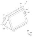
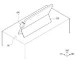
도 1a는 본 발명의 일 실시예에 따른 POS단말기의 사시도를 도시한 것이다.
도 1b는 도 1a에 도시된 POS단말기를 일 측에서 바라본 형상을 도시한 것이다.
도 1c는 도 1에 도시된 본체의 내부 부품들을 도시한 블럭도이다.
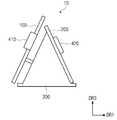
도 2a는 본 발명의 일 실시예에 따른 POS단말기의 제2 표시장치가 탈/부착 되는 것을 도시한 것이다.
도 2b는 본 발명의 일 실시예에 따른 본체의 제1 무선통신부와 제2 표시장치의 제2 무선통신부를 도시한 블럭도이다.
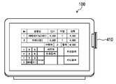
도 3a는 본 발명의 일 실시예에 따른 POS단말기의 제1 표시장치를 도시한 것이다.
도 3b는 본 발명의 일 실시예에 따른 POS단말기의 제2 표시장치를 도시한 것이다.
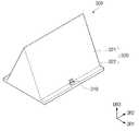
도 3c는 본 발명의 일 실시예에 따른 POS단말기의 본체를 도시한 것이다.
도 4는 본 발명의 일 실시예에 따른 POS단말기의 제2 표시장치의 뒷면을 도시한 것이다.
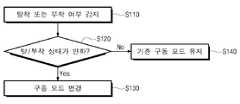
도 5는 제2 표시장치와 본체 간의 탈/부착 여부에 따라 POS단말기의 모드가 자동으로 변경되는 단계를 도시한 순서도이다.
도 6은 제2 표시장치와 본체 간의 탈/부착 여부에 따라 POS단말기의 모드가 수동으로 변경되는 단계를 도시한 순서도이다.
도 7a 및 도 7b는 제1 표시장치 또는 제2 표시장치에 표시되는 구동모드 선택 메시지를 도시한 것이다.
도 8, 도 9, 및 도 10은 본 발명의 일 실시예에 따른 POS단말기의 시용예를 도시한 것이다.
도 11, 도 12a, 및 도 12b는 본 발명의 일 실시예에 따른 본체의 고정부재를 도시한 것이다.1A is a perspective view of a POS terminal according to an embodiment of the present invention.
FIG. 1B shows a perspective view of the POS terminal shown in FIG. 1A.
1C is a block diagram illustrating the internal components of the body shown in FIG.
2A illustrates the second display device of the POS terminal being detached / attached according to an embodiment of the present invention.
2B is a block diagram illustrating a first wireless communication unit of a main body and a second wireless communication unit of a second display device according to an embodiment of the present invention.
FIG. 3A illustrates a first display device of a POS terminal according to an embodiment of the present invention.
FIG. 3B illustrates a second display device of a POS terminal according to an embodiment of the present invention.
3C illustrates a body of a POS terminal according to an embodiment of the present invention.
4 is a rear view of a second display device of a POS terminal according to an embodiment of the present invention.
5 is a flowchart showing a step of automatically changing the mode of the POS terminal according to whether or not the second display device is attached / detached between the second display device and the main body.
6 is a flowchart illustrating a step in which the mode of the POS terminal is manually changed according to whether or not the second display device is detached / attached to / from the main body.
7A and 7B show a drive mode selection message displayed on the first display device or the second display device.
8, 9, and 10 illustrate application examples of a POS terminal according to an embodiment of the present invention.
11, 12A, and 12B illustrate a fixing member of a main body according to an embodiment of the present invention.
본 발명은 다양한 변경을 가할 수 있고 여러 가지 형태를 가질 수 있는 바, 특정 실시예들을 도면에 예시하고 본문에 상세하게 설명하고자 한다. 그러나, 이는 본 발명을 특정한 개시 형태에 대해 한정하려는 것이 아니며, 본 발명의 사상 및 기술 범위에 포함되는 모든 변경, 균등물 내지 대체물을 포함하는 것으로 이해되어야 한다.The present invention is capable of various modifications and various forms, and specific embodiments are illustrated in the drawings and described in detail in the text. It should be understood, however, that the invention is not intended to be limited to the particular forms disclosed, but includes all modifications, equivalents, and alternatives falling within the spirit and scope of the invention.
각 도면을 설명하면서 유사한 참조부호를 유사한 구성요소에 대해 사용하였다. 첨부된 도면에 있어서, 구조물들의 치수는 본 발명의 명확성을 위하여 실제보다 확대 또는 축소하여 도시한 것이다.Like reference numerals are used for like elements in describing each drawing. In the attached drawings, the dimensions of the structures are shown enlarged or reduced in size for clarity of the present invention.
본 출원에서, "포함하다" 또는 "가지다" 등의 용어는 명세서 상에 기재된 특징, 숫자, 단계, 동작, 구성요소, 부품 또는 이들을 조합한 것이 존재함을 지정하려는 것이지, 하나 또는 그 이상의 다른 특징들이나 숫자, 단계, 동작, 구성요소, 부분품 또는 이들을 조합한 것들의 존재 또는 부가 가능성을 미리 배제하지 않는 것으로 이해되어야 한다.In the present application, the terms "comprises" or "having" and the like are used to specify that there is a feature, a number, a step, an operation, an element, a component or a combination thereof described in the specification, But do not preclude the presence or addition of one or more other features, integers, steps, operations, components, parts, or combinations thereof.
이하, 첨부한 도면들을 참조하여 본 발명의 바람직한 실시예를 보다 상세하게 설명하고자 한다.Hereinafter, preferred embodiments of the present invention will be described in detail with reference to the accompanying drawings.
도 1a는 본 발명의 일 실시예에 따른 POS단말기(10)의 사시도를 도시한 것이다. 도 1b는 도 1a에 도시된 POS단말기(10)를 일 측에서 바라본 형상을 도시한 것이다. 도 1c는 도 1에 도시된 본체(300)의 내부 부품들을 도시한 블럭도이다.1A is a perspective view of a
POS단말기(10)는 제1 표시장치(100), 제2 표시장치(200), 본체(300), 제1 카드 리더기(410), 및 제2 카드 리더기(420)를 포함한다.The
제1 표시장치(100) 및 제2 표시장치(200) 각각은 표시패널, 게이트 구동회로, 데이터 구동회로, 및 외부 커버 등을 포함 할 수 있다. 예를들어, 제1 표시장치(100) 및 제2 표시장치(200)은 액정 표시장치, 유기발광 표시장치, 또는 플라즈마 표시장치 중 어느 하나 일 수 있다.Each of the
제1 표시장치(100) 및 제2 표시장치(200) 각각은 외부의 터치를 감지할 수 있는 터치 감지 패널을 더 포함 할 수 있다. 제1 표시장치(100) 및 제2 표시장치(200)은 터치 감지 패널을 통해, 사용자가 선택한 터치 입력을 감지할 수 있다.Each of the
제1 표시장치(100) 및 제2 표시장치(200)은 본체(300)와 전기적 신호를 송/수신 할 수 있다. 표시장치들(100, 200)과 본체(300)가 전기적 신호를 송/수신 하기 위해서 유선통신 또는 무선 통신이 이용될 수 있다. 유선통신은, 예를들어, 케이블 또는 USB포트 등을 이용하는 방식일 수 있다. 무선통신은, 예를들어, 블루투스, 와이파이, 또는 IMT-2000 표준에 따른 디지털 휴대전화 방식일 수 있다.The
제1 표시장치(100) 및 제2 표시장치(200) 본체(300)로부터 수신한 신호에 대응하는 정보를 표시한다. 예를들어, 제1 표시장치(100) 및 제2 표시장치(200)가 표시하는 정보는 상품의 금액, 결제수단, 또는 수요자가 상품을 구매하기 위해 제공한 금액 등일 수 있다.Information corresponding to the signal received from the
본체(300)는 제1 표시장치(100) 또는 제2 표시장치(200)로부터 제공되는 신호를 기반으로 필요한 연산을 수행할 수 있다. 제1 표시장치(100) 또는 제2 표시장치(200)로부터 본체(300)쪽으로 제공되는 신호는 터치 감지 패널에 의해 감지되는 것으로, 예를들어, 사용자가 선택한 상품 또는 사용자가 선택한 결재수단 등에 대응하는 신호일 수 있다.The
본체(300)는 연산 처리 장치(1000), 그래픽 카드(2000), 메모리(3000), 및 메인보드(4000)를 포함할 수 있다.The
연산 처리 장치(1000, 또는 중앙처리장치)는 프로그램 명령어를 실행하는 일을 담당하며, 제어장치, 연산장치, 및 레지스터를 포함한다. 그리고 다른 장치들과는 시스템 버스로 연결된다. 제어장치는 프로그램 명령어를 해석하고, 해석된 명령의 의미에 따라 연산장치, 주기억장치, 입출력장치 등에게 동작을 지시한다. 연산장치는 덧셈, 뺄셈, 곱셈, 나눗셈의 산술 연산만이 아니라 AND, OR, NOT, XOR와 같은 논리 연산을 하는 장치로 제어장치의 지시에 따라 연산을 수행한다. 레지스터는 주기억장치로부터 읽어온 명령어나 데이터를 저장하거나 연산된 결과를 저장하는 공간이다.The arithmetic processing unit 1000 (or the central processing unit) is responsible for executing program instructions, and includes a control unit, a computing unit, and a register. It is connected to other devices by a system bus. The control device interprets the program instructions and instructs the operation device, main memory device, input / output device, etc. according to the meaning of the interpreted instruction. The arithmetic unit performs not only arithmetic operations of addition, subtraction, multiplication, and division but also logical operations such as AND, OR, NOT, and XOR, and performs operations according to the instructions of the control apparatus. A register is a space in which instructions or data read from main memory are stored or the result of operation is stored.
그래픽 카드(2000)는 영상 신호를 생성하여 표시장치들(100, 200)에 제공한다.The
그래픽 카드(2000)는 비디오칩, 비디오 메모리, DAC, 바이오스(BIOS)를 포함한다. 비디오칩은 연산처리를 수행한다. 비디오 메모리는 이미지를 생성하며, 비디오 메모리 양이 많을수록 모니터의 해상도가 높아진다. DAC(Digital Analog Converter)는 디지털 신호를 아날로그 신호로 바꿔주는 장치이다. 바이오스에는 비디오 어댑터의 정보와 기본적인 입출력을 알려주는 프로그램 루틴(routine)이 저장되어 있다.The
메모리(3000)는 RAM(random access memory), ROM(read only memory), 보조기억장치를 포함한다. RAM은 기록, 판독을 할 수 있는 기억장치이고, ROM은 판독 전용의 기억 장치이다. 보조기억장치는 HDD(Hard Disk Drive) 또는 SSD(Solid State Drive)일 수 있다. 보조기억장치에는 POS단말기(10)를 이용하여 판매하려는 상품들의 목록, 가격, 또는 잔여수량 등이 저정되어 있을 수 있다. The
메인보드(4000)는 POS단말기(10)의 실행 환경을 설정하고 그 정보를 유지해 주며, POS단말기(10)가 안정적으로 구동되게 해주고, POS단말기(10)의 모든 장치들의 데이터 입출력 교환을 원활하게 해주는 부분이다. 메인보드(4000)에 상기 기술한 연산 처리 장치(1000), 그래픽 카드(2000), 및 메모리(3000) 등이 결합될 수 있다.The
카드 리더기들(410, 420) 각각은 사용자의 신용카드 정보를 판독하여 상품의 금액을 결재하기 위한 단말기이다. 또한, 카드 리더기들(410, 420) 각각은 신용카드 정보외에 포인트 적립을 위한 포인트 카드 정보를 판독할 수 있다.Each of the
카드 리더기들(410, 420)은 각각 표시장치들(100, 200)의 일측에 배치될 수 있다. 제1 카드 리더기(410)는 제1 표시장치(100)의 일측에 배치되고, 제2 카드 리더기(420)는 제2 표시장치의 일측에 배치될 수 있다. 단, 제1 카드 리더기(410) 및 제2 카드 리더기(420)의 배치 위치가 이에 제한되는 것은 아니며, 본 발명의 다른 실시예에서, 카드 리더기들(410, 420)은 표시장치들(100, 200)과 분리되어 배치될 수 있다.The
제1 카드 리더기(410)는 제1 표시장치(100)에서 제공하는 정보에 대응하는 금액을 계산할 수 있다. 제2 카드 리더기(420)는 제2 표시장치(200)에서 제공하는 정보에 대응하는 금액을 계산할 수 있다.The
도 2a는 POS단말기(10)의 제2 표시장치(200)가 탈/부착 되는 것을 도시한 것이다. 제2 표시장치(200)는 본체(300)와 용이하게 탈/부착 될 수 있다. 도 2b는 본 발명의 일 실시예에 따른 본체(300)의 제1 무선통신부(WL1)와 제2 표시장치(200)의 제2 무선통신부(WL2)를 도시한 블럭도이다.2A shows the
제2 표시장치(200)는 입력단자(210)를 포함하고, 본체(300)는 출력단자(310)을 포함할 수 있다. 입력단자(210)와 출력단자(310)는 서로 대응되는 구성으로, 이들의 결합에 의해 본체(300)와 제2 표시장치(200)는 서로 전기적 신호를 송/수신할 수 있다.The
제2 표시장치(200)는 내장 배터리(미도시)를 포함한다. 내장 배터리는 제2 표시장치(200)가 본체(300)로부터 분리되더라도 구동될 수 있도록 파워를 제공한다. 입력단자(210)와 출력단자(310)가 결합되어 있는 동안, 제2 표시장치(200)의 내장 배터리는 본체(300)로부터 제공된 전력에 의해 충전될 수 있다. 이 때, 본체(300)는 외부의 전기 콘센트로부터 전력을 공급 받는다.The
예를들어, 본체(300)의 출력단자(310)는 micro USB 5핀의 숫단자이고, 제2 표시장치(200)의 입력단자(210)는 micro USB 5핀의 암단자 일 수 있다. 단, 이에 제한되지 않으며, 출력단자(310)와 입력단자(210)는 각각 전기적 신호를 송/수신하고, 전력을 전달할 수 있는 단자들일 수 있다.For example, the
도 2b를 참조하면, 본체(300)는 제1 무선통신부(WL1)를 포함하고, 제2 표시장치(200)는 제2 무선통신부(WL2)를 포함할 수 있다. 제2 표시장치(200)가 본체(300)로부터 탈착되는 경우, 제1 무선통신부(WL1)와 제2 무선통신부(WL2)를 통해 본체(300)와 제2 표시장치(200)는 정보를 송/수신 할 수 있다. 제1 무선통신부(WL1)와 제2 무선통신부(WL2)가 정보를 송/수신 하는 방법은, 예를들어, 블루투스, 블루투스, 와이파이, 또는 IMT-2000 표준에 따른 디지털 휴대전화 방식일 수 있다.Referring to FIG. 2B, the
도 1a, 도 1b, 및 도 2a에 도시된 것과 같이, POS단말기(10)는 본체(300)와 제2 표시장치(200)가 부착되어 있는 모드(이하, 부착 모드)와 본체(300)와 제2 표시장치(200)가 탈착되어 있는 모드(이하, 탈착 모드)를 포함할 수 있다.The
도 3a는 본 발명의 일 실시예에 따른 POS단말기(10)의 제1 표시장치(100)를 도시한 것이다. 도 3b는 본 발명의 일 실시예에 따른 POS단말기(10)의 제2 표시장치(200)를 도시한 것이다. 도 3c는 본 발명의 일 실시예에 따른 POS단말기의 본체(300)를 도시한 것이다.FIG. 3A shows a
제1 표시장치(100)는 사용자에게 제1 정보화면(DT1)을 제공할 수 있다. 제2 표시장치(200)는 다른 사용자에게 제2 정보화면(DT2)을 제공할 수 있다. 제1 정보화면(DT1) 및 제2 정보화면(DT2)은 각각 매장에서 판매하는 상품, 단가, 수량, 또는 상품을 구매하려는 사람이 사용하는 결재수단 중 적어도 어느 하나에 대한 정보를 제공한다.The
제1 정보화면(DT1) 및 제2 정보화면(DT2) 서로 종속하여 실질적으로 동일한 정보를 사용자들에게 제공할 수 있다. 본 발명의 다른 실시예에서는 제1 정보화면(DT1) 및 제2 정보화면(DT2)은 서로 독립적으로 사용자들에게 다른 정보를 제공할 수 있다.The first information screen DT1 and the second information screen DT2 can be subordinate to each other to provide substantially the same information to the users. In another embodiment of the present invention, the first information screen DT1 and the second information screen DT2 may provide different information to users independently of each other.
본체(300)는 고정부재(320)를 포함할 수 있다. 고정부재(320)는 지지부(321)와 받침부(322)를 포함할 수 있다. 지지부(321)는 제2 표시장치(200)의 뒷면와 접촉하여 제2 표시장치(200)가 넘어지지 않게 한다. 받침부(322)는 제2 표시장치(200)의 아랫쪽면과 접촉하여 제2 표시장치(200)가 미끄러지지 않게 한다. 이와 같이 지지부(321)와 받침부(322)의 조합에 의해 제2 표시장치(200)는 본체(300)에 고정될 수 있다. 단, 이에 제한되는 것은 아니며, 본체(300)는 제2 표시장치(200)를 고정하기 위한 추가적인 부재를 더 포함할 수 있다. 또한, 본체(300)는 제2 표시장치(200)를 고정하기 위한 다른 형상의 고정부재를 가질 수 있다.The
도 4는 본 발명의 일 실시예에 따른 POS단말기(10)의 제2 표시장치(200)의 뒷면을 도시한 것이다.4 illustrates a rear view of a
제2 표시장치(200)는 스탠딩 부재(220)를 포함할 수 있다. 제2 표시장치(200)는 스탠딩 부재(220)을 통해 지지면(SS)에 세워질 수 있다.The
스탠딩 부재(220)는 제2 표시장치(200)의 백 커버로부터 접히거나 펼쳐질 수 있다. 제2 표시장치(200)가 본체(300)에 결합되어 있는 경우, 스탠딩 부재(220)는 제2 표시장치(200)의 백 커버 쪽으로 접힐 수 있다. 반면, 제2 표시장치(200)가 본체(300)로부터 펼쳐지는 경우, 스탠딩 부재(220)는 제2 표시장치(200)의 백 커버로부터 펼쳐져서, 제2 표시장치(200)가 단독적으로 지지면(SS)에 세워질 수 있다. 단, 스탠딩 부재(220)의 형상은 이제 제한되지 않으며, 제2 표시장치(200)를 지지면(SS)에 세울 수 있는 다른 형상을 가질 수 있다.The standing
본 발명의 다른 실시예에서, 제2 표시장치(200)는 스탠딩 부재(220)를 포함하지 않을 수 있다. 이 경우, 제2 표시장치(200)는 별도의 지지부재에 의해 지지면(SS)에 세워질 수 있다.In another embodiment of the present invention, the
도 5는 제2 표시장치(200)와 본체(300) 간의 탈/부착 여부에 따라 POS단말기(10)의 모드가 자동으로 변경되는 단계를 도시한 순서도이다. 도 6은 제2 표시장치(200)와 본체(300)간의 탈/부착 여부에 따라 POS단말기(10)의 모드가 수동으로 변경되는 단계를 도시한 순서도이다. 도 7a 및 도 7b는 제1 표시장치(100) 또는 제2 표시장치(200)에 표시되는 구동모드 선택 메시지를 도시한 것이다.5 is a flowchart showing a step in which the mode of the
POS단말기(10)의 구동모드는 종속적 구동모드와 독립적 구동모드를 포함한다. 종속적 구동모드에서, 제1 표시장치(100)와 제2 표시장치(200)를 하나의 시스템처럼 실질적으로 동일한 정보를 표시한다. 독립적 구동모드에서 제1 표시장치(100)와 제2 표시장치(200)는 각각 별개의 시스템처럼 서로 다른 정보를 표시한다. 본 발명의 일 실시예에 따른 POS단말기(10)는 부착 모드에서는 종속적 구동모드로 작동하고, 탈착 모드에서는 독립적 구동모드로 작동할 수 있다.The driving mode of the
도 2a 및 도 5를 참조하면, 감지 단계(S110)에서 제2 표시장치(200)와 본체(300)가 서로 탈착 또는 부착 될 때, POS단말기(10)의 본체(300) 또는 제2 표시장치(200)는 탈착 모드와 부착 모드 간의 모드 전환을 감지한다.2A and FIG. 5, when the
탈/부착 판단 단계(S120)에서 탈착 모드와 부착 모드 간의 모드 변환이 된 것으로 판단된 경우, POS단말기(10)는 자신의 구동모드를 변경(S130)한다. 탈/부착 판단 단계(S120)에서 탈착 모드와 부착 모드 간의 모드 변환이 되지 않은 것으로 판단된 경우, POS단말기(10)는 자신의 기존 구동모드를 유지(S140)한다.If it is determined in step S120 that the mode conversion between the detachable mode and the attached mode has been performed, the
도 2a 및 도 6을 참조하면, 감지 단계(S210)에서 제2 표시장치(200)와 본체(300)가 서로 탈착 또는 부착 될 때, POS단말기(10)의 본체(300) 또는 제2 표시장치(200)는 탈착 모드와 부착 모드 간의 모드 전환을 감지한다.2A and FIG. 6, when the
탈/부착 판단 단계(S220)에서 탈착 모드와 부착 모드 간의 모드 변환이 된 것으로 판단된 경우, POS단말기(10)는 제1 표시장치(100) 또는 제2 표시장치(200) 중 적어도 어느 하나에 구동모드 선택화면을 실행(S230)한다. 탈/부착 판단 단계(S220)에서 탈착 모드와 부착 모드 간의 모드 변환이 되지 않은 것으로 판단된 경우, POS단말기(10)는 자신의 기존 구동모드를 유지(S260)한다.If it is determined in step S220 that the mode conversion between the detachment mode and the attaching mode has been performed, the
구동모드 선택단계(S240)에서, 제1 표시장치(100) 또는 제2 표시장치(200) 중 적어도 어느 하나에는 도 7a 및 도 7b에 도시된 것과 같은 구동모드 선택 메시지들(MS1, MS2)이 표시되고, 사용자는 이를 통해서 구동모드를 전환하거나 기존의 구동모드를 유지할 수 있다.In at least one of the
구동모드 선택단계(S240)에서 사용자가 구동모드 전환을 선택하는 경우, POS단말기(10)는 자신의 기존 구동모드를 변경(S250)한다. 구동모드 선택단계(S240)에서 사용자가 구동모드 전환을 하지 않는 경우, POS단말기(10)는 자신의 기존 구동모드를 유지(S260)한다.In the drive mode selection step S240, when the user selects the drive mode change, the
도 7a를 참조하면, 제1 구동모드 선택 메시지(MS1)는 부착 모드에서 탈착 모드로 변경되는 경우, 제1 표시장치(100) 또는 제2 표시장치(200) 중 적어도 어느 하나에 표시되는 메시지이다.Referring to FIG. 7A, the first drive mode selection message MS1 is a message displayed on at least one of the
도 7b를 참조하면 제2 구동모드 선택 메시지(MS2)는 탈착 모드에서 부착 모드로 변경되는 경우, 제1 표시장치(100) 또는 제2 표시장치(200) 중 적어도 어느 하나에 표시되는 메시지이다.Referring to FIG. 7B, the second drive mode selection message MS2 is a message displayed on at least one of the
단, POS단말기(10)의 구동모드 변경방법은 이에 제한되지 않으며, POS단말기(10)의 설정모드를 통해, 탈착 모드와 부착 모드 간의 모드전환에 관계없이, 구동모드를 변경할 수 있다.However, the method of changing the driving mode of the
도 8, 도9, 및 도 10은 본 발명의 일 실시예에 따른 POS단말기(10)의 사용예를 도시한 것이다.8, 9, and 10 illustrate examples of use of the
도 8은 POS단말기(10)가 부착 모드 및 종속적 구동모드에서 사용되는 예를 도시한 것이다. 부착 모드 및 종속적 구동모드의 경우, 제1 표시장치(100)는 종업원(CSH)에게 정보를 제공하고, 제2 표시장치(200)는 손님들(CT1, CT2)에게 정보를 제공할 수 있다. 이때, 종업원(CSH)는 손님들(CT1, CT2)의 주문을 받아 제1 표시장치(100)를 통해 해당 내용을 입력할 수 있고, 손님들(CT1, CT2)은 제2 표시장치(200)를 통해 자신들이 주문한 상품들이 올바르게 입력되었는지 확인할 수 있다.Fig. 8 shows an example in which the
도 9는 POS단말기(10)기 부착 모드 및 독립적 구동모드에서 사용되는 예를 도시한 것이다. 부착 모드 및 독립적 구동모드에서 제1 표시장치(100) 및 제2 표시장치(200)는 각각 손님들(CT1, CT2, CT3, CT4)에게 정보를 제공하고, 손님들(CT1, CT2, CT3, CT4)의 입력을 감지할 수 있다.Fig. 9 shows an example in which the
예를들어, 제1 손님(CT1)과 제2 손님(CT2)은 제2 표시장치(200)를 통해 원하는 상품을 선택하고, 자신이 주문한 상품들이 올바르게 입력되었는지 확인할 수 있다. 또한, 제1 손님(CT1)과 제2 손님(CT2)은 제2 카드 리더기(420)를 통해 신용카드 또는 체크카드를 이용한 결제 및 포인트 적립 카드를 이용한 포인트 적립을 수행할 수 있다.For example, the first guest CT1 and the second guest CT2 can select a desired commodity through the
제3 손님(CT3)과 제4 손님(CT4)은 제1 표시장치(100)를 통해 원하는 상품을 선택하고, 자신이 주문한 상품들이 올바르게 입력되었는지 확인할 수 있다. 또한, 제3 손님(CT3)과 제4 손님(CT4)은 제1 카드 리더기(410)를 통해 신용카드 또는 체크카드를 이용한 결제 및 포인트 적립 카드를 이용한 포인트 적립을 수행할 수 있다.The third guest CT3 and the fourth guest CT4 can select a desired commodity through the
부착 모드 및 독립적 구동모드에서는 계산을 도와주는 별도의 종업원이 없더라도, 손님들(CT1, CT2, CT3, CT4)들이 스스로 상품 주문 및 결제를 할 수 있으므로, 주문 시간을 줄일 수 있다. 또한, 사업주 입장에서는 종업원 고용에 필요한 인건비 등을 절감할 수 있다.In the attachment mode and the independent drive mode, the customers (CT1, CT2, CT3, CT4) can order goods and pay for themselves even though there is no separate employee to assist in the calculation. Also, from the viewpoint of employers, it is possible to reduce the personnel expenses required for hiring employees.
도 10은 POS단말기(10)기 탈착 모드 및 독립적 구동모드에서 사용되는 예를 도시한 것이다. 탈착 모드 및 독립적 구동모드에서 제2 표시장치(200)는 제1 표시장치(100) 및 본체(300)로부터 이격되어 사용될 수 있다.Fig. 10 shows an example in which the
탈착 모드 및 독립적 구동모드에서, 제2 표시장치(200)는 사업장의 구조 및 편의에 따라 자유롭게 배치가 가능하므로, POS단말기(10)를 탄력적으로 응용하여 사용할 수 있다. 그 외, 손님들이 POS단말기(10)를 사용하는 방법 및 효과는 도 9에서 설명한 것과 실질적으로 동일한바 생략한다.In the detachable mode and the independent driving mode, the
도 11, 도 12a, 및 도 12b는 본 발명의 일 실시예에 따른 본체(300)의 고정부재(320-1, 320-2)를 도시한 것이다. 도 11, 도 12a, 및 도 12b에서, 설명의 편의상 POS단말기(10)의 제1 표시장치(100) 및 본체(300) 중 일부는 도시하지 않았다.11, 12A, and 12B illustrate fixing members 320-1 and 320-2 of the
도 11을 참조하면, 고정부재(320-1)는 제2 표시장치(200)의 윗면과 아랫면을 지지하여, 제2 표시장치(200)가 본체(300)에 부착되도록 할 수 있다. 고정부재(320-1)은 제3 방향(DR3)으로 길이가 조절되며, 이와 같은 길이 조절을 통해 제2 표시장치(200)가 고정부재(320-1)에 단단하게 결합될 수 있다.11, the fixing member 320-1 supports the upper surface and the lower surface of the
도 12a 및 도 12b를 참조하면, 고정부재(320-2)는 제2 표시장치(200)의 윗면, 아랫면, 및 측면 에워싸도록 지지하여, 제2 표시장치(200)가 본체(300)에 부착되도록 할 수 있다. 도 12a와 같이 고정부재(320-2)를 조절하여 제2 표시장치(200)를 올려놓을 수 있을 정도의 충분한 공간을 확보한다. 그 후, 도 12b와 같이 고정부재(320-2)를 조절하여 제2 표시장치(200)가 고정부재(320-2)에 단단하게 결합되도록 할 수 있다.12A and 12B, the fixing member 320-2 supports the upper surface, the lower surface, and the side surfaces of the
이상 실시 예를 참조하여 설명하였지만, 해당 기술 분야의 숙련된 당업자는 하기의 특허 청구의 범위에 기재된 본 발명의 사상 및 영역으로부터 벗어나지 않는 범위 내에서 본 발명을 다양하게 수정 및 변경시킬 수 있음을 이해할 수 있을 것이다. 또한 본 발명에 개시된 실시 예는 본 발명의 기술 사상을 한정하기 위한 것이 아니고, 하기의 특허 청구의 범위 및 그와 동등한 범위 내에 있는 모든 기술 사상은 본 발명의 권리범위에 포함되는 것으로 해석되어야 할 것이다.It will be understood by those skilled in the art that various changes in form and details may be made therein without departing from the spirit and scope of the invention as defined in the appended claims. It will be possible. In addition, the embodiments disclosed in the present invention are not intended to limit the technical spirit of the present invention, and all technical ideas which fall within the scope of the following claims and equivalents thereof should be interpreted as being included in the scope of the present invention .
10: POS단말기100: 제1 표시장치
200: 제2 표시장치300: 본체
410, 420: 카드 리더기10: POS terminal 100: First display device
200: second display device 300:
410, 420: Card reader
Claims (15)
Translated fromKorean상기 제1 표시장치는 상기 본체와 결합되어, 상기 본체로부터 수신한 신호에 대응한 정보를 제공하고,
상기 제2 표시장치는 상기 본체와 탈/부착이 용이하게 결합되어, 상기 본체로부터 수신한 신호에 대응한 정보를 제공하며,
상기 본체는 상기 제1 표시장치와 상기 제2 표시장치를 제어하고,
상기 제2 표시장치는 지지면(supporting surface)에 세울 때 이용되며 상기 제2 표시장치의 백 커버로부터 접히고 펼쳐질 수 있는 스탠딩 부재를 포함하고,
상기 제2 표시장치와 상기 본체가 탈착된 상태인 탈착 모드 및 상기 제2 표시장치와 상기 본체가 부착된 상태인 부착 모드를 포함하며,
상기 제1 표시장치 및 상기 제2 표시장치가 실질적으로 동일한 정보를 표시하며 종속적으로 구동하는 종속적 구동모드 및 상기 제1 표시장치 및 상기 제2 표시장치가 서로 다른 정보를 표시하며 독립적으로 구동하는 독립적 구동모드를 포함하고,
상기 탈착 모드 및 상기 부착 모드 간의 모드 전환이 발생할 때,
상기 제1 표시장치 및 상기 제2 표시장치 중 적어도 어느 하나에는 상기 종속적 구동모드 또는 상기 독립적 구동모드 중 어느 하나를 선택할 수 있는 화면이 표시되는 POS단말기.A POS terminal including a first display device, a second display device, and a main body,
Wherein the first display device is coupled to the main body and provides information corresponding to a signal received from the main body,
The second display device is easily coupled with the main body so as to provide information corresponding to the signal received from the main body,
Wherein the main body controls the first display device and the second display device,
Wherein the second display device comprises a standing member which is used when standing on a supporting surface and can be folded and unfolded from the back cover of the second display device,
A detachment mode in which the second display device and the main body are detached, and an attachment mode in which the second display device and the main body are attached,
Wherein the first display device and the second display device display substantially the same information and are driven in a dependent manner, and the first display device and the second display device display different information and are independently driven Drive mode,
When a mode switching between the detachment mode and the attachment mode occurs,
Wherein at least one of the first display device and the second display device displays a screen capable of selecting either the dependent drive mode or the independent drive mode.
상기 제1 표시장치 및 상기 제2 표시장치 각각은 터치감지 패널을 포함하는 POS단말기.The method according to claim 1,
Wherein each of the first display device and the second display device includes a touch sensing panel.
상기 제1 표시장치에서 제공하는 정보에 대응하는 금액을 계산할 수 있는 제1 카드 리더기를 더 포함하는 POS단말기.3. The method of claim 2,
Further comprising: a first card reader capable of calculating an amount corresponding to information provided by said first display device.
상기 제2 표시장치에 제공하는 정보에 대응하는 금액을 계산할 수 있는 제2 카드 리더기를 더 포함하는 POS단말기.The method of claim 3,
And a second card reader capable of calculating an amount corresponding to information provided to the second display device.
상기 본체는 출력단자를 포함하고, 상기 제2 표시장치는 상기 출력단자에 대응하는 입력단자를 포함하며,
상기 출력단자와 상기 입력단자가 결합될 때, 상기 본체는 상기 제2 표시장치에 전기적 신호를 제공하는 POS단말기.3. The method of claim 2,
The main body includes an output terminal, and the second display device includes an input terminal corresponding to the output terminal,
And the body provides an electrical signal to the second display device when the output terminal and the input terminal are coupled.
상기 제2 표시장치는 내장 배터리를 포함하고,
상기 출력단자와 상기 입력단자의 결합에 의해 상기 내장 배터리가 충전되는 POS단말기.6. The method of claim 5,
Wherein the second display device includes a built-in battery,
And the built-in battery is charged by coupling the output terminal and the input terminal.
상기 본체는 제1 무선통신부를 포함하고, 상기 제2 표시장치는 제2 무선통신부를 포함하며,
상기 탈착 모드에서, 상기 본체와 상기 제2 표시장치는 상기 제1 무선통신부와 상기 제2 무선통신부를 통해 정보를 송/수신하는 POS단말기.The method according to claim 1,
Wherein the main body includes a first wireless communication unit and the second display unit includes a second wireless communication unit,
In the removable mode, the main body and the second display device transmit / receive information through the first wireless communication unit and the second wireless communication unit.
Priority Applications (1)
| Application Number | Priority Date | Filing Date | Title |
|---|---|---|---|
| KR1020160010768AKR101799875B1 (en) | 2016-01-28 | 2016-01-28 | Pos terminal |
Applications Claiming Priority (1)
| Application Number | Priority Date | Filing Date | Title |
|---|---|---|---|
| KR1020160010768AKR101799875B1 (en) | 2016-01-28 | 2016-01-28 | Pos terminal |
Publications (2)
| Publication Number | Publication Date |
|---|---|
| KR20170090201A KR20170090201A (en) | 2017-08-07 |
| KR101799875B1true KR101799875B1 (en) | 2017-11-22 |
Family
ID=59653767
Family Applications (1)
| Application Number | Title | Priority Date | Filing Date |
|---|---|---|---|
| KR1020160010768AExpired - Fee RelatedKR101799875B1 (en) | 2016-01-28 | 2016-01-28 | Pos terminal |
Country Status (1)
| Country | Link |
|---|---|
| KR (1) | KR101799875B1 (en) |
Cited By (3)
| Publication number | Priority date | Publication date | Assignee | Title |
|---|---|---|---|---|
| EP4202814A1 (en) | 2021-12-21 | 2023-06-28 | Hee Young Park | Card payment method and system through application linkage |
| KR20230107462A (en) | 2022-01-07 | 2023-07-17 | 박희영 | Card payment method and system through application linkage |
| KR20240161046A (en) | 2022-01-07 | 2024-11-12 | 박희영 | Card payment method and system through application linkage |
Families Citing this family (4)
| Publication number | Priority date | Publication date | Assignee | Title |
|---|---|---|---|---|
| US9704355B2 (en) | 2014-10-29 | 2017-07-11 | Clover Network, Inc. | Secure point of sale terminal and associated methods |
| JP7145380B2 (en) | 2018-03-19 | 2022-10-03 | 日本電気株式会社 | Information processing device, information processing method and program |
| US10657505B2 (en) | 2018-07-26 | 2020-05-19 | Clover Network, Inc. | Dual mode payment and display system |
| US11232440B2 (en) | 2019-10-29 | 2022-01-25 | Clover Network, Llc | Dual device point of sale system using short-range wireless connection |
Citations (3)
| Publication number | Priority date | Publication date | Assignee | Title |
|---|---|---|---|---|
| KR200407834Y1 (en)* | 2005-11-02 | 2006-02-03 | 밸크리텍주식회사 | POS terminal |
| JP2014041559A (en)* | 2012-08-23 | 2014-03-06 | Teraoka Seiko Co Ltd | Post register |
| KR200477766Y1 (en) | 2014-01-16 | 2015-07-22 | 하나시스 주식회사 | Pos apparatus |
- 2016
- 2016-01-28KRKR1020160010768Apatent/KR101799875B1/ennot_activeExpired - Fee Related
Patent Citations (3)
| Publication number | Priority date | Publication date | Assignee | Title |
|---|---|---|---|---|
| KR200407834Y1 (en)* | 2005-11-02 | 2006-02-03 | 밸크리텍주식회사 | POS terminal |
| JP2014041559A (en)* | 2012-08-23 | 2014-03-06 | Teraoka Seiko Co Ltd | Post register |
| KR200477766Y1 (en) | 2014-01-16 | 2015-07-22 | 하나시스 주식회사 | Pos apparatus |
Cited By (3)
| Publication number | Priority date | Publication date | Assignee | Title |
|---|---|---|---|---|
| EP4202814A1 (en) | 2021-12-21 | 2023-06-28 | Hee Young Park | Card payment method and system through application linkage |
| KR20230107462A (en) | 2022-01-07 | 2023-07-17 | 박희영 | Card payment method and system through application linkage |
| KR20240161046A (en) | 2022-01-07 | 2024-11-12 | 박희영 | Card payment method and system through application linkage |
Also Published As
| Publication number | Publication date |
|---|---|
| KR20170090201A (en) | 2017-08-07 |
Similar Documents
| Publication | Publication Date | Title |
|---|---|---|
| KR101799875B1 (en) | Pos terminal | |
| US9881292B2 (en) | Point of sale (POS) docking station system and method for a mobile barcode scanner gun system with mobile tablet device or stand alone mobile tablet device | |
| EP2645343B1 (en) | POS terminal and POS system using mobile terminal | |
| US10339515B1 (en) | Shopping cart with integrated scale and point of sale device | |
| JP4789650B2 (en) | Electronic shelf label system and electronic shelf label | |
| US20190228374A1 (en) | Mobile Tablet Gun System With Mobile Tablet Having A Mobile POS And Enterprise Resource Planning Application For Pos Customer Order Fulfillment And In-store Inventory Management For Retail Establishment | |
| JP7513150B2 (en) | Information processing system, information processing method, and program | |
| JP6273770B2 (en) | Product registration apparatus and accounting system provided with the product registration apparatus | |
| CN106570692A (en) | Self-service intelligent shopping system and method | |
| JP7630030B2 (en) | Programs and mobile devices | |
| US8393538B2 (en) | Self checkout terminal and control method of the same | |
| KR102756203B1 (en) | Information processing terminal device and program | |
| JP5386530B2 (en) | Order station and order receiving device | |
| JP6369006B2 (en) | Product registration system, accounting system, weighing device | |
| US20180137491A1 (en) | Host devices with e-paper displays | |
| JP2009053742A (en) | Electronic shelf label, electronic shelf label system and electronic shelf label display program | |
| JP6264835B2 (en) | Weighing device and weighing system | |
| JP2008203944A (en) | Electronic tag system | |
| US20210027267A1 (en) | Information processing device, information processing method, and storage medium | |
| JP2007319522A (en) | Electronic shelf label and electronic shelf label system | |
| KR20170106118A (en) | System and method for supporting self checkout monitoring | |
| JP6445950B2 (en) | Product sales system, ordering method and ordering program | |
| JP5427906B2 (en) | Electronics | |
| JP6517119B2 (en) | Product sales system and product sales method | |
| JP2019032907A (en) | Product sales system, ordering method and ordering program |
Legal Events
| Date | Code | Title | Description |
|---|---|---|---|
| A201 | Request for examination | ||
| PA0109 | Patent application | St.27 status event code:A-0-1-A10-A12-nap-PA0109 | |
| PA0201 | Request for examination | St.27 status event code:A-1-2-D10-D11-exm-PA0201 | |
| D13-X000 | Search requested | St.27 status event code:A-1-2-D10-D13-srh-X000 | |
| D14-X000 | Search report completed | St.27 status event code:A-1-2-D10-D14-srh-X000 | |
| E902 | Notification of reason for refusal | ||
| PE0902 | Notice of grounds for rejection | St.27 status event code:A-1-2-D10-D21-exm-PE0902 | |
| T11-X000 | Administrative time limit extension requested | St.27 status event code:U-3-3-T10-T11-oth-X000 | |
| T11-X000 | Administrative time limit extension requested | St.27 status event code:U-3-3-T10-T11-oth-X000 | |
| AMND | Amendment | ||
| E13-X000 | Pre-grant limitation requested | St.27 status event code:A-2-3-E10-E13-lim-X000 | |
| P11-X000 | Amendment of application requested | St.27 status event code:A-2-2-P10-P11-nap-X000 | |
| P13-X000 | Application amended | St.27 status event code:A-2-2-P10-P13-nap-X000 | |
| PG1501 | Laying open of application | St.27 status event code:A-1-1-Q10-Q12-nap-PG1501 | |
| E601 | Decision to refuse application | ||
| PE0601 | Decision on rejection of patent | St.27 status event code:N-2-6-B10-B15-exm-PE0601 | |
| AMND | Amendment | ||
| E13-X000 | Pre-grant limitation requested | St.27 status event code:A-2-3-E10-E13-lim-X000 | |
| P11-X000 | Amendment of application requested | St.27 status event code:A-2-2-P10-P11-nap-X000 | |
| P13-X000 | Application amended | St.27 status event code:A-2-2-P10-P13-nap-X000 | |
| PX0901 | Re-examination | St.27 status event code:A-2-3-E10-E12-rex-PX0901 | |
| PX0701 | Decision of registration after re-examination | St.27 status event code:A-3-4-F10-F13-rex-PX0701 | |
| X701 | Decision to grant (after re-examination) | ||
| PR0701 | Registration of establishment | St.27 status event code:A-2-4-F10-F11-exm-PR0701 | |
| PR1002 | Payment of registration fee | St.27 status event code:A-2-2-U10-U11-oth-PR1002 Fee payment year number:1 | |
| PG1601 | Publication of registration | St.27 status event code:A-4-4-Q10-Q13-nap-PG1601 | |
| R18-X000 | Changes to party contact information recorded | St.27 status event code:A-5-5-R10-R18-oth-X000 | |
| R18-X000 | Changes to party contact information recorded | St.27 status event code:A-5-5-R10-R18-oth-X000 | |
| R18-X000 | Changes to party contact information recorded | St.27 status event code:A-5-5-R10-R18-oth-X000 | |
| P14-X000 | Amendment of ip right document requested | St.27 status event code:A-5-5-P10-P14-nap-X000 | |
| P16-X000 | Ip right document amended | St.27 status event code:A-5-5-P10-P16-nap-X000 | |
| Q16-X000 | A copy of ip right certificate issued | St.27 status event code:A-4-4-Q10-Q16-nap-X000 | |
| P14-X000 | Amendment of ip right document requested | St.27 status event code:A-5-5-P10-P14-nap-X000 | |
| R15-X000 | Change to inventor requested | St.27 status event code:A-5-5-R10-R15-oth-X000 | |
| P16-X000 | Ip right document amended | St.27 status event code:A-5-5-P10-P16-nap-X000 | |
| Q16-X000 | A copy of ip right certificate issued | St.27 status event code:A-4-4-Q10-Q16-nap-X000 | |
| R16-X000 | Change to inventor recorded | St.27 status event code:A-5-5-R10-R16-oth-X000 | |
| G170 | Re-publication after modification of scope of protection [patent] | ||
| PG1701 | Publication of correction | St.27 status event code:A-5-5-P10-P19-oth-PG1701 Patent document republication publication date:20200716 Republication note text:Request for Correction Notice (Document Request) Gazette number:1017998750000 Gazette reference publication date:20171122 | |
| PR1001 | Payment of annual fee | St.27 status event code:A-4-4-U10-U11-oth-PR1001 Fee payment year number:4 | |
| PR1001 | Payment of annual fee | St.27 status event code:A-4-4-U10-U11-oth-PR1001 Fee payment year number:5 | |
| PC1903 | Unpaid annual fee | St.27 status event code:A-4-4-U10-U13-oth-PC1903 Not in force date:20221116 Payment event data comment text:Termination Category : DEFAULT_OF_REGISTRATION_FEE | |
| PC1903 | Unpaid annual fee | St.27 status event code:N-4-6-H10-H13-oth-PC1903 Ip right cessation event data comment text:Termination Category : DEFAULT_OF_REGISTRATION_FEE Not in force date:20221116 |