KR101798899B1 - Nozzle fixing bracket of 3D-printer - Google Patents
Nozzle fixing bracket of 3D-printerDownload PDFInfo
- Publication number
- KR101798899B1 KR101798899B1KR1020160114741AKR20160114741AKR101798899B1KR 101798899 B1KR101798899 B1KR 101798899B1KR 1020160114741 AKR1020160114741 AKR 1020160114741AKR 20160114741 AKR20160114741 AKR 20160114741AKR 101798899 B1KR101798899 B1KR 101798899B1
- Authority
- KR
- South Korea
- Prior art keywords
- bracket
- printer
- axis shaft
- fastening
- fixing
- Prior art date
- Legal status (The legal status is an assumption and is not a legal conclusion. Google has not performed a legal analysis and makes no representation as to the accuracy of the status listed.)
- Active
Links
- 238000000034methodMethods0.000claimsdescription12
- 238000001816coolingMethods0.000claimsdescription7
- 125000006850spacer groupChemical group0.000claimsdescription3
- 238000009434installationMethods0.000claimsdescription2
- 238000010276constructionMethods0.000abstractdescription4
- 238000004519manufacturing processMethods0.000description7
- 229920005989resinPolymers0.000description3
- 239000011347resinSubstances0.000description3
- 238000000465mouldingMethods0.000description2
- 230000000149penetrating effectEffects0.000description2
- 238000000110selective laser sinteringMethods0.000description2
- 230000008021depositionEffects0.000description1
- 229920001002functional polymerPolymers0.000description1
- 238000003780insertionMethods0.000description1
- 230000037431insertionEffects0.000description1
- 238000003475laminationMethods0.000description1
- 230000013011matingEffects0.000description1
- 239000002184metalSubstances0.000description1
- 239000007769metal materialSubstances0.000description1
- 238000000016photochemical curingMethods0.000description1
- 239000000843powderSubstances0.000description1
- 238000007711solidificationMethods0.000description1
- 230000008023solidificationEffects0.000description1
- 229920001169thermoplasticPolymers0.000description1
- 229920005992thermoplastic resinPolymers0.000description1
Images


Classifications
- B—PERFORMING OPERATIONS; TRANSPORTING
- B29—WORKING OF PLASTICS; WORKING OF SUBSTANCES IN A PLASTIC STATE IN GENERAL
- B29C—SHAPING OR JOINING OF PLASTICS; SHAPING OF MATERIAL IN A PLASTIC STATE, NOT OTHERWISE PROVIDED FOR; AFTER-TREATMENT OF THE SHAPED PRODUCTS, e.g. REPAIRING
- B29C64/00—Additive manufacturing, i.e. manufacturing of three-dimensional [3D] objects by additive deposition, additive agglomeration or additive layering, e.g. by 3D printing, stereolithography or selective laser sintering
- B29C64/20—Apparatus for additive manufacturing; Details thereof or accessories therefor
- B29C64/205—Means for applying layers
- B29C64/209—Heads; Nozzles
- B—PERFORMING OPERATIONS; TRANSPORTING
- B29—WORKING OF PLASTICS; WORKING OF SUBSTANCES IN A PLASTIC STATE IN GENERAL
- B29C—SHAPING OR JOINING OF PLASTICS; SHAPING OF MATERIAL IN A PLASTIC STATE, NOT OTHERWISE PROVIDED FOR; AFTER-TREATMENT OF THE SHAPED PRODUCTS, e.g. REPAIRING
- B29C64/00—Additive manufacturing, i.e. manufacturing of three-dimensional [3D] objects by additive deposition, additive agglomeration or additive layering, e.g. by 3D printing, stereolithography or selective laser sintering
- B29C64/20—Apparatus for additive manufacturing; Details thereof or accessories therefor
- B—PERFORMING OPERATIONS; TRANSPORTING
- B29—WORKING OF PLASTICS; WORKING OF SUBSTANCES IN A PLASTIC STATE IN GENERAL
- B29C—SHAPING OR JOINING OF PLASTICS; SHAPING OF MATERIAL IN A PLASTIC STATE, NOT OTHERWISE PROVIDED FOR; AFTER-TREATMENT OF THE SHAPED PRODUCTS, e.g. REPAIRING
- B29C31/00—Handling, e.g. feeding of the material to be shaped, storage of plastics material before moulding; Automation, i.e. automated handling lines in plastics processing plants, e.g. using manipulators or robots
- B29C31/004—Arrangements for converting the motion of a material which is continuously fed to a working station in a stepwise motion
- B—PERFORMING OPERATIONS; TRANSPORTING
- B29—WORKING OF PLASTICS; WORKING OF SUBSTANCES IN A PLASTIC STATE IN GENERAL
- B29C—SHAPING OR JOINING OF PLASTICS; SHAPING OF MATERIAL IN A PLASTIC STATE, NOT OTHERWISE PROVIDED FOR; AFTER-TREATMENT OF THE SHAPED PRODUCTS, e.g. REPAIRING
- B29C64/00—Additive manufacturing, i.e. manufacturing of three-dimensional [3D] objects by additive deposition, additive agglomeration or additive layering, e.g. by 3D printing, stereolithography or selective laser sintering
- B29C64/10—Processes of additive manufacturing
- B29C64/106—Processes of additive manufacturing using only liquids or viscous materials, e.g. depositing a continuous bead of viscous material
- B—PERFORMING OPERATIONS; TRANSPORTING
- B29—WORKING OF PLASTICS; WORKING OF SUBSTANCES IN A PLASTIC STATE IN GENERAL
- B29C—SHAPING OR JOINING OF PLASTICS; SHAPING OF MATERIAL IN A PLASTIC STATE, NOT OTHERWISE PROVIDED FOR; AFTER-TREATMENT OF THE SHAPED PRODUCTS, e.g. REPAIRING
- B29C64/00—Additive manufacturing, i.e. manufacturing of three-dimensional [3D] objects by additive deposition, additive agglomeration or additive layering, e.g. by 3D printing, stereolithography or selective laser sintering
- B29C64/30—Auxiliary operations or equipment
- B—PERFORMING OPERATIONS; TRANSPORTING
- B33—ADDITIVE MANUFACTURING TECHNOLOGY
- B33Y—ADDITIVE MANUFACTURING, i.e. MANUFACTURING OF THREE-DIMENSIONAL [3-D] OBJECTS BY ADDITIVE DEPOSITION, ADDITIVE AGGLOMERATION OR ADDITIVE LAYERING, e.g. BY 3-D PRINTING, STEREOLITHOGRAPHY OR SELECTIVE LASER SINTERING
- B33Y40/00—Auxiliary operations or equipment, e.g. for material handling
Landscapes
- Engineering & Computer Science (AREA)
- Chemical & Material Sciences (AREA)
- Materials Engineering (AREA)
- Manufacturing & Machinery (AREA)
- Mechanical Engineering (AREA)
- Physics & Mathematics (AREA)
- Optics & Photonics (AREA)
- Robotics (AREA)
Abstract
Translated fromKoreanDescription
Translated fromKorean본 발명은 3D 프린터의 노즐과, 이 노즐이 샤프트를 따라 이동되게 하는 벨트가 하나의 브래킷에 설치되게 함으로써 그 구성이 심플하고 제작기간 및 비용이 절감될 수 있도록 한 3D 프린터의 노즐 고정용 브래킷에 관한 것이다.The present invention relates to a nozzle fixation bracket for a 3D printer which is simple in construction and can be manufactured in a short period of time and cost by allowing a nozzle of a 3D printer and a belt for moving the nozzle along a shaft to be installed in one bracket .
근래에, 물체에 대한 3D 데이터를 이용하여 그 물건을 그대로 성형할 수 있는 3D 프린터의 사용이 증대되고 있다. 이러한 3D 프린터는 대량생산 이전의 모델링이나 샘플 제작과 같은 용도로 활용되었으나, 최근에는 다품종소량생산 제품을 중심으로 양산 가능한 제품의 성형에도 사용될 수 있는 기술적 기반이 조성되고 있다.In recent years, the use of 3D printers capable of molding the objects as they are using 3D data on objects has been increasing. These 3D printers have been used for pre-mass modeling and sample production. Recently, however, a technical basis has been established that can be used in the mass production of mass-produced products centered on small-volume products of various types.
이러한 3D 프린터는 열가소성 플라스틱으로 된 와이어 또는 필라멘트가 이송장치를 통해 공급되게 하고, 공급된 와이어나 필라멘트를 작업대에 대하여 상대적으로 X,Y,Z 세 방향으로 위치조절되는 3차원 이송기구에 장착된 히터노즐에서 용융시켜서 배출함으로써, 2차원 평면형태를 만들면서 이를 작업대 상에서 적층하여 물체를 3차원으로 성형하는 필라멘트 용융 적층 성형방법이 주로 사용된다. 이러한 3차원 프린터 방식은 가는 실 형태로 가공한 열가소성 수지를 노즐을 통해서 녹여서 분사하며 한 층씩 적층하여 조형하는 FDM(Fused Deposition Modeling)방식이라 한다.Such a 3D printer is a 3D printer in which a wire or filament made of thermoplastic plastic is supplied through a transfer device and the supplied wire or filament is mounted on a three-dimensional transfer mechanism that is positioned relative to the workbench in three directions X, A filament melt lamination molding method is mainly used in which the resin is melted and discharged from a nozzle to form a two-dimensional planar shape and laminate it on a work surface to form an object in three dimensions. Such a three-dimensional printer method is referred to as an FDM (Fused Deposition Modeling) method in which a thin thermoplastic resin is melted and injected through nozzles and laminated one by one.
이외에도, 광경화성 수지를 노즐을 통하여 녹여서 잉크젯 프린터처럼 분사한 후 UV light로 경화시키면서 적층하여 조형하는 MJM(Multi Jet Modeling)방식 또는 광경화성 수지에 레이저광선을 주사하여 주사된 부분이 경화되는 원리를 이용한 SLA(Stereo Lithographic Apparatus) 방식 및 SLA에서의 광경화성 수지 대신에 기능성고분자 또는 금속분말을 사용하여 고결(固結)시켜 성형하는 원리를 이용한 SLS(Selective Laser Sintering)방식 등이 사용되고 있다.In addition, the MJM (Multi Jet Modeling) method in which a photocurable resin is melted through a nozzle and injected like an ink jet printer and then cured by UV light is laminated, or the principle in which a scanned portion is cured by injecting a laser beam into a photo- A SLS (Selective Laser Sintering) method using a principle of solidification using a functional polymer or a metal powder instead of a photo-curing resin in an SLA (Stereo Lithographic Apparatus) method and an SLA is used.
그런데 보통 이러한 종래의 3D 프린터에서는 노즐이 작동 가능하게 설치되는 구성과, 이 노즐이 샤프트를 따라 이동되게 하는 벨트가 고정되는 구성이 각각 별도로 구비되어야 하는 번거로움이 있다. 따라서 그 구성이 복잡해짐은 물론 제작단가가 상승하고 제작기간이 오래 걸릴 수밖에 없는 단점이 있었다.However, in such a conventional 3D printer, there is a problem in that a configuration in which a nozzle is operably installed and a configuration in which a belt for moving the nozzle along the shaft are fixed is separately provided. Therefore, the configuration is complicated, and the fabrication cost is increased and the fabrication period is long.
따라서 본 발명의 목적은 3D 프린터의 노즐과, 이 노즐이 샤프트를 따라 이동되게 하는 벨트가 하나의 브래킷에 설치되게 함으로써 그 구성이 심플하고 제작기간 및 비용이 절감될 수 있도록 한 3D 프린터의 노즐 고정용 브래킷을 제공하는 것이다.SUMMARY OF THE INVENTION Accordingly, it is an object of the present invention to provide a nozzle fixing device for a 3D printer which is simple in construction and can be manufactured in a short period of time and cost by allowing a nozzle of a 3D printer and a belt for moving the nozzle along a shaft to be installed in one bracket For example.
본 발명의 목적은 3D 프린터의 X축 샤프트가 구비된 플레이트 측에 수평이동 가능하게 설치되는 브래킷과, 상기 브래킷 후방의 상단 양측에 형성되되, 상기 브래킷(100)의 가장자리에서 내부를 향해 수평방향으로 절개된 절개홈과, 상기 절개홈의 내측 단부로부터 원형으로 확장 형성되는 절개공과, 상기 절개홈의 상부 및 상기 절개공의 외측에는 상기 브래킷과 연결되어 상기 브래킷이 상기 X축 샤프트 상에서 수평이동 되게 하는 벨트의 돌기가 치합되는 치합홈으로 이루어진 벨트고정부가 포함되는 것을 특징으로 하는 3D 프린터의 노즐 고정용 브래킷이 제공됨에 의해 달성된다.An object of the present invention is to provide a bracket which is horizontally movably installed on a plate side provided with an X-axis shaft of a 3D printer, and a bracket which is formed on both sides of an upper end of the rear of the bracket, A cut-off hole formed in a circular shape extending from an inner end of the cut-out groove; an upper portion of the cut-out groove and an outer side of the cut-out hole so as to be connected to the bracket to horizontally move the bracket on the X- And a belt fixing portion made up of a mating groove on which projections of the belt are engaged with each other.
본 발명에서 상기 브래킷은 수직방향으로 배치되어 상기 플레이트 측에 고정되며 상기 벨트고정부가 형성된 제 1 면과, 상기 제 1 면의 하단에서 전방을 향해 수평방향으로 절곡되는 제 2 면과, 상기 제 2 면의 선단에서 상향 경사지게 절곡되는 제 3 면으로 구성된다.The brackets may be arranged in a vertical direction and fixed to the plate side and have a first surface formed with the belt fixing portion, a second surface bent forward in the horizontal direction at the lower end of the first surface, And a third surface that is bent upward at an end of the surface.
본 발명에서 상기 플레이트의 일단에는 제 1 구동모터가 작동 가능하게 설치되고, 상기 플레이트의 타단에는 롤러가 회전 가능하게 설치된다.In the present invention, a first drive motor is operably installed at one end of the plate, and a roller is rotatably installed at the other end of the plate.
상기 벨트의 양단부 측은 그 끝이 동그랗게 권취 된 상태로 상기 절개공 및 절개홈 삽입되되 상기 돌기 부분이 상기 치합홈 내에 고정되고, 상기 제 1 구동모터의 구동축과 상기 롤러 측에 감겨 져, 상기 제 1 구동모터의 구동 여부에 따라 상기 브래킷은 X축 샤프트를 따라 수평 이동된다.Wherein both end portions of the belt are inserted into the cutout hole and the cutout groove in a state that the end of the belt is wound in a circular shape and the protruding portion is fixed in the tooth groove and wound on the drive shaft of the first drive motor and the roller side, The bracket is horizontally moved along the X-axis shaft depending on whether the drive motor is driven.
본 발명에서 상기 제 1 면 상에는 상기 X축 샤프트가 그 내부로 관통되는 제 1 부싱이 고정 위치될 수 있도록 제 1 고정홈이 상, 하측에 각각 관통 형성된다.In the present invention, the first fixing grooves are formed on the first surface, respectively, so that the first bushing through which the X-axis shaft penetrates can be fixedly positioned.
본 발명에서 상기 상, 하측의 제 1 고정홈 사이에는 상기 X축 샤프트 후방에 배치되어 상기 브래킷과 고정되는 체결부재와 볼트체결 가능하도록 한 쌍의 제 1 체결공이 수평방향으로 관통 형성된다.In the present invention, a pair of first fastening holes are formed in the horizontal direction between the upper and lower first fixing grooves so as to be bolt-fastened to a fastening member disposed behind the X-axis shaft and fixed to the bracket.
본 발명에서 상기 제 2 면에는 방열슬릿 다수개가 관통 형성되되, 상기 방열슬릿은 상기 제 1 면과 제 3 면 일부까지 연장 형성된다.In the present invention, a plurality of heat dissipating slits are formed on the second surface, and the heat dissipating slits extend to the first surface and the third surface.
본 발명에서 상기 방열슬릿이 형성된 상기 제 2 면의 중앙측에는 노즐 장착구가 관통 형성된다.In the present invention, a nozzle mounting hole is formed through the center of the second surface on which the heat dissipating slit is formed.
본 발명에서 상기 제 2 면의 측면에는 센서 고정구가 관통 형성된 돌출부가 형성된다.In the present invention, a protruding portion through which the sensor fastener passes is formed on the side surface of the second surface.
본 발명에서 상기 제 3 면의 단부에는 한 쌍의 쿨링 팬 장착구가 수평방향으로 관통 형성된다.In the present invention, a pair of cooling fan mounting holes are formed in the end portion of the third surface in a horizontal direction.
본 발명에서 상기 플레이트 내부에는 상기 X축 샤프트가 위치될 수 있도록 중공부가 형성되고, 상기 중공부의 양측 가장자리에는 상기 X축 샤프트의 단부가 삽입될 수 있도록 설치홈이 서로 대향되는 위치에 내향 오목하게 형성되며, 상기 설치홈의 양측에 제 2 체결공이 관통 형성되고, 상기 설치홈 내에 삽입된 상기 X축 샤프트의 전면에는 제 1 지지편이 위치되어 상기 X축 샤프트의 일측이 지지되게 하며, 상기 제 1 지지편 양측에는 상기 제 2 체결공과 연통되는 제 3 체결공이 관통 형성되고, 상기 설치홈 내에 삽입된 상기 샤프트의 후면에는 제 2 지지편이 위치되어 상기 X축 샤프트의 타측이 지지되게 하며, 상기 제 2 지지편 양측에는 상기 제 2 체결공 및 제 3 체결공과 연통되는 제 4 체결공이 관통 형성되고, 상기 제 2 체결공, 제 3 체결공 및 제 4 체결공 내에는 제 1 체결볼트가 일체로 관통되며, 상기 제 1 체결볼트의 단부에는 제 1 체결너트가 나사결합되어 상기 제 1 지지편 및 제 2 지지편을 상기 플레이트 측에 위치 고정된다.In the present invention, a hollow portion is formed in the plate so that the X-axis shaft can be positioned. On both side edges of the hollow portion, the mounting grooves are recessed inwardly A second fastening hole is formed on both sides of the mounting groove, and a first supporting piece is disposed on a front surface of the X-axis shaft inserted in the mounting groove to support one side of the X-axis shaft, And a third fastening hole communicating with the second fastening hole is formed on both sides of the shaft, and a second supporting piece is positioned on a rear surface of the shaft inserted in the mounting groove to support the other side of the X- And a fourth fastening hole communicating with the second fastening hole and the third fastening hole is formed through the first fastening hole, the third fastening hole, and the fourth fastening hole, Within the first fastening bolt is integrally through, the end of said first fastening bolt is coupled first fastening nut screw is fixed to the first support piece and the first location to the second support piece to the plate side.
이상에서와 같은 본 발명의 바람직한 일 실시예에 따른 3D 프린터의 노즐 고정용 브래킷에 의하면 3D 프린터의 노즐과, 이 노즐이 샤프트를 따라 이동되게 하는 벨트가 하나의 브래킷에 설치되게 함으로써 그 구성이 심플하고 제작기간 및 비용이 절감될 수 있는 뛰어난 장점이 있다.According to the nozzle fixing bracket of the 3D printer according to the preferred embodiment of the present invention, since the nozzle of the 3D printer and the belt for moving the nozzle along the shaft are installed in one bracket, And there is an advantage that the production period and cost can be reduced.
도 1은 본 발명의 일 실시예에 따른 3D 프린터의 노즐 고정용 브래킷이 구비된 3D 프린터의 사시도.
도 2는 본 발명의 일 실시예에 따른 3D 프린터의 노즐 고정용 브래킷에 대한 부분사시도.
도 3은 본 발명의 일 실시예에 따른 3D 프린터의 노즐 고정용 브래킷에 대한 부분 분해사시도
도 4는 본 발명의 일 실시예에 따른 노즐 고정용 브래킷이 구비된 3D 프린터의 샤프트 고정구에 대한 부분 분해사시도.
도 5는 본 발명의 일 실시예에 따른 3D 프린터의 노즐 고정용 브래킷이 구비된 3D 프린터의 샤프트 고정구에 대한 부분 단면도.
도 6은 본 발명의 일 실시예에 따른 3D 프린터의 노즐 고정용 브래킷이 구비된 3D 프린터의 스크류 고정구에 대한 부분 사시도.
도 7은 본 발명의 일 실시예에 따른 3D 프린터의 노즐 고정용 브래킷이 구비된 3D 프린터의 스크류 고정구에 대한 부분 분해사시도.1 is a perspective view of a 3D printer provided with a nozzle fixing bracket of a 3D printer according to an embodiment of the present invention;
2 is a partial perspective view of a nozzle fixing bracket of a 3D printer according to an embodiment of the present invention;
3 is a partially exploded perspective view of a nozzle fixing bracket of a 3D printer according to an embodiment of the present invention.
4 is a partially exploded perspective view of a shaft fixture of a 3D printer provided with a nozzle fixing bracket according to an embodiment of the present invention.
5 is a partial cross-sectional view of a shaft fixture of a 3D printer provided with a nozzle fixing bracket of a 3D printer according to an embodiment of the present invention.
6 is a partial perspective view of a screw fastener of a 3D printer provided with a nozzle fixing bracket of a 3D printer according to an embodiment of the present invention.
7 is a partially exploded perspective view of a screw fastener of a 3D printer provided with a nozzle fixing bracket of a 3D printer according to an embodiment of the present invention.
이하에서는, 본 발명의 바람직한 실시예를 첨부도면을 참조하여 상세하게 설명하기로 한다. 다만, 이는 본 발명이 속하는 기술분야에서 통상의 지식을 가진 자가 발명을 용이하게 실시할 수 있을 정도로 상세하게 설명하기 위한 것이지, 이로 인해 본 발명의 기술적 사상 및 범주가 한정되는 것을 의미하는 것은 아니다.Hereinafter, preferred embodiments of the present invention will be described in detail with reference to the accompanying drawings. It is to be understood that the same is by way of illustration and example only and is not to be taken by way of limitation, the scope of the present invention being limited only by the terms of the appended claims.
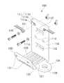
도 1은 본 발명의 일 실시예에 따른 3D 프린터의 노즐 고정용 브래킷이 구비된 3D 프린터의 사시도이고, 도 2는 본 발명의 일 실시예에 따른 3D 프린터의 노즐 고정용 브래킷에 대한 부분사시도이며, 도 3은 본 발명의 일 실시예에 따른 3D 프린터의 노즐 고정용 브래킷에 대한 부분 분해사시이고, 도 4는 본 발명의 일 실시예에 따른 노즐 고정용 브래킷이 구비된 3D 프린터의 샤프트 고정구에 대한 부분 분해사시도이며, 도 5는 본 발명의 일 실시예에 따른 3D 프린터의 노즐 고정용 브래킷이 구비된 3D 프린터의 샤프트 고정구에 대한 부분 단면도이고, 도 6은 본 발명의 일 실시예에 따른 3D 프린터의 노즐 고정용 브래킷이 구비된 3D 프린터의 스크류 고정구에 대한 부분 사시도이며, 도 7은 본 발명의 일 실시예에 따른 3D 프린터의 노즐 고정용 브래킷이 구비된 3D 프린터의 스크류 고정구에 대한 부분 분해사시도이다.FIG. 1 is a perspective view of a 3D printer provided with a nozzle fixing bracket of a 3D printer according to an embodiment of the present invention, FIG. 2 is a partial perspective view of a nozzle fixing bracket of a 3D printer according to an embodiment of the present invention FIG. 3 is a partial exploded perspective view of a nozzle fixing bracket of a 3D printer according to an embodiment of the present invention. FIG. 4 is a perspective view of a part of the 3D fixing device of the 3D printer with a nozzle fixing bracket according to an embodiment of the present invention. FIG. 5 is a partial cross-sectional view of a shaft fixture of a 3D printer provided with a nozzle fixing bracket of a 3D printer according to an embodiment of the present invention, and FIG. 6 is a partial cross- FIG. 7 is a partial perspective view of a screw fixture of a 3D printer provided with a nozzle fixing bracket of a printer. FIG. 7 is a perspective view of a 3D printer having a nozzle fixing bracket of a printer according to an exemplary embodiment of the present invention. Fig. 3 is a partially exploded perspective view of a screw fastener of a printer. Fig.
본 발명의 바람직한 일 실시 예에 따른 3D 프린터의 노즐 고정용 브래킷은 3D 프린터의 X축 샤프트가 구비된 플레이트 측에 수평이동 가능하게 설치되는 브래킷과, 상기 브래킷 후방의 상단 양측에 형성되되, 상기 브래킷(100)의 가장자리에서 내부를 향해 수평방향으로 절개된 절개홈과, 상기 절개홈의 내측 단부로부터 원형으로 확장 형성되는 절개공과, 상기 절개홈의 상부 및 상기 절개공의 외측에는 상기 브래킷과 연결되어 상기 브래킷이 상기 X축 샤프트 상에서 수평이동 되게 하는 벨트의 돌기가 치합되는 치합홈으로 이루어진 벨트고정부가 포함된다.A nozzle fixing bracket of a 3D printer according to a preferred embodiment of the present invention is a bracket for horizontally movably installed on a plate side provided with an X-axis shaft of a 3D printer, and a bracket provided on both sides of an upper end of the rear of the bracket, A cut-off groove formed in a horizontal direction from an edge of the cut-
이하에는 도 1 내지 도 7을 참조하여 본 발명의 바람직한 일 실시예에 따른 3D 프린터의 노즐 고정용 브래킷(A)의 구성요소들과 그 구성요소들 간의 연결관계에 대해서 상세히 설명하기로 한다.Hereinafter, the components of the nozzle fixing bracket A of the 3D printer according to the preferred embodiment of the present invention and the connection relationship between the components will be described in detail with reference to FIGS. 1 to 7. FIG.
전술한 브래킷(100)은 3D 프린터(1)의 노즐(123)이 작동 가능하게 설치되는 역할을 하는 것으로, 3D 프린터(1)의 X축 샤프트(3)를 따라 수평이동 될 수 있도록 플레이트(170) 측에 설치된다.The
이러한 브래킷(100)은 X축 샤프트(3)가 구비된 플레이트(170) 측에 수평이동 가능하게 설치되되, 상기 X축 샤프트(3) 측에 이동 가능하게 설치되며 수직방향으로 배치되는 제 1 면(110)과, 상기 제 1 면(110)의 하단에서 전방을 향해 수평방향으로 절곡되는 제 2 면(120)과, 상기 제 2 면(120)의 선단에서 상향 경사지게 절곡되는 제 3 면(130)으로 구성된다. 즉, 제 1 면(100)의 하단에서 제 2 면(120)이 수직 절곡되고 제 2 면(120)의 선단에서 제 3 면(130)이 60도 내지 80도로 경사지게 절곡된다. 이때 브래킷(100)은 추후에 설명될 방열슬릿(121)을 통해 그 열기가 원활하게 방열처리 될 수 있는 금속 재질로 제조되는 것이 바람직하다.The
전술한 제 1 면(110)의 상단 양측에는 벨트고정부(111)가 형성되는데, 이 벨트고정부(111)는 브래킷(100)을 이동시키는 벨트(140)가 연결되고, 노즐(123), 센서(126) 및 쿨링 팬(132) 등이 작동 가능하게 설치되는 역할을 한다.A
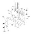
이때 전술한 벨트고정부(111)는 제 1 면(110)의 가장자리에서 내부를 향해 수평방향으로 절개된 절개홈(111a)과, 이 절개홈(111a)의 내측 단부로부터 원형으로 확장 형성되는 절개공(111b)으로 이루어진다. 그리고 절개홈(111a)의 상부와 절개공(111b)의 외측 가장자리에는 브래킷(100)과 연결되어 브래킷(100)을 상기 X축 샤프트(3) 상에서 수평이동 시키기 위한 벨트(140)의 돌기(141)가 치합되는 치합홈(111c)이 형성된다. 이때 벨트(140)의 양단부 측은 그 끝이 동그랗게 권취 된 상태로 절개공(111b) 및 절개홈(111a) 삽입되되 돌기(141) 부분이 상기 치합홈(111c) 내에 고정된다. 그리고 절개공(111b) 측에는 벨트(140)가 이탈되지 않도록 리벳(111d)이 구비된 상태로 볼트 및 너트에 의해 체결 고정된다.The
전술한 플레이트(170)의 일단에는 제 1 구동모터(150)가 작동 가능하게 설치되는데, 이 제 1 구동모터(150)는 그 작동여부에 따라 전술한 브래킷(100)을 X축 샤프트(3)를 따라 수평방향으로 이동시키는 역할을 한다. 이때 플레이트(170)의 타단에는 롤러(160)가 회전 가능하게 설치되는데, 롤러(160)는 제 1 구동모터(150)의 구동축과 수평선상에 위치된다. 그리고 제 1 구동모터(150)의 구동축과 롤러(160) 측에는 벨트(140)가 감겨 져, 제 1 구동모터(150)의 구동 여부에 따라 브래킷(100)이 X축 샤프트(3)를 따라 수평 이동될 수 있다.The
한편, 제 1 면(110) 상에는 X축 샤프트(3)가 그 내부로 관통되는 제 1 부싱(113)이 고정 위치될 수 있도록 제 1 고정홈(112)이 상, 하측에 각각 관통 형성된다. 그리고 상, 하측의 제 1 고정홈(112) 사이에는 X축 샤프트(3) 후방에 배치되어 브래킷(100)과 고정되는 체결부재(115)와 볼트체결 가능하도록 한 쌍의 제 1 체결공(114)이 수평방향으로 관통 형성된다.The
또한, 제 2 면(120)에는 방열슬릿(121) 다수개가 관통 형성되는데, 이 방열슬릿(121)은 노즐(123)의 열기를 공기중으로 방열시키는 역할을 하는 것으로, 이 방열슬릿(121)은 제 1 면(110)과 제 3 면(130) 일부까지 연장 형성된다.A plurality of
그리고 방열슬릿(121)이 형성된 제 2 면(120)의 중앙측에는 노즐 장착구(122)가 관통 형성되고, 제 2 면(120)의 측면에는 센서 고정구(125)가 관통 형성된 돌출부(124)가 형성되며, 제 3 면(130)의 단부에는 쿨링 팬(132)이 설치될 수 있도록 한 쌍의 쿨링 팬 장착구(131)가 수평방향으로 관통 형성된다.A
따라서 3D 프린터의 노즐 고정용 브래킷(A)에 의해 3D 프린터(1)의 노즐(123)과, 이 노즐(123)이 샤프트를 따라 이동되게 하는 벨트(140)가 하나의 브래킷(100)에 설치되게 함으로써 그 구성이 심플하고 제작기간 및 비용이 절감될 수 있다.The
한편, 전술한 X축 샤프트(3)는 3D 프린터의 샤프트 고정구(B)에 의해서 3D 프린터(1) 측에 용이하게 설치될 수 있다. 이때 본 발명의 바람직한 일 실시예에서는 X축 샤프트(3)에 한해서 설명하였지만, Y축 샤프트(5) 및 Z축 샤프트(7) 또한 동일한 방법으로 체결 가능함은 물론이다.On the other hand, the
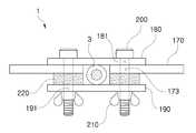
전술한 플레이트(170) 내부에는 X축 샤프트(3)가 수평방향으로 위치될 수 있도록 이에 대응되는 형상의 중공부(171)가 형성되고, 중공부(171)의 양측 가장자리에는 X축 샤프트(3)의 단부가 삽입될 수 있도록 설치홈(172)이 서로 대향되는 위치에 내향 오목하게 형성되며, 설치홈(172)의 양측에 제 2 체결공(173)이 관통 형성되고, 설치홈(172) 내에 삽입된 X축 샤프트(3)의 전면에는 제 1 지지편(180)이 위치되어 X축 샤프트(3)의 일측이 지지되게 하며, 제 1 지지편(180) 양측에는 제 2 체결공(173)과 연통되는 제 3 체결공(181)이 관통 형성되고, 설치홈(172) 내에 삽입된 샤프트의 후면에는 제 2 지지편(190)이 위치되어 X축 샤프트(3)의 타측이 지지되게 하며, 제 2 지지편(190) 양측에는 제 2 체결공(173) 및 제 3 체결공(181)과 연통되는 제 4 체결공(191)이 관통 형성되고, 제 2 체결공(173), 제 3 체결공(181) 및 제 4 체결공(191) 내에는 제 1 체결볼트(200)가 일체로 관통되며, 제 1 체결볼트(200)의 단부에는 제 1 체결너트(210)가 나사결합되어 제 1 지지편(180) 및 제 2 지지편(190)을 플레이트(170) 측에 위치 고정되게 한다.The
전술한 플레이트(170)는 X축 샤프트(3)가 설치되게 하는 역할을 하는데, 이러한 플레이트(170)는 그 내부에 길이방향으로 중공부(171)가 형성되고 중공부(171)의 양측으로는 설치홈(172)이 서로 대향되게 형성되며 이 설치홈(172)의 상, 하측에는 각각 제 2 체결공(173)이 형성된다.The
이때 X축 샤프트(3)와 Z축 샤프트(7)는 중공부(171) 내에 위치되고 이 중공부(171) 양측에 형성된 설치홈(172) 내에 각각의 샤프트 양단이 삽입되지만, 도 1에 도시되는 바와 같이 Y축 샤프트(5)는 중공부(171) 형성됨 없이 그 양측에 형성된 설치홈(172) 내에 Y축 샤프트(5)의 양단이 삽입된다.At this time, the
그리고 전술한 양측의 설치홈(172) 내에는 X축 샤프트(3) 양단이 각각 삽입 고정되는데, 이 고정홈은 X축 샤프트(3)가 별도의 체결구성 없이 플레이트(170) 측에 고정 설치될 수 있게 해주는 역할을 한다. 이때 X축 샤프트(3)는 상, 하측에 수평방향으로 두 개가 구비된다. 서로 대향되게 설치된 양측의 설치홈(172)은 상기 X축 샤프트(3)의 양단이 그 내부에 각각 밀착 위치될 수 있도록 X축 샤프트(3)의 길이에 대응되게 형성되는 것으로 한다.Both ends of the
또한, 전술한 플레이트(170)의 양측에는 제 2 고정홈(174)이 형성되는데, 이 제 2 고정홈(174)은 제 2 부싱(175)이 위치 고정되게 하는 역할을 하며, 제 2 부싱(175) 내에는 플레이트(170)의 수직방향 이동이 안내되는 Z축 샤프트(7)가 삽입 위치된다.A
한편, 전술한 설치홈(172) 내에 삽입된 X축 샤프트(3)의 전면에는 제 1 지지편(180)이 위치되는데, 이 제 1 지지편(180)은 X축 샤프트(3)의 일측을 지지해 주는 역할을 하는 것으로 그 양측에는 제 2 체결공(173)과 연통되는 제 3 체결공(181)이 관통 형성된다.The
또한, 전술한 설치홈(172) 내에 삽입된 X축 샤프트(3)의 후면에는 제 2 지지편(190)이 위치되는데, 이 제 2 지지편(190)은 X축 샤프트(3)의 타측을 지지해 주는 역할을 하는 것으로 그 양측에는 제 2 체결공(173) 및 제 3 체결공(181)과 연통되는 제 4 체결공(191)이 관통 형성된다. 이러한 제 2 지지편(190)은 전술한 제 1 지지편(180)과 동일한 형상으로 형성되며, 제 1 지지편(180)과 제 2 지지편(190) 모두 샤프트의 설치 개수에 따라 그 길이와 체결공의 형성 개수가 변경될 수 있다.The second supporting
그리고 제 2 체결공(173), 제 3 체결공(181) 및 제 4 체결공(191) 내에 제 1 체결볼트(200)가 일체로 관통되고, 제 1 체결볼트(200)의 단부에 제 1 체결너트(210)가 나사결합되어 제 1 지지편(180) 및 제 2 지지편(190)을 상기 플레이트(170) 측에 위치고정시킨다. 따라서 설치홈(172) 내에 그 양단이 삽입된 X축 샤프트(3)의 전, 후면에 각각 제 1 지지편(180)과 제 2 지지편(190)이 위치되어 X축 샤프트(3)가 설치홈(172) 내에서 이탈되지 않고 위치고정될 수 있다. 이때 전술한 제 2 지지편(190)의 일측에는 추후에 설명될 고정너트(250)의 측면이 삽입 고정되는 너트고정홈(192)이 형성된다.The
설치홈(172)의 두께와 X축 샤프트(3)의 두께는 동일하게 형성되지만, X축 샤프트(3)의 두께가 더 두꺼울 경우 플레이트(170)와 제 1 지지편(180) 사이와 플레이트(170)와 제 2 지지편(190) 사이에 스페이서(220)가 선택적으로 구비될 수 있다.The thickness of the mounting
따라서 3D 프린터의 샤프트 고정구(B)에 의해 3D 프린터(1)에서 노즐(123)을 X축, Y축 및 Z축 방향으로 이동시키기 위한 샤프트를 별도의 체결구성 없이 3D 프린터(1) 측에 직결되게 함으로써 제작시간 및 비용이 절감될 수 있게 된다.Therefore, the shaft for moving the
한편, 전술한 플레이트(170)를 수직이동 시키기 위한 스크류(240)와 플레이트(170)의 수직이동이 안내되는 Z축 샤프트(7)는 3D 프린터의 스크류 고정구(C)에 의해 일체로 고정 설치되되 서로 독립적으로 작동 될 수 있다.The
전술한 3D 프린터의 스크류 고정구(C)에는, 양측에 한 쌍의 제 5 체결공(176)이 형성되고 제 5 체결공(176) 사이에 제 2 고정홈(174)이 형성되며 일면에 3D 프린터(1)의 X축 샤프트(3)를 고정시키되 그 일측에 너트고정홈(192)이 형성된 제 2 지지편(190)이 구비되는 플레이트(170)와, 제 2 고정홈(174) 내에 위치되는 제 2 부싱(175)과, 제 2 부싱(175) 내에 관통 위치되며 플레이트(170)의 수직방향 이동이 안내되는 Z축 샤프트(7)와, 3D 프린터(1)의 양 측면에 작동 가능하게 설치되는 제 2 구동모터(230)와, 제 2 구동모터(230)의 구동축 상에 연결되어 제 2 구동모터(230)의 작동 여부에 따라 회전되되 그 외주연에 나사산이 형성되며 Z축 샤프트(7)와 평행되게 배치되는 스크류(240)와, 육각너트 형상으로 형성되어 스크류(240)가 그 내부로 나사결합 되되 제 2 구동모터(230)의 작동 여부에 따라 스크류(240)를 타고 수직방향 이동되고 그 측면이 상기 너트고정홈(192) 내에 삽입되며 그 일면은 플레이트(170) 측에 지지되어 스크류(240) 회전시 그 유동이 방지되는 고정너트(250)와, 고정너트(250)의 타면과 제 2 부싱(175)과 동시에 면접되게 배치되고 그 양측에는 제 5 체결공(176)에 대응되는 제 6 체결공(261)이 형성되는 제 3 지지편(260)과, 제 5 체결공(176) 및 제 6 체결공(261) 내에 일체로 관통되는 제 2 체결볼트(270)와, 제 2 체결볼트(270)의 단부에 나사결합 되어 제 3 지지편(260)이 위치고정 되게 하여 제 3 지지편(260)에 의해 제 2 부싱(175) 및 상기 고정너트(250)이 타면이 지지됨에 따라 제 2 구동모터(230)의 작동시 플레이트(170)가 Z축 샤프트(7)를 따라 수직이동 되게 하는 제 2 체결너트(280)가 포함된다.The screw fastener C of the 3D printer described above is provided with a pair of fifth fastening holes 176 on both sides thereof and a
전술한 플레이트(170) 양측에는 한 쌍의 제 5 체결공(176)이 형성되고, 이 제 5 체결공(176) 사이에 제 2 고정홈(174)이 형성되며, 일면에 3D 프린터(1)의 X축 샤프트(3)를 고정시키되 그 일측에 너트고정홈(192)이 형성된 제 2 지지편(190)이 구비된다. 이때 제 2 지지편(190)은 전술한 X축 샤프트(3)의 후면이 고정되게 하는 것이다.A pair of fifth fastening holes 176 are formed on both sides of the
전술한 제 2 고정홈(174) 내에는 제 2 부싱(175)이 위치되는데, 이 제 2 부싱(175)은 Z축 샤프트(7)가 그 내부로 삽입됨으로써 플레이트(170)의 수직방향 이동이 안내되게 하는 역할을 하게 된다. 그리고 제 2 부싱(175) 내에는 Z축 샤프트(7)가 관통 위치된다.A
한편, 3D 프린터(1)의 양 측면에는 제 2 구동모터(230)가 작동 가능하게 설치되는데, 이 제 2 구동모터(230)는 플레이트(170)가 수직방향 이동되게 하는 동력을 전달하는 역할을 한다.A
그리고 전술한 제 2 구동모터(230)의 구동축 상에는 스크류(240)가 연결되는데, 전술한 스크류(240)는 제 2 구동모터(230)의 작동 여부에 따라 양방향 회전됨으로써 추후에 설명될 고정너트(250)가 수직이동 되게 하는 역할을 한다. 이러한 스크류(240)는 그 외주연에 나사산이 형성되며 Z축 샤프트(7)와 평행되게 배치된다.A
전술한 스크류(240)는 고정너트(250) 내로 나사결합 되는데, 이 고정너트(250)는 제 2 구동모터(230)의 작동 여부에 따라 스크류(240)를 타고 수직방향 이동되는 역할을 하는 것으로, 그 측면이 너트고정홈(192) 내에 삽입되며 그 일면은 플레이트(170) 측에 지지되어 스크류(240) 회전시 그 유동이 방지된다. 이러한 고정너트(250)는 육각너트 형상으로 형성되어 플레이트(170)와 추후에 설명될 제 3 지지편(260)에 의해 그 양측이 지지 될 경우 그 방향이 고정될 수 있어 스크류(240) 회전시 헛도는 현상이 방지될 수 있다.The
한편, 전술한 고정너트(250)의 타면과 제 2 부싱(175)에는 제 3 지지편(260)이 면접되게 배치되는데, 이 제 3 지지편(260)은 고정너트(250)와 제 2 부싱(175)이 동시에 위치 고정되게 지지해주는 역할을 한다. 이와 같은 제 3 지지편(260) 양측에는 전술한 제 5 체결공(176)에 대응되는 제 6 체결공(261)이 형성된다.The
그리고 전술한 제 5 체결공(176) 및 제 6 체결공(261) 내에는 제 2 체결볼트(270)가 일체로 관통되고, 제 2 체결볼트(270)의 단부에는 제 2 체결너트(280)가 나사결합 된다. 전술한 제 2 체결볼트(270) 및 제 2 체결너트(280)의 체결에 의해 제 3 지지편(260)이 위치고정 되고, 제 3 지지편(260)에 의해 제 2 부싱(175) 및 고정너트(250)이 타면이 지지 됨에 따라 제 2 구동모터(230)의 작동시 플레이트(170)가 Z축 샤프트(7)를 따라 수직이동 될 수 있다.The
따라서 3D 프린터의 스크류 고정구(C)에 의해 3D 프린터(1)의 스크류(240)와 Z축 샤프트(7)가 각각의 체결구성에 의해 설치되지 않고 일체로 설치되되 각각 독립적으로 작동될 수 있어 제작시간 및 비용이 절감될 수 있다. 또한, 스크류(240)의 회전 방향에 따라 스크류(240)를 따라 이동되는 고정너트(250)의 양면이 각각 플레이트(170)와 제 2 지지편(190)에 의해 고정되고 동시에 그 측면이 너트고정홈(192)에 의해 지지 됨에 따라 스크류(240) 회전시 고정너트(250)의 유동 되거나 헛도는 오작동이 방지되어 노즐(123)이 정확한 위치로 오차 없이 이동될 수 있다.Therefore, the
위에서 몇몇 실시 예가 예시적으로 설명 되었음에도 불구하고, 본 발명이 이의 취지 및 범주에서 벗어남 없이 다른 여러 형태로 구체화될 수 있다는 사실은 해당 기술에 통상의 지식을 가진 이들에게는 자명한 것이다. 따라서 상술 된 실시 예는 제한적인 것이 아닌 예시적인 것으로 여겨져야 하며, 첨부된 청구항 및 이의 동등 범위 내의 모든 실시에는 본 발명의 범주 내에 포함된다고 할 것이다.It is to be understood by those skilled in the art that the present invention may be embodied in many other forms without departing from the spirit or scope of the present invention, It is therefore intended that the above-described embodiments be considered as illustrative rather than restrictive, and that all implementations within the scope of the appended claims and their equivalents are intended to be included within the scope of the present invention.
A : 3D 프린터의 노즐 고정용 브래킷
B : 3D 프린터의 샤프트 고정구
C : 3D 프린터의 스크류 고정구
1 : 3D 프린터
3 : X축 샤프트
5 : Y축 샤프트
7 : Z축 샤프트
100 : 브래킷
110 : 제 1 면
111 : 벨트고정부
111a : 절개홈
111b : 절개공
111c : 치합홈
111d : 리벳
112 : 제 1 고정홈
113 : 제 1 부싱
114 : 제 1 체결공
115 : 체결부재
120 : 제 2 면
121 : 방열슬릿
122 : 노즐 장착구
123 : 노즐
124 : 돌출부
125 : 센서 고정구
126 : 센서
130 : 제 3 면
131 : 쿨링 팬 장착구
132 : 쿨링 팬
140 : 벨트
141 : 돌기
150 : 제 1 구동모터
160 : 롤러
170 : 플레이트
171 : 중공부
172 : 설치홈
173 : 제 2 체결공
174 : 제 2 고정홈
175 : 제 2 부싱
176 : 제 5 체결공
180 : 제 1 지지편
181 : 제 3 체결공
190 : 제 2 지지편
191 : 제 4 체결공
192 : 너트고정홈
200 : 제 1 체결볼트
210 : 제 1 체결너트
220 : 스페이서
230 : 제 2 구동모터
240 : 스크류
250 : 고정너트
260 : 제 3 지지편
261 : 제 6 체결공
270 : 제 2 체결볼트
280 : 제 2 체결너트A: Nozzle fixing bracket for 3D printer
B: 3D printer's shaft fixture
C: screw fixture of 3D printer
1: 3D printer
3: X-axis shaft
5: Y shaft
7: Z shaft
100: Bracket
110: first side
111: Belt fixing portion
111a: incision groove
111b: incision ball
111c:
111d: Rivet
112: first fixing groove
113: first bushing
114: first fastening hole
115: fastening member
120: second side
121: Heat dissipating slit
122: nozzle mounting hole
123: Nozzles
124:
125: Sensor fixture
126: Sensor
130: Third side
131: Cooling fan mounting hole
132: Cooling fan
140: Belt
141:
150: first drive motor
160: Roller
170: Plate
171:
172: Installation home
173: second fastening hole
174: second fixing groove
175: Second bushing
176: Fifth fastening hole
180: first supporting piece
181: Third fastening hole
190: second supporting piece
191: Fourth fastener
192: Nut fixing groove
200: first fastening bolt
210: first fastening nut
220: Spacer
230: second drive motor
240: Screw
250: Fixing nut
260: third supporting piece
261: Sixth fastener
270: second fastening bolt
280: second fastening nut
Claims (12)
Translated fromKorean상기 브래킷(100) 후방의 상단 양측에 형성되되, 상기 브래킷(100)의 가장자리에서 내부를 향해 수평방향으로 절개된 절개홈(111a)과, 상기 절개홈(111a)의 내측 단부로부터 원형으로 확장 형성되는 절개공(111b)과, 상기 절개홈(111a)의 상부 및 상기 절개공(111b)의 외측에는 상기 브래킷(100)과 연결되어 상기 브래킷(100)이 상기 X축 샤프트(3) 상에서 수평이동 되게 하는 벨트(140)의 돌기(141)가 치합되는 치합홈(111c)으로 이루어진 벨트고정부(111);를 포함하고,
상기 브래킷(100)은 수직방향으로 배치되어 상기 플레이트(170) 측에 고정되며 상기 벨트고정부(111)가 형성된 제 1 면(110)과, 상기 제 1 면(110)의 하단에서 전방을 향해 수평방향으로 절곡되는 제 2 면(120)과, 상기 제 2 면(120)의 선단에서 상향 경사지게 절곡되는 제 3 면(130)으로 구성되며,
상기 제 1 면(110) 상에는 상기 X축 샤프트(3)가 그 내부로 관통되는 제 1 부싱(113)이 고정 위치될 수 있도록 제 1 고정홈(112)이 상, 하측에 각각 관통 형성되고,
상기 제 2 면(120)에는 방열슬릿(121) 다수개가 관통 형성되되, 상기 방열슬릿(121)은 상기 제 1 면(110)과 제 3 면(130) 일부까지 연장 형성되며,
상기 제 3 면(130)의 단부에는 한 쌍의 쿨링 팬 장착구(131)가 수평방향으로 관통 형성되며,
상기 플레이트(170) 내부에는 상기 X축 샤프트(3)가 위치될 수 있도록 중공부(171)가 형성되고, 상기 중공부(171)의 양측 가장자리에는 상기 X축 샤프트(3)의 단부가 삽입될 수 있도록 설치홈(172)이 서로 대향되는 위치에 내향 오목하게 형성되며, 상기 설치홈(172)의 양측에 제 2 체결공(173)이 관통 형성되고, 상기 설치홈(172) 내에 삽입된 상기 X축 샤프트(3)의 전면에는 제 1 지지편(180)이 위치되어 상기 X축 샤프트(3)의 일측이 지지되게 하며, 상기 제 1 지지편(180) 양측에는 상기 제 2 체결공(173)과 연통되는 제 3 체결공(181)이 관통 형성되고, 상기 설치홈(172) 내에 삽입된 상기 샤프트의 후면에는 제 2 지지편(190)이 위치되어 상기 X축 샤프트(3)의 타측이 지지되게 하며, 상기 제 2 지지편(190) 양측에는 상기 제 2 체결공(173) 및 제 3 체결공(181)과 연통되는 제 4 체결공(191)이 관통 형성되고, 상기 제 2 체결공(173), 제 3 체결공(181) 및 제 4 체결공(191) 내에는 제 1 체결볼트(200)가 일체로 관통되며, 상기 제 1 체결볼트(200)의 단부에는 제 1 체결너트(210)가 나사결합 되어 상기 제 1 지지편(180) 및 제 2 지지편(190)을 상기 플레이트 측에 위치 고정되게 하는 것을 특징으로 하는 3D 프린터의 노즐 고정용 브래킷.
A bracket 100 installed horizontally on the side of the plate 170 provided with the X-axis shaft 3 of the 3D printer 1; And
A cutout groove 111a formed on both sides of the upper end of the bracket 100 and horizontally extending from an edge of the bracket 100 toward the inside thereof and a cutout groove 111a formed in a circular shape extending from an inner end of the cutout cutout 111a And the bracket 100 is connected to the outer side of the cutout hole 111b and the cutout hole 111b so that the bracket 100 is moved horizontally on the X- And a belt fixing portion 111 made up of a pair of engagement grooves 111c to which the projections 141 of the belt 140 to be engaged are engaged,
The bracket 100 includes a first surface 110 formed in a vertical direction and fixed to the plate 170 side and having the belt fixing portion 111 formed thereon, A second surface 120 bent in a horizontal direction and a third surface 130 bent upwardly from the tip of the second surface 120,
A first fixing groove 112 is formed on the first surface 110 so that the first bushing 113 through which the X-axis shaft 3 passes can be fixedly positioned,
A plurality of heat dissipating slits 121 are formed in the second surface 120 and the heat dissipating slits 121 extend to a portion of the first surface 110 and the third surface 130,
At the end of the third surface 130, a pair of cooling fan mounting holes 131 are formed in the horizontal direction,
A hollow portion 171 is formed in the plate 170 so that the X-axis shaft 3 can be positioned and the ends of the X-axis shaft 3 are inserted into both sides of the hollow portion 171 A second fastening hole 173 is formed on both sides of the mounting recess 172 so that the second fastening hole 173 is formed in the mounting recess 172, The first supporting piece 180 is positioned on the front surface of the X axis shaft 3 so that one side of the X axis shaft 3 is supported and the second fixing holes 173 And a second support piece 190 is disposed on a rear surface of the shaft inserted into the installation groove 172 so that the other side of the X-axis shaft 3 And a fourth fastening hole 191 communicating with the second fastening hole 173 and the third fastening hole 181 is formed on both sides of the second support piece 190, And the first fastening bolt 200 is integrally passed through the second fastening hole 173, the third fastening hole 181 and the fourth fastening hole 191, Wherein a first fastening nut (210) is screwed to an end of the nozzle (200) to fix the first support piece (180) and the second support piece (190) Fixing bracket.
상기 플레이트(170)의 일단에는 제 1 구동모터(150)가 작동 가능하게 설치되고, 상기 플레이트(170)의 타단에는 롤러(160)가 회전 가능하게 설치되는 것을 특징으로 하는 3D 프린터의 노즐 고정용 브래킷.
The method according to claim 1,
Wherein a first driving motor 150 is operatively installed at one end of the plate 170 and a roller 160 is rotatably installed at the other end of the plate 170. [ Bracket.
상기 벨트(140)의 양단부 측은 그 끝이 동그랗게 권취 된 상태로 상기 절개공(111b) 및 절개홈(111a) 삽입되되 상기 돌기(141) 부분이 상기 치합홈(111c) 내에 고정되고, 상기 제 1 구동모터(150)의 구동축과 상기 롤러(160) 측에 감겨 져, 상기 제 1 구동모터(150)의 구동 여부에 따라 상기 브래킷(100)은 X축 샤프트(3)를 따라 수평 이동되는 것을 특징으로 하는 3D 프린터의 노즐 고정용 브래킷.
The method of claim 3,
The both ends of the belt 140 are inserted into the cutout hole 111b and the cutout groove 111a in a state where the end of the belt 140 is wound in a circular shape and the portion of the protrusion 141 is fixed in the catching groove 111c, The bracket 100 is wound around the driving shaft of the driving motor 150 and the roller 160 so that the bracket 100 is horizontally moved along the X-axis shaft 3 depending on whether the first driving motor 150 is driven A nozzle fixing bracket for a 3D printer.
상기 상, 하측의 제 1 고정홈(112) 사이에는 상기 X축 샤프트(3) 후방에 배치되어 상기 브래킷(100)과 고정되는 체결부재(115)와 볼트체결 가능하도록 한 쌍의 제 1 체결공(114)이 수평방향으로 관통 형성되는 것을 특징으로 하는 3D 프린터의 노즐 고정용 브래킷.
The method according to claim 1,
A pair of first fastening holes 112 are provided between the upper and lower first fixing grooves 112 so as to be bolt-fastened to a fastening member 115 which is disposed behind the X-axis shaft 3 and is fixed to the bracket 100. [ (114) is formed in a horizontal direction.
상기 방열슬릿(121)이 형성된 상기 제 2 면(120)의 중앙측에는 노즐 장착구(122)가 관통 형성되는 것을 특징으로 하는 3D 프린터의 노즐 고정용 브래킷.
The method according to claim 1,
Wherein a nozzle mounting hole (122) is formed through the center of the second surface (120) on which the heat dissipating slit (121) is formed.
상기 제 2 면(120)의 측면에는 센서 고정구(125)가 관통 형성된 돌출부(124)가 형성되는 것을 특징으로 하는 3D 프린터의 노즐 고정용 브래킷.
The method according to claim 1,
Wherein a protrusion (124) formed through a sensor fixing hole (125) is formed on a side surface of the second surface (120).
상기 플레이트(170)와 상기 제 1 지지편(180) 사이와 상기 플레이트(170)와 상기 제 2 지지편(190) 사이에는 스페이서(220)가 선택적으로 구비되는 것을 특징으로 하는 3D 프린터의 노즐 고정용 브래킷.The method according to claim 1,
Wherein a spacer 220 is selectively provided between the plate 170 and the first support piece 180 and between the plate 170 and the second support piece 190. [ Bracket for.
Priority Applications (1)
| Application Number | Priority Date | Filing Date | Title |
|---|---|---|---|
| KR1020160114741AKR101798899B1 (en) | 2016-09-07 | 2016-09-07 | Nozzle fixing bracket of 3D-printer |
Applications Claiming Priority (1)
| Application Number | Priority Date | Filing Date | Title |
|---|---|---|---|
| KR1020160114741AKR101798899B1 (en) | 2016-09-07 | 2016-09-07 | Nozzle fixing bracket of 3D-printer |
Publications (1)
| Publication Number | Publication Date |
|---|---|
| KR101798899B1true KR101798899B1 (en) | 2017-11-17 |
Family
ID=60808407
Family Applications (1)
| Application Number | Title | Priority Date | Filing Date |
|---|---|---|---|
| KR1020160114741AActiveKR101798899B1 (en) | 2016-09-07 | 2016-09-07 | Nozzle fixing bracket of 3D-printer |
Country Status (1)
| Country | Link |
|---|---|
| KR (1) | KR101798899B1 (en) |
Citations (2)
| Publication number | Priority date | Publication date | Assignee | Title |
|---|---|---|---|---|
| CN203937195U (en)* | 2014-07-22 | 2014-11-12 | 武汉诣文科技有限公司 | Stable equilibrium's device for 3D printer |
| JP2015128892A (en)* | 2014-01-06 | 2015-07-16 | 三緯國際立體列印科技股▲ふん▼有限公司XYZprinting, Inc. | Print head module |
- 2016
- 2016-09-07KRKR1020160114741Apatent/KR101798899B1/enactiveActive
Patent Citations (2)
| Publication number | Priority date | Publication date | Assignee | Title |
|---|---|---|---|---|
| JP2015128892A (en)* | 2014-01-06 | 2015-07-16 | 三緯國際立體列印科技股▲ふん▼有限公司XYZprinting, Inc. | Print head module |
| CN203937195U (en)* | 2014-07-22 | 2014-11-12 | 武汉诣文科技有限公司 | Stable equilibrium's device for 3D printer |
Similar Documents
| Publication | Publication Date | Title |
|---|---|---|
| US10464261B2 (en) | Dual printhead assembly and 3D printing apparatus using same | |
| KR101528850B1 (en) | 6 DOF(Degrees of Freedom) 3D Printer | |
| WO2016052228A1 (en) | 3d printer ejection head | |
| US9404557B2 (en) | Flexible protective guide internally holding long members | |
| CN104057718B (en) | Print head assembly for three-dimensional printer | |
| US9551436B2 (en) | Protective guide for cables and bracket used for the protective guide | |
| EP3539847A1 (en) | Steering column device | |
| KR101820823B1 (en) | Scrw fixture of 3D-printer | |
| KR101798903B1 (en) | Shaft fixture of 3D-printer | |
| US20180009492A1 (en) | Method for manufacturing shutter device for vehicle | |
| KR101798899B1 (en) | Nozzle fixing bracket of 3D-printer | |
| EP2897260B1 (en) | Motor housing | |
| US10300645B2 (en) | Injection device and axial-center position adjusting method | |
| KR101682602B1 (en) | Apparatus for Parallelism adjustment between two shafts used for linear motion in 3D printer | |
| KR20190072713A (en) | Structure of print-head and slide-rail assemblying method of 3d printer | |
| KR102092882B1 (en) | Stepping mortor | |
| CN220499956U (en) | Guide pulley, guide module and three-dimensional forming equipment | |
| KR101208077B1 (en) | Combination screw bolt of automobile outside mirror and it manufacture method | |
| CN206658370U (en) | Cooling components | |
| JP6220806B2 (en) | Grill shutter assembly method | |
| JP5827884B2 (en) | Glass holder | |
| JP5371212B2 (en) | Spring making machine | |
| JP6236409B2 (en) | Grill shutter | |
| KR20200039048A (en) | 3d printer | |
| JP7346159B2 (en) | Lever rotation mechanism |
Legal Events
| Date | Code | Title | Description |
|---|---|---|---|
| PA0109 | Patent application | Patent event code:PA01091R01D Comment text:Patent Application Patent event date:20160907 | |
| PA0201 | Request for examination | ||
| PE0902 | Notice of grounds for rejection | Comment text:Notification of reason for refusal Patent event date:20170906 Patent event code:PE09021S01D | |
| E701 | Decision to grant or registration of patent right | ||
| PE0701 | Decision of registration | Patent event code:PE07011S01D Comment text:Decision to Grant Registration Patent event date:20171108 | |
| GRNT | Written decision to grant | ||
| PR0701 | Registration of establishment | Comment text:Registration of Establishment Patent event date:20171113 Patent event code:PR07011E01D | |
| PR1002 | Payment of registration fee | Payment date:20171113 End annual number:3 Start annual number:1 | |
| PG1601 | Publication of registration | ||
| PR1001 | Payment of annual fee | Payment date:20201026 Start annual number:4 End annual number:4 | |
| PR1001 | Payment of annual fee | Payment date:20211020 Start annual number:5 End annual number:5 | |
| PR1001 | Payment of annual fee | Payment date:20230102 Start annual number:6 End annual number:6 | |
| PR1001 | Payment of annual fee | Payment date:20231107 Start annual number:7 End annual number:7 | |
| PR1001 | Payment of annual fee | Payment date:20241105 Start annual number:8 End annual number:8 |