KR101795827B1 - Wirelessly powered dielectric barrier discharge lamp, and base station for a wirelessly powered fluid treatment system - Google Patents
Wirelessly powered dielectric barrier discharge lamp, and base station for a wirelessly powered fluid treatment systemDownload PDFInfo
- Publication number
- KR101795827B1 KR101795827B1KR1020127034259AKR20127034259AKR101795827B1KR 101795827 B1KR101795827 B1KR 101795827B1KR 1020127034259 AKR1020127034259 AKR 1020127034259AKR 20127034259 AKR20127034259 AKR 20127034259AKR 101795827 B1KR101795827 B1KR 101795827B1
- Authority
- KR
- South Korea
- Prior art keywords
- lamp
- primary
- lamp assembly
- fluid
- base station
- Prior art date
- Legal status (The legal status is an assumption and is not a legal conclusion. Google has not performed a legal analysis and makes no representation as to the accuracy of the status listed.)
- Expired - Fee Related
Links
Images


Classifications
- H—ELECTRICITY
- H01—ELECTRIC ELEMENTS
- H01J—ELECTRIC DISCHARGE TUBES OR DISCHARGE LAMPS
- H01J65/00—Lamps without any electrode inside the vessel; Lamps with at least one main electrode outside the vessel
- H01J65/04—Lamps in which a gas filling is excited to luminesce by an external electromagnetic field or by external corpuscular radiation, e.g. for indicating plasma display panels
- C—CHEMISTRY; METALLURGY
- C02—TREATMENT OF WATER, WASTE WATER, SEWAGE, OR SLUDGE
- C02F—TREATMENT OF WATER, WASTE WATER, SEWAGE, OR SLUDGE
- C02F1/00—Treatment of water, waste water, or sewage
- C02F1/30—Treatment of water, waste water, or sewage by irradiation
- C02F1/32—Treatment of water, waste water, or sewage by irradiation with ultraviolet light
- C02F1/325—Irradiation devices or lamp constructions
- B—PERFORMING OPERATIONS; TRANSPORTING
- B01—PHYSICAL OR CHEMICAL PROCESSES OR APPARATUS IN GENERAL
- B01D—SEPARATION
- B01D53/00—Separation of gases or vapours; Recovering vapours of volatile solvents from gases; Chemical or biological purification of waste gases, e.g. engine exhaust gases, smoke, fumes, flue gases, aerosols
- B01D53/34—Chemical or biological purification of waste gases
- B01D53/74—General processes for purification of waste gases; Apparatus or devices specially adapted therefor
- C—CHEMISTRY; METALLURGY
- C02—TREATMENT OF WATER, WASTE WATER, SEWAGE, OR SLUDGE
- C02F—TREATMENT OF WATER, WASTE WATER, SEWAGE, OR SLUDGE
- C02F1/00—Treatment of water, waste water, or sewage
- C02F1/28—Treatment of water, waste water, or sewage by sorption
- C02F1/283—Treatment of water, waste water, or sewage by sorption using coal, charred products, or inorganic mixtures containing them
- C—CHEMISTRY; METALLURGY
- C02—TREATMENT OF WATER, WASTE WATER, SEWAGE, OR SLUDGE
- C02F—TREATMENT OF WATER, WASTE WATER, SEWAGE, OR SLUDGE
- C02F1/00—Treatment of water, waste water, or sewage
- C02F1/30—Treatment of water, waste water, or sewage by irradiation
- C02F1/32—Treatment of water, waste water, or sewage by irradiation with ultraviolet light
- H—ELECTRICITY
- H01—ELECTRIC ELEMENTS
- H01F—MAGNETS; INDUCTANCES; TRANSFORMERS; SELECTION OF MATERIALS FOR THEIR MAGNETIC PROPERTIES
- H01F38/00—Adaptations of transformers or inductances for specific applications or functions
- H01F38/14—Inductive couplings
- H—ELECTRICITY
- H01—ELECTRIC ELEMENTS
- H01J—ELECTRIC DISCHARGE TUBES OR DISCHARGE LAMPS
- H01J5/00—Details relating to vessels or to leading-in conductors common to two or more basic types of discharge tubes or lamps
- H01J5/50—Means forming part of the tube or lamps for the purpose of providing electrical connection to it
- H01J5/54—Means forming part of the tube or lamps for the purpose of providing electrical connection to it supported by a separate part, e.g. base
- H01J5/62—Connection of wires protruding from the vessel to connectors carried by the separate part
- H—ELECTRICITY
- H01—ELECTRIC ELEMENTS
- H01J—ELECTRIC DISCHARGE TUBES OR DISCHARGE LAMPS
- H01J65/00—Lamps without any electrode inside the vessel; Lamps with at least one main electrode outside the vessel
- H01J65/04—Lamps in which a gas filling is excited to luminesce by an external electromagnetic field or by external corpuscular radiation, e.g. for indicating plasma display panels
- H01J65/042—Lamps in which a gas filling is excited to luminesce by an external electromagnetic field or by external corpuscular radiation, e.g. for indicating plasma display panels by an external electromagnetic field
- H01J65/046—Lamps in which a gas filling is excited to luminesce by an external electromagnetic field or by external corpuscular radiation, e.g. for indicating plasma display panels by an external electromagnetic field the field being produced by using capacitive means around the vessel
- C—CHEMISTRY; METALLURGY
- C02—TREATMENT OF WATER, WASTE WATER, SEWAGE, OR SLUDGE
- C02F—TREATMENT OF WATER, WASTE WATER, SEWAGE, OR SLUDGE
- C02F2201/00—Apparatus for treatment of water, waste water or sewage
- C02F2201/32—Details relating to UV-irradiation devices
- C02F2201/322—Lamp arrangement
- C02F2201/3222—Units using UV-light emitting diodes [LED]
- C—CHEMISTRY; METALLURGY
- C02—TREATMENT OF WATER, WASTE WATER, SEWAGE, OR SLUDGE
- C02F—TREATMENT OF WATER, WASTE WATER, SEWAGE, OR SLUDGE
- C02F2201/00—Apparatus for treatment of water, waste water or sewage
- C02F2201/32—Details relating to UV-irradiation devices
- C02F2201/322—Lamp arrangement
- C02F2201/3223—Single elongated lamp located on the central axis of a turbular reactor
- C—CHEMISTRY; METALLURGY
- C02—TREATMENT OF WATER, WASTE WATER, SEWAGE, OR SLUDGE
- C02F—TREATMENT OF WATER, WASTE WATER, SEWAGE, OR SLUDGE
- C02F2201/00—Apparatus for treatment of water, waste water or sewage
- C02F2201/32—Details relating to UV-irradiation devices
- C02F2201/326—Lamp control systems
- C—CHEMISTRY; METALLURGY
- C02—TREATMENT OF WATER, WASTE WATER, SEWAGE, OR SLUDGE
- C02F—TREATMENT OF WATER, WASTE WATER, SEWAGE, OR SLUDGE
- C02F2209/00—Controlling or monitoring parameters in water treatment
- C02F2209/005—Processes using a programmable logic controller [PLC]
- C—CHEMISTRY; METALLURGY
- C02—TREATMENT OF WATER, WASTE WATER, SEWAGE, OR SLUDGE
- C02F—TREATMENT OF WATER, WASTE WATER, SEWAGE, OR SLUDGE
- C02F2209/00—Controlling or monitoring parameters in water treatment
- C02F2209/005—Processes using a programmable logic controller [PLC]
- C02F2209/006—Processes using a programmable logic controller [PLC] comprising a software program or a logic diagram
- C—CHEMISTRY; METALLURGY
- C02—TREATMENT OF WATER, WASTE WATER, SEWAGE, OR SLUDGE
- C02F—TREATMENT OF WATER, WASTE WATER, SEWAGE, OR SLUDGE
- C02F2209/00—Controlling or monitoring parameters in water treatment
- C02F2209/005—Processes using a programmable logic controller [PLC]
- C02F2209/008—Processes using a programmable logic controller [PLC] comprising telecommunication features, e.g. modems or antennas
- C—CHEMISTRY; METALLURGY
- C02—TREATMENT OF WATER, WASTE WATER, SEWAGE, OR SLUDGE
- C02F—TREATMENT OF WATER, WASTE WATER, SEWAGE, OR SLUDGE
- C02F2209/00—Controlling or monitoring parameters in water treatment
- C02F2209/02—Temperature
- C—CHEMISTRY; METALLURGY
- C02—TREATMENT OF WATER, WASTE WATER, SEWAGE, OR SLUDGE
- C02F—TREATMENT OF WATER, WASTE WATER, SEWAGE, OR SLUDGE
- C02F2209/00—Controlling or monitoring parameters in water treatment
- C02F2209/06—Controlling or monitoring parameters in water treatment pH
- C—CHEMISTRY; METALLURGY
- C02—TREATMENT OF WATER, WASTE WATER, SEWAGE, OR SLUDGE
- C02F—TREATMENT OF WATER, WASTE WATER, SEWAGE, OR SLUDGE
- C02F2209/00—Controlling or monitoring parameters in water treatment
- C02F2209/11—Turbidity
- C—CHEMISTRY; METALLURGY
- C02—TREATMENT OF WATER, WASTE WATER, SEWAGE, OR SLUDGE
- C02F—TREATMENT OF WATER, WASTE WATER, SEWAGE, OR SLUDGE
- C02F2209/00—Controlling or monitoring parameters in water treatment
- C02F2209/40—Liquid flow rate
- C—CHEMISTRY; METALLURGY
- C02—TREATMENT OF WATER, WASTE WATER, SEWAGE, OR SLUDGE
- C02F—TREATMENT OF WATER, WASTE WATER, SEWAGE, OR SLUDGE
- C02F2303/00—Specific treatment goals
- C02F2303/04—Disinfection
- H—ELECTRICITY
- H01—ELECTRIC ELEMENTS
- H01J—ELECTRIC DISCHARGE TUBES OR DISCHARGE LAMPS
- H01J65/00—Lamps without any electrode inside the vessel; Lamps with at least one main electrode outside the vessel
- H01J65/04—Lamps in which a gas filling is excited to luminesce by an external electromagnetic field or by external corpuscular radiation, e.g. for indicating plasma display panels
- H01J65/042—Lamps in which a gas filling is excited to luminesce by an external electromagnetic field or by external corpuscular radiation, e.g. for indicating plasma display panels by an external electromagnetic field
- H01J65/048—Lamps in which a gas filling is excited to luminesce by an external electromagnetic field or by external corpuscular radiation, e.g. for indicating plasma display panels by an external electromagnetic field the field being produced by using an excitation coil
Landscapes
- Engineering & Computer Science (AREA)
- Physics & Mathematics (AREA)
- Plasma & Fusion (AREA)
- Environmental & Geological Engineering (AREA)
- Chemical & Material Sciences (AREA)
- Electromagnetism (AREA)
- Life Sciences & Earth Sciences (AREA)
- Hydrology & Water Resources (AREA)
- Water Supply & Treatment (AREA)
- Organic Chemistry (AREA)
- Power Engineering (AREA)
- Health & Medical Sciences (AREA)
- Toxicology (AREA)
- Biomedical Technology (AREA)
- Analytical Chemistry (AREA)
- General Chemical & Material Sciences (AREA)
- Oil, Petroleum & Natural Gas (AREA)
- Chemical Kinetics & Catalysis (AREA)
- Physical Water Treatments (AREA)
- Physical Or Chemical Processes And Apparatus (AREA)
Abstract
Translated fromKoreanDescription
Translated fromKorean본 발명은 유전체 배리어 방전 램프에 관한 것이다. 특히, 본 발명은 유체 처리 시스템, 발광 시스템 및 다른 응용에 사용하기 위한 유전체 배리어 방전 램프에 관한 것이다.The present invention relates to a dielectric barrier discharge lamp. More particularly, the present invention relates to dielectric barrier discharge lamps for use in fluid treatment systems, light emitting systems, and other applications.
유전체 배리어 방전 램프는 일반적으로 공지되어 있고 특정 파장의 전자기 방사가 요구되는 다양한 응용에 사용된다. 예를 들어, 일부 응용은 폐수 처리 및/또는 음료수의 소독을 포함한다. 이들 응용은 파장이 약 100 nm 내지 280 nm인 자외선 방사를 요구할 수 있다. 다른 응용은 파장이 약 380 nm 내지 750 nm인 것을 요구할 수 있는 일반적인 조명을 위한 가시광의 생성을 포함한다.Dielectric barrier discharge lamps are commonly known and are used in a variety of applications where electromagnetic radiation of a particular wavelength is required. For example, some applications include wastewater treatment and / or disinfection of drinking water. These applications may require ultraviolet radiation with a wavelength of about 100 nm to 280 nm. Other applications include the generation of visible light for general illumination which may require wavelengths of about 380 nm to 750 nm.
유전체 배리어 방전 램프는 통상 임의의 형태일 수 있다. 유전체 배리어 방전 램프의 가장 단순한 형태 중 하나는 외부 튜브 및 그와의 사이에 환형 방전 챔버를 형성하는 동축의 내부 튜브를 포함한다. 내부 튜브 내의 전극과 외부 튜브의 외측 주위의 상대전극은 환형 방전 챔버에 의해 이격된다. 챔버는 통상 가스 방전, 특히 유전체 배리어 방전이 방전 챔버 내에서 개시되자마자 1차 방사를 방출하는 크세논과 같은 희가스 또는 희귀가스를 포함한다. 유전체 배리어 방전 동안, 크세논 분자는 이온과 전자로 해리되어 크세논 플라즈마가 된다. 크세논 플라즈마가 특정 에너지 레벨로 여기되면, 엑시머 분자가 플라즈마 내에 형성된다. 엑시머 분자는 일정 수명 이후에 분리되어, 크세논 플라즈마의 경우 피크 파장이 약 172 nm인 광자를 방출한다. 이러한 에너지는 외부 튜브의 내측 상에 침착된 발광 층을 통하여 175 nm 내지 280 nm 범위로 변환될 수 있다. 적어도 외부 튜브는 석영과 같은 반투명 물질로 형성될 수 있어서, 물 또는 공기의 소독을 위해, 또는 다른 응용을 위해 자외선 방사를 방출한다.The dielectric barrier discharge lamps may typically be of any shape. One of the simplest forms of dielectric barrier discharge lamps includes an outer tube and a coaxial inner tube forming an annular discharge chamber therebetween. The electrode in the inner tube and the counter electrode around the outer periphery of the outer tube are spaced apart by the annular discharge chamber. The chamber typically contains a rare gas or rare gas, such as xenon, which emits primary radiation as soon as the dielectric barrier discharge is initiated in the discharge chamber. During the dielectric barrier discharge, the xenon molecules are dissociated into ions and electrons and become xenon plasma. When the xenon plasma is excited to a certain energy level, excimer molecules are formed in the plasma. The excimer molecules are separated after a certain lifetime and emit photons with a peak wavelength of about 172 nm for xenon plasma. This energy can be converted to a range of 175 nm to 280 nm through the emissive layer deposited on the inside of the outer tube. At least the outer tube may be formed of a translucent material, such as quartz, to emit ultraviolet radiation for disinfection of water or air, or for other applications.
종래 시스템은 공통 자기 코어 둘레에 권취되어 주 전압 또는 제1 전압을 전극과 상대전극을 가로질러 인가하기 위한 제2 전압으로 변환시키는 승압 변압기를 또한 포함할 수 있다. 그러나, 승압 변압기는 통상 전원 장치 및 램프 몸체에 물리적인 연결을 포함하여야 한다. 사용 중에, 변압기와 램프 몸체 사이의 연결(예를 들어, 전기적 접촉)은 유체 및 부식에 취약할 수 있다. 더욱이, 종래의 유전체 배리어 가스 방전 램프에 의한 유체의 효율적인 처리에 있어서 주요 장애는 적절한 처리를 위해 필요한 레벨보다 높거나 또는 낮은 레벨에서 유체를 조사하는 것이다.Conventional systems may also include a step-up transformer that is wound around a common magnetic core to convert the main voltage or a first voltage to a second voltage for applying across the electrode and counter electrode. However, the step-up transformer should normally include a physical connection to the power supply and the lamp body. In use, the connection (e.g., electrical contact) between the transformer and the lamp body may be susceptible to fluid and corrosion. Moreover, a major obstacle to the efficient treatment of fluids by conventional dielectric barrier gas discharge lamps is to irradiate the fluid at levels above or below the levels required for proper treatment.
유체 처리 시스템용 유전체 배리어 방전 램프 조립체가 제공된다. 램프 조립체는 유도 세컨더리, 유도 세컨더리에 결합된 제1 전극과 제2 전극, 및 제1 전극과 제2 전극 사이에 개재된 유전체 배리어를 포함하는 램프를 포함할 수 있다. 유전체 배리어는 방전 가스를 포함하는 방전 챔버를 형성할 수 있고, 제1 전극 및 제2 전극들 중 하나는 방전 챔버 내에 연장될 수 있다. 유도 세컨더리는 근처의 유도 프라이머리로부터 전력을 수신하도록 구성되어 방전 챔버 내에서 유전체 배리어 방전을 촉진할 수 있다. 생성된 유전체 배리어 방전은 공기 또는 물의 처리를 위한, 또는 다른 응용을 위한 자외선 광을 생성할 수 있다.A dielectric barrier discharge lamp assembly for a fluid treatment system is provided. The lamp assembly may include a guiding secondary, a first electrode and a second electrode coupled to the induction secondary, and a ramp including a dielectric barrier interposed between the first and second electrodes. The dielectric barrier may form a discharge chamber including a discharge gas, and one of the first electrode and the second electrode may extend into the discharge chamber. The induced secondary may be configured to receive power from a nearby induced primary to facilitate dielectric barrier discharge within the discharge chamber. The resulting dielectric barrier discharge can produce ultraviolet light for treatment of air or water, or for other applications.
일 실시예에서, 램프는 외부 튜브로부터 이격된 내부 튜브를 포함하고 이들 사이에 방전 갭을 형성한다. 제1 전극과 제2 전극 사이에 고전압을 인가함으로써 램프의 외측을 통하여 그리고 주위의 유체로 광을 방출하도록 방전 갭 내에 전기 방전을 일으킬 수 있다. 주위의 유체, 예를 들어 물은 선택적으로 전극의 연장부로서 기능을 할 수 있다. 선택적으로, 램프 조립체는 전극에 결합되고 램프의 외측에 부착된 전도성 메시(mesh)를 포함할 수 있다. 또한 선택적으로, 램프 조립체는 램프로부터 이격된 전기적 유전성 부재(electrically permitable member)를 포함하여 이들 사이에 유체를 수용할 수 있다. 전기적 유전성 부재는, 예를 들어, 유체의 이온화를 방지하기 위하여 제1 전극 및 제2 전극 중 하나 또는 둘 모두로부터 유체를 통상 분리할 수 있다.In one embodiment, the lamp includes an inner tube spaced from the outer tube and forms a discharge gap therebetween. An electric discharge can be generated in the discharge gap to discharge light to the surrounding fluid through the outside of the lamp by applying a high voltage between the first electrode and the second electrode. The surrounding fluid, for example water, can optionally act as an extension of the electrode. Optionally, the lamp assembly may include a conductive mesh coupled to the electrode and attached to the outside of the lamp. Optionally, the lamp assembly also includes an electrically permitable member spaced from the lamp to receive fluid therebetween. The electrically dielectric member can typically separate fluid from one or both of the first electrode and the second electrode, for example, to prevent ionization of the fluid.
다른 실시예에서, 베이스 스테이션이 제공된다. 램프 조립체는 베이스 스테이션 내에 제거 가능하게 수용될 수 있고, 베이스 스테이션은 유도 프라이머리를 포함하여 무선 전력 공급원을 램프 조립체에 제공할 수 있다. 베이스 스테이션은 제어기, 램프 펄스 구동기, 램프 센서, 및 수류 센서(water flow sensor)를 갖는 주 회로를 더 포함할 수 있다. 제어기는 램프 펄스 구동기에 전기적으로 결합되어 일련의 짧은 지속 시간 펄스로 유도 프라이머리를 구동할 수 있다. 제어기는 램프 센서 및 수류량 센서로부터의 피드백을 감시하여 램프 펄스 구동기의 성능을 제어할 수 있다.In another embodiment, a base station is provided. The lamp assembly may be removably received within the base station and the base station may include a guided primary to provide a wireless power source to the lamp assembly. The base station may further include a main circuit having a controller, a lamp pulse driver, a lamp sensor, and a water flow sensor. The controller may be electrically coupled to the ramp pulse driver to drive the induced primary with a series of short duration pulses. The controller can monitor the feedback from the lamp sensor and the flow sensor to control the performance of the ramp pulse driver.
또 다른 실시예에서, 유도 세컨더리 및 램프는 동축일 수 있고, 유도 세컨더리는 램프의 적어도 일부 둘레에 연장될 수 있다. 유도 프라이머리 및 유도 세컨더리는 서로 동심 관계로 배열될 수 있고, 유도 세컨더리는 자기 코어를 포함하고 유도 프라이머리에 의해 형성되는 내경보다 작은 외경을 형성한다. 대안적으로, 유도 세컨더리는 유도 프라이머리에 의해 형성되는 외경보다 큰 내경을 형성하고, 프라이머리가 자기 코어를 포함한다. 램프 조립체는 유도 세컨더리를 적어도 부분적으로 봉지하고 베이스 스테이션과 적어도 부분적으로 상호 끼워 맞춤되는 세컨더리 하우징을 포함할 수 있다.In another embodiment, the induced secondary and ramp may be coaxial, and the induced secondary may extend around at least a portion of the ramp. The guided primary and guided secondary can be arranged concentrically with respect to each other, and the guided secondary includes the magnetic core and forms an outer diameter smaller than the inner diameter formed by the guided primary. Alternatively, the guided secondary forms an inner diameter larger than the outer diameter formed by the guiding primary, and the primary includes the magnetic core. The lamp assembly may include a secondary housing at least partially encapsulating the guided secondary and at least partially interfitting with the base station.
또 다른 실시예에서, 베이스 스테이션은 유체 품질 센서를 포함할 수 있다. 유체 품질 센서는 제어기에 전기적으로 연결된 출력부를 가질 수 있고, 유체 품질 센서는, 예를 들어 유체 탁도, pH, 또는 온도를 포함하는, 처리되는 유체의 특성을 판단하도록 구성될 수 있다. 유체 품질 센서의 출력에 기초하여, 제어기는 램프 조립체로부터 방출된 자외선 광의 강도를 제어하거나 가변시킬 수 있다. 선택적으로, 램프는 방사된 광을 자외선 파장 광으로 변환시키는 발광 층을 포함할 수 있거나, 또는 램프는 발광 층의 도움 없이 자외선 방사를 방출하도록 가스를 포함할 수 있다.In yet another embodiment, the base station may include a fluid quality sensor. The fluid quality sensor may have an output electrically coupled to the controller and the fluid quality sensor may be configured to determine the characteristics of the fluid being treated, including, for example, fluid turbidity, pH, or temperature. Based on the output of the fluid quality sensor, the controller can control or vary the intensity of the ultraviolet light emitted from the lamp assembly. Optionally, the lamp may include a light emitting layer that converts the emitted light into ultraviolet light, or the lamp may include gas to emit ultraviolet radiation without the aid of a light emitting layer.
또 다른 실시예에서, 램프 조립체는 무선 전력 공급식 가스 방전 램프, 무선 전력 공급식 백열 램프, 또는 다른 무선 전력 공급식 장치를 위한 기존의 베이스 스테이션에 의해 구동되도록 구성될 수 있다. 본 실시예에서, 램프 조립체는 유도 세컨더리와 제1 및 제2 전극 사이에 전기적으로 연결된 램프 펄스 구동기를 포함할 수 있다. 램프 펄스 구동기는 유도 세컨더리 내에 유도된 제1 시변 전압을 제1 전극 및 제2 전극을 가로질러 인가되는 제2 시변 전압으로 변환시키도록 구성되어 방전 챔버 내에 유전체 배리어 방전을 유도할 수 있다.In yet another embodiment, the lamp assembly may be configured to be driven by a conventional base station for a wireless power-fed gas discharge lamp, a wireless power-fed incandescent lamp, or other wireless power-fed device. In this embodiment, the lamp assembly may include a ramp pulse driver electrically coupled between the induction secondary and the first and second electrodes. The ramp pulse driver may be configured to convert the first time-varying voltage induced in the inductive secondary to a second time-varying voltage applied across the first and second electrodes to induce a dielectric barrier discharge in the discharge chamber.
또 다른 실시예에서, 램프 조립체는 베이스 스테이션 및 선택적으로 유도 프라이머리와 무선 통신을 위한 RF 안테나 및 메모리 태그를 포함할 수 있다. 예를 들어, 유도 프라이머리는 처리되는 물의 수질, 유전체 배리어 방전 램프의 조명 개수, 및 조명 시간과 같은 데이터를 메모리 태그로부터 판독하고 그에 기입하도록 통신 모드에서 작동할 수 있다. 더욱이, 유도 프라이머리는 태그로부터의 누적된 이전 작동 데이터 및 고유의 램프 일련 번호와 같은 데이터를 메모리 태그로부터 판독하도록 작동할 수 있다. 누적된 작동 데이터를 주어진 램프 조립체에 대한 권장 한계와 비교함으로써, 베이스 스테이션은 사용자 및/또는 서비스 직원에게, 무엇보다도, 사용 정보 또는 램프 조립체나 다른 구성요소의 교체에 대한 정확한 시간의 표시를 제공할 수 있다. 작동 시에, 시스템은 각각의 사용 전에 메모리 태그로부터 데이터를 판독하도록 구성될 수 있고 각각의 사용 후에 메모리 태그에 데이터를 기입하도록 구성될 수 있다. RF 판독기/기입기 코일로서 1차 코일을 사용하여 RF 통신용 개별 코일에 대한 필요성을 또한 없앨 수 있다.In yet another embodiment, the lamp assembly may include a base station and, optionally, an RF antenna and a memory tag for wireless communication with the induced primary. For example, the induced primary may operate in a communication mode to read and write data from the memory tag, such as the water quality of the water being treated, the number of illumination of the dielectric barrier discharge lamp, and the illumination time. Moreover, the induced primary can operate to read data from the memory tag, such as accumulated previous operating data from the tag and a unique lamp serial number. By comparing the cumulative operating data with the recommended limits for a given lamp assembly, the base station can provide the user and / or service personnel with, among other things, an indication of the exact time of use information or replacement of the lamp assembly or other component . In operation, the system may be configured to read data from the memory tag prior to each use and may be configured to write data to the memory tag after each use. The use of primary coils as RF reader / writer coils also eliminates the need for individual coils for RF communications.
본 발명의 이들 및 다른 특징과 이점은 첨부된 도면 및 후속하는 특허청구범위에 따라 고려할 때 본 발명의 이하 설명으로부터 명백해질 것이다.These and other features and advantages of the present invention will become apparent from the following description of the invention when considered in accordance with the accompanying drawings and the following claims.
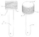
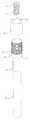
도 1은 유전체 배리어 방전 램프 조립체의 정면도 및 사시도이다.
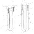
도 2는 도 1의 램프 조립체의 수직 단면도이다.
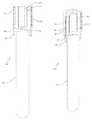
도 3은 도 1의 램프 조립체의 부분 분해도이다.
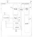
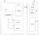
도 4는 베이스 스테이션 및 램프 조립체의 블록도이다.
도 5는 시간에 따른 램프 전압을 나타내는 그래프이다.
도 6은 시간에 따른 구동 전압을 나타내는 그래프이다.
도 7은 도 6의 구동 전압에 응답하는 램프 전압을 나타내는 그래프이다.
도 8은 물 처리 시스템의 작동 흐름도이다.
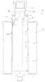
도 9는 전도성 메시 외부 전극을 포함하는 유전체 배리어 방전 램프 조립체의 수직 단면도이다.
도 10은 메시 외부 전극을 따라 유체가 이동하도록 구성된 도 9의 램프 조립체의 수직 단면도이다.
도 11은 베이스 스테이션 수질 센서를 포함하는 램프 조립체 및 베이스 스테이션의 블록도이다.
도 12는 UV 방출 램프 또는 LED를 포함하는 램프 조립체 및 베이스 스테이션의 블록도이다.
도 13은 수질 센서를 포함하는 물 처리 시스템의 작동 흐름도이다.
도 14는 컴퓨터 판독가능 램프 메모리를 포함하는 램프 조립체 및 베이스 스테이션의 블록도이다.
도 15는 컴퓨터 판독가능 램프 메모리 및 수질 센서를 포함하는 물 처리 시스템의 작동 흐름도이다.
도 16은 2차 코일의 코어 내에 수용된 1차 코일을 포함하는 유전체 배리어 방전 램프 조립체의 평면도 및 사시도이다.
도 17은 도 16의 램프 조립체의 수직 단면도이다.
도 18은 도 16의 램프 조립체의 부분 분해 사시도이다.
도 19는 도 16의 램프 조립체의 부분 분해 단면도이다.
도 20은 베이스 스테이션 및 개장된 램프 조립체의 블록도이다.
도 21은 필터 요소를 포함하는 도 20의 램프 조립체의 수직 단면도이다.
도 22는 전기적 유전성 외부 슬리브 및 외부 전극을 포함하는 램프의 수직 단면도이다.1 is a front view and a perspective view of a dielectric barrier discharge lamp assembly.
2 is a vertical cross-sectional view of the lamp assembly of FIG.
Figure 3 is a partial exploded view of the lamp assembly of Figure 1;
4 is a block diagram of a base station and lamp assembly.
5 is a graph showing lamp voltage over time.
6 is a graph showing a driving voltage with time.
7 is a graph showing the lamp voltage in response to the driving voltage of FIG.
Figure 8 is an operational flow diagram of a water treatment system.
9 is a vertical cross-sectional view of a dielectric barrier discharge lamp assembly including a conductive mesh outer electrode.
10 is a vertical cross-sectional view of the lamp assembly of FIG. 9 configured to move fluid along a mesh outer electrode.
11 is a block diagram of a lamp assembly and a base station including a base station water quality sensor.
12 is a block diagram of a lamp assembly and a base station including a UV emitting lamp or LED.
13 is an operational flowchart of a water treatment system including a water quality sensor.
14 is a block diagram of a lamp assembly and a base station including a computer readable ramp memory.
15 is an operational flow diagram of a water treatment system including a computer readable lamp memory and a water quality sensor.
16 is a top view and perspective view of a dielectric barrier discharge lamp assembly including a primary coil received within a core of a secondary coil.
17 is a vertical cross-sectional view of the lamp assembly of FIG. 16;
Figure 18 is a partially exploded perspective view of the lamp assembly of Figure 16;
Figure 19 is a partially exploded cross-sectional view of the lamp assembly of Figure 16;
20 is a block diagram of a base station and a refurbished lamp assembly.
Figure 21 is a vertical cross-sectional view of the lamp assembly of Figure 20 including a filter element.
22 is a vertical cross-sectional view of a lamp including an electrically conductive outer sleeve and an outer electrode.
본 실시예는 유도 전력 공급식 유전체 배리어 방전 램프 조립체에 관한 것이다. 램프 조립체는 대체로 유도 세컨더리, 유도 세컨더리에 전기적으로 결합되고 서로 이격된 제1 전극 및 제2 전극, 및 이들 전극 사이에 개재된 유전체 배리어를 포함하는 램프를 포함한다. 아래에서 언급된 바와 같이, 램프 조립체는, 예를 들어, 유체 처리 시스템 및 발광 시스템을 포함하여, 여러 다양한 응용에 걸쳐 사용될 수 있다.This embodiment relates to an inductive power fed dielectric barrier discharge lamp assembly. The lamp assembly generally comprises an induction secondary, a first electrode and a second electrode electrically coupled to the induction secondary and spaced apart from each other, and a lamp comprising a dielectric barrier interposed between the electrodes. As mentioned below, lamp assemblies can be used across a variety of applications, including, for example, fluid treatment systems and light emitting systems.
이제 도 1 내지 도 3을 참조하여, 제1 실시예에 따른 램프 조립체가 설명되고, 이는 대체로 도면부호 20으로 표시된다. 램프 조립체(20)는 근처에 있는 유도 프라이머리 또는 1차 코일(22)로부터 무선으로 전력을 수신하도록 구성된 유도 세컨더리 또는 2차 코일(24), 2차 코일(24)에 전기적으로 결합된 제1 전극(26), 2차 코일(24)에 전기적으로 결합된 제2 전극(28), 및 유전체 배리어 방전 램프 몸체(30)를 포함한다. 2차 코일(24)은 외부 시변 전자기장에 응답하여 내부 전류를 생성하도록 구성된 임의의 요소를 포함할 수 있다. 예를 들어, 2차 코일(24)은 축 둘레에 1회 이상 권취된 전도성 요소의 형태일 수 있는 한편, 다른 실시예에서 2차 코일(24)은 비전도성 기판 내의 스탬핑되거나 인쇄된 전도성 권취부를 포함할 수 있다. 제1 및 제2 전극(26, 28)은 2차 코일(24)의 연장부일 수 있거나, 또는 개별적으로 형성되어 2차 코일(24)의 각각의 단부에 전기적으로 결합될 수 있다.Referring now to Figures 1 to 3, a lamp assembly according to a first embodiment is described, which is generally indicated at 20. The
램프 몸체(30)는 유전체 배리어를 포함하는 임의의 램프 몸체일 수 있고, 형태가 관형, 평탄형, 또는 특정 응용에 적합한 임의의 형상일 수 있다. 도 2에 도시된 바와 같이, 제1 전극(26)은 램프 몸체(30)의 길이를 따라 종방향으로 연장될 수 있는 한편, 다른 실시예에서 제1 전극(26)은 램프 몸체(30)의 내측에 대해 그리드(grid)를 형성할 수 있다. 램프 몸체(30)는 적어도 부분적으로 유체, 예를 들어 물에 의해 둘러싸일 수 있으며, 이는 이어서 제2 전극(28)의 연장부로서 기능을 할 수 있다. 제1 및 제2 전극은 적어도 하나의 유전체 배리어(31) 및 예를 들어, 크세논, 희가스, 또는 희가스-할로겐화물 혼합물을 포함하는 방전 가스에 의해 이격될 수 있다. 아래에서 설명되는 바와 같이, 제1 및 제2 전극(26, 28)을 가로질러 고전압 전위가 인가되면 방전 가스가 차지하는 영역 내에 전기 방전이 일어날 수 있고, 선택적으로 램프 몸체(30)의 외측을 통하여 주위의 유체로 광, 예를 들어 자외선 광을 방사하게 된다.The
또한 도 1 내지 도 3에 도시된 바와 같이, 램프 조립체(20)는 외부 반지름이 2차 코일 보빈(34)의 내부 반지름보다 작은 환형 자기 코어(36)를 포함할 수 있다. 예를 들어, 자기 코어(36)는 제2 보빈(34)의 내측에 배치될 수 있고, 이는 2차 코일(24)로부터 방사상으로 이격된다. 그러나, 소정 응용에서, 자기 코어는 요구되지 않을 수 있고, 제2 보빈(34)의 내측 영역은, 예를 들어, 내가스성 또는 내수성 포팅 화합물(gas or waterproof potting compound)(39)로 충전될 수 있다. 2차 코일(24), 제2 보빈(34) 및 자기 코어(36)는 세컨더리 하우징(38)에 의해 둘러싸일 수 있고, 제1 및 제2 전극(26, 28)이 세컨더리 하우징(38)으로부터 축방향으로 돌출된다. 위에서 언급된 바와 같이, 만일 원한다면, 세컨더리 하우징(38)의 내측은 방수 포팅 화합물(39)로 충전되어 하우징 내측의 구성요소를 밀봉하고 선택적으로 내수성 처리를 할 수 있다. 설명된 실시예에 도시된 바와 같이, 오링, 시일 또는 개스킷(40)이 세컨더리 하우징(38)의 내부 반지름부와 램프 몸체(30)의 외부 반지름부 사이에 개재되어 하우징 내측을 추가로 밀봉할 수 있다.1 to 3, the
제1 전극(26)의 상당한 부분을 봉지하는 유전체 재료로 형성된 외부 튜브(31)를 포함하는 것으로 도시되면서, 램프 몸체(30)는 예를 들어 외부 튜브(31) 내에 끼워 맞춤되고 그로부터 이격된 내부 튜브를 포함하여 이들 사이에 방전 갭을 형성할 수 있다. 이러한 구성에서, 내부 튜브 및 외부 튜브 중 적어도 하나는, 예를 들어, 석영, 유리 또는 세라믹을 포함하는 적합한 유전체 재료로 형성될 수 있다. 더욱이, 내부 튜브 또는 외부 튜브 중 적어도 하나는 적어도 부분적으로 투명한 재료, 선택적으로 석영으로 형성될 수 있어서, 램프 몸체(30)의 내부로부터 투광을 허용할 수 있다. 램프 몸체(30)는 램프 몸체(30) 내에서 생성된 방사선을, 부분적으로 투명한 외부 튜브(31)를 거쳐 방출될 수 있는, 상이한 (예를 들어, 더 높은) 파장으로 변환시키기에 적합한 발광 층 또는 코팅을 더 포함할 수 있다. 예를 들어, 코팅은 방전된 광을 파장이 대략 175 nm 내지 대략 280 nm인 살균력 있는 자외선 광으로 변환할 수 있는 한편, 다른 실시예에서, 방출된 파장은 이러한 범위 내에서 또는 그 이외에서 변할 수 있다. 대안적으로, 또는 추가적으로, 램프 몸체(30)는 형광 코팅의 도움 없이 자외선 광을 방출하도록 구성된 가스를 함유할 수 있다. 이러한 가스는 파장이 대략 220 nm 내지 대략 240 nm, 선택적으로는 대략 230 nm인 광을 방사하도록 구성된 크립톤 클로라이드(krypton chloride)를 예를 들어 포함할 수 있는 한편, 다른 가스는 요구되는 바와 같이 다른 실시예에서 이용될 수 있다.The
위에서 언급되고 도 4에 도시된 바와 같이, 2차 코일(24)은 베이스 스테이션(42)과 연계된 1차 코일(22)과 유도 결합될 수 있다. 베이스 스테이션(42)은 무선 전력 공급원을 제공하도록 구성된 임의의 장치, 선택적으로 사용 현장의 물 처리 시스템 또는 다른 장치일 수 있다. 예를 들어, 베이스 스테이션(42)은, 개시 내용이 전체적으로 본 명세서에 참고로 원용되고 2009년 1월 12일자로 출원된 라우첸하이저(Lautzenheiser) 등의 국제 특허 출원 PCT/US2010/020623호에서 설명된 사용 현장의 물 처리를 포함한다. 램프 조립체(20)가 베이스 스테이션(42) 내에 수용될 때, 1차 및 2차 코일(22, 24)은 서로 근접하게 위치되어 이들 사이에 유도 전력 변환을 허용할 수 있다. 예를 들어, 1차 및 2차 코일(22, 24)은 서로로부터 방사상으로 오프셋된 동심의 제1 및 제2 보빈(32, 34) 둘레에 각각 선택적으로 권취될 수 있다. 또한, 예로서, 1차 및 2차 코일(22, 24)은 동축일 수 있고, 선택적으로는 공통 자기 코어를 포함하는, 종방향 단부 대 단부의 관계로 축방향으로 오프셋된 제1 및 제2 보빈(32, 34) 둘레에 권취될 수 있다. 이들 구성에서, 램프 조립체(20), 및 그 결과 2차 코일(24)은, 다수의 램프 조립체(20)가 반복 사용에 걸쳐 교체되더라도, 베이스 스테이션(42)의 유효 수명을 연장시키기 위하여 베이스 스테이션(42)으로부터 물리적으로 분리 가능할 수 있다. 일부 실시예에서, 베이스 스테이션(42)은 물, 공기 또는 다른 유체의 공급부와 유체 연통될 수 있다. 예를 들어, 램프 조립체(20)는 베이스 스테이션(42) 내의 물 압력 용기 내에 둘러싸일 수 있는데, 물 압력 용기는 물 정화 유닛의 하우징을 선택적으로 형성할 수 있다. 2차 코일(24) 및 램프 몸체(30)가 1차 코일(22)로부터 분리 가능하기 때문에, 사용자는 램프 조립체(20)를 적절한 전원 장치에 달리 연결할 수 있는 임의의 직접 전기 접속부에 수분을 노출시키지 않고서 2차 코일(24) 및 램프 몸체(30)를 용이하게 검사, 수리 또는 교체할 수 있다.As noted above and shown in FIG. 4, the
위에서 언급된 바와 같이, 베이스 스테이션(42)은 무선 전력 공급원을 제공하도록 구성된 임의의 장치, 예를 들어 사용 현장의 물 처리 시스템 또는 다른 장치일 수 있다. 이제 도 4를 참조하면, 베이스 스테이션(42)은 선택적으로 마이크로 제어기(44), 램프 펄스 구동기(46), 램프 센서(48), 수류 센서(50) 및 1차 코일(22)을 포함할 수 있다. 더욱이, 램프 조립체(20)는 2차 코일(24)과 램프 몸체(30)를 포함할 수 있고, 여기서 1차 코일(22) 및 2차 코일(24)은 유도 결합하는 개별 구성요소를 형성한다. 마이크로 제어기(44)는 램프 펄스 구동기(46)에 전기적으로 결합될 수 있고 1차 코일(22)을 구동하도록 작동할 수 있다. 일부 응용에서, 램프 펄스 구동기(46)는 AC 전압, 선택적으로 주 전압을 1차 코일(22)을 구동하기에 적합한 펄스형 DC 파형으로 변환할 수 있다. 그러나, 다른 응용에서, 램프 펄스 구동기(46)는 DC 전압, 예를 들어 정류된 주 전압을 조정된 펄스형 DC 파형으로 변환할 수 있다. 이들 및 다른 구성에서, 램프 펄스 구동기(46)는, 예를 들어, 스위칭 회로 및/또는 스위치 모드 전원 장치를 포함하여, 조정된 출력을 제공하기에 적합한 임의의 구동기 회로를 포함할 수 있다. 작동 시에, 램프 펄스 구동기(46)는 마이크로 제어기(44)에 의해 제어 가능한 가변 파라미터(예를 들어, 주파수, 듀티 사이클, 위상, 펄스폭, 진폭, 등)를 갖는 일련의 짧은 지속 시간 펄스를 제공할 수 있다. 1차 코일(22) 내의 시변 전류의 작동을 통하여, 상응하는 시변 전류가 유도 결합된 2차 코일(24) 내에 생성된다. 예를 들어, 펄스형 DC 전압은 1차 코일(22)을 가로질러 제공될 수 있고, 이어서 접지로 방출될 수 있다. 각각의 펄스에서의 방출 시, 1차 코일(22)을 가로지르는 전압 및/또는 전류는 신속하게 변한다. 이어서, 2차 코일(24) 내의 상응하는 펄스형 파형은 제1 및 제2 전극(26, 28)을 가로질러 인가되어 램프 몸체 방전 갭 내에 전기 방전을 생성한다. 2차 코일(24) 내의 펄스형 파형은 반드시는 아니지만 전형적으로 1차 코일 내의 펄스형 파형보다 높은 피크 전압을 갖는다.As mentioned above, the base station 42 may be any device configured to provide a wireless power source, for example a water treatment system at the point of use or other device. 4, the base station 42 may optionally include a microcontroller 44, a ramp pulse driver 46, a lamp sensor 48, a water flow sensor 50, and a
도 5는 램프 조립체(20)의 작동 중의 램프 전압, 예를 들어 제1 및 제2 전극(26, 28)을 가로지르는 전압을 설명한다. 각각의 구동 펄스에서, 제1 및 제2 전극(26, 28)을 가로지르는 램프 전압은 유전체 방전의 개시를 위한 피크 전압으로 신속히 상승한다. 예를 들어, 일부 실시예에서, 구동 펄스는 대략 4.0 V 내지 대략 8.0 V의, 선택적으로는 대략 6.0 V의 진폭을 포함할 수 있는 한편, 다른 실시예에서 구동 펄스는 이러한 범위 내에서 또는 그 이외에서 변할 수 있다. 제1 및 제2 전극(26, 28)을 가로지르는 상응하는 피크 전압은 유전체 배리어 방전을 유도하기에 충분한 임의의 전압일 수 있다. 예를 들어, 일부 실시예에서, 피크 전압은 대략 3.0 kV 내지 대략 4.0 kV의, 선택적으로는 대략 3.4 kV의 전압을 포함할 수 있는 한편, 다른 실시예에서, 전극(26, 28)들을 가로지르는 피크 전압은 이러한 범위 내에서 또는 그 이외에서 변할 수 있다.5 illustrates the voltage across the lamp voltage during operation of the
또한 도 5에 도시된 바와 같이, 유전체 방전의 주파수는, 예를 들어 대략 15 마이크로초의 주기에 대해 대략 66.7 kHz의 주파수를 포함하는, 구동 주파수에 상응할 수 있다. 더욱이, 구동 주파수는 대략 66.7 kHz 미만 또는 초과로 변할 수 있는데, 선택적으로는, 예를 들어 대략 300 kHz 내지 대략 600 kHz의 주파수를 포함하여, 100 kHz 초과의 주파수를 포함한다. 이러한 상승된 주파수에서의 작동은, 램프 몸체 발광 강도의 상응하는 감소 없이, 감소된 구동 전압, 듀티 사이클 및/또는 펄스폭을 허용할 수 있으며, 일부 경우에 개별 주파수 범위에서의 발광 강도의 예상 밖의 증가 또는 배가를 달성할 수 있다. 예를 들어, 대략 300 kHz 내지 대략 600 kHz의 주파수를 포함하여, 100 kHz 초과의 주파수에서 제1 및 제2 전극(26, 28)을 구동하여 공칭 레벨로 하강하기 전에 대략 +3.4 kV 및 대략 -3.4 kV의 "이중-피크"를 달성할 수 있다. 100 kHz 미만의 구동 주파수에서, 램프 전압은 정상적으로는 예를 들어 +3.4 kV에서 단일 피크를, 그리고 이어서 도 5에 도시된 공칭 -1.0 kV 값을 달성할 것이다. 비교적 고전압이 일부 경우에 램프 몸체(30) 내에서 유전체 방전을 달성하는 데 필요할 수 있기 때문에, 방전은 크기가 1.0 kV보다 큰, 그리고 선택적으로 2.0 kV보다 큰, 또는 3.0 kV보다 큰 램프 전압에 응답하여 발생할 수 있다. 구동 전압의 주파수 및/또는 다른 특성(들)을 가변시킴으로써, 그에 따라서 마이크로 제어기(44)는 방전 갭 내에 엑시머의 형성을 제어할 수 있거나 또는 그에 영향을 줄 수 있고, 그에 의해 램프 몸체(30)로부터 방출된 자외선 광의 강도를 제어할 수 있거나 또는 그에 영향을 줄 수 있다.Also as shown in FIG. 5, the frequency of the dielectric discharge may correspond to a driving frequency, including, for example, a frequency of approximately 66.7 kHz for a period of approximately 15 microseconds. Moreover, the driving frequency may vary to less than or greater than approximately 66.7 kHz, and alternatively includes frequencies greater than 100 kHz, including, for example, frequencies from approximately 300 kHz to approximately 600 kHz. Operation at these elevated frequencies may allow a reduced drive voltage, duty cycle, and / or pulse width, without corresponding reduction of lamp body emission intensity, and in some cases, An increase or a multiplication can be achieved. For example, before driving down the first and
도 6 및 도 7은 일 실시예에 따라 1차 코일(22) 내의 구동 전압과 제1 및 제2 전극(26, 28)을 가로지르는 상응하는 전압을 추가로 설명한다. 도 6에 도시된 바와 같이, 구동 전압은 대략 555.6 kHz의 주파수, 대략 50%의 듀티 사이클, 및 대략 0.9 마이크로초의 펄스폭을 갖는 대략 +/- 5.0 V 교류 전류의 구형파를 포함한다. 구동 전압의 이들 파라미터 또는 특성이 대체로 일정한 것으로 도 6에 도시되는 한편, 베이스 스테이션 마이크로 제어기(44)는 이들 파라미터의 하나 이상을 가변시켜, 선택적으로는 램프 센서(48), 수류량 센서(50), 또는 다른 센서 중 하나 이상으로부터의 피드백에 응답하여, 전술된 바와 같이 램프 몸체(30) 내의 생성된 발광 출력을 제어할 수 있다. 더욱이, 구동 전압은, 원하는 경우, 양의 또는 음의 D.C. 오프셋을 포함할 수 있다. 예를 들어, 구형파는 각각의 펄스에서 영(0)으로부터 +10.0 V까지 진동하도록 +5.0 V D.C. 오프셋을 포함할 수 있다. 더욱이, 구동 전압은 구형파와 상이할 수 있으며, 예를 들어 톱니 파형, 삼각 파형, 사인 파형, 또는 이의 조합을 포함하는 다양한 파형을 포함할 수 있다. 램프 조립체(20)의 작동 중에 제1 및 제2 전극(26, 28)을 가로지르는 상응하는 전압이 도 7에 도시되어 있다. 1차 코일(22) 내의 각각의 구동 펄스는 2차 코일(24) 및 그에 따른 제1 및 제2 전극(26, 28)에서 상응하는 진동 전압을 생성한다. 예를 들어, t = 0에서 5.0 V, 0.9 마이크로초의 구동 펄스가 전극(26, 28)들을 가로질러 +/-1.5 kV의 피크 전압을 생성하여, 램프 몸체(30) 내에서 다수의 유전체 방전을 일으킨다. 시각 t = 0.9 마이크로초에서, +5.0 V에서 -5.0 V로 거의 순간적으로 천이된 구동 펄스가 전극(26, 28)을 가로질러 +/-2.1 kV의 피크 전압을 생성하여, 램프 몸체(30) 내에서 다수의 유전체 방전을 다시 일으킨다. 따라서, 각각의 구동 펄스의 경우, 전극(26, 28)은 다수의 국부 최대 또는 최소를 갖는 시변 전압으로 구동될 수 있고, 선택적으로 램프 몸체 내에서 상응하는 수의 전기 방전을 일으킬 수 있다.Figures 6 and 7 further illustrate the driving voltage in the
위에서 언급된 바와 같이, 베이스 스테이션 마이크로 제어기(44)는 또한 램프 센서(48) 및/또는 수류량 센서(50)로부터의 피드백을 감시하여 램프 구동기(46)의 성능을 최적화할 수 있다. 특히, 마이크로 제어기(44)는 공식 또는 룩업 테이블(look-up table)에 따라 1차 코일(22) 출력을 판단하여 주어진 세트의 조건(예를 들어, 유량, 수질, 전구 수명, 등)에 대하여 원하는 램프 출력(예를 들어, 강도, 피크 파장, 등)을 제공할 수 있다. 램프 조립체(20)를 작동시키는 공정이 도 8의 흐름도와 함께 설명될 수 있다. 단계(62)에서 수류량 센서(50)에 의해 수류가 감지되면, 마이크로 제어기(44)는 단계(64)에서 전력이 1차 코일(22)로 전송되도록 한다. 위에서 언급된 바와 같이, 단계(62)에서 전송되는 전력의 레벨은 공식에 의해 또는 룩업 테이블의 사용을 통하여 마이크로 제어기(44)에 의해 결정된다. 일반적으로, 낮은 유량은 낮은 자외선 램프 강도를 요구하는데, 이는 자외선 광에 대한 물 접촉 노출이 유동이 느릴 때 더 길어지기 때문이다. 마찬가지로, 수류량이 높으면, 더 높은 자외선 강도가 대체로 요구되는데, 이는 자외선 광에 대한 물 접촉 노출이 유동이 빠를 때 더 짧아지기 때문이다. 그러나, 소정의 응용에서, 램프는 최대 강도에서 작동할 수 있다. 더욱이, 유량을 기초로 하여 출력을 결정하기 위하여, 시스템은 또한 수류의 지속 시간을 기초로 하여 램프의 전력 전송에 조정될 수 있다. 예를 들어, 처음 30초의 수류가 높은 전력 전송의 초기 이후에 안정된 상태의 레벨로 감소될 수 있는 높은 자외선 노출을 구동하도록 높은 전력 전송을 필요로 할 수 있다. 마찬가지로는, 다른 시변 전력 전송 프로파일이 특정 시스템의 필요성을 기초로 하여 적용될 수 있다. 단계(66)에서, 마이크로 제어기(44)는 램프 센서(48)를 통하여 램프의 작동을 확인한다. 만일 램프가 켜져 있고 정확한 강도에 있는 것으로 확인되면, 주 전자 장치(42)는 1차 코일(22)에 동일한 전력을 계속 전송할 것이다. 만일 램프 센서(48) 및/또는 수류량 센서(50)의 출력을 기초로 하여 단계(68)에서 조절이 필요하면, 시스템은 또한 1차 코일(22)로의 전력 전송을 조절할 수 있다. 만일 물 처리가 단계(70)에서 더 이상 요구되지 않는 것으로 판단되면, 마이크로 제어기(44)는 단계(72)에서 램프 구동기(46)의 작동을 멈출 수 있다. 더욱이, 만일 소정 횟수의 실패한 램프 스타트 시도 이후에 램프가 여전히 켜지지 않으려고 하면, 시스템은 시각, 청각 또는 촉각 피드백 메시지를 제공하여 서비스 또는 수리에 대한 필요성을 나타낸 후에 종료될 수 있다.As mentioned above, the base station microcontroller 44 may also monitor feedback from the lamp sensor 48 and / or the flow sensor 50 to optimize the performance of the lamp driver 46. In particular, the microcontroller 44 determines the output of the
제2 실시예에 따른 유전체 배리어 방전 램프 조립체가 도 9 및 도 10에 도시되고, 이는 대체로 도면부호 80으로 표시된다. 램프 조립체(80)는 앞에서 언급된 램프 조립체(20)와 기능 및 구조가 유사하며, 램프 몸체(30)의 외측에 부착된 전도성 메시(84)와, 램프 몸체(30) 및 전도성 메시(84) 둘 모두를 둘러싸는 장형 튜브(82)를 포함한다. 전도성 메시(84)는, 대안적으로 금속 칼라, 압인된 그리드 부분 또는 다른 유사한 구조를 포함하는 램프 몸체(30)의 외측에 부착된 임의의 적합한 전도층일 수 있다. 도 9에 선택적으로 도시된 바와 같이, 튜브(82)는 제1 (개방) 단부(83) 및 제2 (폐쇄) 단부(85)를 포함하고, 여기서 제1 단부(83)는 조립체 하우징에 밀봉식으로 결합된다. 특히, 튜브(82)의 제1 단부(83)는 조립체 하우징(86)의 환형 표면과 오링(88) 사이에서 고정되어 석영 튜브(82)의 내측을 적어도 부분적으로 밀봉할 수 있고 검사, 수리 또는 동일물과의 교체를 위하여 램프 몸체(30)에 대한 접근을 허용할 수 있다. 튜브(82)는 자외선 광을 투과시키기 위해 예를 들어 석영 또는 유리를 포함하는 임의의 적합한 재료로 형성될 수 있다. 그러나, 선택적으로 도 10에 도시된 바와 같이, 튜브(82)는 투명하지 않을 수 있고, 램프 몸체(30)와 튜브(82) 사이의 영역에 이동 유체의 순환을 허용하도록 하는 개방된 제2 단부(85)를 포함할 수 있다. 이러한 실시예의 작동은 전도성 메시(84)가 제2 전극(28)의 연장부로서 기능을 하는 제1 실시예와 관련하여 위에서 대략 설명된 바이다. 제1 전극(26) 및 전도성 메시(84)를 가로질러 고전압 전류를 인가하여 램프 몸체(30) 내에 전기 방전을 일으킬 수 있고, 램프 몸체(30)의 외측을 통한 그리고 선택적으로 튜브(82)를 통한 생성된 자외선 광의 방사를 일으킬 수 있다.A dielectric barrier discharge lamp assembly according to a second embodiment is shown in Figs. 9 and 10, which is indicated generally at 80. The
본 발명의 제3 실시예에 따른 유전체 배리어 방전 램프 조립체가 도 11에 도시되고 이는 대체로 도면부호 90으로 표시된다. 본 실시예는 베이스 스테이션 수질 센서(92)를 포함하여 도 4에 도시된 제1 실시예와 상이하다. 수질 센서(92)는 또한 마이크로 제어기(44)에 전기적으로 연결된 출력부를 포함할 수 있다. 도시된 실시예에서, 수질 센서(92)는 높은 탁도를 검출할 수 있고, 선택적으로 원하는 소독을 달성하기 위하여 더 높은 자외선 강도를 요구할 수 있다. 수질 센서(92)는 또한 또는 대안적으로 pH, 총용존 고형물(TDS), 경도, 총유기 함량(TOC), 온도 또는 다른 관련된 측정 가능한 수질 특성을 검출할 수 있다. 본 실시예의 변형예에서, 물 이외의 유체가 처리될 수 있고, 유체의 품질 특성이 주어진 유체에 대해 선택될 수 있다. 예를 들어, 만일 처리되는 유체가 공기이면, 피드백 센서(92)는 온도, 습도, 먼지 농도 또는 화학적 농도와 같은 특성을 측정할 수 있다. 제1 실시예와 관련하여 전술된 바와 대략 동일한 방식으로, 마이크로 제어기(44)는 램프 몸체(30)로부터의 방출된 자외선 광의 강도를 제어하여, 공기 품질 센서(92)의 출력을 적어도 부분적으로 기초로 하여 공기를 적절히 소독 또는 처리할 수 있다. 제3 실시예의 변형예로서 도 12에 도시된 바와 같이, 자외선 광은 유전체 배리어 방전 램프와 상이한 광원에 의해 생성될 수 있다. 예를 들어, 컴팩트 형광 램프(CFL), 튜브 형광 램프(TFL), 자외선 LED, 또는 자외선 LED의 어레이가 자외선 광원(30)으로서 역할을 할 수 있다. 본 기술 분야에서 알려진 바와 같이 자외선 광원(30)의 각각의 유형은 자외선 강도를 조정하기 위한 상이한 제어 회로를 필요로 할 수 있다. 예를 들어, 램프 전류, 전압, 주파수, 듀티 사이클 등(또는 이들의 임의의 조합)이 주어진 응용에 필요한 바와 같이 포함되거나 적용될 수 있다.A dielectric barrier discharge lamp assembly according to a third embodiment of the present invention is shown in FIG. 11 and is generally indicated at 90. This embodiment is different from the first embodiment shown in Fig. 4, including the base station water quality sensor 92. Fig. The water quality sensor 92 may also include an output electrically coupled to the microcontroller 44. In the illustrated embodiment, the water quality sensor 92 is capable of detecting high turbidity and may optionally require a higher ultraviolet intensity to achieve the desired disinfection. The water quality sensor 92 may also or alternatively detect pH, total dissolved solids (TDS), hardness, total organic content (TOC), temperature, or other related measurable water quality characteristics. In a variation of this embodiment, a fluid other than water may be treated and the quality characteristics of the fluid may be selected for a given fluid. For example, if the fluid being treated is air, the feedback sensor 92 may measure properties such as temperature, humidity, dust concentration, or chemical concentration. The microcontroller 44 controls the intensity of the emitted ultraviolet light from the
제3 실시예의 작동은 도 13의 흐름도와 함께 설명될 수 있다. 수류가 단계(102)에서 수류량 센서(50)에 의해 감지되면, 마이크로 제어기(44)는 단계(104)에서 전력이 1차 코일(22)에 전송되도록 한다. 대략 위에서 설명된 바와 같이, 단계(102)에서 전송되는 전력의 레벨은 공식에 의해 또는 룩업 테이블의 사용을 통하여 마이크로 제어기(44)에 의해 결정된다. 단계(106)에서, 마이크로 제어기(44)는 램프 센서(108)를 통하여 램프의 작동을 확인한다. 만일 램프가 켜져 있고 정확한 강도에 있는 것으로 확인되면, 램프 펄스 구동기(46)는 1차 코일(22)에 동일한 전력을 계속 전송할 것이다. 만일 램프 센서(48), 수류량 센서(50) 및/또는 수질 센서(92)의 출력을 기초로 하여 단계(108)에서 조절이 필요하면, 시스템은 또한 1차 코일(22)로의 전력 전송을 조절할 수 있다. 예를 들어, 낮은 탁도는 낮은 자외선 램프 강도를 요구할 수 있는 한편, 높은 탁도는 높은 자외선 램프 강도를 요구할 수 있다. 마찬가지로, 낮은 유량은 낮은 자외선 램프 강도를 요구할 수 있는 한편, 높은 유량은 높은 자외선 램프 강도를 요구할 수 있다. 만일 램프 출력이 단계(108)에서 조절된 후에, 물 처리가 단계(110)에서 더 이상 요구되지 않는 것으로 판단되면, 마이크로 제어기(44)는 단계(112)에서 램프 구동기(46)의 작동을 멈출 수 있다. 그렇지 않다면, 공정은 단계(106)에서 재개되어 처리된 물이 더 이상 필요하지 않을 때까지 계속된다.The operation of the third embodiment can be explained together with the flow chart of Fig. If the water flow is sensed by the water flow sensor 50 at step 102, the microcontroller 44 causes power to be transferred to the
도 14 및 도 15에 도시된 바와 같은 본 발명의 제4 실시예에서, 램프 조립체(20)는 RF 안테나 및 메모리 태그(120)를 포함한다. RF 안테나 및 메모리 태그(120)는 원하는 응용, 선택적으로 세컨더리 하우징(38) 내에 위치된 RFID 태그를 위한 임의의 적합한 조합일 수 있다. 베이스 스테이션 주 전자 장치(42)는 또한 제1 실시예와 관련하여 위에서 설명된 전력 공급 모드와는 별개인 통신 모드에서 1차 코일(22)을 구동하기 위하여 마이크로 제어기(44)와 1차 코일(22) 사이에 전기적으로 연결된 보조 통신 회로(122)를 포함한다. 통신 모드에서 작동하는 동안, 1차 코일(22)은 보조 통신 회로(122)에 의해 구동되어 선택적인 사인파형의 RF 파형을 전송하여 램프 조립체 메모리 태그(120)에 질의 신호를 보낸다. RF 안테나 및 메모리 태그(120)는 원래부터 다른 RF 파형을 다시 전송함으로써, 또는 질의 파형의 일부를 다시 반사시킴으로써 응답할 수 있다. 원래부터의 또는 다시 반사된 RF 파형은 메모리 태그(120)의 내부에 저장된 데이터를 추가로 인코딩할 수 있다. 응답은 보조 통신 유닛(122) 및 마이크로 제어기(44)에 의해 복조 및 디코딩될 수 있고, 그에 의해 메모리 태그(120)를 식별, 계수, 또는 그 외에 그와 상호작용한다. 1차 코일(22)이 대신에 전력 공급 모드에서 작동하고 있는 경우, RF 안테나 및 메모리 태그(120)는 도 6과 관련하여 위에서 설명된 1차 코일(22) 내의 펄스형 파형에 의해 크게 영향을 받지 않는다. 더욱이, 전력 전송 모드에서의 1차 코일(22)은 통신 주파수 범위의 주파수로부터 충분히 멀리 떨어진 주파수에서 또는 그 주파수 근처에서 작동할 수 있다. 이러한 점에 있어서, 보조 통신 회로(122)는 일반적으로 전력 전송 모드에서 1차 코일(22)에 의해 영향을 받지 않는다. 더욱이, 프라이머리(22)는 통신 모드에서 충분히 낮은 전력 레벨에서 작동하여 전력 전송 모드가 아닐 때 1차 코일(22)과 2차 코일(24) 사이에서 원하지 않는 전력 전송을 최소화할 수 있다.In a fourth embodiment of the present invention as shown in FIGS. 14 and 15, the
결과적으로, 본 실시예의 1차 코일(22)은, 선택적으로 메모리에 또한 저장된 고유의 램프 조립체 일련 번호와 연계하여, 각각의 사용 이전에 메모리 태그(120)로부터 이력 작동 데이터를 판독할 수 있다. 작동 데이터는, 예를 들어 처리된 물의 양, 유전체 배리어 방전 램프 조립체의 조명 개수, 및 조명 시간을 예로서 포함할 수 있다. 작동 데이터는, 개별 램프 몸체(30)에 특정적인, 전압, 전류, 주파수 및 듀티 사이클과 같은 램프 바이어스 조건을 또한 포함할 수 있다. 추가로, 본 발명의 1차 코일(22)은 각각의 사용 이후에 작동 데이터를 메모리 태그(120)에 기입할 수 있다. 누적 작동 데이터를 주어진 전구 몸체에 대한 권장 한계와 비교함으로써, 본 발명의 유전체 배리어 방전 램프는 램프 몸체(30) 또는 다른 구성요소를 교체하기 위한 정확한 시간을 사용자 및/또는 서비스 직원에게 알려 줄 수 있다. 더욱이, 유전체 배리어 방전 램프는 시간에 따라 1차 코일(22)에 인가된 전력을 조절하여 주어진 램프 몸체(30)가 램프 몸체(30)의 수명에 걸쳐 원하는 파장(들)에서 발광의 추정된 감소를 보상할 수 있다. 예를 들어, 마이크로 제어기(44) 및 램프 구동기(46)는 시간에 따라 1차 코일(22)을 가로질러 증가된 피크 전압을 제공할 수 있는데, 증가된 피크 전압은 주어진 작동 수명의 전구 몸체에 대한 룩업 테이블 또는 공식을 부분적으로 기초로 할 수 있다. 더욱이, 만일 양립 가능한 램프 몸체들의 집단 중에서 바이어스 조건(램프 전압, 전류, 주파수, 듀티 사이클 등) 중에 주목할 만한 변동이 있는 경우, 본 발명은 부착된 램프 몸체(30)에 대한 메모리 태그(120)로부터 공지의 바이어스 조건에 따라서 1차 코일(22)을 구동할 수 있다. 이러한 점에서, 본 발명은 상응하는 램프 몸체(30)의 내용 연한을 연장시켜 공지된 종래 기술의 유전체 배리어 방전 램프 시스템에 비하여 더 강인하고 비용 효율적인 선택을 잠재적으로 제공할 수 있다.As a result, the
제4 실시예의 작동은 도 15의 흐름도와 함께 추가로 설명될 수 있다. 수류가 단계(130)에서, 선택적으로 수류량 센서(50)에 의해, 감지되면, 1차 코일(22)은 통신 모드에서 작동하여 단계(132)에서 2차 램프 조립체(20)와 연계된 (또는 그 내부에 포함된) 메모리 태그(120)로부터 무선 데이터를 판독한다. 위에서 언급된 바와 같이, 무선 데이터는 누적 이전 작동 사용 데이터 및 고유의 램프 일련 번호를 포함할 수 있다. 단계(134)에서, 1차 코일(22)은 전력을 2차 코일(24)에 제공하기 위하여 마이크로 제어기(44) 및 램프 구동기(46)의 제어 하에서 전력 공급 모드에서 작동할 수 있다. 단계(134)에서 인가된 전력의 크기는 응용예마다 변할 수 있고, 유체 유량 및 누적된 이전 작동 데이터를 적어도 부분적으로 기초로 하여 원하는 램프 강도를 달성할 수 있다. 단계(136)에서, 마이크로 제어기(44)는 램프 센서(48), 수류량 센서(50) 및/또는 수질 센서(92)의 출력을 평가하거나 판독할 수 있다. 단계(138)에서, 시스템은 단계(136)로부터의 센서 데이터 및 처리되는 유체의 체적 유량의 임의의 변화를 기초로 하여 1차 코일(22)로의 전력 전송을 또한 조절할 수 있다. 만일 단계(140)에서 물이 추가 처리를 요구하는 것으로 판단되면, 공정은 단계(136)에서 재개된다. 그러나, 만일 단계(140)에서 물이 추가의 처리(예를 들어, 살균력 있는 자외선 광에 의한 조사)를 요구하지 않는 것으로 판단되면, 1차 코일(22)은 통신 모드로 복귀하여 단계(142)에서 2차 램프 조립체(20) 내에 포함된 그리고/또는 그와 연계된 메모리 태그(120)에 무선 데이터를 기입한다. 그러한 데이터는, 예를 들어, 유전체 배리어 방전 램프 시스템의 램프 몸체(30) 또는 다른 구성요소에 대한 누적된 작동 사용 데이터를 포함할 수 있다. 단계(144)에서, 마이크로 제어기(44)는 공정이 단계(130)에서 다시 재개될 때까지 1차 코일(22)의 작동을 정지시킬 수 있다. 물 처리 시스템과 관련하여 설명되는 동안, 본 실시예의 유도 전력 공급식 유전체 배리어 방전 램프(20)의 조립체는 물 이외의 액체 또는 기체 상태의 유체를 포함하는 임의의 유체를 처리하는 데 이용될 수 있다.The operation of the fourth embodiment can be further explained together with the flow chart of Fig. The
제5 실시예에 따른 유전체 배리어 방전 램프 조립체가 도 16 내지 도 19에 도시되고, 이는 대체로 도면부호 150으로 표시된다. 램프 조립체(150)는 위에서 언급된 램프 조립체(20, 80)와 기능 및 구조가 유사하며, 2차 코일(24)의 코어 내에 수용되는 1차 코일(22)을 더 포함한다. 특히, 1차 및 2차 코일(22, 24)은 서로 동심인 관계로 배열되고, 2차 코일(24)은 1차 코일(22)에 의해 형성되는 외경보다 큰 외경을 형성한다. 1차 코일(22)은 자기 코어(36)를 더 포함할 수 있고, 1차 및 2차 코일(22, 24)은 램프 조립체(150)가 베이스 스테이션(42) 내에 안착될 때 서로로부터 방사상으로 이격될 수 있다. 1차 및 2차 코일(22, 24)은 동일한 수의 권취, 또는 필요한 경우 상이한 수의 권취를 포함할 수 있고, 도 17에 도시된 바와 같이 상이한 치수의 와이어로 형성될 수 있다. 램프 조립체(150)는 1차 코일(22)과 2차 코일(24) 사이에 개재된 내부 포팅 화합물(39)을 더 포함하여 2차 코일(24)과 제1 및 제2 전극(26, 28)을 밀봉하고 선택적으로 내수성 처리를 할 수 있다. 1차 코일(22)은 베이스 스테이션(42)의 일부를 형성할 수 있고, 예를 들어 AC 및 DC 전원 장치 둘 모두를 포함하여, 램프 펄스 구동기(46) 또는 다른 적합한 전원 장치에 전기적인 연결을 위한 제1 및 제2 탭을 포함할 수 있다. 사용 중에, 램프 조립체(150)는 세컨더리 하우징(38) 내의 축방향 개구(152)를 통하여 베이스 스테이션(42)에 억지 끼워 맞춤될 수 있거나 또는 달리 제거 가능하게 고정될 수 있어서, 2차 코일(24)이 동심의 내부 1차 코일(22) 둘레에 정합되도록 한다. 유리하게는, 자기 코어(36)는 램프 조립체(150)가 아닌 베이스 스테이션(42)의 구성요소로 남아 있어서, 교체 램프 조립체(150)와 관련된 재료 및 제조 비용을 잠재적으로 낮춘다. 램프 조립체(150)는 위에서 언급된 바와 같은 유체 처리 시스템과 조합하여 사용될 수 있고, 자외선, 적외선 또는 가시선 스펙트럼에서의 조명으로부터 이익을 얻는 다른 응용에 대해서 이용될 수 있다. 예를 들어, 램프 조립체(150)는 스포트라이트, 섬광, 램프와 같은 장치에 또는 요리 또는 제조 공정 도구에 포함되어 적절한 스펙트럼의 광을 주어진 응용에 전송할 수 있다. 추가의 예로는 자외선 경화 재료 처리, 일반적인 조명 적용, 및 열 램프가 포함된다.A dielectric barrier discharge lamp assembly according to the fifth embodiment is shown in Figs. 16-19, which is generally indicated at 150. The lamp assembly 150 is similar in function and structure to the
제6 실시예에 따른 유전체 배리어 방전 램프 조립체가 도 20 및 도 21에 도시되고, 이는 대체로 도면부호 160으로 표시된다. 램프 조립체(160)는 앞에서 언급된 램프 조립체와 기능 및 구조가 유사하며, 유도 결합성 2차 코일 내의 제1 구동 전압을 제1 및 제2 전극을 위한 제2 구동 전압으로 변환시키도록 추가로 구성된다. 예를 들어, 램프 조립체(160)는 전형적으로 가스 방전 램프(예를 들어, CFL 및 TFL 램프) 및 백열 램프와 관련된 구동 전압을 유전체 배리어 방전 램프에 적합한 구동 전압으로 변환시키도록 추가로 구성될 수 있다. 이러한 점에 있어서, 램프 조립체(160)는, 예를 들어 가스 방전 램프 및/또는 백열 램프를 구동하도록 통상 구성된 밸러스트 및/또는 베이스 스테이션을 위한 개장된 램프 조립체로서 기능을 할 수 있다.A dielectric barrier discharge lamp assembly according to a sixth embodiment is shown in FIGS. 20 and 21, which is generally indicated at 160. The lamp assembly 160 is similar in function and structure to the lamp assembly referred to above and is further configured to convert the first drive voltage in the inductively coupled secondary to a second drive voltage for the first and second electrodes do. For example, lamp assembly 160 may be further configured to convert drive voltages associated with gas discharge lamps (e.g., CFL and TFL lamps) and incandescent lamps to drive voltages suitable for dielectric barrier discharge lamps have. In this regard, the lamp assembly 160 may serve as a remodeled lamp assembly for a ballast and / or base station that is typically configured to drive a gas discharge lamp and / or an incandescent lamp, for example.
이제 도 20 및 도 21을 참조하면, 램프 조립체(160)는 2차 코일(162), 2차 코일(162)에 전기적으로 연결된 펄스 구동기 회로(164) 및 펄스 구동기 회로(164)에 또는 그 내에 전기적으로 연결된 제1 및 제2 전극(168, 170)을 포함할 수 있는데, 이들 전극 중 적어도 하나는 램프 몸체(166)에 연결된다. 2차 코일(162)은 1차 코일(172)에 대해 제거 가능할 수 있으며, 1차 코일은 실질적으로 도 4와 관련하여 위에서 설명된 베이스 스테이션(42)과 선택적으로 연계된다. 펄스 구동기 회로(164)는, 예를 들어 정류기를 포함하여, AC 전압을 DC 전압으로 변환시키도록 구성된 임의의 회로를 포함할 수 있다. 펄스 구동기 회로(164)는 램프 몸체(166)에 대한 원하는 구동 전압을 생성하기 위하여 스위칭 회로를 더 포함할 수 있다. 예를 들어, 펄스 구동기 회로(164)는 제1 시변 구동 전압을 가변 파라미터를 갖는 일련의 짧은 지속 시간 펄스를 포함하는 제2 시변 구동 전압으로 변환할 수 있다. 이들 가변 파라미터는 앞에서 설명된 바와 같이 램프 몸체(166)의 발광 출력에 직접적으로 또는 간접적으로 영향을 줄 수 있고, 예를 들어 주파수, 주기, 듀티 사이클, 펄스폭, 진폭 및 그의 조합을 포함할 수 있다. 이어서, 제2 시변 전압은 제1 및 제2 전극(168, 170)을 가로질러 인가되어 램프 몸체(166) 내에 전기 방전을 생성한다.Referring now to Figures 20 and 21, lamp assembly 160 includes a secondary coil 162, a
도 21에 또한 도시된 바와 같이, 램프 조립체(160)는 이동 유체로부터 입자 물질 및 유기 오염물을 제거하기 위한 필터 조립체를 선택적으로 포함한다. 일 실시예에서, 필터 조립체는 유체 공급원과 램프 몸체(166) 사이의 유동 경로 내에 위치된 탄소 블록 필터(174)를 포함할 수 있다. 예를 들어, 탄소 블록 필터(174)는 실린더형일 수 있고 그리고/또는 램프 몸체(166)를 그의 길이의 상당 부분을 따라 방사상으로 둘러싸도록 크기가 정해질 수 있다. 또한 선택적으로 도 21에 도시된 바와 같이, 이동 유체는, 소정 비율의 입자 물질과 유기 오염물을 제거하기 위하여 다량의 활성탄 입자를 포함하는 탄소 블록 필터(174)를 통하여 방사상으로 내향 유동할 수 있다. 유동 경로는 램프 몸체(166)를 따라 대체로 축방향으로 연속하여, 램프 몸체(166)로부터의 선택적으로 살균력 있는 방사선에 대한 이동 유체의 노출을 증가시킬 수 있고, 이어서 램프 조립체(160)의 상부 표면 상에 축방향으로 배치된 환형 링(176)을 통하여 방전된다. 제2 전극(170)은 펄스 구동기 회로(164)로부터 하향으로 연장된 것으로 도시되는데, 이는 제2 전극(170)의 연장부를 형성하기 위하여 반사성이고 선택적으로는 전도성인 슬리브(178)에 전기적으로 연결된다. 본 실시예에서, 슬리브(178)는 스테인레스강으로 형성되는 한편, 다른 실시예에서, 슬리브(178)는 알루미늄 또는 응용에 적합한 임의의 다른 재료로 형성된다. 또한 선택적으로, 제2 전극(170)은, 예를 들어 도 1 내지 도 3과 관련하여 위에서 설명된 바와 같은 전도성 유체 전극, 도 9 및 도 10과 관련하여 위에서 대체로 설명된 바와 같은 메시 전극, 또는 도 22와 관련하여 아래에서 설명되는 전극 및 전기적 유전성 슬리브를 포함하여, 본 명세서에서 설명된 구성들 중 임의의 것을 포함할 수 있다.As also shown in FIG. 21, the lamp assembly 160 optionally includes a filter assembly for removing particulate matter and organic contaminants from the moving fluid. In one embodiment, the filter assembly may include a carbon block filter 174 located within the flow path between the fluid source and the
사용 시에, 베이스 스테이션(42)과 연계된 마이크로 제어기 또는 피드백 회로(180)가 1차 코일(172) 내에 시변 전류를 생성할 수 있다. 시변 전류는 대략 도 4와 관련하여 위에서 설명된 바와 같이, 예를 들어 램프 센서 출력부(182) 및/또는 수류량 센서 출력부(184)를 포함하여, 출력 센서를 기초로 하여 변할 수 있다. 2차 코일(162)이 1차 코일(172)에 가깝게 결합될 수 있는 경우, 예를 들어, 램프 조립체(160)가 베이스 스테이션(42) 내에 안착되는 경우, 1차 코일(172)은 2차 코일(162) 내에 상응하는 시변 전류를 포함할 수 있다. 램프 조립체(160)와 그에 따른 2차 코일(162) 및 필터(174)는, 다수의 램프(166) 및 필터(174)가 반복 사용 동안 교체됨에 따라 베이스 스테이션(42)의 내용 연한을 연장시키도록 베이스 스테이션(42)으로부터 물리적으로 분리될 수 있다.In use, a microcontroller or feedback circuitry 180 associated with the base station 42 may generate a time-varying current in the primary coil 172. [ The time varying current can be varied based on the output sensor, including, for example, the lamp sensor output 182 and / or the flow sensor output 184, as described above with respect to FIG. When the lamp assembly 160 is seated in the base station 42, the primary coil 172 may be coupled to the primary coil 172, And may include a corresponding time-varying current in coil 162. The lamp assembly 160 and the secondary coil 162 and filter 174 thereby extend the content life of the base station 42 as the
제7 실시예에 따른 유전체 배리어 방전 램프 조립체가 도 22에 도시되고, 이는 대체로 도면부호 190으로 표시된다. 램프 조립체(190)는 앞에서 언급된 램프 조립체와 기능 및 구조가 유사하며, 램프 몸체(30)로부터 이격된 전기적 유전성 슬리브(192)를 더 포함하여 이들 사이에 정지 또는 이동 유체를 수용한다. 슬리브(192)는, 투명, 반투명 및 불투명 재료를 포함하여, 바람직한 전기적 유전율을 나타내는 임의의 재료로 형성될 수 있고, 대체로 비전도성일 수 있다. 예를 들어, 슬리브(192)는 석영 또는 유리와 같은 투명한 유전체, 또는 세라믹, 플라스틱 또는 폼(foam)과 같은 불투명 또는 반투명 유전체, 또는 요구되는 경우 다른 적합한 재료일 수 있다. 슬리브(192)는 램프 몸체(30)와 슬리브(192) 사이의 영역으로 그리고/또는 그로부터 이동 유체의 순환을 허용하도록 개방 단부(194)를 포함할 수 있다. 램프 조립체(190)는 슬리브(192)의 외측 둘레에 배치되고 이동 유체의 체적부로부터 이격된 전도층(196)을 더 포함할 수 있다. 전도층(196)은 제2 전극(28)에 전기적으로 연결될 수 있어서, 제2 전극(28)의 연장부로서 기능하여 램프 몸체(30) 내의 제1 전극(26)과 전도층(196) 사이에 균일하고 대체로 반경 방향인 전기장을 제공한다. 이러한 점에서, 이동 유체는 제1 및 제2 전극(26, 28)으로부터 격리되어, 예를 들어 유체의 원하지 않는 이온화를 방지한다. 제1 및 제2 전극(26, 28)을 가로질러 높은 전압차를 인가하여 램프 몸체(30) 내에서 방전 갭 내에 전기 방전을 일으켜서, 대략 위에서 설명된 램프 몸체(30)의 외측을 통한 광의 방사를 야기한다. 램프 몸체(30)는 방사된 광을 살균력 있는 자외선 광으로 변환시키기에 적합한 발광 층 또는 코팅을 더 포함할 수 있다. 대안적으로, 또는 추가적으로, 램프 몸체(30)는 형광 코팅의 도움 없이 자외선 광을 방사하도록 구성된 가스, 예를 들어 크립톤 클로라이드 가스를 함유할 수 있다. 선택적으로, 슬리브(192)는 반사 내부 층 또는 코팅을 더 포함하여 램프 몸체(30)와 슬리브(192) 사이의 영역 내에 살균력 있는 광 또는 다른 광의 적용을 추가로 향상시킬 수 있다.A dielectric barrier discharge lamp assembly according to a seventh embodiment is shown in FIG. 22, which is generally indicated at 190. The lamp assembly 190 is similar in function and structure to the lamp assembly described above and further includes an electrically conductive sleeve 192 spaced from the
전술된 시스템 및 방법이 유전체 배리어 방전 램프와 관련되는 것으로 설명되지만, 가스 방전 램프, 백열 램프 및 발광 다이오드를 포함하는, 유전체 배리어 방전 램프 이외의 다양한 램프 시스템과 함께 사용하기에 적합하게 구성될 수 있다는 것에 유의하여야 한다. 예를 들어, 전술된 시스템 및 방법은 램프 출력에 기초하여 그리고/또는 유체의 특성에 기초하여 기존의 또는 이후에 개발될 램프의 제어를 향상시킬 수 있다. 또한 예로서, 전술된 시스템 및 방법은, 예를 들어 현재 공지되어 있든 또는 이후에 개발되든, 가스 방전 램프, 유전체 배리어 방전 램프, 백열 램프, 발광 다이오드, 및 다른 램프를 이용한 발광 시스템을 포함하는, 물 처리 시스템 이외의 것과 함께 사용하도록 구성될 수 있다.While the systems and methods described above are described as being associated with dielectric barrier discharge lamps, they may be configured for use with various lamp systems other than dielectric barrier discharge lamps, including gas discharge lamps, incandescent lamps, and light emitting diodes . For example, the systems and methods described above can improve the control of the lamp to be developed, either existing or later, based on the lamp output and / or on the characteristics of the fluid. Also by way of example, the systems and methods described above may be used in a variety of applications, including, for example, currently known or later developed, including gas discharge lamps, dielectric barrier discharge lamps, incandescent lamps, light emitting diodes, May be configured for use with anything other than a water treatment system.
이상의 설명은 본 발명의 현 실시예에 대한 것이다. 첨부된 특허청구범위에서 정의되는 바와 같은 본 발명의 사상 및 넓은 태양으로부터 벗어남이 없이 다양한 변경 및 변형이 이루어질 수 있는데, 이는 등가물의 교시를 포함하여 특허법의 원리에 따라서 해석되어야 한다. "한"(a, an), "그"(the) 또는 "상기"(said)를 포함하여 임의의 요소를 단수로 언급하는 것은 그 요소를 단수로 제한하는 것으로 해석되어서는 안 된다.The foregoing is directed to the present embodiment of the present invention. Various changes and modifications may be made without departing from the spirit and broad aspects of the invention as defined in the appended claims, which are to be construed in accordance with the principles of the patent law, including teaching the equivalents. Reference to any element, including "a", "an", "the", or "the" is not to be construed as limiting the element in any singular.
Claims (36)
Translated fromKorean전력 공급 모드 및 통신 모드에서 시변 전자기장을 생성하도록 구성된 유도 프라이머리를 포함하고, 유체 유동 경로를 형성하는 베이스 스테이션; 및
베이스 스테이션 내에 탈착가능하게 지지되도록 구성되고, 자외선 광을 방사하도록 구성된 램프 조립체
를 포함하고,
램프 조립체는 자외선 램프, 유도 프라이머리로부터 전력을 수신하도록 구성된 유도 세컨더리, 유도 프라이머리와 통신하기 위한 RF 안테나, 및 RF 안테나와 연계된 메모리 태그를 포함하고,
유도 세컨더리는 전력 공급 모드에서 동작할 때 유도 프라이머리로부터 전력을 수신하여 자외선 램프에 전력을 공급하도록 구성되어 있고, 유도 프라이머리는 통신 모드에서 동작할 때 메모리 태그로부터 데이터를 판독하도록 구성되어 있으며, 유도 프라이머리는 램프 조립체로의 RF 통신을 위한 별도의 코일 없이 자외선 램프에 전력을 공급하기 전에 메모리 태그로부터 데이터를 판독하도록 통신 모드에서 동작가능하고 자외선 램프에 전력을 공급한 후에 메모리 태그에 데이터를 기입하도록 통신 모드에서 동작가능한, 유체 처리 시스템.A fluid treatment system comprising:
A base station including an induced primary configured to generate a time-varying electromagnetic field in a power supply mode and a communication mode, the base station forming a fluid flow path; And
A lamp assembly configured to be releasably supported within the base station and configured to emit ultraviolet light;
Lt; / RTI >
The lamp assembly includes an ultraviolet lamp, an induction secondary configured to receive power from the induced primary, an RF antenna for communicating with the induced primary, and a memory tag associated with the RF antenna,
Wherein the guided secondary is configured to receive power from the guided primary to power the ultraviolet lamp when operating in a power supply mode and the guided primary is configured to read data from the memory tag when operating in the communication mode, The guiding primary is operable in a communication mode to read data from the memory tag prior to powering the ultraviolet lamp without a separate coil for RF communication to the lamp assembly and after powering the ultraviolet lamp, Operable to communicate in a communication mode.
유도 프라이머리 및 유체 유동 경로를 포함하는 베이스 스테이션을 제공하는 단계;
유도 세컨더리, 자외선 램프, 유도 프라이머리와 통신하기 위한 RF 안테나, 및 RF 안테나와 연계된 메모리 태그를 포함하는 램프 조립체를 제공하는 단계;
베이스 조립체 내에 램프 조립체를 위치시키는 단계;
유도 프라이머리에서 시변 전류를 생성함으로써, 유도 프라이머리를 전력 공급 모드에서 작동시켜 자외선 램프에 전력을 공급하고, 자외선 광으로 유체 유동 경로를 조사하는 단계; 및
유도 프라이머리를 통신 모드에서 작동시켜 유도 프라이머리가 램프 조립체의 메모리 태그에 질의 신호를 보내는(interrogate) 단계
를 포함하고, 유도 프라이머리는 램프 조립체로의 RF 통신을 위한 별도의 코일 없이 자외선 램프에 전력을 공급하기 전에 메모리 태그로부터 데이터를 판독하도록 통신 모드에서 동작가능하고 자외선 램프에 전력을 공급한 후에 메모리 태그에 데이터를 기입하도록 통신 모드에서 동작가능한, 램프 조립체의 작동 방법.A method of operating a lamp assembly,
Providing a base station including an induced primary and a fluid flow path;
Providing a lamp assembly including an inductive secondary, an ultraviolet lamp, an RF antenna for communicating with the induced primary, and a memory tag associated with the RF antenna;
Positioning the lamp assembly within the base assembly;
Powering the ultraviolet lamp by operating the induced primary in a power supply mode by generating a time varying current in the induced primary, and illuminating the fluid flow path with ultraviolet light; And
Driving the induced primary in a communication mode to cause the guided primary to interrogate the memory tag of the lamp assembly
Wherein the guiding primary is operable in a communication mode to read data from the memory tag prior to powering the ultraviolet lamp without a separate coil for RF communication to the lamp assembly and after powering the ultraviolet lamp, Wherein the controller is operable in a communication mode to write data to the tag.
Applications Claiming Priority (3)
| Application Number | Priority Date | Filing Date | Title |
|---|---|---|---|
| US35160410P | 2010-06-04 | 2010-06-04 | |
| US61/351,604 | 2010-06-04 | ||
| PCT/US2011/038983WO2011153388A2 (en) | 2010-06-04 | 2011-06-03 | Inductively coupled dielectric barrier discharge lamp |
Related Child Applications (1)
| Application Number | Title | Priority Date | Filing Date |
|---|---|---|---|
| KR1020177031753ADivisionKR101949075B1 (en) | 2010-06-04 | 2011-06-03 | A point-of-use water treatment system, a fluid treatment system, and a method of operating a lamp assembly |
Publications (2)
| Publication Number | Publication Date |
|---|---|
| KR20130118752A KR20130118752A (en) | 2013-10-30 |
| KR101795827B1true KR101795827B1 (en) | 2017-11-08 |
Family
ID=44484763
Family Applications (2)
| Application Number | Title | Priority Date | Filing Date |
|---|---|---|---|
| KR1020127034259AExpired - Fee RelatedKR101795827B1 (en) | 2010-06-04 | 2011-06-03 | Wirelessly powered dielectric barrier discharge lamp, and base station for a wirelessly powered fluid treatment system |
| KR1020177031753AExpired - Fee RelatedKR101949075B1 (en) | 2010-06-04 | 2011-06-03 | A point-of-use water treatment system, a fluid treatment system, and a method of operating a lamp assembly |
Family Applications After (1)
| Application Number | Title | Priority Date | Filing Date |
|---|---|---|---|
| KR1020177031753AExpired - Fee RelatedKR101949075B1 (en) | 2010-06-04 | 2011-06-03 | A point-of-use water treatment system, a fluid treatment system, and a method of operating a lamp assembly |
Country Status (6)
| Country | Link |
|---|---|
| US (3) | US9493366B2 (en) |
| JP (3) | JP5947292B2 (en) |
| KR (2) | KR101795827B1 (en) |
| CN (2) | CN103026457B (en) |
| TW (4) | TWI483287B (en) |
| WO (1) | WO2011153388A2 (en) |
Families Citing this family (25)
| Publication number | Priority date | Publication date | Assignee | Title |
|---|---|---|---|---|
| CN102112178B (en)* | 2008-08-04 | 2014-04-23 | 剑威医疗株式会社 | DC dielectric barrier discharge electron irradiation apparatus and electrotherapy device |
| CN102565835A (en)* | 2010-12-31 | 2012-07-11 | 同方威视技术股份有限公司 | Nuclide identification instrument |
| WO2013081054A1 (en)* | 2011-12-02 | 2013-06-06 | ウシオ電機株式会社 | Excimer lamp |
| GB201210607D0 (en)* | 2012-06-14 | 2012-08-01 | Welding Inst | Plasma source apparatus and method for generating charged particle beams |
| US20140091044A1 (en)* | 2012-09-28 | 2014-04-03 | Enaqua | Individualized intelligent control of lamps in an ultraviolet fluid disinfection system |
| US9153427B2 (en) | 2012-12-18 | 2015-10-06 | Agilent Technologies, Inc. | Vacuum ultraviolet photon source, ionization apparatus, and related methods |
| US10442704B2 (en)* | 2013-01-18 | 2019-10-15 | Sensor Electronic Technology, Inc. | Ultraviolet fluid disinfection system with feedback sensor |
| AT514097A1 (en)* | 2013-03-28 | 2014-10-15 | Fachhochschule Technikum Wien | Device for liquid sterilization |
| RU2614656C2 (en)* | 2015-04-03 | 2017-03-28 | Федеральное государственное казенное военное образовательное учреждение высшего профессионального образования (Военная академия материально-технического обеспечения имени генерала армии А.В.Хрулева) | Device for measuring the flow of liquid |
| US20170057842A1 (en)* | 2015-09-01 | 2017-03-02 | Sensor Electronic Technology, Inc. | Fluid Disinfection Using Ultraviolet Light |
| US10180248B2 (en) | 2015-09-02 | 2019-01-15 | ProPhotonix Limited | LED lamp with sensing capabilities |
| JP6740709B2 (en) | 2016-05-20 | 2020-08-19 | 株式会社オートネットワーク技術研究所 | Power supply control device |
| US20210307149A1 (en)* | 2016-08-22 | 2021-09-30 | Signify Holding B.V. | An interface circuit and an external circuit |
| US10742071B2 (en)* | 2017-01-19 | 2020-08-11 | Qualcomm Incorporated | Wireless power transfer for stationary applications |
| KR102533593B1 (en)* | 2017-04-14 | 2023-05-18 | 서울바이오시스 주식회사 | sterilization module, water purifying device and system comprising the water purifying device |
| WO2018190684A2 (en) | 2017-04-14 | 2018-10-18 | 서울바이오시스 주식회사 | Sterilization module and water purifying device including same |
| US10894725B1 (en)* | 2017-10-11 | 2021-01-19 | Tangent Company Llc | Control process for wastewater treatment system |
| KR102605276B1 (en)* | 2018-07-25 | 2023-11-24 | 쑤저우 레킨 세미컨덕터 컴퍼니 리미티드 | Disinfection device |
| CN210012631U (en)* | 2018-10-31 | 2020-02-04 | 厦门百霖净水科技有限公司 | Filter device with UV lamp |
| EP3666735A1 (en)* | 2018-12-14 | 2020-06-17 | ABB Schweiz AG | Dielectric barrier discharge for ballast water treatment using optimized voltage shape control |
| JP7453862B2 (en) | 2020-06-23 | 2024-03-21 | 浜松ホトニクス株式会社 | excimer lamp |
| TWI720915B (en)* | 2020-07-06 | 2021-03-01 | 浦登有限公司 | Disinfection lamp with detection device |
| USD970747S1 (en)* | 2020-08-17 | 2022-11-22 | Philip Gotthelf | Suspendable UV lighting fixture |
| US20240116778A1 (en)* | 2021-04-13 | 2024-04-11 | King Abdullah University Of Science And Technology | Method and apparatus for flash lamp treatment of liquid streams |
| WO2024234162A1 (en)* | 2023-05-12 | 2024-11-21 | 深圳安吉尔饮水产业集团有限公司 | Ultraviolet sterilization apparatus and method for household appliance |
Citations (2)
| Publication number | Priority date | Publication date | Assignee | Title |
|---|---|---|---|---|
| JP2005322642A (en)* | 1999-06-21 | 2005-11-17 | Access Business Group Internatl Llc | Electric bulb assembly and method for reducing start-up time of lamp assembly and the electric bulb assembly |
| JP2007021494A (en)* | 1999-06-21 | 2007-02-01 | Access Business Group Internatl Llc | Radio frequency identification system for fluid treatment system |
Family Cites Families (125)
| Publication number | Priority date | Publication date | Assignee | Title |
|---|---|---|---|---|
| FR1497581A (en)* | 1966-08-29 | 1967-10-13 | Entpr De Rech S Et D Activites | Electrical connectors for use in a conductive environment |
| DE1901271A1 (en)* | 1969-01-11 | 1970-09-17 | Messerschmitt Boelkow Blohm | Inductive connection for an electrical ignition system of a powder or explosive charge |
| GB1366134A (en)* | 1972-01-25 | 1974-09-11 | Victor Products Ltd | Electric circuit for supplying alternating current to a load |
| US4475062A (en)* | 1982-05-06 | 1984-10-02 | Michael Radenkovich | Economy device for fluorescent lighting fixtures |
| US4574180A (en)* | 1984-06-19 | 1986-03-04 | Westinghouse Electric Corp. | Beam alignment system for laser welding system |
| US4569389A (en)* | 1984-10-15 | 1986-02-11 | Graham Family Trust | Laser-hydrogen heating element |
| US4754180A (en)* | 1985-04-01 | 1988-06-28 | Honeywell Inc. | Forceless non-contacting power transformer |
| US4752401A (en)* | 1986-02-20 | 1988-06-21 | Safe Water Systems International, Inc. | Water treatment system for swimming pools and potable water |
| CH670171A5 (en) | 1986-07-22 | 1989-05-12 | Bbc Brown Boveri & Cie | |
| CH675178A5 (en) | 1987-10-23 | 1990-08-31 | Bbc Brown Boveri & Cie | |
| US4887029A (en)* | 1988-03-18 | 1989-12-12 | Westinghouse Electric Corp. | Mutual inductance current transducer, method of making and electric energy meter incorporating same |
| JPH0491794U (en)* | 1990-05-23 | 1992-08-10 | ||
| DE59105798D1 (en)* | 1991-04-15 | 1995-07-27 | Heraeus Noblelight Gmbh | Irradiation facility. |
| DE69210113T2 (en) | 1991-07-01 | 1996-11-21 | Philips Patentverwaltung | High pressure glow discharge lamp |
| DE69409677T3 (en) | 1993-01-20 | 2001-09-20 | Ushiodenki K.K., Tokio/Tokyo | Discharge lamp with a dielectric barrier |
| DE4311197A1 (en) | 1993-04-05 | 1994-10-06 | Patent Treuhand Ges Fuer Elektrische Gluehlampen Mbh | Method for operating an incoherently radiating light source |
| TW324106B (en) | 1993-09-08 | 1998-01-01 | Ushio Electric Inc | Dielectric barrier layer discharge lamp |
| US5558071A (en)* | 1994-03-07 | 1996-09-24 | Combustion Electromagnetics, Inc. | Ignition system power converter and controller |
| JP3025414B2 (en) | 1994-09-20 | 2000-03-27 | ウシオ電機株式会社 | Dielectric barrier discharge lamp device |
| JP2775699B2 (en) | 1994-09-20 | 1998-07-16 | ウシオ電機株式会社 | Dielectric barrier discharge lamp |
| JP3125607B2 (en)* | 1994-11-01 | 2001-01-22 | ウシオ電機株式会社 | Dielectric barrier discharge lamp |
| US5611918A (en)* | 1995-08-02 | 1997-03-18 | Amway Corporation | Electronic driver for water treatment system UV bulb |
| JP3082638B2 (en) | 1995-10-02 | 2000-08-28 | ウシオ電機株式会社 | Dielectric barrier discharge lamp |
| DE19543342A1 (en) | 1995-11-22 | 1997-05-28 | Heraeus Noblelight Gmbh | Process and radiation arrangement for generating UV rays for body radiation and use |
| DE19548003A1 (en) | 1995-12-21 | 1997-06-26 | Patent Treuhand Ges Fuer Elektrische Gluehlampen Mbh | Circuit arrangement for generating pulse voltage sequences, in particular for the operation of dielectrically impeded discharges |
| US6249090B1 (en) | 1996-07-03 | 2001-06-19 | Matsushita Electric Works Research & Development Laboratories Inc | Electrodeless fluorescent lamp with spread induction coil |
| JP3546610B2 (en) | 1996-09-20 | 2004-07-28 | ウシオ電機株式会社 | Dielectric barrier discharge device |
| JP3355976B2 (en) | 1997-02-05 | 2002-12-09 | ウシオ電機株式会社 | Discharge lamp lighting device |
| JP3282798B2 (en)* | 1998-05-11 | 2002-05-20 | クォークシステムズ株式会社 | Excimer lamp and excimer light emitting device |
| JPH10256063A (en)* | 1997-03-10 | 1998-09-25 | Sumitomo Wiring Syst Ltd | Magnetic coupling device for electric vehicle charging |
| TW334849U (en)* | 1997-03-10 | 1998-06-21 | Young Joy King Entpr Co Ltd | Reverse osmosis water quality monitoring and water in/out control structure |
| US5834784A (en) | 1997-05-02 | 1998-11-10 | Triton Thalassic Technologies, Inc. | Lamp for generating high power ultraviolet radiation |
| DE19734883C1 (en) | 1997-08-12 | 1999-03-18 | Patent Treuhand Ges Fuer Elektrische Gluehlampen Mbh | Method for generating pulse voltage sequences for the operation of discharge lamps and associated circuit arrangement |
| JP3296284B2 (en) | 1998-03-12 | 2002-06-24 | ウシオ電機株式会社 | Dielectric barrier discharge lamp light source device and its power supply device |
| US6235191B1 (en)* | 1998-06-02 | 2001-05-22 | Sanden Corp. | Water purifying apparatus capable of reliably preventing growth of bacteria during suspension of water supply by efficiently activating a sterilization unit |
| DE19826808C2 (en) | 1998-06-16 | 2003-04-17 | Patent Treuhand Ges Fuer Elektrische Gluehlampen Mbh | Discharge lamp with dielectric barrier electrodes |
| JP3507342B2 (en)* | 1998-08-31 | 2004-03-15 | 島田電子工業有限会社 | Water purification device and hot water pool water purification system using the same |
| JP2000173554A (en) | 1998-12-01 | 2000-06-23 | Md Komu:Kk | Dielectric barrier discharge lamp |
| JP3439679B2 (en) | 1999-02-01 | 2003-08-25 | 株式会社オーク製作所 | High brightness light irradiation device |
| JP2002540583A (en) | 1999-03-25 | 2002-11-26 | コーニンクレッカ フィリップス エレクトロニクス エヌ ヴィ | Lighting equipment |
| JP3458757B2 (en) | 1999-03-30 | 2003-10-20 | ウシオ電機株式会社 | Dielectric barrier discharge lamp device |
| DE19916877A1 (en) | 1999-04-14 | 2000-10-19 | Patent Treuhand Ges Fuer Elektrische Gluehlampen Mbh | Discharge lamp with base |
| DE19919169A1 (en)* | 1999-04-28 | 2000-11-02 | Philips Corp Intellectual Pty | Device for disinfecting water with a UV-C gas discharge lamp |
| JP2001015287A (en) | 1999-04-30 | 2001-01-19 | Ushio Inc | Dielectric barrier discharge lamp light source device |
| US6731071B2 (en)* | 1999-06-21 | 2004-05-04 | Access Business Group International Llc | Inductively powered lamp assembly |
| US6673250B2 (en)* | 1999-06-21 | 2004-01-06 | Access Business Group International Llc | Radio frequency identification system for a fluid treatment system |
| US7522878B2 (en)* | 1999-06-21 | 2009-04-21 | Access Business Group International Llc | Adaptive inductive power supply with communication |
| US7385357B2 (en)* | 1999-06-21 | 2008-06-10 | Access Business Group International Llc | Inductively coupled ballast circuit |
| JP3491566B2 (en) | 1999-07-05 | 2004-01-26 | ウシオ電機株式会社 | Dielectric barrier discharge lamp |
| DE69938465T2 (en) | 1999-10-18 | 2009-06-04 | Ushio Denki K.K. | DIELECTRICALLY DISABLED DISCHARGE LAMP AND LIGHT SOURCE |
| US6201355B1 (en) | 1999-11-08 | 2001-03-13 | Triton Thalassic Technologies, Inc. | Lamp for generating high power ultraviolet radiation |
| US6379024B1 (en) | 1999-11-29 | 2002-04-30 | Hoya-Schott Corporation | Dielectric barrier excimer lamp and ultraviolet light beam irradiating apparatus with the lamp |
| JP3418581B2 (en) | 2000-02-07 | 2003-06-23 | 株式会社オーク製作所 | Dielectric barrier discharge lamp |
| DE10011484A1 (en) | 2000-03-09 | 2001-09-13 | Patent Treuhand Ges Fuer Elektrische Gluehlampen Mbh | Operating method for discharge lamp with dielectric layer between electrode and discharge medium, involves using mains starter with primary circuit and secondary circuit |
| JP3385259B2 (en) | 2000-03-15 | 2003-03-10 | 株式会社エム・ディ・コム | Dielectric barrier discharge lamp and dry cleaning apparatus using the same |
| US6541924B1 (en) | 2000-04-14 | 2003-04-01 | Macquarie Research Ltd. | Methods and systems for providing emission of incoherent radiation and uses therefor |
| DE10023504A1 (en) | 2000-05-13 | 2001-11-15 | Philips Corp Intellectual Pty | Noble gas low-pressure discharge lamp, method for producing a rare gas low-pressure discharge lamp and use of a gas discharge lamp |
| DE10026913A1 (en) | 2000-05-31 | 2001-12-06 | Philips Corp Intellectual Pty | Gas discharge lamp with fluorescent layer |
| CN2446124Y (en)* | 2000-09-05 | 2001-09-05 | 上海轻工机械七厂 | Ultravoilet sterilizer |
| DE10048986A1 (en) | 2000-09-27 | 2002-04-11 | Patent Treuhand Ges Fuer Elektrische Gluehlampen Mbh | Dielectric barrier discharge lamp |
| GB0026369D0 (en)* | 2000-10-27 | 2000-12-13 | Microlights Ltd | Improvements in and relating to an electrical lighting system |
| DE10057881A1 (en) | 2000-11-21 | 2002-05-23 | Philips Corp Intellectual Pty | Gas discharge lamp, used in e.g. color copiers and color scanners, comprises a discharge vessel, filled with a gas, having a wall made from a dielectric material and a wall with a surface partially transparent for visible radiation |
| DE10063930C1 (en) | 2000-12-20 | 2002-08-01 | Patent Treuhand Ges Fuer Elektrische Gluehlampen Mbh | Silent discharge lamp with controllable color and image display device with this silent discharge lamp and method for operating the same |
| US6633109B2 (en) | 2001-01-08 | 2003-10-14 | Ushio America, Inc. | Dielectric barrier discharge-driven (V)UV light source for fluid treatment |
| KR100888465B1 (en)* | 2001-03-02 | 2009-03-11 | 코닌클리케 필립스 일렉트로닉스 엔.브이. | Inductive coupling system with capacitive parallel compensation of mutual magnetic inductance between primary and secondary windings, and combination of rechargeable electrical appliances and stand |
| JP4293409B2 (en) | 2001-05-25 | 2009-07-08 | ウシオ電機株式会社 | Dielectric barrier discharge lamp lighting device |
| DE10147961A1 (en) | 2001-09-28 | 2003-04-10 | Patent Treuhand Ges Fuer Elektrische Gluehlampen Mbh | Igniting, operating dielectric barrier discharge lamp involves applying ignition voltage between sub-electrodes to ignite auxiliary discharge at gap between sub-electrodes during ignition |
| JP2003112179A (en)* | 2001-10-04 | 2003-04-15 | Photoscience Japan Corp | Ultraviolet irradiation apparatus and ultraviolet source |
| EP1328007A1 (en) | 2001-12-14 | 2003-07-16 | Patent-Treuhand-Gesellschaft für elektrische Glühlampen mbH | Dielectric barrier discharge lamp with starting aid. |
| JP4358635B2 (en)* | 2002-02-19 | 2009-11-04 | アクセス ビジネス グループ インターナショナル リミテッド ライアビリティ カンパニー | Starter assembly for gas discharge lamp |
| DE10209191A1 (en) | 2002-03-04 | 2003-09-18 | Philips Intellectual Property | Device for generating UV radiation |
| JP4098577B2 (en)* | 2002-07-16 | 2008-06-11 | 株式会社東芝 | Sewage disinfection system using ultraviolet disinfection equipment |
| DE10236420A1 (en) | 2002-08-08 | 2004-02-19 | Patent-Treuhand-Gesellschaft für elektrische Glühlampen mbH | Dielectric barrier discharge lamp comprises a discharge vessel enclosing a discharge medium, an electrode set, and a luminous material applied on a part of the wall of the vessel |
| JP4229363B2 (en)* | 2002-11-08 | 2009-02-25 | 正夫 土屋 | Water treatment equipment |
| TW594808B (en)* | 2003-03-19 | 2004-06-21 | Darfon Electronics Corp | Transformer and its application in multi-tube voltage supply circuit |
| DE10336088A1 (en) | 2003-08-06 | 2005-03-03 | Patent-Treuhand-Gesellschaft für elektrische Glühlampen mbH | UV lamp with tubular discharge vessel |
| JP4203651B2 (en)* | 2003-09-25 | 2009-01-07 | パナソニック電工株式会社 | Electrodeless discharge lamp and electrodeless discharge lamp light source device |
| DE102004008747A1 (en) | 2004-02-23 | 2005-09-08 | Patent-Treuhand-Gesellschaft für elektrische Glühlampen mbH | Dielectric barrier discharge lamp |
| CN101845304A (en) | 2004-06-14 | 2010-09-29 | 皇家飞利浦电子股份有限公司 | Low-pressure gas discharge lamp comprising a uv-b phosphor |
| US20060006804A1 (en) | 2004-07-06 | 2006-01-12 | Lajos Reich | Dielectric barrier discharge lamp |
| US7675237B2 (en) | 2004-07-09 | 2010-03-09 | Koninklijke Philips Electronics N.V. | Dielectric barrier discharge lamp with integrated multifunction means |
| WO2006006129A2 (en) | 2004-07-09 | 2006-01-19 | Philips Intellectual Property & Standards Gmbh | Uvc/vuv dielectric barrier discharge lamp with reflector |
| US20070051902A1 (en) | 2004-07-21 | 2007-03-08 | Thomas Justel | Apparatus for reducing contaminants in fluid stream comprising a dielectric barrier excimer discharge lamp |
| US7270748B1 (en)* | 2004-09-21 | 2007-09-18 | Next Energy Wave, Inc. | Sterilizing water faucet |
| KR100594362B1 (en)* | 2004-11-08 | 2006-06-30 | 주식회사 동양일렉트로닉스 | Circulating Drinking Water Generator |
| JP4897696B2 (en) | 2004-11-25 | 2012-03-14 | コーニンクレッカ フィリップス エレクトロニクス エヌ ヴィ | Ballast and lamp combination with optional integrated cooling circuit |
| WO2006072892A2 (en) | 2005-01-07 | 2006-07-13 | Philips Intellectual Property & Standards Gmbh | Segmented dielectric barrier discharge lamp |
| CN101103433A (en) | 2005-01-07 | 2008-01-09 | 皇家飞利浦电子股份有限公司 | Dielectric barrier discharge lamps with protective coating |
| ITPI20050007A1 (en)* | 2005-01-20 | 2006-07-21 | Antonio Spinello | METHOD AND MECHANICAL AND ELECTRICAL CONNECTION DEVICE FOR A LAMP OR OTHER ELECTRICAL DEVICE WITH AN ELECTRIC POWER SOURCE |
| JP2008529235A (en) | 2005-01-28 | 2008-07-31 | コーニンクレッカ フィリップス エレクトロニクス エヌ ヴィ | Processing apparatus with dielectric barrier discharge lamp |
| DE102005006656A1 (en) | 2005-02-14 | 2006-08-17 | Patent-Treuhand-Gesellschaft für elektrische Glühlampen mbH | Dielectric barrier discharge lamp in double tube configuration |
| EP1854117A2 (en) | 2005-02-21 | 2007-11-14 | Philips Intellectual Property & Standards GmbH | Lamp holder for a dielectric barrier discharge lamp |
| CN1303006C (en)* | 2005-03-17 | 2007-03-07 | 哈尔滨工业大学 | Intelligent monitoring and control method for coagulation process based on multisource information fusion technology |
| JP2006286584A (en)* | 2005-03-31 | 2006-10-19 | Aidou:Kk | Magnetic coupling type fluorescent luminaire |
| US7615931B2 (en) | 2005-05-02 | 2009-11-10 | International Technology Center | Pulsed dielectric barrier discharge |
| RU2008107579A (en)* | 2005-08-03 | 2009-09-10 | Эксесс Бизнесс Груп Интернешнл ЛЛС (US) | Inductive Gas Discharge Lamp |
| GB2429372B (en) | 2005-08-16 | 2010-02-24 | Zarlink Semiconductor Ab | A pick up coil functioning as an inductive element and as an antenna, especially useful in high frequency medical in-vivo devices |
| WO2007031934A2 (en) | 2005-09-15 | 2007-03-22 | Philips Intellectual Property & Standards Gmbh | Adaptive driver for dielectric barrier discharge (dbd) lamp |
| CN1952909A (en)* | 2005-10-21 | 2007-04-25 | 鸿富锦精密工业(深圳)有限公司 | Method and system for showing error of computer |
| US7670485B2 (en)* | 2005-11-30 | 2010-03-02 | General Electric Company | Water treatment assembly |
| JP4851820B2 (en)* | 2006-03-17 | 2012-01-11 | 株式会社東芝 | Water treatment system |
| DE202006005212U1 (en) | 2006-03-31 | 2006-07-20 | Patent-Treuhand-Gesellschaft für elektrische Glühlampen mbH | Lighting system with dielectric barrier discharge lamp has flat strip two wire high voltage cable connecting high voltage generator to lamp electrodes |
| WO2007125704A1 (en) | 2006-04-26 | 2007-11-08 | Panasonic Corporation | Dielectric barrier discharge lamp ignition device, method of detecting number of igniting discharge lamps |
| US20090120882A1 (en)* | 2006-05-10 | 2009-05-14 | Heraeus Noblelight Gmbh | Device for Treating Fluids, Especially Water Sterilization, Comprising an Electrodeless Gas Discharge Lamp |
| RU2440636C2 (en)* | 2006-07-21 | 2012-01-20 | Конинклейке Филипс Электроникс Н.В. | Lighting system |
| US7548016B2 (en) | 2006-08-23 | 2009-06-16 | General Electric Company | Dielectric barrier discharge device |
| TWI321334B (en)* | 2006-09-28 | 2010-03-01 | Ind Tech Res Inst | Dielectric barrier discharge lamp |
| CN101702396B (en)* | 2006-10-23 | 2011-10-19 | 财团法人工业技术研究院 | Dielectric barrier discharge lamp |
| KR100873613B1 (en) | 2006-11-14 | 2008-12-12 | 주식회사 하이닉스반도체 | Voltage generation circuit and method of semiconductor memory device |
| US20080224544A1 (en)* | 2007-03-14 | 2008-09-18 | Seiko Epson Corporation | Electric power supply device, information processing device, and display device |
| WO2009023330A2 (en) | 2007-05-16 | 2009-02-19 | Ultraviolet Sciences, Inc. | Discharge lamp |
| DE202007012248U1 (en)* | 2007-08-31 | 2007-10-25 | Seliger, Roland | lamp |
| US7999414B2 (en)* | 2007-09-01 | 2011-08-16 | Maquet Gmbh & Co. Kg | Apparatus and method for wireless energy and/or data transmission between a source device and at least one target device |
| US20100259152A1 (en)* | 2007-12-17 | 2010-10-14 | Orc Manufacturing Co., Ltd. | Discharge lamp |
| US8338990B2 (en)* | 2008-03-13 | 2012-12-25 | Access Business Group International Llc | Inductive power supply system with multiple coil primary |
| JP5159396B2 (en)* | 2008-04-03 | 2013-03-06 | キヤノン株式会社 | Communication device, control method thereof, and program |
| US7992332B2 (en)* | 2008-05-13 | 2011-08-09 | Nthdegree Technologies Worldwide Inc. | Apparatuses for providing power for illumination of a display object |
| JP2010022936A (en)* | 2008-07-18 | 2010-02-04 | Ube Ind Ltd | Apparatus and method for producing ultrapure water |
| JP2012501500A (en) | 2008-08-26 | 2012-01-19 | クゥアルコム・インコーポレイテッド | Parallel wireless power transfer and near field communication |
| JP2010055854A (en)* | 2008-08-27 | 2010-03-11 | Ushio Inc | Rare gas discharge lamp device |
| JP2010069353A (en)* | 2008-09-16 | 2010-04-02 | Toyo Valve Co Ltd | Cleaning apparatus |
| CN104692570A (en)* | 2009-01-12 | 2015-06-10 | 捷通国际有限公司 | Point-of-use water treatment system |
| EP2396280A1 (en)* | 2009-02-10 | 2011-12-21 | Felix Perry | Method and apparatus for sanitizing water using ultraviolet light |
| CA2760807A1 (en)* | 2009-05-14 | 2010-11-18 | Omni Water Solutions Llc | Self-contained portable multi-mode water treatment system and methods |
| US8674550B2 (en)* | 2010-03-25 | 2014-03-18 | General Electric Company | Contactless power transfer system and method |
- 2011
- 2011-06-03KRKR1020127034259Apatent/KR101795827B1/ennot_activeExpired - Fee Related
- 2011-06-03JPJP2013513356Apatent/JP5947292B2/ennot_activeExpired - Fee Related
- 2011-06-03USUS13/152,351patent/US9493366B2/ennot_activeExpired - Fee Related
- 2011-06-03WOPCT/US2011/038983patent/WO2011153388A2/enactiveApplication Filing
- 2011-06-03TWTW100119476Apatent/TWI483287B/ennot_activeIP Right Cessation
- 2011-06-03CNCN201180038187.9Apatent/CN103026457B/ennot_activeExpired - Fee Related
- 2011-06-03CNCN201611011915.8Apatent/CN107068535B/ennot_activeExpired - Fee Related
- 2011-06-03TWTW105136623Apatent/TWI623963B/ennot_activeIP Right Cessation
- 2011-06-03TWTW107109866Apatent/TWI666680B/ennot_activeIP Right Cessation
- 2011-06-03TWTW104106817Apatent/TWI569301B/ennot_activeIP Right Cessation
- 2011-06-03KRKR1020177031753Apatent/KR101949075B1/ennot_activeExpired - Fee Related
- 2015
- 2015-12-15JPJP2015243860Apatent/JP6234424B2/ennot_activeExpired - Fee Related
- 2016
- 2016-09-29USUS15/279,566patent/US10035715B2/ennot_activeExpired - Fee Related
- 2017
- 2017-10-20JPJP2017203416Apatent/JP6625594B2/ennot_activeExpired - Fee Related
- 2018
- 2018-06-22USUS16/015,983patent/US10160667B2/ennot_activeExpired - Fee Related
Patent Citations (2)
| Publication number | Priority date | Publication date | Assignee | Title |
|---|---|---|---|---|
| JP2005322642A (en)* | 1999-06-21 | 2005-11-17 | Access Business Group Internatl Llc | Electric bulb assembly and method for reducing start-up time of lamp assembly and the electric bulb assembly |
| JP2007021494A (en)* | 1999-06-21 | 2007-02-01 | Access Business Group Internatl Llc | Radio frequency identification system for fluid treatment system |
Also Published As
| Publication number | Publication date |
|---|---|
| TWI569301B (en) | 2017-02-01 |
| US10035715B2 (en) | 2018-07-31 |
| US20170015566A1 (en) | 2017-01-19 |
| JP2013528910A (en) | 2013-07-11 |
| TWI623963B (en) | 2018-05-11 |
| TWI666680B (en) | 2019-07-21 |
| US10160667B2 (en) | 2018-12-25 |
| JP2016101584A (en) | 2016-06-02 |
| CN107068535B (en) | 2019-01-18 |
| TW201214504A (en) | 2012-04-01 |
| WO2011153388A2 (en) | 2011-12-08 |
| CN103026457B (en) | 2016-10-26 |
| US9493366B2 (en) | 2016-11-15 |
| JP6625594B2 (en) | 2019-12-25 |
| TW201826320A (en) | 2018-07-16 |
| TWI483287B (en) | 2015-05-01 |
| WO2011153388A3 (en) | 2012-05-10 |
| TW201707045A (en) | 2017-02-16 |
| WO2011153388A4 (en) | 2012-07-12 |
| US20110297844A1 (en) | 2011-12-08 |
| CN107068535A (en) | 2017-08-18 |
| JP2018047461A (en) | 2018-03-29 |
| JP6234424B2 (en) | 2017-11-22 |
| KR20170125407A (en) | 2017-11-14 |
| JP5947292B2 (en) | 2016-07-06 |
| US20180319678A1 (en) | 2018-11-08 |
| KR101949075B1 (en) | 2019-02-15 |
| TW201528333A (en) | 2015-07-16 |
| CN103026457A (en) | 2013-04-03 |
| KR20130118752A (en) | 2013-10-30 |
Similar Documents
| Publication | Publication Date | Title |
|---|---|---|
| KR101795827B1 (en) | Wirelessly powered dielectric barrier discharge lamp, and base station for a wirelessly powered fluid treatment system | |
| JP2013528910A5 (en) | ||
| AU712563B2 (en) | Inductively powered lighting | |
| CN1620406A (en) | fluid handling system | |
| EP1513773A1 (en) | Radio frequency identification system for a fluid treatment system | |
| US20030057871A1 (en) | Self-ballasted fluorescent lamp | |
| EP1403906A1 (en) | Discharge lamp and ultraviolet irradiation system and operation method therefor | |
| KR100961552B1 (en) | Oil sterilizer with excellent sterilization power and energy saving through magnetron | |
| RU2390498C2 (en) | Apparatus for disinfecting water using ultraviolet radiation | |
| JPH10134777A (en) | Electrodeless discharge lamp, electrodeless discharge lamp lighting device, lighting device and liquid treatment device | |
| WO2010147641A1 (en) | Uv sterilization system | |
| JPH04109953A (en) | Method and device for applying ultraviolet | |
| HK1117699B (en) | Ballast circuit for fluid processing system and method of providing electromagnetic radiation in the system | |
| HK1109132A1 (en) | Radio frequency identification system for a fluid treatment system | |
| HK1109132B (en) | Radio frequency identification system for a fluid treatment system |
Legal Events
| Date | Code | Title | Description |
|---|---|---|---|
| PA0105 | International application | St.27 status event code:A-0-1-A10-A15-nap-PA0105 | |
| PG1501 | Laying open of application | St.27 status event code:A-1-1-Q10-Q12-nap-PG1501 | |
| P11-X000 | Amendment of application requested | St.27 status event code:A-2-2-P10-P11-nap-X000 | |
| P13-X000 | Application amended | St.27 status event code:A-2-2-P10-P13-nap-X000 | |
| A201 | Request for examination | ||
| E13-X000 | Pre-grant limitation requested | St.27 status event code:A-2-3-E10-E13-lim-X000 | |
| P11-X000 | Amendment of application requested | St.27 status event code:A-2-2-P10-P11-nap-X000 | |
| P13-X000 | Application amended | St.27 status event code:A-2-2-P10-P13-nap-X000 | |
| PA0201 | Request for examination | St.27 status event code:A-1-2-D10-D11-exm-PA0201 | |
| E902 | Notification of reason for refusal | ||
| PE0902 | Notice of grounds for rejection | St.27 status event code:A-1-2-D10-D21-exm-PE0902 | |
| P11-X000 | Amendment of application requested | St.27 status event code:A-2-2-P10-P11-nap-X000 | |
| P13-X000 | Application amended | St.27 status event code:A-2-2-P10-P13-nap-X000 | |
| E701 | Decision to grant or registration of patent right | ||
| PE0701 | Decision of registration | St.27 status event code:A-1-2-D10-D22-exm-PE0701 | |
| A107 | Divisional application of patent | ||
| PA0104 | Divisional application for international application | St.27 status event code:A-0-1-A10-A18-div-PA0104 St.27 status event code:A-0-1-A10-A16-div-PA0104 | |
| GRNT | Written decision to grant | ||
| PR0701 | Registration of establishment | St.27 status event code:A-2-4-F10-F11-exm-PR0701 | |
| PR1002 | Payment of registration fee | St.27 status event code:A-2-2-U10-U12-oth-PR1002 Fee payment year number:1 | |
| PG1601 | Publication of registration | St.27 status event code:A-4-4-Q10-Q13-nap-PG1601 | |
| PC1903 | Unpaid annual fee | St.27 status event code:A-4-4-U10-U13-oth-PC1903 Not in force date:20201103 Payment event data comment text:Termination Category : DEFAULT_OF_REGISTRATION_FEE | |
| PC1903 | Unpaid annual fee | St.27 status event code:N-4-6-H10-H13-oth-PC1903 Ip right cessation event data comment text:Termination Category : DEFAULT_OF_REGISTRATION_FEE Not in force date:20201103 |