KR101791426B1 - System and method of remote diagnosis for pump of underground electric ditch - Google Patents
System and method of remote diagnosis for pump of underground electric ditchDownload PDFInfo
- Publication number
- KR101791426B1 KR101791426B1KR1020170062445AKR20170062445AKR101791426B1KR 101791426 B1KR101791426 B1KR 101791426B1KR 1020170062445 AKR1020170062445 AKR 1020170062445AKR 20170062445 AKR20170062445 AKR 20170062445AKR 101791426 B1KR101791426 B1KR 101791426B1
- Authority
- KR
- South Korea
- Prior art keywords
- drain pump
- current
- remote control
- sensor module
- pump
- Prior art date
- Legal status (The legal status is an assumption and is not a legal conclusion. Google has not performed a legal analysis and makes no representation as to the accuracy of the status listed.)
- Active
Links
Images


Classifications
- F—MECHANICAL ENGINEERING; LIGHTING; HEATING; WEAPONS; BLASTING
- F04—POSITIVE - DISPLACEMENT MACHINES FOR LIQUIDS; PUMPS FOR LIQUIDS OR ELASTIC FLUIDS
- F04D—NON-POSITIVE-DISPLACEMENT PUMPS
- F04D15/00—Control, e.g. regulation, of pumps, pumping installations or systems
- F04D15/0088—Testing machines
- F—MECHANICAL ENGINEERING; LIGHTING; HEATING; WEAPONS; BLASTING
- F04—POSITIVE - DISPLACEMENT MACHINES FOR LIQUIDS; PUMPS FOR LIQUIDS OR ELASTIC FLUIDS
- F04B—POSITIVE-DISPLACEMENT MACHINES FOR LIQUIDS; PUMPS
- F04B49/00—Control, e.g. of pump delivery, or pump pressure of, or safety measures for, machines, pumps, or pumping installations, not otherwise provided for, or of interest apart from, groups F04B1/00 - F04B47/00
- F04B49/10—Other safety measures
- F—MECHANICAL ENGINEERING; LIGHTING; HEATING; WEAPONS; BLASTING
- F04—POSITIVE - DISPLACEMENT MACHINES FOR LIQUIDS; PUMPS FOR LIQUIDS OR ELASTIC FLUIDS
- F04B—POSITIVE-DISPLACEMENT MACHINES FOR LIQUIDS; PUMPS
- F04B51/00—Testing machines, pumps, or pumping installations
- F—MECHANICAL ENGINEERING; LIGHTING; HEATING; WEAPONS; BLASTING
- F04—POSITIVE - DISPLACEMENT MACHINES FOR LIQUIDS; PUMPS FOR LIQUIDS OR ELASTIC FLUIDS
- F04D—NON-POSITIVE-DISPLACEMENT PUMPS
- F04D13/00—Pumping installations or systems
- F04D13/02—Units comprising pumps and their driving means
- F04D13/06—Units comprising pumps and their driving means the pump being electrically driven
- F04D13/08—Units comprising pumps and their driving means the pump being electrically driven for submerged use
- Y—GENERAL TAGGING OF NEW TECHNOLOGICAL DEVELOPMENTS; GENERAL TAGGING OF CROSS-SECTIONAL TECHNOLOGIES SPANNING OVER SEVERAL SECTIONS OF THE IPC; TECHNICAL SUBJECTS COVERED BY FORMER USPC CROSS-REFERENCE ART COLLECTIONS [XRACs] AND DIGESTS
- Y02—TECHNOLOGIES OR APPLICATIONS FOR MITIGATION OR ADAPTATION AGAINST CLIMATE CHANGE
- Y02A—TECHNOLOGIES FOR ADAPTATION TO CLIMATE CHANGE
- Y02A20/00—Water conservation; Efficient water supply; Efficient water use
- Y02A20/20—Controlling water pollution; Waste water treatment
Landscapes
- Engineering & Computer Science (AREA)
- Mechanical Engineering (AREA)
- General Engineering & Computer Science (AREA)
- Control Of Positive-Displacement Pumps (AREA)
Abstract
Translated fromKoreanDescription
Translated fromKorean본 발명은 지하 전력구의 배수 펌프에 관한 것으로서, 구체적으로는 지하 전력구 펌프 원격 진단 시스템 및 방법에 관한 것이다.The present invention relates to a drainage pump of an underground power port, and more particularly, to a remote diagnosis system and method of an underground power port pump.
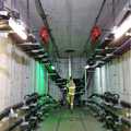
도 1은 지하 전력구의 사진이다.Figure 1 is a photograph of an underground electric power plant.
도 1에서 보는 바와 같이, 지하 전력구는 전력 통신용의 전선을 집합 수용하기 위한 공간을 통칭하는 것으로서, 사람이 직접 점검이나 보수를 할 수 있도록 터널 형태로 넓게 구성되어 있다.As shown in FIG. 1, the underground power section refers to a space for collecting electric wires for power communication, and is widely configured in a tunnel form so that a person can directly check or repair the same.
지하 전력구는 전봇대 아래에 구비되는 경우가 많고, 전봇대가 없는 도심에서는 1-2km마다 전력구가 수십개에서 수백개에 이른다. 이와 같이 수많은 지하 전력구는 그 점검과 유지/보수에만 상당한 인력과 시간이 요구된다.The underground electric power area is often installed under the electric pole, and in the city without the electric pole, the power electric power reaches from several tens to several hundreds per 1-2 km. In this way, many underground power stations require considerable manpower and time only for their inspection and maintenance.
그런데, 지하 전력구는 지하에 마련되므로, 장마나 홍수가 발생했을 때 우수에 의해 침수 피해를 입기 쉽다. 지하 전력구에 물이 차면 전력 문제가 발생할 수 있으며, 신속하게 배수 처리를 해줘야 한다.However, since the underground electric power area is provided in the basement, flood damage is likely to be caused by rainfall when rainy season or flood occurs. If there is water in the underground electric power plant, electric power problems may occur, and it is necessary to drain water quickly.
그래서 지하 전력구에는 항상 배수 펌프가 구비되어 있다. 그러나, 배수 펌프는 장마철이나 홍수가 발생하여 물이 찼을 때만 사용된다. 배수 펌프를 사용하는 빈도 수는 매우 낮다. 1년 내내 1번 정도 사용할 수도 있고 1번도 사용하지 않는 경우도 있다.Therefore, the underground electric power is always equipped with a drain pump. However, the drain pump is used only when the water is full due to a rainy season or a flood. The frequency of using a drainage pump is very low. It may be used once a year or may not be used once.
이에, 배수 펌프가 제대로 동작하는지 여부를 평상시에는 알 수 없는 경우가 많다. 정작 지하 전력구에 물이 찼을 때 배수 펌프 고장으로 인해 배수 처리를 제대로 하지 못하는 경우가 발생할 수 있다. 지하 전력구에는 예비 펌프가 구비되지 않는 경우가 대부분이므로, 배수 펌프의 고장으로 인해 심각한 피해를 초래할 수 있다.Therefore, it is often impossible to know whether or not the drain pump operates normally. In some cases, when the water in the underground electric power plant is filled, the drainage pump may fail to operate properly. In most cases, the auxiliary power pump is not equipped with an underground electric power source, so it may cause serious damage due to failure of the drain pump.
수많은 지하 전력구의 점검 자체가 매우 방대한 작업이며, 펌프의 이상 여부를 일일이 수작업으로 확인하는 것은 사실상 불가능하다.The inspection of many underground electric power facilities is a very large task, and it is practically impossible to manually check the abnormality of the pump.
배수 펌프는 주로 원격 센터(remote center)에서 원격 제어되는데, 원격 센터에서는 온/오프(on/off) 제어 명령을 통하여 배수 펌프를 턴온/턴오프(turn-on/turn-off)시키도록 구성된다. 그러나, 배수 펌프가 온/오프 제어에 의하여 제어가 되지만 실제 펌프가 동작되는지에 대한 피드백은 없이 스위치의 온/오프만 피드백되고 있다.The drain pump is mainly remotely controlled from a remote center where the remote center is configured to turn on / off the drain pump via an on / off control command . However, although the drain pump is controlled by on / off control, only the on / off of the switch is fed back without feedback as to whether the actual pump is operated.
배수 펌프의 온 버튼을 눌러도 배수 펌프가 턴온되지 않는다면, 지하 전력구에 물이 차서 전력 공급에 차질이 발생할 수 있다. 이에, 수많은 지하 전력구의 배수 펌프의 동작을 원격에서 확인하고 적절한 조치를 취할 수 있는 방안이 요구되고 있다.If the drain pump is not turned on by pressing the on button of the drain pump, there may be water in the underground power source, which may cause an interruption in the power supply. Therefore, there is a demand for a method of remotely checking the operation of drainage pumps of a number of underground power plants and taking appropriate measures.
본 발명의 목적은 지하 전력구 펌프 원격 진단 시스템을 제공하는 데 있다.It is an object of the present invention to provide an underground electric power pump remote diagnosis system.
본 발명의 다른 목적은 지하 전력구 펌프 원격 진단 방법을 제공하는 데 있다.Another object of the present invention is to provide a method for remote diagnosis of an underground electric power pump.
상술한 본 발명의 목적에 따른 지하 전력구 펌프 원격 진단 시스템은, 지하 전력구에 설치되어 원격 제어 명령에 동작하며, 상기 지하 전력구의 침수 시 배수 동작을 수행하는 배수 펌프; 상기 배수 펌프의 동작 전류를 측정하는 전류 센서 모듈; 상기 원격 제어 명령을 수신하여 상기 배수 펌프를 턴온(turn-on)시키거나 턴오프(turn-off)시키고, 상기 배수 펌프가 턴온되면 상기 전류 센서 모듈에서 측정되는 동작 전류를 실시간으로 송신하는 제어기; 상기 지하 전력구의 침수 시 상기 원격 제어 명령을 생성하여 상기 제어기로 송신하고, 상기 제어기로부터 동작 전류를 수신하여 상기 배수 펌프의 동작을 모니터링하는 원격 제어 단말을 포함하도록 구성될 수 있다.The above object of the present invention can be also achieved by a remote diagnosis system for an underground electric power pump, comprising: a drain pump installed in an underground electric power facility for operating a remote control command, A current sensor module for measuring an operation current of the drain pump; A controller that receives the remote control command to turn-on or turn off the drain pump and transmits an operating current measured by the current sensor module in real time when the drain pump is turned on; And a remote control terminal for generating the remote control command when the submersible power port is submerged, transmitting the remote control command to the controller, and monitoring an operation of the drain pump by receiving an operation current from the controller.
여기서, 상기 제어기는, 평상시에 간헐적으로 상기 배수 펌프의 동작 전류를 측정하여 상기 원격 제어 단말로 송신하고, 상기 배수 펌프의 턴온시에 상기 배수 펌프의 동작 전류를 측정하여 상기 원격 제어 단말로 실시간 송신하도록 구성될 수 있다.The controller measures the operating current of the drain pump intermittently at normal times and transmits the measured current to the remote control terminal. The controller measures the operating current of the drain pump at the time of turning on the drain pump, .
그리고 상기 원격 제어 단말은, 상기 제어기로부터 평상시의 동작 전류 및 턴온시의 동작 전류를 각각 수신하여 대비하고, 대비 결과 평상시의 동작 전류 및 턴온시의 동작 전류가 소정 임계치 이상 차이가 나는지 판단하고, 판단결과 소정 임계치 이상 차이가 나지 않으면 고장 내지는 동작 오류로 판단하여 보고하도록 구성될 수 있다.The remote control terminal receives and compares the normal operation current and the turn-on operation current from the controller, and determines whether the operation current at the time of normal contrast and the operation current at the turn-on time differ by not less than a predetermined threshold value, And if the difference does not exceed the predetermined threshold value, it is determined that a malfunction or an operation error is detected and reported.
상술한 본 발명의 다른 목적에 따른 지하 전력구 펌프 원격 진단 방법은, 전류 센서 모듈이 배수 펌프의 평상시의 동작 전류를 간헐적으로 측정하는 단계; 제어기가 상기 측정된 평상시의 동작 전류를 원격 제어 단말로 실시간 송신하고 상기 원격 제어 단말이 평상시의 동작 전류를 실시간 수신하는 단계; 지하 전력구의 침수시 상기 원격 제어 단말이 배수 펌프를 턴온(turn-on)하기 위한 원격 제어 명령을 생성하여 상기 제어기로 송신하는 단계; 상기 제어기가 원격 제어 명령을 수신하여 상기 배수 펌프를 턴온시키는 단계; 상기 배수 펌프가 턴온되어 배수 동작을 수행하는 단계; 상기 전류 센서 모듈이 상기 배수 펌프의 턴온시의 동작 전류를 측정하는 단계; 상기 제어기가 상기 측정된 턴온시의 동작 전류를 상기 원격 제어 단말로 실시간 송신하고, 상기 원격 제어 단말이 상기 턴온시의 동작 전류를 실시간 수신하는 단계; 상기 원격 제어 단말이 상기 평상시의 동작 전류와 상기 턴온시의 동작 전류를 대비하여 상기 배수 펌프의 고장 내지는 동작 오류를 판단하여 보고하는 단계를 포함하도록 구성될 수 있다.Another aspect of the present invention provides a method for remotely diagnosing an underground electric power pump pump, comprising the steps of intermittently measuring a normal operation current of a drain pump by a current sensor module; The controller real-time transmitting the measured normal operation current to the remote control terminal and receiving the normal operation current in real time by the remote control terminal; Generating a remote control command for turning on the drain pump when the submersible power supply is submerged and transmitting the remote control command to the controller; The controller receiving a remote control command to turn on the drain pump; Performing a drain operation by turning on the drain pump; Measuring the operating current of the current sensor module when the drain pump is turned on; The controller transmits the measured operating current at the time of turning on to the remote control terminal in real time and the remote control terminal receives the operating current when the remote control terminal is turned on in real time; And the remote control terminal judges and reports a failure or an operation error of the drain pump in comparison with the normal operation current and the operation current at the time of the turn-on.
여기서, 상기 원격 제어 단말이 상기 평상시의 동작 전류와 상기 턴온시의 동작 전류를 대비하여 상기 배수 펌프의 고장 내지는 동작 오류를 판단하여 보고하는 단계는, 상기 평상시의 동작 전류와 상기 턴온시의 동작 전류를 대비하여 평상시의 동작 전류 및 턴온시의 동작 전류가 소정 임계치 이상 차이가 나는지 판단하고, 판단 결과 소정 임계치 이상 차이가 나지 않으면 고장 내지는 동작 오류로 판단하도록 구성될 수 있다.Here, the step of the remote control terminal judging and reporting a failure or an operation error of the drain pump in comparison with the normal operation current and the operation current at the time of turning on may include the step of comparing the normal operation current and the operation current It is determined whether a normal operation current and an operation current at the time of turning on differ from a predetermined threshold value or not, and if the difference does not exceed a predetermined threshold value, it is determined that a failure or an operation error occurs.
상술한 지하 전력구 펌프 원격 진단 시스템 및 방법에 의하면, 평상시 배수 펌프의 동작 전류와 동작중인 배수 펌프의 동작 전류를 대비하여 배수 펌프의 정상 동작 여부를 원격에서 판단하도록 구성됨으로써, 고장이거나 동작에 오류가 있는 배수 펌프를 미리 점검하여 조치를 취할 수 있는 효과가 있다.According to the above-described underground electric power pump's remote diagnosis system and method, it is possible to remotely determine whether the drain pump is operating normally by comparing the operation current of the drain pump and the operation current of the drain pump in operation, There is an effect that it is possible to take a measure by checking the drain pump in advance.
또한, 배수 펌프의 동작 중에도 정상 동작 여부를 실시간 판단할 수 있기 때문에 배수 처리가 제대로 되고 있는지를 정확하게 파악하고 신속한 조치를 취할 수 있는 효과가 있다.In addition, since it is possible to determine in real time whether a normal operation is performed during operation of the drain pump, it is possible to precisely grasp whether the drainage process is being performed properly and to take prompt action.
한편, 수위 센서 모듈을 기압계의 기압 측정 원래를 변형하여 수위를 측정하도록 구성됨으로써, 기존의 오뚜기식 수위계가 경화되어 허위 알람을 발생시키는 문제점을 해결하는 효과가 있다. 또한, 수위 센서 모듈의 유지 및 보수가 용이하게 되는 장점이 있다.On the other hand, the water level sensor module is configured to measure the water level by modifying the barometric pressure measurement originally of the barometer, thereby solving the problem that the conventional water level meter is cured and a false alarm is generated. In addition, there is an advantage that maintenance and repair of the water level sensor module is facilitated.
다른 한편, 수많은 케이블 커넥터(cable connector)를 열화상 카메라 모듈을 이용하여 이상 고온을 감지하도록 구성됨으로써, 케이블 커넥터마다 온도 센서(10)를 부착하지 않아도 정확하게 다수의 케이블 커넥터에 대한 온도 감지를 할 수 있는 효과가 있다.On the other hand, since a large number of cable connectors are configured to detect abnormally high temperatures by using an infrared camera module, it is possible to accurately detect the temperature of a plurality of cable connectors without attaching the
도 1은 지하 전력구의 사진이다.
도 2는 본 발명의 일 실시예에 따른 지하 전력구 펌프 원격 진단 시스템의 블록 구성도이다.
도 3a는 지하 전력구의 케이블 커넥터를 나타내는 실물 사진이다.
도 3b는 종래 기술에 따른 케이블 커넥터에 부착되는 온도 센서의 모식도이다.
도 3c는 본 발명의 일 실시예에 따른 열화상 카메라의 온도 감시 동작을 나타내는 모식도이다.
도 4a는 종래 기술에 따른 오뚜기식 수위계의 동작을 나타내는 모식도이다.
도 4b는 본 발명의 일 실시예에 따른 수위 센서 모듈의 동작을 나타내는 모식도이다.
도 5는 본 발명의 일 실시예에 따른 지하 전력구 펌프 원격 진단 방법의 흐름도이다.Figure 1 is a photograph of an underground electric power plant.
2 is a block diagram of a remote diagnosis system for an underground electric power pump according to an embodiment of the present invention.
3A is a photograph showing a cable connector of an underground power port.
3B is a schematic diagram of a temperature sensor attached to a cable connector according to the prior art.
3C is a schematic diagram showing a temperature monitoring operation of the thermal imaging camera according to an embodiment of the present invention.
FIG. 4A is a schematic diagram showing the operation of a water level meter according to the prior art. FIG.
4B is a schematic view illustrating an operation of the water level sensor module according to an embodiment of the present invention.
5 is a flowchart of a remote diagnosis method of an underground electric power pump according to an embodiment of the present invention.
본 발명은 다양한 변경을 가할 수 있고 여러 가지 실시예를 가질 수 있는 바, 특정 실시 예들을 도면에 예시하고 발명을 실시하기 위한 구체적인 내용에 상세하게 설명하고자 한다. 그러나, 이는 본 발명을 특정한 실시 형태에 대해 한정하려는 것이 아니며, 본 발명의 사상 및 기술 범위에 포함되는 모든 변경, 균등물 내지 대체물을 포함하는 것으로 이해되어야 한다. 각 도면을 설명하면서 유사한 참조부호를 유사한 구성요소에 대해 사용하였다.While the invention is susceptible to various modifications and alternative forms, specific embodiments thereof are shown by way of example in the drawings and will herein be described in detail to the concrete inventive concept. It should be understood, however, that the invention is not intended to be limited to the particular embodiments, but includes all modifications, equivalents, and alternatives falling within the spirit and scope of the invention. Like reference numerals are used for like elements in describing each drawing.
제1, 제2, A, B 등의 용어는 다양한 구성요소들을 설명하는데 사용될 수 있지만, 상기 구성요소들은 상기 용어들에 의해 한정되어서는 안 된다. 상기 용어들은 하나의 구성요소를 다른 구성요소로부터 구별하는 목적으로만 사용된다. 예를 들어, 본 발명의 권리 범위를 벗어나지 않으면서 제1 구성요소는 제2 구성요소로 명명될 수 있고, 유사하게 제2 구성요소도 제1 구성요소로 명명될 수 있다. 및/또는 이라는 용어는 복수의 관련된 기재된 항목들의 조합 또는 복수의 관련된 기재된 항목들 중의 어느 항목을 포함한다.The terms first, second, A, B, etc. may be used to describe various elements, but the elements should not be limited by the terms. The terms are used only for the purpose of distinguishing one component from another. For example, without departing from the scope of the present invention, the first component may be referred to as a second component, and similarly, the second component may also be referred to as a first component. And / or < / RTI > includes any combination of a plurality of related listed items or any of a plurality of related listed items.
어떤 구성요소가 다른 구성요소에 "연결되어" 있다거나 "접속되어" 있다고 언급된 때에는, 그 다른 구성요소에 직접적으로 연결되어 있거나 또는 접속되어 있을 수도 있지만, 중간에 다른 구성요소가 존재할 수도 있다고 이해되어야 할 것이다. 반면에, 어떤 구성요소가 다른 구성요소에 "직접 연결되어" 있다거나 "직접 접속되어" 있다고 언급된 때에는, 중간에 다른 구성요소가 존재하지 않는 것으로 이해되어야 할 것이다.It is to be understood that when an element is referred to as being "connected" or "connected" to another element, it may be directly connected or connected to the other element, . On the other hand, when an element is referred to as being "directly connected" or "directly connected" to another element, it should be understood that there are no other elements in between.
본 출원에서 사용한 용어는 단지 특정한 실시예를 설명하기 위해 사용된 것으로, 본 발명을 한정하려는 의도가 아니다. 단수의 표현은 문맥상 명백하게 다르게 뜻하지 않는 한, 복수의 표현을 포함한다. 본 출원에서, "포함하다" 또는 "가지다" 등의 용어는 명세서상에 기재된 특징, 숫자, 단계, 동작, 구성요소, 부품 또는 이들을 조합한 것이 존재함을 지정하려는 것이지, 하나 또는 그 이상의 다른 특징들이나 숫자, 단계, 동작, 구성요소, 부품 또는 이들을 조합한 것들의 존재 또는 부가 가능성을 미리 배제하지 않는 것으로 이해되어야 한다.The terminology used in this application is used only to describe a specific embodiment and is not intended to limit the invention. The singular expressions include plural expressions unless the context clearly dictates otherwise. In the present application, the terms "comprises" or "having" and the like are used to specify that there is a feature, a number, a step, an operation, an element, a component or a combination thereof described in the specification, But do not preclude the presence or addition of one or more other features, integers, steps, operations, elements, components, or combinations thereof.
다르게 정의되지 않는 한, 기술적이거나 과학적인 용어를 포함해서 여기서 사용되는 모든 용어들은 본 발명이 속하는 기술 분야에서 통상의 지식을 가진 자에 의해 일반적으로 이해되는 것과 동일한 의미를 가지고 있다. 일반적으로 사용되는 사전에 정의되어 있는 것과 같은 용어들은 관련 기술의 문맥 상 가지는 의미와 일치하는 의미를 가지는 것으로 해석되어야 하며, 본 출원에서 명백하게 정의하지 않는 한, 이상적이거나 과도하게 형식적인 의미로 해석되지 않는다.Unless defined otherwise, all terms used herein, including technical or scientific terms, have the same meaning as commonly understood by one of ordinary skill in the art to which this invention belongs. Terms such as those defined in commonly used dictionaries are to be interpreted as having a meaning consistent with the contextual meaning of the related art and are to be interpreted as either ideal or overly formal in the sense of the present application Do not.
이하, 본 발명에 따른 바람직한 실시예를 첨부된 도면을 참조하여 상세하게 설명한다.Hereinafter, preferred embodiments according to the present invention will be described in detail with reference to the accompanying drawings.
도 2는 본 발명의 일 실시예에 따른 지하 전력구 펌프 원격 진단 시스템의 블록 구성도이다.2 is a block diagram of a remote diagnosis system for an underground electric power pump according to an embodiment of the present invention.
도 2를 참조하면, 본 발명의 일 실시예에 따른 지하 전력구 펌프 원격 진단 시스템(100)은 배수 펌프(110), 전류 센서 모듈(120), 열화상 카메라 모듈(130), 수위 센서 모듈(140), 제어기(150), 원격 제어 단말(160)을 포함하도록 구성될 수 있다.Referring to FIG. 2, an underground electric power source pump
지하 전력구 펌프 원격 진단 시스템(100)은 평상시 배수 펌프(110)의 동작 전류와 동작중인 배수 펌프(110)의 동작 전류를 원격에서 대비하여 배수 펌프(110)의 고장 여부나 동작 오류 여부를 판단할 수 있도록 구성된다.The underground electric power pump or pump
거의 동작하지 않고 침수시에만 동작하는 지하 전력구의 수많은 배수 펌프(110)에 대해 원격에서 점검이 가능하다.It is possible to remotely check a large number of
그리고 수위 센서 모듈(140)이 기압계의 기압 측정 원리를 활용하여 수압을 측정하고 이로부터 수위를 산출할 수 있도록 구성된다. 이에, 기존의 오래된 오뚜기식 수위계의 허위 알람을 방지하고 반영구적으로 수위를 정확하게 측정할 수 있게 된다.The water
그리고 케이블 커넥터(cable connector)(1)들에 대해 각각 온도 센서(10)를 부착할 필요없이 열화상 카메라 모듈(130)을 이용하여 다수의 케이블 커넥터(1)를 동시에 감시하도록 구성되어 수많은 케이블 커넥터(1)들에 대해 효율적인 온도 감시를 수행하도록 구성된다.And is configured to simultaneously monitor a plurality of
이하, 세부적인 구성에 대하여 설명한다.Hereinafter, the detailed configuration will be described.
배수 펌프(110)는 지하 전력구에 설치되어 원격 제어 단말(160)의 원격 제어 명령에 따라 동작하도록 구성될 수 있다. 물론, 지하 전력구 현장에서 배수 펌프(110)를 수동으로 동작시킬 수도 있다.The
배수 펌프(110)는 지하 전력구의 침수시 배수 동작을 수행하도록 구성될 수 있다. 주로, 장마철이나 홍수시에 지하 전력구가 침수되었을 때 동작한다.The
전류 센서 모듈(120)은 배수 펌프(110)의 동작 전류를 측정하도록 구성될 수 있다.The
전류 센서 모듈(120)은 배수 펌프(110)에 부착되는 구성으로서, 배수 펌프(110)의 구동을 위한 동작 전류를 측정하도록 구성될 수 있다. 동작 전류에 따라서 배수 펌프(110)의 실제 동작 여부를 알 수 있다.The
여기서, 전류 센서 모듈(120)은 배수 펌프(110)의 구동을 위한 동작 전류뿐만 아니라, 배수 펌프(110)의 회전 구동에 의한 회전 구동 전류를 측정하도록 구성될 수도 있다.Here, the
배수 펌프(110)의 회전 프로펠러의 회전 구동축에는 피에조(piezo) 소자가 구비될 수 있다. 피에조 소자는 회전 구동축의 회전면과 마찰을 하여 압력을 받도록 구성될 수 있으며, 이 압력에 의해 전기가 발생하도록 구성될 수 있다.The rotation driving shaft of the rotating propeller of the
전류 센서 모듈(120)은 피에조 소자에서 발생되는 전기를 측정하도록 구성될 수 있다. 피에조 소자에서 발생되는 전기를 측정하여 회전 구동축의 회전 속도를 가늠할 수 있으며, 이를 통해 배수 펌프(110)의 정상 동작 여부를 판단할 수 있다.The
배수 펌프(110)의 회전 구동축의 회전 운동에 의한 전기를 측정하는 경우 배수 펌프(110)의 동작 말단의 전기를 측정하는 것이기 대문에 배수 펌프(110)의 정상 동작 여부를 보다 정확하게 판단할 수 있는 장점이 있다.Since the electric power at the operation end of the
열화상 카메라 모듈(130)은 적외선 등을 감지하여 객체의 온도를 감지하도록 구성된다. 도 3a 내지 도 3b를 참조하여 열화상 카메라 모듈(130)에 대해 설명한다.The thermal
도 3a는 지하 전력구의 케이블 커넥터를 나타내는 실물 사진이다. 도 3a는 지하 전력구에 구비되는 수많은 케이블의 케이블 커넥터이다. 케이블들은 수십 km씩 이어져 연장되는데, 케이블 커넥터(1)에 의해 케이블들이 연결되어 연장된다. 여러 개의 케이블의 케이블 커넥터(1)는 유사 지점에서 함께 형성되는 예가 많다.3A is a photograph showing a cable connector of an underground power port. 3A is a cable connector for a number of cables provided in an underground power port. The cables extend for several tens of kilometers, and the cables are connected and extended by the
이러한 케이블 커넥터(1)는 저항이 커져서 발열이 많다는 단점이 있다. 화재 사고라든지 단선, 단락 등은 주로 케이블 커넥터(1)에서 발생하는 경우가 많다.This
도 3b는 종래 기술에 따른 케이블 커넥터에 부착되는 온도 센서의 모식도이다.3B is a schematic diagram of a temperature sensor attached to a cable connector according to the prior art.
도 3b에서 보듯이 종래에는 케이블 커넥터(1)의 발열을 감지하기 위해 각각의 케이블 커넥터(1)마다 온도 센서(10)를 부착하여 이상 발열을 감지하였다.As shown in FIG. 3B, in order to detect the heat generation of the
그런데, 수많은 케이블 커넥터(1)마다 온도 센서(10)를 부착하면 그 설치 및 보수에 상당한 비용과 시간이 소모되며, 온도 센서(10)에서 측정된 온도를 별도의 케이블을 통해 취합하여야 하므로 그 구성이 매우 복잡해진다.However, if a
도 3c는 본 발명의 일 실시예에 따른 열화상 카메라의 온도 감시 동작을 나타내는 모식도이다.3C is a schematic diagram showing a temperature monitoring operation of the thermal imaging camera according to an embodiment of the present invention.
도 3c에서 보듯이 본 발명에서는 열화상 카메라 모듈(130)을 이용하여 케이블 커넥터(1)들의 이상 발열을 한꺼번에 감시하도록 구성될 수 있다. 열화상 카메라 모듈(130)은 케이블 커넥터(1)들이 모여 있는 지점에 대해 적외선 촬영을 수행하여 케이블 커넥터(1)의 발열 여부를 실시간 감지하도록 구성될 수 있다.As shown in FIG. 3C, the present invention can be configured to simultaneously monitor abnormal heat generation of the
열화상 카메라 모듈(130)은 별도의 온도 센서(10)나 케이블없이 원격에서 여러 케이블 커넥터(1)를 한꺼번에 감시할 수 있으므로 매우 효율적이며 이상 발열의 감지에 대한 정확도도 매우 높다.The thermal
열화상 카메라 모듈(130)은 지하 전력구의 천장이나 윗벽면에 부착되도록 구성될 수 있다.The thermal
열화상 카메라 모듈(130)에서 감지되는 온도 또는 이상 발열 여부는 제어기(150)로 실시간 제공되며, 제어기(150)는 이를 원격 제어 단말(160)로 실시간 전달하도록 구성될 수 있다.The
열화상 카메라 모듈(130)은 현재 지점이나 발열 케이블 커넥터(1)를 특정하여 제어기(150)로 온도와 이상 발열 여부를 제공하도록 구성될 수 있다.The thermal
수위 센서 모듈(140)은 지하 전력구에 물이 차오를 때 수위를 측정하도록 하기 위한 구성이다. 이하, 도 4a 및 도 4b를 참조하여 수위 센서 모듈(140)에 대해 설명한다.The water
도 4a는 종래 기술에 따른 오뚜기식 수위계의 동작을 나타내는 모식도이다.FIG. 4A is a schematic diagram showing the operation of a water level meter according to the prior art. FIG.
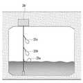
도 4a에서 보듯이 종래에는 지하 전력구의 곳곳에 오뚜기식 수위계를 설치하였다. 오뚜기식 수위계는 수위계(20)를 천장 부위에 설치하고, 수위계(20) 아래로 수직으로 줄을 늘어뜨리고 줄의 곳곳에 내부가 비어있는 플라스틱(plastic)이나 비닐(vinyl)로 구성되는 센서(21a, 21b, 21c)를 부착하도록 구성된다. 물이 차올라 수위가 높아질 때마다 센서(21a)가 위로 꺾여 올라가면서 수위를 감지하게 된다.As shown in FIG. 4A, a water meter of the Ottogi type was installed in various places in the underground power pool. The Ottogi type water level meter is provided with a
지하 전력구 곳곳에 수없이 많이 설치해야 하며, 상시 유지/보수가 쉽지 않다는 점 등을 고려하여 매우 간단하고 비용이 절감되는 수위계(20)를 채택하여 이용하고 있다. 그러나, 오랜 기간 사용하다 보면 플라스틱이나 비닐로 구성되는 센서(21a)가 경화되어 굳어지고 물이 빠져도 내려가지 않는 경우가 있다. 이러한 경우에는 허위 알람을 보내게 되며 수많은 지하 전력구에서 허위 알람으로 인한 헛걸음이 많아지거나 감시 효율성이 떨어지게 되는 문제점이 있다.The
도 4b는 본 발명의 일 실시예에 따른 수위 센서 모듈의 동작을 나타내는 모식도이다.4B is a schematic view illustrating an operation of the water level sensor module according to an embodiment of the present invention.
도 4b에서 보듯이 본 발명의 수위 센서 모듈(140)은 기압계의 기압 측정 원리를 활용하여 수위를 측정하도록 구성된다. 기존의 수위 측정 원리와는 전혀 다른 측정 원리를 갖고 있다. 기압 측정 원리에 따른 케이스(case)(141)가 구비되며, 지하 전력구에 물이 차오르게 되면 케이스(141)에도 물이 차오르면서 케이스(141) 내부의 공기를 압축하게 된다. 케이스(141) 내부의 공기의 압력은 케이스(141)에 부착된 기압계(142)가 측정하도록 구성될 수 있다. 물이 차오를수록 케이스(141) 내부의 공기의 압력은 더욱 올라가게 되며 기압계(142)에서는 더 높은 기압이 측정될 수 있다. 이는 수위가 높아짐에 따라 기압계(142)의 측정 압력도 함께 높아지는 것을 의미한다. 수위가 높아짐에 따라 변화하는 측정 압력의 관계를 미리 산출하여 수위를 산출하도록 구성될 수 있다.As shown in FIG. 4B, the water
수위 측정 알고리즘은 다양하게 설정될 수 있다.The water level measurement algorithm can be set in various ways.
먼저 평상시의 지하 전력구의 기압은 다소 변화가 있을 수 있는데, 수위 센서 모듈(140)은 평균적인 기압에서 수위가 0인 것으로 가정할 수 있다. 그리고 평균적인 기압보다 올라가면 수위가 올라가는 것으로 판단할 수 있다.First, the atmospheric pressure of the underground electric power source may be slightly changed. The water
다른 방식으로는, 지하 전력구의 기압은 늘 일정하지 않지만 그 변화폭이 크지 않을 것이라는 전제 하에 기압의 변화 속도가 갑자기 커지는 때를 수위가 높아지는 시점으로 판단하여 수위를 측정할 수도 있다.Alternatively, the pressure of the underground electric power is not always constant, but the water level may be measured based on the assumption that the rate of change of the atmospheric pressure suddenly increases at a time when the water level becomes high, assuming that the variation width is not large.
수위가 0인 것으로 판단되는 시점에서 기압의 변화폭에 따라 수위의 변화폭을 산출할 수 있다.The change width of the water level can be calculated according to the variation range of the atmospheric pressure when the water level is judged to be zero.
수위 센서 모듈(140)은 기압계(142)의 압력 또는 위와 같이 산출되는 수위를 제어기(150)로 실시간 제공하며, 제어기(150)는 이를 원격 제어 단말(160)로 실시간 송신하도록 구성될 수 있다.The water
제어기(150)는 원격 제어 단말(160)로부터 원격 제어 명령을 수신하며, 수신된 원격 제어 명령에 따라 배수 펌프(110)를 턴온(turn-on)시키거나 턴오프(turn-off)시키도록 구성될 수 있다.The
제어기(150)는 배수 펌프(110)가 턴온되거나 턴오프될 때 전류 센서 모듈(120)에서 측정되는 동작 전류를 원격 제어 단말(160)로 실시간 송신하도록 구성될 수 있다.The
제어기(150)는 평상시에는 간헐적으로 배수 펌프(110)의 동작 전류를 측정하여 원격 제어 단말(160)로 자동 송신하도록 구성되며, 배수 펌프(110)의 턴온시 또는 턴오프시 배수 펌프(110)의 동작 전류를 측정하여 원격 제어 단말(160)로 실시간 자동 송신하도록 구성될 수 있다. 제어기(150)는 평상시에 하루 1회 또는 1주일에 1회와 같이 미리 정해진 주기로 배수 펌프(110)의 동작 전류를 측정하도록 전류 센서 모듈(120)을 제어할 수 있다.The
제어기(150)는 전력 통신선을 통해 동작 전류를 원격 제어 단말(160)로 송신할 수 있으며, 원격 제어 단말(160) 역시 전력 통신선을 통해 원격 제어 명령을 제어기(150)로 송신하도록 구성될 수 있다.The
한편, 제어기(150)는 수위 센서 모듈(140)에서 수위가 기준치 이상으로 측정된 경우, 자동으로 배수 펌프(110)를 가동시키도록 구성될 수 있다. 물이 빠져서 수위가 내려가는 경우 자동으로 배수 펌프(110)의 동작을 중단시키도록 구성될 수 있다. 수위의 변화 속도를 측정하여 배수 펌프(110)의 가동율을 조절하도록 제어할 수 있다.Meanwhile, the
또한, 제어기(150)는 원격 제어 단말(160)의 원격 제어 명령에 따라 배수 펌프(110)의 동작을 제어하도록 구성될 수 있다.In addition, the
다른 한편, 제어기(150)는 콘트롤러(controller)와 하나의 콘트롤러가 제어하는 여러 개의 로컬 스테이션(local station)으로 분류될 수 있다. 지하 전력구의 광역에 매우 길게 설치되어 있으므로, 원격 제어 명령이나 센서값의 송수신시 상당한 데이터 손실이 발생할 수밖에 없다. 이에, 광케이블이나 이더넷에 의해 곳곳에 콘트롤러를 구비하고 콘트롤러가 관리하는 여러 개의 로컬 스테이션을 구비하여 데이터 손실을 줄이고 구역별로 제어를 쉽게할 수 있도록 구성될 수 있다.On the other hand, the
원격 제어 단말(160)은 원격지에서 지하 전력구의 배수 펌프(110)를 원격 제어하도록 구성될 수 있다.The
원격 제어 단말(160)은 관할 지역의 수많은 지하 전력구의 배수 펌프(110)를 모두 제어할 수 있으며, 지하 전력구의 침수시 원격 제어 명령을 생성하여 제어기(150)로 송신하도록 구성될 수 있다.The
원격 제어 단말(160)은 제어기(150)로부터 동작 전류를 수신하여 배수 펌프(110)의 실제 동작 여부를 실시간 모니터링하도록 구성될 수 있다.The
원격 제어 단말(160)은 제어기(150)로부터 평상시의 동작 전류 및 턴온시의 동작 전류를 각각 수신하여 대비하도록 구성될 수 있다.The
원격 제어 단말(160)은 위 대비 결과 평상시의 동작 전류 및 턴온시의 동작 전류가 소정 임계치 이상 차이가 나는지 판단하도록 구성될 수 있다. 평상시의 동작 전류와 턴온시의 동작 전류가 소정 임계치 이상 차이가 나지 않으면 고장 내지는 동작 오류로 판단하여 보고하도록 구성될 수 있다.The
동작 전류의 차이가 없는 경우에는 턴온시에 배수 펌프(110)가 전혀 동작하지 않는 것으로 판단할 수 있으며, 동작 전류의 차이가 소정 임계치 이하로서 미미한 경우에는 배수 펌프(110)의 펌핑 출력이 기준치에 미달하는 것으로 판단할 수 있다.If there is no difference in operating current, it can be determined that the
한편, 시험 운전시에는 원격지에서 테스트 명령을 송신하고 현장에서 점검을 하지 않는 경우가 많은데, 턴온 명령만 송신한 후 턴오프 명령을 송신하지 않고 계속 턴온 상태로 방치하는 경우가 종종 발생한다.On the other hand, there are many cases where a test command is transmitted from a remote place during a test operation and the inspection is not performed on the spot. In some cases, the turn-on command is transmitted and then the turn-off command is not transmitted.
이에, 원격 제어 단말(160)은 배수 펌프(110)의 시험 운전시에는 자동으로 턴온된후 30초 정도의 미리 정해진 시간 후에는 자동으로 턴오프되도록 하는 원격 제어 명령을 제어기(150)로 송신하도록 구성될 수 있다.The
원격 제어 단말(160)은 제어기(150)로부터 수위를 수신하고, 수위에 따라 배수 펌프(110)를 가동하도록 하는 원격 제어 명령을 생성하여 제어기(150)로 송신하도록 구성될 수 있다.The
도 5는 본 발명의 일 실시예에 따른 지하 전력구 펌프 원격 진단 방법의 흐름도이다.5 is a flowchart of a remote diagnosis method of an underground electric power pump according to an embodiment of the present invention.
도 5를 참조하면, 전류 센서 모듈(120)이 배수 펌프(110)의 평상시의 동작 전류를 간헐적으로 측정한다(S101).Referring to FIG. 5, the
다음으로, 제어기(150)가 측정된 평상시의 동작 전류를 원격 제어 단말(160)로 실시간 송신하고 원격 제어 단말(160)이 평상시의 동작 전류를 실시간 수신한다(S102).Next, the
다음으로, 지하 전력구의 침수시 원격 제어 단말(160)이 배수 펌프(110)를 턴온(turn-on)하기 위한 원격 제어 명령을 생성하여 제어기(150)로 송신한다(S103).Next, the
다음으로, 제어기(150)가 원격 제어 명령을 수신하여 배수 펌프(110)를 턴온시킨다(S104).Next, the
다음으로, 배수 펌프(110)가 턴온되어 배수 동작을 수행한다(S105).Next, the
다음으로, 전류 센서 모듈(120)이 배수 펌프(110)의 턴온시의 동작 전류를 측정한다(S106).Next, the
다음으로, 제어기(150)가 측정된 턴온시의 동작 전류를 원격 제어 단말(160)로 실시간 송신하고, 원격 제어 단말(160)이 턴온시의 동작 전류를 실시간 수신한다(S107).Next, the
다음으로, 원격 제어 단말(160)이 평상시의 동작 전류와 턴온시의 동작 전류를 대비하여 배수 펌프(110)의 고장 내지는 동작 오류를 판단하여 보고한다(S108).Next, the
이때, 원격 제어 단말(160)이 평상시의 동작 전류와 턴온시의 동작 전류를 대비하여 평상시의 동작 전류 및 턴온시의 동작 전류가 소정 임계치 이상 차이가 나는지 판단하도록 구성될 수 있다.At this time, the
그 판단 결과 소정 임계치 이상 차이가 나지 않으면 고장 내지는 동작 오류로 판단하도록 구성될 수 있다.And if it is determined that the difference is not larger than the predetermined threshold value, it is determined that the failure is an operation error.
이상 실시예를 참조하여 설명하였지만, 해당 기술 분야의 숙련된 당업자는 하기의 특허청구범위에 기재된 본 발명의 사상 및 영역으로부터 벗어나지 않는 범위 내에서 본 발명을 다양하게 수정 및 변경시킬 수 있음을 이해할 수 있을 것이다.It will be apparent to those skilled in the art that various modifications and variations can be made in the present invention without departing from the spirit or scope of the invention as defined in the following claims. There will be.
110: 배수 펌프
120: 전류 센서 모듈
130: 열화상 카메라 모듈
140: 수위 센서 모듈
141: 케이스
142: 기압계
150: 제어기
160: 원격 제어 단말110: Drain pump
120: Current sensor module
130: Thermal Imaging Camera Module
140: Level sensor module
141: Case
142: Barometer
150:
160: Remote control terminal
Claims (5)
Translated fromKorean상기 배수 펌프의 회전 구동 전류를 측정하는 전류 센서 모듈;
일단이 개방되고 타단이 밀폐된 장방형의 케이스(case) 및 상기 케이스의 타단 영역의 내부 안쪽에 기압계를 포함하며, 상기 개방된 일단이 아래쪽을 향하도록 배치되도록 구성되며, 상기 케이스의 개방된 일단을 통해 물이 차오르면 상기 기압계를 이용하여 상기 케이스 내부의 기압을 측정하는 수위 센서 모듈;
상기 지하 전력구의 천정에 설치되며, 양 케이블을 서로 연결하는 케이블 커넥터들을 적외선 촬영하여 상기 케이블 커넥터의 온도를 감지하는 열화상 카메라 모듈;
상기 원격 제어 명령을 수신하여 상기 배수 펌프를 턴온(turn-on)시키거나 턴오프(turn-off)시키고, 상기 배수 펌프가 턴온되면 상기 전류 센서 모듈에서 측정되는 회전 구동 전류, 상기 수위 센서 모듈에 의해 측정된 기압 및 상기 열화상 카메라 모듈에 의해 감지된 온도를 실시간으로 송신하는 제어기;
상기 제어기로부터 회전 구동 전류, 기압 및 온도를 수신하여 상기 배수 펌프의 동작을 모니터링하고, 상기 회전 구동 전류에 의해 상기 배수 펌프의 정상 동작 여부를 판단하고, 상기 기압에 의해 상기 지하 전력구의 수위를 감지하고, 상기 온도에 의해 상기 케이블 커넥터의 열화를 감지하고, 상기 지하 전력구의 침수 여부를 판단하고 판단 결과 침수시 상기 원격 제어 명령을 생성하여 상기 제어기로 송신하는 원격 제어 단말을 포함하고,
상기 전류 센서 모듈은,
상기 배수 펌프의 회전 프로펠러(propeller)의 회전 구동축에 부착되는 피에조 소자(piezzo element)를 포함하며, 상기 피에조 소자가 상기 회전 구동축의 회전면과의 마찰에 의한 압력에 의해 생기는 전류를 측정하고, 측정된 전류에 의해 상기 회전 구동축의 회전 속도를 산출하여 상기 배수 펌프의 회전 구동 전류를 측정하도록 구성되고,
상기 원격 제어 단말은,
상기 배수 펌프를 원격 제어하여 주기적으로 구동하고, 주기적 구동시 상기 전류 센서 모듈에 의해 측정되는 회전 구동 전류와 침수시 상기 전류 센서 모듈에 의해 측정되는 회전 구동 전류를 대비하여 소정 임계치 이상 차이가 나는지 판단하고, 판단 결과 소정 임계치 이상 차이가 나지 않으면 고장 내지는 동작 오류로 판단하여 보고하도록 구성되는 것을 특징으로 하는 지하 전력구 펌프 원격 진단 시스템.A drain pump installed in an underground power port to operate in a remote control command and perform a drain operation when the underground power port is submerged;
A current sensor module for measuring a rotational driving current of the drain pump;
A case having a rectangular shape with one end being opened and an other end being closed and a barometer on the inside of the other end area of the case, the open end being arranged to face downward, A water level sensor module for measuring a pressure of the inside of the case using the barometer when the water rises through the water level sensor module;
An infrared camera module installed on a ceiling of the underground power port and sensing the temperature of the cable connector by taking an infrared ray of the cable connectors connecting the both cables to each other;
The control unit receives the remote control command to turn-on or turn off the drain pump. When the drain pump is turned on, a rotation driving current measured by the current sensor module, A controller for transmitting in real time the atmospheric pressure measured by the infrared camera module and the temperature sensed by the thermal imaging camera module;
A controller for receiving the rotation driving current, the atmospheric pressure, and the temperature from the controller to monitor the operation of the drain pump, determining whether the drain pump is operating normally by the rotation driving current, And a remote control terminal for detecting deterioration of the cable connector by the temperature, determining whether the underground power port is submerged, generating a remote control command upon immersion, and transmitting the remote control command to the controller,
The current sensor module includes:
And a piezzo element attached to a rotating driving shaft of a rotating propeller of the drain pump, wherein the current generated by the pressure caused by the friction of the piezo element with the rotating surface of the rotating driving shaft is measured, And a rotation drive current of the drain pump is measured by calculating a rotation speed of the rotation drive shaft by a current,
The remote control terminal,
The drain pump is remotely controlled to periodically drive to determine whether a rotational driving current measured by the current sensor module during periodic driving and a rotational driving current measured by the current sensor module during immersion are greater than or equal to a predetermined threshold value And if it is determined that there is no difference by more than a predetermined threshold value, it is judged as a failure or an operation error and is reported.
Priority Applications (1)
| Application Number | Priority Date | Filing Date | Title |
|---|---|---|---|
| KR1020170062445AKR101791426B1 (en) | 2017-05-19 | 2017-05-19 | System and method of remote diagnosis for pump of underground electric ditch |
Applications Claiming Priority (1)
| Application Number | Priority Date | Filing Date | Title |
|---|---|---|---|
| KR1020170062445AKR101791426B1 (en) | 2017-05-19 | 2017-05-19 | System and method of remote diagnosis for pump of underground electric ditch |
Publications (1)
| Publication Number | Publication Date |
|---|---|
| KR101791426B1true KR101791426B1 (en) | 2017-10-31 |
Family
ID=60301589
Family Applications (1)
| Application Number | Title | Priority Date | Filing Date |
|---|---|---|---|
| KR1020170062445AActiveKR101791426B1 (en) | 2017-05-19 | 2017-05-19 | System and method of remote diagnosis for pump of underground electric ditch |
Country Status (1)
| Country | Link |
|---|---|
| KR (1) | KR101791426B1 (en) |
Cited By (4)
| Publication number | Priority date | Publication date | Assignee | Title |
|---|---|---|---|---|
| KR102051128B1 (en)* | 2019-10-04 | 2019-12-02 | 주식회사 제이에스엔지니어링 | System and method for real-time monitoring of underwater pump condition |
| KR20200069754A (en)* | 2018-12-07 | 2020-06-17 | 한전케이디엔주식회사 | Control system for power tunnel |
| KR20210114114A (en)* | 2020-03-10 | 2021-09-23 | 한국전력공사 | An integrated control panel for under ground power tunnel and operating method thereof |
| KR20220029953A (en)* | 2020-09-02 | 2022-03-10 | (주) 오토이노텍 | Underground drain pump management device |
Citations (1)
| Publication number | Priority date | Publication date | Assignee | Title |
|---|---|---|---|---|
| KR101228415B1 (en)* | 2012-09-11 | 2013-01-31 | 화랑시스템(주) | Water pump system for drainage and control method of water pump using this |
- 2017
- 2017-05-19KRKR1020170062445Apatent/KR101791426B1/enactiveActive
Patent Citations (1)
| Publication number | Priority date | Publication date | Assignee | Title |
|---|---|---|---|---|
| KR101228415B1 (en)* | 2012-09-11 | 2013-01-31 | 화랑시스템(주) | Water pump system for drainage and control method of water pump using this |
Cited By (7)
| Publication number | Priority date | Publication date | Assignee | Title |
|---|---|---|---|---|
| KR20200069754A (en)* | 2018-12-07 | 2020-06-17 | 한전케이디엔주식회사 | Control system for power tunnel |
| KR102168490B1 (en)* | 2018-12-07 | 2020-10-21 | 한전케이디엔주식회사 | Control system for power tunnel |
| KR102051128B1 (en)* | 2019-10-04 | 2019-12-02 | 주식회사 제이에스엔지니어링 | System and method for real-time monitoring of underwater pump condition |
| KR20210114114A (en)* | 2020-03-10 | 2021-09-23 | 한국전력공사 | An integrated control panel for under ground power tunnel and operating method thereof |
| KR102771213B1 (en)* | 2020-03-10 | 2025-02-25 | 한국전력공사 | An integrated control panel for under ground power tunnel and operating method thereof |
| KR20220029953A (en)* | 2020-09-02 | 2022-03-10 | (주) 오토이노텍 | Underground drain pump management device |
| KR102476180B1 (en)* | 2020-09-02 | 2022-12-12 | (주) 오토이노텍 | Underground drain pump management device |
Similar Documents
| Publication | Publication Date | Title |
|---|---|---|
| KR101791426B1 (en) | System and method of remote diagnosis for pump of underground electric ditch | |
| KR102065351B1 (en) | System of monitoring photovoltaic power generation | |
| KR102409193B1 (en) | Solar power generating system having string status monitoring, abnormal vibration and leakage current detection functions | |
| KR102084784B1 (en) | Method for managing the operation of Photovoltaic Power Generation based on machine learning | |
| US4232530A (en) | Heat pump system compressor start fault detector | |
| AU2011101045B4 (en) | Method and apparatus for monitoring a condition of a meter | |
| KR20200059704A (en) | System of monitoring photovoltaic power generation using failure prediction algorithm | |
| US9660574B2 (en) | System and method for adjusting notifications for solar monitoring systems | |
| KR101314089B1 (en) | Unmanned control system for equpiment and the control method | |
| CN107179739B (en) | A kind of greenhouse facilities fault detection system and method | |
| KR101493356B1 (en) | flood warning apparatus for a sedment control dam | |
| KR20200059706A (en) | System of monitoring photovoltaic power generation using weather data | |
| CN110671610A (en) | Monitoring system and monitoring method for heat supply pipeline | |
| KR20130052137A (en) | Remote monitoring system for solar cell problem | |
| KR102084783B1 (en) | System for managing the operation of Photovoltaic Power Generation based on machine learning | |
| CN111476385A (en) | Building facility maintenance supervisory systems based on BIM | |
| KR101410333B1 (en) | System and method for monitering of solar cell | |
| JP5258364B2 (en) | Photovoltaic power generation system, photovoltaic module fault detection method, photovoltaic module control circuit | |
| CN210742535U (en) | Terminal box microclimate monitoring system | |
| CN110671989B (en) | Control system based on bridge jacking intelligence double displacement sensor | |
| KR101418086B1 (en) | Roof-attached photovoltaic generating system that having a malfunction self-diagnosis function | |
| KR102419330B1 (en) | Apparatus and method for diagnosing error of the solar module | |
| KR20230088547A (en) | Electric Power Based Safety Management System | |
| CN211318085U (en) | On-site detection device and system for realizing maintenance-free gas density relay | |
| KR20210085034A (en) | Photovoltaic power generation monitoring system using wireless dongle |
Legal Events
| Date | Code | Title | Description |
|---|---|---|---|
| PA0109 | Patent application | St.27 status event code:A-0-1-A10-A12-nap-PA0109 | |
| PA0201 | Request for examination | St.27 status event code:A-1-2-D10-D11-exm-PA0201 | |
| PA0302 | Request for accelerated examination | St.27 status event code:A-1-2-D10-D17-exm-PA0302 St.27 status event code:A-1-2-D10-D16-exm-PA0302 | |
| D13-X000 | Search requested | St.27 status event code:A-1-2-D10-D13-srh-X000 | |
| D14-X000 | Search report completed | St.27 status event code:A-1-2-D10-D14-srh-X000 | |
| PE0902 | Notice of grounds for rejection | St.27 status event code:A-1-2-D10-D21-exm-PE0902 | |
| E13-X000 | Pre-grant limitation requested | St.27 status event code:A-2-3-E10-E13-lim-X000 | |
| P11-X000 | Amendment of application requested | St.27 status event code:A-2-2-P10-P11-nap-X000 | |
| P13-X000 | Application amended | St.27 status event code:A-2-2-P10-P13-nap-X000 | |
| E701 | Decision to grant or registration of patent right | ||
| PE0701 | Decision of registration | St.27 status event code:A-1-2-D10-D22-exm-PE0701 | |
| GRNT | Written decision to grant | ||
| PR0701 | Registration of establishment | St.27 status event code:A-2-4-F10-F11-exm-PR0701 | |
| PR1002 | Payment of registration fee | St.27 status event code:A-2-2-U10-U11-oth-PR1002 Fee payment year number:1 | |
| PG1601 | Publication of registration | St.27 status event code:A-4-4-Q10-Q13-nap-PG1601 | |
| PR1001 | Payment of annual fee | St.27 status event code:A-4-4-U10-U11-oth-PR1001 Fee payment year number:4 | |
| PR1001 | Payment of annual fee | St.27 status event code:A-4-4-U10-U11-oth-PR1001 Fee payment year number:5 | |
| PR1001 | Payment of annual fee | St.27 status event code:A-4-4-U10-U11-oth-PR1001 Fee payment year number:6 | |
| PR1001 | Payment of annual fee | St.27 status event code:A-4-4-U10-U11-oth-PR1001 Fee payment year number:7 | |
| R18-X000 | Changes to party contact information recorded | St.27 status event code:A-5-5-R10-R18-oth-X000 | |
| PR1001 | Payment of annual fee | St.27 status event code:A-4-4-U10-U11-oth-PR1001 Fee payment year number:8 | |
| PR1001 | Payment of annual fee | St.27 status event code:A-4-4-U10-U11-oth-PR1001 Fee payment year number:9 |