KR101790523B1 - Apparatus and method of transmitting control information in wireless communication system - Google Patents
Apparatus and method of transmitting control information in wireless communication systemDownload PDFInfo
- Publication number
- KR101790523B1 KR101790523B1KR1020100129070AKR20100129070AKR101790523B1KR 101790523 B1KR101790523 B1KR 101790523B1KR 1020100129070 AKR1020100129070 AKR 1020100129070AKR 20100129070 AKR20100129070 AKR 20100129070AKR 101790523 B1KR101790523 B1KR 101790523B1
- Authority
- KR
- South Korea
- Prior art keywords
- modulation symbol
- symbol
- control information
- modulation
- fdma symbols
- Prior art date
- Legal status (The legal status is an assumption and is not a legal conclusion. Google has not performed a legal analysis and makes no representation as to the accuracy of the status listed.)
- Expired - Fee Related
Links
Images


Classifications
- H—ELECTRICITY
- H04—ELECTRIC COMMUNICATION TECHNIQUE
- H04L—TRANSMISSION OF DIGITAL INFORMATION, e.g. TELEGRAPHIC COMMUNICATION
- H04L5/00—Arrangements affording multiple use of the transmission path
- H04L5/003—Arrangements for allocating sub-channels of the transmission path
- H04L5/0053—Allocation of signalling, i.e. of overhead other than pilot signals
- H—ELECTRICITY
- H04—ELECTRIC COMMUNICATION TECHNIQUE
- H04J—MULTIPLEX COMMUNICATION
- H04J11/00—Orthogonal multiplex systems, e.g. using WALSH codes
- H—ELECTRICITY
- H04—ELECTRIC COMMUNICATION TECHNIQUE
- H04J—MULTIPLEX COMMUNICATION
- H04J13/00—Code division multiplex systems
- H04J13/0007—Code type
- H04J13/0055—ZCZ [zero correlation zone]
- H04J13/0059—CAZAC [constant-amplitude and zero auto-correlation]
- H—ELECTRICITY
- H04—ELECTRIC COMMUNICATION TECHNIQUE
- H04L—TRANSMISSION OF DIGITAL INFORMATION, e.g. TELEGRAPHIC COMMUNICATION
- H04L27/00—Modulated-carrier systems
- H04L27/26—Systems using multi-frequency codes
- H04L27/2601—Multicarrier modulation systems
- H04L27/2626—Arrangements specific to the transmitter only
- H04L27/2627—Modulators
- H04L27/2634—Inverse fast Fourier transform [IFFT] or inverse discrete Fourier transform [IDFT] modulators in combination with other circuits for modulation
- H04L27/2636—Inverse fast Fourier transform [IFFT] or inverse discrete Fourier transform [IDFT] modulators in combination with other circuits for modulation with FFT or DFT modulators, e.g. standard single-carrier frequency-division multiple access [SC-FDMA] transmitter or DFT spread orthogonal frequency division multiplexing [DFT-SOFDM]
- H—ELECTRICITY
- H04—ELECTRIC COMMUNICATION TECHNIQUE
- H04L—TRANSMISSION OF DIGITAL INFORMATION, e.g. TELEGRAPHIC COMMUNICATION
- H04L5/00—Arrangements affording multiple use of the transmission path
- H04L5/0001—Arrangements for dividing the transmission path
- H04L5/0003—Two-dimensional division
- H04L5/0005—Time-frequency
- H04L5/0007—Time-frequency the frequencies being orthogonal, e.g. OFDM(A) or DMT
- H04L5/001—Time-frequency the frequencies being orthogonal, e.g. OFDM(A) or DMT the frequencies being arranged in component carriers
- H—ELECTRICITY
- H04—ELECTRIC COMMUNICATION TECHNIQUE
- H04L—TRANSMISSION OF DIGITAL INFORMATION, e.g. TELEGRAPHIC COMMUNICATION
- H04L5/00—Arrangements affording multiple use of the transmission path
- H04L5/0001—Arrangements for dividing the transmission path
- H04L5/0014—Three-dimensional division
- H04L5/0016—Time-frequency-code
- H—ELECTRICITY
- H04—ELECTRIC COMMUNICATION TECHNIQUE
- H04L—TRANSMISSION OF DIGITAL INFORMATION, e.g. TELEGRAPHIC COMMUNICATION
- H04L5/00—Arrangements affording multiple use of the transmission path
- H04L5/0001—Arrangements for dividing the transmission path
- H04L5/0014—Three-dimensional division
- H04L5/0023—Time-frequency-space
- H—ELECTRICITY
- H04—ELECTRIC COMMUNICATION TECHNIQUE
- H04L—TRANSMISSION OF DIGITAL INFORMATION, e.g. TELEGRAPHIC COMMUNICATION
- H04L5/00—Arrangements affording multiple use of the transmission path
- H04L5/003—Arrangements for allocating sub-channels of the transmission path
- H04L5/0044—Allocation of payload; Allocation of data channels, e.g. PDSCH or PUSCH
- H04L5/0046—Determination of the number of bits transmitted on different sub-channels
- H—ELECTRICITY
- H04—ELECTRIC COMMUNICATION TECHNIQUE
- H04L—TRANSMISSION OF DIGITAL INFORMATION, e.g. TELEGRAPHIC COMMUNICATION
- H04L5/00—Arrangements affording multiple use of the transmission path
- H04L5/003—Arrangements for allocating sub-channels of the transmission path
- H04L5/0048—Allocation of pilot signals, i.e. of signals known to the receiver
- H—ELECTRICITY
- H04—ELECTRIC COMMUNICATION TECHNIQUE
- H04L—TRANSMISSION OF DIGITAL INFORMATION, e.g. TELEGRAPHIC COMMUNICATION
- H04L5/00—Arrangements affording multiple use of the transmission path
- H04L5/003—Arrangements for allocating sub-channels of the transmission path
- H04L5/0053—Allocation of signalling, i.e. of overhead other than pilot signals
- H04L5/0055—Physical resource allocation for ACK/NACK
- H—ELECTRICITY
- H04—ELECTRIC COMMUNICATION TECHNIQUE
- H04L—TRANSMISSION OF DIGITAL INFORMATION, e.g. TELEGRAPHIC COMMUNICATION
- H04L5/00—Arrangements affording multiple use of the transmission path
- H04L5/003—Arrangements for allocating sub-channels of the transmission path
- H04L5/0053—Allocation of signalling, i.e. of overhead other than pilot signals
- H04L5/0057—Physical resource allocation for CQI
Landscapes
- Engineering & Computer Science (AREA)
- Signal Processing (AREA)
- Computer Networks & Wireless Communication (AREA)
- Physics & Mathematics (AREA)
- Discrete Mathematics (AREA)
- General Physics & Mathematics (AREA)
- Mathematical Physics (AREA)
- Power Engineering (AREA)
- Mobile Radio Communication Systems (AREA)
Abstract
Translated fromKoreanDescription
Translated fromKorean본 발명은 무선 통신 시스템에 관한 것으로, 보다 상세하게는 제어 정보를 전송하는 방법 및 장치에 관한 것이다. 무선 통신 시스템은 캐리어 병합(Carrier Aggregation: CA)을 지원할 수 있다.The present invention relates to a wireless communication system, and more particularly, to a method and apparatus for transmitting control information. The wireless communication system may support Carrier Aggregation (CA).
무선 통신 시스템이 음성이나 데이터 등과 같은 다양한 종류의 통신 서비스를 제공하기 위해 광범위하게 전개되고 있다. 일반적으로 무선통신 시스템은 가용한 시스템 자원(대역폭, 전송 파워 등)을 공유하여 다중 사용자와의 통신을 지원할 수 있는 다중 접속(multiple access) 시스템이다. 다중 접속 시스템의 예들로는 CDMA(code division multiple access) 시스템, FDMA(frequency division multiple access) 시스템, TDMA(time division multiple access) 시스템, OFDMA(orthogonal frequency division multiple access) 시스템, SC-FDMA(single carrier frequency division multiple access) 시스템 등이 있다.Background of the Invention [0002] Wireless communication systems are widely deployed to provide various types of communication services such as voice and data. Generally, a wireless communication system is a multiple access system capable of supporting communication with multiple users by sharing available system resources (bandwidth, transmission power, etc.). Examples of multiple access systems include a code division multiple access (CDMA) system, a frequency division multiple access (FDMA) system, a time division multiple access (TDMA) system, an orthogonal frequency division multiple access (OFDMA) system, a single carrier frequency division multiple access) systems.
본 발명의 목적은 무선 통신 시스템에서 제어 정보를 효율적으로 전송하는 방법 및 이를 위한 장치를 제공하는데 있다. 본 발명의 다른 목적은 제어 정보를 효율적으로 전송하기 위한 채널 포맷, 신호 처리, 및 이를 위한 장치를 제공하는데 있다. 본 발명의 또 다른 목적은 제어 정보를 전송하기 위한 자원을 효율적으로 할당하는 방법 및 이를 위한 장치를 제공하는데 있다.It is an object of the present invention to provide a method and apparatus for efficiently transmitting control information in a wireless communication system. It is another object of the present invention to provide a channel format, signal processing, and apparatus for efficiently transmitting control information. It is still another object of the present invention to provide a method and apparatus for efficiently allocating resources for transmitting control information.
본 발명에서 이루고자 하는 기술적 과제들은 상기 기술적 과제로 제한되지 않으며, 언급하지 않은 또 다른 기술적 과제들은 아래의 기재로부터 본 발명이 속하는 기술분야에서 통상의 지식을 가진 자에게 명확하게 이해될 수 있을 것이다.The technical problems to be solved by the present invention are not limited to the technical problems and other technical problems which are not mentioned can be understood by those skilled in the art from the following description.
본 발명의 일 양상으로, 무선 통신 시스템에서 단말이 PUCCH(Physical Uplink Control Channel)를 통해 제어 정보를 전송하는 방법에 있어서, 상기 제어 정보로부터 제1 변조 심볼과 제2 변조 심볼을 얻는 단계; 상기 제1 변조 심볼을 주파수 도메인에서 복수의 부반송파로 확산하는 단계; 상기 주파수 영역에서 확산된 제1 변조 심볼을 시간 도메인에서 복수의 인접한 제1 SC-FDMA 심볼로 확산하는 단계; 상기 제2 변조 심볼을 주파수 도메인에서 복수의 부반송파로 확산하는 단계; 상기 주파수 영역에서 확산된 제2 변조 심볼을 시간 도메인에서 복수의 인접한 제2 SC-FDMA 심볼로 확산하는 단계; 및 상기 확산된 제1 변조 심볼과 상기 확산된 제2 변조 심볼을 상기 PUCCH를 통해 전송하는 단계를 포함하고, 상기 복수의 인접한 제1 SC-FDMA 심볼과 상기 복수의 인접한 제2 SC-FDMA 심볼은 동일한 슬롯에 위치하는, 제어 정보 전송 방법이 제공된다.According to an aspect of the present invention, there is provided a method for transmitting control information through a Physical Uplink Control Channel (PUCCH) in a wireless communication system, the method comprising: obtaining a first modulation symbol and a second modulation symbol from the control information; Spreading the first modulation symbol in a frequency domain to a plurality of subcarriers; Spreading a first modulation symbol spread in the frequency domain to a plurality of adjacent first SC-FDMA symbols in a time domain; Spreading the second modulation symbol in a frequency domain to a plurality of subcarriers; Spreading a second modulation symbol spread in the frequency domain to a plurality of adjacent second SC-FDMA symbols in a time domain; And transmitting the spread first modulated symbol and the spread second modulated symbol on the PUCCH, wherein the plurality of adjacent first SC-FDMA symbols and the plurality of adjacent second SC- A method of transmitting control information, which is located in the same slot, is provided.
본 발명의 다른 양상으로, 무선 통신 시스템에서 PUCCH(Physical Uplink Control Channel)를 통해 제어 정보를 전송하도록 구성된 단말에 있어서, RF(Radio Frequency) 유닛; 및 프로세서를 포함하고, 상기 프로세서는 상기 제어 정보로부터 제1 변조 심볼과 제2 변조 심볼을 얻고, 상기 제1 변조 심볼을 주파수 도메인에서 복수의 부반송파로 확산하며, 상기 주파수 영역에서 확산된 제1 변조 심볼을 시간 도메인에서 복수의 인접한 제1 SC-FDMA 심볼로 확산하고, 상기 제2 변조 심볼을 주파수 도메인에서 복수의 부반송파로 확산하며, 상기 주파수 영역에서 확산된 제2 변조 심볼을 시간 도메인에서 복수의 인접한 제2 SC-FDMA 심볼로 확산하고, 상기 확산된 제1 변조 심볼과 상기 확산된 제2 변조 심볼을 상기 PUCCH를 통해 전송하도록 구성되고, 상기 복수의 인접한 제1 SC-FDMA 심볼과 상기 복수의 인접한 제2 SC-FDMA 심볼은 동일한 슬롯에 위치하는, 단말이 제공된다.According to another aspect of the present invention, there is provided a UE configured to transmit control information through a Physical Uplink Control Channel (PUCCH) in a wireless communication system, the UE comprising: a Radio Frequency (RF) unit; And a processor, wherein the processor obtains a first modulation symbol and a second modulation symbol from the control information, spreads the first modulation symbol in a frequency domain with a plurality of subcarriers, Spreading a second modulation symbol with a plurality of adjacent first SC-FDMA symbols in a time domain, spreading the second modulation symbol with a plurality of sub-carriers in a frequency domain, and transmitting a second modulation symbol spread in the frequency domain with a plurality of And to transmit the spread first modulated symbol and the spread second modulated symbol on the PUCCH, wherein the plurality of adjacent first SC-FDMA symbols and the plurality of And the adjacent second SC-FDMA symbols are located in the same slot.
여기에서, 상기 제1 변조 심볼과 상기 제2 변조 심볼은 채널 코딩된 제어 정보로부터 얻어질 수 있다.Here, the first modulation symbol and the second modulation symbol may be obtained from channel coded control information.
여기에서, 상기 제어 정보는 복수의 제어 정보를 포함하고, 상기 제1 변조 심볼과 상기 제2 변조 심볼은 조인트 코딩을 통해 생성된 단일 코드워드로부터 얻어질 수 있다.Here, the control information includes a plurality of control information, and the first modulation symbol and the second modulation symbol may be obtained from a single code word generated through joint coding.
여기에서, 상기 제1 변조 심볼은 상기 복수의 인접한 제1 SC-FDMA 심볼 내에 점유된 복수의 자원 중 어느 하나를 이용하여 전송되고, 상기 제2 변조 심볼은 상기 복수의 인접한 제2 SC-FDMA 심볼 내에 점유된 복수의 자원 중 어느 하나를 이용하여 전송될 수 있다.Wherein the first modulation symbol is transmitted using any one of a plurality of resources occupied in the plurality of adjacent first SC-FDMA symbols, and the second modulation symbol is transmitted using the plurality of adjacent second SC- FDMA symbols Lt; / RTI > may be transmitted using any one of a plurality of resources occupied within the network.
여기에서, 상기 제1 또는 제2 변조 심볼을 위해 점유된 복수의 자원 중에서 제1 자원에 관한 인덱스는 PDCCH(Physical Downlink Control Channel) 전송에 사용되는 CCE(Control Channel Element) 인덱스로부터 결정되고, 제2 자원에 관한 인덱스는 상기 제1 자원에 관한 인덱스와 오프셋 값으로부터 결정될 수 있다.Here, an index of a first resource among a plurality of resources occupied for the first or second modulation symbol is determined from a CCE (Control Channel Element) index used for Physical Downlink Control Channel (PDCCH) transmission, An index on a resource may be determined from an index and an offset value for the first resource.
여기에서, 상기 제1 변조 심볼 및 상기 제2 변조 심볼의 시간 도메인 확산에 사용되는 시퀀스는 SF(Spreading Factor)가 2일 수 있다.Here, the sequence used for the time domain spreading of the first modulation symbol and the second modulation symbol may be SF (Spreading Factor) 2.
여기에서, 상기 제1 변조 심볼과 상기 제2 변조 심볼의 주파수 도메인 확산에 사용되는 시퀀스는 CAZAC(Constant Amplitude Zero Auto Correlation) 시퀀스 또는 CG(Computer Generated)-CAZAC 시퀀스를 포함할 수 있다.Here, the sequence used for the frequency domain spreading of the first modulation symbol and the second modulation symbol may include a Constant Amplitude Zero Auto Correlation (CAZAC) sequence or a CG (Computer Generated) -CAZAC sequence.
본 발명에 의하면, 무선 통신 시스템에서 제어 정보를 효율적으로 전송할 수 있다. 또한, 제어 정보를 효율적으로 전송하기 위한 채널 포맷, 신호 처리 방법을 제공할 수 있다. 또한, 제어 정보 전송을 위한 자원을 효율적으로 할당할 수 있다.According to the present invention, it is possible to efficiently transmit control information in a wireless communication system. Further, it is possible to provide a channel format and a signal processing method for efficiently transmitting control information. In addition, resources for control information transmission can be efficiently allocated.
본 발명에서 얻은 수 있는 효과는 이상에서 언급한 효과들로 제한되지 않으며, 언급하지 않은 또 다른 효과들은 아래의 기재로부터 본 발명이 속하는 기술분야에서 통상의 지식을 가진 자에게 명확하게 이해될 수 있을 것이다.The effects obtained by the present invention are not limited to the above-mentioned effects, and other effects not mentioned can be clearly understood by those skilled in the art from the following description will be.
본 발명에 관한 이해를 돕기 위해 상세한 설명의 일부로 포함되는, 첨부 도면은 본 발명에 대한 실시예를 제공하고, 상세한 설명과 함께 본 발명의 기술적 맵핑을 설명한다.
도 1은 무선 통신 시스템의 일례인 3GPP LTE 시스템에 이용되는 물리 채널들 및 이들을 이용한 일반적인 신호 전송 방법을 예시한다.
도 2는 상향링크 신호 처리 과정을 예시한다.
도 3은 하향링크 신호 처리 과정을 예시한다.
도 4는 SC-FDMA 방식과 OFDMA 방식을 예시한다.
도 5는 단일 반송파 특성을 만족하기 위한 주파수 도메인 상의 신호 맵핑 방식을 예시한다.
도 6은 클러스터 SC-FDMA에서 DFT 프로세스 출력 샘플들이 단일 캐리어에 맵핑되는 신호 처리 과정을 예시한다.
도 7과 도 8은 클러스터 SC-FDMA에서 DFT 프로세스 출력 샘플들이 멀티캐리어(multi-carrier)에 맵핑되는 신호 처리 과정을 예시한다.
도 9는 세그먼트 SC-FDMA에서의 신호 처리 과정을 예시한다.
도 10은 상향링크 서브프레임의 구조를 예시한다.
도 11은 상향링크로 참조신호(Reference Signal: RS)를 전송하기 위한 신호 처리 과정을 예시한다.
도 12는 PUSCH를 위한 DMRS(demodulation reference signal) 구조를 예시한다.
도 13∼14는 PUCCH 포맷 1a와 1b의 슬롯 레벨 구조를 예시한다.
도 15∼16은 PUCCH 포맷 2/2a/2b의 슬롯 레벨 구조를 예시한다.
도 17은 PUCCH 포맷 1a와 1b에 대한 ACK/NACK 채널화를 예시한다.
도 18은 동일한 PRB 내에서 PUCCH 포맷 1/1a/1b와 포맷 2/2a/2b의 혼합된 구조에 대한 채널화를 예시한다.
도 19는 PUCCH 전송을 위한 PRB 할당을 예시한다.
도 20은 기지국에서 하향링크 콤포넌트 캐리어를 관리하는 개념을 예시한다.
도 21은 단말에서 상향링크 콤포넌트 캐리어를 관리하는 개념을 예시한다.
도 22는 기지국에서 하나의 MAC이 멀티캐리어를 관리하는 개념을 예시한다.
도 23은 단말에서 하나의 MAC이 멀티캐리어를 관리하는 개념을 예시한다.
도 24는 기지국에서 하나의 MAC이 멀티캐리어를 관리하는 개념을 예시한다.
도 25는 단말에서 복수의 MAC이 멀티캐리어를 관리하는 개념을 예시한다.
도 26은 기지국에서 복수의 MAC이 멀티캐리어를 관리하는 개념을 예시한다.
도 27은 단말의 수신 관점에서, 하나 이상의 MAC이 멀티캐리어를 관리하는 개념을 예시한다.
도 28은 복수의 DL CC와 한 UL CC가 링크된 비대칭 캐리어 병합을 예시한다.
도 29∼30은 본 발명의 일 실시예에 따라 서브프레임 내의 슬롯 0에 SF(Spreading Factor) 감소를 적용한 예를 도시한다.
도 31은 본 발명의 일 실시예에 따라 조인트 코딩과 SF 감소를 적용한 PUCCH 포맷 및 이를 위한 신호 처리 과정을 예시한다.
도 32는 본 발명의 일 실시예에 따라 채널 선택과 SF 감소를 적용한 PUCCH 포맷 및 이를 위한 신호 처리 과정을 예시한다.
도 33∼34은 본 발명의 실시예에 따른 맵핑 규칙을 나타낸 QPSK 성상이다.
도 35는 본 발명의 일 실시예에 따라 채널 선택에 프리코딩을 적용하는 블록도를 예시한다.
도 36의 그레이 맵핑에 기반한 8PSK 성상을 예시한다.
도 37∼38은 본 발명의 일 실시예에 따른 전송 다이버시티 방법을 예시한다.
도 39∼40은 본 발명의 다른 실시예에 따른 전송 다이버시티 방법을 예시한다.
도 41∼42는 본 발명의 또 다른 실시예에 따른 전송 다이버시티 방법을 예시한다.
도 43은 본 발명에 적용될 수 있는 기지국 및 단말을 예시한다.BRIEF DESCRIPTION OF THE DRAWINGS The accompanying drawings, which are included to provide a further understanding of the invention and are incorporated in and constitute a part of this specification, illustrate embodiments of the invention and, together with the description, serve to explain the technical mappings of the invention.
1 illustrates a physical channel used in a 3GPP LTE system, which is an example of a wireless communication system, and a general signal transmission method using the same.
2 illustrates an uplink signal processing process.
3 illustrates a downlink signal processing process.
4 illustrates an SC-FDMA scheme and an OFDMA scheme.
5 illustrates a signal mapping scheme in the frequency domain to satisfy a single carrier characteristic.
Figure 6 illustrates a signal processing procedure in which the DFT process output samples in a cluster SC-FDMA are mapped to a single carrier.
FIGS. 7 and 8 illustrate a signal processing process in which DFT process output samples are mapped to multi-carriers in cluster SC-FDMA.
Figure 9 illustrates a signal processing procedure in segment SC-FDMA.
10 illustrates a structure of an uplink subframe.
11 illustrates a signal processing procedure for transmitting a reference signal (RS) in an uplink.
FIG. 12 illustrates a demodulation reference signal (DMRS) structure for the PUSCH.
13 to 14 illustrate the slot level structure of the
Figures 15-16 illustrate the slot level structure of
FIG. 17 illustrates ACK / NACK channelization for
Figure 18 illustrates channelization for a mixed structure of
Figure 19 illustrates PRB allocation for PUCCH transmission.
20 illustrates a concept of managing a downlink component carrier at a base station.
21 illustrates a concept of managing an uplink component carrier in a terminal.
22 illustrates a concept that one MAC manages a multicarrier at a base station.
23 illustrates a concept that one MAC manages a multicarrier in a terminal.
24 illustrates a concept that one MAC manages a multicarrier at a base station.
25 illustrates a concept that a plurality of MACs manage a multicarrier in a terminal.
26 illustrates a concept in which a plurality of MACs manage a multicarrier at a base station.
27 illustrates the concept of one or more MACs managing a multicarrier, from the viewpoint of terminal reception.
28 illustrates asymmetric carrier merging in which a plurality of DL CCs and one UL CC are linked.
29 to 30 show an example of applying a spreading factor reduction (SF) to a
31 illustrates a PUCCH format applying joint coding and SF reduction according to an embodiment of the present invention and a signal processing process therefor.
32 illustrates a PUCCH format applying channel selection and SF reduction according to an embodiment of the present invention and a signal processing process therefor.
33 to 34 are QPSK constellations showing mapping rules according to an embodiment of the present invention.
Figure 35 illustrates a block diagram of applying precoding to channel selection in accordance with an embodiment of the present invention.
36 illustrates an 8PSK constellation based on the gray mapping of FIG.
37-38 illustrate a transmit diversity method in accordance with an embodiment of the present invention.
Figures 39-40 illustrate a transmit diversity method in accordance with another embodiment of the present invention.
41-42 illustrate a transmit diversity method in accordance with another embodiment of the present invention.
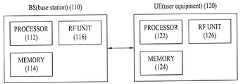
FIG. 43 illustrates a base station and a terminal that can be applied to the present invention.
이하의 기술은 CDMA(code division multiple access) , FDMA(frequency division multiple access), TDMA(time division multiple access), OFDMA(orthogonal frequency division multiple access), SC-FDMA(single carrier frequency division multiple access) 등과 같은 다양한 무선 접속 시스템에 사용될 수 있다. CDMA는 UTRA(Universal Terrestrial Radio Access)나 CDMA2000과 같은 무선 기술(radio technology)로 구현될 수 있다. TDMA는 GSM(Global System for Mobile communications)/GPRS(General Packet Radio Service)/EDGE(Enhanced Data Rates for GSM Evolution)와 같은 무선 기술로 구현될 수 있다. OFDMA는 IEEE 802.11 (Wi-Fi), IEEE 802.16 (WiMAX), IEEE 802-20, E-UTRA(Evolved UTRA) 등과 같은 무선 기술로 구현될 수 있다. UTRA는 UMTS(Universal Mobile Telecommunications System)의 일부이다. 3GPP(3rd Generation Partnership Project) LTE(long term evolution)은 E-UTRA를 사용하는 E-UMTS(Evolved UMTS)의 일부이고 LTE-A(Advanced)는 3GPP LTE의 진화된 버전이다. 설명을 명확하게 하기 위해, 3GPP LTE/LTE-A를 위주로 기술하지만 본 발명의 기술적 사상이 이에 제한되는 것은 아니다.The following description is to be understood as illustrative and non-limiting, such as code division multiple access (CDMA), frequency division multiple access (FDMA), time division multiple access (TDMA), orthogonal frequency division multiple access (OFDMA), single carrier frequency division multiple access And can be used in various wireless access systems. CDMA may be implemented in radio technology such as Universal Terrestrial Radio Access (UTRA) or CDMA2000. The TDMA may be implemented in a wireless technology such as Global System for Mobile communications (GSM) / General Packet Radio Service (GPRS) / Enhanced Data Rates for GSM Evolution (EDGE). OFDMA may be implemented in wireless technologies such as IEEE 802.11 (Wi-Fi), IEEE 802.16 (WiMAX), IEEE 802-20, and Evolved UTRA (E-UTRA). UTRA is part of the Universal Mobile Telecommunications System (UMTS). 3rd Generation Partnership Project (3GPP) Long term evolution (LTE) is part of E-UMTS (Evolved UMTS) using E-UTRA and LTE-A (Advanced) is an evolved version of 3GPP LTE. For clarity of description, 3GPP LTE / LTE-A is mainly described, but the technical idea of the present invention is not limited thereto.
무선 통신 시스템에서 단말은 기지국으로부터 하향링크(Downlink: DL)를 통해 정보를 수신하고, 단말은 기지국으로 상향링크(Uplink: UL)를 통해 정보를 전송한다. 기지국과 단말이 송수신하는 정보는 데이터 및 다양한 제어 정보를 포함하고, 이들이 송수신 하는 정보의 종류/용도에 따라 다양한 물리 채널이 존재한다.In a wireless communication system, a terminal receives information from a base station through a downlink (DL), and the terminal transmits information through an uplink (UL) to a base station. The information transmitted and received by the base station and the terminal includes data and various control information, and various physical channels exist depending on the type / use of the information transmitted / received.
도 1은 3GPP LTE 시스템에 이용되는 물리 채널들 및 이들을 이용한 일반적인 신호 전송 방법을 설명하기 위한 도면이다.1 is a view for explaining a physical channel used in a 3GPP LTE system and a general signal transmission method using the same.
전원이 꺼진 상태에서 다시 전원이 켜지거나, 새로이 셀에 진입한 단말은 단계 S101에서 기지국과 동기를 맞추는 등의 초기 셀 탐색(Initial cell search) 작업을 수행한다. 이를 위해 단말은 기지국으로부터 주동기 채널(Primary Synchronization Channel: P-SCH) 및 부동기 채널(Secondary Synchronization Channel: S-SCH)을 수신하여 기지국과 동기를 맞추고, 셀 ID 등의 정보를 획득한다. 그 후, 단말은 기지국으로부터 물리방송채널(Physical Broadcast Channel)를 수신하여 셀 내 방송 정보를 획득할 수 있다. 한편, 단말은 초기 셀 탐색 단계에서 하향링크 참조 신호(Downlink Reference Signal: DL RS)를 수신하여 하향링크 채널 상태를 확인할 수 있다.The terminal that is powered on again or the cell that has entered a new cell performs an initial cell search operation such as synchronizing with the base station in step S101. To this end, a mobile station receives a primary synchronization channel (P-SCH) and a secondary synchronization channel (S-SCH) from a base station, synchronizes with the base station, and acquires information such as a cell ID. Then, the terminal can receive the physical broadcast channel from the base station and acquire the in-cell broadcast information. Meanwhile, the UE can receive the downlink reference signal (DL RS) in the initial cell search step and check the downlink channel state.
초기 셀 탐색을 마친 단말은 단계 S102에서 물리 하향링크제어채널(Physical Downlink Control Channel: PDCCH) 및 물리하향링크제어채널 정보에 따른 물리하향링크공유 채널(Physical Downlink Control Channel: PDSCH)을 수신하여 좀더 구체적인 시스템 정보를 획득할 수 있다.Upon completion of the initial cell search, the UE receives a physical downlink control channel (PDCCH) and a physical downlink control channel (PDSCH) according to physical downlink control channel information in step S102, System information can be obtained.
이후, 단말은 기지국에 접속을 완료하기 위해 이후 단계 S103 내지 단계 S106과 같은 임의 접속 과정(Random Access Procedure)을 수행할 수 있다. 이를 위해 단말은 물리임의접속채널(Physical Random Access Channel: PRACH)을 통해 프리앰블(preamble)을 전송하고(S103), 물리하향링크제어채널 및 이에 대응하는 물리하향링크공유 채널을 통해 프리앰블에 대한 응답 메시지를 수신할 수 있다(S104). 경쟁 기반 임의 접속의 경우 추가적인 물리임의접속채널의 전송(S105) 및 물리하향링크제어채널 및 이에 대응하는 물리하향링크공유 채널 수신(S106)과 같은 충돌해결절차(Contention Resolution Procedure)를 수행할 수 있다.Thereafter, the terminal can perform a random access procedure such as steps S103 to S106 in order to complete the connection to the base station. To this end, the UE transmits a preamble through a Physical Random Access Channel (PRACH) (S103), and transmits a response message to the preamble through the physical downlink control channel and the corresponding physical downlink shared channel (S104). In the case of a contention-based random access, a contention resolution procedure such as transmission of an additional physical random access channel (S105) and physical downlink control channel and corresponding physical downlink shared channel reception (S106) can be performed .
상술한 바와 같은 절차를 수행한 단말은 이후 일반적인 상/하향링크 신호 전송 절차로서 물리하향링크제어채널/물리하향링크공유채널 수신(S107) 및 물리상향링크공유채널(Physical Uplink Shared Channel: PUSCH)/물리상향링크제어채널(Physical Uplink Control Channel: PUCCH) 전송(S108)을 수행할 수 있다. 단말이 기지국으로 전송하는 제어 정보를 통칭하여 상향링크 제어 정보(Uplink Control Information: UCI)라고 지칭한다. UCI는 HARQ ACK/NACK(Hybrid Automatic Repeat and reQuest Acknowledgement/Negative-ACK), SR(Scheduling Request), CQI(Channel Quality Indication), PMI(Precoding Matrix Indication), RI(Rank Indication) 등을 포함한다. UCI는 일반적으로 PUCCH를 통해 전송되지만, 제어 정보와 트래픽 데이터가 동시에 전송되어야 할 경우 PUSCH를 통해 전송될 수 있다. 또한, 네트워크의 요청/지시에 의해 PUSCH를 통해 UCI를 비주기적으로 전송할 수 있다.The UE having performed the procedure described above transmits a physical downlink control channel / physical downlink shared channel reception (S107) and a physical uplink shared channel (PUSCH) / physical downlink shared channel A physical uplink control channel (PUCCH) transmission (S108) may be performed. The control information transmitted from the UE to the BS is collectively referred to as Uplink Control Information (UCI). The UCI includes HARQ ACK / NACK (Hybrid Automatic Repeat and Random Acknowledgment / Negative-ACK), SR (Scheduling Request), CQI (Channel Quality Indication), PMI (Precoding Matrix Indication) and RI (Rank Indication). The UCI is generally transmitted through the PUCCH, but may be transmitted via the PUSCH when the control information and the traffic data are to be simultaneously transmitted. In addition, UCI can be transmitted non-periodically through the PUSCH according to the request / instruction of the network.
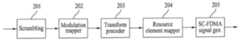
도 2는 단말이 상향링크 신호를 전송하기 위한 신호 처리 과정을 설명하기 위한 도면이다.FIG. 2 is a diagram for explaining a signal processing procedure for a UE to transmit an uplink signal.
상향링크 신호를 전송하기 위해 단말의 스크램블링(scrambling) 모듈(210)은 단말 특정 스크램블 신호를 이용하여 전송 신호를 스크램블 할 수 있다. 스크램블된 신호는 변조 맵퍼(220)에 입력되어 전송 신호의 종류 및/또는 채널 상태에 따라 BPSK(Binary Phase Shift Keying), QPSK(Quadrature Phase Shift Keying) 또는 16QAM/64QAM(Quadrature Amplitude Modulation) 방식을 이용하여 복소 심볼(complex symbol)로 변조된다. 변조된 복소 심볼은 변환 프리코더(230)에 의해 처리된 후, 자원 요소 맵퍼(240)에 입력되며, 자원 요소 맵퍼(240)는 복소 심볼을 시간-주파수 자원 요소에 맵핑할 수 있다. 이와 같이 처리된 신호는 SC-FDMA 신호 생성기(250)를 거쳐 안테나를 통해 기지국으로 전송될 수 있다.In order to transmit the uplink signal, the scrambling module 210 of the UE may scramble the transmission signal using the UE-specific scrambling signal. The scrambled signal is input to the modulation mapper 220, and is used to perform BPSK (Binary Phase Shift Keying), QPSK (Quadrature Phase Shift Keying), or 16QAM / 64QAM (Quadrature Amplitude Modulation) according to the type and / And is then modulated into a complex symbol. After the modulated complex symbols are processed by the transform precoder 230, they are input to the resource element mapper 240 and the resource element mapper 240 can map the complex symbols to the time-frequency resource elements. The signal thus processed can be transmitted to the base station via the antenna via the SC-FDMA signal generator 250. [
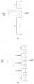
도 3은 기지국이 하향링크 신호를 전송하기 위한 신호 처리 과정을 설명하기 위한 도면이다.3 is a diagram for explaining a signal processing procedure for a base station to transmit a downlink signal.
3GPP LTE 시스템에서 기지국은 하향링크로 하나 이상의 코드워드(codeword)를 전송할 수 있다. 코드워드는 각각 도 2의 상향링크에서와 마찬가지로 스크램블 모듈(301) 및 변조 맵퍼(302)를 통해 복소 심볼로 처리될 수 있다, 그 후, 복소 심볼은 레이어 맵퍼(303)에 의해 복수의 레이어(Layer)에 맵핑되며, 각 레이어는 프리코딩 모듈(304)에 의해 프리코딩 행렬과 곱해져 각 전송 안테나에 할당될 수 있다. 이와 같이 처리된 각 안테나 별 전송 신호는 각각 자원 요소 맵퍼(305)에 의해 시간-주파수 자원 요소에 맵핑되며, 이후 OFDM(Orthogonal Frequency Division Multiple Access) 신호 생성기(306)를 거쳐 각 안테나를 통해 전송될 수 있다.In a 3GPP LTE system, a base station may transmit one or more codewords in the downlink. The codeword may be processed into a complex symbol through the
무선 통신 시스템에서 단말이 상향링크로 신호를 전송하는 경우에는 기지국이 하향링크로 신호를 전송하는 경우에 비해 PAPR(Peak-to-Average Ratio)이 문제된다. 따라서, 도 2 및 도 3과 관련하여 상술한 바와 같이 상향링크 신호 전송은 하향링크 신호 전송에 이용되는 OFDMA 방식과 달리 SC-FDMA(Single Carrier-Frequency Division Multiple Access) 방식이 이용되고 있다.In a wireless communication system, when a mobile station transmits a signal in an uplink, a peak-to-average ratio (PAPR) is more problematic than a case where a base station transmits a downlink signal. Therefore, unlike the OFDMA scheme used for downlink signal transmission, the uplink signal transmission uses a single carrier-frequency division multiple access (SC-FDMA) scheme as described above with reference to FIG. 2 and FIG.
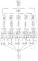
도 4는 SC-FDMA 방식과 OFDMA 방식을 설명하기 위한 도면이다. 3GPP 시스템은 하향링크에서 OFDMA를 채용하고 상향링크에서 SC-FDMA를 채용한다4 is a diagram for explaining an SC-FDMA scheme and an OFDMA scheme. The 3GPP system employs OFDMA in the downlink and SC-FDMA in the uplink
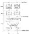
도 4를 참조하면, 상향링크 신호 전송을 위한 단말 및 하향링크 신호 전송을 위한 기지국 모두 직렬-병렬 변환기(Serial-to-Parallel Converter: 401), 부반송파 맵퍼(403), M-포인트 IDFT 모듈(404) 및 CP(Cyclic Prefix) 추가 모듈(406)을 포함하는 점에 있어서는 동일하다. 다만, SC-FDMA 방식으로 신호를 전송하기 위한 단말은 N-포인트 DFT 모듈(402)을 추가로 포함한다. N-포인트 DFT 모듈(402)은 M-포인트 IDFT 모듈(404)의 IDFT 처리 영향을 일정 부분 상쇄함으로써 전송 신호가 단일 반송파 특성(single carrier property)을 가지도록 한다.Referring to FIG. 4, a terminal for uplink signal transmission and a base station for downlink signal transmission includes a serial-to-
도 5는 주파수 도메인에서 단일 반송파 특성을 만족하기 위한 주파수 도메인상의 신호 맵핑 방식을 설명하는 도면이다. 도 5(a)는 로컬형 맵핑(localized mapping) 방식을 나타내며, 도 5(b)는 분산형 맵핑(distributed mapping) 방식을 나타낸다.5 is a diagram for explaining a signal mapping method in the frequency domain for satisfying a single carrier characteristic in the frequency domain. FIG. 5A shows a localized mapping method, and FIG. 5B shows a distributed mapping method.
SC-FDMA의 수정된 형태인 클러스터(clustered) SC-FDMA에 대해 설명한다. 클러스터(clustered) SC-FDMA는 부반송파 맵핑(mapping) 과정에서 DFT 프로세스 출력 샘플들을 부 그룹(sub-group)으로 나뉘고, 이들을 주파수 도메인(혹은 부반송파 도메인)에 불연속적으로 맵핑한다.A modified version of SC-FDMA, clustered SC-FDMA, is described. In a clustered SC-FDMA, the DFT process output samples are divided into sub-groups in a subcarrier mapping process and are discontinuously mapped to a frequency domain (or a subcarrier domain).
도 6은 클러스터 SC-FDMA에서 DFT 프로세스 출력 샘플들이 단일 캐리어에 맵핑되는 신호 처리 과정을 도시하는 도면이다. 도 7과 도 8은 클러스터 SC-FDMA에서 DFT 프로세스 출력 샘플들이 멀티캐리어(multi-carrier)에 맵핑되는 신호 처리 과정을 도시하는 도면이다. 도 6은 인트라 캐리어(intra-carrier) 클러스터 SC-FDMA를 적용하는 예이고, 도 7과 도 8은 인터 캐리어(inter-carrier) 클러스터 SC-FDMA를 적용하는 예에 해당한다. 도 7은 주파수 도메인에서 연속적(contiguous)으로 컴포넌트 캐리어(component carrier)가 할당된 상황에서 인접한 컴포넌트 캐리어간의 부반송파 간격(spacing)이 정렬된 경우 단일 IFFT 블록을 통해 신호를 생성하는 경우를 나타낸다. 도 8은 주파수 도메인에서 비연속적(non-contiguous)으로 컴포넌트 캐리어가 할당된 상황에서 복수의 IFFT 블록을 통해 신호를 생성하는 경우를 나타낸다.6 is a diagram illustrating a signal processing process in which DFT process output samples in a cluster SC-FDMA are mapped to a single carrier. 7 and 8 are diagrams illustrating a signal processing process in which DFT process output samples in a cluster SC-FDMA are mapped to multi-carriers. FIG. 6 shows an example of applying an intra-carrier cluster SC-FDMA, and FIGS. 7 and 8 correspond to an example of applying an inter-carrier cluster SC-FDMA. 7 shows a case where a signal is generated through a single IFFT block when subcarrier spacing between adjacent component carriers is aligned in a situation where a component carrier is allocated contiguously in the frequency domain. 8 shows a case where a signal is generated through a plurality of IFFT blocks in a situation where a component carrier is allocated non-contiguously in the frequency domain.
도 9는 세그먼트(segmented) SC-FDMA의 신호 처리 과정을 도시하는 도면이다.9 is a diagram showing a signal processing process of segmented SC-FDMA.
세그먼트 SC-FDMA는 임의 개수의 DFT와 같은 개수의 IFFT가 적용되면서 DFT와 IFFT간의 관계 구성이 일대일 관계를 가짐에 따라 단순히 기존 SC-FDMA의 DFT 확산과 IFFT의 주파수 부반송파 맵핑 구성을 확장한 것으로 NxSC-FDMA 또는 NxDFT-s-OFDMA라고 표현되기도 한다. 본 명세서는 이들을 포괄하여 세그먼트 SC-FDMA라고 명명한다. 도 9를 참조하면, 세그먼트 SC-FDMA는 단일 반송파 특성 조건을 완화하기 위하여 전체 시간 도메인 변조 심볼들을 N(N은 1보다 큰 정수)개의 그룹으로 묶어 그룹 단위로 DFT 프로세스를 수행한다.Segment SC-FDMA is an extension of DFT spreading of existing SC-FDMA and frequency subcarrier mapping of IFFT as the number of IFFTs is the same as that of any number of DFTs, as the relationship structure between DFT and IFFT has a one- -FDMA or NxDFT-s-OFDMA. The present specification encompasses them as a segment SC-FDMA. Referring to FIG. 9, in order to mitigate a single carrier characteristic condition, the segment SC-FDMA groups the entire time domain modulation symbols into N groups (N is an integer larger than 1) and performs a DFT process on a group basis.
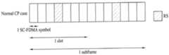
도 10은 상향링크 서브프레임의 구조를 예시한다.10 illustrates a structure of an uplink subframe.
도 10을 참조하면, 상향링크 서브프레임은 복수(예, 2개)의 슬롯을 포함한다. 슬롯은 CP(Cyclic Prefix) 길이에 따라 서로 다른 수의 SC-FDMA 심볼을 포함할 수 있다. 일 예로, 일반(normal) CP의 경우 슬롯은 7개의 SC-FDMA 심볼을 포함할 수 있다. 상향링크 서브프레임은 데이터 영역과 제어 영역으로 구분된다. 데이터 영역은 PUSCH를 포함하고 음성 등의 데이터 신호 전송하는데 사용된다. 제어 영역은 PUCCH를 포함하고 제어 정보를 전송하는데 사용된다. PUCCH는 주파수 축에서 데이터 영역의 양끝부분에 위치한 RB 쌍(RB pair)(예, m=0,1,2,3))(예, 주파수 반사(frequency mirrored)된 위치의 RB 쌍7)을 포함하며 슬롯을 경계로 호핑한다. 상향링크 제어 정보(즉, UCI)는 HARQ ACK/NACK, CQI(Channel Quality Information), PMI(Precoding Matrix Indicator), RI(Rank Indication) 등을 포함한다.Referring to FIG. 10, the uplink subframe includes a plurality of (e.g., two) slots. The slot may include a different number of SC-FDMA symbols according to a CP (Cyclic Prefix) length. For example, in the case of a normal CP, a slot may include 7 SC-FDMA symbols. The uplink subframe is divided into a data area and a control area. The data area includes a PUSCH and is used to transmit data signals such as voice. The control domain includes the PUCCH and is used to transmit control information. PUCCH includes an RB pair (e.g., m = 0, 1, 2, 3) (e.g.,
도 11은 상향링크로 참조신호를 전송하기 위한 신호 처리 과정을 설명하기 위한 도면이다. 데이터는 DFT 프리코더(precoder)를 통해 주파수 영역 신호로 변환된 뒤, 주파수 맵핑 후 IFFT를 통해 전송되는 반면, RS는 DFT 프리코더를 통하는 과정이 생략된다. 구체적으로, 주파수 영역에서 RS 시퀀스가 바로 생성(S11)된 후에, 로컬화 맵핑(S12), IFFT(S13) 과정 및 순환 전치(Cyclic Prefix; CP) 부착 과정(S14)을 순차적으로 거쳐 RS가 전송된다.11 is a diagram for explaining a signal processing procedure for transmitting a reference signal in an uplink. The data is converted into a frequency domain signal through a DFT precoder and then transmitted through an IFFT after frequency mapping, whereas the process of passing through a DFT precoder is omitted from the RS. Specifically, after the RS sequence is directly generated (S11) in the frequency domain, the RS is sequentially transmitted through the localization mapping (S12), the IFFT (S13) process and the cyclic prefix (CP) do.
RS 시퀀스


여기에서,


기본 시퀀스인


해당 그룹 내에서 시퀀스 그룹 번호


여기에서, q번째 루트 자도프-츄(Zadoff-Chu) 시퀀스는 다음의 수학식 3에 의해 정의될 수 있다.Here, the q-th root Zadoff-Chu sequence can be defined by the following equation (3).

여기에서, q는 다음의 수학식 4을 만족한다.Here, q satisfies the following expression (4).

여기에서, 자도프-츄 시퀀스의 길이


여기에서,


한편, RS 호핑(hopping)에 대해 설명하면 다음과 같다.RS hopping will be described as follows.
그룹 호핑 패턴


여기에서, mod는 모듈로(modulo)연산을 나타낸다.Here, mod represents a modulo operation.
17개의 서로 다른 호핑 패턴과 30개의 서로 다른 시퀀스 시프트 패턴이 존재한다. 상위 계층에 의해 제공된 그룹 호핑을 활성화시키는 파라미터에 의해 시퀀스 그룹 호핑이 가능(enabled)하거나 불가능할(disabled) 수 있다.There are 17 different hopping patterns and 30 different sequence shift patterns. Sequence group hopping may be enabled or disabled by a parameter that activates the group hopping provided by the upper layer.
PUCCH와 PUSCH는 동일한 호핑 패턴을 가지지만 서로 다른 시퀀스 시프트 패턴을 가질 수 있다.PUCCH and PUSCH have the same hopping pattern but can have different sequence shift patterns.
그룹 호핑 패턴

여기에서

시퀀스 시프트 패턴
PUCCH에 대해서, 시퀀스 시프트 패턴


이하, 시퀀스 호핑에 대해 설명한다.Sequence hopping will be described below.
시퀀스 호핑은 길이가
길이가


길이가


여기에서,

PUSCH에 대한 기준 신호는 다음과 같이 결정된다.The reference signal for PUSCH is determined as follows.
PUSCH에 대한 기준 신호 시퀀스


한 슬롯에서 순환 시프트는


표 3은 DCI(Downlink Control Information) 포맷 0에서 순환 시프트 필드와

PUSCH에서 상향링크 RS를 위한 물리적 맵핑 방법은 다음과 같다.A physical mapping method for the uplink RS in the PUSCH is as follows.
시퀀스는 진폭 스케일링 요소(amplitude scaling factor)

표준 순환 전치에 대해서는


정리하면, 길이가

도 12a는 표준 순환 전치(normal CP)의 경우에 PUSCH를 위한 DMRS(demodulation reference signal) 구조를 도시한 도면이고, 도 12b는 확장 순환 전치(extended CP)의 경우에 PUSCH를 위한 DMRS 구조를 도시한 도면이다. 도 12a에서는 4번째와 11번째 SC-FDMA 심볼을 통해 DMRS가 전송되며, 도 12b에서는 3번째와 9번째 SC-FDMA 심볼을 통해 DMRS가 전송된다.FIG. 12A shows a DMRS (demodulation reference signal) structure for a PUSCH in the case of a standard cyclic prefix (normal CP), and FIG. 12B shows a DMRS structure for a PUSCH in the case of an extended CP FIG. In FIG. 12A, the DMRS is transmitted through the fourth and eleventh SC-FDMA symbols, and in FIG. 12B, the DMRS is transmitted through the third and ninth SC-FDMA symbols.
도 13∼16은 PUCCH 포맷의 슬롯 레벨 구조를 예시한다. PUCCH는 제어 정보를 전송하기 위하여 다음의 형식을 포함한다.Figures 13-16 illustrate a slot level structure of the PUCCH format. The PUCCH includes the following format for transmitting the control information.
(1) 포맷(Format) 1: 온-오프 키잉(On-Off keying)(OOK) 변조, 스케줄링 요청(Scheduling Request: SR)에 사용(1) Format 1: On-off keying (OOK) modulation, used for Scheduling Request (SR)
(2) 포맷 1a와 포맷 1b: ACK/NACK(Acknowledgment/Negative Acknowledgment) 전송에 사용(2)
1) 포맷 1a: 1개의 코드워드에 대한 BPSK ACK/NACK1)
2) 포맷 1b: 2개의 코드워드에 대한 QPSK ACK/NACK[2)
(3) 포맷 2: QPSK 변조, CQI 전송에 사용(3) Format 2: Used for QPSK modulation and CQI transmission
(4) 포맷 2a와 포맷 2b: CQI와 ACK/NACK 동시 전송에 사용(4)
표 4는 PUCCH 포맷에 따른 변조 방식과 서브프레임 당 비트 수를 나타낸다. 표 5는 PUCCH 포맷에 따른 슬롯 당 RS의 개수를 나타낸다. 표 6은 PUCCH 포맷에 따른 RS의 SC-FDMA 심볼 위치를 나타낸 표이다. 표 4에서 PUCCH 포맷 2a와 2b는 표준 순환 전치의 경우에 해당한다.Table 4 shows the modulation scheme according to the PUCCH format and the number of bits per subframe. Table 5 shows the number of RSs per slot according to the PUCCH format. Table 6 shows SC-FDMA symbol positions of RS according to the PUCCH format. In Table 4, PUCCH formats 2a and 2b correspond to the case of standard cyclic transposition.


도 13은 표준 순환 전치인 경우의 PUCCH 포맷 1a와 1b를 나타낸다. 도 14는 확장 순환 전치인 경우의 PUCCH 포맷 1a와 1b를 나타낸다. PUCCH 포맷 1a와 1b는 동일한 내용의 제어 정보가 서브프레임 내에서 슬롯 단위로 반복된다. 각 단말에서 ACK/NACK 신호는 CG-CAZAC(Computer-Generated Constant Amplitude Zero Auto Correlation) 시퀀스의 서로 다른 순환 쉬프트(cyclic shift: CS)(주파수 도메인 코드)와 직교 커버 코드(orthogonal cover or orthogonal cover code: OC or OCC)(시간 도메인 확산 코드)로 구성된 서로 다른 자원을 통해 전송된다. OC는 예를 들어 왈쉬(Walsh)/DFT 직교 코드를 포함한다. CS의 개수가 6개이고 OC의 개수가 3개이면, 단일 안테나를 기준으로 총 18개의 단말이 동일한 PRB(Physical Resource Block) 안에서 다중화 될 수 있다. 직교 시퀀스 w0,w1,w2,w3는 (FFT 변조 후에) 임의의 시간 도메인에서 또는 (FFT 변조 전에) 임의의 주파수 도메인에서 적용될 수 있다.13 shows PUCCH formats 1a and 1b in the case of standard cyclic permutation. Fig. 14 shows PUCCH formats 1a and 1b in the case of extended cyclic permutation. In the PUCCH formats 1a and 1b, control information having the same contents is repeated in a slot unit in a subframe. In each terminal, the ACK / NACK signal includes a different cyclic shift (CS) (frequency domain code) and an orthogonal cover or orthogonal cover code (CG-CAZAC) sequence of a Computer- Generated Constant Amplitude Zero Auto Correlation OC or OCC) (time domain spreading code). The OC includes, for example, a Walsh / DFT orthogonal code. If the number of CSs is 6 and the number of OCs is 3, a total of 18 terminals based on a single antenna can be multiplexed in the same physical resource block (PRB). The orthogonal sequences w0, w1, w2, w3 may be applied in any time domain (after FFT modulation) or in any frequency domain (before FFT modulation).
SR과 지속적 스케줄링(persistent scheduling)을 위해, CS, OC 및 PRB(Physical Resource Block)로 구성된 ACK/NACK 자원은 RRC(Radio Resource Control)를 통해 단말에게 주어질 수 있다. 동적 ACK/NACK과 비지속적 스케줄링(non-persistent scheduling)을 위해, ACK/NACK 자원은 PDSCH에 대응하는 PDCCH의 가장 작은(lowest) CCE 인덱스에 의해 묵시적으로(implicitly) 단말에게 주어질 수 있다.For SR and persistent scheduling, ACK / NACK resources composed of CS, OC, and PRB (Physical Resource Block) can be given to the UE through RRC (Radio Resource Control). For dynamic ACK / NACK and non-persistent scheduling, the ACK / NACK resources may be implicitly given to the UE by the lowest CCE index of the PDCCH corresponding to the PDSCH.
도 15는 표준 순환 전치인 경우의 PUCCH 포맷 2/2a/2b를 나타낸다. 도 16은 확장 순환 전치인 경우의 PUCCH 포맷 2/2a/2b를 나타낸다. 도 15 및 16을 참조하면, 표준 CP의 경우에 하나의 서브프레임은 RS 심볼 이외에 10개의 QPSK 데이터 심볼로 구성된다. 각각의 QPSK 심볼은 CS에 의해 주파수 도메인에서 확산된 뒤 해당 SC-FDMA 심볼로 맵핑된다. SC-FDMA 심볼 레벨 CS 호핑은 인터-셀 간섭을 랜덤화 하기 위하여 적용될 수 있다. RS는 순환 쉬프트를 이용하여 CDM에 의해 다중화될 수 있다. 예를 들어, 가용한 CS의 개수가 12 또는 6라고 가정하면, 동일한 PRB 내에 각각 12 또는 6개의 단말이 다중화될 수 있다. 요컨대, PUCCH 포맷 1/1a/1b와 2/2a/2b 내에서 복수의 단말은 CS+OC+PRB와 CS+PRB에 의해 각각 다중화될 수 있다.15 shows the
PUCCH 포맷 1/1a/1b를 위한 길이-4와 길이-3의 직교 시퀀스(OC)는 다음의 표 7과 표 8에 나타난 바와 같다.The orthogonal sequence (OC) of length -4 and length -3 for the


PUCCH 포맷 1/1a/1b에서 RS를 위한 직교 시퀀스(OC)는 다음의 표 9와 같다.The orthogonal sequence (OC) for RS in

도 17은 PUCCH 포맷 1a와 1b에 대한 ACK/NACK 채널화(channelization)를 설명하는 도면이다. 도 17은
도 18은 동일한 PRB 내에서 PUCCH 포맷 1/1a/1b와 포맷 2/2a/2b의 혼합된 구조에 대한 채널화를 도시한 도면이다.18 is a diagram illustrating channelization for a mixed structure of
순환 쉬프트(Cyclic Shift: CS) 호핑(hopping)과 직교 커버(Orthogonal Cover: OC) 재맵핑(remapping)은 다음과 같이 적용될 수 있다.The cyclic shift (CS) hopping and the orthogonal cover (OC) remapping may be applied as follows.
(1) 인터-셀 간섭(inter-cell interference)의 랜덤화를 위한 심볼 기반 셀 특정 CS 호핑(1) symbol-based cell specific CS hopping for randomization of inter-cell interference
(2) 슬롯 레벨 CS/OC 재맵핑(2) Slot level CS / OC remapping
1) 인터-셀 간섭 램덤화를 위해1) for inter-cell interference ramdling
2) ACK/NACK 채널과 자원(k)사이의 맵핑을 위한 슬롯 기반 접근2) Slot-based approach for mapping between ACK / NACK channel and resource (k)
한편, PUCCH 포맷 1/1a/1b를 위한 자원(nr)은 다음의 조합을 포함한다.On the other hand, the resource (nr ) for the
(1) CS(=심볼 수준에서 DFT 직교 코드와 동일)(ncs)(1) CS (= equal to DFT orthogonal code at symbol level) (ncs )
(2) OC(슬롯 레벨에서 직교 커버)(noc)(2) OC (orthogonal cover at the slot level) (noc )
(3) 주파수 RB(Resource Block)(nrb)(3) Frequency RB (Resource Block) (nrb )
CS, OC, RB를 나타내는 인덱스를 각각, ncs, noc, nrb라 할 때, 대표 인덱스(representative index) nr은 ncs, noc, nrb를 포함한다. nr은 nr=(ncs, noc, nrb)를 만족한다.CS, OC, when the index indicating the RB larespectively, n cs, n oc, n rb, the representative index (representative index)r n includesn cs, n oc, n rb . nr satisfies nr = (ncs , noc , nrb ).
CQI, PMI, RI 및, CQI와 ACK/NACK의 조합은 PUCCH 포맷 2/2a/2b를 통해 전달될 수 있다. 리드 뮬러(Reed Muller: RM) 채널 코딩이 적용될 수 있다.CQI, PMI, RI, and a combination of CQI and ACK / NACK may be delivered via
예를 들어, LTE 시스템에서 UL CQI를 위한 채널 코딩은 다음과 같이 기술된다. 비트 스트림(bit stream)


채널 코딩 비트

여기에서, i = 0, 1, 2, …, B-1를 만족한다.Here, i = 0, 1, 2, ... , B-1.
표 11은 광대역 보고(단일 안테나 포트, 전송 다이버시티(transmit diversity) 또는 오픈 루프 공간 다중화(open loop spatial multiplexing) PDSCH) CQI 피드백을 위한 UCI(Uplink Control Information) 필드를 나타낸다.Table 11 shows Uplink Control Information (UCI) fields for CQI feedback for broadband reporting (single antenna port, transmit diversity or open loop spatial multiplexing PDSCH).

표 12는 광대역에 대한 CQI와 PMI 피드백을 위한 UCI 필드를 나타내며, 상기 필드는 폐 루프 공간 다중화(closed loop spatial multiplexing) PDSCH 전송을 보고한다.Table 12 shows UCI fields for CQI and PMI feedback for the wideband, which report closed loop spatial multiplexing PDSCH transmissions.

표 13은 광대역 보고를 위한 RI 피드백을 위한 UCI 필드를 나타낸다.Table 13 shows UCI fields for RI feedback for broadband reporting.

도 19는 PRB 할당을 도시한 도면이다. 도 19에 도시된 바와 같이, PRB는 슬롯 ns에서 PUCCH 전송을 위해 사용될 수 있다.19 is a diagram showing PRB allocation. As shown in Figure 19, PRB may be used for the PUCCH transmission in slot ns.
멀티캐리어 시스템 또는 캐리어 병합(carrier aggregation) 시스템은 광대역 지원을 위해 목표 대역(bandwidth)보다 작은 대역을 가지는 복수의 캐리어를 집합하여 사용하는 시스템을 말한다. 목표 대역보다 작은 대역을 가지는 복수의 캐리어를 집합할 때, 집합되는 캐리어의 대역은 기존 시스템과의 호환(backward compatibility)을 위해 기존 시스템에서 사용하는 대역폭으로 제한될 수 있다.A multi-carrier system or a carrier aggregation system refers to a system in which a plurality of carriers having a bandwidth smaller than a target bandwidth are collected and used for broadband support. When a plurality of carriers having a band smaller than the target band are collected, the bandwidth of the collected carriers may be limited to the bandwidth used in the existing system for backward compatibility with the existing system.
예를 들어, 기존의 LTE 시스템은 1.4, 3, 5, 10, 15, 20MHz의 대역폭을 지원하며, LTE 시스템으로부터 개선된 LTE-A(LTE-Advanced) 시스템은 LTE에서 지원하는 대역폭들만을 이용하여 20MHz보다 큰 대역폭을 지원할 수 있다. 또는 기존 시스템에서 사용하는 대역폭과 상관없이 새로운 대역폭을 정의하여 캐리어 병합을 지원할 수 있다. 멀티캐리어는 캐리어 병합 및 대역폭 집합과 혼용되어 사용될 수 있는 명칭이다. 또한, 캐리어 병합은 인접한(contiguous) 캐리어 병합과 인접하지 않은(non-contiguous) 캐리어 병합을 모두 통칭한다For example, existing LTE systems support bandwidths of 1.4, 3, 5, 10, 15, and 20 MHz, and improved LTE-A (LTE-Advanced) systems from LTE systems use only the bandwidths supported by LTE It can support bandwidths greater than 20MHz. Or it can support carrier merging by defining new bandwidth regardless of the bandwidth used by the existing system. Multicarriers are names that can be used interchangeably with carrier merging and bandwidth aggregation. In addition, carrier merging refers to both contiguous carrier merging and non-contiguous carrier merging
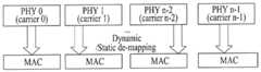
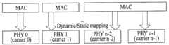
도 20은 기지국에서 하향링크 콤포넌트 캐리어들을 관리하는 개념을 예시하는 도면이며, 도 21은 단말에서 상향링크 콤포넌트 캐리어들을 관리하는 개념을 예시하는 도면이다. 설명의 편의를 위하여 이하에서는 도 20 및 도 21에서 상위 계층들을 MAC으로 간략화하여 설명한다.20 is a diagram illustrating a concept of managing downlink component carriers in a base station, and FIG. 21 is a diagram illustrating a concept of managing uplink component carriers in a terminal. For convenience of description, upper layers in FIGS. 20 and 21 will be briefly described as a MAC.
도 22는 기지국에서 하나의 MAC이 멀티캐리어를 관리하는 개념을 설명한다. 도 23은 단말에서 하나의 MAC이 멀티캐리어를 관리하는 개념을 설명한다.22 illustrates a concept that one MAC manages a multicarrier at a base station. FIG. 23 illustrates a concept that one MAC manages a multicarrier in a terminal.
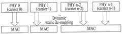
도 22 및 23을 참조하면, 하나의 MAC이 하나 이상의 주파수 캐리어를 관리 및 운영하여 송수신을 수행한다. 하나의 MAC에서 관리되는 주파수 캐리어들은 서로 인접(contiguous)할 필요가 없기 때문에 자원의 관리 측면에서 보다 유연(flexible) 하다는 장점이 있다. 도 22과 23에서 하나의 PHY는 편의상 하나의 컴포넌트 캐리어를 의미하는 것으로 한다. 여기서, 하나의 PHY는 반드시 독립적인 RF(Radio Frequency) 디바이스를 의미하는 것은 아니다. 일반적으로 하나의 독립적인 RF 디바이스는 하나의 PHY를 의미하나, 반드시 이에 국한되는 것은 아니며, 하나의 RF 디바이스는 여러 개의 PHY를 포함할 수 있다.Referring to FIGS. 22 and 23, one MAC manages and operates one or more frequency carriers to perform transmission and reception. The frequency carriers managed in one MAC have the advantage of being more flexible in terms of resource management since they do not need to be contiguous with each other. In FIGS. 22 and 23, one PHY is referred to as a component carrier for the sake of convenience. Here, one PHY does not necessarily mean an independent RF (Radio Frequency) device. In general, an independent RF device refers to a single PHY, but is not necessarily limited thereto, and one RF device may include multiple PHYs.
도 24는 기지국에서 복수의 MAC이 멀티 캐리어를 관리하는 개념을 설명한다. 도 25는 단말에서 복수의 MAC이 멀티캐리어를 관리하는 개념을 설명한다. 도 26은 기지국에서 복수의 MAC이 멀티 캐리어를 관리하는 다른 개념을 설명한다. 도 27은 단말에서 복수의 MAC이 멀티캐리어를 관리하는 다른 개념을 설명한다.24 illustrates a concept that a plurality of MACs manage multicarriers at a base station. FIG. 25 illustrates a concept that a plurality of MACs manage a multicarrier in a terminal. FIG. 26 illustrates another concept in which a plurality of MACs manage a multicarrier at a base station. FIG. 27 illustrates another concept in which a plurality of MACs manage a multicarrier at a terminal.
도 22 및 도 23과 같은 구조 이외에 도 24 내지 도 27과 같이 여러 개의 캐리어를 하나의 MAC이 아닌 여러 개의 MAC이 제어할 수도 있다.In addition to the structures shown in FIGS. 22 and 23, as shown in FIG. 24 to FIG. 27, a plurality of MACs may control not only one MAC but also a plurality of carriers.
도 24 및 도 25와 같이 각각의 캐리어를 각각의 MAC이 1:1로 제어할 수도 있고, 도 26 및 도 27과 같이 일부 캐리어에 대해서는 각각의 캐리어를 각각의 MAC이 1:1로 제어하고 나머지 1개 이상의 캐리어를 하나의 MAC이 제어할 수 있다.As shown in Figs. 24 and 25, each MAC may be controlled to be 1: 1 for each carrier, and for some carriers, each carrier may be controlled by 1: 1 for each MAC, One or more carriers can be controlled by one MAC.
상기의 시스템은 1개부터 N개까지의 다수의 캐리어를 포함하는 시스템이며 각 캐리어는 인접하거나 또는 인접하지 않게(non-contiguous) 사용될 수 있다. 이는 상향/하향링크에 구분 없이 적용될 수 있다. TDD 시스템은 각각의 캐리어 안에 하향링크와 상향링크의 전송을 포함하는 N개의 다수 캐리어를 운영하도록 구성되며, FDD 시스템은 다수의 캐리어를 상항링크와 하향링크에 각각 사용하도록 구성된다. FDD 시스템의 경우, 상향링크와 하향링크에서 병합되는 캐리어의 수 및/또는 캐리어의 대역폭이 다른 비대칭적 캐리어 병합도 지원할 수 있다.The system is a system that includes a number of carriers from one to N, and each carrier may be used contiguous or non-contiguous. This can be applied to uplink / downlink without any distinction. The TDD system is configured to operate N number of carriers including transmission of the downlink and uplink in each carrier, and the FDD system is configured to use a plurality of carriers on the uplink and the downlink, respectively. In case of the FDD system, asymmetric carrier merging in which the number of carriers merged in the uplink and the downlink and / or the bandwidth of the carrier is different may be supported.
상향링크와 하향링크에서 집합된 컴포넌트 캐리어의 개수가 동일할 때, 모든 컴포넌트 캐리어를 기존 시스템과 호환되도록 구성하는 것이 가능하다. 하지만, 호환성을 고려하지 않는 컴포넌트 캐리어가 본 발명에서 제외되는 것은 아니다.When the number of component carriers collected in the uplink and the downlink is the same, it is possible to configure all the component carriers to be compatible with the existing system. However, component carriers not considering compatibility are not excluded from the present invention.
이하에서는 설명의 편의를 위하여 PDCCH가 하향링크 컴퍼넌트 캐리어 #0으로 전송되었을 때, 해당 PDSCH는 하향링크 컴퍼넌트 캐리어 #0으로 전송되는 것을 가정하여 설명하지만, 교차-캐리어 스케쥴링(cross-carrier scheduling)이 적용되어 해당 PDSCH가 다른 하향링크 컴퍼넌트 캐리어를 통해 전송될 수 있음은 자명하다. 용어 "컴포넌트 캐리어" 는 등가의 다른 용어(예, 셀)로 대체될 수 있다.Hereinafter, for convenience of description, it is assumed that when the PDCCH is transmitted to the downlink
도 28은 캐리어 병합이 지원되는 무선 통신 시스템에서 상향링크 제어 정보(Uplink Control Information: UCI)가 전송되는 시나리오를 예시한다. 편의상, 본 예는 UCI가 ACK/NACK (A/N)인 경우를 가정한다. 그러나, 이는 설명의 편의를 위한 것으로서, UCI는 채널 상태 정보(예, CQI, PMI, RI), 스케줄링 요청 정보(예, SR)와 같은 제어 정보를 제한 없이 포함할 수 있다.FIG. 28 illustrates a scenario in which uplink control information (UCI) is transmitted in a wireless communication system in which carrier merging is supported. For convenience, this example assumes that the UCI is ACK / NACK (A / N). However, this is for convenience of description, and the UCI may include control information such as channel state information (e.g., CQI, PMI, RI), scheduling request information (e.g., SR)
도 28은 5개의 DL CC가 1개의 UL CC와 링크된 비대칭 캐리어 병합을 예시한다. 예시한 비대칭 캐리어 병합은 UCI 전송 관점에서 설정된 것일 수 있다. 즉, UCI를 위한 DL CC-UL CC 링키지와 데이터를 위한 DL CC-UL CC 링키지는 서로 다르게 설정될 수 있다. 편의상, 하나의 DL CC가 최대 두 개의 코드워드를 전송할 수 있다고 가정하면, UL ACK/NACK 비트도 적어도 2비트가 필요하다. 이 경우, 5개의 DL CC를 통해 수신한 데이터에 대한 ACK/NACK을 하나의 UL CC를 통해 전송하기 위해서는 적어도 10비트의 ACK/NACK 비트가 필요하다. 만약, DL CC 별로 DTX 상태도 지원하려면, ACK/NACK 전송을 위해 적어도 12비트 (=55=3125=11.61bits)가 필요하다. 기존의 PUCCH 포맷 1a/1b는 2비트까지 ACK/NACK을 보낼 수 있으므로, 이러한 구조는 늘어난 ACK/NACK 정보를 전송할 수 없다. 편의상, UCI 정보의 양이 늘어나는 원인으로 캐리어 병합을 예시하였지만, 이런 상황은 안테나 개수가 증가, TDD 시스템, 릴레이 시스템에서 백홀 서브프레임의 존재 등으로 발생할 수 있다. ACK/NACK과 유사하게, 복수의 DL CC와 연관된 제어 정보를 하나의 UL CC를 통해 전송하는 경우에도 전송되어야 하는 제어 정보의 양이 늘어난다. 예를 들어, 복수의 DL CC에 대한 CQICQI/PMI/RI를 전송해야 하는 경우 UCI 페이로드가 증가할 수 있다. DL CC 및 UL CC는 각각 DL Cell 및 UL Cell로도 지칭될 수 있다. 또한, 앵커 DL CC 및 앵커 UL CC는 각각 DL PCell(Primary Cell) 및 UL PCell로 지칭될 수 있다.FIG. 28 illustrates asymmetric carrier merging where five DL CCs are linked with one UL CC. The illustrated asymmetric carrier merging may be established in terms of UCI transmission. That is, the DL CC-UL CC linkage for UCI and the DL CC-UL CC linkage for data can be set differently. For convenience, assuming that one DL CC can transmit a maximum of two codewords, the UL ACK / NACK bit also requires at least two bits. In this case, at least 10 bits of ACK / NACK bits are required to transmit ACK / NACK for data received through five DL CCs through one UL CC. If the DTX state is also supported for each DL CC, at least 12 bits (= 55 = 3125 = 11.61 bits) are required for ACK / NACK transmission. Since the existing
DL 프라이머리 CC는 UL 프라이머리 CC와 링키지된 DL CC로 규정될 수 있다. 여기서 링키지는 묵시적(implicit), 명시적(explicit) 링키지(linkage)를 모두 포괄한다. LTE에서는 하나의 DL CC와 하나의 UL CC가 고유하게 페어링 되어 있다. 예를 들어, LTE 페어링에 의해, UL 프라이머리 CC와 링키지된 DL CC를 DL 프라이머리 CC라 명할 수 있다. 이것을 묵시적 링키지라 간주할 수 있다. 명시적 링키지는 네트워크가 사전에 미리 링키지를 구성(configuration)하는 것을 의미하며 RRC 등으로 시그널링 될 수 있다. 명시적 링키지에서, UL 프라이머리 CC와 페어링 되어 있는 DL CC를 프라이머리 DL CC라 명할 수 있다. 여기서, UL 프라이머리(또는 앵커) CC는 PUCCH가 전송되는 UL CC일 수 있다. 혹은 UL 프라이머리 CC는 PUCCH 혹은 PUSCH를 통해 UCI가 전송되는 UL CC일 수 있다. 또는 DL 프라이머리 CC는 상위 계층 시그널링을 통해 구성될 수 있다. 또는 DL 프라이머리 CC는 단말이 초기 접속을 수행한 DL CC일 수 있다. 또한, DL 프라이머리 CC를 제외한 DL CC는 DL 세컨더리 CC로 지칭될 수 있다. 유사하게, UL 프라이머리 CC를 제외한 UL CC는 UL 세컨더리 CC로 지칭될 수 있다.DL primary CC can be defined as UL primary CC and linked DL CC. Here, linkage covers both implicit and explicit linkage. In LTE, one DL CC and one UL CC are uniquely paired. For example, by LTE pairing, the UL primary CC and the linked DL CC can be called the DL primary CC. This can be considered an implicit linkage. Explicit linkage means that the network has previously configured the linkage in advance and can be signaled by RRC or the like. In an explicit linkage, the DL CC that is paired with the UL primary CC can be called the primary DL CC. Here, the UL primary (or anchor) CC may be the UL CC to which the PUCCH is transmitted. Alternatively, the UL primary CC may be the UL CC through which the UCI is transmitted via the PUCCH or PUSCH. Or the DL primary CC may be configured via higher layer signaling. Or the DL primary CC may be the DL CC from which the terminal initiated the initial connection. In addition, a DL CC other than a DL primary CC may be referred to as a DL secondary CC. Similarly, a UL CC other than an UL primary CC may be referred to as a UL secondary CC.
DL-UL 페어링은 FDD에만 해당될 수 있다. TDD는 동일한 주파수를 사용하므로 별도로 DL-UL 페어링이 정의되지 않을 수 있다. 또한, DL-UL 링키지는 SIB2의 UL EARFCN 정보를 통해 UL 링키지로부터 결정될 수 있다. 예를 들어, DL-UL 링키지는 초기 접속 시에 SIB2 디코딩을 통해 획득되고 그 이외에는 RRC 시그널링을 통해 획득될 수 있다. 따라서, SIB2 링키지만이 존재하고 다른 DL-UL 페어링은 명시적으로 정의되지 않을 수 있다. 예를 들어, 도 28의 5DL:1UL 구조에서, DL CC#0와 UL CC#0는 서로 SIB2 링키지 관계이며, 나머지 DL CC들은 해당 단말에게 설정되어 있지 않은 다른 UL CC들과 SIB2 링키지 관계에 있을 수 있다.DL-UL pairing can only be FDD-specific. Since TDD uses the same frequency, DL-UL pairing may not be defined separately. Also, the DL-UL linkage can be determined from the UL linkage through the UL EARFCN information of SIB2. For example, the DL-UL linkage may be obtained via SIB2 decoding at initial connection and otherwise obtained via RRC signaling. Therefore, only the SIB2 linkage exists and other DL-UL pairings may not be explicitly defined. For example, in the 5DL: 1 UL structure of FIG. 28, the
본 명세서 중에서 일부는 비대칭 캐리어 병합을 위주로 기재되어 있지만, 이는 설명을 위한 예시로서, 본 발명은 대칭 캐리어 병합을 포함한 다양한 캐리어 병합 시나리오에 대해 제한 없이 적용될 수 있다.Although some of the present specification describes mainly asymmetric carrier merging, this is an illustrative example and the present invention can be applied without limitation to various carrier merging scenarios including symmetric carrier merging.
실시예: SF 감소(spreading factor reduction)를 이용한 다중 UCI 전송Example: Multiple UCI transmission using spreading factor reduction
이하, 도면을 참조하여, 증대된 상향링크 제어 정보를 효율적으로 전송하기 위한 방안을 제안한다. 구체적으로, 증대된 상향링크 제어 정보를 전송하기 위한 새로운 PUCCH 포맷/신호처리 과정/자원 할당 방법 등을 제안한다. 설명을 위해, 본 발명에서 제안하는 PUCCH 포맷을 신규 PUCCH 포맷, LTE-A PUCCH 포맷, 또는 기존 LTE에 PUCCH 포맷 2까지 정의되어 있는 점에 비추어 PUCCH 포맷 3이라고 지칭한다.Hereinafter, a method for efficiently transmitting the increased uplink control information will be described with reference to the drawings. Specifically, a new PUCCH format / signal processing procedure / resource allocation method for transmitting uplink control information is proposed. For the sake of explanation, the PUCCH format proposed in the present invention is referred to as
본 발명에서 제안하는 PUCCH 포맷의 기술적 사상은 상향링크 제어 정보를 전송할 수 있는 임의의 물리 채널(예, PUSCH)에도 동일 또는 유사한 방식을 이용하여 용이하게 적용될 수 있다. 예를 들어, 본 발명의 실시예는 제어 정보를 주기적으로 전송하는 주기적 PUSCH 구조 또는 제어 정보를 비주기적으로 전송하는 비주기적 PUSCH 구조에 적용될 수 있다.The technical idea of the PUCCH format proposed in the present invention can be easily applied to any physical channel (e.g., PUSCH) capable of transmitting uplink control information using the same or similar method. For example, the embodiment of the present invention can be applied to a periodic PUSCH structure for periodically transmitting control information or an aperiodic PUSCH structure for periodically transmitting control information.
이하의 도면 및 실시예는 본 발명의 실시예에 따른 PUCCH 포맷에 적용되는 서브프레임/슬롯 레벨의 UCI/RS 심볼 구조로서 기존 LTE의 PUCCH 포맷 1(표준 CP)의 UCI/RS 심볼 구조를 이용하는 경우를 위주로 설명한다. 그러나, 도시된 PUCCH 포맷에서 서브프레임/슬롯 레벨의 UCI/RS 심볼 구조는 예시를 위해 편의상 정의된 것으로서 본 발명이 특정 구조로 제한되는 것은 아니다. 본 발명에 따른 PUCCH 포맷에서 UCI/RS 심볼의 개수, 위치 등은 시스템 설계에 맞춰 자유롭게 변형될 수 있다. 예를 들어, 본 발명의 실시예에 따른 PUCCH 포맷은 기존 LTE의 PUCCH 포맷 2/2a/2b의 구조를 이용하여 정의될 수 있다.The following figures and examples are illustrative of a UCI / RS symbol structure of a subframe / slot level applied to a PUCCH format according to an embodiment of the present invention, in which a UCI / RS symbol structure of a PUCCH format 1 (standard CP) . However, in the illustrated PUCCH format, the UCI / RS symbol structure of the subframe / slot level is defined for convenience of illustration, and the present invention is not limited to a specific structure. The number, position, etc. of UCI / RS symbols in the PUCCH format according to the present invention can be freely modified according to the system design. For example, the PUCCH format according to the embodiment of the present invention can be defined using the structure of the existing
본 발명의 실시예에 따른 PUCCH 포맷은 임의 종류/사이즈의 상향링크 제어 정보를 전송하는데 사용될 수 있다. 예를 들어, 본 발명의 실시예에 따른 PUCCH 포맷은 HARQ ACK/NACK, CQI, PMI, RI 등의 정보를 전송할 수 있고, 이들 정보는 임의 사이즈의 페이로드를 가질 수 있다. 설명의 편의상, 도면 및 실시예는 본 발명에 따른 PUCCH 포맷이 ACK/NACK 정보를 전송하는 경우를 위주로 설명한다.The PUCCH format according to the embodiment of the present invention can be used to transmit uplink control information of any kind / size. For example, the PUCCH format according to the embodiment of the present invention can transmit HARQ ACK / NACK, CQI, PMI, RI, and the like, and these information can have a payload of an arbitrary size. For convenience of explanation, the drawings and the embodiments mainly describe the case where the PUCCH format according to the present invention transmits ACK / NACK information.
도 29∼30은 서브프레임 내의 슬롯 0에 SF(Spreading Factor) 감소를 적용한 예를 도시한다. 도 29는 표준 CP인 경우이고 도 30은 확장 CP인 경우이다. 본 예는 기존 LTE의 PUCCH 포맷에 사용되던 OC의 SF 값을 4에서 2로 감소한 경우를 도시한다. 기본적인 신호 처리 과정은 도 13∼14를 참조하여 설명한 것과 동일하다.FIGS. 29 to 30 show an example in which SF (Spreading Factor) reduction is applied to
도 29∼30을 참조하면, 정보 비트(예, ACK/NACK)는 변조(예, QPSK, 8PSK, 16QAM, 64QAM 등)를 거쳐 변조 심볼로 변환된다(심볼 0,1). 이후, 변조 심볼은 기본 시퀀스(r0)와 곱해진 뒤, 순환 쉬프트, SF=2의 OC(Orthogonal Code)([w0 w1];[w2 w3]) 적용, IFFT 변환을 거쳐 SC-FDMA 심볼로 맵핑된다. 여기서, ro는 길이 12의 기본 시퀀스를 포함한다. OC는 LTE에 정의된 왈쉬 커버나 DFT 코드를 포함한다. 구현 방식에 따라, [w0 w1]과 [w2 w3]는 서로 독립적으로 주어지거나, 동일한 값을 갖도록 주어질 수 있다.29 to 30, information bits (e.g., ACK / NACK) are transformed into modulation symbols through modulation (e.g., QPSK, 8PSK, 16QAM, 64QAM, etc.) (
기존의 LTE PUCCH 포맷은 SF=4를 사용하므로 하나의 슬롯에서 하나의 변조 심볼만을 전송할 수 있고 동일한 정보가 슬롯 단위로 반복되므로, 결국 서브프레임 레벨에서 하나의 변조 심볼만을 전송할 수 있었다. 따라서, 기존 LTE의 PUCCH 포맷은 QPSK 변조 시 최대 2비트의 ACK/NACK 정보를 전송할 수 있었다. 그러나, 도 29 및 도 30에 예시된 PUCCH는 SF 감소로 인해 슬롯 당 2개의 변조 심볼을 전송할 수 있다. 또한, 각 슬롯이 서로 다른 정보를 전송하도록 할 경우, 서브프레임 레벨에서 최대 4개의 변조 심볼을 전송할 수 있다. 따라서, 도시된 PUCCH 포맷은 QPSK 변조 시 최대 8비트의 UCI(예, ACK/NACK)를 전송할 수 있다.Since the existing LTE PUCCH format uses SF = 4, only one modulation symbol can be transmitted in one slot, and the same information is repeated in units of slots. As a result, only one modulation symbol can be transmitted at a subframe level. Therefore, the conventional PUCCH format of LTE can transmit up to 2 bits of ACK / NACK information in QPSK modulation. However, the PUCCH illustrated in FIGS. 29 and 30 can transmit two modulation symbols per slot due to SF reduction. Also, when each slot is to transmit different information, up to four modulation symbols can be transmitted at the subframe level. Thus, the illustrated PUCCH format can transmit up to 8 bits of UCI (e.g., ACK / NACK) in QPSK modulation.
그러나, SF 감소는 (1) QPSK 변조 시 최대 8 비트까지만 전송할 수 있고, (2) 슬롯 기준으로 원래 4개의 SC-FDMA 심볼을 차지하던 UCI가 2개의 SC-FDMA 심볼만 차지하므로 UCI 당 에너지가 반으로 감소하여 3db의 SNR(Signal to Noise Ratio) 손실이 발생한다.However, SF reduction can be achieved by (1) transmitting up to a maximum of 8 bits in QPSK modulation, and (2) UCI occupying only two SC-FDMA symbols originally occupying four SC-FDMA symbols on a slot basis, The signal to noise ratio (SNR) loss of 3 dB occurs.
이하에서는 상기 문제를 해결하기 위한 방안에 대해 추가적으로 제안한다. 아래의 방안은 단독으로 사용되거나 서로 조합되어 사용될 수 있다.Hereinafter, a method for solving the above problem is further proposed. The following measures may be used alone or in combination with each other.
첫 번째 방안으로, UCI에 대해 조인트 코딩을 수행할 수 있다. 즉, 조인트 코딩을 통해 얻은 코딩 이득으로 성능 열화를 개선할 수 있다. 코딩 이득은 동일한 SNR을 유지하면서 더 많은 양의 UCI를 전송하거나, 동일한 양의 UCI를 더 높은 SNR로 전송하는데 사용될 수 있다.As a first approach, you can perform joint coding on UCI. That is, performance degradation can be improved by a coding gain obtained through joint coding. The coding gain can be used to transmit a larger amount of UCI while maintaining the same SNR, or to transmit the same amount of UCI to a higher SNR.
두 번째 방안으로, 채널 선택을 이용하여 문제를 해결할 수 있다. 채널 선택은 총 M개의 자원 중 N개만을 선택하여 전송함으로써,
도 31은 조인트 코딩과 SF 감소를 적용한 PUCCH 포맷 및 이를 위한 신호 처리 과정을 예시한다. 기본적인 처리 과정은 도 29 및 30을 참조하여 설명한 것과 동일하므로, 조인트 코딩을 위주로 설명한다.31 illustrates a PUCCH format applying joint coding and SF reduction and a signal processing process therefor. The basic processing procedure is the same as that described with reference to FIGS. 29 and 30, and therefore, the joint coding will be mainly described.
도 31을 참조하면, 채널 코딩 및 레이트 매칭 블록은 정보 비트 a_0, a_1, …, a_M-1(예, 다중 ACK/NACK 비트)를 채널 코딩하여 코딩 비트(encoded bit, coded bit or coding bit)(또는 코드워드) b_0, b_1, …, b_N-1을 생성한다. M은 정보 비트의 사이즈를 나타내고, N은 코딩 비트의 사이즈를 나타낸다. 정보 비트는 상향링크 제어 정보(UCI), 예를 들어 복수의 DL CC를 통해 수신한 복수의 데이터(또는 PDSCH)에 대한 다중 ACK/NACK을 포함한다. 여기서, 정보 비트 a_0, a_1, …, a_M-1는 정보 비트를 구성하는 UCI의 종류/개수/사이즈에 상관없이 조인트 코딩된다. 예를 들어, 정보 비트가 복수의 DL CC에 대한 다중 ACK/NACK을 포함하는 경우, 채널 코딩은 DL CC별, 개별 ACK/NACK 비트 별로 수행되지 않고, 전체 비트 정보를 대상으로 수행되며, 이로부터 단일 코드워드가 생성된다. 채널 코딩은 이로 제한되는 것은 아니지만 단순 반복(repetition), 단순 코딩(simplex coding), RM(Reed Muller) 코딩, 펑처링된 RM 코딩, RM-기반 코딩, TBCC(Tail-biting convolutional coding), LDPC(low-density parity-check) 혹은 터보-코딩을 포함한다. 코딩 비트는 변조 차수와 자원 양을 고려하여 레이트-매칭된다. 레이트-매칭은 순환 버퍼 레이트 매칭 또는 펑처링을 포함한다. 레이트 매칭 기능은 별도의 기능 블록을 통해 수행되거나, 생략될 수 있다.Referring to FIG. 31, the channel coding and rate matching block generates information bits a_0, a_1, ..., (or codewords) b_0, b_1, ..., a_M-1 (e.g., multiple ACK / NACK bits) , b_N-1. M denotes the size of the information bits, and N denotes the size of the coding bits. The information bits include multiple ACK / NACK for uplink control information (UCI), for example a plurality of data (or PDSCH) received via a plurality of DL CCs. Here, the information bits a_0, a_1, ... , a_M-1 are joint-coded regardless of the type / number / size of the UCI constituting the information bits. For example, when the information bits include multiple ACK / NACK for a plurality of DL CCs, channel coding is performed for each DL CC and not for individual ACK / NACK bits, but for all bit information, A single code word is generated. Channel coding may include, but is not limited to, simple repetition, simplex coding, Reed Muller coding, punctured RM coding, RM-based coding, tail-biting convolutional coding (TBCC) low-density parity-check or turbo-coding. The coding bits are rate-matched considering the modulation order and the amount of resources. Rate-matching includes cyclic buffer rate matching or puncturing. The rate matching function may be performed through a separate function block, or may be omitted.
변조기(modulator)는 코딩 비트 b_0, b_1, …, b_N-1을 변조하여 변조 심볼(symbol 0,1,2,3)을 생성한다. 변조 방법은 예를 들어, n-PSK(Phase Shift Keying), n-QAM(Quadrature Amplitude Modulation)을 포함한다(n은 2 이상의 정수). 구체적으로, 변조 방법은 BPSK(Binary PSK), QPSK(Quadrature PSK), 8-PSK, QAM, 16-QAM, 64-QAM 등을 포함할 수 있다.The modulator includes coding bits b_0, b_1, ..., , b_N-1 to generate modulation symbols (
도시하지는 않았지만, 분주기(divider)는 변조 심볼 0, 1, 2, 3을 각 슬롯으로 분주한다. 변조 심볼을 각 슬롯으로 분주하는 순서/패턴/방식은 특별히 제한되지 않는다. 예를 들어, 분주기는 변조 심볼을 앞에서부터 순서대로 각각의 슬롯에 분주할 수 있다. 이 경우, 도시한 바와 같이, 변조 심볼 0, 1은 슬롯 0에 분주되고, 변조 심볼 2, 3은 슬롯 1에 분주될 수 있다. 또한, 변조 심볼은 각각의 슬롯으로 분주 시에 인터리빙 (또는 퍼뮤테이션) 될 수 있다. 예를 들어, 짝수 번째 변조 심볼은 슬롯 0에 분주되고 홀수 번째 변조 심볼은 슬롯 1에 분주될 수 있다. 변조 과정과 분주 과정은 순서가 서로 바뀔 수 있다. 이후, 슬롯으로 분주된 변조 심볼은 기본 시퀀스(r0)와의 곱, 순환 쉬프트, SF=2의 OC(Orthogonal Code)([w0 w1];[w2 w3]) 적용, IFFT 변환을 거쳐 SC-FDMA 심볼로 맵핑된다.Although not shown, a divider divides
도시한 PUCCH 포맷은 SF를 감소시킴으로써 더 많은 수의 변조 심볼을 전송하는 것이 가능하다. SF 감소로 인해 줄어든 UCI 당 전송 에너지(또는 SNR)는 조인트 코딩을 수행함으로써 보상된다. 또한, 조인트 코딩으로 인한 코딩 이득은 SNR 열화 없이 QPSK보다 높은 변조 차수를 갖는 변조 기법을 사용하게 할 수 있다.The illustrated PUCCH format is capable of transmitting a larger number of modulation symbols by reducing the SF. The reduced transmission energy (or SNR) per UCI due to SF reduction is compensated by performing joint coding. In addition, the coding gain due to joint coding can make use of modulation schemes with modulation orders higher than QPSK without SNR degradation.
다음으로, 채널 선택을 이용하는 방안, 즉 다중 자원을 할당 받고 자원 선택 도메인을 UCI 정보로 사용하는 방안에 대해 구체적으로 설명한다. 이하, 설명의 용이함을 위해, 총 2개(M=2)의 자원 중에서 1개(N=1)의 자원을 선택하는 경우를 위주로 설명한다. 또한, 이하의 도면 및 설명에서, 채널 코딩 블록은 생략 가능하나, 설명의 편의를 위해 채널 코딩 블록이 존재하는 것을 가정한다.Next, a method of using channel selection, that is, a method of allocating multiple resources and using a resource selection domain as UCI information will be described in detail. Hereinafter, for ease of explanation, a case where one resource (N = 1) is selected from a total of two resources (M = 2) will be mainly described. In the following drawings and description, the channel coding block may be omitted, but it is assumed that a channel coding block exists for convenience of explanation.
채널 선택을 위한 다중 자원이 존재하는 PRB는 특별히 제한되지 않지만, 설명의 편의를 위해 동일한 PRB 내에 존재한다고 가정한다. 채널 선택을 위한 다중 자원은 물리 채널 시그널링(예, PDCCH), 또는 상위 계층(예, RRC, MAC, BCH) 시그널링을 통해 명시적으로 할당될 수 있다. 또한, 채널 선택을 위한 다중 자원은 기존 LTE의 동적 ACK/NACK 자원 할당과 같이 묵시적으로 할당될 수 있다.The PRB in which multiple resources for channel selection exist is not particularly limited, but is assumed to exist in the same PRB for convenience of explanation. Multiple resources for channel selection may be explicitly allocated via physical channel signaling (e.g., PDCCH) or higher layer (e.g., RRC, MAC, BCH) signaling. In addition, multiple resources for channel selection may be implicitly assigned, such as dynamic ACK / NACK resource allocation of existing LTE.
기존 LTE의 동적 ACK/NACK 자원 할당을 이용한 다중 자원 할당에 대해 보다 구체적으로 예시한다. 편의상, 채널 선택을 위해 두 개의 직교 자원(Orthogonal resource: OR)을 사용한다고 가정한다(M=2). 이 경우, 제1 직교 자원의 인덱스는 DL 그랜트 PDCCH의 가장 작은(lowest) CCE 인덱스와 상응하는 인덱스로 결정되고, 제2 직교 자원의 인덱스는 제1 직교 자원의 인덱스와 오프셋 값을 조합하여 얻을 수 있다. 오프셋 값은 특별히 제한되지 않으며, 예를 들어 1일 수 있다.The multiple resource allocation using the dynamic ACK / NACK resource allocation of the existing LTE will be described in more detail. For convenience, it is assumed that two orthogonal resources (OR) are used for channel selection (M = 2). In this case, the index of the first orthogonal resource is determined as an index corresponding to the lowest CCE index of the DL grant PDCCH, and the index of the second orthogonal resource is obtained by combining the index and the offset value of the first orthogonal resource. have. The offset value is not particularly limited, and may be 1, for example.
채널 선택을 위한 다중 자원이 순환 쉬프트 도메인으로 한정되는 경우, 제2 직교 자원의 인덱스는 전체 순환 쉬프트 개수(예, 12개)의 모듈로 형태로 표현 가능하다. 예를 들어, 제2 직교 자원의 순환 쉬프트 인덱스는 (nCS,OR1+오프셋)mod(12)=0일 수 있다. nCS,OR1은 제1 직교 자원의 순환 쉬프트 인덱스를 나타내고, mod는 모듈로 연산을 나타낸다. 이 경우, 채널 선택을 위한 다중 자원은 순환 쉬프트만이 서로 다르게 설정된다.When multiple resources for channel selection are limited to a cyclic shift domain, the index of the second orthogonal resource can be expressed in a modulo form of a total number of cyclic shifts (e.g., 12). For example, the cyclic shift index of the second orthogonal resource may be (nCS, OR 1 + offset) mod (12) = 0. nCS, OR1 denotes a cyclic shift index of the first orthogonal resource, and mod denotes a modulo operation. In this case, the multiple resources for channel selection are set differently from each other only in the cyclic shift.
다른 예로, 채널 선택을 위한 다중 자원이 순환 쉬프트와 직교 코드로 한정되는 경우(즉, 동일한 PRB 내의 자원으로 한정되는 경우), 한 PRB 내의 가용 자원의 개수가 18이라고 하면, 제2 직교 자원의 인덱스는 (nOR1+오프셋)mod(18)=0일 수 있다. nOR1은 PRB 내에서 제1 직교 자원의 인덱스를 나타낸다. 이 경우, 직교 자원의 인덱스는 순환 쉬프트와 직교 코드의 조합을 대표한다.As another example, if the number of available resources in one PRB is 18 when multiple resources for channel selection are limited to cyclic shifts and orthogonal codes (i.e., limited to resources in the same PRB), then the index of the second orthogonal resource (NOR1 + offset) mod (18) = 0. nOR1 represents the index of the first orthogonal resource in the PRB. In this case, the index of the orthogonal resource represents a combination of a cyclic shift and an orthogonal code.
도 32는 채널 선택과 SF 감소를 적용한 PUCCH 포맷 및 이를 위한 신호 처리 과정을 예시한다. 도 32에 도시된 채널 코딩 블록은 설명의 편의를 위한 것으로서 생략 가능하다. 채널 선택을 제외한 기본적인 신호 처리 과정은 도 30∼31을 참조하여 설명한 것과 동일하다.32 illustrates a PUCCH format applying channel selection and SF reduction and a signal processing process therefor. The channel coding block shown in FIG. 32 is omitted for convenience of explanation. The basic signal processing process except for channel selection is the same as that described with reference to Figs.
도 32를 참조하면, 변조기는 채널 선택을 고려하여 변조 맵핑을 수행할 수 있다. 예를 들어, 슬롯 0을 참조하면, 변조기는 코딩 비트로부터 4개의 변조 심볼(symbol 0,1,2,3)을 생성한다. 이 중, 변조 심볼 0,2는 제1 직교 자원에 대응하고, 변조 심볼 1,3은 제2 직교 자원에 대응한다. 제1 직교 자원과 제2 직교 자원은 순환 쉬프트와 직교 코드로 한정된다. 도면에서 동일한 번호의 순환 쉬프트(즉, 순환 쉬프트 M(예, M=0, 1))는 동일한 직교 자원으로부터 파생된 CS임을 의미할 뿐 이들이 동일한 값을 갖는다는 것을 의미하지는 않는다. 예를 들어, SC-FDMA 또는 슬롯 레벨에서 CS 호핑이 적용되면, 순환 쉬프트 M은 SC-FDMA 심볼 또는 슬롯에 따라 다른 값을 가질 수 있다. 도시된 직교 코드(wa,b)(예, [w0,1;w1,1],[w2,1;w3,1] 또는 [w0,1;w1,1;w2,1;w3,1])에서 a는 직교 코드 내에서의 원소 인덱스를 나타내고, b는 직교 코드 인덱스를 나타낸다.Referring to FIG. 32, the modulator can perform modulation mapping considering channel selection. For example, referring to
채널 선택에 따라, 변조기는 변조 심볼 0 또는 1 중에서 하나에만 실제 변조 값을 부여하고 나머지에는 0을 부여한다. 마찬가지로, 변조기는 변조 심볼 2 또 3 중에서 하나에만 실제 변조 값을 부여하고 나머지에는 0을 부여한다. 채널 선택은 변조 심볼마다 독립적으로 이뤄질 수 있으므로 SC-FDMA 심볼 0∼1에서는 제1 직교 자원이 선택되고, SC-FDMA 심볼 5∼6에서는 제2 직교 자원이 선택될 수 있다.Depending on the channel selection, the modulator assigns the actual modulation value to only one of the
도시하지는 않았지만, 상술한 채널 선택 과정은 자원 도메인 단에서 등가적으로 수행될 수 있다. 예를 들어, 변조기는 SC-FDMA 심볼 0∼1과 SC-FDMA 심볼 5∼6에 각각 대응되는 두 개의 변조 심볼(symbol 0,1)을 생성한다. 이후, 채널 선택 결과에 따라, 변조 심볼 0에는 제1 직교 자원 또는 제2 직교 자원 중 하나가 적용된다. 마찬가지로, 변조 심볼 1에도 제1 직교 자원 또는 제2 직교 자원 중 하나가 적용된다.Although not shown, the above-described channel selection process can be equivalently performed at the resource domain stage. For example, the modulator generates two modulation symbols (
자원 선택이 변조 단 또는 자원 도메인 단에서 이뤄지든 물리적인 결과는 동일하다. 설명의 용이함을 위해, 본 명세서에서 자원 선택은 변조기를 통해 이뤄지는 경우를 위주로 설명한다. 변조 차수는 따로 구속조건이 없지만, 특별히 QPSK 나 8PSK 변조를 수행할 수 있다.The physical results are the same whether the resource selection is made at the modulation stage or the resource domain stage. For ease of explanation, the resource selection in this specification mainly focuses on the case where it is performed through a modulator. The modulation order is not constrained, but QPSK or 8PSK modulation can be performed specially.
UCI가 다중 ACK/NACK인 경우를 가정하여 보다 구체적으로 예시한다. 다중 ACK/NACK은 복수의 DL CC로부터 수신한 데이터에 대한 ACK/NACK을 포함한다. 채널 코딩 블록은 다중 ACK/NACK을 조인트 코딩하여 단일 코드워드를 생성한다. 채널 코딩 방식은 예를 들어 RM-기반 코딩, TBCC, 혹은 터보 코딩을 포함한다. 이후, 코딩 비트(즉, 코드워드)는 레이트 매칭된다. 레이트-매칭 방식은 순환 버퍼 레이트 매칭을 포함한다. 또한, 레이트 매칭은 코드워드로부터 원하는 코딩 비트 사이즈만을 남기는 펑처링을 포함한다. 예를 들어, LTE PUCCH에 사용되는 RM 코딩(20,A)를 사용한다고 가정하자. M=2, N=1이고 4개의 QPSK 변조 심볼 사용할 경우, 12개의 코딩(encoded) 비트가 필요하다. 이 경우, LTE RM (20,A)로부터 길이 20의 코딩 비트를 생성한 후 뒤의 8비트를 펑처링 할 수 있다. RM이 (8,A)의 사이즈를 지원한다면 길이 8의 코딩 비트를 생성하고 길이 12가 되도록 순환 버퍼 레이트 매칭을 수행할 수 있다([a0,a1,…,a7,a0,a1,a2,a3] => 길이 12). M=2, N=1이고 4개의 8PSK 변조 심볼을 사용한다면 총 16개의 코딩 비트가 필요하다. 이 경우, LTE RM(20,A)를 이용해 정보 비트를 20비트로 코딩한 후 16비트로 펑처링 할 수 있다.Assuming that the UCI is multiple ACK / NACK, it will be more specifically illustrated. The multiple ACK / NACK includes ACK / NACK for data received from a plurality of DL CCs. The channel coding block joint-codes multiple ACK / NACKs to generate a single codeword. The channel coding scheme includes, for example, RM-based coding, TBCC, or turbo coding. The coding bits (i.e., codewords) are then rate matched. The rate-matching scheme includes cyclic buffer rate matching. Rate matching also includes puncturing that leaves only the desired coding bit size from the codeword. For example, assume that we use the RM coding (20, A) used in the LTE PUCCH. When M = 2, N = 1 and four QPSK modulation symbols are used, 12 encoded bits are required. In this case, it is possible to generate a coding bit of length 20 from the LTE RM 20 (A), and puncture the latter 8 bits. If RM supports the size of (8, A), it can generate a coding bit of
채널 코딩 후, 코딩 비트를 물리 채널에 맵핑되도록 변조한다. 본 예에서, 변조기는 QPSK 혹은 8PSK 변조를 수행하여 총 8개의 변조 심볼을 생성한다. 본 예와 같이, M=2, N=1인 경우 심볼 0과 심볼 1 중에서 하나만 실제 변조 심볼 값을 갖고 나머지 하나는 0이 될 수 있다. 심볼 2와 심볼 3의 경우도 마찬가지이다.After channel coding, the coding bit is modulated to be mapped to the physical channel. In this example, the modulator performs QPSK or 8PSK modulation to generate a total of eight modulation symbols. As shown in this example, when M = 2 and N = 1, only one of
설명의 용이함을 위해 둘 중에 하나가 0이 되는 것은 심볼 표현 방법에서 이미 포괄한다고 가정한다. 이후, 심볼 0과 1에는 2개의 직교 자원이 적용된다. 마찬가지로, 심볼 2와 3에도 2개의 직교 자원이 적용된다. 각각의 직교 자원은 OS0=(CS0,OC0), OS1=(CS1,OC1)로 구성되고 같은 PRB 내에서 존재한다고 가정하자.For ease of explanation, it is assumed that one of the two becomes 0 in the symbol representation method. Thereafter, two orthogonal resources are applied to
구체적으로, 채널 선택을 적용할 경우 UCI는 다음과 같이 전송된다.Specifically, when channel selection is applied, the UCI is transmitted as follows.
- OS0을 통해 변조 심볼 0을 슬롯 0의 SC-FDMA 심볼 0∼1을 통해 전송-
- OS1을 통해 변조 심볼 1을 슬롯 0의 SC-FDMA 심볼 0∼1을 통해 전송- Transmit
- OS0을 통해 변조 심볼 2를 슬롯 0의 SC-FDMA 심볼 5∼6을 통해 전송- Transmit
- OS1을 통해 변조 심볼 3을 슬롯 0의 SC-FDMA 심볼 5∼6을 통해 전송- Transmit
- OS0을 통해 변조 심볼 4를 슬롯 1의 SC-FDMA 심볼 0∼1을 통해 전송-
- OS1을 통해 변조 심볼 5을 슬롯 1의 SC-FDMA 심볼 0∼1을 통해 전송- Transmit
- OS0를 통해 변조 심볼 6를 슬롯 1의 SC-FDMA 심볼 5∼6을 통해 전송-
- OS1을 통해 변조 심볼 7을 슬롯 1의 SC-FDMA 심볼 5∼6을 통해 전송-
순환 쉬프트는 SC-FDMA 심볼 단위로 셀-특정하게 호핑될 수 있으며, OC도 변조 심볼 단위 혹은 슬롯 단위로 호핑 패턴을 정의할 수 있다. 상술한 전송 방법을 통해 LTE 대비 CM의 증가 없이 단일 반송파 특성을 만족시킬 수 있다.The cyclic shift can be cell-specific hopped on an SC-FDMA symbol basis, and OC can define a hopping pattern on a modulation symbol unit or slot basis. The single carrier characteristic can be satisfied without increasing the CM compared with the LTE through the above transmission method.
이하, QPSK 변조 시의 채널 선택 과정을 구체적으로 예시한다. 4개의 QPSK 변조 심볼이 2개의 자원 중 하나를 통해 전송한다고 가정하면, 채널 코딩 및 레이트 매칭을 거쳐 ACK/NACK 정보로부터 12개의 코딩 비트 b0,…,b11가 얻어진다. 3개의 코딩 비트가 하나의 [변조 심볼, 자원 선택] 조합에 상응하며, 코딩 비트 열은 s0,…,s7로 변조될 수 있다. 채널 선택에 따라, s0,…,s7 중에서 네 개는 실제 변조 값을 갖고, 남은 네 개는 0을 갖는다.Hereinafter, a channel selection process at the time of QPSK modulation will be specifically described. Assuming that four QPSK modulation symbols are transmitted through one of the two resources, 12 coding bits b0, ..., bk from the ACK / NACK information through channel coding and rate matching. , b11 are obtained. The three coding bits correspond to one [modulation symbol, resource selection] combination, the coding bit sequence is s0, ... , s7. Depending on the channel selection, s0, ... , four of s7 have the actual modulation value, and the remaining four have zero.
표 14는 QPSK 변조 시의 맵핑 규칙을 예시한다. 표 15는 코딩 비트 열이 <b0,…,b11>=<1,1,1, 0,1,0, 1,0,0, 0,0,1>인 경우에 표 14를 적용한 결과이다.Table 14 illustrates mapping rules in QPSK modulation. Table 15 shows the coding bit sequence < b0, ... , and b11> = <1,1,1,0,1,0,0,0,0,0,0,1>.

표에서, ICS1은 제1 직교 자원 인덱스를 나타내고, ICS2는 제2 직교 자원 인덱스를 나타낸다. 공백은 0을 나타낸다. I는 동상(in phase) 위상을 나타내고 Q는 직교 위상(quadrature phase)을 나타낸다.In the table, ICS1 represents a first orthogonal resource index, and ICS2 represents a second orthogonal resource index. Blank indicates 0. I represents an in phase phase and Q represents a quadrature phase.

표 14는 등가의 다른 형태로 변형될 수 있다. 예를 들어, 표 14의 맵핑 규칙은 LTE PUCCH 포맷에 사용되는 QPSK 맵핑 테이블을 이용하여 변형될 수 있다. 표 16은 LTE PUCCH 포맷 1a/1b에서 정의된 QPSK 맵핑 테이블을 나타내고, 표 17은 표 16의 QPSK 성상을 이용한 맵핑 규칙을 나타낸다.Table 14 can be modified to other equivalent forms. For example, the mapping rules of Table 14 may be modified using the QPSK mapping table used in the LTE PUCCH format. Table 16 shows the QPSK mapping table defined in the


표 18은 QPSK 변조 시의 다른 맵핑 규칙을 나타낸다. 표 18의 맵핑 규칙은 유클리디안 거리(Eucledian distance)를 고려하여 설계된 것이다. 도 33은 표 18의 맵핑에 따른 QPSK 성상을 나타낸다. 유클리디안 거리는 대각선 상에 위치한 심볼들간에 가장 크다. 유클리디안 거리가 클수록 상호간에 오류가 발생할 확률이 적다. 표 18 및 도 33의 맵핑 규칙은 해밍 거리(Hamming distance)가 가장 큰 비트를 대각선 상에 배치하는 식으로 구성되었다.Table 18 shows other mapping rules in QPSK modulation. The mapping rules in Table 18 are designed in consideration of the Eucledian distance. 33 shows the QPSK constellation according to the mapping in Table 18. FIG. The Euclidean distance is largest among the symbols located on the diagonal. The larger the Euclidean distance, the less likely that errors will occur. The mapping rules of Table 18 and FIG. 33 are constructed such that bits having the largest Hamming distance are arranged on a diagonal line.

표 19는 코딩 비트 열이 <b0,…,b11>=<1,1,1, 0,1,0, 1,0,0, 0,0,1>인 경우에 표 18을 적용한 결과를 나타낸다.Table 19 shows the coding bit sequence < b0, ... , and b11> = <1,1,1,0,1,0,0,0,0,0,0,1>.

다음으로, 8PSK 변조 시의 채널 선택 과정을 구체적으로 예시한다. 4개의 8PSK 변조 심볼을 2개의 자원 중 하나를 통해 전송한다고 가정하면, 채널 코딩 및 레이트 매칭을 거쳐 ACK/NACK 정보로부터 16개의 코딩 비트 b0,…,b15가 얻어진다. 4개의 코딩 비트가 하나의 [변조 심볼, 자원 선택] 조합에 상응하며, 코딩 비트 열은 s0,…,s7로 변조될 수 있다. 채널 선택에 따라, s0,…,s7 중에서 네 개는 실제 변조 값을 갖고, 남은 네 개는 0을 갖는다.Next, a channel selection process at the time of 8PSK modulation will be specifically illustrated. Assuming that four 8PSK modulation symbols are transmitted through one of the two resources, 16 coding bits b0, ..., bk from the ACK / NACK information are subjected to channel coding and rate matching. , b15 are obtained. The four coding bits correspond to one [modulation symbol, resource selection] combination, and the coding bit sequence corresponds to s0, ... , s7. Depending on the channel selection, s0, ... , four of s7 have the actual modulation value, and the remaining four have zero.
표 20은 8PSK 변조 시의 맵핑 규칙을 예시한다. 표 20의 맵핑 규칙은 유클리디안 거리를 고려하여 설계되었다. 도 34는 표 20의 맵핑에 따른 QPSK 성상을 나타낸다. 도 34를 참조하면, 최적의 유클리디안 거리를 확보하기 위해 변조 심볼들은 그레이 맵핑(gray mapping)에 기반하여 배치되었다. 8PSK 맵핑을 통해 더 나은 코딩 이득을 얻을 수 있다.Table 20 illustrates the mapping rules for 8PSK modulation. The mapping rules in Table 20 are designed with Euclidean distance taken into account. 34 shows the QPSK constellation according to the mapping shown in Table 20. FIG. Referring to FIG. 34, modulation symbols are arranged based on gray mapping to ensure an optimal Euclidean distance. Better coding gain can be obtained through 8PSK mapping.

표에서, ICS1은 제1 직교 자원 인덱스를 나타내고, ICS2는 제2 직교 자원 인덱스를 나타낸다. 공백은 0을 나타낸다. I는 동상(in phase) 위상을 나타내고 Q는 직교 위상(quadrature phase)을 나타낸다.In the table, ICS1 represents a first orthogonal resource index, and ICS2 represents a second orthogonal resource index. Blank indicates 0. I represents an in phase phase and Q represents a quadrature phase.
표 21은 코딩 비트 열이 <b0,…,b15>=<1,1,0,1, 1,0,0,0, 1,0,1,0, 1,0,1,1>인 경우에 표 20을 적용한 결과를 나타낸다.Table 21 shows the coding bit sequence < b0, ... , and b15> = <1,1,0,1,1,0,0,0,1,0,1,0,1,0,1,1>.

표 22는 8PSK 변조 시의 다른 맵핑 규칙을 예시한다. 표 23은 코딩 비트 열이 <b0,…,b15>=<1,1,0,1, 1,0,0,0, 1,0,1,0, 1,0,1,1>인 경우에 표 20을 적용한 결과를 나타낸다.Table 22 illustrates different mapping rules for 8PSK modulation. Table 23 shows the coding bit sequence < b0, ... , and b15> = <1,1,0,1,1,0,0,0,1,0,1,0,1,0,1,1>.


다음으로, 채널 선택에 프리코딩을 적용하는 예를 설명한다. 채널 선택에 프리코딩을 적용함으로써 페이로드 용량을 증가시키면서 상대적으로 낮은 CM을 가지게 할 수 있다. 편의상, 이하에서는 8PSK 맵핑 테이블에 프리코딩을 적용하는 경우를 위주로 설명한다.Next, an example of applying precoding to channel selection will be described. By applying precoding to the channel selection, the payload capacity can be increased while having a relatively low CM. For the sake of convenience, the case where precoding is applied to the 8PSK mapping table will be mainly described below.
도 35는 채널 선택에 프리코딩을 적용하는 블록도를 예시한다. 페이로드(UCI)는 인코딩 블록(910)에 의해 코딩 비트로 변환된다(910). 코딩 비트는 미리 정해진 변조 방식에 따라 맵핑되어 변조 심볼로 변환된다(920). 변조 심볼은 자원 인덱스에 대응하는 프리코딩 행렬(또는 프리코딩 벡터)을 이용하여 프리코딩된다(930). 프리코딩 행렬의 각 행(row)은 자원 인덱스에 대응한다. 프리코딩된 변조 심볼은 해당 자원 인덱스에 대응하는 시퀀스로 확산된다. 확산된 시퀀스는 물리 자원에 맵핑되어 전송된다(950).Figure 35 illustrates a block diagram of applying precoding to channel selection. The payload (UCI) is converted to a coding bit by an encoding block 910 (910). The coded bits are mapped according to a predetermined modulation scheme and converted into modulation symbols (920). The modulation symbols are precoded using a precoding matrix (or precoding vector) corresponding to the resource index (930). Each row of the precoding matrix corresponds to a resource index. The pre-coded modulation symbols are spread with a sequence corresponding to the corresponding resource index. The spread sequence is mapped to physical resources and transmitted (950).
도 36의 그레이 맵핑(gray mapping)에 기반한 8PSK 성상을 예시한다. 표 24는 도 35의 성상을 고려한 맵핑 규칙을 예시한다.36 illustrates the 8PSK constellation based on the gray mapping of FIG. Table 24 illustrates a mapping rule taking the constellation of FIG. 35 into consideration.

수학식 10은 제1 자원 인덱스 ICS1에 [+l +l]의 프리코딩 벡터를 사용하고, 제2 자원 인덱스 ICS2에 [+l -1]의 프리코딩 벡터를 사용한 경우를 나타낸다.Equation (10) shows a case where a precoding vector of [+ l + l] is used for the first resource index ICS1 and a precoding vector of [+ l -1] is used for the second resource index ICS2 .

예를 들어, 표 24에서 비트 (001)에 대응하는 변조 심볼 (-1,0)과 비트 (010)에 대응하는 변조 심볼 (0,1)에 [+1 +1]의 프리코딩을 적용하면 심볼 (-1, 1)이 되고, 이 심볼이 제1 자원 인덱스 ICS1에 사용된다. 또한, 비트 (001)에 대응하는 심볼 (-1,0)과 비트 (010)에 대응하는 심볼 (0,1)에 [+l -1]의 프리코딩을 적용하면 심볼 (-1, -1)이 되고, 이 심볼이 제2 자원 인덱스 ICS2에 사용된다.For example, applying [+1 +1] precoding to the modulation symbols (-1,0) corresponding to bit (001) and the modulation symbols (0,1) corresponding to bit (010) -1, 1), and this symbol is used for the first resource index ICS1 . Further, if [-1-1] precoding is applied to the symbols (0, 1) corresponding to the symbols (-1, 0) and (010) corresponding to the bit (001) , And this symbol is used for the second resource index ICS2 .
프리코딩과 2개의 자원 인덱스를 사용하면, 하나의 변조 심볼에 맵핑되는 코딩 비트를 기존의 3비트에서 6비트로 확장한 것과 같이 사용할 수 있다.Using precoding and two resource indices, the coding bits mapped to one modulation symbol can be used as extended from the existing 3 bits to 6 bits.
표 25는 표 24의 8PSK에 프리코딩을 적용한 경우의 맵핑 규칙을 예시한다. 표 25는 2개의 자원 인덱스(예, 순환 쉬프트 인덱스 (ICS1, ICS2)) 중에서 하나의 자원을 선택하는 경우를 가정한다.Table 25 illustrates mapping rules when precoding is applied to 8PSK of Table 24. [ Table 25 assumes that one resource is selected from two resource indices (e.g., cyclic shift indexes ICS1 and ICS2 ).


상기 표에서 하나의 변조 심볼(이때 변조 심볼은 2개의 자원 인덱스에 대해 각각 변조된 2개의 심볼의 집합을 의미)에 맵핑되는 코딩 비트는 6비트이다.In the above table, a coding bit mapped to one modulation symbol (in which the modulation symbol means a set of two symbols modulated respectively for two resource indices) is 6 bits.
표 25의 변형 예로, 표 23에서 낮은 PAPR/CM을 갖는 몇몇 변조 심볼만을 선택하여(즉, 오직 하나의 자원에만 신호가 존재하고 나머지 자원에는 0이 전송되도록 변조 심볼을 선택하여), 새로운 맵핑 테이블을 만들 수 있다. 예를 들어, 표 25에서 (000000), (000110), (001001)에 해당되는 변조 심볼만을 뽑아 축소된 맵핑 테이블을 만들고, 그에 맞춰 코딩 비트를 새롭게 맵핑할 수 있다. 이 경우, UCI 전송 양은 감소하지만 전력 제어 면에서 유리하다.In a variation of Table 25, only some modulation symbols with a low PAPR / CM are selected in Table 23 (i.e., modulation symbols are selected so that only one resource has a signal and 0 is transmitted to the remaining resources) . For example, in Table 25, only the modulation symbols corresponding to (000000), (000110), and (001001) can be extracted to generate a reduced mapping table, and the coding bits can be newly mapped accordingly. In this case, the amount of UCI transmission decreases but is advantageous in terms of power control.
다음으로, 본 발명에 따른 전송 다이버시티 방법에 대해 설명한다.Next, a transmission diversity method according to the present invention will be described.
제1 전송 다이버시티 방식으로 알라무티 코드가 직교 자원 도메인과 안테나 도메인에 적용되는 기법을 설명한다. 설명의 용이함을 위해, 송신 안테나 개수가 2개임을 가정한다. RS 직교 자원 중 2개는 각각의 안테나를 위한 채널 추정용으로 사용될 수 있다. 다시 말하면, 안테나 각각의 채널 추정을 위해, RS 심볼의 제1 직교 자원이 제1 안테나로 전송되고 RS 심볼의 제2 직교 자원이 제2 안테나로 전송될 수 있다. 또한, 편의상 슬롯 0에 대해서만 설명하나 슬롯 1에도 동일하게 적용될 수 있음은 자명하다.A technique in which Alamuti codes are applied to orthogonal resource domains and antenna domains in a first transmission diversity scheme will be described. For ease of explanation, it is assumed that the number of transmission antennas is two. Two of the RS orthogonal resources can be used for channel estimation for each antenna. In other words, for channel estimation of each antenna, a first orthogonal resource of the RS symbol may be transmitted to the first antenna and a second orthogonal resource of the RS symbol may be transmitted to the second antenna. Also, for convenience, only
도 37과 도 38은 각각 본 발명의 제1 전송 다이버시티 방식을 이용하여 안테나 0과 안테나 1로 제어 정보를 전송하는 것을 도시한다. 도면을 참조하면, 안테나 0을 통해 전송되는 변조 심볼은 1Tx일 때와 동일하게 전송된다. 반면, 안테나 1을 통해 전송되는 변조 심볼에는 직교 자원 도메인에서 알라무티 코딩이 적용된다. 여기서, 알라무티 코딩은 수학식 11의 행렬뿐만 아니라, 이의 모든 유니터리 변환 형태를 포함한다.37 and 38 illustrate transmission of control information to

여기서, (.)*은 (.)의 복소 공액 연산을 의미한다.Here, (.)* Denotes a complex conjugate operation of (.).
본 발명에서는 s0와 s1 둘 중의 하나는 반드시 0이 되므로, 수학식 11은 수학식 12와 같이 변형할 수 있다.In the present invention, since one of s0 and s1 is always 0, Equation (11) can be modified as shown in Equation (12).

예를 들어, SC-FDMA 심볼 0,1의 경우, s2=s1=0이라고 하면, 각 안테나의 슬롯 0에서 다음과 같이 전송이 이뤄질 수 있다.For example, in the case of SC-
안테나 0
- OS0을 통해 변조 심볼 s0을 슬롯 0의 SC-FDMA 심볼 0∼1을 통해 전송- Transmits modulation symbol s0 through SC0-
- OS1을 통해 변조 심볼 s1=0을 슬롯 0의 SC-FDMA 심볼 0∼1을 통해 전송- Transmits modulation symbol s1 = 0 through OS1 through SC-
- OS0을 통해 변조 심볼 s2=0을 슬롯 0의 SC-FDMA 심볼 5∼6을 통해 전송- Transmits modulation symbol s2 = 0 through OS0 through SC-
- OS1을 통해 변조 심볼 s3을 슬롯 0의 SC-FDMA 심볼 5∼6을 통해 전송- Transmits modulation symbol s3 through OS1 through SC-
안테나 1
- OS0을 통해 변조 심볼 -(s1)*=0을 슬롯 0의 SC-FDMA 심볼 0∼1을 통해 전송- Transmit the modulation symbol - (s1)* = 0 through OS0 through SC-
- OS1을 통해 변조 심볼 (s0)*을 슬롯 0의 SC-FDMA 심볼 0∼1을 통해 전송- Transmit the modulation symbol (s0)* through OS1 through SC-
- OS0을 통해 변조 심볼 -(s3)*를 슬롯 0의 SC-FDMA 심볼 5∼6을 통해 전송- Transmit the modulation symbol - (s3)* via OS0 through SC-FDMA symbols 5-6 in
- OS1을 통해 변조 심볼 (s2)*=0을 슬롯 0의 SC-FDMA 심볼 5∼6을 통해 전송- Transmit the modulation symbol (s2)* = 0 through OS1 through SC-
도면에는 제1 안테나에 할당된 다중 직교 자원과 제2 안테나에 할당된 다중 직교 자원이 다르게 도시되어 있으나, 이는 편의상 또는 인덱스 부여상의 이유로 도시된 것이다. 제1 안테나에 할당된 다중 직교 자원과 제2 안테나에 할당된 다중 직교 자원은 실제로 동일하다.In the figure, the multiple orthogonal resources allocated to the first antenna and the multiple orthogonal resources allocated to the second antenna are shown differently, for convenience or for indexing reasons. The multiple orthogonal resources allocated to the first antenna and the multiple orthogonal resources allocated to the second antenna are actually the same.
이하, 제2 전송 다이버시티 방식으로 알라무티 코드가 시간(즉, SC-FDMA 심볼) 도메인과 안테나 도메인에 적용되는 기법을 설명한다. 설명의 용이함을 위해, 송신 안테나 개수가 2개임을 가정한다. RS 직교 자원 중 2개는 각각의 안테나를 위한 채널 추정용으로 사용될 수 있다. 다시 말하면, 안테나 각각의 채널 추정을 위해, RS 심볼의 제1 직교 자원이 제1 안테나로 전송되고 RS 심볼의 제2 직교 자원이 제2 안테나로 전송될 수 있다. 또한, 편의상 슬롯 0에 대해서만 설명하나 슬롯 1에도 동일하게 적용될 수 있음은 자명하다.Hereinafter, a technique in which Alamuti codes are applied to a time domain (i.e., an SC-FDMA symbol) domain and an antenna domain in a second transmission diversity scheme will be described. For ease of explanation, it is assumed that the number of transmission antennas is two. Two of the RS orthogonal resources can be used for channel estimation for each antenna. In other words, for channel estimation of each antenna, a first orthogonal resource of the RS symbol may be transmitted to the first antenna and a second orthogonal resource of the RS symbol may be transmitted to the second antenna. Also, for convenience, only
도 39와 도 40은 각각 본 발명의 제2 전송 다이버시티 방식을 이용하여 안테나 0와 안테나 1로 제어 정보를 전송하는 것을 도시한다. 도면을 참조하면, 안테나 0을 통해 전송되는 변조 심볼은 1Tx일 때와 동일하게 전송된다. 반면, 안테나 1을 통해 전송되는 변조 심볼에는 시간 도메인에서 알라무티 코딩이 적용된다. 즉, 알라무티 코딩은 OC가 적용된 SC-FDMA 심볼들 단위로 동일한 직교 자원간에 적용된다. 여기서, 알라무티 코딩은 수학식 13의 행렬뿐만 아니라, 이의 모든 유니터리 변환 형태를 포함한다.39 and 40 illustrate transmission of control information to

여기서 (.)*은 (.)의 복소 공액 연산을 의미한다.Here, (.)* Denotes a complex conjugate operation of (.).
본 발명에서는 s0와 s1 둘 중의 하나는 반드시 0이 되므로, 수학식 13은 수학식 14와 같이 변형할 수 있다.In the present invention, one of s0 and s1 is always 0, so that Equation (13) can be modified as shown in Equation (14).

예를 들어, SC-FDMA 심볼 0,1,5,6의 경우, s2=s1=0이라고 하면, 각 안테나의 슬롯 0에서 다음과 같이 전송이 이뤄질 수 있다.For example, in the case of SC-
안테나 0
- OS0을 통해 변조 심볼 s0를 슬롯 0의 SC-FDMA 심볼 0∼1을 통해 전송- Transmit modulation symbol s0 through OS0 through SC-
- OS1을 통해 변조 심볼 s1=0을 슬롯 0의 SC-FDMA 심볼 0∼1을 통해 전송- Transmits modulation symbol s1 = 0 through OS1 through SC-
- OS0을 통해 변조 심볼 s2=0을 슬롯 0의 SC-FDMA 심볼 5∼6을 통해 전송- Transmits modulation symbol s2 = 0 through OS0 through SC-
- OS1을 통해 변조 심볼 s3을 슬롯 0의 SC-FDMA 심볼 5∼6을 통해 전송- Transmits modulation symbol s3 through OS1 through SC-
안테나 1
- OS0을 통해 변조 심볼 -(s2)*=0을 슬롯 0의 SC-FDMA 심볼 0∼1을 통해 전송- Transmit the modulation symbol - (s2)* = 0 through OS0 through SC-
- OS1을 통해 변조 심볼 -(s3)*을 슬롯 0의 SC-FDMA 심볼 0∼1을 통해 전송- Transmit the modulation symbol - (s3)* through OS1 through SC-
- OS0을 통해 변조 심볼 (s0)*를 슬롯 0의 SC-FDMA 심볼 5∼6을 통해 전송- Transmit the modulation symbol (s0)* via OS0 through SC-
- OS1을 통해 변조 심볼 (s1)*=0을 슬롯 0의 SC-FDMA 심볼 5∼6을 통해 전송- Transmits modulation symbol (s1)* = 0 through OS1 through SC-
도면에는 제1 안테나에 할당된 다중 직교 자원과 제2 안테나에 할당된 다중 직교 자원이 다르게 도시되어 있으나, 이는 편의상 또는 인덱스 부여상의 이유로 도시된 것이다. 제1 안테나에 할당된 다중 직교 자원과 제2 안테나에 할당된 다중 직교 자원은 실제로 동일하다.In the figure, the multiple orthogonal resources allocated to the first antenna and the multiple orthogonal resources allocated to the second antenna are shown differently, for convenience or for indexing reasons. The multiple orthogonal resources allocated to the first antenna and the multiple orthogonal resources allocated to the second antenna are actually the same.
이하, 제3 전송 다이버시티 방식으로 변조 심볼이 각각의 안테나에서 서로 다른 직교 자원을 통해 전송되는 전송 다이버시티 혹은 공간 다중화 기법을 설명한다. 즉, 안테나 개수에 상응하는 2개의 직교 자원을 더 할당 받고, 각각의 자원들을 통해 동일한 포맷으로 동일한 정보를 전송할 수 있다. 이 경우, 확장된 심볼 공간을 고려하여 조인트 코딩을 수행한 후, 서로 다른 변조 심볼을 각각의 직교 자원을 통해 전송함으로써 공간 다중화를 도모할 수 있다.Hereinafter, a transmission diversity scheme or a spatial multiplexing scheme in which modulation symbols are transmitted through different orthogonal resources in each antenna according to a third transmission diversity scheme will be described. That is, two orthogonal resources corresponding to the number of antennas may be further allocated, and the same information may be transmitted in the same format through each of the resources. In this case, joint coding is performed in consideration of the extended symbol space, and spatial multiplexing can be achieved by transmitting different modulation symbols through respective orthogonal resources.
도 41과 도 42는 각각 본 발명의 제3 전송 다이버시티 방식을 이용하여 안테나 0과 안테나 1로 제어 정보를 전송하는 방법을 도시한다. 제2 안테나를 위해 할당되는 자원은 제1 안테나에서 사용하는 자원의 오프셋 값으로 정의될 수 있으며, 오프셋 값은 1일 수 있다. CCE 인덱스와 결부 지으면, 가장 작은 CCE 인덱스는 제1 안테나를 위해 사용되고, 그 다음 CCE 인덱스는 제2 안테나를 위해 사용될 수 있다. DL 그랜트 PDCCH가 CCE 집합(aggregation) 레벨이 2 이상일 때에는 자원의 낭비없이 효율적으로 사용할 수 있다.41 and 42 show a method of transmitting control information to
예를 들어, SC-FDMA 심볼 0,1,5,6의 경우, s2=s1=0이라고 하면, 각 안테나의 슬롯 0에서 다음과 같이 전송이 이뤄질 수 있다.For example, in the case of SC-
안테나 0
- OS0_0을 통해 변조 심볼 s0를 슬롯 0의 SC-FDMA 심볼 0∼1을 통해 전송- Transmits modulation symbol s0 through SC0-
- OS1_0을 통해 변조 심볼 s1=0을 슬롯 0의 SC-FDMA 심볼 0∼1을 통해 전송- Transmit modulation symbol s1 = 0 through OS1_0 through SC-
- OS0_0을 통해 변조 심볼 s2=0을 슬롯 0의 SC-FDMA 심볼 5∼6을 통해 전송- Transmits modulation symbol s2 = 0 through OS0_0 through SC-
- OS1_0을 통해 변조 심볼 s3을 슬롯 0의 SC-FDMA 심볼 5∼6을 통해 전송- Transmit modulation symbol s3 through OS1_0 through SC-
안테나 1
- OS0_1을 통해 변조 심볼 s0를 슬롯 0의 SC-FDMA 심볼 0∼1을 통해 전송- Transmits modulation symbol s0 through SC0-
- OS1_1을 통해 변조 심볼 s1=0을 슬롯 0의 SC-FDMA 심볼 0∼1을 통해 전송- Transmits modulation symbol s1 = 0 through SC1-
- OS0_1을 통해 변조 심볼 s2=0을 슬롯 0의 SC-FDMA 심볼 5∼6을 통해 전송- Transmits modulation symbol s2 = 0 through SC-
- OS1_1을 통해 변조 심볼 s3을 슬롯 0의 SC-FDMA 심볼 5∼6을 통해 전송- Transmit modulation symbol s3 through OS1_1 through SC-
공간 다중화 기법을 적용할 경우, 안테나 0에서 전송되는 s0∼s3과 안테나 1에서 전송되는 s0∼s3은 서로 다른 정보를 갖는다.When the spatial multiplexing scheme is applied, s0 to s3 transmitted from
도 43은 본 발명에 일 실시예에 적용될 수 있는 기지국 및 단말을 예시한다.Figure 43 illustrates a base station and a terminal that can be applied to an embodiment of the present invention.
도 43을 참조하면, 무선 통신 시스템은 기지국(BS, 110) 및 단말(UE, 120)을 포함한다. 기지국(110)은 프로세서(112), 메모리(114) 및 무선 주파수(Radio Frequency: RF) 유닛(116)을 포함한다. 프로세서(112)는 본 발명에서 제안한 절차 및/또는 방법들을 구현하도록 구성될 수 있다. 메모리(114)는 프로세서(112)와 연결되고 프로세서(112)의 동작과 관련한 다양한 정보를 저장한다. RF 유닛(116)은 프로세서(112)와 연결되고 무선 신호를 송신 및/또는 수신한다. 단말(120)은 프로세서(122), 메모리(124) 및 RF 유닛(126)을 포함한다. 프로세서(122)는 본 발명에서 제안한 절차 및/또는 방법들을 구현하도록 구성될 수 있다.Referring to FIG. 43, a wireless communication system includes a base station (BS) 110 and a terminal (UE) 120. The
메모리(124)는 프로세서(122)와 연결되고 프로세서(122)의 동작과 관련한 다양한 정보를 저장한다. RF 유닛(126)은 프로세서(122)와 연결되고 무선 신호를 송신 및/또는 수신한다. 기지국(110) 및/또는 단말(120)은 단일 안테나 또는 다중 안테나를 가질 수 있다.The
이상에서 설명된 실시예들은 본 발명의 구성요소들과 특징들이 소정 형태로 결합된 것들이다. 각 구성요소 또는 특징은 별도의 명시적 언급이 없는 한 선택적인 것으로 고려되어야 한다. 각 구성요소 또는 특징은 다른 구성요소나 특징과 결합되지 않은 형태로 실시될 수 있다. 또한, 일부 구성요소들 및/또는 특징들을 결합하여 본 발명의 실시예를 구성하는 것도 가능하다. 본 발명의 실시예들에서 설명되는 동작들의 순서는 변경될 수 있다. 어느 실시예의 일부 구성이나 특징은 다른 실시예에 포함될 수 있고, 또는 다른 실시예의 대응하는 구성 또는 특징과 교체될 수 있다. 특허청구범위에서 명시적인 인용 관계가 있지 않은 청구항들을 결합하여 실시예를 구성하거나 출원 후의 보정에 의해 새로운 청구항으로 포함시킬 수 있음은 자명하다.The embodiments described above are those in which the elements and features of the present invention are combined in a predetermined form. Each component or feature shall be considered optional unless otherwise expressly stated. Each component or feature may be implemented in a form that is not combined with other components or features. It is also possible to construct embodiments of the present invention by combining some of the elements and / or features. The order of the operations described in the embodiments of the present invention may be changed. Some configurations or features of certain embodiments may be included in other embodiments, or may be replaced with corresponding configurations or features of other embodiments. It is clear that the claims that are not expressly cited in the claims may be combined to form an embodiment or be included in a new claim by an amendment after the application.
본 문서에서 본 발명의 실시예들은 주로 단말과 기지국 간의 신호 송수신 관계를 중심으로 설명되었다. 이러한 송수신 관계는 단말과 릴레이 또는 기지국과 릴레이간의 신호 송수신에도 동일/유사하게 확장된다. 본 문서에서 기지국에 의해 수행된다고 설명된 특정 동작은 경우에 따라서는 그 상위 노드(upper node)에 의해 수행될 수 있다. 즉, 기지국을 포함하는 복수의 네트워크 노드들(network nodes)로 이루어지는 네트워크에서 단말과의 통신을 위해 수행되는 다양한 동작들은 기지국 또는 기지국 이외의 다른 네트워크 노드들에 의해 수행될 수 있음은 자명하다. 기지국은 고정국(fixed station), Node B, eNode B(eNB), 억세스 포인트(access point) 등의 용어에 의해 대체될 수 있다. 또한, 단말은 UE(User Equipment), MS(Mobile Station), MSS(Mobile Subscriber Station) 등의 용어로 대체될 수 있다.In the present document, the embodiments of the present invention have been mainly described with reference to a signal transmission / reception relationship between a terminal and a base station. This transmission / reception relationship is equally or similarly extended to the signal transmission / reception between the terminal and the relay or between the base station and the relay. The specific operation described herein as being performed by the base station may be performed by its upper node, in some cases. That is, it is apparent that various operations performed for communication with a terminal in a network including a plurality of network nodes including a base station can be performed by a network node other than the base station or the base station. A base station may be replaced by terms such as a fixed station, a Node B, an eNode B (eNB), an access point, and the like. In addition, the terminal may be replaced by terms such as a UE (User Equipment), a Mobile Station (MS), and a Mobile Subscriber Station (MSS).
본 발명에 따른 실시예는 다양한 수단, 예를 들어, 하드웨어, 펌웨어(firmware), 소프트웨어 또는 그것들의 결합 등에 의해 구현될 수 있다. 하드웨어에 의한 구현의 경우, 본 발명의 일 실시예는 하나 또는 그 이상의 ASICs(application specific integrated circuits), DSPs(digital signal processors), DSPDs(digital signal processing devices), PLDs(programmable logic devices), FPGAs(field programmable gate arrays), 프로세서, 콘트롤러, 마이크로 콘트롤러, 마이크로 프로세서 등에 의해 구현될 수 있다.Embodiments in accordance with the present invention may be implemented by various means, for example, hardware, firmware, software, or a combination thereof. In the case of hardware implementation, an embodiment of the present invention may include one or more application specific integrated circuits (ASICs), digital signal processors (DSPs), digital signal processing devices (DSPDs), programmable logic devices (PLDs) field programmable gate arrays, processors, controllers, microcontrollers, microprocessors, and the like.
펌웨어나 소프트웨어에 의한 구현의 경우, 본 발명의 일 실시예는 이상에서 설명된 기능 또는 동작들을 수행하는 모듈, 절차, 함수 등의 형태로 구현될 수 있다. 소프트웨어 코드는 메모리 유닛에 저장되어 프로세서에 의해 구동될 수 있다. 상기 메모리 유닛은 상기 프로세서 내부 또는 외부에 위치하여, 이미 공지된 다양한 수단에 의해 상기 프로세서와 데이터를 주고 받을 수 있다.In the case of an implementation by firmware or software, an embodiment of the present invention may be implemented in the form of a module, a procedure, a function, or the like which performs the functions or operations described above. The software code can be stored in a memory unit and driven by the processor. The memory unit may be located inside or outside the processor, and may exchange data with the processor by various well-known means.
본 발명은 본 발명의 특징을 벗어나지 않는 범위에서 다른 특정한 형태로 구체화될 수 있음은 당업자에게 자명하다. 따라서, 상기의 상세한 설명은 모든 면에서 제한적으로 해석되어서는 아니되고 예시적인 것으로 고려되어야 한다. 본 발명의 범위는 첨부된 청구항의 합리적 해석에 의해 결정되어야 하고, 본 발명의 등가적 범위 내에서의 모든 변경은 본 발명의 범위에 포함된다.It will be apparent to those skilled in the art that the present invention may be embodied in other specific forms without departing from the spirit of the invention. Accordingly, the above description should not be construed in a limiting sense in all respects and should be considered illustrative. The scope of the present invention should be determined by rational interpretation of the appended claims, and all changes within the scope of equivalents of the present invention are included in the scope of the present invention.
본 발명은 무선 이동 통신 시스템의 단말기, 기지국, 또는 기타 다른 장비에 사용될 수 있다. 구체적으로, 본 발명은 상향링크 제어 정보를 전송하는 방법 및 이를 위한 장치에 적용될 수 있다.The present invention can be used in a terminal, a base station, or other equipment of a wireless mobile communication system. Specifically, the present invention can be applied to a method for transmitting uplink control information and an apparatus therefor.
Claims (14)
Translated fromKorean상기 제어 정보로부터 제1 변조 심볼과 제2 변조 심볼을 얻는 단계;
상기 제1 변조 심볼을 주파수 도메인에서 복수의 부반송파로 확산하는 단계;
상기 주파수 도메인에서 확산된 제1 변조 심볼을 시간 도메인에서 복수의 인접한 제1 SC-FDMA 심볼로 확산하는 단계;
상기 제2 변조 심볼을 주파수 도메인에서 복수의 부반송파로 확산하는 단계;
상기 주파수 도메인에서 확산된 제2 변조 심볼을 시간 도메인에서 복수의 인접한 제2 SC-FDMA 심볼로 확산하는 단계; 및
상기 확산된 제1 변조 심볼과 상기 확산된 제2 변조 심볼을 상기 PUCCH를 통해 전송하는 단계를 포함하고,
상기 복수의 인접한 제1 SC-FDMA 심볼과 상기 복수의 인접한 제2 SC-FDMA 심볼은 동일한 슬롯에 위치하고,
상기 제1 또는 제2 변조 심볼을 위해 점유된 복수의 자원 중에서 제1 자원에 관한 인덱스는 PDCCH(Physical Downlink Control Channel) 전송에 사용되는 CCE(Control Channel Element) 인덱스로부터 결정되고, 제2 자원에 관한 인덱스는 상기 제1 자원에 관한 인덱스와 오프셋 값으로부터 결정되는 것을 특징으로 하는, 제어 정보 전송 방법.A method for transmitting control information through a Physical Uplink Control Channel (PUCCH) in a wireless communication system,
Obtaining a first modulation symbol and a second modulation symbol from the control information;
Spreading the first modulation symbol in a frequency domain to a plurality of subcarriers;
Spreading a first modulation symbol spread in the frequency domain to a plurality of adjacent first SC-FDMA symbols in a time domain;
Spreading the second modulation symbol in a frequency domain to a plurality of subcarriers;
Spreading a second modulated symbol spread in the frequency domain to a plurality of adjacent second SC-FDMA symbols in a time domain; And
And transmitting the spread first modulated symbol and the spread second modulated symbol on the PUCCH,
Wherein the plurality of adjacent first SC-FDMA symbols and the plurality of adjacent second SC-FDMA symbols are located in the same slot,
The index of the first resource among the plurality of resources occupied for the first or second modulation symbol is determined from a CCE (Control Channel Element) index used for Physical Downlink Control Channel (PDCCH) transmission, Wherein the index is determined from an index and an offset value for the first resource.
상기 제1 변조 심볼과 상기 제2 변조 심볼은 채널 코딩된 제어 정보로부터 얻어지는 것을 특징으로 하는, 제어 정보 전송 방법.The method according to claim 1,
Wherein the first modulation symbol and the second modulation symbol are obtained from channel-coded control information.
상기 제어 정보는 복수의 제어 정보를 포함하고,
상기 제1 변조 심볼과 상기 제2 변조 심볼은 조인트 코딩을 통해 생성된 단일 코드워드로부터 얻어지는 것을 특징으로 하는, 제어 정보 전송 방법.3. The method of claim 2,
Wherein the control information includes a plurality of control information,
Wherein the first modulation symbol and the second modulation symbol are obtained from a single code word generated through joint coding.
상기 제1 변조 심볼은 상기 복수의 인접한 제1 SC-FDMA 심볼 내에 점유된 복수의 자원 중 어느 하나를 이용하여 전송되고,
상기 제2 변조 심볼은 상기 복수의 인접한 제2 SC-FDMA 심볼 내에 점유된 복수의 자원 중 어느 하나를 이용하여 전송되는 것을 특징으로 하는, 제어 정보 전송 방법.The method according to claim 1,
Wherein the first modulation symbol is transmitted using any one of a plurality of resources occupied within the plurality of adjacent first SC- FDMA symbols,
Wherein the second modulation symbol is transmitted using any one of a plurality of resources occupied within the plurality of adjacent second SC-FDMA symbols.
상기 제1 변조 심볼 및 상기 제2 변조 심볼의 시간 도메인 확산에 사용되는 시퀀스는 SF(Spreading Factor)가 2인 것을 특징으로 하는, 제어 정보 전송 방법.The method according to claim 1,
Wherein a sequence used for time domain spreading of the first modulation symbol and the second modulation symbol is SF (Spreading Factor).
상기 제1 변조 심볼과 상기 제2 변조 심볼의 주파수 도메인 확산에 사용되는 시퀀스는 CAZAC(Constant Amplitude Zero Auto Correlation) 시퀀스 또는 CG(Computer Generated)-CAZAC 시퀀스를 포함하는 것을 특징으로 하는, 제어 정보 전송 방법.The method according to claim 1,
Wherein a sequence used for frequency domain spreading of the first modulation symbol and the second modulation symbol includes a Constant Amplitude Zero Auto Correlation (CAZAC) sequence or a CG (Computer Generated) -CASAC sequence. .
RF(Radio Frequency) 유닛; 및
프로세서를 포함하고,
상기 프로세서는 상기 제어 정보로부터 제1 변조 심볼과 제2 변조 심볼을 얻고, 상기 제1 변조 심볼을 주파수 도메인에서 복수의 부반송파로 확산하며, 상기 주파수 도메인에서 확산된 제1 변조 심볼을 시간 도메인에서 복수의 인접한 제1 SC-FDMA 심볼로 확산하고, 상기 제2 변조 심볼을 주파수 도메인에서 복수의 부반송파로 확산하며, 상기 주파수 도메인에서 확산된 제2 변조 심볼을 시간 도메인에서 복수의 인접한 제2 SC-FDMA 심볼로 확산하고, 상기 확산된 제1 변조 심볼과 상기 확산된 제2 변조 심볼을 상기 PUCCH를 통해 전송하도록 구성되고,
상기 복수의 인접한 제1 SC-FDMA 심볼과 상기 복수의 인접한 제2 SC-FDMA 심볼은 동일한 슬롯에 위치하고,
상기 제1 또는 제2 변조 심볼을 위해 점유된 복수의 자원 중에서 제1 자원에 관한 인덱스는 PDCCH(Physical Downlink Control Channel) 전송에 사용되는 CCE(Control Channel Element) 인덱스로부터 결정되고, 제2 자원에 관한 인덱스는 상기 제1 자원에 관한 인덱스와 오프셋 값으로부터 결정되는 것을 특징으로 하는, 단말.A terminal configured to transmit control information through a Physical Uplink Control Channel (PUCCH) in a wireless communication system,
An RF (Radio Frequency) unit; And
A processor,
Wherein the processor is configured to obtain a first modulation symbol and a second modulation symbol from the control information, to spread the first modulation symbol in a frequency domain with a plurality of subcarriers, to spread a first modulation symbol spread in the frequency domain in a time domain Spreading the second modulation symbol in a frequency domain with a plurality of subcarriers, spreading a second modulation symbol spread in the frequency domain into a plurality of adjacent second SC-FDMA symbols in a time domain, And to transmit the spread first modulated symbol and the spread second modulated symbol on the PUCCH,
Wherein the plurality of adjacent first SC-FDMA symbols and the plurality of adjacent second SC-FDMA symbols are located in the same slot,
The index of the first resource among the plurality of resources occupied for the first or second modulation symbol is determined from a CCE (Control Channel Element) index used for Physical Downlink Control Channel (PDCCH) transmission, Wherein the index is determined from an index and an offset value for the first resource.
상기 제1 변조 심볼과 상기 제2 변조 심볼은 채널 코딩된 제어 정보로부터 얻어지는 것을 특징으로 하는, 단말.9. The method of claim 8,
Wherein the first modulation symbol and the second modulation symbol are obtained from channel coded control information.
상기 제어 정보는 복수의 제어 정보를 포함하고,
상기 제1 변조 심볼과 상기 제2 변조 심볼은 조인트 코딩을 통해 생성된 단일 코드워드로부터 얻어지는 것을 특징으로 하는, 단말.10. The method of claim 9,
Wherein the control information includes a plurality of control information,
Wherein the first modulation symbol and the second modulation symbol are obtained from a single code word generated through joint coding.
상기 제1 변조 심볼은 상기 복수의 인접한 제1 SC-FDMA 심볼 내에 점유된 복수의 자원 중 어느 하나를 이용하여 전송되고,
상기 제2 변조 심볼은 상기 복수의 인접한 제2 SC-FDMA 심볼 내에 점유된 복수의 자원 중 어느 하나를 이용하여 전송되는 것을 특징으로 하는, 단말.9. The method of claim 8,
Wherein the first modulation symbol is transmitted using any one of a plurality of resources occupied within the plurality of adjacent first SC- FDMA symbols,
Wherein the second modulation symbol is transmitted using any one of a plurality of resources occupied within the plurality of adjacent second SC-FDMA symbols.
상기 제1 변조 심볼 및 상기 제2 변조 심볼의 시간 도메인 확산에 사용되는 시퀀스는 SF(Spreading Factor)가 2인 것을 특징으로 하는, 단말.9. The method of claim 8,
Wherein a sequence used for time domain spreading of the first modulation symbol and the second modulation symbol is SF (Spreading Factor).
상기 제1 변조 심볼과 상기 제2 변조 심볼의 주파수 도메인 확산에 사용되는 시퀀스는 CAZAC(Constant Amplitude Zero Auto Correlation) 시퀀스 또는 CG(Computer Generated)-CAZAC 시퀀스를 포함하는 것을 특징으로 하는, 단말.9. The method of claim 8,
Wherein the sequence used for frequency domain spreading of the first modulation symbol and the second modulation symbol comprises a Constant Amplitude Zero Auto Correlation (CAZAC) sequence or a CG (Computer Generated) -CASAC sequence.
Priority Applications (2)
| Application Number | Priority Date | Filing Date | Title |
|---|---|---|---|
| PCT/KR2011/002940WO2011132987A2 (en) | 2010-04-22 | 2011-04-22 | Method and device for control information transmission in a wireless communication system |
| US13/642,846US8885595B2 (en) | 2010-04-22 | 2011-04-22 | Method and device for control information transmission in a wireless communication system |
Applications Claiming Priority (2)
| Application Number | Priority Date | Filing Date | Title |
|---|---|---|---|
| US32666110P | 2010-04-22 | 2010-04-22 | |
| US61/326,661 | 2010-04-22 |
Publications (2)
| Publication Number | Publication Date |
|---|---|
| KR20110118071A KR20110118071A (en) | 2011-10-28 |
| KR101790523B1true KR101790523B1 (en) | 2017-10-26 |
Family
ID=45031798
Family Applications (1)
| Application Number | Title | Priority Date | Filing Date |
|---|---|---|---|
| KR1020100129070AExpired - Fee RelatedKR101790523B1 (en) | 2010-04-22 | 2010-12-16 | Apparatus and method of transmitting control information in wireless communication system |
Country Status (3)
| Country | Link |
|---|---|
| US (1) | US8885595B2 (en) |
| KR (1) | KR101790523B1 (en) |
| WO (1) | WO2011132987A2 (en) |
Families Citing this family (21)
| Publication number | Priority date | Publication date | Assignee | Title |
|---|---|---|---|---|
| US8634365B2 (en)* | 2010-04-29 | 2014-01-21 | Telefonaktiebolaget Lm Ericsson (Publ) | System and method for allocating transmission resources |
| US8503338B2 (en)* | 2010-06-28 | 2013-08-06 | Telefonaktiebolaget Lm Ericsson (Publ) | Optimized signaling of demodulation reference signal patterns |
| US8532047B2 (en)* | 2010-08-12 | 2013-09-10 | Samsung Electronics Co., Ltd. | Methods and apparatus for uplink control transmit diversity |
| WO2013023170A1 (en)* | 2011-08-11 | 2013-02-14 | Research In Motion Limited | Orthogonal resource selection transmit diversity and resource assignment |
| US9054757B2 (en) | 2011-09-08 | 2015-06-09 | Panasonic Intellectual Property Corporation Of America | Signal generating method and signal generating apparatus |
| US8744006B2 (en)* | 2011-10-03 | 2014-06-03 | Telefonaktiebolaget L M Ericsson (Publ) | Transmit diversity for pre-coded radio control signals |
| CN103107855B (en) | 2011-11-09 | 2016-03-02 | 华为技术有限公司 | Method and device for transmitting information |
| CN104081704A (en)* | 2011-11-10 | 2014-10-01 | 瑞典爱立信有限公司 | Network node, user equipment and method thereof for transmitting control information on physical uplink control channel |
| JP2017034450A (en)* | 2015-07-31 | 2017-02-09 | 株式会社Nttドコモ | User terminal, radio base station, and radio communication method |
| CN107210839B (en)* | 2015-09-11 | 2021-07-20 | 华为技术有限公司 | A kind of control information sending and receiving method, user equipment and network equipment |
| CN106559101B (en) | 2015-09-25 | 2019-12-10 | 电信科学技术研究院 | Frequency domain spreading and despreading method and device |
| US11044638B2 (en)* | 2015-10-29 | 2021-06-22 | Sharp Kabushiki Kaisha | Terminal device, base station device, communication method, and integrated circuit |
| EP3331294B1 (en)* | 2015-11-13 | 2023-03-01 | Guangdong Oppo Mobile Telecommunications Corp., Ltd. | Method of allocating radio resource and device utilizing same |
| CN109479208B (en)* | 2016-08-11 | 2021-06-22 | 华为技术有限公司 | An information processing method and device |
| US10708728B2 (en)* | 2016-09-23 | 2020-07-07 | Qualcomm Incorporated | Adaptive modulation order for multi-user superposition transmissions with non-aligned resources |
| BR112019014484A2 (en)* | 2017-01-13 | 2020-02-11 | Motorola Mobility Llc | METHOD AND APPARATUS TO PERFORM RANDOM ACCESS BASED ON CONTAINMENT IN A CARRIER FREQUENCY |
| US11552757B2 (en)* | 2017-11-16 | 2023-01-10 | Ntt Docomo, Inc. | Terminal, radio communication method, and base station |
| CN109818895B (en)* | 2017-11-17 | 2022-04-29 | 中兴通讯股份有限公司 | Method and device for determining sequence group and method and device for determining cyclic shift |
| US10742379B2 (en)* | 2018-01-12 | 2020-08-11 | Mediatek Inc. | Uplink control information handling for new radio |
| CN115603883B (en)* | 2020-02-14 | 2024-11-26 | 上海朗帛通信技术有限公司 | A method and device used in a node for wireless communication |
| KR102736628B1 (en)* | 2022-08-12 | 2024-12-03 | 경북대학교 산학협력단 | Transmission apparatus and transmission method for transmitting data using carrier signal |
Citations (3)
| Publication number | Priority date | Publication date | Assignee | Title |
|---|---|---|---|---|
| WO2008006088A2 (en) | 2006-07-07 | 2008-01-10 | Qualcomm Incorporated | Dynamic frequency allocation and modulation scheme for control information |
| WO2008137963A2 (en) | 2007-05-07 | 2008-11-13 | Qualcomm Incorporated | Method and apparatus for multiplexing cdm pilot and fdm data |
| WO2010018970A2 (en)* | 2008-08-11 | 2010-02-18 | Lg Electronics Inc. | Method for uplink transmitting control information |
Family Cites Families (3)
| Publication number | Priority date | Publication date | Assignee | Title |
|---|---|---|---|---|
| US7653122B2 (en)* | 2005-06-01 | 2010-01-26 | University Of Maryland | Method and system for power controlled effective allocation of sub-bands in ultra-wideband communication |
| KR101457685B1 (en)* | 2007-08-10 | 2014-11-03 | 삼성전자주식회사 | Method and apparatus for transmitting and receiving ACK / NACK in a cellular wireless communication system |
| US8503375B2 (en)* | 2007-08-13 | 2013-08-06 | Qualcomm Incorporated | Coding and multiplexing of control information in a wireless communication system |
- 2010
- 2010-12-16KRKR1020100129070Apatent/KR101790523B1/ennot_activeExpired - Fee Related
- 2011
- 2011-04-22USUS13/642,846patent/US8885595B2/ennot_activeExpired - Fee Related
- 2011-04-22WOPCT/KR2011/002940patent/WO2011132987A2/enactiveApplication Filing
Patent Citations (3)
| Publication number | Priority date | Publication date | Assignee | Title |
|---|---|---|---|---|
| WO2008006088A2 (en) | 2006-07-07 | 2008-01-10 | Qualcomm Incorporated | Dynamic frequency allocation and modulation scheme for control information |
| WO2008137963A2 (en) | 2007-05-07 | 2008-11-13 | Qualcomm Incorporated | Method and apparatus for multiplexing cdm pilot and fdm data |
| WO2010018970A2 (en)* | 2008-08-11 | 2010-02-18 | Lg Electronics Inc. | Method for uplink transmitting control information |
Also Published As
| Publication number | Publication date |
|---|---|
| US20130039334A1 (en) | 2013-02-14 |
| WO2011132987A2 (en) | 2011-10-27 |
| US8885595B2 (en) | 2014-11-11 |
| WO2011132987A3 (en) | 2012-03-01 |
| KR20110118071A (en) | 2011-10-28 |
Similar Documents
| Publication | Publication Date | Title |
|---|---|---|
| KR101790523B1 (en) | Apparatus and method of transmitting control information in wireless communication system | |
| KR101853667B1 (en) | Apparatus and method of transmitting control information in wireless communication system | |
| KR101962144B1 (en) | Apparatus and method of transmitting control information in wireless communication system | |
| KR101829831B1 (en) | Apparatus and method of transmitting control information in wireless communication system | |
| KR101761618B1 (en) | Apparatus and method of transmitting control information in wireless communication system | |
| JP5890391B2 (en) | Method and apparatus for transmitting control information in wireless communication system | |
| KR101814394B1 (en) | Apparatus and method of transmitting control information in wireless communication system | |
| KR101799272B1 (en) | Apparatus and method of transmitting control information in wireless communication system | |
| KR101233186B1 (en) | Method and apparutus for transmitting control information | |
| JP5782052B2 (en) | Method and apparatus for transmitting control information in wireless communication system | |
| KR101285398B1 (en) | Method and apparutus for transmitting control information | |
| KR101873733B1 (en) | Apparatus and method of transmitting control information in wireless communication system | |
| KR101783610B1 (en) | Apparatus and method of transmitting control information in wireless communication system | |
| KR101775531B1 (en) | Apparatus and method of transmitting control information in wireless communication system | |
| KR20110090754A (en) | Method and apparatus for transmitting control information in wireless communication system | |
| KR20110084472A (en) | Method and apparatus for transmitting control information in wireless communication system | |
| KR101531526B1 (en) | Method and device for transmitting control information in a wireless communication system | |
| KR20130137597A (en) | Method and device for transmitting control information in wireless communication system | |
| WO2011132849A2 (en) | Method and device for transmitting control information in a wireless communication system | |
| KR20110117595A (en) | Method and apparatus for transmitting control information in wireless communication system | |
| WO2011162482A2 (en) | Method and apparatus for transmitting control information in wireless communication system |
Legal Events
| Date | Code | Title | Description |
|---|---|---|---|
| PA0109 | Patent application | St.27 status event code:A-0-1-A10-A12-nap-PA0109 | |
| PG1501 | Laying open of application | St.27 status event code:A-1-1-Q10-Q12-nap-PG1501 | |
| R17-X000 | Change to representative recorded | St.27 status event code:A-3-3-R10-R17-oth-X000 | |
| PN2301 | Change of applicant | St.27 status event code:A-3-3-R10-R13-asn-PN2301 St.27 status event code:A-3-3-R10-R11-asn-PN2301 | |
| A201 | Request for examination | ||
| PA0201 | Request for examination | St.27 status event code:A-1-2-D10-D11-exm-PA0201 | |
| E902 | Notification of reason for refusal | ||
| PE0902 | Notice of grounds for rejection | St.27 status event code:A-1-2-D10-D21-exm-PE0902 | |
| E13-X000 | Pre-grant limitation requested | St.27 status event code:A-2-3-E10-E13-lim-X000 | |
| P11-X000 | Amendment of application requested | St.27 status event code:A-2-2-P10-P11-nap-X000 | |
| P13-X000 | Application amended | St.27 status event code:A-2-2-P10-P13-nap-X000 | |
| E701 | Decision to grant or registration of patent right | ||
| PE0701 | Decision of registration | St.27 status event code:A-1-2-D10-D22-exm-PE0701 | |
| GRNT | Written decision to grant | ||
| PR0701 | Registration of establishment | St.27 status event code:A-2-4-F10-F11-exm-PR0701 | |
| PR1002 | Payment of registration fee | St.27 status event code:A-2-2-U10-U11-oth-PR1002 Fee payment year number:1 | |
| PG1601 | Publication of registration | St.27 status event code:A-4-4-Q10-Q13-nap-PG1601 | |
| PN2301 | Change of applicant | St.27 status event code:A-5-5-R10-R13-asn-PN2301 St.27 status event code:A-5-5-R10-R11-asn-PN2301 | |
| PC1903 | Unpaid annual fee | St.27 status event code:A-4-4-U10-U13-oth-PC1903 Not in force date:20201021 Payment event data comment text:Termination Category : DEFAULT_OF_REGISTRATION_FEE | |
| PC1903 | Unpaid annual fee | St.27 status event code:N-4-6-H10-H13-oth-PC1903 Ip right cessation event data comment text:Termination Category : DEFAULT_OF_REGISTRATION_FEE Not in force date:20201021 |