KR101785906B1 - Drink container - Google Patents
Drink containerDownload PDFInfo
- Publication number
- KR101785906B1 KR101785906B1KR1020150143459AKR20150143459AKR101785906B1KR 101785906 B1KR101785906 B1KR 101785906B1KR 1020150143459 AKR1020150143459 AKR 1020150143459AKR 20150143459 AKR20150143459 AKR 20150143459AKR 101785906 B1KR101785906 B1KR 101785906B1
- Authority
- KR
- South Korea
- Prior art keywords
- stopper
- inner stopper
- opened
- opening
- extraction
- Prior art date
- Legal status (The legal status is an assumption and is not a legal conclusion. Google has not performed a legal analysis and makes no representation as to the accuracy of the status listed.)
- Active
Links
Images


Classifications
- B—PERFORMING OPERATIONS; TRANSPORTING
- B65—CONVEYING; PACKING; STORING; HANDLING THIN OR FILAMENTARY MATERIAL
- B65D—CONTAINERS FOR STORAGE OR TRANSPORT OF ARTICLES OR MATERIALS, e.g. BAGS, BARRELS, BOTTLES, BOXES, CANS, CARTONS, CRATES, DRUMS, JARS, TANKS, HOPPERS, FORWARDING CONTAINERS; ACCESSORIES, CLOSURES, OR FITTINGS THEREFOR; PACKAGING ELEMENTS; PACKAGES
- B65D51/00—Closures not otherwise provided for
- B65D51/18—Arrangements of closures with protective outer cap-like covers or of two or more co-operating closures
- B—PERFORMING OPERATIONS; TRANSPORTING
- B65—CONVEYING; PACKING; STORING; HANDLING THIN OR FILAMENTARY MATERIAL
- B65D—CONTAINERS FOR STORAGE OR TRANSPORT OF ARTICLES OR MATERIALS, e.g. BAGS, BARRELS, BOTTLES, BOXES, CANS, CARTONS, CRATES, DRUMS, JARS, TANKS, HOPPERS, FORWARDING CONTAINERS; ACCESSORIES, CLOSURES, OR FITTINGS THEREFOR; PACKAGING ELEMENTS; PACKAGES
- B65D41/00—Caps, e.g. crown caps or crown seals, i.e. members having parts arranged for engagement with the external periphery of a neck or wall defining a pouring opening or discharge aperture; Protective cap-like covers for closure members, e.g. decorative covers of metal foil or paper
- B65D41/02—Caps or cap-like covers without lines of weakness, tearing strips, tags, or like opening or removal devices
- B65D41/04—Threaded or like caps or cap-like covers secured by rotation
- B—PERFORMING OPERATIONS; TRANSPORTING
- B65—CONVEYING; PACKING; STORING; HANDLING THIN OR FILAMENTARY MATERIAL
- B65D—CONTAINERS FOR STORAGE OR TRANSPORT OF ARTICLES OR MATERIALS, e.g. BAGS, BARRELS, BOTTLES, BOXES, CANS, CARTONS, CRATES, DRUMS, JARS, TANKS, HOPPERS, FORWARDING CONTAINERS; ACCESSORIES, CLOSURES, OR FITTINGS THEREFOR; PACKAGING ELEMENTS; PACKAGES
- B65D47/00—Closures with filling and discharging, or with discharging, devices
- B65D47/04—Closures with discharging devices other than pumps
- B65D47/06—Closures with discharging devices other than pumps with pouring spouts or tubes; with discharge nozzles or passages
- B—PERFORMING OPERATIONS; TRANSPORTING
- B65—CONVEYING; PACKING; STORING; HANDLING THIN OR FILAMENTARY MATERIAL
- B65D—CONTAINERS FOR STORAGE OR TRANSPORT OF ARTICLES OR MATERIALS, e.g. BAGS, BARRELS, BOTTLES, BOXES, CANS, CARTONS, CRATES, DRUMS, JARS, TANKS, HOPPERS, FORWARDING CONTAINERS; ACCESSORIES, CLOSURES, OR FITTINGS THEREFOR; PACKAGING ELEMENTS; PACKAGES
- B65D51/00—Closures not otherwise provided for
- B65D51/24—Closures not otherwise provided for combined or co-operating with auxiliary devices for non-closing purposes
Landscapes
- Engineering & Computer Science (AREA)
- Mechanical Engineering (AREA)
- Closures For Containers (AREA)
Abstract
Translated fromKoreanDescription
Translated fromKorean본 발명은 음료용기에 관한 것으로, 더욱 상세하게는 보온 및 보냉 기능을 구비하고, 음료를 따르기 용이하도록 이중 마개 구조를 가진 음료용기에 관한 것이다.BACKGROUND OF THE INVENTION 1. Field of the Invention The present invention relates to a beverage container, and more particularly, to a beverage container having a double-cap structure for facilitating pouring of a beverage,
일반적으로, 보온병은 내부에 넣은 음료를 장시간 같은 온도로 유지하기 위해 만든 단열 용기로서, 시중에 다양한 형태의 보온병이 나와 있다.Generally, a thermos bottle is an insulated container made to keep the inside drink at the same temperature for a long time, and there are various types of thermos on the market.
이러한 보온병 중에는 보온성이 최대한 확보된 상태로 보온병에 저장된 음료를 따를 수 있도록 이중 마개 구조를 가진 보온병이 있다.Among these thermos, there is a thermos bottle with a double cap structure so as to follow the beverages stored in the thermos with the maximum heat insulation.
이중 마개 구조를 가진 보온병은 보온병 본체에 체결되는 외부마개와, 외부마개에 형성된 유로를 개폐하도록 구비되는 내부마개를 포함한다.The thermos bottle having a double cap structure includes an outer cap which is fastened to the body of the thermos bottle and an inner cap which is provided to open and close the flow path formed in the outer cap.
이러한 이중 마개 구조를 가진 보온병은 내부마개를 살짝 여는 경우에 내부마개와 외부마개 사이에 형성된 간격을 통해 음료가 추출될 수 있도록 구성된다.A thermos bottle having such a double-ended structure is configured so that a beverage can be extracted through a gap formed between an inner stopper and an outer stopper when the inner stopper is slightly opened.
그러나, 종래의 기술에 의한 이중 마개 구조를 가진 보온병은 사용자가 내부마개를 과도하게 많이 여는 경우에 내부마개가 외부마개에서 분리되어 음료를 따르는 동안 내부마개가 보온병에서 이탈되어 떨어지는 사용상 불편함이 있다.However, according to the conventional thermos bottle having a double cap structure, when the user opens the internal cap excessively, the inner cap is detached from the outer cap, and the inner cap is detached from the thermos bottle while the beverage is poured, .
본 발명은 상기와 같은 종래 기술의 문제점 중 적어도 일부를 해결하고자 안출된 것으로, 일 측면으로서, 음료를 따를 때 내부마개가 분리되지 않는 음료용기를 제공하는 것을 목적으로 한다.SUMMARY OF THE INVENTION The present invention has been made to overcome at least some of the problems of the prior art as described above, and it is an object of the present invention to provide a beverage container in which an inner stopper is not separated when a beverage is followed.
상기한 목적 중 적어도 일부를 달성하기 위한 일 측면으로서, 본 발명은 개구부를 구비하는 용기본체; 상기 개구부에 체결가능하며, 상기 개구부와 소통되는 추출구를 구비하는 외부마개; 상기 추출구에 삽입 결합되고, 상하로 이동하며 상기 추출구를 개폐하는 내부마개; 상기 외부마개의 내주면 및 상기 내부마개의 외주면 중 적어도 하나에 형성되며, 상기 내부마개의 개폐동작에 따라 개폐되는 추출유로; 및 상기 내부마개에 체결되고 상기 외부마개에 걸려서 상기 내부마개가 열리는 거리를 제한하는 스토퍼;를 포함하고, 상기 외부마개는 상기 내부마개가 소정 거리만큼 열린 이후 상기 내부마개의 열림 동작에 연동하여 열릴 수 있는 음료용기를 제공한다.According to one aspect of the present invention for achieving at least part of the above objects, the present invention provides a container comprising: a container body having an opening; An outer cap which is fastened to the opening and has an extraction port communicating with the opening; An inner cap inserted into the extraction port and moving up and down to open and close the extraction port; An extraction duct formed on at least one of an inner circumferential surface of the outer stopper and an outer circumferential surface of the inner stopper and opened and closed according to an opening / closing operation of the inner stopper; And a stopper fastened to the inner stopper and restricting a distance at which the inner stopper is opened by being caught by the outer stopper, wherein the outer stopper is opened when the inner stopper is opened by a predetermined distance, And the like.
일 실시예에서, 상기 스토퍼는 상기 내부마개가 상기 소정 거리만큼 열린 경우에 상기 외부마개와 상기 내부마개의 거동을 일치시킬 수 있다.In one embodiment, the stopper can match the behavior of the outer stopper and the inner stopper when the inner stopper is opened by the predetermined distance.
또한, 일 실시예에서, 상기 외부마개는 상기 용기본체의 개구부에 나사결합되고, 상기 내부마개는 상기 외부마개의 추출구에 나사결합될 수 있다.Further, in one embodiment, the outer stopper is screwed into the opening of the container body, and the inner stopper can be screwed into the extraction port of the outer stopper.
또한, 일 실시예에서, 상기 스토퍼는 상기 내부마개가 상기 소정 거리만큼 열린 경우에 상기 내부마개의 회전력을 상기 외부마개에 전달하도록 구성될 수 있다.Further, in one embodiment, the stopper may be configured to transmit the rotational force of the inner stopper to the outer stopper when the inner stopper is opened by the predetermined distance.
일 예로, 상기 외부마개는 상기 용기본체의 개구부에 정방향으로 나사결합되고, 상기 내부마개는 상기 외부마개의 추출구에 정방향으로 나사결합되며, 상기 스토퍼는 상기 내부마개에 역방향으로 나사결합될 수 있다.For example, the outer stopper may be screwed in a positive direction to the opening of the container body, the inner stopper may be screwed in a forward direction to an extraction port of the outer stopper, and the stopper may be screwed in the reverse direction to the inner stopper .
또한, 일 실시예에서, 상기 내부마개는 상기 외부마개의 상방으로 개방되도록 구성되고, 상기 스토퍼는 상기 외부마개의 하단에 걸리도록 구성될 수 있다.Further, in one embodiment, the inner stopper is configured to open upwardly of the outer stopper, and the stopper may be configured to be hooked to the lower end of the outer stopper.
또한, 일 실시예에서, 상기 스토퍼는, 내부마개에 역방향으로 나사결합되는 역나사부; 및 상기 외부마개의 하단에 걸리는 걸림부;를 포함할 수 있다.Further, in one embodiment, the stopper may include: a reverse screw portion that is screwed to the inner stopper in a reverse direction; And a latching portion which is hooked to the lower end of the outer stopper.
또한, 일 실시예에서, 상기 스토퍼는 상기 역나사부가 상기 내부마개에 전체가 인입되어 결합되고 상기 내부마개가 상기 추출구를 밀폐한 경우 상기 걸림부가 상기 외부마개의 하단에서 이격되도록 구성될 수 있다.Further, in one embodiment, the stopper may be configured such that when the reverse-threaded portion is entirely drawn in and joined to the inner stopper and the inner stopper hermetically seals the extraction port, the stopper is spaced apart from the lower end of the outer stopper .
또한, 일 실시예에서, 상기 스토퍼는 상기 역나사부와 상기 걸림부가 일체로 구성될 수도 있고, 상기 걸림부가 상기 역나사부에 체결 및 분리 가능하도록 구성될 수도 있다.Further, in one embodiment, the stopper may be configured such that the reverse threaded portion and the latching portion are integrally formed, and that the latching portion is fastened to and detachable from the reverse threaded portion.
또한, 일 실시예에서, 상기 스토퍼는 스테인리스 재질로 이루어질 수 있다.Further, in one embodiment, the stopper may be made of stainless steel.
또한, 일 실시예에서, 상기 내부마개의 하단에는 실리콘부가 구비될 수 있다.Further, in one embodiment, a silicon portion may be provided at the lower end of the inner stopper.
또한, 일 실시예에서, 상기 내부마개는 상기 추출구에 나사결합되는 결합몸체와, 상기 결합몸체의 상단에 구비되는 손잡이를 포함하고, 상기 손잡이에는 상기 추출구에 연결되는 추출가이드홈이 형성될 수 있다.Further, in one embodiment, the inner stopper includes a coupling body screwed to the extraction port, and a handle provided at an upper end of the coupling body, and the extraction guide groove connected to the extraction port is formed in the handle .
또한, 일 실시예에서, 상기 손잡이는, 상기 결합몸체의 상단 일부가 수평방향으로 확장되어 형성된 커버체결부; 상기 커버체결부의 상단을 덮도록 구비되는 커버; 및 상기 커버체결부의 둘레를 둘러싸도록 상기 커버체결부에 결합되는 파지부;를 포함하고, 상기 추출가이드홈은 상기 파지부에 형성될 수 있다.Further, in one embodiment, the handle includes: a cover fastening part formed by horizontally extending a part of an upper end of the engaging body; A cover provided to cover an upper end of the cover fastening portion; And a grip portion coupled to the cover fastening portion so as to surround the periphery of the cover fastening portion, wherein the extraction guide groove can be formed in the grip portion.
또한, 일 실시예에서, 상기 추출가이드홈은 상기 파지부의 외면에 외측 상측으로 경사지게 형성될 수 있다.Further, in one embodiment, the extraction guide groove may be formed on an outer surface of the grip portion so as to be inclined upward and outward.
이러한 구성을 갖는 본 발명의 일 실시예에 의하면, 음료를 따르기 편리하므로, 사용상 편리성이 향상된다는 효과를 얻을 수 있다.According to the embodiment of the present invention having such a configuration, it is easy to follow the beverage, so that the advantage of improved ease of use can be obtained.
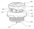
도 1은 본 발명의 일 실시예에 따른 음료용기의 사시도.
도 2는 도 1에 도시된 음료용기의 A-A'선에 따른 단면도.
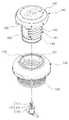
도 3은 도 1에 도시된 음료용기의 용기본체, 외부마개, 내부마개 및 스토퍼가 분리된 분해사시도.
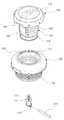
도 4는 도 3에 도시된 내부마개의 분해사시도.
도 5는 도 1에 도시된 음료용기에 포함되는 외부마개, 내부마개 및 스토퍼가 조립된 조립체를 상측에서 바라본 사시도.
도 6은 도 5에 도시된 외부마개, 내부마개 및 스토퍼가 조립된 조립체를 하측에서 바라본 사시도.
도 7 및 도 8은 도 5에 도시된 외부마개, 내부마개 및 스토퍼가 분리된 분해사시도.
도 9는 도 5에 도시된 내부마개가 열려서 추출구가 개방된 상태를 상측에서 바라본 사시도.
도 10은 도 5에 도시된 내부마개가 열려서 추출구가 개방된 상태를 하측에서 바라본 사시도.
도 11은 도 5에 도시된 내부마개가 닫혀서 추출구가 폐쇄된 상태의 측단면도.
도 12는 도 5에 도시된 내부마개가 열려서 추출구가 개방된 상태의 측단면도.
도 13은 스토퍼의 다른 일 실시형태를 나타내는 분해사시도.
도 14는 스토퍼의 또 다른 일 실시형태를 나타내는 분해사시도.1 is a perspective view of a beverage container according to an embodiment of the present invention;
2 is a cross-sectional view taken along line A-A 'of the beverage container shown in Fig. 1;
3 is an exploded perspective view showing the container body, the outer stopper, the inner stopper, and the stopper of the beverage container shown in FIG.
FIG. 4 is an exploded perspective view of the inner stopper shown in FIG. 3; FIG.
FIG. 5 is a perspective view of an assembly including an outer stopper, an inner stopper, and a stopper included in the beverage container shown in FIG. 1 viewed from above; FIG.
6 is a perspective view from below of an assembly with an outer stopper, an inner stopper, and a stopper shown in Fig. 5; Fig.
7 and 8 are exploded perspective views showing the outer stopper, the inner stopper, and the stopper shown in Fig. 5 separated; Fig.
FIG. 9 is a perspective view of the state in which the extraction stopper is opened with the inner stopper shown in FIG. 5 opened; FIG.
FIG. 10 is a perspective view of the state where the inner stopper shown in FIG. 5 is opened and the extraction port is opened from the lower side.
11 is a side cross-sectional view of the state in which the extraction stop is closed with the inner stopper shown in Fig. 5 being closed.
12 is a side cross-sectional view of the state in which the extraction plug is opened with the inner stopper shown in Fig. 5 being opened;
13 is an exploded perspective view showing another embodiment of the stopper;
14 is an exploded perspective view showing still another embodiment of the stopper;
본 명세서에서 사용한 용어는 단지 특정한 실시예를 설명하기 위해 사용된 것으로, 본 발명을 한정하려는 의도가 아니다. 또한, 본 명세서에서 단수의 표현은 문맥상 명백하게 다르게 뜻하지 않는 한, 복수의 표현을 포함한다.
The terminology used herein is for the purpose of describing particular embodiments only and is not intended to be limiting of the invention. Furthermore, the singular forms "a", "an," and "the" include plural referents unless the context clearly dictates otherwise.
이하, 첨부한 도면을 참고로 하여 본 발명의 바람직한 실시예에 대하여 설명한다.Hereinafter, preferred embodiments of the present invention will be described with reference to the accompanying drawings.
도 1 내지 도 14를 참조하여, 본 발명의 일 실시예에 따른 음료용기에 대해서 살펴본다.1 to 14, a beverage container according to an embodiment of the present invention will be described.
도 1 내지 도 14에 도시된 바와 같이, 본 발명의 일 실시예에 따른 음료용기(100)는 용기본체(110), 캡부재(120), 외부마개(130), 내부마개(140), 추출유로(150) 및 스토퍼(170)를 포함할 수 있다.
1 to 14, a
상기 용기본체(110)는 개구부(112)를 구비하며, 내부에 음료가 저장될 수 있는 공간을 구비할 수 있다.The
일 실시예에서, 용기본체(110)는 상단에 개구부(112)가 형성된 원통형태로 구성될 수 있으나, 이에 한정되는 것은 아니며, 용기본체(110)의 형상 및 개구부(112)의 위치는 실시형태에 따라 다양하게 변경될 수 있다.The shape of the
또한, 일 실시예에서, 용기본체(110)는 내면이 스테인리스 재질로 이루어지고 보온성능을 가지는 재질 및 구조로 구성될 수 있으나, 이에 한정되는 것은 아니다.In an embodiment, the inner surface of the
또한, 일 실시예에서, 개구부(112)의 내주면에는 후술할 외부마개(130)의 외측나사산(132)에 정방향으로 나사결합되는 체결나사산(114)이 형성될 수 있다.Also, in one embodiment, the inner circumferential surface of the
여기서, 정방향 나사결합은 시계방향으로 회전시 결합되고 반시계 방향으로 회전시 풀리는 결합구조를 의미한다. 이와 반대로, 후술할 역방향 나사결합은 시계방향으로 회전시 풀리고 반시계 방향으로 회전시 결합되는 결합구조를 의미한다.
Here, the forward screw coupling means a coupling structure that is engaged when rotating in the clockwise direction and is disengaged when rotated in the counterclockwise direction. On the contrary, the reverse screw coupling described below means a coupling structure that is released when rotated in the clockwise direction and engaged when rotated in the counterclockwise direction.
상기 캡부재(120)는 도 1 및 도 2에 도시된 바와 같이 후술할 외부마개(130) 및 내부마개(140)를 덮도록 용기본체(110)의 상단에 체결될 수 있다.The
이러한 캡부재(120)는 용기본체(110)에서 분리하여 컵으로 사용될 수도 있다.
The
상기 외부마개(130)는 용기본체(110)의 개구부(112)에 체결가능하며, 몸체를 중공형태로 관통하는 추출구(131)를 구비할 수 있다.The
여기서, 상기 추출구(131)는 외부마개(130)가 용기본체(110)에 체결되는 경우에 개구부(112)와 소통될 수 있다.Here, the
일 실시예에서, 외부마개(130)는 외측나사산(132)과 내측나사산(133)을 구비할 수 있다.In one embodiment,
상기 외측나사산(132)은 외부마개(130)의 외주면에 형성되어 상기 체결나사산(114)에 정방향으로 나사결합될 수 있다.The
그리고, 상기 내측나사산(133)은 외부마개(130)의 내주면에 형성되어 후술할 내부마개(140)에 형성된 개폐나사산(143)에 정방향으로 나사결합될 수 있다.The
또한, 일 실시예에서, 외부마개(130)의 하단에는 외부마개(130)와 용기본체(110) 사이를 수밀하게 실링할 수 있는 패킹부(134)가 구비될 수 있다.In an exemplary embodiment, a
일 예로, 상기 패킹부(134)는 실리콘으로 구성될 수 있으나, 이에 한정되는 것은 아니다For example, the
또한, 일 실시예에서, 외부마개(130)의 저면은 음료에 대해 내부식성이 강한 스테인리스 재질로 구성될 수 있으며, 이때, 상기 패킹부(134)는 외부마개(130)의 저면의 외곽을 따라 구비될 수 있다.In addition, in one embodiment, the bottom surface of the
한편, 외부마개(130)는 전술한 바와 같이 용기본체(110)에 나사결합되는 구조에 한정되지 않고, 개구부(112)에 슬라이드 삽입되며 용기본체(110)의 상방으로 당겨지는 당김 동작을 통해 열리도록 구성될 수도 있다.The
또한, 일 실시예에서, 이러한 외부마개(130)는 후술할 내부마개(140)가 상승되어 소정 거리만큼 열린 이후 내부마개(140)의 열림 동작에 연동하여 열릴 수 있다. 즉, 외부마개(130)는 용기본체(110)에서 내부마개(140)와 독립적으로 열릴 수도 있지만, 일정한 조건이 만족되는 경우에 내부마개(140)의 열림 동작에 연동하여 용기본체(110)에 열릴 수 있다.In addition, in one embodiment, the
여기서, 외부마개(130)가 내부마개(140)의 열림 동작에 연동하여 열리는 구조에 대해서는 내부마개(140) 및 스토퍼(170)를 설명한 후 상세히 설명하도록 한다.The
또한, 상기 소정 거리는 내부마개(140)가 완전히 닫힌 경우에 외부마개의 하단과 스토퍼(170) 간의 거리로 설정될 수 있다.
Further, the predetermined distance may be set to a distance between the lower end of the outer stopper and the
상기 내부마개(140)는 외부마개(130)의 추출구(131)에 삽입 결합되고, 상하로 이동하여 추출구(131)를 개폐할 수 있다.The
일 실시예에서, 내부마개(140)는 추출구(131)의 내측나사산(133)에 정방향으로 나사결합되고 추출구(131)를 개폐할 수 있다.In one embodiment, the
즉, 내부마개(140)는 반시계 방향으로 회전되어 나사결합이 풀리는 경우에 외부마개(130)의 상측으로 이동되어 추출구(131)를 개방할 수 있고, 시계방향으로 회전되어 외부마개(130)에 결합되는 경우에 외부마개(130)에 밀착되어 추출구(131)를 폐쇄할 수 있다.That is, when the
이를 위해, 일 실시예에서, 내부마개(140)는 결합몸체(141)와 손잡이(142)를 포함할 수 있다.To this end, in one embodiment, the
상기 결합몸체(141)는 추출구(131)에 삽입될 수 있는 원기둥 형태의 부분이다.The
일 실시예에서, 결합몸체(141)의 외주면에는 상기 내측나사산(133)에 나사결합될 수 있는 개폐나사산(143)이 형성될 수 있다.In one embodiment, the outer peripheral surface of the
상기 손잡이(142)는 결합몸체(141)의 상단에 구비되며, 추출구(131)의 면적보다 넓은 단면적을 가지는 형태로 구성될 수 있다.The
일 실시예에서, 손잡이(142)는 커버체결부(142a), 커버(142b) 및 파지부(142c)를 포함할 수 있다.In one embodiment, the
상기 커버체결부(142a)는 도 4에 도시된 바와 같이 결합몸체(141)의 상단 일부가 수평방향으로 확장되어 형성될 수 있다.As shown in FIG. 4, the
즉, 커버체결부(142a)는 결합몸체(141)에 일체로 형성되며, 결합몸체(141)의 상단의 직경이 확장되어 원반형태로 형성될 수도 있다.That is, the
상기 커버(142b)는 커버체결부(142a)의 상단을 덮도록 구비될 수 있다. 이러한 커버(142b)는 후술할 파지부(142c)와 결합되어, 파지부(142c)를 커버체결부(142a)에 견고하게 고정시키는 기능을 수행할 수 있다.The
상기 파지부(142c)는 커버체결부(142a)의 둘레를 둘러싸도록 커버체결부(142a)에 결합될 수 있다.The
사용자는 손으로 파지부(142c) 를 잡고 내부마개(140)를 회전시킬 수 있다.The user can hold the
일 실시예에서, 파지부(142c)는 사용자의 손에 높은 마찰력을 부여할 수 있도록 실리콘 재질로 이루어질 수 있으나, 이에 한정되는 것은 아니다.In one embodiment, the
또한, 일 실시예에서, 파지부(142c)에는 추출가이드홈(160)이 형성될 수 있다.Further, in one embodiment, the
상기 추출가이드홈(160)은 파지부(142c)의 외면에 손잡이(142)의 반경방향으로 연장된 오목한 홈 형태로 형성될 수 있다.The
또한, 추출가이드홈(160)은 파지부(142c)이 외면에 외측 상측으로 경사지게 형성될 수 있다.In addition, the
이러한 추출가이드홈(160)은 후술할 추출유로(150)에 연결될 수 있다.The
추출가이드홈(160)은 후술할 추출유로(150)에서 추출되는 음료가 파지부(142c)의 표면을 따라 넓게 퍼지지 않고 좁은 형태로 안정적으로 따라질 수 있도록 음료를 가이드 할 수 있다.The
일 실시예에서, 추출가이드홈(160)은 후술할 추출유로(150)가 복수개 형성되는 경우에 각각이 추출유로(150)에 일대일로 대응하여 복수개가 형성될 수 있다.In one embodiment, a plurality of
또한, 일 실시예에서, 내부마개(140)의 하단에는 내부마개(140)와 외부마개(130) 사이를 수밀하게 실링하는 실리콘부(144)가 구비될 수도 있다.In an embodiment, the lower end of the
이러한 실리콘부(144)는 내부마개(140)가 완전하게 닫힌 경우에 외부마개(130)의 패킹부(134)에 밀착되어 추출구(131) 및 후술할 추출유로(150)를 수밀하게 폐쇄할 수 있다.When the
또한, 일 실시예에서, 내부마개(140)의 하단에는 후술할 스토퍼(170)의 역나사부(171)가 역방향으로 나사결합될 수 있는 역나사구멍이 형성될 수 있다.Also, in one embodiment, a reverse screw hole may be formed at the lower end of the
일 예로, 내부마개(140)의 하단 중앙에는 스테인리스 재질로 이루어진 결합심부가 구비될 수 있고, 상기 역나사구멍은 상기 결합심부에 형성될 수 있다. 여기서, 상기 실리콘부(144)는 나부마개(140)의 저면 중에서 결합심부를 제외한 나머지 면을 덮는 형태로 구성될 수 있다.
For example, the lower end of the
상기 추출유로(150)는 외부마개(130)의 내주면 및 내부마개(140)의 외주면 중 적어도 하나에 형성되며, 내부마개(140)의 개폐동작에 따라 개폐될 수 있다.The
일 실시예에서, 추출유로(150)는 도 7 내지 도 10에 도시된 바와 같이 내부마개(140)의 외주면에 내부마개(140)의 길이방향으로 길게 형성된 오목한 홈 형태로 형성될 수 있다.7 to 10, the
또한, 도시하지는 않았지만, 추출유로(150)는 외부마개(130)의 내주면에 형서될 수도 있다. 예를 들어, 외부마개(130)의 내주면에 형성되는 추출유로(150)는 외부마개(130)의 내측나사산(133)의 일부 구간이 배제되는 형태로 구성될 수 있다.Further, although not shown, the
일 실시예에서, 도 9, 도 10 및 도 12에 도시된 바와 같이 내부마개(140)가 열려서 상측으로 이동되면 내부마개(140)의 실리콘부(144)와 외부마개(130)의 패킹부(134)가 서로 이격될 수 있다.9, 10 and 12, when the
이때, 내부마개(140)의 실리콘부(144)와 외부마개(130)의 패킹부(134) 사이의 간격으로 음료가 추출될 수 있고, 추출되는 음료는 추출유로(150) 및 추출가이드홈(160)을 따라 유동할 수 있게 된다.
At this time, the beverage can be extracted at a distance between the
상기 스토퍼(170)는 내부마개(140)에 체결 및 분리될 수 있고, 내부마개(140)에 체결된 경우에 외부마개(130)에 걸려서 내부마개(140)가 열리는 거리를 제한할 수 있다.The
다시 말해, 스토퍼(170)는 내부마개(140)가 상측으로 열리는 길이를 제한하여, 내부마개(140)가 외부마개(130)에서 완전히 이탈되는 것을 방지할 수 있다.In other words, the
또한, 이러한 스토퍼(170)는 내부마개(140)가 소정 거리만큼 열린 경우에 외부마개(130)와 내부마개(140)의 거동을 일치시킬 수 있다.The
즉, 스토퍼(170)는 외부마개(130)와 내부마개(140)가 슬라이드 삽입되는 형태로 개폐되는 실시예에서 내부마개(140)가 상방으로 인출되면 내부마개(140)가 소정 거리만큼 인출된 경우에 외부마개(130)의 하단에 걸려서 내부마개(140)의 인출동작에 연동하여 외부마개(130)가 내부마개(140)를 인출하는 힘보다 더 큰 힘을 통해 인출되도록 구성될 수 있다.That is, in the embodiment where the
이와 달리, 전술한 바와 같이 외부마개(130) 및 내부마개(140)가 정방향으로 나사결합되는 실시예에서, 스토퍼(170)는 내부마개(140)가 소정 거리만큼 열린 경우에 내부마개(140)의 회전력을 외부마개(130)에 전달하도록 구성될 수 있다.Alternatively, in the embodiment in which the
이러한 동작을 구현하기 위해, 일 실시예에서, 스토퍼(170)는 내부마개(140)에 역방향으로 나사결합될 수 있다.To implement this operation, in one embodiment, the
이를 위해, 일 실시예에서, 스토퍼(170)는 역나사부(171), 걸림부(172) 및 단턱부(174)를 포함할 수 있다.To this end, in one embodiment, the
상기 역나사부(171)는 내부마개(140)의 역나사구멍에 역방향으로 나사결합되는 부분으로서, 스토퍼(170)를 내부마개(140)에 고정시킬 수 있다.The reverse threaded
이러한 역나사부(171)는 역방향 나사결합이 이루어지면, 전술한 정방향 나사결합과 반대로, 시계방향으로 회전되는 경우 역나사구멍에서 나사결합이 풀릴 수 있고, 반시계 방향으로 회전되는 경우 역나사구멍에 더욱 깊게 삽입될 수 있다.This reverse threaded
상기 걸림부(172)는 역나사부(171)의 하단에 구비되며, 외부마개(130)의 하단에 걸리도록 구성될 수 있다.The
일 실시예에서, 걸림부(172)는 역나사부(171)의 하단에 수평방향으로 돌출된 바 형태로 구성될 수 있다.In one embodiment, the latching
일 예로, 걸림부(172)는 수평방향으로 연장된 봉 형상으로 이루어질 수 있다.For example, the latching
일 실시예에서, 걸림부(172)는 역나사부(171)와 일체로 구성될 수 있다.In one embodiment, the latching
한편, 도 13 및 도 14에는 걸림부(172)의 다른 일 실시형태가 도시되어 있다.On the other hand, another embodiment of the latching
다른 일 실시예에서, 걸림부(172)는 스토퍼(170)에서 분리 가능하도록 구성될 수 있다.In another embodiment, the latching
일 예로, 걸림부(172)는 봉 형상으로 이루어질 수 있으며, 역나사부(171)의 하단에는 걸림부(172)가 관통결합될 수 있는 결합구멍(175)이 형성될 수 있다.For example, the engaging
이러한 다른 일 실시예에서, 사용자는 스토퍼(170)의 기능을 사용하지 않고자 할 때 걸림부(172)를 분리하여 스토퍼(170)의 기능이 없는 상태로 사용할 수도 있다.In this other embodiment, when the user does not want to use the function of the
또한, 분리 가능한 걸림부(172)의 파생적인 기능으로서, 분리된 걸림부(172)는 음료가 저장된 용기본체(110)의 내부에 수납되어 음료를 섞는 교반용 구슬 기능을 수행할 수도 있다.In addition, as a derivative function of the
상기 단턱부(174)는 역나사부(171)의 끝단의 외주면에 반경방향을 돌출되어, 역나사부(171)가 역나사구멍에 삽입되는 길이를 제한할 수 있다.The
한편, 일 실시예에서, 스토퍼(170)는 스테인리스 재질로 이루어질 수 있다.Meanwhile, in one embodiment, the
스테인리스 재질은 음료에 의해 부식되지 않으므로, 음료를 위생적으로 보관할 수 있게 한다는 장점이 있다.Stainless steel materials are not corroded by beverages, so they can be stored hygienically.
이와 같은 구성을 가지는 스토퍼(170)는 역나사부(171)가 내부마개(140)에 전체가 인입되어 결합되고 내부마개(140)가 추출구(131)를 밀폐한 경우 걸림부(172)가 외부마개(130)의 하단에서 이격되도록 구성될 수 있다.The
따라서, 내부마개(140)는 걸림부(172)와 외부마개(130)의 하단 간의 간격만큼 열릴 수 있다.Accordingly, the
여기서, 사용자는 역나사부(171)의 나사결합 길이를 조절함으로써, 내부마개(140)가 열리는 간격을 조절할 수도 있다.
Here, the user may adjust the interval at which the
전술한 바와 같은 본 발명의 실시예들에 따른 음료용기(100)는 내부마개(140)를 열고 음료를 따르는 경우에 내부마개(140)가 열리는 거리를 제한하는 스토퍼(170)를 통해 내부마개(140)가 용기본체(110)에서 분리되지 않을 수 있다. 따라서, 내부마개(140)를 과도하게 열고 용기본체(110)를 기울여서 음료를 따르는 경우에도 내부마개(140)가 용기본체(110)에서 분리되어 많은 양의 음료가 쏟아지는 문제가 발생하지 않을 수 있다.The
또한, 본 발명의 실시예들에 따른 음료용기(100)는 내부마개(140)를 역방향으로 회전시켜 여는 경우 소정 간격이상 내부마개(140)가 열리면 스토퍼(170)와 내부마개(140)가 협력하여 내부마개(140)의 회전력을 외부마개(130)에 전달시킴으로써 외부마개(130)가 열리도록 할 수 있다.In the
구체적으로, 내부마개(140)가 소정 간격이상 계속 열리는 경우, 스토퍼(170)의 걸림부(172)가 외부마개(130)의 하단에 걸려서 스토퍼(170)의 회전이 정지되고 내부마개(140)의 역방향 회전에 따라 스토퍼(170)가 내부마개(140)에 대해 상대적으로 정방향으로 회전되게 된다. 이를 통해, 내부마개(140)의 개폐나사산(143)과 스토퍼(170)의 걸림부(172)가 외부마개(130)의 몸체를 상하로 강하게 가압함으로써, 내부마개(140)의 회전력이 외부마개(130)에 전달될 수 있게 된다.When the
이와 같은 구조에서, 사용자는 내부마개(140)만 파지한 채 1차적으로 내부마개(140)를 열 수 있으며, 내부마개(140)를 여는 동작을 계속 수행하여 2차적으로 외부마개(130)도 열 수 있다.
In this structure, the user can open the
본 발명은 특정한 실시예에 관하여 도시하고 설명하였지만, 당업계에서 통상의 지식을 가진 자라면 이하의 특허청구범위에 기재된 본 발명의 사상 및 영역을 벗어나지 않는 범위 내에서 본 발명을 다양하게 수정 및 변경시킬 수 있음을 밝혀두고자 한다.While the present invention has been particularly shown and described with reference to particular embodiments thereof, it is evident that many alternatives, modifications and variations will be apparent to those skilled in the art without departing from the spirit and scope of the invention as defined by the following claims I would like to make it clear.
100: 음료용기110: 용기본체
112: 개구부114: 체결나사산
120: 캡부재130: 외부마개
131: 추출구132: 외측나사산
133: 내측나사산134: 패킹부
140: 내부마개141: 결합몸체
142: 손잡이142a: 커버체결부
142b: 커버142c: 파지부
143: 개폐나사산144: 실리콘부
146: 결합심부147: 역나사구멍
150: 추출유로160: 추출가이드홈
170: 스토퍼171: 역나사부
172: 걸림부174: 단턱부
175: 결합구멍100: beverage container 110: container body
112: opening 114: fastening thread
120: cap member 130: outer cap
131: extraction port 132: external thread
133: Inner thread 134: Packing part
140: inner stopper 141: engaging body
142:
142b:
143: open / closed thread 144: silicone part
146: coupling deep 147: reverse screw hole
150: Extraction channel 160: Extraction guide groove
170: Stopper 171: Reverse thread portion
172: fastening portion 174: stepped portion
175: engaging hole
Claims (15)
Translated fromKorean상기 개구부에 체결가능하며, 상기 개구부와 소통되는 추출구를 구비하는 외부마개;
상기 추출구에 삽입 결합되고, 상하로 이동하며 상기 추출구를 개폐하는 내부마개;
상기 외부마개의 내주면 및 상기 내부마개의 외주면 중 적어도 하나에 형성되며, 상기 내부마개의 개폐동작에 따라 개폐되는 추출유로; 및
상기 내부마개에 체결되고 상기 외부마개에 걸려서 상기 내부마개가 열리는 거리를 제한하는 스토퍼;를 포함하고,
상기 외부마개는 상기 내부마개가 소정 거리만큼 열린 이후 상기 내부마개의 열림 동작에 연동하여 열릴 수 있는 음료용기.
A container body having an opening;
An outer cap which is fastened to the opening and has an extraction port communicating with the opening;
An inner cap inserted into the extraction port and moving up and down to open and close the extraction port;
An extraction duct formed on at least one of an inner circumferential surface of the outer stopper and an outer circumferential surface of the inner stopper and opened and closed according to an opening / closing operation of the inner stopper; And
And a stopper fastened to the inner stopper and restricting a distance at which the inner stopper is opened by being caught by the outer stopper,
Wherein the outer stopper can be opened in conjunction with the opening operation of the inner stopper after the inner stopper is opened by a predetermined distance.
상기 스토퍼는 상기 내부마개가 상기 소정 거리만큼 열린 경우에 상기 외부마개와 상기 내부마개의 거동을 일치시키는 음료용기.
The method according to claim 1,
Wherein the stopper coincides the behavior of the outer stopper and the inner stopper when the inner stopper is opened by the predetermined distance.
상기 외부마개는 상기 용기본체의 개구부에 나사결합되고,
상기 내부마개는 상기 외부마개의 추출구에 나사결합되는 음료용기.
The method according to claim 1,
Wherein the outer stopper is screwed to the opening of the container body,
Wherein the inner stopper is screwed to an extraction port of the outer stopper.
상기 스토퍼는 상기 내부마개가 상기 소정 거리만큼 열린 경우에 상기 내부마개의 회전력을 상기 외부마개에 전달하도록 구성된 음료용기.
The method of claim 3,
Wherein the stopper is configured to transmit the rotational force of the inner stopper to the outer stopper when the inner stopper is opened by the predetermined distance.
상기 외부마개는 상기 용기본체의 개구부에 정방향으로 나사결합되고,
상기 내부마개는 상기 외부마개의 추출구에 정방향으로 나사결합되며,
상기 스토퍼는 상기 내부마개에 역방향으로 나사결합되는 음료용기.
5. The method of claim 4,
Wherein the outer stopper is screwed to the opening of the container body in a forward direction,
The inner stopper is screwed in a forward direction to an extraction port of the outer stopper,
Wherein the stopper is screwed to the inner stopper in a reverse direction.
상기 내부마개는 상기 외부마개의 상방으로 개방되도록 구성되고,
상기 스토퍼는 상기 외부마개의 하단에 걸리도록 구성된 음료용기.
6. The method of claim 5,
Wherein the inner cap is configured to open upwardly of the outer cap,
And the stopper is adapted to be caught by the lower end of the outer stopper.
상기 스토퍼는,
내부마개에 역방향으로 나사결합되는 역나사부; 및
상기 외부마개의 하단에 걸리는 걸림부;를 포함하는 음료용기.
The method according to claim 6,
The stopper
A reverse threaded portion screwed backwardly on the inner stopper; And
And an engaging portion which is engaged with a lower end of the outer stopper.
상기 스토퍼는, 상기 역나사부가 상기 내부마개에 전체가 인입되어 결합되고 상기 내부마개가 상기 추출구를 밀폐한 경우 상기 걸림부가 상기 외부마개의 하단에서 이격되도록 구성된 음료용기.
8. The method of claim 7,
Wherein the stopper is configured such that the stopper portion is spaced apart from the lower end of the outer stopper when the reverse stopper portion is entirely inserted into the inner stopper and the inner stopper hermetically seals the stopper.
상기 스토퍼는 상기 역나사부와 상기 걸림부가 일체로 구성된 음료용기.
8. The method of claim 7,
Wherein the stopper has the reverse screw portion and the engagement portion integrally formed.
상기 걸림부는 상기 역나사부에 체결 및 분리 가능하도록 구성된 음료용기.
8. The method of claim 7,
And the engaging portion is configured to be fastened and detachable to the reverse threaded portion.
상기 스토퍼는 스테인리스 재질로 이루어진 음료용기.
The method according to claim 1,
Wherein the stopper is made of stainless steel.
상기 내부마개의 하단에는 실리콘부가 구비되는 음료용기.
The method according to claim 1,
Wherein a silicone part is provided at a lower end of the inner stopper.
상기 내부마개는 상기 추출구에 나사결합되는 결합몸체와, 상기 결합몸체의 상단에 구비되는 손잡이를 포함하고,
상기 손잡이에는 상기 추출구에 연결되는 추출가이드홈이 형성된 음료용기.
The method according to claim 1,
Wherein the inner stopper includes a coupling body screwed to the extraction port and a handle provided at an upper end of the coupling body,
And an extraction guide groove connected to the extraction port is formed in the handle.
상기 손잡이는,
상기 결합몸체의 상단 일부가 수평방향으로 확장되어 형성된 커버체결부;
상기 커버체결부의 상단을 덮도록 구비되는 커버; 및
상기 커버체결부의 둘레를 둘러싸도록 상기 커버체결부에 결합되는 파지부;를 포함하고,
상기 추출가이드홈은 상기 파지부에 형성되는 음료용기.
14. The method of claim 13,
The handle
A cover fastening part formed by horizontally extending a part of an upper end of the coupling body;
A cover provided to cover an upper end of the cover fastening portion; And
And a grip portion coupled to the cover fastening portion so as to surround the periphery of the cover fastening portion,
Wherein the extraction guide groove is formed in the grip portion.
상기 추출가이드홈은 상기 파지부의 외면에 외측 상측으로 경사지게 형성된 음료용기.15. The method of claim 14,
And the extraction guide groove is inclined toward the upper side on the outer surface of the grip portion.
Priority Applications (1)
| Application Number | Priority Date | Filing Date | Title |
|---|---|---|---|
| KR1020150143459AKR101785906B1 (en) | 2015-10-14 | 2015-10-14 | Drink container |
Applications Claiming Priority (1)
| Application Number | Priority Date | Filing Date | Title |
|---|---|---|---|
| KR1020150143459AKR101785906B1 (en) | 2015-10-14 | 2015-10-14 | Drink container |
Publications (2)
| Publication Number | Publication Date |
|---|---|
| KR20170043856A KR20170043856A (en) | 2017-04-24 |
| KR101785906B1true KR101785906B1 (en) | 2017-10-16 |
Family
ID=58704456
Family Applications (1)
| Application Number | Title | Priority Date | Filing Date |
|---|---|---|---|
| KR1020150143459AActiveKR101785906B1 (en) | 2015-10-14 | 2015-10-14 | Drink container |
Country Status (1)
| Country | Link |
|---|---|
| KR (1) | KR101785906B1 (en) |
Cited By (14)
| Publication number | Priority date | Publication date | Assignee | Title |
|---|---|---|---|---|
| USD860716S1 (en) | 2017-03-27 | 2019-09-24 | Yeti Coolers, Llc | Container lid |
| USD871133S1 (en) | 2018-10-17 | 2019-12-31 | Yeti Coolers, Llc | Lid |
| USD876905S1 (en) | 2015-11-20 | 2020-03-03 | Yeti Coolers, Llc | Jug |
| USD883737S1 (en) | 2018-10-17 | 2020-05-12 | Yeti Coolers, Llc | Lid |
| USD883738S1 (en) | 2018-10-17 | 2020-05-12 | Yeti Coolers, Llc | Lid |
| USD896572S1 (en) | 2018-08-20 | 2020-09-22 | Yeti Coolers, Llc | Container lid |
| USD897151S1 (en) | 2018-10-17 | 2020-09-29 | Yeti Coolers, Llc | Lid |
| US10926925B2 (en) | 2015-08-14 | 2021-02-23 | Yeti Coolers, Llc | Container with magnetic cap |
| US10959553B2 (en) | 2016-10-17 | 2021-03-30 | Yeti Coolers, Llc | Container and method of forming a container |
| US10959552B2 (en) | 2016-10-17 | 2021-03-30 | Yeti Coolers, Llc | Container and method of forming a container |
| US11021314B2 (en) | 2016-10-17 | 2021-06-01 | Yeti Coolers, Llc | Container and method of forming a container |
| US11034505B2 (en) | 2016-10-17 | 2021-06-15 | Yeti Coolers, Llc | Container and method of forming a container |
| WO2024254306A1 (en)* | 2023-06-07 | 2024-12-12 | Yeti Coolers, Llc | Lid assembly for beverage container |
| US20250074667A1 (en)* | 2020-12-14 | 2025-03-06 | Awl In Ip Pty Ltd. | A drinks container |
Families Citing this family (3)
| Publication number | Priority date | Publication date | Assignee | Title |
|---|---|---|---|---|
| US10543960B2 (en)* | 2017-11-28 | 2020-01-28 | Thermos L.L.C. | Lid for a beverage container |
| CN107989399A (en)* | 2017-12-20 | 2018-05-04 | 佛山科学技术学院 | A kind of intelligent concrete prosthetic device |
| KR102484359B1 (en)* | 2020-09-30 | 2023-01-02 | 김학래 | Liquid container for easy detachable parts |
Citations (1)
| Publication number | Priority date | Publication date | Assignee | Title |
|---|---|---|---|---|
| JP2006259759A (en) | 2006-04-26 | 2006-09-28 | Ricoh Co Ltd | Inner cap of toner container |
- 2015
- 2015-10-14KRKR1020150143459Apatent/KR101785906B1/enactiveActive
Patent Citations (1)
| Publication number | Priority date | Publication date | Assignee | Title |
|---|---|---|---|---|
| JP2006259759A (en) | 2006-04-26 | 2006-09-28 | Ricoh Co Ltd | Inner cap of toner container |
Cited By (33)
| Publication number | Priority date | Publication date | Assignee | Title |
|---|---|---|---|---|
| US11273961B2 (en) | 2015-08-14 | 2022-03-15 | Yeti Coolers, Llc | Container with magnetic cap |
| US10926925B2 (en) | 2015-08-14 | 2021-02-23 | Yeti Coolers, Llc | Container with magnetic cap |
| US12227340B2 (en) | 2015-08-14 | 2025-02-18 | Yeti Coolers, Llc | Container with magnetic cap |
| US11794960B2 (en) | 2015-08-14 | 2023-10-24 | Yeti Coolers, Llc | Container with magnetic cap |
| USD1018214S1 (en) | 2015-11-20 | 2024-03-19 | Yeti Coolers, Llc | Jug |
| USD960660S1 (en) | 2015-11-20 | 2022-08-16 | Yeti Coolers, Llc | Jug |
| USD876905S1 (en) | 2015-11-20 | 2020-03-03 | Yeti Coolers, Llc | Jug |
| USD899871S1 (en) | 2015-11-20 | 2020-10-27 | Yeti Coolers, Llc | Jug |
| USD1039919S1 (en) | 2015-11-20 | 2024-08-27 | Yeti Coolers, Llc | Jug |
| US10959552B2 (en) | 2016-10-17 | 2021-03-30 | Yeti Coolers, Llc | Container and method of forming a container |
| US11840365B2 (en) | 2016-10-17 | 2023-12-12 | Yeti Coolers, Llc | Container and method of forming a container |
| US10959553B2 (en) | 2016-10-17 | 2021-03-30 | Yeti Coolers, Llc | Container and method of forming a container |
| US12269666B2 (en) | 2016-10-17 | 2025-04-08 | Yeti Coolers, Llc | Container and method of forming a container |
| US11021314B2 (en) | 2016-10-17 | 2021-06-01 | Yeti Coolers, Llc | Container and method of forming a container |
| US11034505B2 (en) | 2016-10-17 | 2021-06-15 | Yeti Coolers, Llc | Container and method of forming a container |
| US11503932B2 (en) | 2016-10-17 | 2022-11-22 | Yeti Coolers, Llc | Container and method of forming a container |
| US11930944B2 (en) | 2016-10-17 | 2024-03-19 | Yeti Coolers, Llc | Container and method of forming a container |
| US11524833B2 (en) | 2016-10-17 | 2022-12-13 | Yeti Coolers, Llc | Container and method of forming a container |
| US11814235B2 (en) | 2016-10-17 | 2023-11-14 | Yeti Coolers, Llc | Container and method of forming a container |
| USD860716S1 (en) | 2017-03-27 | 2019-09-24 | Yeti Coolers, Llc | Container lid |
| USD1061140S1 (en) | 2018-08-20 | 2025-02-11 | Yeti Coolers, Llc | Container lid |
| USD896572S1 (en) | 2018-08-20 | 2020-09-22 | Yeti Coolers, Llc | Container lid |
| USD913745S1 (en) | 2018-08-20 | 2021-03-23 | Yeti Coolers, Llc | Container lid |
| USD913746S1 (en) | 2018-08-20 | 2021-03-23 | Yeti Coolers, Llc | Container lid |
| USD988789S1 (en) | 2018-08-20 | 2023-06-13 | Yeti Coolers, Llc | Container lid |
| USD883737S1 (en) | 2018-10-17 | 2020-05-12 | Yeti Coolers, Llc | Lid |
| USD871133S1 (en) | 2018-10-17 | 2019-12-31 | Yeti Coolers, Llc | Lid |
| USD935268S1 (en) | 2018-10-17 | 2021-11-09 | Yeti Coolers, Llc | Lid |
| USD883738S1 (en) | 2018-10-17 | 2020-05-12 | Yeti Coolers, Llc | Lid |
| USD1046619S1 (en) | 2018-10-17 | 2024-10-15 | Yeti Coolers, Llc | Lid |
| USD897151S1 (en) | 2018-10-17 | 2020-09-29 | Yeti Coolers, Llc | Lid |
| US20250074667A1 (en)* | 2020-12-14 | 2025-03-06 | Awl In Ip Pty Ltd. | A drinks container |
| WO2024254306A1 (en)* | 2023-06-07 | 2024-12-12 | Yeti Coolers, Llc | Lid assembly for beverage container |
Also Published As
| Publication number | Publication date |
|---|---|
| KR20170043856A (en) | 2017-04-24 |
Similar Documents
| Publication | Publication Date | Title |
|---|---|---|
| KR101785906B1 (en) | Drink container | |
| KR101581270B1 (en) | Drink container | |
| US9049885B2 (en) | Resealable spout for selectively accessing coconut water within a coconut | |
| US9745110B2 (en) | 360° pour beverage container | |
| CN109835599B (en) | Lid for beverage container | |
| JP2014210136A (en) | Plug body of beverage container | |
| KR200476831Y1 (en) | A tumbler | |
| US20160045047A1 (en) | Container with a Thermal Regulating Insert | |
| US20180265265A1 (en) | Beverage container lid | |
| US20170295985A1 (en) | Filter cup | |
| GB2399081A (en) | Container stopper | |
| US20190185306A1 (en) | Multifunction recreational apparatus | |
| CN203776590U (en) | Anti-reflux cup | |
| JP2023058102A (en) | Cap unit and container with cap | |
| KR20160131443A (en) | Thermal insulation cup is housed inside the handle | |
| KR200483826Y1 (en) | a wine cup | |
| JP6263401B2 (en) | Refill container | |
| KR200407277Y1 (en) | Four cap with adjustable discharge volume | |
| CN210276970U (en) | a container | |
| KR101690174B1 (en) | A Sanitary-cap For adding addition in use | |
| TWM492883U (en) | Pulling type beverage bottle cap assembly | |
| JP2014125240A (en) | Beverage container and lid for beverage container | |
| KR20170002464U (en) | Multifunctional bottle opener | |
| TWM583830U (en) | Bottle cap structure | |
| KR200200955Y1 (en) | Cap having temperature keeping function of a thermos bottle |
Legal Events
| Date | Code | Title | Description |
|---|---|---|---|
| A201 | Request for examination | ||
| PA0109 | Patent application | St.27 status event code:A-0-1-A10-A12-nap-PA0109 | |
| PA0201 | Request for examination | St.27 status event code:A-1-2-D10-D11-exm-PA0201 | |
| R18-X000 | Changes to party contact information recorded | St.27 status event code:A-3-3-R10-R18-oth-X000 | |
| R18-X000 | Changes to party contact information recorded | St.27 status event code:A-3-3-R10-R18-oth-X000 | |
| D13-X000 | Search requested | St.27 status event code:A-1-2-D10-D13-srh-X000 | |
| D14-X000 | Search report completed | St.27 status event code:A-1-2-D10-D14-srh-X000 | |
| E902 | Notification of reason for refusal | ||
| PE0902 | Notice of grounds for rejection | St.27 status event code:A-1-2-D10-D21-exm-PE0902 | |
| P11-X000 | Amendment of application requested | St.27 status event code:A-2-2-P10-P11-nap-X000 | |
| P13-X000 | Application amended | St.27 status event code:A-2-2-P10-P13-nap-X000 | |
| R18-X000 | Changes to party contact information recorded | St.27 status event code:A-3-3-R10-R18-oth-X000 | |
| PG1501 | Laying open of application | St.27 status event code:A-1-1-Q10-Q12-nap-PG1501 | |
| E701 | Decision to grant or registration of patent right | ||
| PE0701 | Decision of registration | St.27 status event code:A-1-2-D10-D22-exm-PE0701 | |
| GRNT | Written decision to grant | ||
| PR0701 | Registration of establishment | St.27 status event code:A-2-4-F10-F11-exm-PR0701 | |
| PR1002 | Payment of registration fee | St.27 status event code:A-2-2-U10-U11-oth-PR1002 Fee payment year number:1 | |
| PG1601 | Publication of registration | St.27 status event code:A-4-4-Q10-Q13-nap-PG1601 | |
| P22-X000 | Classification modified | St.27 status event code:A-4-4-P10-P22-nap-X000 | |
| R18-X000 | Changes to party contact information recorded | St.27 status event code:A-5-5-R10-R18-oth-X000 | |
| PR1001 | Payment of annual fee | St.27 status event code:A-4-4-U10-U11-oth-PR1001 Fee payment year number:4 | |
| PR1001 | Payment of annual fee | St.27 status event code:A-4-4-U10-U11-oth-PR1001 Fee payment year number:5 | |
| PR1001 | Payment of annual fee | St.27 status event code:A-4-4-U10-U11-oth-PR1001 Fee payment year number:6 | |
| PN2301 | Change of applicant | St.27 status event code:A-5-5-R10-R13-asn-PN2301 St.27 status event code:A-5-5-R10-R11-asn-PN2301 | |
| R18-X000 | Changes to party contact information recorded | St.27 status event code:A-5-5-R10-R18-oth-X000 | |
| PR1001 | Payment of annual fee | St.27 status event code:A-4-4-U10-U11-oth-PR1001 Fee payment year number:7 | |
| PR1001 | Payment of annual fee | St.27 status event code:A-4-4-U10-U11-oth-PR1001 Fee payment year number:8 | |
| PR1001 | Payment of annual fee | St.27 status event code:A-4-4-U10-U11-oth-PR1001 Fee payment year number:9 |