KR101781241B1 - Medicament delivery device comprising feedback signalling means - Google Patents
Medicament delivery device comprising feedback signalling meansDownload PDFInfo
- Publication number
- KR101781241B1 KR101781241B1KR1020127028493AKR20127028493AKR101781241B1KR 101781241 B1KR101781241 B1KR 101781241B1KR 1020127028493 AKR1020127028493 AKR 1020127028493AKR 20127028493 AKR20127028493 AKR 20127028493AKR 101781241 B1KR101781241 B1KR 101781241B1
- Authority
- KR
- South Korea
- Prior art keywords
- tubular
- drug
- plunger rod
- injection device
- extension
- Prior art date
- Legal status (The legal status is an assumption and is not a legal conclusion. Google has not performed a legal analysis and makes no representation as to the accuracy of the status listed.)
- Active
Links
- 239000003814drugSubstances0.000titleclaimsabstractdescription111
- 230000011664signalingEffects0.000title1
- 229940079593drugDrugs0.000claimsabstractdescription105
- 238000002347injectionMethods0.000claimsabstractdescription65
- 239000007924injectionSubstances0.000claimsabstractdescription65
- 230000004913activationEffects0.000claimsabstractdescription40
- 238000001802infusionMethods0.000claimsdescription42
- 230000000007visual effectEffects0.000claimsdescription18
- 230000003213activating effectEffects0.000claimsdescription13
- 238000000034methodMethods0.000claimsdescription13
- 230000007274generation of a signal involved in cell-cell signalingEffects0.000claimsdescription5
- 238000012377drug deliveryMethods0.000abstract1
- 238000012790confirmationMethods0.000description5
- 230000008569processEffects0.000description4
- 230000009471actionEffects0.000description3
- 210000001217buttockAnatomy0.000description2
- 230000035515penetrationEffects0.000description2
- 230000008859changeEffects0.000description1
- 239000000463materialSubstances0.000description1
- 239000012528membraneSubstances0.000description1
- 239000002184metalSubstances0.000description1
- 230000001681protective effectEffects0.000description1
- 230000002123temporal effectEffects0.000description1
Images


Classifications
- A—HUMAN NECESSITIES
- A61—MEDICAL OR VETERINARY SCIENCE; HYGIENE
- A61M—DEVICES FOR INTRODUCING MEDIA INTO, OR ONTO, THE BODY; DEVICES FOR TRANSDUCING BODY MEDIA OR FOR TAKING MEDIA FROM THE BODY; DEVICES FOR PRODUCING OR ENDING SLEEP OR STUPOR
- A61M5/00—Devices for bringing media into the body in a subcutaneous, intra-vascular or intramuscular way; Accessories therefor, e.g. filling or cleaning devices, arm-rests
- A61M5/178—Syringes
- A61M5/31—Details
- A61M5/315—Pistons; Piston-rods; Guiding, blocking or restricting the movement of the rod or piston; Appliances on the rod for facilitating dosing ; Dosing mechanisms
- A61M5/31565—Administration mechanisms, i.e. constructional features, modes of administering a dose
- A61M5/31566—Means improving security or handling thereof
- A61M5/3157—Means providing feedback signals when administration is completed
- A—HUMAN NECESSITIES
- A61—MEDICAL OR VETERINARY SCIENCE; HYGIENE
- A61M—DEVICES FOR INTRODUCING MEDIA INTO, OR ONTO, THE BODY; DEVICES FOR TRANSDUCING BODY MEDIA OR FOR TAKING MEDIA FROM THE BODY; DEVICES FOR PRODUCING OR ENDING SLEEP OR STUPOR
- A61M5/00—Devices for bringing media into the body in a subcutaneous, intra-vascular or intramuscular way; Accessories therefor, e.g. filling or cleaning devices, arm-rests
- A61M5/14—Infusion devices, e.g. infusing by gravity; Blood infusion; Accessories therefor
- A61M5/142—Pressure infusion, e.g. using pumps
- A61M5/145—Pressure infusion, e.g. using pumps using pressurised reservoirs, e.g. pressurised by means of pistons
- A—HUMAN NECESSITIES
- A61—MEDICAL OR VETERINARY SCIENCE; HYGIENE
- A61M—DEVICES FOR INTRODUCING MEDIA INTO, OR ONTO, THE BODY; DEVICES FOR TRANSDUCING BODY MEDIA OR FOR TAKING MEDIA FROM THE BODY; DEVICES FOR PRODUCING OR ENDING SLEEP OR STUPOR
- A61M5/00—Devices for bringing media into the body in a subcutaneous, intra-vascular or intramuscular way; Accessories therefor, e.g. filling or cleaning devices, arm-rests
- A61M5/178—Syringes
- A61M5/20—Automatic syringes, e.g. with automatically actuated piston rod, with automatic needle injection, filling automatically
- A61M5/2033—Spring-loaded one-shot injectors with or without automatic needle insertion
- A—HUMAN NECESSITIES
- A61—MEDICAL OR VETERINARY SCIENCE; HYGIENE
- A61M—DEVICES FOR INTRODUCING MEDIA INTO, OR ONTO, THE BODY; DEVICES FOR TRANSDUCING BODY MEDIA OR FOR TAKING MEDIA FROM THE BODY; DEVICES FOR PRODUCING OR ENDING SLEEP OR STUPOR
- A61M5/00—Devices for bringing media into the body in a subcutaneous, intra-vascular or intramuscular way; Accessories therefor, e.g. filling or cleaning devices, arm-rests
- A61M5/178—Syringes
- A61M5/24—Ampoule syringes, i.e. syringes with needle for use in combination with replaceable ampoules or carpules, e.g. automatic
- A—HUMAN NECESSITIES
- A61—MEDICAL OR VETERINARY SCIENCE; HYGIENE
- A61M—DEVICES FOR INTRODUCING MEDIA INTO, OR ONTO, THE BODY; DEVICES FOR TRANSDUCING BODY MEDIA OR FOR TAKING MEDIA FROM THE BODY; DEVICES FOR PRODUCING OR ENDING SLEEP OR STUPOR
- A61M5/00—Devices for bringing media into the body in a subcutaneous, intra-vascular or intramuscular way; Accessories therefor, e.g. filling or cleaning devices, arm-rests
- A61M5/178—Syringes
- A61M5/31—Details
- A61M5/315—Pistons; Piston-rods; Guiding, blocking or restricting the movement of the rod or piston; Appliances on the rod for facilitating dosing ; Dosing mechanisms
- A61M5/31501—Means for blocking or restricting the movement of the rod or piston
- A—HUMAN NECESSITIES
- A61—MEDICAL OR VETERINARY SCIENCE; HYGIENE
- A61M—DEVICES FOR INTRODUCING MEDIA INTO, OR ONTO, THE BODY; DEVICES FOR TRANSDUCING BODY MEDIA OR FOR TAKING MEDIA FROM THE BODY; DEVICES FOR PRODUCING OR ENDING SLEEP OR STUPOR
- A61M5/00—Devices for bringing media into the body in a subcutaneous, intra-vascular or intramuscular way; Accessories therefor, e.g. filling or cleaning devices, arm-rests
- A61M5/178—Syringes
- A61M5/31—Details
- A61M5/315—Pistons; Piston-rods; Guiding, blocking or restricting the movement of the rod or piston; Appliances on the rod for facilitating dosing ; Dosing mechanisms
- A61M5/31511—Piston or piston-rod constructions, e.g. connection of piston with piston-rod
- A61M5/31515—Connection of piston with piston rod
- A—HUMAN NECESSITIES
- A61—MEDICAL OR VETERINARY SCIENCE; HYGIENE
- A61M—DEVICES FOR INTRODUCING MEDIA INTO, OR ONTO, THE BODY; DEVICES FOR TRANSDUCING BODY MEDIA OR FOR TAKING MEDIA FROM THE BODY; DEVICES FOR PRODUCING OR ENDING SLEEP OR STUPOR
- A61M5/00—Devices for bringing media into the body in a subcutaneous, intra-vascular or intramuscular way; Accessories therefor, e.g. filling or cleaning devices, arm-rests
- A61M5/178—Syringes
- A61M5/31—Details
- A61M5/315—Pistons; Piston-rods; Guiding, blocking or restricting the movement of the rod or piston; Appliances on the rod for facilitating dosing ; Dosing mechanisms
- A61M5/31565—Administration mechanisms, i.e. constructional features, modes of administering a dose
- A61M5/31576—Constructional features or modes of drive mechanisms for piston rods
- A61M5/31578—Constructional features or modes of drive mechanisms for piston rods based on axial translation, i.e. components directly operatively associated and axially moved with plunger rod
- A61M5/3158—Constructional features or modes of drive mechanisms for piston rods based on axial translation, i.e. components directly operatively associated and axially moved with plunger rod performed by axially moving actuator operated by user, e.g. an injection button
- A—HUMAN NECESSITIES
- A61—MEDICAL OR VETERINARY SCIENCE; HYGIENE
- A61M—DEVICES FOR INTRODUCING MEDIA INTO, OR ONTO, THE BODY; DEVICES FOR TRANSDUCING BODY MEDIA OR FOR TAKING MEDIA FROM THE BODY; DEVICES FOR PRODUCING OR ENDING SLEEP OR STUPOR
- A61M5/00—Devices for bringing media into the body in a subcutaneous, intra-vascular or intramuscular way; Accessories therefor, e.g. filling or cleaning devices, arm-rests
- A61M5/178—Syringes
- A61M5/31—Details
- A61M5/315—Pistons; Piston-rods; Guiding, blocking or restricting the movement of the rod or piston; Appliances on the rod for facilitating dosing ; Dosing mechanisms
- A61M5/31565—Administration mechanisms, i.e. constructional features, modes of administering a dose
- A61M5/31576—Constructional features or modes of drive mechanisms for piston rods
- A61M5/31583—Constructional features or modes of drive mechanisms for piston rods based on rotational translation, i.e. movement of piston rod is caused by relative rotation between the user activated actuator and the piston rod
- A61M5/31585—Constructional features or modes of drive mechanisms for piston rods based on rotational translation, i.e. movement of piston rod is caused by relative rotation between the user activated actuator and the piston rod performed by axially moving actuator, e.g. an injection button
- A—HUMAN NECESSITIES
- A61—MEDICAL OR VETERINARY SCIENCE; HYGIENE
- A61M—DEVICES FOR INTRODUCING MEDIA INTO, OR ONTO, THE BODY; DEVICES FOR TRANSDUCING BODY MEDIA OR FOR TAKING MEDIA FROM THE BODY; DEVICES FOR PRODUCING OR ENDING SLEEP OR STUPOR
- A61M5/00—Devices for bringing media into the body in a subcutaneous, intra-vascular or intramuscular way; Accessories therefor, e.g. filling or cleaning devices, arm-rests
- A61M5/178—Syringes
- A61M5/31—Details
- A61M5/32—Needles; Details of needles pertaining to their connection with syringe or hub; Accessories for bringing the needle into, or holding the needle on, the body; Devices for protection of needles
- A61M5/3205—Apparatus for removing or disposing of used needles or syringes, e.g. containers; Means for protection against accidental injuries from used needles
- A61M5/321—Means for protection against accidental injuries by used needles
- A61M5/3243—Means for protection against accidental injuries by used needles being axially-extensible, e.g. protective sleeves coaxially slidable on the syringe barrel
- A—HUMAN NECESSITIES
- A61—MEDICAL OR VETERINARY SCIENCE; HYGIENE
- A61M—DEVICES FOR INTRODUCING MEDIA INTO, OR ONTO, THE BODY; DEVICES FOR TRANSDUCING BODY MEDIA OR FOR TAKING MEDIA FROM THE BODY; DEVICES FOR PRODUCING OR ENDING SLEEP OR STUPOR
- A61M5/00—Devices for bringing media into the body in a subcutaneous, intra-vascular or intramuscular way; Accessories therefor, e.g. filling or cleaning devices, arm-rests
- A61M5/178—Syringes
- A61M5/20—Automatic syringes, e.g. with automatically actuated piston rod, with automatic needle injection, filling automatically
- A61M2005/2006—Having specific accessories
- A61M2005/2013—Having specific accessories triggering of discharging means by contact of injector with patient body
- A—HUMAN NECESSITIES
- A61—MEDICAL OR VETERINARY SCIENCE; HYGIENE
- A61M—DEVICES FOR INTRODUCING MEDIA INTO, OR ONTO, THE BODY; DEVICES FOR TRANSDUCING BODY MEDIA OR FOR TAKING MEDIA FROM THE BODY; DEVICES FOR PRODUCING OR ENDING SLEEP OR STUPOR
- A61M5/00—Devices for bringing media into the body in a subcutaneous, intra-vascular or intramuscular way; Accessories therefor, e.g. filling or cleaning devices, arm-rests
- A61M5/178—Syringes
- A61M5/20—Automatic syringes, e.g. with automatically actuated piston rod, with automatic needle injection, filling automatically
- A61M2005/2073—Automatic syringes, e.g. with automatically actuated piston rod, with automatic needle injection, filling automatically preventing premature release, e.g. by making use of a safety lock
- A61M2005/208—Release is possible only when device is pushed against the skin, e.g. using a trigger which is blocked or inactive when the device is not pushed against the skin
- A—HUMAN NECESSITIES
- A61—MEDICAL OR VETERINARY SCIENCE; HYGIENE
- A61M—DEVICES FOR INTRODUCING MEDIA INTO, OR ONTO, THE BODY; DEVICES FOR TRANSDUCING BODY MEDIA OR FOR TAKING MEDIA FROM THE BODY; DEVICES FOR PRODUCING OR ENDING SLEEP OR STUPOR
- A61M5/00—Devices for bringing media into the body in a subcutaneous, intra-vascular or intramuscular way; Accessories therefor, e.g. filling or cleaning devices, arm-rests
- A61M5/178—Syringes
- A61M5/24—Ampoule syringes, i.e. syringes with needle for use in combination with replaceable ampoules or carpules, e.g. automatic
- A61M2005/2485—Ampoule holder connected to rest of syringe
- A—HUMAN NECESSITIES
- A61—MEDICAL OR VETERINARY SCIENCE; HYGIENE
- A61M—DEVICES FOR INTRODUCING MEDIA INTO, OR ONTO, THE BODY; DEVICES FOR TRANSDUCING BODY MEDIA OR FOR TAKING MEDIA FROM THE BODY; DEVICES FOR PRODUCING OR ENDING SLEEP OR STUPOR
- A61M2205/00—General characteristics of the apparatus
- A61M2205/58—Means for facilitating use, e.g. by people with impaired vision
- A61M2205/581—Means for facilitating use, e.g. by people with impaired vision by audible feedback
- A—HUMAN NECESSITIES
- A61—MEDICAL OR VETERINARY SCIENCE; HYGIENE
- A61M—DEVICES FOR INTRODUCING MEDIA INTO, OR ONTO, THE BODY; DEVICES FOR TRANSDUCING BODY MEDIA OR FOR TAKING MEDIA FROM THE BODY; DEVICES FOR PRODUCING OR ENDING SLEEP OR STUPOR
- A61M2205/00—General characteristics of the apparatus
- A61M2205/58—Means for facilitating use, e.g. by people with impaired vision
- A61M2205/582—Means for facilitating use, e.g. by people with impaired vision by tactile feedback
- A—HUMAN NECESSITIES
- A61—MEDICAL OR VETERINARY SCIENCE; HYGIENE
- A61M—DEVICES FOR INTRODUCING MEDIA INTO, OR ONTO, THE BODY; DEVICES FOR TRANSDUCING BODY MEDIA OR FOR TAKING MEDIA FROM THE BODY; DEVICES FOR PRODUCING OR ENDING SLEEP OR STUPOR
- A61M2205/00—General characteristics of the apparatus
- A61M2205/58—Means for facilitating use, e.g. by people with impaired vision
- A61M2205/583—Means for facilitating use, e.g. by people with impaired vision by visual feedback
- A61M2205/584—Means for facilitating use, e.g. by people with impaired vision by visual feedback having a color code
- A—HUMAN NECESSITIES
- A61—MEDICAL OR VETERINARY SCIENCE; HYGIENE
- A61M—DEVICES FOR INTRODUCING MEDIA INTO, OR ONTO, THE BODY; DEVICES FOR TRANSDUCING BODY MEDIA OR FOR TAKING MEDIA FROM THE BODY; DEVICES FOR PRODUCING OR ENDING SLEEP OR STUPOR
- A61M5/00—Devices for bringing media into the body in a subcutaneous, intra-vascular or intramuscular way; Accessories therefor, e.g. filling or cleaning devices, arm-rests
- A61M5/178—Syringes
- A61M5/31—Details
- A61M5/32—Needles; Details of needles pertaining to their connection with syringe or hub; Accessories for bringing the needle into, or holding the needle on, the body; Devices for protection of needles
- A61M5/3202—Devices for protection of the needle before use, e.g. caps
Landscapes
- Health & Medical Sciences (AREA)
- Engineering & Computer Science (AREA)
- Hematology (AREA)
- Anesthesiology (AREA)
- Biomedical Technology (AREA)
- Heart & Thoracic Surgery (AREA)
- Vascular Medicine (AREA)
- Life Sciences & Earth Sciences (AREA)
- Animal Behavior & Ethology (AREA)
- General Health & Medical Sciences (AREA)
- Public Health (AREA)
- Veterinary Medicine (AREA)
- Environmental & Geological Engineering (AREA)
- Infusion, Injection, And Reservoir Apparatuses (AREA)
- Medical Preparation Storing Or Oral Administration Devices (AREA)
Abstract
Translated fromKoreanDescription
Translated fromKorean본 발명은 약물 주입 장치에 관한 것이며, 특히 주사가 이루어졌을 때 사용자에게 청각적, 촉각적 또는 시각적 확인을 제공하는 보다 사용자 친화적인 개선된 자동 약물 주입 장치에 관한 것이다.The present invention relates to a drug injection device, and more particularly, to a more user-friendly advanced automatic drug injection device that provides audible, tactile, or visual confirmation to a user when an injection is made.
자가-투여를 위한, 즉 사용자가 약물 주입을 스스로 수행하기 위한 많은 약물 주입 장치가 개발되어 있다. 이것은 가능한 한 사용하기에 안전하고 취급하기에 용이한 약물 주입 장치를 요구한다. 이들 요건을 충족하기 위해서는, 사람 과실의 위험이 최소화되어야 하고, 투여량(dose)을 수용하기 위해 수행될 필요가 있는 작용의 횟수가 감소될 필요가 있으며, 장치가 사용하기 위해 직관적 및 인체공학적이어야 한다. 따라서, 사람 과실의 위험을 최소화하기 위해서는, 가능한 한 사전-조립된 장치를 갖는 것이 바람직하다.Many drug injection devices have been developed for self-administration, i.e., for the user to perform drug injection himself. This requires a drug injection device that is as safe and easy to use as possible. To meet these requirements, the risk of human error must be minimized, the number of actions that need to be performed to accommodate the dose needs to be reduced, and the device must be intuitive and ergonomic for use do. Thus, in order to minimize the risk of human error, it is desirable to have a pre-assembled device as much as possible.
유럽 특허 제 EP 1 349 590 B 호는 주사기의 취급을 용이하게 하는 다수의 특징부를 갖는 주사기를 기재하고 있다. 침투 및 주사는, 바늘 보호덮개(shield)의 근위 단부를 주입 영역에 대해 간단히 가압하고, 보호덮개를 원위 방향으로 이동시키며, 바늘이 주사 영역에 침투할 수 있게 하고, 이후 주사 과정을 시작함으로써 수동으로 이루어진다. 주사가 이루어지면, 주사기가 철회됨으로써 바늘 보호덮개가 바늘 주위에 로크 방식으로 추출된다.
주사기의 다른 양태는 주사기가 작동 중에 어떻게 유지되는지에 관한 사람의 주사기 취급 양태이며, 일반적인 목표는 환자의 허리 주위와 허리 뒤쪽 및/또는 엉덩이와 같은 신체의 다양한 위치에서 침투 및 주사를 허용할 수 있는 인체공학적 방식으로 환자가 주사기를 유지하게 하는 것이다. 가끔 환자는 이들 위치에서 주사기를 보지 못하며, 그립(grip)을 변경할 필요없이 주사기를 유지할 수 있을 필요가 있다. 버튼 등을 푸시하는 작용을 제거함으로써, 환자는 장치를 자신이 원하는 대로 편안하게 느끼는 대로 유지할 수 있다.Another aspect of the syringe is the human syringe handling aspect of how the syringe is maintained in operation, and a general goal is to provide a means for allowing infusion and injection at various locations in the body, such as around the waist of the patient and behind the waist and / In an ergonomic way, the patient maintains the syringe. Sometimes the patient does not see the syringe at these locations and needs to be able to maintain the syringe without having to change the grip. By removing the action of pushing a button or the like, the patient can keep the device as comfortable as he or she desires.
특히 환자가 주사기를 보지 못하는 곳, 예를 들어 환자의 허리 주위와 허리 뒤쪽 및/또는 엉덩이와 같은 곳에 주사기가 사용되는 경우에 환자가 주사가 이루어졌다는 확인을 받는 것은 중요하게 고려된다.It is particularly important to be assured that the patient has been injected where the syringe is used, such as where the patient is not seeing the syringe, e.g. around the waist of the patient, behind the waist and / or in the buttocks.
본 발명의 목적은 취급 및 활성화시에 사용이 용이하고 신뢰성 있는 약물 주입 장치를 제공하는 것이다.An object of the present invention is to provide a drug injection device which is easy to use and reliable at the time of handling and activation.
상기 목적은, 약물을 토출하기 위해 약물 용기에 작용하도록 구성된 구동 수단; 상기 구동 수단을 사전-인장된 상태로 유지하도록 구성된 유지 수단; 상기 유지 수단과 상호작용하여 상기 구동 수단을 사전-인장된 상태로부터 해제시키도록 구성된 활성화 수단을 포함하고, 상기 유지 수단 및 상기 구동 수단 양자와 상호작용하여 약물이 완전히 토출되었음을 나타내는 청각적 및/또는 촉각적 및/또는 시각적 신호를 발생시키도록 구성된 피드백 수단을 추가로 포함하는 약물 주입 장치에 의해 달성된다.The object is achieved by a medical device comprising: driving means configured to act on a drug container to dispense a drug; Holding means configured to maintain the drive means in a pre-tensioned state; And activating means configured to interact with said retaining means to release said drive means from said pre-tensioned state, wherein said means for interacting with both said retaining means and said drive means to provide audible and / And a feedback means configured to generate a tactile and / or visual signal.
본 발명의 다른 양태에 따르면, 상기 장치는 근위 단부와 대향 원위 단부를 갖는 튜브형 하우징을 추가로 포함한다.According to another aspect of the invention, the apparatus further comprises a tubular housing having a proximal end and an opposite distal end.
본 발명의 추가 양태에 따르면, 상기 활성화 수단은 상기 튜브형 하우징에 대해 슬라이드 가능하게 동축적으로 배치되는 튜브형 활성화 부재이다.According to a further aspect of the present invention, the activation means is a tubular activation member arranged coaxially and slidably with respect to the tubular housing.
본 발명의 또 다른 양태에 따르면, 상기 장치는 튜브형 활성화 부재 내에 동축적으로 배치되고 튜브형 하우징에 고정 부착되는 용기 홀더를 추가로 포함한다.According to another aspect of the present invention, the apparatus further comprises a container holder coaxially disposed within the tubular activation member and fixedly attached to the tubular housing.
본 발명의 또 다른 양태에 따르면, 상기 약물 용기는 상기 용기 홀더 내에 배치되고, 상기 약물 용기는 소정 체적의 약물, 슬라이드 가능한 스토퍼 및 주입 부재를 포함한다.According to another aspect of the present invention, the drug container is disposed in the container holder, and the drug container includes a predetermined volume of drug, a slidable stopper, and an injection member.
본 발명의 또 다른 양태에 따르면, 상기 구동 수단은 플런저 막대(plunger rod) 및 상기 플런저 막대 내에 사전-인장된 상태로 배치되는 제 1 탄성 부재를 포함하며, 상기 플런저 막대는 약물 용기 내에서 상기 슬라이드 가능한 스토퍼와 접촉하도록 배치된다.According to another aspect of the present invention, the driving means includes a plunger rod and a first elastic member disposed in the plunger rod in a pre-tensioned state, And is arranged to contact a possible stopper.
본 발명의 다른 양태에 따르면, 상기 유지 수단은 튜브형 하우징의 원위 단부에 고정 연결되는 튜브형 연장 부분, 및 튜브형 연장 부분과 튜브형 활성화 부재 양자에 상호작용적으로 연결되는 튜브형 작동 부재이며, 따라서 상기 튜브형 활성화 부재가 주입 부위에 대해 가압될 때 상기 튜브형 작동 부재가 상기 튜브형 연장 부분에 대해 회전됨으로써 상기 구동 수단은 슬라이드 가능한 스토퍼에 압력을 가하여 약물을 토출하기 위해 사전-인장된 상태로부터 해제된다.According to another aspect of the invention, the retaining means is a tubular extending portion fixedly connected to the distal end of the tubular housing, and a tubular actuating member operatively connected to both the tubular extending portion and the tubular active member, When the member is pressed against the injection site, the tubular operation member is rotated with respect to the tubular extension so that the driving means is released from the pre-tensioned state to apply pressure to the slidable stopper to eject the drug.
본 발명의 추가 양태에 따르면, 상기 피드백 수단은 상기 튜브형 연장 부분 및 상기 구동 수단에 상호작용적으로 연결되는 종방향 연장되는 신호 발생 부재이며, 따라서 플런저 막대가 튜브형 연장 부분 및 종방향 연장되는 신호 발생 부재로부터 완전히 해제될 때, 종방향 연장되는 신호 발생 부재는 상기 튜브형 연장 부분으로부터 해제되고 약물이 완전히 토출되었음을 나타내는 청각적 및/또는 촉각적 및/또는 시각적 신호를 발생시키기 위해 제 1 탄성 부재의 잔여 힘에 의해 원위로 변위된다.According to a further aspect of the present invention, the feedback means is a longitudinally extending signal generating member which is operatively connected to the tubular extension and to the drive means, so that the plunger rod has a tubular extension and a longitudinally extending signal generation When fully released from the member, the longitudinally extending signal generating member is released from the tubular extension and the remaining portion of the first elastic member to generate an audible and / or tactile and / or visual signal indicating that the drug has been fully discharged It is displaced by a force on the circle.
본 발명의 추가 양태에 따르면, 튜브형 작동 부재는 튜브형 활성화 부재의 대응 제 1 공동-작용(co-acting) 수단에 상호작용적으로 연결되는 제 1 공동-작용 수단, 및 튜브형 연장 부분의 대응 제 2 공동-작용 수단에 상호작용적으로 연결되는 제 2 공동-작용 수단을 포함하고; 상기 플런저 막대는 튜브형 연장 부분의 대응 제 2 공동-작용 수단에 상호작용적으로 연결되는 해제 가능한 결합 수단, 및 슬라이드 가능한 스토퍼와 접촉하는 근위 단부 벽을 포함하며; 상기 종방향 연장되는 신호 발생 부재는 튜브형 연장 부분의 내표면 상에 해제 가능하게 배치되고; 상기 제 1 탄성 부재는 플런저 막대의 근위 단부 벽과 맞닿는 제 1 단부 및 신호 발생 부재의 횡단 벽과 맞닿는 제 2 단부를 갖는다.According to a further aspect of the invention, the tubular actuating member comprises a first co-acting means operatively connected to a corresponding first co-acting means of the tubular activation member, and a second co- A second co-acting means operatively connected to the co-acting means; The plunger rod including releasable engaging means operatively connected to corresponding second co-acting means of the tubular extension, and a proximal end wall in contact with the slidable stopper; The longitudinally extending signal generating member being releasably disposed on the inner surface of the tubular extension; The first resilient member has a first end abutting the proximal end wall of the plunger rod and a second end abutting the transverse wall of the signal generating member.
본 발명의 다른 양태에 따르면, 상기 제 2 공동-작용 수단은 튜브형 작동 부재의 내표면 상에 홈을 구비하고, 상기 튜브형 연장 부분의 대응 제 2 공동-작용 수단은 반경방향 내측 돌기를 갖는 탄성 텅을 구비한다.According to another aspect of the invention, the second co-operating means comprises a groove on the inner surface of the tubular actuating member, the corresponding second co-operating means of the tubular extension comprises a resilient tongue with a radially inward projection Respectively.
본 발명의 또 다른 양태에 따르면, 상기 해제 가능한 결합 수단은 구동 수단을 사전-인장된 상태로 유지하도록 구성된 탄성 텅의 반경방향 내측 돌기에 해제 가능하게 결합되는 플런저 막대의 외표면 상의 홈을 구비한다.According to a further aspect of the invention, the releasable engagement means comprises a groove on the outer surface of the plunger rod releasably coupled to the radially inner projection of the resilient tongue configured to hold the drive means in a pre-tensioned state .
본 발명의 또 다른 양태에 따르면, 제 1 공동-작용 수단은 튜브형 작동 부재의 외표면 상에 홈을 구비하고 제 1 대응 공동-작용 수단은 튜브형 활성화 부재의 내표면의 원위 단부에 반경방향 내측 연장 돌기를 구비하며, 따라서 상기 반경방향 내측 연장 돌기는 튜브형 작동 부재의 외표면 상의 홈 내에서 안내되도록 구성되어 튜브형 활성화 부재가 원위로 이동할 때 튜브형 작동 부재가 회전되게 하며, 따라서 상기 탄성 텅은 튜브형 작동 부재의 내표면 상의 홈 안으로 반경방향 외측으로 굴곡되고 상기 반경방향 내측 연장 돌기는 구동 수단이 사전-인장된 상태로부터 해제되도록 플런저 막대의 외표면 상의 홈으로부터 결합 해제된다.According to a further aspect of the invention, the first co-acting means comprises a groove on the outer surface of the tubular actuating member and the first corresponding co-acting means comprises a radially inward extension at the distal end of the inner surface of the tubular activation member The radially inwardly extending projection is configured to be guided in the groove on the outer surface of the tubular actuating member such that the tubular actuating member is rotated when the tubular activating member is moved over the circle so that the elastic tongue is in the tubular operation And the radially inwardly extending projection is disengaged from the groove on the outer surface of the plunger rod so that the drive means is released from the pre-tensioned condition.
본 발명의 다른 양태에 따르면, 상기 신호 발생 부재는 반경방향 외측으로 연장되는 굴곡진(angled) 지지 부재가 제공된 두 개의 종방향 연장되는 가요성 아암과 횡단 벽을 구비하는 세장형 U형 브래킷이며, 상기 지지 부재는 구동 수단이 사전-인장된 상태에 있을 때 튜브형 연장 부분의 환형 근위 단부에 얹히도록 구성된다.According to another aspect of the invention, the signal generating member is a elongated U-shaped bracket having two longitudinally extending flexible arms and a transverse wall provided with an angled support member extending radially outwardly, The support member is configured to rest on an annular proximal end of the tubular extension when the drive means is in a pre-tensioned state.
본 발명의 추가 양태에 따르면, U-브래킷의 횡단 벽은 구동 수단이 사전-인장된 상태에 있을 때 상기 튜브형 연장 부분의 내측 원위면으로부터 소정 거리(D)에 배치된다.According to a further aspect of the invention, the transverse wall of the U-bracket is disposed a predetermined distance D from the inner circumferential surface of the tubular extension when the drive means is in the pre-tensioned state.
본 발명의 또 다른 양태에 따르면, 플런저 막대의 원위 단부가 지지 부재를 통과했을 때 약물 주입이 이루어졌음을 확인하기 위한 청각적 신호가 발생되며, 따라서 지지 부재를 갖는 종방향 연장 가요성 아암이 해제되어 반경방향 내측 방향으로 이동할 수 있고, U-브래킷이 상기 제 1 탄성 부재에 의해 가해지는 잔여 힘에 의해 원위 방향으로 소정 거리(D) 이동되게 할 수 있으며, 따라서 브래킷의 횡단 벽이 상기 튜브형 연장 부분의 내측 원위면을 가격한다.According to another aspect of the present invention, an audible signal is generated to confirm that drug infusion has occurred when the distal end of the plunger rod has passed through the support member, so that the longitudinally extending flexible arm, So that the U-bracket can be moved a predetermined distance (D) in the distal direction by the residual force exerted by the first elastic member, so that the transverse wall of the bracket can be moved in the radial direction Price the inner circle of the part.
본 발명의 또 다른 양태에 따르면, 상기 U-브래킷의 횡단 벽은 원위 연장 돌기를 포함하고 상기 튜브형 연장 부분의 원위면은 관통 구멍을 포함하며, 따라서 U-브래킷의 횡단 벽이 상기 튜브형 연장 부분의 내측 원위면을 가격할 때 원위 연장 돌기는 관통 구멍을 통과하고 촉각적 신호 발생을 위해 상기 튜브형 연장 부분의 외표면 위로 소정 거리를 원위로 연장된다.According to another aspect of the present invention, the transverse wall of the U-bracket includes a distal extending projection and the distal side of the tubular extending portion includes a through hole, so that a transverse wall of the U- When prying the inner circle, the distal extension extends through the through-hole and extends a distance above the outer surface of the tubular extension for tactile signal generation.
본 발명의 다른 양태에 따르면, 상기 원위 연장 돌기는 시각적 신호를 발생시키기 위해 장치의 잔여부와 다른 밝기 및/또는 색상을 갖는다.According to another aspect of the invention, the distal extension has a different brightness and / or color from the rest of the device to generate a visual signal.
본 명세서에서 자동 약물 주입 장치라는 용어는, 사용자가 푸시 버튼 또는 활성화 부재를 누를 필요가 없지만 대신에 약물 주입 장치의 근위 단부를 주입 부위에 대해 누르는 것만으로 약물을 주입하도록 구성된 약물 주입 장치를 의미한다.The term " automatic drug infusion device " as used herein refers to a drug infusion device configured such that a user does not have to push a push button or an activation member, but instead only injects the drug by pressing the proximal end of the drug infusion device against the injection site .
자동 약물 주입 장치에 있어서, 전술한 바와 같이, 특히 환자가 약물 주입 장치를 보지 못하는 곳, 예를 들어 환자의 허리 주위와 허리 뒤쪽 및/또는 엉덩이와 같은 곳에 약물 주입 장치가 사용될 때 환자가 주입이 이루어졌다는 확인을 받는 것은 중요하게 고려된다. 따라서, 약물 용기로부터 약물을 토출시키기 위해 약물 용기의 물리적 작동과 직접적인 일시적 관계로 신호, 즉 청각적 사운드, 및/또는 촉각적 신호, 및/또는 시각적 신호, 또는 그 조합이 발생된다.In the automatic drug infusion device, as described above, when the patient is not seeing the drug infusion device, for example, when the drug infusion device is used such as around the waist of the patient and behind the waist and / or the buttocks, It is important to be confirmed that it has been done. Thus, a signal, i.e. an audible sound, and / or a tactile signal, and / or a visual signal, or a combination thereof, is generated in a direct temporal relationship with the physical actuation of the drug container to dispense the drug from the drug container.
본 발명에 따른 약물 주입 장치는 여러가지 장점을 제공한다. 약물을 주입하기 위한 불필요한 부품 및 작용을 제거하는 고도의 기능성 및 자동화가 존재한다. 또한, 철회 도중에 튜브형 활성화 부재가 밀려나서 주입 부재, 예를 들면 바늘을 커버하고 또한 연장된 상태에서 로크되어 본의 아닌 바늘 찔림을 방지하기 때문에 중요한 안전 측면이 충족된다.The drug infusion device according to the present invention provides various advantages. There is a high degree of functionality and automation that eliminates unnecessary parts and actions for injecting drugs. In addition, an important safety aspect is met because the tubular activating member is pushed during retraction to cover the injection member, e.g., the needle, and is locked in the elongated state to prevent needle puncture rather than unintentional.
본 발명의 상기 및 기타 양태와 장점은 하기 상세한 설명과 첨부 도면으로부터 자명해질 것이다.These and other aspects and advantages of the present invention will become apparent from the following detailed description and the accompanying drawings.
본 발명의 하기 상세한 설명에서는 첨부 도면이 참조될 것이다.
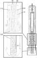
도 1a 내지 도 1c는 약물 주입 장치의 다양한 부품의 사시도이다.
도 2a 내지 도 2d는 약물 주입 장치의 다양한 상태의 사시도이다.
도 3은 플런저 막대 및 청각-촉각-시각 신호 발생 부재 조립체의 도시도이다.
도 4a 내지 도 4c는 청각-촉각-시각 신호 발생 부재 및 플런저 막대 조립체의 부품의 도시도이다.
도 5는 본 발명에 포함된 구동 수단의 사시도이다.
도 6a 내지 도 6c는 작동 중인 청각-촉각-시각 신호 발생 부재와 튜브형 하우징의 측면도이다.
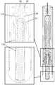
도 7 내지 도 11은 주사 과정의 다양한 상태를 도시하는, 본 발명의 일 실시예에 따른 약물 주입 장치의 종축을 따르는 측면도이다.In the following detailed description of the present invention, reference is made to the accompanying drawings.
Figures 1A-1C are perspective views of various components of a drug infusion device.
Figures 2a to 2d are perspective views of various states of the drug infusion device.
3 is an illustration of a plunger rod and auditory-tactile-visual signal generating member assembly.
Figures 4A-4C are illustrations of components of an auditory-tactile-visual signal generating member and a plunger rod assembly.
5 is a perspective view of the driving means included in the present invention.
6A-6C are side views of the active auditory-tactile-visual signal generating member and the tubular housing.
Figures 7-11 are side views along the longitudinal axis of a drug infusion device according to an embodiment of the present invention showing various states of the scanning process.
본 출원에서, "원위 부분/단부"라는 용어가 사용될 때, 이것은 환자의 약물 주입 부위로부터 가장 멀리 위치하는 주입 장치의 부분/단부 또는 그 부재들의 부분들/단부들을 지칭한다. 상응하여, "근위 부분/단부"라는 용어가 사용될 때, 이것은 환자의 약물 주입 부위에 가장 가깝게 위치하는 주입 장치의 부분/단부 또는 그 부재들의 부분들/단부들을 지칭한다.In the present application, when the term "distal portion / end portion" is used, it refers to the portion / end of the infusion device that is located furthest away from the patient's drug infusion site or portions / ends thereof. Correspondingly, when the term "proximal portion / end portion" is used, it refers to the portion / end of the infusion device that is located closest to the patient's drug injection site or portions / ends thereof.
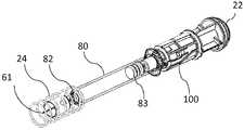
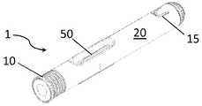
도 1a는 예시적인 약물 주입 장치(1)의 튜브형 하우징(20)의 사시도이다. 튜브형 하우징(20)은 근위 단부(11)와 대향 원위 단부(12)를 갖는다. 튜브형 하우징(20)은 그 내벽에 돌기(도시되지 않음)를 추가로 포함한다. 돌기는 튜브형 활성화 부재(30)(도 1b 참조)와 같은 활성화 수단의 리세스(36)를 수용하도록 구성된다. 튜브형 활성화 부재(30)의 리세스(36)는, 주사가 이루어진 후 튜브형 활성화 부재(30)가 그 최근위 위치에 있을 때, 튜브형 활성화 부재(30)를 튜브형 하우징(20) 내부에 로크시키기 위해 사용된다. 예시적 실시예에서는, 튜브형 하우징(20)의 내벽의 각 측부에 하나씩 두 개의 돌기가 제공되며, 상응하여 튜브형 활성화 부재(30)의 두 개의 리세스(36)가 제공된다. 튜브형 하우징(20)은, 약물 용기(80)(도 1c 참조)를 격납하기 위해 튜브형 하우징(20) 내에 동축적으로 배치되고 고정 부착되는 용기 홀더(50)를 추가로 포함한다. 약물 주사 장치(1)는, 튜브형 연장 부분(22)의 대응 레지(ledge)(23)(도 5 참조)와 결합되는 가요성 텅(15)에 의해 하우징의 원위 단부(12)에 동축적으로 배치되고 고정 부착되는 튜브형 연장 부분(22)을 추가로 포함한다.IA is a perspective view of a
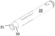
도 1b는 약물 주사 장치(1)의 튜브형 활성화 부재(30)를 도시한다. 튜브형 활성화 부재(30)는 환형 접촉 부재(31) 및 대응 제 1 공동-작용 수단(35)을 가지며, 예시적 실시예에서 제 1 공동-작용 수단은 돌기이다. 본 발명의 예시적 실시예에서는, 두 개의 대응 제 1 공동-작용 수단(35)이 제공되며, 이들은 상세히 후술하듯이 약물 주입 장치(1)를 활성화시키기 위해 사용된다. 도면에는 특히, 튜브형 활성화 부재(30)가 튜브형 하우징(20)에 대해 회전할 수도 있음을 방지하고 튜브형 활성화 부재(30)가 튜브형 하우징(20)에 대해 축방향으로 이동하도록 허용하기 위한 목적을 갖고, 튜브형 하우징(20)의 내부에서 대응 안내 막대(도시되지 않음)와 협동하도록 구성되는 안내 수단(34)이 도시되어 있다. 본 발명의 바람직한 실시예에서는, 두 개의 안내 수단(34) 및 상응하여 두 개의 안내 막대(도시되지 않음)가 제공된다. 본 발명의 일 실시예에 따르면, 예시적 실시예에서 인장 스프링인 제 2 탄성 부재(24)(도 1c 참조)는 튜브형 활성화 부재(30)의 근위 단부에 배치되어 이를 근위 방향으로 이동시킨다. 근위 바늘 단부(61)(도 1c 참조)의 본의 아닌 이용가능성을 방지하기 위해 약물 주사 장치(1)가 그 최종 위치에 위치할 때 절취부/리세스(36)는 튜브형 하우징(20)의 대응 돌기(도시되지 않음)와 결합한다.Fig. 1B shows the
도 1c는 약물 주사 장치(1)가 비활성 상태에 있을 때 환형 접촉 부재(31)가 하우징(20)의 근위 단부와 접촉하고 약물 주사 장치(1)가 활성 상태에 있을 때 환형 접촉 부재(31)가 하우징의 근위 단부로부터 소정 거리에 있도록, 튜브형 활성화 부재(30)에 대해 이를 비활성화 위치로부터 활성화 위치로 근위 방향으로 이동시키도록 배치되는 제 2 탄성 부재(24)를 추가로 포함하는 약물 주입 장치(1)의 내부를 도시한다. 약물 용기(80)는 용기 홀더(50) 내에 배치되며, 소정 체적의 약물, 슬라이드 가능한 스토퍼(83) 및 주입 부재를 갖는다. 본 발명의 예시적 실시예에서, 약물 용기(80)는 주입 부재로서 바늘(61)이 구비된 주사기이지만, 본 발명은 이것에 한정되지 않아야 하며, 다른 실시예는 주입 부재가 조정될 수 있는 멤브레인(82) 등을 갖는 약물 카트리지를 구비할 수 있다. 약물 주입 장치(1)는 튜브형 활성화 부재(30)(도 1b 참조)의 대응 제 2 공동-작용 수단(35)에 상호작용적으로 연결되는 제 2 공동-작용 수단(101)을 포함하는 튜브형 작동 부재(100)(도 5 참조), 플런저 막대(90)를 포함하는 구동 수단, 및 플런저 막대 내에 배치되는 제 1 탄성 부재(91)를 추가로 구비한다. 플런저 막대는 튜브형 연장 부분(22)의 대응 제 2 공동-작용 수단(121)(도 5 참조)에 상호작용적으로 연결되는 절취부/리세스(도 4c 참조)로서의 해제 가능한 결합 수단(94)을 포함한다. 제 1 탄성 부재(91)는 본 발명의 예시적 실시예에서 인장 스프링이다. 플런저 막대(90)의 근위 단부(92)는 슬라이드 가능한 스토퍼(83)와 접촉된다. 튜브형 작동 부재(100)(도 5 참조)는 튜브형 하우징(20)의 원위 단부에서 튜브형 연장 부분(22)의 환형 레지와 용기 홀더(50) 사이에서 튜브형 연장 부분(22)의 근위 부분 상에 회전가능하게 동축적으로 배치된다.1C shows an
튜브형 연장 부분(22)과 튜브형 작동 부재(100)는 침투 이전에 구동 수단을 사전-인장된 상태로 유지하기 위한 유지 수단을 함께 형성한다. 활성화 수단이 활성화되면, 피드백 수단은 약물이 완전히 토출되었음을 신호로 알리기 위해 유지 수단 및 구동 수단과 상호작용한다.The
도 2a 내지 도 2d는 약물 주입 장치(1)의 간소화된 사시도이며, 여기에서 도 2a는 캡(10)을 갖는 약물 주입 장치(1)의 초기 비활성 상태를 도시한다. 도 2b는 약물 주입 장치(1)의 활성 상태를 도시하며, 여기에서 캡(10)은 제거되어 있다. 도 2c는 약물 주입 장치(1)의 침투 및 주사 상태를 도시하며, 마지막으로 도 2d는 최종 로크 상태에 있는 약물 주입 장치(1)를 도시한다. 도 2a를 참조하면, 약물 주입 장치(1)는 근위 단부와 대향 원위 단부를 갖는 튜브형 하우징(20)을 포함한다. 약물 주사 장치(1)는, 튜브형 하우징(20) 내부에 슬라이드 가능하게 동축적으로 배치되고 근위 환형 접촉 부재(31)를 포함하는 튜브형 활성화 부재(30)를 추가로 포함한다. 캡(10)이 수동 조작되어 분리될 때 튜브형 활성화 부재(30)가 제 2 탄성 부재(24)(도 1c)로부터의 힘에 의해 그 비활성 위치로부터 그 활성 위치로 이동될 수 있도록, 캡(10)은 튜브형 활성화 부재(30)의 환형 접촉 부재(31)의 근위 단부면과 맞닿는 원위 단부면을 갖는다.Figures 2a to 2d are simplified perspective views of the
도 2b는 사용할 준비가 되어 있는 약물 주입 장치(1)를 도시한다. 약물 주입, 예를 들면 주사가 막 이루어지려는 때에, 조작자는 근위 단부, 즉 환형 접촉 부재(31)를 주입 부위, 예를 들면 주사 부위에 대해 가압한다. 튜브형 활성화 부재(30)는 이후 튜브형 하우징(20)에 대해 원위 방향으로 이동되며, 주사 장치로서 약물 주입 장치를 가질 때의 상대 이동 중에 바늘(61)은 피부를 수동으로 침투한다. 튜브형 활성화 부재(30)가 튜브형 하우징(20)에 대해 그 최원위 위치에 막 도달하려는 때에, 약물 주입이 이루어진다. 활성화 위치에 있는 튜브형 활성화 부재(30)가 튜브형 하우징(20)에 대해 원위 방향에서 환형 접촉 부재(31)가 튜브형 하우징(20)의 근위 단부(11)에 근접하는 주입 상태 위치로 이동될 때 약물 주입이 자동으로 이루어진다.Figure 2b shows the
도 2c는 주입이 이루어진 때를 도시하며, 이후 사용자는 약물 주입 장치(1)를 주입 부위로부터 제거함으로써, 튜브형 활성화 부재(30)가 제 2 탄성 부재(24)에 의해 가해지는 힘에 의해 튜브형 하우징(20)에 대해 근위 방향으로 이동되게 할 수 있고, 최종 상태인 로크 상태에 도달하게 한다.2C shows the time when the injection has been performed and the user then removes the
도 2d는 그 최종 로크 상태에 있는 약물 주입 장치(1)를 도시하며, 여기에서 튜브형 활성화 부재(30)가 도시하듯이 그 최근위 위치에 있으면, 이 상태에서 튜브형 활성화 부재(30)의 근위 부분은 주입 부재(61)를 완전히 보호하고, 튜브형 활성화 부재(30)는 또한 주입 부재(61)의 본의 아닌 이용가능성을 방지하기 위해 최종 위치에서는 튜브형 활성화 부재(30)의 원위 단부에 있는 절취부/리세스(36)(도 1b 참조)에 의해 로크되어 튜브형 하우징(20)의 돌기(도시되지 않음)와 결합된다.2d shows the
도 3은 신호 발생 부재(110)와 같은 피드백 수단 및 그 실시의 다양한 양태를 도시한다(도 4a 내지 도 4c도 참조). 도 3에는 약물 주입이 이루어질 때 청각적 및/또는 촉각적 및/또는 시각적 주사 확인 신호를 발생하도록 구성된 신호 발생 부재(110)를 포함하는 발명의 일 실시예가 도시되어 있으며, 여기에서는 제 1 탄성 부재가 플런저 막대 내에 사전 인장되어 배치되고 플런저 막대가 튜브형 연장 부분에 결합되는 사전-인장된 상태로부터, 플런저 막대가 튜브형 연장 부분으로부터 완전히 해제되어 더 이상 신호 발생 부재와 접촉하지 않는 해제 상태로 구동 수단이 상태를 변경할 때 약물 주입 확인 신호가 발생된다.Figure 3 shows various aspects of feedback means and their implementation, such as signal generating member 110 (see also Figures 4A-4C). 3 shows an embodiment of the invention including a
도 4a 내지 도 4c는 본 발명의 예시적 실시예에 따른 신호 발생 부재(110)의 측면도 및 사시도를 각각 도시한다. 도시된 실시예에서, 신호 발생 부재(110)는 근위 방향으로 향하는 적어도 두 개의 세장형 아암(111) 및 튜브형 연장 부분(22) 내에 배치될 때 약물 주입 장치의 원위 방향으로 향하는 하측 부분인 원위 횡단 단부 벽(112)이 제공되는 세장형 U형 브래킷이다. 신호 발생 부재(110)는 금속, 플라스틱, 또는 이들 재료의 임의의 조합으로 제조될 수 있다.4A-4C illustrate side and perspective views, respectively, of
도 4c는 플런저 막대(90) 및 제 1 탄성 부재(91)에 대한 신호 발생 부재(110)의 부분 분해 사시도이다. 아암(111)의 상측 부분에는 U-브래킷(110)의 종축에 대해 본질적으로 반경방향 외측 방향으로 연장되는 굴곡진 지지 부재(113)가 제공된다. U-브래킷(110)은 플런저 막대(90) 및 제 1 탄성 부재(91)의 적어도 일부를 둘러싸도록 구성되며, 지지 부재(113)는 구동 수단이 사전-인장된 상태에 있을 때 튜브형 연장 부분(22)의 근위 단부 상의 환형 표면 상에 얹히도록 구성되는 바, 즉 플런저 막대(90)의 개구(94)는 튜브형 연장 부분(22)의 가요성 텅(121)의 반경방향 내측 돌출된 돌기(35)와 결합된다.4C is a partially exploded perspective view of the
구동 수단이 사전-인장된 상태에 있을 때 U-브래킷(110)의 원위 단부는 상기 튜브형 연장 부분(22)의 내측 원위면으로부터 소정 거리 "D"(도 6a 참조)에 배치되며, 구동 수단이 해제된 상태에 있을 때 U-브래킷(110)의 원위 단부는 상기 튜브형 연장 부분(22)의 내측 원위면과 접촉된다. 상기 제 1 탄성 부재(91)에 의해 가해지는 잔여 힘에 의해 U-브래킷(110)의 원위 단부가 튜브형 연장 부분(22)의 내측 원위면을 가격하고 접촉할 때 청각적 및/또는 촉각적 및/또는 가시적 확인 신호가 발생된다. 이와 같이, 주입 과정 중에, 플런저 막대(90)의 원위 단부가 지지 부재(113)를 통과하면, 지지 부재(113)를 갖는 아암(111)은 해제되고 아암(111)의 사전-인장으로 인해 반경방향 내측 방향으로 이동하여 U-브래킷(110)이 원위 방향으로 이동되게 할 수 있으며, U-브래킷(110)이 튜브형 연장 부분(22)의 원위 단부를 가격할 때 신호, 통상적으로 청각적 사운드 및/또는 시각적 신호 및/또는 촉각적 신호가 발생된다. 주사-이전(pre-injection) 상태에서 U-브래킷(110)은 아암(111)이 플런저 막대(90)와 이 플런저 막대(90)를 둘러싸는 튜브형 연장 부분(22) 사이에서 플런저 막대(90)를 따르는 공간 내에 배치되도록 배치된다. 지지 부재(113)는, 플런저 막대(90)가 아암들(111) 사이로부터 멀리 이동하기 전에 신호 발생 부재(110)가 해제되지 않도록 보장하기 위해 플런저 막대(90)와 튜브형 연장 부분(22)의 내벽 사이의 공간의 반경방향 치수를 초과하는 반경방향 외측 방향으로의 치수를 가져야 한다. 원위 횡단 단부 벽(112)의 외측 원위면은 개구, 통상적으로 튜브형 연장 부분(22)의 원위 단부 벽의 관통 구멍(도시되지 않음)을 통해서 안내되도록 구성된 돌기(도시되지 않음)를 추가로 가질 수 있으며, 상기 튜브형 연장 부분(22)의 외표면 위에서 소정 거리를 원위로 연장된다. 본 발명의 예시적 실시예에서, 원위 연장 돌기는 시각적 신호를 발생하기 위해 장치의 잔여부와 다른 밝기 및/또는 색상을 갖는다. 이와 같이, 상기 돌기는 U-브래킷(110)이 튜브형 연장 부분(22)의 원위 단부를 가격할 때 촉각적 및 시각적 신호를 가능하게 할 것이다.When the drive means is in the pre-tensioned state, the distal end of the
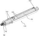
도 5는 구동 수단뿐만 아니라 유지 수단을 도시하며, 유지 수단은 튜브형 작동 부재(100) 및 튜브형 연장 부분(22)을 포함한다. 상기 제 1 대응 공동-작용 수단(35)은 튜브형 활성화 부재(30)의 내표면의 원위 단부 상의 적어도 하나의 내측 연장 돌기(도 1b 참조)이고 제 1 공동-작용 수단은 튜브형 작동 부재(100)의 외표면 상의 적어도 하나의 홈(101, 102, 103)이며, 따라서 상기 반경방향 내측 연장 돌기(35)는 적어도 하나의 홈(101, 102, 103) 내에서 안내되도록 구성되어, 튜브형 활성화 부재(30)가 축방향으로 이동될 때 튜브형 작동 부재(100)가 회전되게 한다. 플런저 막대(90)와 제 1 탄성 부재(91)를 사전-인장된 상태로 유지하기 위한 제 2 공동-작용 수단(105)은 튜브형 작동 부재(100)의 적어도 하나의 홈(105)을 포함하고 튜브형 연장 부분(22) 상의 가요성 텅(121)과 결합되며, 이는 가요성 텅(121)의 반경방향 내측 연장 돌기(35)가 플런저 막대(90)의 개구(94)와 결합됨으로써 플런저 막대(90)를 로크시킨다. 튜브형 작동 부재(100)가 회전될 때, 튜브형 작동 부재(100)의 적어도 하나의 홈(105)은 가요성 텅(121)의 반경방향 내측 연장 돌기(35)가 반경방향 연장될 수 있게 함으로써, 플런저 막대(90)의 개구(94)와 돌기(35) 사이의 결합을 해제시키며, 따라서 제 1 탄성 부재(91)의 힘에 의해 가해지는 플런저 막대(90)를 근위 방향으로 해제시킨다.Figure 5 shows the drive means as well as the retaining means, the retaining means comprising a
약물 주입 장치(1)는 튜브형 활성화 부재(30)에 상호작용적으로 연결되는 로킹 수단을 추가로 포함한다. 로킹 수단은 바람직하게 튜브형 작동 부재(100)의 환형 표면 상의 적어도 하나의 레지(106)이고 대응 제 2 공동-작용 수단은 튜브형 연장 부분(22)의 외표면 상의 적어도 하나의 돌기(95)이며, 따라서 상기 적어도 하나의 돌기(95)는 상기 적어도 하나의 레지(106)와 맞닿아서 튜브형 작동 부재(100)를 튜브형 연장 부분(22)에 회전 가능하게 고정 유지시킨다.The
도 6a 내지 도 6c는 본 발명에 따른 약물 주입 장치(1)의 원위 부분의 간소화된 측면도이다. 이들 도면의 목적은 기술되는 목적을 달성하는데 필요한 중요한 특징부를 간략히 설명하고 도시하기 위한 것이다. 도면에는 구동 수단, 즉 플런저 막대(90)와 제 1 탄성 부재(91), 및 신호 발생 부재(110)를 부분적으로 둘러싸는 튜브형 연장 부분(22)이 도시되어 있다.6A to 6C are simplified side views of a distal portion of a
도 6a에서, 약물 주입 장치(1)는 사용할 준비가 되어 있으며, 여기에서 신호 발생 부재(110)는 튜브형 연장 부분(22)의 내측 원위면으로부터 소정 거리 "D"에 있다.6A, the
도 6b에서는, 주입 과정이 시작되며, 플런저 막대(90)는 근위 방향으로 이동하여, 슬라이드 가능한 스토퍼(83)(도시되지 않음)가 주입 부재(61)를 거쳐서 약물을 토출하게 만든다. 플런저 막대(90)의 원위 단부가 신호 발생 부재(110)의 근위 부분을 통과할 때, 신호 발생 부재(110)의 아암(111)은 내측으로 굴곡되어 신호 발생 부재(110)가 원위 방향으로 이동되게 할 수 있으며, 그 결과 신호 발생 부재(110)가 튜브형 연장 부분(22)의 내측 원위면과 접촉할 때 청각적 및/또는 촉각적 신호 및/또는 시각적 신호가 발생된다. 이는 도 6c에 도시되어 있다.6B, the injection process is started and the
도 7 내지 도 11은 약물 주입 장치(1)의 종축을 따르는 측면도이다. 간명함을 위해서 신호 발생을 설명하기 위한 관련 특징부만 나타나 있으며, 약물 주입 장치(1)의 일부 주요 부분이 도 7 내지 도 11에 도시되어 있다.Figs. 7 to 11 are side views along the longitudinal axis of the
도 7은 캡(10)이 여전히 약물 주입 장치에 부착되어 있는 초기 상태에서의 약물 주입 장치를 도시한다. 용기(80)는 소정 체적의 약물을 갖는 약물 주입 장치 내에 배치되며, 이는 또한 그 원위 단부에 주입 부재(61) 및 슬라이드 가능한 스토퍼(83)를 구비한다. 제 2 탄성 부재(34)는 약물 주입 장치의 근위 단부에 배치되어 튜브 활성화 부재(30)에 근위 방향으로 힘을 가한다. 플런저 막대(90)는 슬라이드 가능한 스토퍼(83)와 접촉하는 근위 단부를 가지며, 플런저 막대(90)에 근위 방향으로 힘을 가하도록 구성되는 제 1 탄성 부재(91)를 적어도 부분적으로 둘러싼다. 플런저 막대(90)의 원위 부분은 신호 발생 부재(110)와 조합하여 튜브형 연장 부분(22)에 배치된다. 약물 주입 장치(100)의 최원위 부분에는 거리 "D", 즉 신호 발생 부재(110)의 원위 부분과 튜브형 연장 부분(22)의 내측 원위면 사이의 "사운드-발생" 거리가 도시되어 있다.Fig. 7 shows a drug infusion device in an initial state in which the
도 8은 최종 로크된 상태에 있는 약물 주입 장치를 도시하며, 여기에서 튜브형 활성화 부재(30)는 그 근위 위치에 로크되어 주입 부재(61)를 보호한다.Fig. 8 shows the drug infusion device in its final locked state, wherein the
도 9는 약물 주입 장치를 도시하며, 여기에서는 캡(10)이 약물 주입 장치로부터 제거되어 있고 그 결과 튜브형 활성화 부재(30)는 제 2 탄성 부재(24)에 의해 가해지는 힘으로 인해 전방으로 이동된다. 도면에는 신호 발생 부재(110)의 근위 부분 및 그 지지 부재(113)가 확대 도시되어 있다.9 shows a drug infusion device in which the
도 10은 약물 주입 장치를 도시하며, 여기에서는 튜브형 활성화 부재(30)가 원위 방향으로 강요되고 그 결과 플런저 막대(90)는 슬라이드 가능한 스토퍼(83)에 힘을 가할 수 있도록 해제되며 그 결과 약물이 주입된다. 도면에는 신호 발생 부재(110) 및 그 지지 부재(113)뿐만 아니라 약물 주입 장치의 최원위 부분이 확대 도시되어 있다.10 shows a drug infusion device wherein the
도 11은 주입이 이루어졌을 때의 약물 주입 장치를 도시한다. 플런저 막대(90)는 이제 슬라이드 가능한 스토퍼(83)가 용기(80)로부터 모든 약물을 주입 부재(61)를 통해서 토출하도록 강요한다. 플런저 막대(90)의 원위 부분이 신호 발생 부재(110)의 원위 부분을 통과할 때, 아암(111)은 아암의 사전-인장(상부 확대 부분으로 도시됨)으로 인해 내측으로 이동할 수 있으며, 신호 발생 부재(110)는 해제되어 원위 방향으로 이동하며 튜브형 연장 부분(22)의 원위 단부면(하부 확대 부분으로 도시됨)에 도달할 때 신호를 발생한다.11 shows a drug infusion device when infusion is made. The
이와 같이 신호 발생 부재(110)에는 두 개의 아암(111)이 제공된 것으로 도시되어 있다. 전술했듯이, 청구범위에 의해 한정되는 본 발명의 범위 내에서 더 많은 개수의 아암이 당연히 가능하다. 예를 들어 세 개 또는 네 개와 같은 더 많은 개수의 아암이 고려될 경우 이들 아암은 모두 반경방향 내측으로 향하는 힘을 발휘하도록 또한 구동 수단을 사전-인장된 상태로 확실히 유지하기 위해 신호 발생 부재(110)의 단면 평면에 균등하게 분포되도록 사전-인장되는 것이 중요하다.In this way, the
이제, 도 7 내지 도 11을 주로 참조하여, 약물 주입 장치(1)의 작동을 더 자세히 설명할 것이다. 사전-인장된 상태에서, 적어도 하나의 돌기(95)는 레지(106)와 맞닿고 있으며, 튜브형 활성화 부재(30)의 내표면에 있는 홈(105)은 가요성 텅(121)을 플런저 막대(90)로부터 해제되지 못하게 로크시키고 있다. 캡(10)이 제거되면, 약물 주입 장치(1)는 사용될 준비가 된다. 튜브형 활성화 부재(30)는 이제 그 최근위 위치에 있으며 약물 주입 장치(1)는 사용될 준비가 된다. 튜브형 활성화 부재(30)는 사용자에 의해 원위 방향으로 밀려나고 돌기(35)는 홈을 따라서 위치(101)로부터 위치(102)로 이동하여 원위 단부로부터 볼 때 튜브형 작동 부재(100)의 반시계방향 회전을 달성한다. 튜브형 작동 부재(100)의 회전 중에 돌기(95)는 레지(106)를 따라서 이동하고 마침내 레지(106)로부터 벗어나며, 따라서 사전-인장된 플런저 막대(90)는 제 1 탄성 부재(91)에 의해 가해지는 힘에 의해 근위 방향으로 이동하여 슬라이드 가능한 스토퍼(83)에 힘을 가할 수 있으며, 이로 인해 스토퍼는 근위 방향으로 이동하게 되고 이렇게 해서 약물이 주입된다. 약물이 주입되고 약물 주입 장치가 주입 부위로부터 제거되면, 튜브형 활성화 부재(30)는 반경방향 내측 연장 돌기(35)가 텅(104) 위에서 이동될 때 반경방향 내측 연장 돌기(35)를 로크시키는 튜브형 작동 부재(100)의 적어도 하나의 홈 상의 로킹 수단, 예를 들면 가요성 텅(104)(도 5 참조)과 제 2 탄성 부재(34)에 의해 근위 방향으로 가압된다. 약물 주입 장치(1)는 튜브형 활성화 부재(30)에 상호작용적으로 연결되는 로킹 수단을 추가로 포함한다. 로킹 수단은 상기 반경방향 내측 연장 돌기(35)가 텅(104) 위에서 이동될 때 반경방향 내측 연장 돌기(35)를 로크시키는 튜브형 작동 부재(100)의 적어도 하나의 홈 상의 가요성 텅(104)이다.Now, with reference mainly to Figs. 7 to 11, the operation of the
신호 발생은 다음과 같이 기능한다. 구동 수단이 사전-인장된 상태에 있을 때 U-브래킷(110)의 원위 단부는 상기 튜브형 연장 부분(22)의 내측 원위면으로부터 소정 거리 "D"(도 6a 참조)에 배치되고, 구동 수단이 해제된 상태에 있을 때 U-브래킷(110)의 원위 단부는 상기 튜브형 연장 부분(22)의 내측 원위면과 접촉한다. 상기 제 1 탄성 부재(91)에 의해 가해지는 잔여 힘에 의해 U-브래킷(110)의 원위 단부가 튜브형 연장 부분(22)의 내측 원위면을 가격하고 접촉할 때 청각적 및/또는 촉각적 및/또는 시각적 확인 신호가 발생된다. 이와 같이, 주입 과정 중에, 플런저 막대(90)의 원위 단부가 지지 부재(113)를 통과하면, 지지 부재(113)를 갖는 아암(111)은 해제되고 아암(111)의 사전-인장으로 인해 반경방향 내측 방향으로 이동하여 U-브래킷(110)이 원위 방향으로 이동되게 할 수 있으며, U-브래킷(110)이 튜브형 연장 부분(22)의 원위 단부를 가격할 때 신호, 통상적으로 청각적 사운드 및/또는 시각적 신호 및/또는 촉각적 신호가 발생된다. 주사-이전 상태에서, U-브래킷(110)은 아암(111)이 플런저 막대(90)와 이 플런저 막대(90)를 둘러싸는 튜브형 연장 부분(22) 사이에서 플런저 막대(90)를 따르는 공간 내에 배치되도록 배치된다. 지지 부재(113)는, 플런저 막대(90)가 아암들(111) 사이로부터 멀리 이동하기 전에 신호 발생 부재(110)가 해제되지 않도록 보장하기 위해 플런저 막대(90)와 튜브형 연장 부분(22)의 내벽 사이의 공간의 반경방향 치수를 초과하는 반경방향 외측 방향으로의 치수를 가져야 한다. 원위 횡단 단부 벽(112)의 외측 원위면은 개구, 통상적으로 튜브형 연장 부분(22)의 원위 단부 벽의 관통 구멍(도시되지 않음)을 통해서 안내되도록 구성된 돌기(도시되지 않음)를 추가로 가질 수 있으며, 상기 튜브형 연장 부분(22)의 외표면 위에서 소정 거리를 원위로 연장된다. 본 발명의 예시적 실시예에서, 원위 연장 돌기는 시각적 신호를 발생하기 위해 장치의 잔여부와 다른 밝기 및/또는 색상을 갖는다. 이와 같이, 상기 돌기는 U-브래킷(110)이 튜브형 연장 부분(22)의 원위 단부를 가격할 때 촉각적 및 시각적 신호를 가능하게 할 것이다.Signal generation functions as follows. When the drive means is in the pre-tensioned state, the distal end of the
그러나, 앞서 설명하고 도면에 도시되어 있는 실시예는 단지 본 발명의 비제한적 실시예로서만 간주되어야 하며 청구범위의 범위 내에서 변형될 수 있음을 알아야 한다.It should be understood, however, that the embodiments described above and illustrated in the drawings are only to be considered as non-limiting embodiments of the invention, and may be modified within the scope of the claims.
Claims (17)
Translated fromKorean약물을 토출하기 위해 약물 용기(80)에 작용하도록 구성된 구동 수단;
상기 구동 수단을 사전-인장된 상태로 유지하도록 구성된 유지 수단;
상기 유지 수단과 상호작용하여 상기 구동 수단을 사전-인장된 상태로부터 해제시키도록 구성된 활성화 수단으로서, 상기 활성화 수단은 상기 튜브형 하우징(20)에 대해 슬라이드 가능하게 동축적으로 배치되는 튜브형 활성화 부재(30)인, 상기 활성화 수단;
상기 튜브형 활성화 부재(30) 내에 동축적으로 배치되고 상기 튜브형 하우징(20)에 고정 부착되는 용기 홀더(50)로서, 상기 약물 용기(80)는 상기 용기 홀더(50) 내에 배치되고, 상기 약물 용기(80)는 소정 체적의 약물, 슬라이드 가능한 스토퍼(83) 및 주입 부재(61)를 포함하는, 상기 용기 홀더(50)를 포함하는 약물 주입 장치(1)에 있어서,
상기 구동 수단은 플런저 막대(90) 및 상기 플런저 막대 내에 사전-인장된 상태로 배치되는 제 1 탄성 부재(91)를 포함하며, 상기 플런저 막대는 약물 용기(80) 내에서 상기 슬라이드 가능한 스토퍼와 접촉하도록 배치되고;
상기 유지 수단은 튜브형 하우징(20)의 원위 단부에 고정 연결되는 튜브형 연장 부분(22), 및 튜브형 연장 부분과 튜브형 활성화 부재 양자에 상호작용적으로 연결되는 튜브형 작동 부재(100)이며, 따라서 상기 튜브형 활성화 부재가 주입 부위에 대해 가압될 때 상기 튜브형 작동 부재가 상기 튜브형 연장 부분에 대해 회전됨으로써 상기 구동 수단은 슬라이드 가능한 스토퍼(83)에 압력을 가하여 약물을 토출하기 위해 사전-인장된 상태로부터 해제되고;
상기 약물 주입 장치는 상기 유지 수단 및 상기 구동 수단 양자와 상호작용하여 약물이 완전히 토출되었음을 나타내는 청각적 및/또는 촉각적 및/또는 시각적 신호를 발생시키도록 구성된 피드백 수단을 추가로 포함하며;
상기 피드백 수단은 상기 튜브형 연장 부분 및 상기 구동 수단에 상호작용적으로 연결되는 종방향 연장되는 신호 발생 부재(110)이며, 따라서 플런저 막대가 튜브형 연장 부분 및 종방향 연장되는 신호 발생 부재로부터 완전히 해제될 때, 종방향 연장되는 신호 발생 부재는 상기 튜브형 연장 부분으로부터 해제되고 약물이 완전히 토출되었음을 나타내는 청각적 및/또는 촉각적 및/또는 시각적 신호를 발생시키기 위해 제 1 탄성 부재의 잔여 힘에 의해 원위로 변위되는 것을 특징으로 하는
약물 주입 장치.A tubular housing (20) having a proximal end (11) and an opposite distal end (12);
A driving means configured to act on the drug container (80) to dispense the drug;
Holding means configured to maintain the drive means in a pre-tensioned state;
An activation means configured to interact with said retaining means to release said drive means from said pre-tensioned state, said activation means comprising a tubular activation member (30) disposed coaxially and slidably with respect to said tubular housing ), The activation means;
Wherein the medicament container (80) is disposed in the container holder (50), the medicament container (50) being coaxially disposed within the tubular activation member (30) and fixedly attached to the tubular housing (80) is a drug injection device (1) comprising the container holder (50) including a predetermined volume of drug, a slidable stopper (83) and an injection member (61)
The drive means includes a plunger rod (90) and a first resilient member (91) that is pre-tensioned within the plunger rod, wherein the plunger rod is in contact with the slidable stopper within the drug container ;
The retaining means is a tubular extending portion 22 fixedly connected to the distal end of the tubular housing 20 and a tubular actuating member 100 operatively connected to both the tubular extending portion and the tubular active member, When the activating member is pressed against the injection site, the tubular actuating member is rotated with respect to the tubular extending portion, so that the driving means releases the pre-tensioned state in order to apply the pressure to the slidable stopper 83 to discharge the drug ;
Further comprising feedback means configured to interact with both the holding means and the drive means to generate an audible and / or tactile and / or visual signal indicating that the drug has been fully dispensed;
The feedback means is a longitudinally extending signal generating member (110) that is operatively connected to the tubular extension and the drive means such that the plunger rod is completely released from the tubular extension and the longitudinally extending signal generating member The longitudinally extending signal generating member is released from the tubular extension and is urged by a residual force of the first elastic member to generate an audible and / or tactile and / or visual signal indicating that the drug has been fully discharged Characterized in that it is displaced
Drug injection device.
상기 튜브형 작동 부재(100)는 튜브형 활성화 부재(30)의 대응 제 1 공동-작용 수단(35)에 상호작용적으로 연결되는 제 1 공동-작용 수단(101, 102), 및 튜브형 연장 부분(22)의 대응 제 2 공동-작용 수단(121)에 상호작용적으로 연결되는 제 2 공동-작용 수단(105)을 포함하고,
상기 플런저 막대(90)는 튜브형 연장 부분(22)의 대응 제 2 공동-작용 수단(121)에 상호작용적으로 연결되는 해제 가능한 결합 수단(94), 및 슬라이드 가능한 스토퍼(83)와 접촉하는 근위 단부 벽(122)을 포함하며,
상기 종방향 연장되는 신호 발생 부재(110)는 튜브형 연장 부분(22)의 내표면 상에 해제 가능하게 배치되고,
상기 제 1 탄성 부재(91)는 플런저 막대(90)의 근위 단부 벽과 맞닿는 제 1 단부(92) 및 신호 발생 부재(110)의 횡단 벽(112)과 맞닿는 제 2 단부(93)를 갖는 것을 특징으로 하는
약물 주입 장치.The method according to claim 1,
The tubular actuating member 100 comprises first co-acting means 101, 102 which are operatively connected to corresponding first co-operating means 35 of the tubular activating member 30, and tubular extending portions 22 Acting means (121), said second co-acting means (105) interacting with said second co-
The plunger rod 90 includes releasable engagement means 94 operatively connected to the corresponding second co-acting means 121 of the tubular extension 22, and a proximal Includes an end wall (122)
The longitudinally extending signal generating member 110 is releasably disposed on the inner surface of the tubular extension 22,
The first elastic member 91 has a first end 92 abutting the proximal end wall of the plunger rod 90 and a second end 93 abutting the transverse wall 112 of the signal generating member 110 Featured
Drug injection device.
상기 제 2 공동-작용 수단(105)은 튜브형 작동 부재(100)의 내표면 상에 홈을 구비하고, 상기 튜브형 연장 부분(22)의 대응 제 2 공동-작용 수단(121)은 반경방향 내측 돌기를 갖는 탄성 텅을 구비하는 것을 특징으로 하는
약물 주입 장치.10. The method of claim 9,
The second co-operating means (105) has a groove on the inner surface of the tubular actuating member (100), and the corresponding second co-operating means (121) of the tubular extension (22) Characterized in that it has an elastic tongue
Drug injection device.
상기 해제 가능한 결합 수단(94)은 구동 수단을 사전-인장된 상태로 유지하도록 구성된 탄성 텅(121)의 반경방향 내측 돌기에 해제 가능하게 결합되는 플런저 막대(90)의 외표면 상의 홈을 구비하는 것을 특징으로 하는
약물 주입 장치.11. The method of claim 10,
The releasable engaging means 94 comprises a groove on the outer surface of a plunger rod 90 which is releasably engaged with a radially inward projection of an elastic tongue 121 configured to hold the drive means in a pre- Characterized by
Drug injection device.
상기 제 1 공동-작용 수단(101, 102)은 튜브형 작동 부재(100)의 외표면 상에 홈을 구비하고, 상기 제 1 대응 공동-작용 수단(35)은 튜브형 활성화 부재(30)의 내표면의 원위 단부에 반경방향 내측 연장 돌기를 구비하며, 따라서 상기 반경방향 내측 연장 돌기(35)는 튜브형 작동 부재(100)의 외표면 상의 홈(101, 102) 내에서 안내되도록 구성되어 튜브형 활성화 부재(30)가 원위로 이동할 때 튜브형 작동 부재(100)가 회전되게 하며, 따라서 상기 탄성 텅(121)은 튜브형 작동 부재(100)의 내표면 상의 홈(105) 안으로 반경방향 외측으로 굴곡되고 상기 반경방향 내측 연장 돌기(35)는 구동 수단이 사전-인장된 상태로부터 해제되도록 플런저 막대(90)의 외표면 상의 홈(94)으로부터 결합 해제되는 것을 특징으로 하는
약물 주입 장치.12. The method of claim 11,
The first co-operating means (101, 102) has grooves on the outer surface of the tubular actuating member (100) and the first corresponding co-acting means (35) The radially inwardly extending projection 35 is configured to be guided in the grooves 101 and 102 on the outer surface of the tubular actuating member 100 so that the tubular actuating member The elastic tongue 121 is bent radially outward into the groove 105 on the inner surface of the tubular actuating member 100 and the radial direction The inner extension protrusion 35 is disengaged from the groove 94 on the outer surface of the plunger rod 90 so that the drive means is released from the pre-tensioned condition
Drug injection device.
상기 신호 발생 부재(110)는 반경방향 외측으로 연장되는 굴곡진 지지 부재(113)가 제공된 두 개의 종방향 연장되는 가요성 아암(111)과 횡단 벽(112)을 구비하는 세장형 U형 브래킷(110)이며,
상기 지지 부재(113)는 구동 수단이 사전-인장된 상태에 있을 때 튜브형 연장 부분(22)의 환형 근위 단부에 얹히도록 구성되는 것을 특징으로 하는
약물 주입 장치.13. The method according to any one of claims 9 to 12,
The signal generating member 110 comprises a three-piece U-shaped bracket (not shown) having two longitudinally extending flexible arms 111 and a transverse wall 112 provided with a flexed support member 113 extending radially outwardly 110)
Characterized in that the support member (113) is configured to rest on an annular proximal end of the tubular extension (22) when the drive means is in a pre-tensioned state
Drug injection device.
상기 U형 브래킷(110)의 횡단 벽(112)은 구동 수단이 사전-인장된 상태에 있을 때 상기 튜브형 연장 부분(22)의 내측 원위면으로부터 소정 거리(D)에 배치되는 것을 특징으로 하는
약물 주입 장치.14. The method of claim 13,
The transverse wall 112 of the U-shaped bracket 110 is disposed at a predetermined distance D from the inner circumferential surface of the tubular extension portion 22 when the drive means is in the pre-tensioned state
Drug injection device.
상기 플런저 막대(90)의 원위 단부가 지지 부재(113)를 통과했을 때 약물 주입이 이루어졌음을 확인하기 위한 청각적 신호가 발생되며, 따라서 지지 부재(113)를 갖는 종방향 연장 가요성 아암(111)이 해제되어 반경방향 내측 방향으로 이동할 수 있고, U형 브래킷(110)이 상기 제 1 탄성 부재(91)에 의해 가해지는 잔여 힘에 의해 원위 방향으로 소정 거리(D) 이동되게 할 수 있으며, 따라서 U형 브래킷의 횡단 벽(112)이 상기 튜브형 연장 부분(22)의 내측 원위면을 가격하는 것을 특징으로 하는
약물 주입 장치.15. The method of claim 14,
When the distal end of the plunger rod 90 passes through the support member 113, an auditory signal is generated to confirm that drug infusion has occurred, and thus a longitudinally extending flexible arm (not shown) 111 can be released and moved radially inward and the U-shaped bracket 110 can be moved a predetermined distance D in the distal direction by the residual force exerted by the first elastic member 91 , So that the transverse wall 112 of the U-shaped bracket charges the inner circumferential surface of the tubular extension portion 22
Drug injection device.
상기 U형 브래킷(110)의 횡단 벽(112)은 원위 연장 돌기를 포함하고 상기 튜브형 연장 부분(22)의 원위면은 관통 구멍을 포함하며, 따라서 U형 브래킷(110)의 횡단 벽(112)이 상기 튜브형 연장 부분(22)의 내측 원위면을 가격할 때 원위 연장 돌기는 관통 구멍을 통과하고 촉각적 신호 발생을 위해 상기 튜브형 연장 부분(22)의 외표면 위로 소정 거리를 원위로 연장되는 것을 특징으로 하는
약물 주입 장치.15. The method of claim 14,
The transverse wall 112 of the U-shaped bracket 110 includes a distal extension projection and the distal surface of the tubular extension portion 22 includes a through hole so that the transverse wall 112 of the U- When the inner circumferential surface of the tubular extension portion 22 is pronged, the distal extension protrusion extends through the through-hole and extends a predetermined distance over the outer surface of the tubular extension portion 22 for tactile signal generation Featured
Drug injection device.
상기 원위 연장 돌기는 시각적 신호를 발생시키기 위해 약물 주입 장치의 잔여부와 다른 밝기 및/또는 색상을 갖는 것을 특징으로 하는
약물 주입 장치.
17. The method of claim 16,
Characterized in that the distal extension has a different brightness and / or color from the rest of the drug infusion device to generate a visual signal
Drug injection device.
Applications Claiming Priority (5)
| Application Number | Priority Date | Filing Date | Title |
|---|---|---|---|
| US31945310P | 2010-03-31 | 2010-03-31 | |
| US61/319,453 | 2010-03-31 | ||
| SE1050307 | 2010-03-31 | ||
| SE1050307-6 | 2010-03-31 | ||
| PCT/SE2011/050326WO2011123024A1 (en) | 2010-03-31 | 2011-03-23 | Medicament delivery device comprising feedback signalling means |
Related Child Applications (4)
| Application Number | Title | Priority Date | Filing Date |
|---|---|---|---|
| KR1020127032923ADivisionKR101726020B1 (en) | 2010-03-31 | 2011-03-23 | Medicament delivery device |
| KR1020127032922ADivisionKR101725580B1 (en) | 2010-03-31 | 2011-03-23 | Medicament delivery device |
| KR1020127032921ADivisionKR101724785B1 (en) | 2010-03-31 | 2011-03-23 | Medicament delivery device |
| KR1020127032920ADivisionKR101724784B1 (en) | 2010-03-31 | 2011-03-23 | Medicament delivery device |
Publications (2)
| Publication Number | Publication Date |
|---|---|
| KR20130021378A KR20130021378A (en) | 2013-03-05 |
| KR101781241B1true KR101781241B1 (en) | 2017-10-10 |
Family
ID=44712475
Family Applications (5)
| Application Number | Title | Priority Date | Filing Date |
|---|---|---|---|
| KR1020127032923AActiveKR101726020B1 (en) | 2010-03-31 | 2011-03-23 | Medicament delivery device |
| KR1020127032922AActiveKR101725580B1 (en) | 2010-03-31 | 2011-03-23 | Medicament delivery device |
| KR1020127032921AActiveKR101724785B1 (en) | 2010-03-31 | 2011-03-23 | Medicament delivery device |
| KR1020127032920AActiveKR101724784B1 (en) | 2010-03-31 | 2011-03-23 | Medicament delivery device |
| KR1020127028493AActiveKR101781241B1 (en) | 2010-03-31 | 2011-03-23 | Medicament delivery device comprising feedback signalling means |
Family Applications Before (4)
| Application Number | Title | Priority Date | Filing Date |
|---|---|---|---|
| KR1020127032923AActiveKR101726020B1 (en) | 2010-03-31 | 2011-03-23 | Medicament delivery device |
| KR1020127032922AActiveKR101725580B1 (en) | 2010-03-31 | 2011-03-23 | Medicament delivery device |
| KR1020127032921AActiveKR101724785B1 (en) | 2010-03-31 | 2011-03-23 | Medicament delivery device |
| KR1020127032920AActiveKR101724784B1 (en) | 2010-03-31 | 2011-03-23 | Medicament delivery device |
Country Status (13)
| Country | Link |
|---|---|
| US (27) | US9199038B2 (en) |
| EP (8) | EP2583708B1 (en) |
| JP (5) | JP5269268B2 (en) |
| KR (5) | KR101726020B1 (en) |
| CN (6) | CN103071208B (en) |
| AU (1) | AU2011233733B2 (en) |
| CA (1) | CA2790466C (en) |
| DE (1) | DE202011110155U1 (en) |
| DK (5) | DK2583711T3 (en) |
| ES (1) | ES2618905T3 (en) |
| RU (1) | RU2531118C2 (en) |
| TW (5) | TWI632930B (en) |
| WO (1) | WO2011123024A1 (en) |
Families Citing this family (242)
| Publication number | Priority date | Publication date | Assignee | Title |
|---|---|---|---|---|
| WO2003068290A2 (en) | 2002-02-11 | 2003-08-21 | Antares Pharma, Inc. | Intradermal injector |
| HUE042286T2 (en) | 2005-01-24 | 2019-06-28 | Antares Pharma Inc | Needle-filled pre-filled syringe |
| WO2007131025A1 (en) | 2006-05-03 | 2007-11-15 | Antares Pharma, Inc. | Injector with adjustable dosing |
| WO2007131013A1 (en) | 2006-05-03 | 2007-11-15 | Antares Pharma, Inc. | Two-stage reconstituting injector |
| EP3636301A1 (en) | 2008-03-10 | 2020-04-15 | Antares Pharma, Inc. | Injector safety device |
| US8376993B2 (en) | 2008-08-05 | 2013-02-19 | Antares Pharma, Inc. | Multiple dosage injector |
| US12097357B2 (en) | 2008-09-15 | 2024-09-24 | West Pharma. Services IL, Ltd. | Stabilized pen injector |
| JP5732039B2 (en) | 2009-03-20 | 2015-06-10 | アンタレス・ファーマ・インコーポレーテッド | Hazardous drug injection system |
| US9233213B2 (en) | 2009-10-16 | 2016-01-12 | Janssen Biotech, Inc. | Palm activated drug delivery device |
| WO2011047298A2 (en) | 2009-10-16 | 2011-04-21 | Centocor Ortho Biotech Inc. | Palm activated drug delivery device |
| DK2536452T3 (en) | 2010-02-18 | 2019-01-02 | Sanofi Aventis Deutschland | autoinjector |
| EP2583708B1 (en)* | 2010-03-31 | 2023-02-22 | SHL Medical AG | Medicament delivery device comprising feedback signalling means |
| EP2399635A1 (en) | 2010-06-28 | 2011-12-28 | Sanofi-Aventis Deutschland GmbH | Auto-injector |
| EP2468333A1 (en) | 2010-12-21 | 2012-06-27 | Sanofi-Aventis Deutschland GmbH | Auto-injector |
| EP2468330A1 (en) | 2010-12-21 | 2012-06-27 | Sanofi-Aventis Deutschland GmbH | Auto-injector |
| USRE48593E1 (en) | 2010-12-21 | 2021-06-15 | Sanofi-Aventis Deutschland Gmbh | Auto-injector |
| EP2489387A1 (en) | 2011-02-18 | 2012-08-22 | Sanofi-Aventis Deutschland GmbH | Auto-injector |
| EP2489382A1 (en) | 2011-02-18 | 2012-08-22 | Sanofi-Aventis Deutschland GmbH | Auto-injector |
| EP2489381A1 (en) | 2011-02-18 | 2012-08-22 | Sanofi-Aventis Deutschland GmbH | Auto-injector |
| EP2489388A1 (en) | 2011-02-18 | 2012-08-22 | Sanofi-Aventis Deutschland GmbH | Auto-injector |
| EP2489386A1 (en) | 2011-02-18 | 2012-08-22 | Sanofi-Aventis Deutschland GmbH | Auto-injector |
| EP2489389A1 (en) | 2011-02-18 | 2012-08-22 | Sanofi-Aventis Deutschland GmbH | Detent mechanism |
| EP2489384A1 (en) | 2011-02-18 | 2012-08-22 | Sanofi-Aventis Deutschland GmbH | Auto-injector |
| EP2489385A1 (en) | 2011-02-18 | 2012-08-22 | Sanofi-Aventis Deutschland GmbH | Auto-injector |
| EP2489380A1 (en) | 2011-02-18 | 2012-08-22 | Sanofi-Aventis Deutschland GmbH | Injection device |
| GB2488578B (en)* | 2011-03-02 | 2017-05-24 | Owen Mumford Ltd | Injection device |
| USD794778S1 (en)* | 2011-03-23 | 2017-08-15 | Shl Group Ab | Housing for a medical injector |
| MX2013011263A (en) | 2011-03-29 | 2014-03-27 | Abbvie Inc | Improved shroud deployment in automatic injection devices. |
| US8496619B2 (en) | 2011-07-15 | 2013-07-30 | Antares Pharma, Inc. | Injection device with cammed ram assembly |
| US9220660B2 (en) | 2011-07-15 | 2015-12-29 | Antares Pharma, Inc. | Liquid-transfer adapter beveled spike |
| CH705345A2 (en)* | 2011-08-04 | 2013-02-15 | Tecpharma Licensing Ag | Injector with needle protection device. |
| EP2572741A1 (en) | 2011-09-23 | 2013-03-27 | Sanofi-Aventis Deutschland GmbH | Medicament delivery device and actuation mechanism for a drug delivery device |
| EP2583705A1 (en) | 2011-10-21 | 2013-04-24 | Sanofi-Aventis Deutschland GmbH | Indicator arrangement for an auto-injector |
| US9468722B2 (en)* | 2011-11-25 | 2016-10-18 | Shl Group Ab | Medicament delivery device |
| EP2601992A1 (en) | 2011-12-08 | 2013-06-12 | Sanofi-Aventis Deutschland GmbH | Syringe carrier |
| KR20170105136A (en)* | 2011-12-15 | 2017-09-18 | 에스에이치엘 그룹 에이비 | Auto-injection device |
| EP2606924A1 (en) | 2011-12-21 | 2013-06-26 | Sanofi-Aventis Deutschland GmbH | Autoinjector having a retracting syringe carrier |
| US9486583B2 (en) | 2012-03-06 | 2016-11-08 | Antares Pharma, Inc. | Prefilled syringe with breakaway force feature |
| JP5925343B2 (en)* | 2012-03-16 | 2016-05-25 | ケアベイ・ヨーロッパ・リミテッドCarebay Europe Limited | Drug delivery device |
| EP4186545A1 (en) | 2012-04-06 | 2023-05-31 | Antares Pharma, Inc. | Needle assisted jet injection administration of testosterone compositions |
| US9364610B2 (en) | 2012-05-07 | 2016-06-14 | Antares Pharma, Inc. | Injection device with cammed ram assembly |
| JP6257601B2 (en)* | 2012-05-31 | 2018-01-10 | ケアベイ・ヨーロッパ・リミテッドCarebay Europe Limited | Drug delivery device |
| EP2698179A1 (en) | 2012-08-14 | 2014-02-19 | Sanofi-Aventis Deutschland GmbH | Injection device |
| EP2719414A1 (en) | 2012-10-15 | 2014-04-16 | Sanofi-Aventis Deutschland GmbH | Medicament delivery device with use indicator |
| EP2722065A1 (en) | 2012-10-18 | 2014-04-23 | Sanofi-Aventis Deutschland GmbH | Auto-injector |
| FI3659647T3 (en) | 2013-02-11 | 2024-03-28 | Antares Pharma Inc | NEEDLE-ASSISTED SPRAY INJECTOR WITH REDUCED TRIGGER FORCE |
| CA2905031C (en) | 2013-03-11 | 2018-01-23 | Hans PFLAUMER | Dosage injector with pinion system |
| WO2014165136A1 (en) | 2013-03-12 | 2014-10-09 | Antares Pharma, Inc. | Constant volume prefilled syringes and kits thereof |
| DK2968783T3 (en)* | 2013-03-13 | 2021-07-12 | Sanofi Aventis Deutschland | MEDICINE DELIVERY DEVICE WITH A FEEDBACK FUNCTION |
| EP2777684A1 (en) | 2013-03-14 | 2014-09-17 | Sanofi-Aventis Deutschland GmbH | Medicament container carrier and adapter |
| NZ712147A (en)* | 2013-03-15 | 2018-04-27 | Janssen Biotech Inc | Palm activated drug delivery device |
| EP3590568A1 (en)* | 2013-03-22 | 2020-01-08 | TecPharma Licensing AG | Substance dispensing device with a signalling device |
| EP2823841A1 (en) | 2013-07-09 | 2015-01-14 | Sanofi-Aventis Deutschland GmbH | Autoinjector |
| EP2823838A1 (en) | 2013-07-09 | 2015-01-14 | Sanofi-Aventis Deutschland GmbH | Autoinjector |
| GB2516896B (en) | 2013-08-05 | 2020-08-12 | Owen Mumford Ltd | Injection devices |
| EP2923714A1 (en) | 2014-03-28 | 2015-09-30 | Sanofi-Aventis Deutschland GmbH | Autoinjector triggered by skin contact |
| CN106255522A (en)* | 2014-05-06 | 2016-12-21 | 卡贝欧洲有限公司 | There is the delivery device of the rotator keeping plunger rod |
| EP3151881B1 (en)* | 2014-06-05 | 2018-08-22 | Carebay Europe Ltd. | Medicament delivery device with delivery finish signal delay |
| EP3154611B1 (en)* | 2014-06-10 | 2020-07-08 | SHL Medical AG | Plunger segments drive mechanism for a medicament delivery device |
| FR3023170B1 (en)* | 2014-07-04 | 2016-08-19 | Aptar France Sas | Autoinjector. |
| GB2530714A (en)* | 2014-08-20 | 2016-04-06 | Owen Mumford Ltd | Injection devices |
| KR101960778B1 (en)* | 2014-09-01 | 2019-03-21 | 에스에이치엘 메디컬 아게 | Signal delaying assembly for a medicament delivery device |
| US10420892B2 (en)* | 2014-10-22 | 2019-09-24 | Shl Medical Ag | Drive mechanism for a medicament delivery device |
| KR101931459B1 (en)* | 2014-11-20 | 2018-12-20 | 케어베이 유럽 리미티드 | Medicament delivery device |
| US9415176B1 (en) | 2015-01-22 | 2016-08-16 | West Pharmaceutical Services, Inc. | Autoinjector having an end-of-dose visual indicator |
| CN107206183B (en)* | 2015-02-09 | 2020-09-01 | 艾斯曲尔医疗公司 | Drug delivery device with usage monitoring |
| US10881797B2 (en)* | 2015-04-24 | 2021-01-05 | Shl Medical Ag | Drive mechanism for an autoinjector |
| EP3285831B1 (en)* | 2015-04-24 | 2024-05-01 | SHL Medical AG | Sub-assembly of a medicament delivery device and a medicament delivery device |
| TW201711713A (en) | 2015-06-03 | 2017-04-01 | 賽諾菲阿凡提斯德意志有限公司 | Drug delivery device |
| TW201709941A (en) | 2015-06-03 | 2017-03-16 | 賽諾菲阿凡提斯德意志有限公司 | Sound indicator (2) |
| TW201707740A (en)* | 2015-06-03 | 2017-03-01 | 賽諾菲阿凡提斯德意志有限公司 | Drug delivery device |
| TW201707737A (en)* | 2015-06-03 | 2017-03-01 | 賽諾菲阿凡提斯德意志有限公司 | Drug delivery device (1) |
| TW201700117A (en) | 2015-06-03 | 2017-01-01 | 賽諾菲阿凡提斯德意志有限公司 | Syringe bracket and assembly method for autoinjector |
| TW201700118A (en) | 2015-06-03 | 2017-01-01 | 賽諾菲阿凡提斯德意志有限公司 | Drug delivery device (3) |
| TW201707744A (en)* | 2015-06-03 | 2017-03-01 | 賽諾菲阿凡提斯德意志有限公司 | Drug delivery device (2) |
| TW201709940A (en)* | 2015-06-03 | 2017-03-16 | 賽諾菲阿凡提斯德意志有限公司 | Sound indicator (1) |
| TW201707738A (en)* | 2015-06-03 | 2017-03-01 | 賽諾菲阿凡提斯德意志有限公司 | Syringe holder and autoinjector (2) |
| EP3310413B1 (en) | 2015-06-19 | 2019-02-13 | SHL Medical AG | Medicament delivery device |
| KR101653266B1 (en)* | 2015-07-23 | 2016-09-01 | (주)엠큐어 | Portable Infusing Device for Medicine |
| CN107921216B (en)* | 2015-08-19 | 2021-01-12 | 艾斯曲尔医疗公司 | Variable single dose drug delivery device |
| EP3141275A1 (en)* | 2015-09-14 | 2017-03-15 | Carebay Europe Ltd. | Medicament delivery device |
| FR3041262B1 (en) | 2015-09-22 | 2020-11-20 | Aptar France Sas | AUTOINJECTOR |
| US11087640B2 (en) | 2015-10-05 | 2021-08-10 | Shl Medical Ag | Medicament delivery training device |
| USD819200S1 (en) | 2015-11-06 | 2018-05-29 | Amgen Inc. | Autoinjector with removable cap |
| USD822198S1 (en) | 2015-12-09 | 2018-07-03 | Amgen Inc. | Autoinjector with removable autoinjector cap |
| EP3184134A1 (en) | 2015-12-21 | 2017-06-28 | Carebay Europe Ltd. | Tubular rotator for a medicament delivery device and a medicament delivery device comprising the same |
| US11040145B1 (en) | 2016-01-26 | 2021-06-22 | Shl Medical Ag | Plunger unit creating intermittent audio signals and a medicament delivery device having the unit |
| EP3207952A1 (en)* | 2016-02-16 | 2017-08-23 | Carebay Europe Ltd. | An automatic feedback mechanism and a medicament delivery device with user feedback capability |
| CH710381A2 (en) | 2016-02-25 | 2016-05-13 | Tecpharma Licensing Ag | Injection device for up-dosing and the distribution of a dose of a fluid product. |
| US20230166046A1 (en)* | 2016-02-29 | 2023-06-01 | Shl Medical Ag | Delivery device |
| US20170246395A1 (en)* | 2016-02-29 | 2017-08-31 | Shl Group Ab | Delivery Device |
| US11612700B2 (en)* | 2016-02-29 | 2023-03-28 | Shl Medical Ag | Delivery device |
| US20170246400A1 (en)* | 2016-02-29 | 2017-08-31 | Shl Group Ab | Delivery Device |
| US11065390B2 (en) | 2016-02-29 | 2021-07-20 | Shl Medical Ag | Automatic delivery device with end of injection indication device |
| EP3427244B1 (en)* | 2016-03-07 | 2020-09-09 | SHL Medical AG | Automatic injection training device |
| USD866757S1 (en)* | 2016-03-11 | 2019-11-12 | Millennium Pharmaceuticals, Inc. | Autoinjector |
| EP3225269B1 (en)* | 2016-03-31 | 2021-09-08 | Galderma S.A. | Plunger slack syringe |
| USD814022S1 (en)* | 2016-04-20 | 2018-03-27 | Amgen Inc. | Autoinjector with removable cap |
| USD819198S1 (en)* | 2016-04-28 | 2018-05-29 | Amgen Inc. | Autoinjector with removable cap |
| USD830539S1 (en) | 2016-05-02 | 2018-10-09 | Amgen Inc. | Autoinjector |
| DK3452146T3 (en)* | 2016-05-06 | 2024-05-27 | Shl Medical Ag | DRIVE UNIT FOR A MEDICATION DELIVERY DEVICE |
| CN109152883B (en)* | 2016-05-18 | 2020-12-01 | 艾斯曲尔医疗公司 | Drug delivery mechanism for drug delivery devices |
| USD827133S1 (en)* | 2016-07-08 | 2018-08-28 | Gerresheimer Regensburg Gmbh | Protective cap for a syringe device |
| WO2018010947A1 (en) | 2016-07-14 | 2018-01-18 | Carebay Europe Ltd. | Administration mechanism for a medicament delivery device |
| JP7142628B2 (en)* | 2016-08-26 | 2022-09-27 | サノフィ-アベンティス・ドイチュラント・ゲゼルシャフト・ミット・ベシュレンクテル・ハフツング | audible indicator |
| US11357924B2 (en) | 2016-10-13 | 2022-06-14 | Shl Medical Ag | Controller for a medicament delivery device |
| EP3534997A1 (en)* | 2016-11-01 | 2019-09-11 | Sanofi-Aventis Deutschland GmbH | Feedback mechanism for an injection device |
| EP3534990B1 (en)* | 2016-11-01 | 2025-03-19 | Sanofi-Aventis Deutschland GmbH | Feedback mechanism for an injection device |
| US10300209B2 (en)* | 2016-12-02 | 2019-05-28 | Shl Medical Ag | Feedback element for a medicament delivery device |
| USD827127S1 (en)* | 2016-12-14 | 2018-08-28 | Teva Pharmaceutical Industries Ltd. | Injector pen |
| USD827128S1 (en)* | 2017-03-14 | 2018-08-28 | Amgen Inc. | Handheld drug delivery device |
| USD903109S1 (en)* | 2017-04-06 | 2020-11-24 | F. Hoffmann-La Roche Ag | Auto injector |
| USD819804S1 (en)* | 2017-04-28 | 2018-06-05 | Ucb Biopharma Sprl | Injector |
| USD900312S1 (en)* | 2017-06-15 | 2020-10-27 | Verrica Pharmaceuticals, Inc. | Applicator |
| KR20240055848A (en) | 2017-06-30 | 2024-04-29 | 리제너론 파아마슈티컬스, 인크. | Auto-injector with anti-roll features |
| USD865946S1 (en)* | 2017-08-02 | 2019-11-05 | Norton Healthcare Limited | Drug delivery device |
| USD868961S1 (en) | 2017-09-13 | 2019-12-03 | Shl Medical Ag | Housing for a medical injector |
| USD860435S1 (en) | 2017-09-13 | 2019-09-17 | Janssen Pharmaceutica Nv | Intranasal drug delivery device |
| US20200009081A1 (en) | 2017-09-13 | 2020-01-09 | Janssen Pharmaceutica N.V. | Delivery Of Esketamine For The Treatment Of Depression |
| TWI678221B (en)* | 2017-09-28 | 2019-12-01 | 瑞士商瑞健醫療股份有限公司 | Drive unit |
| JP1629334S (en) | 2017-10-25 | 2019-04-15 | ||
| US11944787B2 (en) | 2017-10-30 | 2024-04-02 | Sanofi | Injector device |
| US11654246B2 (en) | 2017-11-03 | 2023-05-23 | Sanofi | Drug delivery device |
| US11583634B2 (en) | 2017-11-03 | 2023-02-21 | Sanofi | Plunger and drug delivery device |
| US11400232B2 (en) | 2017-11-03 | 2022-08-02 | Sanofi | Drug delivery device |
| EP3703786A1 (en)* | 2017-11-03 | 2020-09-09 | Sanofi | Drug delivery device with drive sub-assembly |
| EP3492124A1 (en)* | 2017-12-01 | 2019-06-05 | Sanofi | Injector device |
| TWI691346B (en)* | 2017-12-20 | 2020-04-21 | 瑞士商瑞健醫療股份有限公司 | Drug delivery device and starter for drug delivery device |
| EP3508238B1 (en) | 2018-01-04 | 2023-04-12 | SHL Medical AG | Support structure |
| US11529469B2 (en) | 2018-01-09 | 2022-12-20 | Shl Medical Ag | Support structure |
| USD890332S1 (en)* | 2018-02-08 | 2020-07-14 | Nuance Designs Of Ct, Llc | Autoinjector |
| USD909570S1 (en)* | 2018-03-13 | 2021-02-02 | Cresilon, Inc. | Delivery device for hemostatic compositions |
| CN116585565A (en) | 2018-03-13 | 2023-08-15 | 迈兰英国医疗保健有限公司 | Devices for injecting drugs |
| USD893710S1 (en)* | 2018-04-17 | 2020-08-18 | Shl Medical Ag | Medical injector with cap |
| USD908868S1 (en)* | 2018-05-16 | 2021-01-26 | Sanofi | Injection device |
| USD866751S1 (en)* | 2018-05-22 | 2019-11-12 | Sanofi | Injection device |
| CN112188907A (en) | 2018-05-24 | 2021-01-05 | 诺华股份有限公司 | Automatic drug delivery device |
| USD932006S1 (en) | 2018-11-21 | 2021-09-28 | Regeneron Pharmaceuticals, Inc. | Auto-injector cap |
| USD903856S1 (en) | 2018-06-29 | 2020-12-01 | Regeneron Pharmaceuticals, Inc. | Auto-injector |
| CN110870948B (en)* | 2018-08-31 | 2021-11-05 | 创领心律管理医疗器械(上海)有限公司 | Delivery device, cardiac pacing device and fixing structure thereof |
| GB2577549B (en) | 2018-09-28 | 2021-08-04 | Owen Mumford Ltd | Injection device with commit feature |
| CA3112214A1 (en) | 2018-10-05 | 2020-04-09 | Amgen Inc. | Drug delivery device having dose indicator |
| WO2020143991A1 (en)* | 2019-01-11 | 2020-07-16 | Shl Medical Ag | Medicament delivery device |
| USD915584S1 (en)* | 2019-07-15 | 2021-04-06 | Boehringer Ingelheim International Gmbh | Injection pen casing |
| EP3999149A1 (en)* | 2019-07-18 | 2022-05-25 | SHL Medical AG | Support structure, medicament delivery device and method of assemblying |
| CN110292683B (en)* | 2019-07-31 | 2023-09-22 | 派格生物医药(苏州)有限公司 | Automatic injection pen with passive trigger |
| USD1010811S1 (en) | 2019-09-30 | 2024-01-09 | Amgen Inc. | Handheld drug delivery device |
| EP4037734A1 (en) | 2019-09-30 | 2022-08-10 | Amgen Inc. | Drug delivery device |
| JP7748364B2 (en) | 2019-09-30 | 2025-10-02 | アムジエン・インコーポレーテツド | Drug Delivery Devices |
| CN118576828A (en) | 2019-09-30 | 2024-09-03 | 美国安进公司 | Drug delivery devices |
| US20220370726A1 (en)* | 2019-11-08 | 2022-11-24 | Shl Medical Ag | Tubular rotator |
| CN110681004A (en)* | 2019-11-15 | 2020-01-14 | 苏州嘉树医疗科技有限公司 | an automatic injector |
| WO2021110344A1 (en) | 2019-12-05 | 2021-06-10 | Shl Medical Ag | Feedback mechanisms |
| USD1030040S1 (en) | 2020-01-14 | 2024-06-04 | Amgen Inc. | Handheld drug delivery device |
| USD1030041S1 (en) | 2020-01-14 | 2024-06-04 | Amgen Inc. | Handheld drug delivery device |
| EP4106847A1 (en) | 2020-02-18 | 2022-12-28 | SHL Medical AG | A medicament container support assembly |
| WO2021170263A1 (en) | 2020-02-24 | 2021-09-02 | Shl Medical Ag | Sub-assembly for medicament delivery device, and medicament delivery device comprising the sub-assembly |
| USD950383S1 (en) | 2020-02-28 | 2022-05-03 | Chubby Gorilla, Inc. | Container |
| USD956211S1 (en) | 2020-02-28 | 2022-06-28 | Amgen Inc. | Handheld drug delivery device |
| USD950382S1 (en) | 2020-02-28 | 2022-05-03 | Chubby Gorilla, Inc. | Container |
| USD951092S1 (en) | 2020-02-28 | 2022-05-10 | Chubby Gorilla, Inc. | Combined cap and tamper-evident ring |
| US20230081468A1 (en) | 2020-03-11 | 2023-03-16 | Shl Medical Ag | System for evaluating a batch of medicament delivery devices, and method |
| EP4132608A1 (en) | 2020-04-07 | 2023-02-15 | SHL Medical AG | Sub-assembly for medicament delivery device, and medicament delivery device comprising the sub-assembly |
| US20230082704A1 (en)* | 2020-05-22 | 2023-03-16 | Shl Medical Ag | Medicament delivery device with a locking mechanism |
| USD955565S1 (en)* | 2020-05-29 | 2022-06-21 | Medivena Sp. Z O.O. | Needle-based device with a safety mechanism |
| USD952835S1 (en) | 2020-07-15 | 2022-05-24 | Novo Nordisk A/S | Injector pen |
| EP4192547A1 (en) | 2020-08-07 | 2023-06-14 | Sanofi | Drive arrangement for a drug delivery device |
| WO2022029098A1 (en) | 2020-08-07 | 2022-02-10 | Sanofi | Drive assembly for a drug delivery device |
| WO2022029097A1 (en) | 2020-08-07 | 2022-02-10 | Sanofi | Arrangement for a drug delivery device |
| USD1086441S1 (en) | 2020-09-02 | 2025-07-29 | Janssen Pharmaceutica Nv | Intranasal drug delivery device |
| US20230390502A1 (en)* | 2020-10-16 | 2023-12-07 | Shandong Wego Prefills Pharmaceutical Packaging Co., Ltd | Automatic syringe |
| USD962423S1 (en) | 2020-11-05 | 2022-08-30 | Amgen Inc. | Handheld drug delivery device |
| USD974547S1 (en) | 2020-11-05 | 2023-01-03 | Amgen Inc. | Handheld drug delivery device |
| USD973866S1 (en) | 2020-11-05 | 2022-12-27 | Amgen Inc. | Handheld drug delivery device |
| CN116528929A (en)* | 2020-12-02 | 2023-08-01 | 赛诺菲 | Assembly for a drug delivery device and drug delivery device |
| JP2024501680A (en)* | 2020-12-24 | 2024-01-15 | エスエイチエル・メディカル・アーゲー | drug delivery device |
| TW202237207A (en) | 2020-12-31 | 2022-10-01 | 美商再生元醫藥公司 | Auto-injector and related methods of use |
| US20240123149A1 (en)* | 2021-03-01 | 2024-04-18 | Shl Medical Ag | Powerpack sub-assembly |
| USD985116S1 (en) | 2021-03-10 | 2023-05-02 | Amgen Inc. | Handheld drug delivery device |
| USD985117S1 (en) | 2021-03-10 | 2023-05-02 | Amgen Inc. | Handheld drug delivery device |
| USD985118S1 (en) | 2021-03-10 | 2023-05-02 | Amgen Inc. | Handheld drug delivery device |
| USD985119S1 (en) | 2021-03-30 | 2023-05-02 | Amgen Inc. | Handheld drug delivery device |
| CN113368343B (en)* | 2021-05-26 | 2022-06-10 | 宁波易舒医疗科技有限公司 | Thrust mechanism, automatic injection device applying same and use method thereof |
| TWD218560S (en) | 2021-06-23 | 2022-05-01 | 瑞士商瑞健醫療股份有限公司 | Medical injector |
| CN117715671A (en)* | 2021-08-09 | 2024-03-15 | 艾斯曲尔医疗公司 | Slider and subassembly for a medicament delivery device |
| US20240366884A1 (en) | 2021-08-13 | 2024-11-07 | Shl Medical Ag | Medicament delivery device |
| EP4419175A1 (en)* | 2021-10-19 | 2024-08-28 | SHL Medical AG | Automatic feedback mechanism for a medicament delivery device |
| EP4173656A1 (en) | 2021-10-27 | 2023-05-03 | medmix Switzerland AG | Needle guard, drug delivery device and method for manufacturing |
| USD1042803S1 (en) | 2021-12-31 | 2024-09-17 | Alvotech Hf | Autoinjector housing |
| US20250114532A1 (en)* | 2022-01-21 | 2025-04-10 | Shl Medical Ag | Sub-assembly for a medicament delivery device |
| WO2023138929A1 (en) | 2022-01-21 | 2023-07-27 | Shl Medical Ag | Feedback mechanism |
| WO2023151957A1 (en) | 2022-02-09 | 2023-08-17 | Shl Medical Ag | Rotator for a medicament delivery device |
| US20250152829A1 (en) | 2022-02-18 | 2025-05-15 | Shl Medical Ag | Sub-assembly with feedback for a medicament delivery device |
| US20250186705A1 (en) | 2022-03-14 | 2025-06-12 | Shl Medical Ag | Sub-assembly for a medicament delivery device |
| CN118843490A (en) | 2022-03-22 | 2024-10-25 | 艾斯曲尔医疗公司 | Subassembly for a medicament delivery device and corresponding assembly method |
| USD1042805S1 (en)* | 2022-05-06 | 2024-09-17 | Alvotech Hf | Autoinjector housing |
| EP4522244A1 (en) | 2022-05-12 | 2025-03-19 | SHL Medical AG | A sub-assembly for a medicament delivery device |
| USD1045609S1 (en) | 2022-05-13 | 2024-10-08 | Chubby Gorilla, Inc. | Cap for a container |
| CH719766B1 (en) | 2022-06-09 | 2024-08-15 | Biorem Ag | Self-injector |
| USD1073062S1 (en)* | 2022-09-13 | 2025-04-29 | Sensile Medical Ag | Medicine injector |
| WO2024094635A1 (en) | 2022-11-04 | 2024-05-10 | Shl Medical Ag | Medicament delivery device |
| USD1071165S1 (en)* | 2022-11-28 | 2025-04-15 | Sensile Medical Ag | Medicine injector |
| CN120344284A (en) | 2022-12-15 | 2025-07-18 | 艾斯曲尔医疗公司 | Subassemblies of drug delivery devices |
| EP4410332A1 (en)* | 2023-02-02 | 2024-08-07 | Sensile Medical AG | Medical injection device with audible feedback |
| WO2024172557A1 (en)* | 2023-02-15 | 2024-08-22 | 주식회사 비에스엘 | Automated medication injection device |
| KR102694749B1 (en)* | 2023-04-05 | 2024-08-14 | 주식회사 비에스엘 | Auto-injector |
| WO2024172555A1 (en)* | 2023-02-15 | 2024-08-22 | 주식회사 비에스엘 | Automatic drug injection device |
| KR102682086B1 (en)* | 2023-04-04 | 2024-07-05 | 주식회사 비에스엘 | Auto-injector |
| JP1750677S (en)* | 2023-03-10 | 2023-08-10 | syringe cartridge | |
| WO2024188695A1 (en) | 2023-03-14 | 2024-09-19 | Shl Medical Ag | Diameter extension device for medicament delivery device |
| WO2024188692A1 (en) | 2023-03-14 | 2024-09-19 | Shl Medical Ag | Medicament delivery device |
| WO2024188693A1 (en) | 2023-03-14 | 2024-09-19 | Shl Medical Ag | Medicament delivery device |
| WO2024188691A1 (en) | 2023-03-14 | 2024-09-19 | Shl Medical Ag | Medicament delivery device |
| KR102569300B1 (en)* | 2023-03-23 | 2023-08-22 | 주식회사 비에스엘 | Needle protection cap installation sturcture for auto-injector |
| KR102694740B1 (en)* | 2023-03-29 | 2024-08-14 | 주식회사 비에스엘 | Auto-injector |
| KR102694741B1 (en)* | 2023-03-29 | 2024-08-14 | 주식회사 비에스엘 | Auto-injector |
| KR102694753B1 (en)* | 2023-03-30 | 2024-08-14 | 주식회사 비에스엘 | Auto-injector with auditory feedback |
| KR102682090B1 (en)* | 2023-04-05 | 2024-07-05 | 주식회사 비에스엘 | Auto-injector |
| KR102682092B1 (en)* | 2023-04-05 | 2024-07-05 | 주식회사 비에스엘 | Trigger structure of auto-injector |
| KR102694739B1 (en)* | 2023-04-05 | 2024-08-14 | 주식회사 비에스엘 | Auto-injector |
| KR102542985B1 (en)* | 2023-04-10 | 2023-06-14 | 주식회사 비에스엘 | Needle protection cap installation sturcture for auto-injector |
| KR102754390B1 (en)* | 2023-04-10 | 2025-01-21 | 주식회사 비에스엘 | Auto-injector |
| KR102694738B1 (en)* | 2023-04-10 | 2024-08-14 | 주식회사 비에스엘 | Auto-injector |
| KR102694747B1 (en)* | 2023-04-11 | 2024-08-14 | 주식회사 비에스엘 | Auto-injector |
| KR102694755B1 (en)* | 2023-04-11 | 2024-08-14 | 주식회사 비에스엘 | Auto-injector |
| KR102694737B1 (en)* | 2023-04-12 | 2024-08-14 | 주식회사 비에스엘 | Auto-injector with auditory feedback |
| KR102694745B1 (en)* | 2023-04-18 | 2024-08-14 | 주식회사 비에스엘 | Auto-injector with auditory feedback |
| WO2025021934A1 (en) | 2023-07-27 | 2025-01-30 | Shl Medical Ag | Medicament delivery device |
| CN116942962B (en)* | 2023-07-28 | 2024-03-08 | 苏州森恩博医疗科技有限公司 | Automatic injection pen |
| USD1049366S1 (en) | 2023-08-08 | 2024-10-29 | Amgen Inc. | Handheld drug delivery device |
| USD1051366S1 (en)* | 2023-08-08 | 2024-11-12 | Amgen Inc. | Handheld drug delivery device |
| USD1049367S1 (en)* | 2023-08-08 | 2024-10-29 | Amgen Inc. | Handheld drug delivery device |
| JP1763361S (en)* | 2023-09-08 | 2024-02-13 | ||
| USD1050422S1 (en) | 2023-09-25 | 2024-11-05 | Amgen Inc. | Handheld drug delivery device |
| USD1051367S1 (en) | 2023-09-25 | 2024-11-12 | Amgen Inc. | Handheld drug delivery device |
| USD1049369S1 (en) | 2023-09-25 | 2024-10-29 | Amgen Inc. | Handheld drug delivery device |
| WO2025153305A1 (en)* | 2024-01-19 | 2025-07-24 | Shl Medical Ag | Medicament delivery assembly with end of delivery signaling |
| US12427266B1 (en) | 2024-03-28 | 2025-09-30 | Genzyme Corporation | Needle shroud latch for injection devices |
| US12274872B1 (en) | 2024-03-28 | 2025-04-15 | Genzyme Corporation | Collar hold detent mechanism and lock for injection devices |
| US12274871B1 (en) | 2024-03-28 | 2025-04-15 | Genzyme Corporation | Hold detent mechanism for injection devices |
| US12274875B1 (en) | 2024-03-28 | 2025-04-15 | Genzyme Corporation | Needle shroud latch for injection devices |
| US12274866B1 (en) | 2024-03-28 | 2025-04-15 | Genzyme Corporation | Rotatable collar for injection devices |
Citations (4)
| Publication number | Priority date | Publication date | Assignee | Title |
|---|---|---|---|---|
| JP2007500530A (en)* | 2003-07-31 | 2007-01-18 | エス・アイ・ディ・テクノロジーズ・リミテッド・ライアビリティ・カンパニー | Injection device |
| EP1923083A1 (en) | 2006-11-17 | 2008-05-21 | Sanofi-Aventis Deutschland GmbH | Drive mechanisms for use in drug delivery devices |
| JP2008212631A (en)* | 2006-12-13 | 2008-09-18 | Shl Medical Ab | Auto-injector |
| US20080262438A1 (en) | 2007-03-22 | 2008-10-23 | Markus Bollenbach | Injection device with a time-constant delivery signal |
Family Cites Families (89)
| Publication number | Priority date | Publication date | Assignee | Title |
|---|---|---|---|---|
| US3885562A (en)* | 1973-11-16 | 1975-05-27 | John C Lampkin | Syringe with writing surface |
| US4378015A (en)* | 1981-12-21 | 1983-03-29 | Wardlaw Stephen C | Automatic injecting syringe |
| US5391157A (en)* | 1992-10-20 | 1995-02-21 | Eli Lilly And Company | End of dose indicator |
| JP3568959B2 (en)* | 1995-03-07 | 2004-09-22 | イーライ・リリー・アンド・カンパニー | Reusable dosing device |
| US5961495A (en)* | 1998-02-20 | 1999-10-05 | Becton, Dickinson And Company | Medication delivery pen having a priming mechanism |
| DE19819409A1 (en)* | 1998-04-30 | 1999-11-11 | Schering Ag | Injection device |
| USD430293S (en)* | 1998-11-24 | 2000-08-29 | Becton Dickinson And Company | Tamper evident cap for a tip cap |
| DE29912965U1 (en) | 1999-07-24 | 1999-09-16 | Hoelzle Dieter Tech Projekte | Injection device |
| US6547764B2 (en)* | 2000-05-31 | 2003-04-15 | Novo Nordisk A/S | Double pointed injection needle |
| SE518981C2 (en)* | 2000-12-14 | 2002-12-17 | Shl Medical Ab | autoinjector |
| USD493527S1 (en)* | 2002-06-07 | 2004-07-27 | Karl Storz Gmbh & Co. Kg | Handle for medical instruments |
| JP4448448B2 (en)* | 2002-09-24 | 2010-04-07 | エス・ホー・エル・グループ・アクチボラゲット | Injection device |
| AU2003275893B2 (en) | 2002-11-25 | 2008-11-13 | Tecpharma Licensing Ag | Device for automatically injecting an active agent |
| US6805686B1 (en)* | 2003-05-06 | 2004-10-19 | Abbott Laboratories | Autoinjector with extendable needle protector shroud |
| US7725202B2 (en)* | 2003-07-24 | 2010-05-25 | General Instrument Corporation | Audio splice process for digital Ad insertion |
| US7488297B2 (en)* | 2003-07-30 | 2009-02-10 | Patrice Flaherty | Blood collecting devices |
| EP1660158B1 (en)* | 2003-07-31 | 2008-12-24 | Sid Technologies Llc | Syringe with automatically triggered safety sleeve |
| AT7347U1 (en)* | 2003-08-29 | 2005-02-25 | Pharma Consult Ges M B H & Co | DEVICE FOR THE AUTOMATIC INJECTION OF INJECTION LIQUIDS |
| DE10342059B4 (en)* | 2003-09-11 | 2007-03-01 | Tecpharma Licensing Ag | Delivery device with piercing and Ausschutinrichtung |
| DE10342058B4 (en)* | 2003-09-11 | 2007-10-25 | Tecpharma Licensing Ag | Administration device for an injectable product with a trigger safety device |
| IL157981A (en)* | 2003-09-17 | 2014-01-30 | Elcam Medical Agricultural Cooperative Ass Ltd | Auto-injector |
| DE10351594A1 (en)* | 2003-11-05 | 2005-06-16 | Tecpharma Licensing Ag | Device for the administration of an injectable product |
| US20050222539A1 (en)* | 2004-03-30 | 2005-10-06 | Pediamed Pharmaceuticals, Inc. | Automatic injection device |
| EP3470099A1 (en)* | 2004-04-29 | 2019-04-17 | AbbVie Inc. | Autoinjector with extendable needle protector shroud |
| DE102004052219A1 (en)* | 2004-10-27 | 2006-05-04 | Tecpharma Licensing Ag | Injection devices for delivering insulin with restrictor, comprises prestressed spring washer, bi/multi stable signal generating burst/place element and releasing element that emits signal with deformation |
| JP4934051B2 (en)* | 2004-11-24 | 2012-05-16 | エスホーエル メディカル アクチボラゲット | Injection device |
| CN101068586B (en)* | 2004-12-01 | 2011-05-25 | 诺和诺德公司 | injection device |
| PL1877119T3 (en)* | 2005-01-25 | 2019-03-29 | Novo Nordisk A/S | An injection device with an end of dose feedback mechanism |
| US8062252B2 (en)* | 2005-02-18 | 2011-11-22 | Becton, Dickinson And Company | Safety shield system for a syringe |
| DE102005017477A1 (en)* | 2005-02-18 | 2006-08-31 | Tecpharma Licensing Ag | Spring in or for an injection device |
| DE102006006796A1 (en)* | 2006-02-14 | 2007-08-16 | Tecpharma Licensing Ag | Overlapping display |
| FR2899482A1 (en)* | 2006-04-11 | 2007-10-12 | Becton Dickinson France Soc Pa | Automatic medicament/product injection device for patient, has safety shield coupled to housing, and provided in active state at end of needle insertion step before which product/medicament injection step is not started |
| WO2008047372A2 (en)* | 2006-10-19 | 2008-04-24 | Elcam Medical Agricultural Cooperative Association Ltd. | Automatic injection device |
| US20080228147A1 (en)* | 2007-03-15 | 2008-09-18 | Bristol-Myers Squibb Company | Injector for use with pre-filled syringes and method of assembly |
| EP2129414A1 (en)* | 2007-03-22 | 2009-12-09 | Tecpharma Licensing AG | Injection device having trigger safety devices |
| CA2683949A1 (en)* | 2007-04-18 | 2008-10-30 | Meridian Medical Technologies, Inc. | Container for an automatic injector |
| US8277412B2 (en)* | 2007-07-06 | 2012-10-02 | Shl Group Ab | One shot injector with dual springs |
| WO2009040602A1 (en)* | 2007-09-25 | 2009-04-02 | Becton Dickinson France | Autoinject0r with deactivating means moveable by a safety shield |
| DE102007053743A1 (en)* | 2007-11-12 | 2009-06-10 | Tecpharma Licensing Ag | Rotatable guide sleeve with over-tensioned spring |
| WO2009063030A1 (en)* | 2007-11-14 | 2009-05-22 | Shl Group Ab | Automatic injection device with actively triggered syringe withdrawal |
| CA2711653C (en)* | 2008-01-23 | 2016-07-05 | Novo Nordisk A/S | Device for injecting apportioned doses of liquid drug |
| GB2460398A (en)* | 2008-05-20 | 2009-12-02 | Owen Mumford Ltd | Auto-injector having a magnetic injection indicator and a needle sheath retainer |
| GB2461088B (en)* | 2008-06-19 | 2012-09-26 | Cilag Gmbh Int | Injection device |
| US8926558B2 (en)* | 2008-07-04 | 2015-01-06 | Shl Group Ab | Medicament delivery device with mixing mechanism |
| DE102008037310B4 (en)* | 2008-08-11 | 2023-11-16 | Ypsomed Ag | Automatic injection device for administering a fixed dose |
| USD626648S1 (en)* | 2008-10-29 | 2010-11-02 | Astra Tech Ab | Catheter sleeve |
| US8876783B2 (en)* | 2008-12-12 | 2014-11-04 | Shl Group Ab | Medicament delivery device |
| JP5732039B2 (en)* | 2009-03-20 | 2015-06-10 | アンタレス・ファーマ・インコーポレーテッド | Hazardous drug injection system |
| USD619244S1 (en)* | 2009-05-28 | 2010-07-06 | F. Hoffmann-La Roche Ag | Auto-injector |
| TWI393578B (en)* | 2009-07-07 | 2013-04-21 | Shl Group Ab | Injection device |
| JP5701889B2 (en)* | 2009-10-08 | 2015-04-15 | エス・ホー・エル・グループ・アクチボラゲットShl Group Ab | Drug supply device |
| US8986245B2 (en)* | 2010-02-09 | 2015-03-24 | Shl Group Ab | Medicament delivery device |
| EP2583708B1 (en)* | 2010-03-31 | 2023-02-22 | SHL Medical AG | Medicament delivery device comprising feedback signalling means |
| CN102971034B (en)* | 2010-05-20 | 2015-01-21 | Shl集团有限责任公司 | drug delivery device |
| USD651310S1 (en)* | 2010-05-28 | 2011-12-27 | Zimmer, Inc. | Inserter jaw for a prosthesis impaction and extraction tool |
| WO2011163511A1 (en)* | 2010-06-23 | 2011-12-29 | Tcb Medical Devices, Llc | Injector for auto-injection of medication and associated method of use |
| USD641469S1 (en)* | 2010-09-20 | 2011-07-12 | Adhezion Biomedical, Llc | Dispensing applicator with a ridged middle |
| USD655413S1 (en)* | 2011-02-12 | 2012-03-06 | Eca Medical Instruments | Undulated medical instrument handle |
| USD702834S1 (en)* | 2011-03-22 | 2014-04-15 | Medimop Medical Projects Ltd. | Cartridge for use in injection device |
| USD734450S1 (en)* | 2011-11-01 | 2015-07-14 | Novo Nordisk A/S | Injection device |
| USD677785S1 (en)* | 2011-11-18 | 2013-03-12 | Novartis Ag | Medicine injector |
| JP5916884B2 (en)* | 2011-12-15 | 2016-05-11 | エス・ホー・エル・グループ・アクチボラゲットShl Group Ab | Cap assembly |
| JP6017672B2 (en)* | 2012-04-10 | 2016-11-02 | ケアベイ・ヨーロッパ・リミテッドCarebay Europe Limited | Cap assembly |
| USD708317S1 (en)* | 2012-04-13 | 2014-07-01 | Becton, Dickinson And Company | Autoinjector |
| USD714932S1 (en)* | 2012-05-18 | 2014-10-07 | Radius Product Development, Inc. | Automatic injection device |
| USD690416S1 (en)* | 2012-12-12 | 2013-09-24 | Pharmajet, Inc. | Needle-free syringe |
| US11311312B2 (en)* | 2013-03-15 | 2022-04-26 | Medtronic, Inc. | Subcutaneous delivery tool |
| USD733869S1 (en)* | 2013-08-30 | 2015-07-07 | Carebay Europe Limited | Housing for a medical injector |
| USD739932S1 (en)* | 2014-03-03 | 2015-09-29 | Sanofi | Medicament injection device |
| USD773660S1 (en)* | 2014-06-04 | 2016-12-06 | Chugai Seiyaku Kabushiki Kaisha | Syringe cap |
| JP1532955S (en)* | 2014-12-03 | 2015-09-07 | ||
| USD758570S1 (en)* | 2015-01-07 | 2016-06-07 | Sanofi-Aventis Deutschland Gmbh | Autoinjector housing |
| USD758567S1 (en)* | 2015-01-07 | 2016-06-07 | Sanofi-Aventis Deutschland Gmbh | Autoinjector housing |
| USD757255S1 (en)* | 2015-01-07 | 2016-05-24 | Sanofi-Aventis Deutschland Gmbh | Autoinjector housing |
| USD758569S1 (en)* | 2015-01-07 | 2016-06-07 | Sanofi-Aventis Deutschland Gmbh | Autoinjector housing |
| EP3285831B1 (en)* | 2015-04-24 | 2024-05-01 | SHL Medical AG | Sub-assembly of a medicament delivery device and a medicament delivery device |
| USD767119S1 (en)* | 2015-04-30 | 2016-09-20 | Sanofi | Autoinjector |
| USD779663S1 (en)* | 2015-05-22 | 2017-02-21 | Eca Medical Instruments | Medical instrument handle with strike plate |
| US10639451B2 (en)* | 2015-09-25 | 2020-05-05 | Hollister Incorporated, Inc. | Applicators for gripping urinary catheters and catheter assemblies including the same |
| USD771250S1 (en)* | 2015-12-22 | 2016-11-08 | Adhezion Biomedical, Llc | Liquid dispenser with an extended tip |
| USD897840S1 (en)* | 2016-01-21 | 2020-10-06 | Pacific Vial Mfg., Inc. | Glass tip |
| USD800528S1 (en)* | 2016-07-20 | 2017-10-24 | Shukla Medical | Drive handle |
| CA178923S (en)* | 2017-06-26 | 2018-12-28 | Samsung Bioepis Co Ltd | Syringe body |
| CA178924S (en)* | 2017-06-26 | 2018-12-28 | Samsung Bioepis Co Ltd | Syringe body |
| USD877897S1 (en)* | 2017-12-29 | 2020-03-10 | Ge Healthcare Bio-Sciences Corp. | Probe sheath |
| USD903111S1 (en)* | 2018-01-15 | 2020-11-24 | Hollister Incorporated | Catheter gripping aid |
| USD915584S1 (en)* | 2019-07-15 | 2021-04-06 | Boehringer Ingelheim International Gmbh | Injection pen casing |
| USD949366S1 (en)* | 2019-10-24 | 2022-04-19 | Gangxuan Li | Massager head |
| USD940898S1 (en)* | 2020-11-09 | 2022-01-11 | Perkinelmer Health Sciences, Inc. | Sample vial gripper |
- 2011
- 2011-03-23EPEP12190522.8Apatent/EP2583708B1/enactiveActive
- 2011-03-23DEDE202011110155Upatent/DE202011110155U1/ennot_activeExpired - Lifetime
- 2011-03-23JPJP2013502526Apatent/JP5269268B2/enactiveActive
- 2011-03-23CNCN201310052236.5Apatent/CN103071208B/enactiveActive
- 2011-03-23AUAU2011233733Apatent/AU2011233733B2/enactiveActive
- 2011-03-23DKDK12190526.9Tpatent/DK2583711T3/enactive
- 2011-03-23KRKR1020127032923Apatent/KR101726020B1/enactiveActive
- 2011-03-23KRKR1020127032922Apatent/KR101725580B1/enactiveActive
- 2011-03-23EPEP11763137.4Apatent/EP2552517B1/enactiveActive
- 2011-03-23EPEP12190526.9Apatent/EP2583711B1/enactiveActive
- 2011-03-23KRKR1020127032921Apatent/KR101724785B1/enactiveActive
- 2011-03-23CACA2790466Apatent/CA2790466C/enactiveActive
- 2011-03-23EPEP24209524.8Apatent/EP4497458A3/enactivePending
- 2011-03-23EPEP12190523.6Apatent/EP2583709B1/enactiveActive
- 2011-03-23DKDK12190522.8Tpatent/DK2583708T3/enactive
- 2011-03-23CNCN201310052162.5Apatent/CN103120819B/enactiveActive
- 2011-03-23CNCN201180026407.6Apatent/CN102917738B/enactiveActive
- 2011-03-23KRKR1020127032920Apatent/KR101724784B1/enactiveActive
- 2011-03-23EPEP23173799.0Apatent/EP4233943A3/enactivePending
- 2011-03-23KRKR1020127028493Apatent/KR101781241B1/enactiveActive
- 2011-03-23DKDK11763137.4Tpatent/DK2552517T3/enactive
- 2011-03-23DKDK12190523.6Tpatent/DK2583709T3/enactive
- 2011-03-23USUS13/636,241patent/US9199038B2/enactiveActive
- 2011-03-23DKDK12190524.4Tpatent/DK2583710T3/enactive
- 2011-03-23EPEP12190524.4Apatent/EP2583710B1/enactiveActive
- 2011-03-23EPEP24209527.1Apatent/EP4494676A3/enactivePending
- 2011-03-23ESES11763137.4Tpatent/ES2618905T3/enactiveActive
- 2011-03-23CNCN201510837348.0Apatent/CN105327432B/enactiveActive
- 2011-03-23WOPCT/SE2011/050326patent/WO2011123024A1/enactiveApplication Filing
- 2011-03-23RURU2012146346/14Apatent/RU2531118C2/enactive
- 2011-03-23CNCN201310052237.XApatent/CN103120820B/enactiveActive
- 2011-03-23CNCN201310052610.1Apatent/CN103143082B/enactiveActive
- 2011-03-30TWTW103105632Apatent/TWI632930B/enactive
- 2011-03-30TWTW100110882Apatent/TWI436798B/enactive
- 2011-03-30TWTW103105631Apatent/TWI632929B/enactive
- 2011-03-30TWTW103105630Apatent/TWI595906B/enactive
- 2011-03-30TWTW103105629Apatent/TWI595905B/enactive
- 2012
- 2012-10-12USUS13/650,712patent/US8821451B2/enactiveActive
- 2012-10-12USUS13/650,703patent/US9220841B2/enactiveActive
- 2012-10-12USUS13/650,717patent/US9216251B2/enactiveActive
- 2012-10-12USUS13/650,721patent/US9713677B2/enactiveActive
- 2012-10-12USUS13/650,708patent/US9662452B2/enactiveActive
- 2013
- 2013-05-02JPJP2013096886Apatent/JP2013173007A/enactivePending
- 2013-05-02JPJP2013096882Apatent/JP5531144B2/enactiveActive
- 2013-05-02JPJP2013096879Apatent/JP5503777B2/enactiveActive
- 2013-05-02JPJP2013096873Apatent/JP5503776B2/enactiveActive
- 2015
- 2015-11-17USUS14/943,782patent/US10092704B2/enactiveActive
- 2015-11-24USUS29/546,582patent/USD794777S1/enactiveActive
- 2015-11-24USUS29/546,583patent/USD816212S1/enactiveActive
- 2015-11-24USUS14/950,392patent/US10420898B2/enactiveActive
- 2015-11-24USUS29/546,584patent/USD794178S1/enactiveActive
- 2016
- 2016-06-08USUS15/176,336patent/US10130774B2/enactiveActive
- 2017
- 2017-04-06USUS15/480,820patent/US20170209647A1/ennot_activeAbandoned
- 2017-04-19USUS29/601,118patent/USD834707S1/enactiveActive
- 2017-04-19USUS29/601,117patent/USD834706S1/enactiveActive
- 2017-04-19USUS29/601,116patent/USD821573S1/enactiveActive
- 2018
- 2018-05-31USUS15/994,381patent/US10933197B2/enactiveActive
- 2020
- 2020-02-25USUS16/800,177patent/US11291775B2/enactiveActive
- 2020-12-07USUS17/114,238patent/US11771839B2/enactiveActive
- 2020-12-07USUS17/114,241patent/US11819669B2/enactiveActive
- 2020-12-07USUS17/114,235patent/US12156993B2/enactiveActive
- 2020-12-07USUS29/761,147patent/USD969312S1/enactiveActive
- 2021
- 2021-05-18USUS17/323,382patent/US11826554B2/enactiveActive
- 2021-11-03USUS17/518,139patent/US11819671B2/enactiveActive
- 2022
- 2022-09-27USUS29/854,706patent/USD1095823S1/enactiveActive
- 2023
- 2023-07-17USUS18/222,841patent/US20230355887A1/enactivePending
- 2023-09-06USUS18/243,008patent/US20230405235A1/enactivePending
Patent Citations (4)
| Publication number | Priority date | Publication date | Assignee | Title |
|---|---|---|---|---|
| JP2007500530A (en)* | 2003-07-31 | 2007-01-18 | エス・アイ・ディ・テクノロジーズ・リミテッド・ライアビリティ・カンパニー | Injection device |
| EP1923083A1 (en) | 2006-11-17 | 2008-05-21 | Sanofi-Aventis Deutschland GmbH | Drive mechanisms for use in drug delivery devices |
| JP2008212631A (en)* | 2006-12-13 | 2008-09-18 | Shl Medical Ab | Auto-injector |
| US20080262438A1 (en) | 2007-03-22 | 2008-10-23 | Markus Bollenbach | Injection device with a time-constant delivery signal |
Also Published As
Similar Documents
| Publication | Publication Date | Title |
|---|---|---|
| KR101781241B1 (en) | Medicament delivery device comprising feedback signalling means |
Legal Events
| Date | Code | Title | Description |
|---|---|---|---|
| PA0105 | International application | Patent event date:20121030 Patent event code:PA01051R01D Comment text:International Patent Application | |
| A107 | Divisional application of patent | ||
| PA0104 | Divisional application for international application | Comment text:Divisional Application for International Patent Patent event code:PA01041R01D Patent event date:20121217 | |
| PG1501 | Laying open of application | ||
| A201 | Request for examination | ||
| PA0201 | Request for examination | Patent event code:PA02012R01D Patent event date:20160322 Comment text:Request for Examination of Application | |
| E902 | Notification of reason for refusal | ||
| PE0902 | Notice of grounds for rejection | Comment text:Notification of reason for refusal Patent event date:20170202 Patent event code:PE09021S01D | |
| E701 | Decision to grant or registration of patent right | ||
| PE0701 | Decision of registration | Patent event code:PE07011S01D Comment text:Decision to Grant Registration Patent event date:20170830 | |
| GRNT | Written decision to grant | ||
| PR0701 | Registration of establishment | Comment text:Registration of Establishment Patent event date:20170918 Patent event code:PR07011E01D | |
| PR1002 | Payment of registration fee | Payment date:20170918 End annual number:3 Start annual number:1 | |
| PG1601 | Publication of registration | ||
| PR1001 | Payment of annual fee | Payment date:20200825 Start annual number:4 End annual number:4 | |
| PR1001 | Payment of annual fee | Payment date:20210901 Start annual number:5 End annual number:5 | |
| PR1001 | Payment of annual fee | Payment date:20240823 Start annual number:8 End annual number:8 |