KR101779457B1 - Antenna device for portable terminal - Google Patents
Antenna device for portable terminalDownload PDFInfo
- Publication number
- KR101779457B1 KR101779457B1KR1020110037897AKR20110037897AKR101779457B1KR 101779457 B1KR101779457 B1KR 101779457B1KR 1020110037897 AKR1020110037897 AKR 1020110037897AKR 20110037897 AKR20110037897 AKR 20110037897AKR 101779457 B1KR101779457 B1KR 101779457B1
- Authority
- KR
- South Korea
- Prior art keywords
- slot
- antenna device
- main board
- ground plane
- radiator
- Prior art date
- Legal status (The legal status is an assumption and is not a legal conclusion. Google has not performed a legal analysis and makes no representation as to the accuracy of the status listed.)
- Active
Links
Images


Classifications
- H—ELECTRICITY
- H01—ELECTRIC ELEMENTS
- H01Q—ANTENNAS, i.e. RADIO AERIALS
- H01Q1/00—Details of, or arrangements associated with, antennas
- H01Q1/12—Supports; Mounting means
- H01Q1/22—Supports; Mounting means by structural association with other equipment or articles
- H01Q1/24—Supports; Mounting means by structural association with other equipment or articles with receiving set
- H—ELECTRICITY
- H01—ELECTRIC ELEMENTS
- H01Q—ANTENNAS, i.e. RADIO AERIALS
- H01Q5/00—Arrangements for simultaneous operation of antennas on two or more different wavebands, e.g. dual-band or multi-band arrangements
- H01Q5/30—Arrangements for providing operation on different wavebands
- H01Q5/307—Individual or coupled radiating elements, each element being fed in an unspecified way
- H01Q5/342—Individual or coupled radiating elements, each element being fed in an unspecified way for different propagation modes
- H01Q5/357—Individual or coupled radiating elements, each element being fed in an unspecified way for different propagation modes using a single feed point
- H01Q5/364—Creating multiple current paths
- H—ELECTRICITY
- H01—ELECTRIC ELEMENTS
- H01Q—ANTENNAS, i.e. RADIO AERIALS
- H01Q1/00—Details of, or arrangements associated with, antennas
- H01Q1/12—Supports; Mounting means
- H01Q1/22—Supports; Mounting means by structural association with other equipment or articles
- H01Q1/24—Supports; Mounting means by structural association with other equipment or articles with receiving set
- H01Q1/241—Supports; Mounting means by structural association with other equipment or articles with receiving set used in mobile communications, e.g. GSM
- H01Q1/242—Supports; Mounting means by structural association with other equipment or articles with receiving set used in mobile communications, e.g. GSM specially adapted for hand-held use
- H01Q1/243—Supports; Mounting means by structural association with other equipment or articles with receiving set used in mobile communications, e.g. GSM specially adapted for hand-held use with built-in antennas
- H—ELECTRICITY
- H01—ELECTRIC ELEMENTS
- H01Q—ANTENNAS, i.e. RADIO AERIALS
- H01Q1/00—Details of, or arrangements associated with, antennas
- H01Q1/44—Details of, or arrangements associated with, antennas using equipment having another main function to serve additionally as an antenna, e.g. means for giving an antenna an aesthetic aspect
- H01Q1/46—Electric supply lines or communication lines
- H—ELECTRICITY
- H01—ELECTRIC ELEMENTS
- H01Q—ANTENNAS, i.e. RADIO AERIALS
- H01Q1/00—Details of, or arrangements associated with, antennas
- H01Q1/48—Earthing means; Earth screens; Counterpoises
- H—ELECTRICITY
- H01—ELECTRIC ELEMENTS
- H01Q—ANTENNAS, i.e. RADIO AERIALS
- H01Q13/00—Waveguide horns or mouths; Slot antennas; Leaky-waveguide antennas; Equivalent structures causing radiation along the transmission path of a guided wave
- H01Q13/10—Resonant slot antennas
- H—ELECTRICITY
- H01—ELECTRIC ELEMENTS
- H01Q—ANTENNAS, i.e. RADIO AERIALS
- H01Q5/00—Arrangements for simultaneous operation of antennas on two or more different wavebands, e.g. dual-band or multi-band arrangements
- H01Q5/30—Arrangements for providing operation on different wavebands
- H01Q5/378—Combination of fed elements with parasitic elements
- H—ELECTRICITY
- H01—ELECTRIC ELEMENTS
- H01Q—ANTENNAS, i.e. RADIO AERIALS
- H01Q7/00—Loop antennas with a substantially uniform current distribution around the loop and having a directional radiation pattern in a plane perpendicular to the plane of the loop
- H—ELECTRICITY
- H01—ELECTRIC ELEMENTS
- H01Q—ANTENNAS, i.e. RADIO AERIALS
- H01Q9/00—Electrically-short antennas having dimensions not more than twice the operating wavelength and consisting of conductive active radiating elements
- H01Q9/04—Resonant antennas
- H01Q9/0407—Substantially flat resonant element parallel to ground plane, e.g. patch antenna
- H01Q9/0421—Substantially flat resonant element parallel to ground plane, e.g. patch antenna with a shorting wall or a shorting pin at one end of the element
- H—ELECTRICITY
- H01—ELECTRIC ELEMENTS
- H01Q—ANTENNAS, i.e. RADIO AERIALS
- H01Q9/00—Electrically-short antennas having dimensions not more than twice the operating wavelength and consisting of conductive active radiating elements
- H01Q9/04—Resonant antennas
- H01Q9/30—Resonant antennas with feed to end of elongated active element, e.g. unipole
- H01Q9/42—Resonant antennas with feed to end of elongated active element, e.g. unipole with folded element, the folded parts being spaced apart a small fraction of the operating wavelength
Landscapes
- Engineering & Computer Science (AREA)
- Computer Networks & Wireless Communication (AREA)
- Support Of Aerials (AREA)
- Waveguide Aerials (AREA)
Abstract
Translated fromKoreanDescription
Translated fromKorean본 발명은 휴대용 단말기의 안테나 장치에 관한 것으로서, 특히 단말기의 외관을 형성하는 케이스 프레임에 구성된 금속 테두리를 이용하여 안테나의 성능을 확보하기 위한 장치에 관한 것이다.
BACKGROUND OF THE
현재 전자 통신 산업의 발달로 말미암아 이동 통신 단말기(셀룰러폰), 전자수첩, 개인 복합 단말기 등의 상기 휴대용 단말기는 현대 사회의 필수품이 되어가면서, 빠르게 변화하는 정보 전달의 중요한 수단이 되고 있다.BACKGROUND ART [0002] Due to the development of the electronic communication industry, portable terminals such as mobile communication terminals (cellular phones), electronic notebooks, and personal complex terminals have become important means of rapidly changing information as they become essentials of modern society.
이러한 상황에서 휴대용 단말기는 점차 그 기능이 부가되고 그 크기는 경박 단소화 되고 있다. 상술한 바와 같이 휴대용 단말기가 경박 단소화 되고 있는 상황에서 제한된 공간에 여러 구성 요소들을 실장시키기 더욱 어려워지고 있다. 주지하다시피, 상기 휴대용 단말기는 통화, 인터넷 등의 통신 서비스를 위한 안테나를 구비한다. 일반적으로, 상기 안테나는 클수록 성능이 우수하다. 그러나, 제한된 공간에서 원하는 성능의 안테나를 구현하기 어려워지고 있다. 더욱이, 최근 미려함을 목적으로 하는 금속체가 단말기의 외관을 형성하는 케이스 프레임에 구성되고 있고, 이러한 금속체는 상기 안테나의 성능을 열화시키는 요인이 되고 있다.
In such a situation, the function of the portable terminal is gradually added, and the size thereof is shortened. As described above, in a situation where the portable terminal is thinned and shortened, it becomes more difficult to mount various components in a limited space. As will be appreciated, the portable terminal has an antenna for communication services such as a call or the Internet. Generally, the larger the antenna, the better the performance. However, it is becoming difficult to implement a desired performance antenna in a limited space. Furthermore, recently, a metal body for the purpose of beauty is constituted in a case frame which forms an outer appearance of a terminal, and such a metal body is a factor for deteriorating the performance of the antenna.
본 발명의 목적은 케이스 프레임에 구성되어 외관을 미려하게 하는 금속체가 안테나 성능을 열화시키지 않게 하는 휴대용 단말기의 안테나 장치를 제공하는데 있다.SUMMARY OF THE INVENTION It is an object of the present invention to provide an antenna device of a portable terminal which is formed in a case frame so as to prevent a metal body that makes the appearance of the antenna from deteriorating.
본 발명의 다른 목적은 케이스 프레임에 구성되어 외관을 미려하게 하는 금속체를 이용하여 안테나 성능을 높이기 위한 휴대용 단말기의 안테나 장치를 제공하는데 있다.
Another object of the present invention is to provide an antenna device of a portable terminal for enhancing antenna performance by using a metal body formed in a case frame to provide an appearance.
상기 과제를 해결하기 위한 견지로서, 본 발명은 휴대용 단말기의 안테나 장치에 있어서, 전류를 내보내는 급전단과 접지면을 포함하는 메인 보드와, 일단은 상기 메인 보드의 급전단과 연결되고 타단은 상기 메인 보드의 접지면과 연결되는 루프 방사체 및 단말기의 테두리를 따라 배치되고 상기 메인 보드의 접지면과 전기적으로 연결되는 금속체를 포함하는 것을 특징으로 하는 안테나 장치를 제공한다.
In order to solve the above problems, the present invention provides an antenna device for a portable terminal, comprising: a main board including a power supply terminal and a ground plane for outputting current; one end connected to a power supply end of the main board; A loop radiator connected to the ground plane, and a metal body disposed along the rim of the terminal and electrically connected to the ground plane of the main board.
본 발명에 따른 안테나 장치는 케이스 프레임에 구성되어 외관을 미려하게 하는 금속 테두리를 안테나 성능을 높일 수 있는 요소로 구현할 수 있다.
The antenna device according to the present invention can be implemented as a component of a case frame, which enhances the performance of the antenna by providing a metallic rim for enhancing the appearance of the antenna.
도 1은 본 발명의 일 실시 예에 따른 휴대용 단말기의 사시도;
도 2는 본 발명의 일 실시 예에 따른 안테나 장치의 구성을 보여주는 도면;
도 3 내지 도 6은 본 발명의 일 실시 예에 따른 안테나 장치의 사시도;
도 7은 본 발명의 일 실시 예에 따른 안테나 장치의 구성을 설명하기 도면;
도 8은 본 발명의 일 실시 예에 따른 안테나 장치의 사시도;
도 9는 도 6의 일 실시 예에 따른 안테나 장치의 안테나 성능을 보여주는 그래프 및
도 10은 도 8의 일 실시 예에 따른 안테나 장치의 안테나 성능을 보여주는 그래프.1 is a perspective view of a portable terminal according to an embodiment of the present invention;
FIG. 2 is a view illustrating a configuration of an antenna device according to an embodiment of the present invention; FIG.
3 to 6 are perspective views of an antenna device according to an embodiment of the present invention;
7 is a diagram illustrating a configuration of an antenna device according to an embodiment of the present invention;
FIG. 8 is a perspective view of an antenna device according to an embodiment of the present invention; FIG.
FIG. 9 is a graph showing the antenna performance of the antenna device according to the embodiment of FIG. 6, and FIG.
FIG. 10 is a graph showing antenna performance of the antenna device according to the embodiment of FIG. 8. FIG.
이하 첨부된 도면을 참조하여 본 발명의 동작 원리를 상세히 설명한다. 하기에서 본 발명을 설명에 있어 관련된 공지 기능 또는 구성에 대한 구체적인 설명이 본 발명의 요지를 불필요하게 흐릴 수 있다고 판단되는 경우에는 그 상세한 설명을 생략할 것이다. 그리고 후술되는 용어들은 본 발명에서의 기능을 고려하여 정의된 용어들로서 이는 사용자, 운용자의 의도 또는 관례 등에 따라 달라질 수 있다. 그러므로 그 정의는 본 명세서 전반에 걸친 내용을 토대로 내려져야 할 것이다.Hereinafter, the operation principle of the present invention will be described in detail with reference to the accompanying drawings. In the following description, well-known functions or constructions are not described in detail since they would obscure the invention in unnecessary detail. The following terms are defined in consideration of the functions of the present invention, and these may be changed according to the intention of the user, the operator, or the like. Therefore, the definition should be based on the contents throughout this specification.
본 발명은 케이스 프레임에 구성되어 외관을 미려하게 하는 금속 테두리가 안테나 성능을 열화시키지 않고 오히려 안테나 성능을 높일 수 있는 요소로 구현되는 휴대용 단말기의 안테나 장치에 관한 것이다.
The present invention relates to an antenna device of a portable terminal, which is formed in a case frame and has a metal rim that makes the appearance of the antenna be a factor that does not deteriorate antenna performance but rather enhances antenna performance.
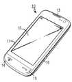
도 1은 본 발명의 일 실시 예에 따른 휴대용 단말기의 사시도이다.1 is a perspective view of a portable terminal according to an embodiment of the present invention.
도 1을 참조하면, 휴대용 단말기(10)는 외관을 형성하는 케이스 프레임(11)과, 상기 케이스 프레임(11)에 구비되는 하기 구성 요소들을 포함한다. 상기 휴대용 단말기(100)는 영상 신호를 출력하기 위한 디스플레이(12)와, 음성 신호를 출력하기 위한 스피커(13)와, 음성 신호를 입력하기 위한 마이크로폰(14) 및 입력 수단인 키버튼(15)을 구비한다. 상기 디스플레이(12)는 엘씨디(LCD;Liquid Crystal Display), 터치 스크린이 될 수 있다.Referring to FIG. 1, a
한편, 상기 케이스 프레임(11)은 외관을 미려하게 하는 금속 테두리(16)를 포함한다. 종래의 이러한 금속 테두리는 상기 메인 보드와 전자기적으로 상호작용하고, 이로 인하여 내장 안테나의 성능이 열화될 수 있다. 즉, 상기 금속 테두리는 상기 내장 안테나를 간섭한다. 차후 설명하겠지만, 이를 해결하기 위한 본 발명이 제시하는 안테나 장치는 다음과 구성을 가진다. 본 발명의 일 실시 예에 따른 안테나 장치는 상기 금속 테두리와 상기 메인 보드의 접지면을 이용하여 슬롯 방사체를 구성한다. 더욱이, 본 발명의 일 실시 예에 따른 안테나 장치는 상기 슬롯 방사체를 자기적으로 커플링시키는 루프(loop) 방사체를 포함하다. 상기 루프 방사체는 메인 보드로부터 급전되어 방사하고, 상기 슬롯 방사체는 상기 루프 방사체의 방사로 인하여 자기적으로 커플링된다. 또한, 본 발명의 일 실시 예에 따른 안테나 장치는 안테나 매칭을 위한 스터브(stub)를 더 포함할 수 있다.
On the other hand, the
도 2는 본 발명의 일 실시 예에 따른 안테나 장치의 구성을 보여주는 도면이다.2 is a view illustrating a configuration of an antenna apparatus according to an embodiment of the present invention.
도 2의 (a)를 참조하면, 본 발명의 일 실시 예에 따른 안테나 장치는 슬롯 방사체(210)와, 상기 슬롯 방사체(210)를 자기적으로 커플링시키는 루프 방사체(220)를 포함한다. 일반적인 슬롯 방사체는 넓은 금속판에 가늘고 긴 구멍, 즉, 슬롯(slot)을 가진다. 특히, 본 발명의 일 실시 예에 따른 슬롯 방사체(210)는 메인 보드(120)의 접지면(121)과 외관을 형성하는 케이스 프레임의 금속 테두리(110)가 슬롯부(123)를 사이에 두고 전기적으로 결속되어 형성된다. 상기 메인 보드(120)의 접지면(121)과 상기 금속 테두리(110)는 접촉, 솔더링(soldering) 등의 수단(122)으로 전기적으로 연결될 수 있다.Referring to FIG. 2 (a), an antenna device according to an embodiment of the present invention includes a
상기 루프 방사체(220)는 직사각형, 정사각형, 삼각형, 원형 등의 형상을 갖는 루프(loop)를 포함한다. 상기 루프의 일단(225)은 상기 메인 보드(120)의 급전라인(124)과 전기적으로 연결되고 나머지 타단(226)은 상기 메인 보드(120)의 접지면(121)과 전기적으로 연결된다. 상기 루프 방사체(220)는 상기 메인 보드(120)에 증착될 수도 있다. 일 예로, 상기 루프 방사체(220)의 방사에 따라 상기 슬롯 방사체(210)는 자기적으로 커플링되고, 첫 번째 공진과 두 번째 공진은 동시에 여기될 수 있다. 자기적으로 커플링되는 양은 상기 루프 방사체(210)의 루프 크기(H×W)와 상기 슬롯부(123)와의 이격 거리에 따라 결정됨으로, 이에 따라 안테나 매칭이 결정된다.The
도 2의 (b)를 참조하면, 본 발명의 일 실시 예에 따른 안테나 장치는 안테나 매칭을 위한 적어도 하나 이상의 스터브(230)를 더 포함할 수 있다. 상기 스터브(230)는 상기 금속 테두리(110) 또는 상기 메인 보드(120)의 접지면(121)에 부가적으로 장치되어 임피던스 정합이나 신호의 선별적인 필터링을 위한 선로를 말한다. 상기 슬롯 방사체(210) 및 루프 방사체(220)는 부정합하는 공진 주파수를 가질 수 있고 상기 스터브(230)는 이를 보정할 수 있다. 즉, 상기 스터브(230)는 기존 슬롯부(123)의 길이를 늘여 공진 길이를 확보할 수 있다. 상기 스터브(230)의 길이, 더욱 자세히 말해, 동작 주파수의 파장에 대한 스터브의 길이 비율에 따라 안테나 장치의 공진 주파수가 달라진다. 일 예로, 상기 스터브(230)의 길이를 길게 하면 공진 주파수는 감소하고, 반대로 상기 스터브(230)의 길이를 짧게 하면 공진 주파수는 증가한다.Referring to FIG. 2B, the antenna device according to an embodiment of the present invention may further include at least one
상기 메인 보드(120)는 기본 회로와 부품들을 담고 있는 기판이다. 상기 메인 보드는 상기 휴대용 단말기의 실행 환경을 설정하고 그 정보를 유지해 주고, 상기 휴대용 단말기가 안정적으로 구동되게 해주며, 상기 휴대용 단말기의 모든 장치들의 데이터 입출력 교환을 원할하게 하는 부분이다. 상기 메인 보드는 제어부, 마이크로프로세서, 보조프로세서(옵션), 메모리, 바이오스, 접속회로 등을 포함한다. 일반적으로, 상기 메인 보드(120)는 노이즈(noise) 등의 유해 요소를 줄이기 위한 상기 접지면(ground)(121)을 구비한다.
The
도 3 내지 도 6은 본 발명의 일 실시 예에 따른 안테나 장치의 사시도이다. 상기 스터브(230)는 금속 플레이트를 절곡하여 다양한 형상으로 구현될 수 있다. 도 3을 참조하면, 상기 스터브(230)는 상기 슬롯부(123)보다 수직으로 높게 위치할 수 있다. 도 4 및 5를 참조하면, 상기 스터브(230)는 적어도 하나 이상 구성될 수 있다.3 to 6 are perspective views of an antenna device according to an embodiment of the present invention. The
도 6을 참조하면, 상기 스터브(230)는 상기 슬롯부(123)보다 수직으로 높게 위치하나 단부가 상기 슬롯부(123)쪽으로 꺽여진 면(231)을 더 구성할 수 있다. 상기 꺽여진 면(231)은 상기 스터브를 용량성으로 동작시키는데 한몫할 수 있다. 일 예로, 상기 안테나 장치의 공진 주파수는 상기 꺽여진 면(231)에 의하여 낮춰질 수 있다. 도 9는 도 6의 일 실시 예에 따른 안테나 장치의 안테나 성능을 보여주는 그래프이다. 일반적으로, 반사손실(S11)이 -6dB 이하이면 신호의 송수신이 무난하다. 도 9를 참조하면, 반사 손실이 원하는 공진 주파수 1GHz와 2GHz 주변에서 -6dB이하의 값을 가져 이중 대역에서의 공진이 양호함을 보여준다.
Referring to FIG. 6, the
도 7은 본 발명의 일 실시 예에 따른 안테나 장치의 구성을 설명하기 도면이다.7 is a view for explaining a configuration of an antenna device according to an embodiment of the present invention.
도 7의 (a)는 종래의 이중대역 PIFA(Planar Inverted F Antenna) 안테나 장치의 사시도이다. 도 7의 (a)를 참조하면, 종래의 PIFA 안테나 장치는 슬롯(631)이 형성된 방사판(630)와, 상기 방사판(630)과 이격하되 상기 방사판(630)과 전기적으로 연결되는 메인 보드(620)를 포함한다. 상기 메인 보드(620)는 전류를 내보내는 급전단(624)과 접지면(621)과 연결되는 접지단(625)을 포함한다. 상기 방사판(630)은 상기 급전단(624)과 전기적으로 연결되는 급전핀(634)과, 상기 접지단(625)과 전기적으로 연결되는 접지핀(635)를 포함한다.7A is a perspective view of a conventional dual band PIFA (Planar Inverted F Antenna) antenna apparatus. Referring to FIG. 7A, a conventional PIFA antenna device includes a
도 7의 (b)는 본 발명의 일 실시 예에 따른 안테나 장치의 사시도이다. 도 7의 (b)를 참조하면, 본 발명의 일 실시 예에 따른 안테나 장치는 루프 방사체(220)로 인하여 자기적으로 커플링되는 슬롯 방사체(210)를 포함한다. 이에 대한 자세한 설명은 도 2의 (a)에서 전술하였으므로 생략하겠다.7 (b) is a perspective view of an antenna device according to an embodiment of the present invention. Referring to FIG. 7 (b), an antenna device according to an embodiment of the present invention includes a
도 7의 (c)는 본 발명의 일 실시 예에 따른 안테나 장치의 사시도이다. 도 7의 (c)에 따른 안테나 장치는 도 7의 (a) 안테나 장치와 도 7의 (b)의 안테나 장치가 통합된 구조를 가진다. 도 7의 (c)를 참조하면, 본 발명의 일 실시 예에 따른 안테나 장치는 슬롯 방사체(210), 방사판(630) 및 루프 방사체(220)를 포함한다. 상기 루프 방사체(220)는 상기 슬롯 방사체(210) 및 방사판(630)을 자기적으로 커플링시킨다. 상기 슬롯 방사체(210)는 메인 보드의 접지면(121)과 외관을 형성하는 케이스 프레임의 금속 테두리(110) 슬롯부(123)를 사이에 두고 전기적으로 결속되어 형성된다. 상기 방사판(630)은 슬롯(631)이 형성되어 있고, 상기 슬롯 방사체(210)와 수직으로 이격하되 상기 슬롯 방사체(210)의 금속 테두리(110) 또는, 메인 보드의 접지면(121)과 소정 수단(632)을 이용하여 전기적으로 연결된다. 이러한 도 7의 (c)의 안테나 장치는 광대역에서 공진할 수 있다. 일 예로, 상기 방사판(630)은 900MHz와 1800MHz에서 공진하고, 상기 슬롯 방사체(210)는 1900MHz에서 추가적으로 공진할 수 있다.
7 (c) is a perspective view of an antenna device according to an embodiment of the present invention. The antenna device of FIG. 7 (c) has a structure in which the antenna device of FIG. 7 (a) and the antenna device of FIG. 7 (b) are integrated. Referring to FIG. 7C, the antenna device according to an embodiment of the present invention includes a
도 8은 본 발명의 일 실시 예에 따른 안테나 장치의 사시도이다.8 is a perspective view of an antenna device according to an embodiment of the present invention.
도 8에 따른 안테나 장치는 도 7의 (c)에서 보여지는 안테나 장치의 구조를 가진다. 도 8을 참조하면, 본 발명의 일 실시 예에 따른 안테나 장치는 슬롯 방사체(210), 방사판(630) 및 루프 방사체(220)를 포함한다. 상기 루프 방사체(220)는 상기 슬롯 방사체(210)과 방사판(630)을 자기적으로 커플링시킨다. 상기 슬롯 방사체(210)는 메인 보드의 접지면(121)과 외관을 형성하는 케이스 프레임의 금속 테두리(110) 슬롯부(123)를 사이에 두고 전기적으로 결속되어 형성된다. 상기 방사판(630)은 슬롯(631)이 형성되어 있고, 상기 슬롯 방사체(210)와 수직으로 이격하되 상기 슬롯 방사체(210)의 금속 테두리(110)(또는, 메인 보드의 접지면(121)과 소정 수단(632)을 이용하여 전기적으로 연결된다. 특히, 상기 안테나 장치는 슬롯 방사체(210)의 기존 슬롯부(123)의 길이를 늘여 공진 길이를 확보하기 위하여 상기 슬롯부(123)에 금속 패치(240)가 추가적으로 구성할 수 있다. 상기 금속 패치(240)는 상기 슬롯 방사체(210)의 금속 테두리(110)와 전기적으로 연결되고 상기 메인 보드의 접지면(121)과 연결되지 않는다. 상기 금속 패치(240)는 상기 메인 보드에 증착될 수 있다. 또한, 상기 금속 패치(240)는 사각형, 삼각형, 원형 등의 다양한 형상이 될 수 있다. 이러한 도 8의 안테나 장치는 광대역에서 공진할 수 있다. 일 예로, 상기 방사판(630)은 1GHz와 1.8GHz에서 공진하고, 상기 금속 패치(240)로 인하여 슬롯부의 길이가 길어진 슬롯 방사체(210)는 2GHz에서 공진할 수 있다. 도 10은 도 8의 일 실시 예에 따른 안테나 장치의 안테나 성능을 보여주는 그래프이다. 도 10을 참조하면, 반사 손실(S11)이 -6dB보다 낮은 주파수 대역은 원하는 900MHz 주변과 1.7 ~ 2.2GHz 주변이다. 따라서, 본 발명의 일 실시 예에 따른 안테나 장치는 트리플 밴드 또는 쿼드 밴드를 위한 휴대용 단말기에 적용될 수 있음을 보여준다.
The antenna device according to Fig. 8 has the structure of the antenna device shown in Fig. 7 (c). Referring to FIG. 8, an antenna device according to an embodiment of the present invention includes a
한편 본 발명의 상세한 설명에서는 구체적인 실시 예에 관해 설명하였으나, 본 발명의 범위에서 벗어나지 않는 한도 내에서 여러 가지 변형이 가능하다. 그러므로 본 발명의 범위는 설명된 실시 예에 국한되어 정해져서는 아니 되며 후술하는 특허청구의 범위뿐만 아니라 이 특허청구의 범위와 균등한 것들에 의해 정해져야 한다.While the present invention has been described in connection with what is presently considered to be the most practical and preferred embodiment, it is to be understood that the invention is not limited to the disclosed embodiments. Therefore, the scope of the present invention should not be limited by the illustrated embodiments, but should be determined by the scope of the appended claims and equivalents thereof.
Claims (18)
Translated fromKorean전류를 공급하기 위한 급전단과, 접지를 위한 접지면을 포함하는 메인 보드;
상기 급전단과 전기적으로 연결되는 일단과, 상기 접지면과 전기적으로 연결되는 타단을 포함하는 루프 방사체; 및
상기 휴대용 단말기의 테두리를 따라 배치되고 상기 메인 보드의 접지면과 전기적으로 연결되는 금속체를 포함하고,
상기 접지면 및 금속체 사이의 슬롯에 의해 정의되는 슬롯 방사체가 형성되며,
상기 루프 방사체는, 상기 슬롯 안쪽에 배치되고,
상기 슬롯 방사체는, 상기 루프 방사체에 의해 전자기적으로 여기되는 안테나 장치.
1. An antenna device for a portable terminal,
A main board including a feeding end for feeding current and a ground plane for grounding;
A loop radiator including one end electrically connected to the feeding end and the other end electrically connected to the ground plane; And
And a metallic body disposed along the rim of the portable terminal and electrically connected to the ground plane of the main board,
A slot radiator defined by a slot between the ground plane and the metallic body is formed,
Wherein the loop radiator is disposed inside the slot,
Wherein the slot radiator is electromagnetically excited by the loop radiator.
상기 루프 방사체는,
상기 메인 보드의 접지면이 아닌 영역에 증착되는 안테나 장치.
The method according to claim 1,
The loop radiator includes:
And is deposited on an area other than the ground plane of the main board.
상기 금속체 또는 상기 메인 보드의 접지면과 전기적으로 연결되는 적어도 하나 이상의 스터브(stub)를 더 포함하는 안테나 장치.
The method according to claim 1,
Further comprising at least one stub electrically connected to the metal body or the ground plane of the main board.
상기 적어도 하나의 스터브는,
상기 슬롯 안쪽에 위치하거나, 상기 슬롯에 대하여 수직으로 이격되어 있는 안테나 장치.
6. The method of claim 5,
Wherein the at least one stub comprises:
And is located inside the slot or vertically spaced from the slot.
상기 적어도 하나의 스터브는,
일단으로부터 연장된 타단을 포함하는 길이를 가지는 형태이고,
상기 일단은 상기 금속체와 연결되고, 상기 타단은 어느 요소와도 연결되어 있지 않는 안테나 장치.
6. The method of claim 5,
Wherein the at least one stub comprises:
A shape having a length including the other end extending from one end,
Wherein the one end is connected to the metal body and the other end is not connected to any element.
상기 적어도 하나의 스터브는,
상기 메인 보드의 접지면이 아닌 영역에 증착되는 안테나 장치.
6. The method of claim 5,
Wherein the at least one stub comprises:
And is deposited on an area other than the ground plane of the main board.
제 2 슬롯을 포함하는 방사판을 더 포함하고,
상기 방사판은,
상기 금속체 또는 상기 메인 보드의 접지면에 전기적으로 연결되고, 상기 슬롯으로부터 수직으로 이격되어 있는 안테나 장치.
The method according to claim 1,
Further comprising a radiation plate comprising a second slot,
Wherein the radiation plate comprises:
And electrically connected to the grounded surface of the metal body or the main board, and vertically spaced from the slot.
상기 슬롯의 안쪽에 배치되는 금속 패치를 더 포함하고,
상기 금속 패치는,
상기 금속체와 전기적으로 연결되고, 상기 메인 보드의 접지면이 아닌 영역에 배치되는 안테나 장치.
The method according to claim 1,
Further comprising a metal patch disposed inside the slot,
Wherein the metal patch comprises:
And an antenna unit electrically connected to the metal body and disposed in a region other than the ground plane of the main board.
상기 금속 패치는,
사각형, 삼각형 및 원형 중 하나의 형상을 가지는 안테나 장치.
11. The method of claim 10,
Wherein the metal patch comprises:
The antenna device has a shape of one of a square, a triangle and a circle.
상기 금속체는,
상기 휴대용 단말기의 외관을 형성하는 케이스 프레임의 테두리에 폐루프 형태로 설치되는 안테나 장치.
The method according to claim 1,
Wherein the metal body comprises:
Wherein the portable terminal is installed in the shape of a closed loop on the rim of the case frame forming the external appearance of the portable terminal.
상기 안테나 장치는,
상기 루프 방사체 및 슬롯 방사체의 전자기적 커플링에 의해 850MHz, 900MHz, 1800MHz, 1900MHz 및 2100Mhz 주파수 중 적어도 하나 이상에서 공진하는 안테나 장치.
The method according to claim 1,
The antenna device includes:
900 MHz, 1800 MHz, 1900 MHz, and 2100 MHz frequency by electromagnetic coupling of the loop radiator and the slot radiator.
상기 루프 방사체는,
사각형, 삼각형 및 원형 중 하나의 형상을 가지는 안테나 장치.
The method according to claim 1,
The loop radiator includes:
The antenna device has a shape of one of a square, a triangle and a circle.
상기 슬롯은,
사각 형상인 안테나 장치.The method according to claim 1,
The slot
The antenna device has a rectangular shape.
Priority Applications (2)
| Application Number | Priority Date | Filing Date | Title |
|---|---|---|---|
| KR1020110037897AKR101779457B1 (en) | 2011-04-22 | 2011-04-22 | Antenna device for portable terminal |
| US13/440,283US8854267B2 (en) | 2011-04-22 | 2012-04-05 | Antenna device for a portable terminal |
Applications Claiming Priority (1)
| Application Number | Priority Date | Filing Date | Title |
|---|---|---|---|
| KR1020110037897AKR101779457B1 (en) | 2011-04-22 | 2011-04-22 | Antenna device for portable terminal |
Publications (2)
| Publication Number | Publication Date |
|---|---|
| KR20120119740A KR20120119740A (en) | 2012-10-31 |
| KR101779457B1true KR101779457B1 (en) | 2017-09-19 |
Family
ID=47020898
Family Applications (1)
| Application Number | Title | Priority Date | Filing Date |
|---|---|---|---|
| KR1020110037897AActiveKR101779457B1 (en) | 2011-04-22 | 2011-04-22 | Antenna device for portable terminal |
Country Status (2)
| Country | Link |
|---|---|
| US (1) | US8854267B2 (en) |
| KR (1) | KR101779457B1 (en) |
Families Citing this family (37)
| Publication number | Priority date | Publication date | Assignee | Title |
|---|---|---|---|---|
| CN103283087B (en)* | 2010-11-25 | 2016-03-16 | 诺基亚技术有限公司 | Antenna assembly and method |
| US9948126B2 (en)* | 2011-09-30 | 2018-04-17 | Samsung Electronics Co., Ltd. | Portable terminal having wireless charging module |
| KR101879705B1 (en) | 2012-01-18 | 2018-07-18 | 삼성전자주식회사 | Antenna apparatus for portable terminal |
| CN103972649B (en)* | 2013-02-04 | 2018-06-19 | 深圳富泰宏精密工业有限公司 | Antenna module and the wireless communication device with the antenna module |
| EP2772987B1 (en)* | 2013-02-27 | 2019-07-03 | Samsung Electronics Co., Ltd. | Antenna for camera |
| US9130279B1 (en)* | 2013-03-07 | 2015-09-08 | Amazon Technologies, Inc. | Multi-feed antenna with independent tuning capability |
| US9667296B2 (en)* | 2013-07-05 | 2017-05-30 | Lg Electronics Inc. | Mobile terminal having an antenna |
| GB201313312D0 (en)* | 2013-07-25 | 2013-09-11 | Bsc Associates Ltd | Multi-band antennas using loops or notches |
| US9444141B2 (en) | 2013-08-19 | 2016-09-13 | Google Technology Holdings LLC | Antenna system for a smart portable device using a continuous metal band |
| KR101544698B1 (en)* | 2013-12-23 | 2015-08-17 | 주식회사 이엠따블유 | Intenna |
| WO2015108133A1 (en) | 2014-01-20 | 2015-07-23 | 旭硝子株式会社 | Antenna directivity control system and wireless device provided with same |
| US9660326B2 (en)* | 2014-01-22 | 2017-05-23 | Galtronics Corporation, Ltd. | Conductive loop antennas |
| TWI540789B (en)* | 2014-05-16 | 2016-07-01 | 啟碁科技股份有限公司 | Wideband antenna and wireless communication device |
| CN105098351A (en)* | 2014-05-21 | 2015-11-25 | 启碁科技股份有限公司 | Broadband antenna and wireless communication device |
| WO2015182677A1 (en) | 2014-05-30 | 2015-12-03 | 旭硝子株式会社 | Multiple antenna and wireless device provided with same |
| KR20160045312A (en)* | 2014-10-17 | 2016-04-27 | 삼성전자주식회사 | Antenna device and electronic device including the same |
| KR102176367B1 (en)* | 2015-01-05 | 2020-11-09 | 엘지전자 주식회사 | Antenna module and mobile terminal having the same |
| TWI599097B (en)* | 2015-01-20 | 2017-09-11 | 啟碁科技股份有限公司 | Electronic device having antenna structure |
| US10333200B2 (en) | 2015-02-17 | 2019-06-25 | Samsung Electronics Co., Ltd. | Portable device and near field communication chip |
| US9654164B2 (en)* | 2015-04-14 | 2017-05-16 | Apple Inc. | Removable electronic device case with supplemental wireless circuitry |
| CN105762519B (en)* | 2015-04-27 | 2019-04-12 | 维沃移动通信有限公司 | A kind of slot antenna and mobile terminal |
| CN105161841B (en)* | 2015-10-12 | 2019-03-26 | 深圳市信维通信股份有限公司 | Print wireloop antenna structure |
| CN105428792A (en)* | 2015-11-12 | 2016-03-23 | 深圳市天鼎微波科技有限公司 | Complete metal frame antenna |
| CN106816680A (en)* | 2015-11-30 | 2017-06-09 | 小米科技有限责任公司 | Antenna module and electronic equipment |
| CN105846054B (en)* | 2016-01-29 | 2019-02-22 | 北京小米移动软件有限公司 | Terminal back cover and mobile terminal |
| US10103435B2 (en)* | 2016-11-09 | 2018-10-16 | Dell Products L.P. | Systems and methods for transloop impedance matching of an antenna |
| CN107359401B (en)* | 2017-06-29 | 2020-09-08 | 北京小米移动软件有限公司 | Antenna circuit, radiation generating method and device |
| GB201718009D0 (en)* | 2017-10-31 | 2017-12-13 | Smart Antenna Tech Limited | Hybrid closed slot LTE antenna |
| CN109802236B (en)* | 2017-11-17 | 2021-07-20 | 深圳富泰宏精密工业有限公司 | Antenna structure and wireless communication device with same |
| CN111628274B (en)* | 2019-02-27 | 2022-10-04 | 华为技术有限公司 | Antenna device and electronic apparatus |
| EP3916907B1 (en) | 2019-02-27 | 2025-05-21 | Huawei Technologies Co., Ltd. | Antenna apparatus and electronic device |
| JP6814254B2 (en)* | 2019-06-27 | 2021-01-13 | 日本航空電子工業株式会社 | antenna |
| TWI713254B (en)* | 2019-11-25 | 2020-12-11 | 和碩聯合科技股份有限公司 | Antenna module |
| WO2021150246A1 (en)* | 2020-01-24 | 2021-07-29 | Hewlett-Packard Development Company, L.P. | Antenna with an open slot and a closed slot |
| TWI719824B (en)* | 2020-02-06 | 2021-02-21 | 啓碁科技股份有限公司 | Antenna structure |
| CN113285212B (en)* | 2020-02-19 | 2024-05-28 | 启碁科技股份有限公司 | Antenna structure |
| TWI814438B (en)* | 2022-06-10 | 2023-09-01 | 和碩聯合科技股份有限公司 | Electronic device |
Citations (1)
| Publication number | Priority date | Publication date | Assignee | Title |
|---|---|---|---|---|
| JP2009033742A (en)* | 2007-07-04 | 2009-02-12 | Toshiba Corp | Antenna device |
Family Cites Families (4)
| Publication number | Priority date | Publication date | Assignee | Title |
|---|---|---|---|---|
| US6686886B2 (en)* | 2001-05-29 | 2004-02-03 | International Business Machines Corporation | Integrated antenna for laptop applications |
| TWI237419B (en)* | 2003-11-13 | 2005-08-01 | Hitachi Ltd | Antenna, method for manufacturing the same and portable radio terminal employing it |
| US7612725B2 (en)* | 2007-06-21 | 2009-11-03 | Apple Inc. | Antennas for handheld electronic devices with conductive bezels |
| US8542154B2 (en)* | 2009-07-02 | 2013-09-24 | Lg Electronics Inc. | Portable terminal |
- 2011
- 2011-04-22KRKR1020110037897Apatent/KR101779457B1/enactiveActive
- 2012
- 2012-04-05USUS13/440,283patent/US8854267B2/enactiveActive
Patent Citations (1)
| Publication number | Priority date | Publication date | Assignee | Title |
|---|---|---|---|---|
| JP2009033742A (en)* | 2007-07-04 | 2009-02-12 | Toshiba Corp | Antenna device |
Also Published As
| Publication number | Publication date |
|---|---|
| KR20120119740A (en) | 2012-10-31 |
| US8854267B2 (en) | 2014-10-07 |
| US20120268328A1 (en) | 2012-10-25 |
Similar Documents
| Publication | Publication Date | Title |
|---|---|---|
| KR101779457B1 (en) | Antenna device for portable terminal | |
| TWI691117B (en) | Antenna structure and wireless communication device using the same | |
| TWI646727B (en) | Mobile device | |
| US9190740B2 (en) | Communication device and antennas with high isolation characteristics | |
| TWI599095B (en) | Antenna structure and wireless communication device using the same | |
| CN103296396B (en) | Mobile device | |
| TWM553500U (en) | Mobile device | |
| CN107394351A (en) | A kind of full metal jacket mobile intelligent terminal antenna | |
| EP3288111A1 (en) | Mobile device | |
| CN108232456A (en) | Mobile device and method for manufacturing the same | |
| CN104425880A (en) | Mobile device | |
| TWI648906B (en) | Mobile device and antenna structure | |
| CN109728439A (en) | mobile device | |
| CN104466390B (en) | A kind of WiFi antennas for metal edge frame mobile phone | |
| TW201721964A (en) | Mobile device | |
| CN117458134A (en) | wearable device | |
| CN102122751B (en) | Mobile communication device | |
| TW202007008A (en) | Mobile device | |
| TWI709321B (en) | Mobile device | |
| TWI566473B (en) | Broadband antenna and portable electronic deive having same | |
| TWI663775B (en) | Antenna structure and wireless communication device with same | |
| TW201507265A (en) | Mobile device | |
| TWM654049U (en) | Antenna structure | |
| TWI669851B (en) | Mobile device | |
| CN106159414B (en) | Antenna structure |
Legal Events
| Date | Code | Title | Description |
|---|---|---|---|
| PA0109 | Patent application | St.27 status event code:A-0-1-A10-A12-nap-PA0109 | |
| R18-X000 | Changes to party contact information recorded | St.27 status event code:A-3-3-R10-R18-oth-X000 | |
| PG1501 | Laying open of application | St.27 status event code:A-1-1-Q10-Q12-nap-PG1501 | |
| A201 | Request for examination | ||
| PA0201 | Request for examination | St.27 status event code:A-1-2-D10-D11-exm-PA0201 | |
| D13-X000 | Search requested | St.27 status event code:A-1-2-D10-D13-srh-X000 | |
| D14-X000 | Search report completed | St.27 status event code:A-1-2-D10-D14-srh-X000 | |
| E902 | Notification of reason for refusal | ||
| PE0902 | Notice of grounds for rejection | St.27 status event code:A-1-2-D10-D21-exm-PE0902 | |
| E13-X000 | Pre-grant limitation requested | St.27 status event code:A-2-3-E10-E13-lim-X000 | |
| P11-X000 | Amendment of application requested | St.27 status event code:A-2-2-P10-P11-nap-X000 | |
| P13-X000 | Application amended | St.27 status event code:A-2-2-P10-P13-nap-X000 | |
| E701 | Decision to grant or registration of patent right | ||
| PE0701 | Decision of registration | St.27 status event code:A-1-2-D10-D22-exm-PE0701 | |
| GRNT | Written decision to grant | ||
| PR0701 | Registration of establishment | St.27 status event code:A-2-4-F10-F11-exm-PR0701 | |
| PR1002 | Payment of registration fee | St.27 status event code:A-2-2-U10-U11-oth-PR1002 Fee payment year number:1 | |
| PG1601 | Publication of registration | St.27 status event code:A-4-4-Q10-Q13-nap-PG1601 | |
| PR1001 | Payment of annual fee | St.27 status event code:A-4-4-U10-U11-oth-PR1001 Fee payment year number:4 | |
| PR1001 | Payment of annual fee | St.27 status event code:A-4-4-U10-U11-oth-PR1001 Fee payment year number:5 | |
| PR1001 | Payment of annual fee | St.27 status event code:A-4-4-U10-U11-oth-PR1001 Fee payment year number:6 | |
| PR1001 | Payment of annual fee | St.27 status event code:A-4-4-U10-U11-oth-PR1001 Fee payment year number:7 | |
| PR1001 | Payment of annual fee | St.27 status event code:A-4-4-U10-U11-oth-PR1001 Fee payment year number:8 | |
| PR1001 | Payment of annual fee | St.27 status event code:A-4-4-U10-U11-oth-PR1001 Fee payment year number:9 |