KR101778255B1 - Nano fiber filter and method of manufacturing the same - Google Patents
Nano fiber filter and method of manufacturing the sameDownload PDFInfo
- Publication number
- KR101778255B1 KR101778255B1KR1020150057481AKR20150057481AKR101778255B1KR 101778255 B1KR101778255 B1KR 101778255B1KR 1020150057481 AKR1020150057481 AKR 1020150057481AKR 20150057481 AKR20150057481 AKR 20150057481AKR 101778255 B1KR101778255 B1KR 101778255B1
- Authority
- KR
- South Korea
- Prior art keywords
- nozzle
- nanofibers
- nanofiber
- longitudinal direction
- solution
- Prior art date
- Legal status (The legal status is an assumption and is not a legal conclusion. Google has not performed a legal analysis and makes no representation as to the accuracy of the status listed.)
- Active
Links
Images


Classifications
- B—PERFORMING OPERATIONS; TRANSPORTING
- B01—PHYSICAL OR CHEMICAL PROCESSES OR APPARATUS IN GENERAL
- B01D—SEPARATION
- B01D39/00—Filtering material for liquid or gaseous fluids
- B01D39/14—Other self-supporting filtering material ; Other filtering material
- B01D39/16—Other self-supporting filtering material ; Other filtering material of organic material, e.g. synthetic fibres
- D—TEXTILES; PAPER
- D04—BRAIDING; LACE-MAKING; KNITTING; TRIMMINGS; NON-WOVEN FABRICS
- D04H—MAKING TEXTILE FABRICS, e.g. FROM FIBRES OR FILAMENTARY MATERIAL; FABRICS MADE BY SUCH PROCESSES OR APPARATUS, e.g. FELTS, NON-WOVEN FABRICS; COTTON-WOOL; WADDING ; NON-WOVEN FABRICS FROM STAPLE FIBRES, FILAMENTS OR YARNS, BONDED WITH AT LEAST ONE WEB-LIKE MATERIAL DURING THEIR CONSOLIDATION
- D04H1/00—Non-woven fabrics formed wholly or mainly of staple fibres or like relatively short fibres
- D04H1/40—Non-woven fabrics formed wholly or mainly of staple fibres or like relatively short fibres from fleeces or layers composed of fibres without existing or potential cohesive properties
- D04H1/42—Non-woven fabrics formed wholly or mainly of staple fibres or like relatively short fibres from fleeces or layers composed of fibres without existing or potential cohesive properties characterised by the use of certain kinds of fibres insofar as this use has no preponderant influence on the consolidation of the fleece
- D04H1/4374—Non-woven fabrics formed wholly or mainly of staple fibres or like relatively short fibres from fleeces or layers composed of fibres without existing or potential cohesive properties characterised by the use of certain kinds of fibres insofar as this use has no preponderant influence on the consolidation of the fleece using different kinds of webs, e.g. by layering webs
- D—TEXTILES; PAPER
- D04—BRAIDING; LACE-MAKING; KNITTING; TRIMMINGS; NON-WOVEN FABRICS
- D04H—MAKING TEXTILE FABRICS, e.g. FROM FIBRES OR FILAMENTARY MATERIAL; FABRICS MADE BY SUCH PROCESSES OR APPARATUS, e.g. FELTS, NON-WOVEN FABRICS; COTTON-WOOL; WADDING ; NON-WOVEN FABRICS FROM STAPLE FIBRES, FILAMENTS OR YARNS, BONDED WITH AT LEAST ONE WEB-LIKE MATERIAL DURING THEIR CONSOLIDATION
- D04H1/00—Non-woven fabrics formed wholly or mainly of staple fibres or like relatively short fibres
- D04H1/70—Non-woven fabrics formed wholly or mainly of staple fibres or like relatively short fibres characterised by the method of forming fleeces or layers, e.g. reorientation of fibres
- D04H1/72—Non-woven fabrics formed wholly or mainly of staple fibres or like relatively short fibres characterised by the method of forming fleeces or layers, e.g. reorientation of fibres the fibres being randomly arranged
- D04H1/728—Non-woven fabrics formed wholly or mainly of staple fibres or like relatively short fibres characterised by the method of forming fleeces or layers, e.g. reorientation of fibres the fibres being randomly arranged by electro-spinning
- F—MECHANICAL ENGINEERING; LIGHTING; HEATING; WEAPONS; BLASTING
- F02—COMBUSTION ENGINES; HOT-GAS OR COMBUSTION-PRODUCT ENGINE PLANTS
- F02C—GAS-TURBINE PLANTS; AIR INTAKES FOR JET-PROPULSION PLANTS; CONTROLLING FUEL SUPPLY IN AIR-BREATHING JET-PROPULSION PLANTS
- F02C7/00—Features, components parts, details or accessories, not provided for in, or of interest apart form groups F02C1/00 - F02C6/00; Air intakes for jet-propulsion plants
- F02C7/04—Air intakes for gas-turbine plants or jet-propulsion plants
- F02C7/05—Air intakes for gas-turbine plants or jet-propulsion plants having provisions for obviating the penetration of damaging objects or particles
- F02C7/052—Air intakes for gas-turbine plants or jet-propulsion plants having provisions for obviating the penetration of damaging objects or particles with dust-separation devices
Landscapes
- Engineering & Computer Science (AREA)
- Chemical & Material Sciences (AREA)
- Combustion & Propulsion (AREA)
- Textile Engineering (AREA)
- Chemical Kinetics & Catalysis (AREA)
- Mechanical Engineering (AREA)
- General Engineering & Computer Science (AREA)
- Spinning Methods And Devices For Manufacturing Artificial Fibers (AREA)
- Nonwoven Fabrics (AREA)
Abstract
Translated fromKoreanDescription
Translated fromKorean본 발명은 평명방향으로 평량이 상이한 나노섬유필터의 제조방법에 관한 것으로서, 보다 상세하게는 길이 방향(MD)으로 평량이 상이한 나노섬유필터의 제조방법 및 이에 의해 제조된 나노섬유필터 관한 것이다.The present invention relates to a method of manufacturing a nanofiber filter having different basis weights in a planar direction, and more particularly, to a method of manufacturing a nanofiber filter having different basis weights in the longitudinal direction (MD) and a nanofiber filter manufactured thereby.
일반적으로, 나노섬유(Nano Fiber)란, 지름이 수십에서 수백 나노미터에 불과한 초극세사(超極細絲 : Micro Fiber)를 지칭하는 것으로서, 전기장에 의해 생산된다. 즉, 나노섬유는 원료인 고분자 물질에 고전압의 전기장을 걸어서 원료인 고분자 물질 내부에 전기적인 반발력을 발생시키고, 이로 인해 분자들이 뭉쳐 나노 크기의 실 형태로 갈라짐으로써 나노섬유가 제조 및 생산된다.Generally, a nanofiber refers to a microfiber having a diameter of only a few tens to a few hundred nanometers, and is produced by an electric field. That is, nanofibers generate electrical repulsive force inside the polymer material by applying a high voltage electric field to the polymer material, which is the raw material, and the nanofibers are manufactured and produced by breaking the molecules into a nano-sized yarn shape.
이때, 전기장이 강할수록 원료인 고분자 물질이 가늘게 찢어지기 때문에 10 내지 1000㎚의 가늘기를 갖는 나노섬유를 얻을 수 있다.At this time, as the electric field becomes stronger, the polymer material as the raw material is finely torn, so that a nanofiber having a thinning of 10 to 1000 nm can be obtained.
종래의 나노섬유를 방사하는 기술의 경우, 실험실 위주의 소규모 작업 라인으로 한정되어 있기 때문에 방사구간을 구획하여 유닛 개념으로 나노섬유를 방사하는 기술이 요구되고 있는 실정이다.In the conventional technology for spinning nanofibers, since it is limited to a small-scale working line focused on a laboratory, there is a demand for a technique of spinning nanofibers by dividing a spinning zone and using a unit concept.
한편, 종래의 전기방사장치는 외부에서 공급되는 기재 일면에 방사용액을 전기방사하여 나노 섬유필터를 적층형성하여 나노섬유를 제조한다. 즉, 종래의 전기방사장치는 상향식 또는 하향식 전기방사장치로 이루어져 전기방사장치 내로 공급되는 기재의 하부면 또는 상부면에만 방사용액을 전기방사하여 나노 섬유필터를 적층형성하여 나노 섬유필터를 제조한다.On the other hand, in the conventional electrospinning device, a spinning solution is electrospun on one surface of a substrate supplied from the outside, and a nanofiber filter is laminated to produce nanofibers. That is, the conventional electrospinning device comprises a bottom-up or bottom-down electrospinning device, and electrospinning the spinning solution only on the lower surface or the upper surface of the substrate supplied into the electrospinning device to form a nanofiber filter.
상술한 바와 같이, 상기 전기방사장치가 상향식 전기방사장치 또는 하향식 전기방사장치로 이루어짐으로써 외부에서 공급되어 일정방향으로 이송되는 기재의 하부면 또는 상부면에 방사용액이 전기방사되어 나노 섬유필터를 제조할 수 있다.As described above, since the electrospinning device is composed of the bottom-up electrospinning device or the top-down electrospinning device, the spinning solution is electrospun on the bottom surface or the top surface of the substrate supplied from the outside and transported in a predetermined direction, can do.
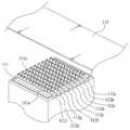
이러한 상향식 또는 하향식 전기방사장치 중 하향식 전기방사장치는 도 1에서 도시하고 있는 바와 같이, 고분자 방사용액이 충진되는 방사용액 주탱크(120)와 상기 방사용액 주탱크(120) 내에 충진된 고분자 방사용액을 정량으로 공급하기 위한 계량 펌프(미도시)와 상기 방사용액 주탱크 내의 고분자 방사용액을 토출하되, 핀 형태로 이루어지는 노즐(111a)이 다수개로 배열설치되는 노즐블록(111)과 상기 노즐(111a)에서 분사되는 고분자 방사용액을 집적하기 위하여 노즐(111a)에서 일정간격 이격격되게 설치되는 컬렉터(113) 및 상기 컬렉터(113)에 고전압을 발생시키는 전압 발생장치(114)를 포함하는 적어도 하나 이상의 유닛(110, 110')으로 구성된다.As shown in FIG. 1, the top-down electrospinning device of the bottom-up or top-down electrospinning device includes a spinning solution
이러한 전기방사장치(100)를 통한 나노 섬유필터의 제조방법은 방사용액 주탱크(120) 내에 충진되는 고분자 방사용액이 계량 펌프를 통해 높은 전압이 부여되는 노즐블록(111)으로 연속적으로 정량 공급되고, 상기 노즐블록(111)으로 공급되는 고분자 방사용액은 높은 전압이 걸려있는 컬렉터(113) 상에 노즐(111a)을 통하여 전기방사장치(100) 내에서 이송되는 기재(115) 상에 방사 및 집속되어 나노 섬유필터가 적층형성된다.In the method of manufacturing the nanofiber filter through the
이때, 상기 전기방사장치(100)는 이송롤러(116b) 사이에서 회전되는 이송벨트(116a)에 의해 기재(115)가 이송된다.At this time, in the
상술한 바와 같은 전기방사장치를 통하여 고분자 방사용액을 전기방사하여 제조된 나노 섬유필터를 산업현장에서 사용되는 필터 소재로 적용할 경우, 필터 소재로 사용되는 전체 나노 섬유필터의 평량이 일정 및 균일해야만 표준규격을 만족하여 제품의 생산 및 판매가 가능하였는데, 실제 화력발전소의 가스터빈등에 사용되는 필터의 경우, 공기가 유입되는 방향, 공기의 유입부분 위치, 공기의 배기부분 방향 및 배기부분의 위치에 따라 필터 소재를 구성하는 나노 섬유필터의 평량이 일정할 필요가 없는 경우도 있으며, 오히려 공기여과가 활발한 필터 부분은 공기여과 효율을 높이기 위해 나노 섬유필터의 평량을 작게 조절하여야 하는 반면, 공기여과가 활발하지 않은 필터 부분은 공기유량이 많지 않으므로 나노 섬유필터의 평량을 크게 조절하여 공기여과 측면보다 내구성을 높이는 설계의 요구가 필요한 실정이다.When the nanofiber filter manufactured by electrospinning a polymer spinning solution through the electrospinning device as described above is used as a filter material used in an industrial field, the basis weight of the entire nanofiber filter used as the filter material must be constant and uniform In the case of a filter used in a gas turbine of a thermal power plant, it is possible to manufacture and sell products satisfying the standard specifications. Depending on the direction of air inflow, the position of the inflow portion of the air, the direction of the air portion of the air, In some cases, the basis weight of the nanofiber filter constituting the filter material does not need to be constant. On the other hand, in the filter portion in which air filtration is active, the basis weight of the nanofiber filter should be controlled to be small in order to increase the air filtering efficiency. Since the air filter does not have a large air flow rate, the basis weight of the nanofiber filter There is a need for a design that is more durable than the air filtration side.
이렇게, 나노 섬유필터의 평량은 공기유입부와 배출구의 위치에 따라 동일 나노 섬유필터 상에서도 상이한 평량을 갖는 나노 섬유필터 소재가 요구되고 있는 실정이다.Thus, the basis weight of the nanofiber filter is required to be a nanofiber filter material having different basis weights on the same nanofiber filter depending on the positions of the air inlet and outlet.
이에 본 발명은 상기와 같은 문제를 해결하기 위해 이루어진 것으로서, 나노 섬유필터 제작 시, 내마모성과 생산성을 높이기 위해, 나노 섬유필터층의 평면방향 중 길이 방향(MD)으로 평량이 상이한 나노 섬유필터 및 이의 제조방법을 제공하는 것을 목적으로 한다.Accordingly, the present invention has been made to solve the above-mentioned problems, and it is an object of the present invention to provide a nanofiber filter having different basis weights in the longitudinal direction (MD) of the nanofiber filter layer in the planar direction of the nanofiber filter layer in manufacturing the nanofiber filter, And a method thereof.
상기한 과제를 해결하기 위하여 본 발명은In order to solve the above problems,
기재와;A substrate;
상기 기재상에 전기방사에 의하여 적층 형성되는 하나 이상의 나노섬유층과;At least one nanofiber layer laminated on the substrate by electrospinning;
상기 기재와 나노섬유층 및 나노섬유층간 사이에 형성되는 접착층으로 구성되는 나노섬유필터의 제조방법에 있어서,And a bonding layer formed between the substrate, the nanofiber layer and the nanofiber layer, the method comprising:
상기 나노섬유층은 길이 방향(MD)으로 나노섬유의 평량이 상이하고,Wherein the nanofiber layer has different basis weights of the nanofibers in the longitudinal direction (MD)
상기 접착층은 저융점 고분자 용액을 전기방사한 것을 특징으로 한 나노섬유필터의 제조방법를 과제 해결을 위한 수단으로 제공한다.Wherein the adhesive layer is formed by electrospinning a low-melting-point polymer solution, and provides a method for manufacturing a nanofiber filter.
본 발명은 길이 방향(MD)으로 평량이 상이한 나노 섬유필터를 제공함으로써, 내구성 향상 및 나노섬유 제조의 생산성을 높일 수 있다.The present invention can improve the durability and the productivity of nanofiber production by providing a nanofiber filter having different basis weights in the longitudinal direction (MD).
도 1은 나노 섬유필터 전기방사장치를 개략적으로 나타내는 측면도,
도 2는 본 발명에 의한 나노 섬유필터 전기방사장치의 노즐블록에 배열설치되는 노즐관체를 개략적으로 나타내는 평면도,
도 3은 본 발명에 의한 나노 섬유필터 전기방사장치의 노즐블록에 배열설치되는 노즐관체를 개략적으로 나타내는 사시도,
도 4는 본 발명에 의한 나노 섬유필터 전기방사장치의 노즐블록에 배열되는 노즐관체를 개략적으로 나타내는 측면도,
도 5 내지 도 6은 본 발명에 의한 나노 섬유필터 전기방사장치의 각 노즐관체의 노즐을 통하여 고분자 방사용액이 기재의 동일 평면 상에 전기방사되는 동작과정(도 5에서 파선으로 표시된 노즐이 폐쇄된 노즐을 나타내고, 도 6에서 파선으로 표시된 노즐은 기재 하부에 위치하는 것을 나타냄)을 개략적으로 나타내는 평면도,
도 7 내지 도 8은 본 발명에 의해 제조된 길이 방향(MD)으로 평량이 나노 섬유필터의 평면도.1 is a side view schematically showing a nanofiber filter electrospinning device,
2 is a plan view schematically showing a nozzle body arranged in a nozzle block of a nanofiber filter electrospinning apparatus according to the present invention,
3 is a perspective view schematically showing a nozzle body arranged in a nozzle block of a nanofiber filter electrospinning apparatus according to the present invention,
4 is a side view schematically showing a nozzle body arranged in a nozzle block of a nanofiber filter electrospinning apparatus according to the present invention,
FIGS. 5 to 6 are diagrams showing an operation process in which the polymer spinning solution is electrospun on the same plane of the substrate through the nozzles of each nozzle tube of the nanofiber filter electrospinning apparatus according to the present invention (in FIG. 5, A nozzle indicated by a broken line in Fig. 6 is located at a lower portion of the substrate); Fig.
Figures 7 to 8 are plan views of a nanofiber filter in a longitudinal direction (MD) produced by the present invention.
나노섬유를 제조 및 생산하기 위한 전기방사장치는 방사용액이 내부에 충진되는 방사용액 주탱크, 방사용액의 정량 공급을 위한 계량 펌프, 방사용액을 토출하기 위한 노즐이 다수개 배열설치되는 노즐블록, 노즐 하단에 위치하여 방사되는 섬유들을 집적하는 컬렉터 및 전압을 발생시키는 전압 발생장치를 포함하여 구성된다.An electrospinning device for manufacturing and producing nanofibers includes a spinning liquid main tank filled with spinning solution, a metering pump for supplying a fixed amount of spinning solution, a nozzle block having a plurality of nozzles for discharging spinning solution, And a voltage generating device for generating a voltage and a collector for accumulating the fibers that are positioned at the lower end of the nozzle and emit radiation.
상술한 바와 같은 구조로 이루어지는 전기방사장치는 방사용액이 충진되는 방사용액 주탱크와 상기 방사용액 주탱크 내에 충진된 고분자 방사용액의 정량 공급을 위한 계량 펌프와 상기 방사용액 주탱크 내의 고분자 방사용액을 토출하되, 핀 형태로 이루어지는 노즐이 다수개 배열설치되는 노즐 블록과 상기 노즐의 상단에 위치하여 분사되는 고분자 방사용액을 집적하기 위하여 노즐에서 일정간격 이격되는 컬렉터 및 상기 컬렉터에 고전압을 발생시키는 전압 발생장치를 포함하는 유닛으로 구성된다.The electrospinning device having the above-described structure includes a spinning liquid main tank filled with a spinning solution, a metering pump for supplying a fixed amount of the polymer spinning solution filled in the spinning solution main tank, and a polymer spinning solution in the spinning solution main tank A nozzle block having a plurality of nozzles arranged in a pin shape and arranged to discharge the polymer solution, and a collector disposed at an upper end of the nozzle and spaced apart from the nozzle by a predetermined distance in order to accumulate the polymer solution, And a unit including the apparatus.
여기서, 전기방사장치는 컬렉터 상의 위치하는 방향에 따라 상향식 전기방사장치, 하향식 전기방사장치 및 수평식 전기방사장치로 나뉜다. 즉, 전기방사장치는 컬렉터가 노즐의 상단에 위치하는 구성으로 이루어지고, 균일하고 상대적으로 가는 나노 섬유필터를 제조할 수 있는 상향식 전기방사장치, 컬렉터가 노즐의 하단에 위치하는 구성으로 이루어지고, 상대적으로 굵은 나노 섬유필터를 제조할 수 있으며, 단위시간 당 나노섬유의 생산량을 증대시킬 수 있는 하향식 전기방사장치 및 컬렉터와 노즐이 수평방향으로 배열되는 구성으로 이루어지는 수평식 전기방사장치로 나뉜다.Here, the electrospinning device is divided into a bottom-up electrospinning device, a top-down electrospinning device, and a horizontal electrospinning device depending on the direction on the collector. That is, the electrospinning device has a configuration in which the collector is located at the upper end of the nozzle, and a bottom-up electrospinning device capable of manufacturing a uniform and relatively thin nanofiber filter, a collector is disposed at the lower end of the nozzle, A top-down electrospinning device capable of producing a relatively thick nanofiber filter and capable of increasing the production amount of nanofibers per unit time, and a horizontal electrospinning device having a collector and nozzles arranged in a horizontal direction.
상향식 전기방사장치는 상향 노즐 블록의 노즐을 통하여 방사용액이 분사되고, 분사되는 방사용액이 지지체의 하부면에 적층되면서 나노 섬유필터를 형성하는 구성으로 이루어진다.The bottom-up electrospinning device has a configuration in which a spinning solution is injected through a nozzle of an upward nozzle block, and a spinning solution to be injected is deposited on a lower surface of the support to form a nanofiber filter.
상술한 바와 같은 구성에 의하여 상기 상향식 전기방사장치의 어느 한 유닛 내부에서 노즐을 통하여 방사용액을 분사하여 나노 섬유필터가 적층형성되는 장척시트는 다른 한 유닛 내부로 이송되고, 다른 한 유닛 내부로 이송되는 장척시트에 노즐을 통하여 방사용액을 분사하여 또 다시 나노섬유를 적층형성하는 등 상기한 공정을 반복적으로 수행하면서 나노 섬유필터를 제조한다.
According to the above-described configuration, the elongated sheet in which the spinning solution is injected through one of the nozzles of the bottom-up electrospinning device so as to laminate the nanofiber filters is conveyed to the inside of the other unit, A nanofiber filter is manufactured by repeatedly performing the above-described processes such as spraying a spinning solution through a nozzle onto a long sheet to form a laminate of nanofibers.
이하, 본 발명에 의한 바람직한 실시예와 첨부된 도면을 참조하면서 상세하게 설명한다. 또한, 본 실시예에서는 본 발명의 권리범위를 한정하는 것은 아니고, 단지 예시로 제시한 것이며, 그 기술적인 요지를 이탈하지 않는 범위 내에서 다양한 변경이 가능하다.
DETAILED DESCRIPTION OF THE PREFERRED EMBODIMENTS Hereinafter, preferred embodiments of the present invention will be described in detail with reference to the accompanying drawings. The present invention is not limited to the scope of the present invention, but is merely an example, and various modifications can be made without departing from the technical spirit of the present invention.
나노섬유란 일반적으로 평균직경이 50 내지 1000㎚ 이하인 섬유를 의미하며, 전기방사장치를 이용하여 제조가 가능하다.The nanofiber generally means a fiber having an average diameter of 50 to 1000 nm or less and can be manufactured using an electrospinning device.
전기방사장치는 전원공급장치, 방사노즐 및 컬렉터 등을 포함한다. 전원공급장치는 노즐과 컬렉터 사이에 고전압의 전계를 형성시킨다. 방사노즐은 방사공간 쪽으로 방사용액을 공급한다. 컬렉터는 전기방사된 나노섬유를 집속한다. 전기방사장치의 방사공간에서 형성된 필라멘트는 방사조건에 따라 다양한 평균직경을 가질 수 있으며, 50 내지 1000㎚의 평균직경을 가지는 나노섬유일 수 있다.
The electrospinning apparatus includes a power supply, a spinning nozzle, a collector, and the like. The power supply forms an electric field of high voltage between the nozzle and the collector. The spinning nozzle supplies spinning solution to the spinning space. The collector concentrates the electrospun nanofibers. The filaments formed in the spinning space of the electrospinning device may have various average diameters depending on spinning conditions, and may be nanofibers having an average diameter of 50 to 1000 nm.
도 2는 본 발명에 의한 나노 섬유필터 전기방사장치의 노즐블록에 배열설치되는 노즐관체를 개략적으로 나타내는 평면도이고, 도 3은 본 발명에 의한 나노 섬유필터 전기방사장치의 노즐블록에 배열설치되는 노즐관체를 개략적으로 나타내는 사시도이며, 도 4는 본 발명에 의한 나노 섬유필터 전기방사장치의 노즐블록에 배열되는 노즐관체를 개략적으로 나타내는 측면도이고, 도 5 내지 도 6은 본 발명에 의한 나노 섬유필터 전기방사장치의 각 노즐관체의 노즐을 통하여 고분자 방사용액이 기재의 동일 평면 상에 전기방사되는 동작과정을 개략적으로 나타내는 평면도이다.FIG. 2 is a plan view schematically showing a nozzle body arranged in a nozzle block of a nanofiber filter electrospinning apparatus according to the present invention, and FIG. 3 is a cross-sectional view of a nozzle block arranged in the nozzle block of the nanofiber filter electrospinning apparatus according to the present invention. 4 is a side view schematically showing a nozzle body arranged in a nozzle block of a nanofiber filter electrospinning apparatus according to the present invention, and FIGS. 5 to 6 show a nanofiber filter electrospinning apparatus according to the present invention, FIG. 2 is a plan view schematically showing an operation process in which a polymer spinning solution is electrospun on the same plane of a substrate through a nozzle of each nozzle tube of the spinning device. FIG.
도 1을 참조하여 설명하면, 도면에서 도시하고 있는 바와 같이, 본 발명에 의한 전기방사장치(100)는 상향식 전기방사장치로 이루어지되, 저융점 고분자 유닛(110)과 방사용액 유닛(110‘)으로 이루어진다. 본 발명의 일 실시예에서는 상기 전기방사장치(100)가 상향식 전기방사장치로 이루어져 있으나, 하향식 전기방사장치로 이루어지는 것도 가능하다.1, the
여기서, 상기 저융점 고분자 유닛(110)에는 접착층을 형성하기 위한 저융점 고분자 용액이 전기방사되며, 상기 방사용액 유닛(110‘)에는 나노섬유층을 형성하기 위한 고분자 용액이 전기방사된다.Here, a low melting point polymer solution for forming an adhesive layer is electrospinned to the low melting
상기 저융점 고분자 유닛(110) 및 방사용액 유닛(110‘)은 각각 주탱크(120)와 연결된다.The low melting
상기 방사용액 주탱크(120) 내에 충진된 방사용액을 정량으로 공급하기 위한 계량 펌프(미도시)와 상기 방사용액 주탱크(120) 내의 고분자 방사용액을 토출하되, 핀 형태로 이루어지는 노즐(111a)이 다수개로 구비되는 노즐관체(112)가 기재(115)의 폭방향으로 다수개 배열설치되는 노즐블록(111)과 상기 노즐(111a)에서 분사되는 고분자 방사용액을 집적하기 위하여 노즐(111a)에서 일정간격 이격격되게 설치되는 컬렉터(113) 및 상기 컬렉터(113)에 고전압을 발생시키는 전압 발생장치(114)를 포함하여 구성된다.(Not shown) for supplying the spinning liquid filled in the spinning liquid
상기 저융점 고분자 용액은 상기 저융점 폴리우레탄은 연화온도가 80-100℃인 저중합도 폴리우레탄을 사용한다.In the low melting point polymer solution, the low melting point polyurethane is a low degree of polymerization polyurethane having a softening temperature of 80-100 ° C.
상기 저융점 폴리에스테르는 테레프탈산, 이소프탈산 및 이들의 혼합물을 사용하는 것이 좋다. 여기에 융점을 더욱 강하시키기 위하여 디올성분으로 에틸렌글리콜(ethylene glycol)을 첨가하는 것도 무방하다.The low melting point polyester is preferably terephthalic acid, isophthalic acid or a mixture thereof. It is also possible to add ethylene glycol as a diol component to further lower the melting point.
상기 저융점 폴리비닐리덴 플루오라이드는 중량 평균 분자량 5,000이고 융점 80~160℃인 저융점 폴리비닐리덴 플루오라이드를 사용한다.The low melting point polyvinylidene fluoride is a low melting point polyvinylidene fluoride having a weight average molecular weight of 5,000 and a melting point of 80 to 160 ° C.
상기한 저융점 폴리우레탄, 저융점 폴리에스테르, 저융점 폴리비닐리덴 플루오라이드는 단독 또는 2종 이상을 혼합하여 사용할 수 있음은 물론이다.It is needless to say that the low melting point polyurethane, the low melting point polyester and the low melting point polyvinylidene fluoride may be used singly or in combination of two or more.
상기한 바와 같은, 나노 섬유필터 전기방사장치(1)는 방사용액 주탱크(120) 내에 충진되는 고분자 방사용액이 계량 펌프를 통해 높은 전압이 부여되는 노즐블록(111)으로 연속적으로 정량 공급되고, 노즐블록(111)으로 공급되는 고분자 방사용액은 높은 전압이 걸려있는 컬렉터(113) 상에 노즐(111a)을 통하여 전기방사장치 내에서 이송되는 기재(115) 상에 방사 및 집속되어 나노 섬유필터가 적층형성된다.In the nanofiber filter electrospinning device 1 as described above, the polymer spinning solution filled in the spinning liquid
이때, 상기 나노 섬유필터 전기방사장치(1)에 구비되는 적어도 하나 이상의 유닛(110, 110')은 일정간격 이격되어 순차적으로 구비되되, 각 유닛(110, 110')을 통하여 고분자 방사용액이 전기방사되어 나노 섬유필터를 제조한다.At least one or
한편, 상기 전기방사장치(100)의 노즐블록(111)은 그 폭방향으로 다수개의 노즐관체(112)가 배열설치되고, 상기 노즐관체(112)에 고분자 방사용액을 공급하는 방사용액 주탱크(120)가 적어도 하나 이상 연결구비된다.The
즉, 직육면체형상으로 형성되되, 그 상부면에 다수개의 노즐(111a)이 선형으로 구비되는 노즐관체(112a, 112b, 112c, 112d, 112e, 112f, 112g, 112h, 112i)가 노즐블록(111)에 기재(115)의 폭방향으로 다수개 배열설치되고, 상기 각 노즐관체(112a, 112b, 112c, 112d, 112e, 112f, 112g, 112h, 112i)는 방사용액 주탱크(120)에 연결되어 상기 방사용액 주탱크(120) 내에 충진된 고분자 방사용액이 공급된다.The
여기서, 상기 각 노즐관체(112a, 112b, 112c, 112d, 112e, 112f, 112g, 112h, 112i)는 방사용액 주탱크(120)에 용액공급관(121)으로 연결되되, 상기 용액공급관(121)은 다수개의 노즐관체(112a, 112b, 112c, 112d, 112e, 112f, 112g, 112h, 112i)와 방사용액 주탱크(120)를 연결하기 위하여 다수개로 분기형성된다.Here, the
이때, 상기 방사용액 주탱크(120)에서 각 노즐관체(112a, 112b, 112c, 112d, 112e, 112f, 112g, 112h, 112i)로 연설되는 용액공급관(121)에는 공급량 조절수단(도번 미도시)이 구비되되, 상기 공급량 조절수단은 공급밸브(122)로 이루어진다.At this time, a supply amount adjusting means (not shown) is connected to the solution supply pipe 121, which is communicated to the
이렇게 상기 방사용액 주탱크(120)에서 각 노즐관체(112a, 112b, 112c, 112d, 112e, 112f, 112g, 112h, 112i)로 연설되는 용액공급관(121)에 공급밸브(122)가 각각 구비되고, 상기 각 공급밸브(122)에 의하여 방사용액 주탱크(120)에서 각 노즐관체(112a, 112b, 112c, 112d, 112e, 112f, 112g, 112h, 112i)로 공급되는 고분자 방사용액의 공급이 조절 및 제어되는 on-off 시스템에 의해 제어된다.A
즉, 상기 용액공급관(121)을 통하여 방사용액 주탱크(120)에서 각 노즐관체(112a, 112b, 112c, 112d, 112e, 112f, 112g, 112h, 112i)로 고분자 방사용액의 공급 시 상기 방사용액 주탱크(120)와 각 노즐관체(112a, 112b, 112c, 112d, 112e, 112f, 112g, 112h, 112i)를 연설하는 용액공급관(121)에 구비되는 공급밸브(122)의 개, 폐에 의해 노즐블록(111)에 배열설치되는 노즐관체(112a, 112b, 112c, 112d, 112e, 112f, 112g, 112h, 112i) 중 특정위치의 노즐관체(112b, 112d, 112f, 112g, 112h, 112i)에만 선택적으로 고분자 방사용액을 공급하는 등 상기 공급밸브(122)의 개, 폐에 의해 방사용액 주탱크(120)에서 각 노즐관체(112a, 112b, 112c, 112d, 112e, 112f, 112g, 112h, 112i)로 공급되는 고분자 방사용액의 공급이 조절 및 제어된다.That is, when the polymer spinning solution is supplied to the
이를 위하여 상기 공급밸브(122)는 제어부(미도시)에 제어가능하게 연결되되, 상기 공급밸브(122)의 개, 폐가 제어부에 의해 자동으로 제어되는 것이 바람직하나, 현장상황 및 작업자의 요구에 따라 상기 공급밸브(122)의 개, 폐가 수동으로 제어되도록 이루어지는 것도 가능하다.For this purpose, the
본 발명의 일 실시예에서는 상기 공급량 조절수단이 공급밸브(122)로 이루어져 있으나, 방사용액 주탱크(120)에서 각 노즐관체(112a, 112b, 112c, 112d, 112e, 112f, 112g, 112h, 112i)로 공급되는 고분자 방사용액의 공급량의 조절 및 제어가 용이하다면 상기 공급량 조절수단은 기타 다양한 구조 및 수단으로 이루어지는 것도 가능하며, 이에 한정하지 아니한다.112b, 112c, 112d, 112e, 112f, 112g, 112h, 112i in the spinning liquid
상기한 바와 같은 구조에 의하여, 상기 방사용액 주탱크(120)와 각 노즐관체(112a, 112b, 112c, 112d, 112e, 112f, 112g, 112h, 112i)를 연설하되, 분기형성되는 용액공급관(121)에 공급밸브(122)가 각각 구비되어 방사용액 주탱크(120)에서 각 노즐관체(112a, 112b, 112c, 112d, 112e, 112f, 112g, 112h, 112i)로 고분자 방사용액의 공급 시 다수개의 공급밸브(122) 중 특정 공급밸브(122)를 개방하여 노즐블록(111)에 배열설치되는 노즐관체(112a, 112b, 112c, 112d, 112e, 112f, 112g, 112h, 112i) 중 특정위치의 노즐관체(112b, 112d, 112f, 112g, 112h, 112i)에만 고분자 방사용액을 공급하거나, 특정 공급밸브(122)를 폐쇄하여 노즐블록(111)에 배열설치되는 노즐관체 중 특정위치의 노즐관체(112a, 112c, 112e)에만 고분자 방사용액의 공급을 차단하는 등 상기 공급밸브(122)의 개, 폐에 의해 방사용액 주탱크(120)에서 각 노즐관체(112a, 112b, 112c, 112d, 112e, 112f, 112g, 112h, 112i)로 공급되는 고분자 방사용액의 공급이 조절 및 제어된다.The solution supply pipe 121 is connected to the spinning solution
한편, 상기 방사용액 주탱크(120)에서 용액공급관(121)을 통하여 각 노즐관체(112a, 112b, 112c, 112d, 112e, 112f, 112g, 112h, 112i)로 공급되는 고분자 방사용액은 상기 용액공급관(121)에 연설되는 노즐공급관(125)을 통하여 노즐관체(112a, 112b, 112c, 112d, 112e, 112f, 112g, 112h, 112i)에 구비되는 각 노즐(111a)로 공급된다.The polymer spinning solution supplied to the
즉, 상기 용액공급관(121)과 노즐관체(112a, 112b, 112c, 112d, 112e, 112f, 112g, 112h, 112i)에 구비되는 각 노즐(111a)은 노즐공급관(125)으로 연설되되, 상기 노즐공급관(125)은 노즐(111a)의 갯수와 대응되게 분기형성된다.That is, the
여기서도, 상기 노즐공급관(125)에는 방사량 조절수단(도번 미도시)이 구비되되, 상기 방사량 조절수단은 노즐밸브(126)로 이루어진다.Here, the
이렇게, 상기 방사량 조절수단으로 노즐밸브(126)가 구비됨으로써 상기 노즐밸브(126)의 개, 폐에 의하여 노즐공급관(125)에서 각 노즐(111a)로 공급되는 고분자 방사용액의 공급이 개별적으로 제어되고, 상기 노즐밸브(126)는 제어부(미도시)에 제어가능하게 연결되되, 상기 노즐밸브(126)의 개, 폐가 제어부에 의해 자동으로 제어되는 것이 바람직하나, 현장상황 및 작업자의 요구에 따라 상기 노즐밸브(126)의 개, 폐가 수동으로 제어되도록 이루어지는 것도 가능하다.The supply of the polymer solution to be supplied to each
본 발명의 일 실시예에서는 상기 방사량 조절수단이 노즐밸브(126)로 이루어져 있으나, 노즐관체에서 노즐(111a)로 공급된 후 방사되는 고분자 방사용액의 방사량의 조절 및 제어가 용이하다면 상기 방사량 조절수단은 기타 다양한 구조 및 수단으로 이루어지는 것도 가능하며, 이에 한정하지 아니한다.In an embodiment of the present invention, if the amount of the spinning solution of the polymer spinning solution is easily controlled and controlled after being supplied to the
상기한 바와 같은 구조에 의하여, 상기 용액공급관(121)과 각 노즐(111a)이 연결설치되되, 분기형성되는 노즐공급관(125)에 노즐밸브(126)가 각각 구비되어 방사용액 주탱크(120)에서 각 노즐관체(112a, 112b, 112c, 112d, 112e, 112f, 112g, 112h, 112i)를 통하여 각 노즐(111a)로 고분자 방사용액의 공급 시 다수개의 노즐밸브(126) 중 특정 노즐밸브(126)를 개방하여 노즐관체(112a, 112b, 112c, 112d, 112e, 112f, 112g, 112h, 112i)에 구비되는 각 노즐(111a) 중 특정위치의 노즐(111a)에서만 선택적으로 고분자 방사용액이 전기방사되거나, 특정 노즐밸브(126)를 폐쇄하여 노즐관체(112a, 112b, 112c, 112d, 112e, 112f, 112g, 112h, 112i)에 구비되는 각 노즐(111a) 중 특정위치의 노즐(111a)에서 고분자 방사용액의 전기방사를 선택적으로 차단하는 등 상기 노즐밸브(126)에 의해 방사용액 주탱크(120)에서 노즐관체(112a, 112b, 112c, 112d, 112e, 112f, 112g, 112h, 112i)를 통하여 각 노즐(111a)로 공급되는 고분자 방사용액의 공급이 개별적으로 조절 및 제어된다.According to the structure described above, the solution supply pipe 121 and the
본 발명의 일 실시예에서는 상기 용액공급관(121)에 공급밸브(122)가 구비되어 상기 방사용액 주탱크(120)에서 노즐블록(111)의 각 노즐관체(112a, 112b, 112c, 112d, 112e, 112f, 112g, 112h, 112i)로 공급되는 고분자 방사용액의 공급량을 조절 및 제어함과 동시에 상기 노즐공급관(125)에 노즐밸브(126)가 구비되어 상기 노즐관체(112a, 112b, 112c, 112d, 112e, 112f, 112g, 112h, 112i)에서 공급되어 각 노즐(111a)을 통하여 전기방사되는 고분자 방사용액의 방사량을 조절 및 제어함으로써 상기 노즐관체(112a, 112b, 112c, 112d, 112e, 112f, 112g, 112h, 112i)의 각 노즐(111a)에서 전기방사되는 고분자 방사용액에 의해 기재(115)의 폭 방향에 평량이 상이한 나노 섬유필터를 적층형성하도록 이루어져 있으나, 상기 노즐블록(111)에 노즐(111a)을 배열설치한 후 각 노즐(111a)이 개별적으로 직접 조절 및 제어되어 상기 각 노즐(111a)을 통하여 전기방사되는 고분자 방사용액의 방사량을 조절 및 제어함으로써 기재(115)의 폭 방향에 평량이 상이한 나노 섬유필터를 적층형성하도록 이루어지는 것도 가능하며, 이에 한정하지 아니한다.
In an embodiment of the present invention, the solution supply pipe 121 is provided with a
본 발명에 사용되는 MD방향이란 Machine Direction을 의미하며, 필름이나 부직포 등의 섬유를 연속제조하는 경우에 진행방향에 해당하는 길이 방향을 의미한다.The MD direction used in the present invention means a machine direction, and means a length direction corresponding to a traveling direction when a fiber such as a film or a nonwoven fabric is continuously produced.
평량(Basis Weight or Grammage)은 단위 면적당 질량, 즉 바람직한 단위로서 제곱미터당 그램(g/㎡)으로 정의된다.Basis Weight or Grammage is defined as the mass per unit area, that is, the preferred unit, grams per square meter (g / m 2).
독립된 노즐블럭을 기반으로 on-off 시스템으로 기재상에 적층되는 고분자 용액의 평량을 상이하게 조절할 수 있다. 통상적으로 나노 섬유필터층의 평량은 용도에 따라 적절히 선택할 수 있지만, 평량이 0.1 내지 0.5g/㎡의 범위에 있다.
An on-off system based on an independent nozzle block can control the basis weight of the polymer solution stacked on the substrate differently. Typically, the basis weight of the nanofiber filter layer can be appropriately selected depending on the application, but the basis weight is in the range of 0.1 to 0.5 g / m 2.
이하, 본 발명에서 사용되는 고분자에 대하여 설명한다. 본 발명의 고분자 및 그에 바람직한 것으로 폴리비닐리덴플루오라이드, 폴리우레탄 및 나일론이 있다.Hereinafter, the polymer used in the present invention will be described. Polymers of the present invention and polyvinylidene fluoride, polyurethane and nylon are preferable for the polymer.
먼저, 상기 고분자는 폴리비닐리덴플루오라이드, 폴리비닐리덴 플루오라이드-헥사플루오르 프로필렌 공중합체, 혹은 이들의 복합 조성물, 폴리우레탄, 폴리아마이드, 폴리이미드, 폴리아미드이미드, 폴리(메타-페닐렌 이소프탈아미이드), 메타아라미드, 폴리에틸렌클로로트리플루오로에틸렌, 폴리클로로트리플루오로에틸렌, 폴리메틸메타크릴레이트, 폴리아크릴로니트릴, 폴리비닐리덴클로라이드, 폴리비닐리덴클로라이드-아크릴로니트릴 공중합체, 폴리아크릴아미드 등으로 구성되는 군에서 선택된 어느 하나 이상의 물질이다.
The polymer may be at least one selected from the group consisting of polyvinylidene fluoride, polyvinylidene fluoride-hexafluoropropylene copolymer, or a composite composition thereof, a polyurethane, a polyamide, a polyimide, a polyamideimide, a poly (meta-phenylene isophthalate Amide), meta-aramid, polyethylene chlorotrifluoroethylene, polychlorotrifluoroethylene, polymethylmethacrylate, polyacrylonitrile, polyvinylidene chloride, polyvinylidene chloride-acrylonitrile copolymer, polyacrylic Amide, and the like.
이하, 본 발명을 구체적으로 설명하기 위해 실시예를 들어 상세하게 설명하기로 한다. 그러나 본 발명에 따른 실시예들은 여러가지 다른 형태로 변형될 수 있으며, 본 발명의 범위가 아래에서 상술하는 실시예들에 한정되는 것으로 해석되어져서는 안된다. 본 발명의 실시예들은 당업계에서 평균적인 지식을 가진 자에게 본 발명을 보다 완전하게 설명하기 위해서 제공되는 것이다.
BEST MODE FOR CARRYING OUT THE INVENTION Hereinafter, the present invention will be described in detail with reference to examples. However, the embodiments according to the present invention can be modified into various other forms, and the scope of the present invention should not be construed as being limited to the embodiments described below. Embodiments of the invention are provided to more fully describe the present invention to those skilled in the art.
실시예에서의 물성 값은 이하의 방법에 의해 측정했다.
The physical property values in the examples were measured by the following methods.
실시예1Example 1
연화온도가 80-100℃인 저중합도 폴리우레탄을 DMAc(N,N-dimethylaceticamide) 용매에 15중량%가 되도록 용해하여 저융점 고분자 용액을 제조하고 전기방사장치의 저융점 고분자 유닛(110)의 주탱크에 투입하였다. 또한 중량평균분자량이 50,000인 폴리비닐리덴 플루오라이드를 디메틸아세트아미드(N,N-Dimethylacetamide, DMAc)에 용해시켜 각각의 방사용액을 제조하고, 이를 방사용액 유닛(110‘)와 연결된 주탱크에 투입하였다.Melting
저융점 고분자 유닛(110)에서 전극과 컬렉터 간의 거리를 40cm, 인가전압 25kV, 70℃에서 전기방사하여 평량 0.1g/m2인 접착층을 셀룰로오스 기재위에 형성하였고, 이어서 방사용액 유닛(110‘)에서 전극과 컬렉터 간의 거리를 40cm, 인가전압 20kV, 70℃에서 길이 방향(MD) 중 일방향으로 1m는 폴리비닐리덴 플루오라이드 나노섬유의 평량이 0.2g/m2이고 나머지 일방향으로 1m는 나노섬유의 평량이 0.5g/m2인 MD 폭이 2m인 나노섬유필터를 제조하였다.The adhesive layer having a basis weight of 0.1 g / m <2 > was formed on the cellulose substrate by the electrospinning of the distance between the electrodes and the collector at 40 cm, the application voltage 25 kV, and 70 DEG C in the low melting
실시예2Example 2
중량평균 분자량이 157,000인 폴리우레탄을 디메틸포름아마이드(DMF)에 용해시켜 폴리우레탄 용액을 제조한다. 상기 폴리우레탄 용액을 방사용액 주탱크 각각에 투입하고 길이 방향(MD) 중 한 방향으로 노즐블럭이 3부분으로 분리되어 있게 설계된 on-off시스템을 포함한 노즐블록에 인가전압을 20kV로 부여하고, 평량 3g/m2인 기재 상에 전기방사하였다. 전기방사된 컬렉터 상에 길이 방향(MD) 중 중간부분 1m는 평량이 0.5/m2의 폴리우레탄 나노섬유가, 나머지 가장자리 50cm은 평량이 0.2g/m2으로 MD 폭이 2m인 폴리우레탄 나노섬유가 형성되어 폴리우레탄 나노 섬유필터를 제조하였다. 이 때 전극과 컬렉터 간의 거리를 40cm, 온도 22℃의 조건으로 상향식 전기방사를 실시하였다.
A polyurethane solution having a weight average molecular weight of 157,000 is dissolved in dimethylformamide (DMF) to prepare a polyurethane solution. The polyurethane solution was put into each of the spinning liquid main tanks and the applied voltage was applied at 20 kV to the nozzle block including the on-off system designed so that the nozzle block was separated into three parts in one direction in the longitudinal direction (MD) 3 g / m <2 & gt ;. Electrical intermediate portion 1m of the radiation on the collector longitudinal direction (MD) is a polyester having a weight of 0.5 / m2 polyurethane nanofibers, and the other edge is 50cm with a basis weight of 0.2g / m2 in the MD width 2m polyurethane nanofiber To form a polyurethane nanofiber filter. At this time, bottom-up electrospinning was performed under the condition that the distance between the electrode and the collector was 40 cm and the temperature was 22 ° C.
실시예3Example 3
중량평균 분자량이 157,000인 폴리우레탄을 디메틸포름아마이드(DMF)에 용해시켜 폴리우레탄 용액을 제조한다. 상기 폴리우레탄 용액을 방사용액 주탱크에 투입하고 길이 방향(MD) 중 한 방향으로 노즐블럭이 9부분으로 분리되어 있게 설계된 on-off시스템을 포함한 노즐블록에 인가전압을 20kV로 부여하고, 평량 0.3g/m2인 기재 상에 전기방사하였다. 전기방사된 셀룰로오스 기재 상에 길이 방향(MD)으로 교호적으로 폴리우레탄 나노섬유의 평량이 0.2g/m2이고 나머지 부분의 평량이 0.5g/m2인 MD 폭이 2m인 폴리우레탄 나노섬유가 형성되어 폴리우레탄 나노 섬유필터를 제조하였다. 이 때 전극과 컬렉터 간의 거리를 40cm, 온도 22℃의 조건으로 상향식 전기방사를 실시하였다.A polyurethane solution having a weight average molecular weight of 157,000 is dissolved in dimethylformamide (DMF) to prepare a polyurethane solution. The polyurethane solution was injected into the spinning liquid main tank and applied voltage of 20 kV to the nozzle block including the on-off system designed to divide the nozzle block into 9 parts in one direction in the longitudinal direction (MD) g / m <2 & gt ;. Polyurethane nanofibers having a basis weight of polyurethane nanofiber of 0.2 g / m2 alternately in the longitudinal direction (MD) on the electrospun cellulose substrate and having a MD width of 2 m, the basis weight of which is 0.5 g / m2 , To prepare a polyurethane nanofiber filter. At this time, bottom-up electrospinning was performed under the condition that the distance between the electrode and the collector was 40 cm and the temperature was 22 ° C.
100 : 전기방사장치,110, 110' : 유닛,
111 : 노즐블록,111a : 노즐,
112 : 노즐관체,
112a, 112b, 112c, 112d, 112e, 112f, 112g, 112h, 112i : 노즐관체
113 : 컬렉터,114 : 전압발생장치,
115 : 기재,
115a, 115b, 115c : 나노 섬유필터,
116a : 이송벨트, 116b : 이송롤러,
120 : 방사용액 주탱크, 121 : 용액공급관,
122 : 공급밸브, 125 : 노즐공급관,
126 : 노즐밸브.
a, b, c, d, e, f : 상이한 평량의 나노섬유100: electrospinning device, 110, 110 ': unit,
111: nozzle block, 111a: nozzle,
112: nozzle body,
112a, 112b, 112c, 112d, 112e, 112f, 112g, 112h, 112i:
113: collector, 114: voltage generator,
115: substrate,
115a, 115b and 115c: nanofiber filters,
116a: conveying belt, 116b: conveying roller,
120: spinning liquid main tank, 121: solution supply pipe,
122: supply valve, 125: nozzle supply pipe,
126: Nozzle valve.
a, b, c, d, e, f: different basis weights of nanofibers
Claims (7)
Translated fromKorean상기 기재상에 전기방사에 의하여 적층 형성되는 하나 이상의 나노섬유층과;
상기 기재와 나노섬유층 및 나노섬유층간 사이에 형성되는 접착층으로 구성되는 나노섬유필터의 제조방법에 있어서,
상기 나노섬유층은 길이 방향(MD)으로 나노섬유의 평량이 상이하고,
상기 접착층은 저융점 고분자 용액을 전기방사하고,
상기 나노섬유의 평량은 복수의 노즐관체를 on-off 시스템으로 조작하는 것을 특징으로 하는 길이 방향(MD)으로 나노섬유의 평량이 상이한 나노 섬유필터의 제조방법.A substrate;
At least one nanofiber layer laminated on the substrate by electrospinning;
And a bonding layer formed between the substrate, the nanofiber layer and the nanofiber layer, the method comprising:
Wherein the nanofiber layer has different basis weights of the nanofibers in the longitudinal direction (MD)
The adhesive layer is formed by electrospinning a low melting point polymer solution,
Wherein the basis weight of the nanofibers is such that a plurality of nozzle tubes are operated by an on-off system, and the basis weight of the nanofibers is different in the longitudinal direction (MD).
상기 on-off 시스템은 나노섬유가 집적되는 길이 방향(MD) 중 일방향으로 평량의 구배가 증가하게 설계된 것을 특징으로 하는 길이 방향(MD)으로 나노섬유의 평량이 상이한 나노 섬유필터의 제조방법.The method according to claim 1,
Wherein the on-off system is designed to increase the slope of the basis weight in one direction in the longitudinal direction (MD) in which the nanofibers are integrated, wherein the basis weight of the nanofibers is different in the longitudinal direction (MD).
상기 on-off 시스템은 나노섬유가 집적되는 길이 방향(MD) 중 양방향으로 평량의 구배가 증가 또는 감소하게 설계된 것을 특징으로 하는 길이 방향(MD)으로 나노섬유의 평량이 상이한 나노 섬유필터의 제조방법.The method according to claim 1,
Wherein the on-off system is designed to increase or decrease the slope of the basis weight in both directions in the longitudinal direction (MD) in which the nanofibers are integrated. The method of manufacturing the nanofiber filter according to claim 1, .
상기 on-off 시스템은 나노섬유가 집적되는 길이 방향(MD)으로 교호적으로 평량이 상이하게 설계된 것을 특징으로 하는 길이 방향(MD)으로 나노섬유의 평량이 상이한 나노 섬유필터의 제조방법.The method according to claim 1,
Wherein the on-off system is designed such that the basis weight is alternately different in the longitudinal direction (MD) in which the nanofibers are integrated, wherein the basis weight of the nanofibers is different in the longitudinal direction (MD).
상기 평량은 0.1 내지 0.5g/m2의 범위에서 길이 방향(MD)으로 상이한 것을 특징으로 하는 길이 방향(MD)으로 나노섬유의 평량이 상이한 나노 섬유필터의 제조방법.The method according to claim 1,
Wherein the basis weight is different in the longitudinal direction (MD) in the range of 0.1 to 0.5 g / m2 , and the basis weight of the nanofibers is different in the longitudinal direction (MD).
Priority Applications (2)
| Application Number | Priority Date | Filing Date | Title |
|---|---|---|---|
| KR1020150057481AKR101778255B1 (en) | 2015-04-23 | 2015-04-23 | Nano fiber filter and method of manufacturing the same |
| PCT/KR2015/007143WO2016171329A1 (en) | 2015-04-23 | 2015-07-09 | Electrospinning device comprising temperature adjustment device, method for manufacturing nanofiber filter using same, and nanofiber filter manufactured thereby |
Applications Claiming Priority (1)
| Application Number | Priority Date | Filing Date | Title |
|---|---|---|---|
| KR1020150057481AKR101778255B1 (en) | 2015-04-23 | 2015-04-23 | Nano fiber filter and method of manufacturing the same |
Publications (2)
| Publication Number | Publication Date |
|---|---|
| KR20160126469A KR20160126469A (en) | 2016-11-02 |
| KR101778255B1true KR101778255B1 (en) | 2017-09-13 |
Family
ID=57518748
Family Applications (1)
| Application Number | Title | Priority Date | Filing Date |
|---|---|---|---|
| KR1020150057481AActiveKR101778255B1 (en) | 2015-04-23 | 2015-04-23 | Nano fiber filter and method of manufacturing the same |
Country Status (1)
| Country | Link |
|---|---|
| KR (1) | KR101778255B1 (en) |
Families Citing this family (1)
| Publication number | Priority date | Publication date | Assignee | Title |
|---|---|---|---|---|
| KR101994776B1 (en)* | 2017-08-22 | 2019-09-30 | 주식회사 대창 | Fillter including nanofiber, appartus and method manufacturing the same |
Citations (3)
| Publication number | Priority date | Publication date | Assignee | Title |
|---|---|---|---|---|
| KR101154211B1 (en)* | 2011-02-15 | 2012-07-03 | 신슈 다이가쿠 | An electrospinning apparatus and an apparatus for manufacturing nano-fiber |
| JP2012516399A (en)* | 2009-01-28 | 2012-07-19 | ドナルドソン カンパニー,インコーポレイティド | Fiber medium and method and apparatus for forming the same |
| KR101292657B1 (en)* | 2013-02-06 | 2013-08-23 | 톱텍에이치앤에스 주식회사 | A hybrid non-woven separator having the inverted structure |
- 2015
- 2015-04-23KRKR1020150057481Apatent/KR101778255B1/enactiveActive
Patent Citations (3)
| Publication number | Priority date | Publication date | Assignee | Title |
|---|---|---|---|---|
| JP2012516399A (en)* | 2009-01-28 | 2012-07-19 | ドナルドソン カンパニー,インコーポレイティド | Fiber medium and method and apparatus for forming the same |
| KR101154211B1 (en)* | 2011-02-15 | 2012-07-03 | 신슈 다이가쿠 | An electrospinning apparatus and an apparatus for manufacturing nano-fiber |
| KR101292657B1 (en)* | 2013-02-06 | 2013-08-23 | 톱텍에이치앤에스 주식회사 | A hybrid non-woven separator having the inverted structure |
Also Published As
| Publication number | Publication date |
|---|---|
| KR20160126469A (en) | 2016-11-02 |
Similar Documents
| Publication | Publication Date | Title |
|---|---|---|
| JP5150137B2 (en) | Method for producing ultrafine fiber nonwoven fabric | |
| KR101866344B1 (en) | Nano fiber filter and method of manufacturing the same | |
| KR101834404B1 (en) | Both sides substrate nanofiber web for excellent adhesion property, a separator using it and its manufacturing method | |
| KR101635037B1 (en) | Nano fiber filter and method of manufacturing the same | |
| KR101721987B1 (en) | Electrospinning devices for nano membrane | |
| KR101778255B1 (en) | Nano fiber filter and method of manufacturing the same | |
| KR101721985B1 (en) | Electrospinning devices for nano membrane | |
| KR20160126468A (en) | Nano fiber filter and method of manufacturing the same | |
| KR101527499B1 (en) | Filter comprising polyvinylidene fluoride nanofiber and bicomponent substrate and its manufacturing method | |
| KR101479757B1 (en) | Polyethersulfone nanofiber filter with excellent heat-resisting property and its method | |
| KR100658499B1 (en) | Method for manufacturing a mat coated with nanofibers and a mat made therefrom | |
| KR101721992B1 (en) | The method of making nanofiber-maskpack with MD-direction different basis weights | |
| KR101635047B1 (en) | Electrospinning devices of manufacture for nano fiber web | |
| KR101635056B1 (en) | Electrospinning devices of manufacture for nano fiber web | |
| KR20170120804A (en) | Nanofiber web with excellent adhesion, a separator using it and its method | |
| KR101778250B1 (en) | Filter including polyvinylidene fluoride nanofiber having multiple fiber-diameter group with low melting point polymer adhension layer and its manufacturing method | |
| KR101635055B1 (en) | Electrospinning devices of manufacture for nano fiber web | |
| KR101635058B1 (en) | Electrospinning devices of manufacture for nano fiber web | |
| KR101635053B1 (en) | Electrospinning devices of manufacture for nano fiber filter | |
| KR101721988B1 (en) | Nano membrane and method of manufacturing the same | |
| KR101635059B1 (en) | Electrospinning devices of manufacture for nano fiber web | |
| KR101721986B1 (en) | Nano membrane and method of manufacturing the same | |
| KR101721991B1 (en) | The method of making nanofiber-maskpack with CD-direction different basis weights | |
| KR101778265B1 (en) | Filter including polyvinyl alcohol nanofiber and hydrophobic polymer nanofiber with low melting polymer adhension layer and its manufacturing method | |
| KR101778246B1 (en) | Filter including triple nanofiber layer and with low melting polymer adhension layer and its manufacturing method |
Legal Events
| Date | Code | Title | Description |
|---|---|---|---|
| A201 | Request for examination | ||
| PA0109 | Patent application | Patent event code:PA01091R01D Comment text:Patent Application Patent event date:20150423 | |
| PA0201 | Request for examination | ||
| PG1501 | Laying open of application | ||
| E902 | Notification of reason for refusal | ||
| PE0902 | Notice of grounds for rejection | Comment text:Notification of reason for refusal Patent event date:20161205 Patent event code:PE09021S01D | |
| N231 | Notification of change of applicant | ||
| PN2301 | Change of applicant | Patent event date:20170117 Comment text:Notification of Change of Applicant Patent event code:PN23011R01D | |
| AMND | Amendment | ||
| E601 | Decision to refuse application | ||
| PE0601 | Decision on rejection of patent | Patent event date:20170417 Comment text:Decision to Refuse Application Patent event code:PE06012S01D Patent event date:20161205 Comment text:Notification of reason for refusal Patent event code:PE06011S01I | |
| AMND | Amendment | ||
| PX0901 | Re-examination | Patent event code:PX09011S01I Patent event date:20170417 Comment text:Decision to Refuse Application Patent event code:PX09012R01I Patent event date:20170203 Comment text:Amendment to Specification, etc. | |
| PX0701 | Decision of registration after re-examination | Patent event date:20170613 Comment text:Decision to Grant Registration Patent event code:PX07013S01D Patent event date:20170518 Comment text:Amendment to Specification, etc. Patent event code:PX07012R01I Patent event date:20170417 Comment text:Decision to Refuse Application Patent event code:PX07011S01I Patent event date:20170203 Comment text:Amendment to Specification, etc. Patent event code:PX07012R01I | |
| X701 | Decision to grant (after re-examination) | ||
| GRNT | Written decision to grant | ||
| PR0701 | Registration of establishment | Comment text:Registration of Establishment Patent event date:20170907 Patent event code:PR07011E01D | |
| PR1002 | Payment of registration fee | Payment date:20170908 End annual number:3 Start annual number:1 | |
| PG1601 | Publication of registration | ||
| PR1001 | Payment of annual fee | Payment date:20200727 Start annual number:4 End annual number:4 | |
| PR1001 | Payment of annual fee | Payment date:20210701 Start annual number:5 End annual number:5 | |
| PR1001 | Payment of annual fee | Payment date:20230619 Start annual number:7 End annual number:7 | |
| PR1001 | Payment of annual fee | Payment date:20240618 Start annual number:8 End annual number:8 | |
| PR1001 | Payment of annual fee | Payment date:20250618 Start annual number:9 End annual number:9 |