KR101777424B1 - Method and apparatus for receiving signal in multi-node system - Google Patents
Method and apparatus for receiving signal in multi-node systemDownload PDFInfo
- Publication number
- KR101777424B1 KR101777424B1KR1020110056675AKR20110056675AKR101777424B1KR 101777424 B1KR101777424 B1KR 101777424B1KR 1020110056675 AKR1020110056675 AKR 1020110056675AKR 20110056675 AKR20110056675 AKR 20110056675AKR 101777424 B1KR101777424 B1KR 101777424B1
- Authority
- KR
- South Korea
- Prior art keywords
- csi
- cell
- node
- virtual cell
- virtual
- Prior art date
- Legal status (The legal status is an assumption and is not a legal conclusion. Google has not performed a legal analysis and makes no representation as to the accuracy of the status listed.)
- Expired - Fee Related
Links
Images


Classifications
- H—ELECTRICITY
- H04—ELECTRIC COMMUNICATION TECHNIQUE
- H04B—TRANSMISSION
- H04B7/00—Radio transmission systems, i.e. using radiation field
- H04B7/02—Diversity systems; Multi-antenna system, i.e. transmission or reception using multiple antennas
- H04B7/022—Site diversity; Macro-diversity
- H04B7/024—Co-operative use of antennas of several sites, e.g. in co-ordinated multipoint or co-operative multiple-input multiple-output [MIMO] systems
- H—ELECTRICITY
- H04—ELECTRIC COMMUNICATION TECHNIQUE
- H04B—TRANSMISSION
- H04B7/00—Radio transmission systems, i.e. using radiation field
- H04B7/02—Diversity systems; Multi-antenna system, i.e. transmission or reception using multiple antennas
- H04B7/04—Diversity systems; Multi-antenna system, i.e. transmission or reception using multiple antennas using two or more spaced independent antennas
- H04B7/06—Diversity systems; Multi-antenna system, i.e. transmission or reception using multiple antennas using two or more spaced independent antennas at the transmitting station
- H04B7/0613—Diversity systems; Multi-antenna system, i.e. transmission or reception using multiple antennas using two or more spaced independent antennas at the transmitting station using simultaneous transmission
- H04B7/0615—Diversity systems; Multi-antenna system, i.e. transmission or reception using multiple antennas using two or more spaced independent antennas at the transmitting station using simultaneous transmission of weighted versions of same signal
- H04B7/0619—Diversity systems; Multi-antenna system, i.e. transmission or reception using multiple antennas using two or more spaced independent antennas at the transmitting station using simultaneous transmission of weighted versions of same signal using feedback from receiving side
- H04B7/0621—Feedback content
- H04B7/0626—Channel coefficients, e.g. channel state information [CSI]
- H—ELECTRICITY
- H04—ELECTRIC COMMUNICATION TECHNIQUE
- H04L—TRANSMISSION OF DIGITAL INFORMATION, e.g. TELEGRAPHIC COMMUNICATION
- H04L25/00—Baseband systems
- H04L25/02—Details ; arrangements for supplying electrical power along data transmission lines
- H04L25/0202—Channel estimation
- H04L25/0224—Channel estimation using sounding signals
- H—ELECTRICITY
- H04—ELECTRIC COMMUNICATION TECHNIQUE
- H04L—TRANSMISSION OF DIGITAL INFORMATION, e.g. TELEGRAPHIC COMMUNICATION
- H04L5/00—Arrangements affording multiple use of the transmission path
- H04L5/0001—Arrangements for dividing the transmission path
- H04L5/0014—Three-dimensional division
- H04L5/0023—Time-frequency-space
- H—ELECTRICITY
- H04—ELECTRIC COMMUNICATION TECHNIQUE
- H04L—TRANSMISSION OF DIGITAL INFORMATION, e.g. TELEGRAPHIC COMMUNICATION
- H04L5/00—Arrangements affording multiple use of the transmission path
- H04L5/003—Arrangements for allocating sub-channels of the transmission path
- H04L5/0032—Distributed allocation, i.e. involving a plurality of allocating devices, each making partial allocation
- H04L5/0035—Resource allocation in a cooperative multipoint environment
- H—ELECTRICITY
- H04—ELECTRIC COMMUNICATION TECHNIQUE
- H04L—TRANSMISSION OF DIGITAL INFORMATION, e.g. TELEGRAPHIC COMMUNICATION
- H04L5/00—Arrangements affording multiple use of the transmission path
- H04L5/003—Arrangements for allocating sub-channels of the transmission path
- H04L5/0048—Allocation of pilot signals, i.e. of signals known to the receiver
- H04L5/0051—Allocation of pilot signals, i.e. of signals known to the receiver of dedicated pilots, i.e. pilots destined for a single user or terminal
- H—ELECTRICITY
- H04—ELECTRIC COMMUNICATION TECHNIQUE
- H04L—TRANSMISSION OF DIGITAL INFORMATION, e.g. TELEGRAPHIC COMMUNICATION
- H04L5/00—Arrangements affording multiple use of the transmission path
- H04L5/003—Arrangements for allocating sub-channels of the transmission path
- H04L5/0053—Allocation of signalling, i.e. of overhead other than pilot signals
- H—ELECTRICITY
- H04—ELECTRIC COMMUNICATION TECHNIQUE
- H04W—WIRELESS COMMUNICATION NETWORKS
- H04W24/00—Supervisory, monitoring or testing arrangements
- H04W24/10—Scheduling measurement reports ; Arrangements for measurement reports
- H—ELECTRICITY
- H04—ELECTRIC COMMUNICATION TECHNIQUE
- H04L—TRANSMISSION OF DIGITAL INFORMATION, e.g. TELEGRAPHIC COMMUNICATION
- H04L5/00—Arrangements affording multiple use of the transmission path
- H04L5/0001—Arrangements for dividing the transmission path
- H04L5/0003—Two-dimensional division
- H04L5/0005—Time-frequency
- H04L5/0007—Time-frequency the frequencies being orthogonal, e.g. OFDM(A) or DMT
- H04L5/001—Time-frequency the frequencies being orthogonal, e.g. OFDM(A) or DMT the frequencies being arranged in component carriers
- H—ELECTRICITY
- H04—ELECTRIC COMMUNICATION TECHNIQUE
- H04L—TRANSMISSION OF DIGITAL INFORMATION, e.g. TELEGRAPHIC COMMUNICATION
- H04L5/00—Arrangements affording multiple use of the transmission path
- H04L5/0001—Arrangements for dividing the transmission path
- H04L5/0026—Division using four or more dimensions, e.g. beam steering or quasi-co-location [QCL]
- H—ELECTRICITY
- H04—ELECTRIC COMMUNICATION TECHNIQUE
- H04L—TRANSMISSION OF DIGITAL INFORMATION, e.g. TELEGRAPHIC COMMUNICATION
- H04L5/00—Arrangements affording multiple use of the transmission path
- H04L5/003—Arrangements for allocating sub-channels of the transmission path
- H04L5/0058—Allocation criteria
- H04L5/0073—Allocation arrangements that take into account other cell interferences
- H—ELECTRICITY
- H04—ELECTRIC COMMUNICATION TECHNIQUE
- H04L—TRANSMISSION OF DIGITAL INFORMATION, e.g. TELEGRAPHIC COMMUNICATION
- H04L5/00—Arrangements affording multiple use of the transmission path
- H04L5/003—Arrangements for allocating sub-channels of the transmission path
- H04L5/0078—Timing of allocation
- H04L5/0082—Timing of allocation at predetermined intervals
- H—ELECTRICITY
- H04—ELECTRIC COMMUNICATION TECHNIQUE
- H04L—TRANSMISSION OF DIGITAL INFORMATION, e.g. TELEGRAPHIC COMMUNICATION
- H04L5/00—Arrangements affording multiple use of the transmission path
- H04L5/0091—Signalling for the administration of the divided path, e.g. signalling of configuration information
- H04L5/0094—Indication of how sub-channels of the path are allocated
- Y—GENERAL TAGGING OF NEW TECHNOLOGICAL DEVELOPMENTS; GENERAL TAGGING OF CROSS-SECTIONAL TECHNOLOGIES SPANNING OVER SEVERAL SECTIONS OF THE IPC; TECHNICAL SUBJECTS COVERED BY FORMER USPC CROSS-REFERENCE ART COLLECTIONS [XRACs] AND DIGESTS
- Y02—TECHNOLOGIES OR APPLICATIONS FOR MITIGATION OR ADAPTATION AGAINST CLIMATE CHANGE
- Y02D—CLIMATE CHANGE MITIGATION TECHNOLOGIES IN INFORMATION AND COMMUNICATION TECHNOLOGIES [ICT], I.E. INFORMATION AND COMMUNICATION TECHNOLOGIES AIMING AT THE REDUCTION OF THEIR OWN ENERGY USE
- Y02D30/00—Reducing energy consumption in communication networks
- Y02D30/70—Reducing energy consumption in communication networks in wireless communication networks
Landscapes
- Engineering & Computer Science (AREA)
- Signal Processing (AREA)
- Computer Networks & Wireless Communication (AREA)
- Power Engineering (AREA)
- Mobile Radio Communication Systems (AREA)
Abstract
Translated fromKoreanDescription
Translated fromKorean본 발명은 무선통신에 관한 것으로, 보다 상세하게는 다중 노드 시스템에서 단말이 각 노드로부터 신호를 수신하는 방법 및 장치에 관한 것이다.The present invention relates to wireless communication, and more particularly, to a method and apparatus for a terminal to receive signals from each node in a multi-node system.
최근 무선 통신망의 데이터 전송량이 빠르게 증가하고 있다. 그 이유는 머신 대 머신(Machine-to-Machine,M2M) 통신 및 높은 데이터 전송량을 요구하는 스마트폰, 태블릿 PC 등 다양한 디바이스의 출현 및 보급 때문이다. 요구되는 높은 데이터 전송량을 만족시키기 위해 더 많은 주파수 대역을 효율적으로 사용하는 반송파 집성(carrier aggregation, CA) 기술, 인지 무선(cognitive radio) 기술 등과 한정된 주파수 내에서 데이터 용량을 높이기 위해 다중 안테나 기술, 다중 기지국 협력 전송 기술 등이 최근 부각되고 있다.Recently, the data transmission amount of the wireless communication network is rapidly increasing. This is due to the advent and spread of various devices such as machine-to-machine (M2M) communications and smart phones and tablet PCs that require high data throughput. A carrier aggregation (CA) technique, a cognitive radio technique, and the like that efficiently use more frequency bands in order to satisfy a required high data transmission amount, a multi-antenna technique for increasing data capacity within a limited frequency, And base station cooperative transmission technology.
또한, 무선 통신망은 사용자 주변에 액세스 할 수 있는 노드(node)의 밀도가 높아지는 방향으로 진화하고 있다. 여기서, 노드란 분산 안테나 시스템(distributed antenna system, DAS)에서 일정 간격 이상으로 떨어진 안테나 또는 안테나 그룹을 의미하기도 하지만, 이러한 의미에 한정되지 않고 좀 더 넓은 의미로 사용될 수 있다. 즉, 노드는 피코셀 기지국(PeNB), 홈 기지국(HeNB), RRH(remote radio head), RRU(remote radio unit), 중계기, 분산된 안테나(그룹) 등이 될 수도 있다. 높은 밀도의 노드를 갖춘 무선 통신 시스템은 노드 간의 협력에 의해 더 높은 시스템 성능을 보일 수 있다. 즉, 각 노드가 독립적인 기지국(Base Station (BS), Advanced BS (ABS), Node-B (NB), eNode-B (eNB), Access Point (AP) 등)으로 서로 협력하지 않고 동작하는 경우보다, 각 노드가 하나의 제어국에 의해 송수신을 관리받아 하나의 셀에 대한 안테나 또는 안테나 그룹처럼 동작한다면 훨씬 우수한 시스템 성능을 낼 수 있다. 이하에서 복수의 노드를 포함하는 무선 통신 시스템을 다중 노드 시스템(multi-node system)이라 칭한다.In addition, the wireless communication network evolves toward a higher density of nodes that can access the user. Here, the node means an antenna or a group of antennas separated by a predetermined distance or more in a distributed antenna system (DAS), but is not limited to this meaning and can be used in a broader sense. That is, the node may be a pico cell base station (PeNB), a home base station (HeNB), a remote radio head (RRH), a remote radio unit (RRU), a repeater, Wireless communication systems with high density nodes can exhibit higher system performance by cooperation between nodes. That is, when each node operates without cooperation with independent base stations (BS, Advanced BS, Node-B, eNode-B, Access Point, etc.) If each node manages transmission and reception by one control station and operates as an antenna or an antenna group for one cell, much better system performance can be obtained. Hereinafter, a wireless communication system including a plurality of nodes is referred to as a multi-node system.
다중 노드 시스템에서 각 노드가 자신의 셀 ID(identifier)를 가지고 스케줄링(scheduling) 및 핸드오버(handover)를 수행한다면, 이러한 다중 노드 시스템은 다중 셀 시스템으로 볼 수 있다. 다중 셀 시스템에서 각 셀(즉, 노드)의 커버리지(coverage)가 서로 겹치게(overlaid) 되면 이러한 다중 셀 시스템을 다중 계층 네트워크(multi-tier network)라 칭한다.In a multi-node system, if each node performs scheduling and handover with its cell identifier, such a multi-node system can be regarded as a multi-cell system. When the coverage of each cell (i.e., node) in a multi-cell system is overlapped with each other, this multi-cell system is referred to as a multi-tier network.
다중 노드 시스템은 1. 각 노드에 서로 다른 셀 ID를 부여하여 다중 셀 시스템으로 활용할 수도 있고, 2. 각 노드에 공통의 셀 ID를 부여하여 모든 노드가 하나의 셀로 동작하게 하면서 동시에 가상 셀(virtual cell)로 동작하게 할 수 있다. 가상 셀이란 레거시(legacy) 단말에게는 독립적인 셀 또는 안테나로 인지되지 못하나, 개선된(advanced) 단말에게는 독립적인 셀 또는 안테나로 인지되는 장치를 의미한다. 예컨대, 3GPP(3rd Generation Partnership Project) LTE(Long Term Evolution)에 의하여 동작하는 단말은 레거시 단말일 수 있고, LTE-A(advanced)에 의하여 동작하는 단말은 개선된 단말일 수 있다.In a multi-node system, it is possible to apply 1. a cell ID to each node to use it as a multi-cell system, 2. to assign a common cell ID to each node so that all nodes operate as one cell, cell can be operated. A virtual cell is a device that is not recognized as an independent cell or antenna for a legacy terminal but is recognized as an independent cell or antenna for an advanced terminal. For example, a terminal operating by a 3rd Generation Partnership Project (3GPP) LTE (Long Term Evolution) may be a legacy terminal, and a terminal operating by LTE-A (advanced) may be an improved terminal.
다중 노드 시스템이 상기 2의 방법과 같이 동작하는 경우, 단말이 가상 셀 특정적(virtual cell specific)인 신호를 수신하기 위해서는 각 가상 셀의 전송 파라미터(parameter)를 알아야 한다. 가상 셀의 전송 파라미터를 단말에게 직접적으로 모두 알려주는 방법은 시그널링 오버헤드(signaling overhead)가 지나치게 증가한다.When a multi-node system operates as in the
다중 노드 시스템에서 단말이 가상 셀 특정적인 신호를 수신하기 위한 방법 및 장치가 필요하다.There is a need for a method and apparatus for a terminal to receive a virtual cell specific signal in a multi-node system.
다중 노드 시스템에서 신호 수신 방법 및 장치를 제공하고자 한다.A method and apparatus for receiving signals in a multi-node system.
본 발명의 일 측면에 따른, 복수의 노드와 상기 복수의 노드를 제어하는 기지국을 포함하는 다중 노드 시스템에서 단말의 신호 수신 방법은, 상기 기지국으로부터 기준 파라미터를 수신하고, 상기 복수의 노드 중 적어도 하나의 노드로부터 노드 특정적인 신호를 수신하되, 상기 노드 특정적인 신호의 디코딩에 필요한 가상 셀 파라미터는 상기 기준 파라미터를 기반으로 결정되고, 상기 노드 특정적인 신호는 상기 복수의 노드 각각에서 구분되는 신호인 것을 특징으로 한다.According to an aspect of the present invention, a method of receiving a signal from a terminal in a multi-node system including a plurality of nodes and a base station controlling the plurality of nodes includes receiving a reference parameter from the base station, Wherein a virtual cell parameter required for decoding the node specific signal is determined based on the reference parameter and the node specific signal is a signal separated from each of the plurality of nodes .
상기 방법은 상기 노드 특정적인 신호를 디코딩하는 단계를 더 포함하되, 상기 노드 특정적인 신호는 상기 기준 파라미터에 종속되는 가상 셀 파라미터의 후보들을 각각 이용하여 디코딩할 수 있다.The method may further comprise decoding the node-specific signal, wherein the node-specific signal may be decoded using each of the candidates of a virtual cell parameter subject to the reference parameter.
상기 노드 특정적인 신호는 상기 적어도 하나의 노드와 상기 기지국 간의 채널 상태를 측정하기 위한 CSI-RS(channel status information reference signal)일 수 있다.The node-specific signal may be a channel status information reference signal (CSI-RS) for measuring a channel condition between the at least one node and the base station.
상기 가상 셀 파라미터는 상기 CSI-RS의 CSI-RS 설정 넘버 및 CSI-RS 서브프레임 설정 넘버를 포함하되, 상기 CSI-RS 설정 넘버는 상기 CSI-RS가 맵핑되는 자원 요소의 서브프레임 내 위치를 지시하고, 상기 CSI-RS 서브프레임 설정 넘버는 상기 CSI-RS가 전송되는 서브프레임을 지시할 수 있다.The virtual cell parameter includes a CSI-RS setting number and a CSI-RS subframe setting number of the CSI-RS, and the CSI-RS setting number indicates a position in a subframe of a resource element to which the CSI- And the CSI-RS subframe setup number may indicate a subframe through which the CSI-RS is transmitted.
상기 적어도 하나의 노드의CSI-RS 서브프레임 설정 넘버는 상기 기지국의 CSI-RS 서브프레임 설정 넘버와 특정 오프셋 만큼 차이가 나는 고정된 값이고, 상기 적어도 하나의 노드의CSI-RS설정 넘버는 상기 기지국의 CSI-RS 설정 넘버를 상기 적어도 하나의 노드의 인덱스를 기반으로 증가시킨 값일 수 있다.Wherein the CSI-RS subframe setup number of the at least one node is a fixed value that is different from a CSI-RS subframe setup number of the base station by a specific offset, May be a value obtained by increasing the CSI-RS setting number of the at least one node based on the index of the at least one node.
상기 적어도 하나의 노드의 CSI-RS 주기는 상기 기지국의 CSI-RS주기와 동일할 수 있다.The CSI-RS period of the at least one node may be the same as the CSI-RS period of the base station.
상기 적어도 하나의 노드의CSI-RS 설정 넘버는 상기 기지국의 CSI-RS 설정 넘버와 동일한 값이고, 상기 적어도 하나의 노드의CSI-RS서브프레임 설정 넘버는 상기 기지국의 CSI-RS 서브프레임 설정 넘버를 상기 적어도 하나의 노드의 인덱스를 기반으로 증가시킨 값일 수 있다.The CSI-RS setting number of the at least one node is equal to the CSI-RS setting number of the base station, and the CSI-RS subframe setting number of the at least one node is a CSI- And may be a value increased based on the index of the at least one node.
상기 적어도 하나의 노드의 CSI-RS 주기는 상기 기지국의 CSI-RS주기와 동일할 수 있다.The CSI-RS period of the at least one node may be the same as the CSI-RS period of the base station.
상기 적어도 하나의 노드의 CSI-RS 주기는 상기 기지국의 CSI-RS주기의 배수일 수 있다.The CSI-RS period of the at least one node may be a multiple of the CSI-RS period of the base station.
상기 노드 특정적인 신호가 CSI-RS인 경우, 상기 CSI-RS의 안테나 포트 넘버는 상기 기준 파라미터에 포함된 상기 기지국의 안테나 포트 넘버를 상기 적어도 하나의 노드의 인덱스를 기반으로 증가시켜 사용할 수 있다.If the node-specific signal is a CSI-RS, the antenna port number of the CSI-RS can be increased by using the index of the at least one node based on the antenna port number of the base station included in the reference parameter.
상기 가상 셀 파라미터는 상기 적어도 하나의 노드가 사용하는 가상 셀 ID를 포함하되, 상기 가상 셀 ID는 상기 기지국이 사용하는 머더 셀 ID와 일부가 동일할 수 있다.The virtual cell parameter includes a virtual cell ID used by the at least one node, and the virtual cell ID may be partly the same as a mother cell ID used by the base station.
본 발명의 다른 측면에 따른 신호 수신 장치는 무선신호를 송수신하는 RF부; 및 상기 RF부에 연결되는 프로세서를 포함하되, 상기 프로세서는 기지국으로부터 기준 파라미터를 수신하고, 상기 기지국에 의해 제어되는 복수의 노드 중 적어도 하나의 노드로부터 노드 특정적인 신호를 수신하되, 상기 노드 특정적인 신호의 디코딩에 필요한 가상 셀 파라미터는 상기 기준 파라미터를 기반으로 결정되고, 상기 노드 특정적인 신호는 상기 복수의 노드 각각에서 구분되는 신호인 것을 특징으로 한다.According to another aspect of the present invention, there is provided a signal receiving apparatus including: an RF unit transmitting and receiving a radio signal; And a processor coupled to the RF unit, the processor receiving a reference parameter from a base station and receiving a node-specific signal from at least one of the plurality of nodes controlled by the base station, A virtual cell parameter required for decoding a signal is determined based on the reference parameter, and the node-specific signal is a signal separated from each of the plurality of nodes.
다중 노드 시스템에서 단말이 가상 셀 특정적인 신호를 수신할 수 있는 방법 및 장치를 제공한다. 본 발명에 따르면 가상 셀의 전송 파라미터는 머더 셀의 전송 파라미터에 종속적으로 정해진 관계에 의해 알 수 있다. 따라서, 단말은 머더 셀의 전송 파라미터를 알게 되면 가상 셀 특정적인 신호를 수신할 수 있다. 그 결과 다중 노드 시스템에서 가상 셀의 전송 파라미터를 알려주기 위한 시그널링 오버헤드가 줄어들고, 단말이 가상 셀의 전송 파라미터를 블라인드 검출할 필요가 없으므로 전력 소모를 줄일 수 있다.A method and apparatus are provided for a terminal to receive a virtual cell-specific signal in a multi-node system. According to the present invention, a transmission parameter of a virtual cell can be known by a relation determined depending on a transmission parameter of a mother cell. Therefore, the terminal can receive the virtual cell specific signal when it knows the transmission parameter of the cell. As a result, the signaling overhead for informing the transmission parameters of the virtual cell in the multi-node system is reduced, and the power consumption can be reduced since the terminal does not need to blindly detect the transmission parameters of the virtual cell.
도 1은 다중 노드 시스템의 예를 나타낸다.
도 2는 다중 노드 시스템의 일 예로 분산 안테나 시스템을 나타낸다.
도 3은 3GPP LTE에서 FDD(Frequency Division Duplex) 무선 프레임의 구조를 나타낸다.
도 4는 3GPP LTE에서 TDD(Time Division Duplex) 무선 프레임(radio frame) 구조를 나타낸다.
도 5는 하나의 하향링크 슬롯에 대한 자원 그리드(resource grid)를 나타낸 예시도이다.
도 6은 하향링크 서브프레임 구조의 일 예를 나타낸다.
도 7은 노멀 CP에서 CRS의 맵핑을 나타내다. 도 8은 확장 CP에서 CRS의 맵핑을 나타낸다.
도 8은 확장 CP에서 CRS의 맵핑을 나타낸다.
도 9는 노멀 CP에서 CSI 설정 0에 대한 CSI-RS의 맵핑을 나타내고, 도 10은 확장 CP에서 CSI 설정 0에 대한 CSI-RS의 맵핑을 나타낸다.
도 11은 가상 셀을 포함하는 다중 노드 시스템을 예시한다.
도 12는 본 발명의 일 실시예에 따른, 단말이 가상 셀의 신호를 수신하는 방법을 나타낸다.
도 13 및 도 14는 LTE에서 CSI-RS가 전송될 수 있는 모든 자원 요소의 위치를 2개의 연속하는 자원블록 상에 표시한 것이다.
도 15는 방법 1을 예시한 도면이다.
도 16은 방법 2를 예시한 도면이다.
도 17은 방법 3을 예시한 도면이다.
도 18은 방법 4를 예시한 도면이다.
도 19는 방법 5를 예시한 도면이다.
도 20은 기지국 및 단말을 나타내는 블록도이다.1 shows an example of a multi-node system.
2 shows a distributed antenna system as an example of a multi-node system.
3 shows the structure of a Frequency Division Duplex (FDD) radio frame in 3GPP LTE.
4 shows a time division duplex (TDD) radio frame structure in 3GPP LTE.
5 is an exemplary diagram illustrating a resource grid for one downlink slot.
6 shows an example of a downlink subframe structure.
Figure 7 shows the mapping of the CRS in the normal CP. Figure 8 shows the mapping of the CRS in the extended CP.
Figure 8 shows the mapping of the CRS in the extended CP.
FIG. 9 shows a mapping of a CSI-RS to a
11 illustrates a multi-node system including a virtual cell.
12 illustrates a method for a terminal to receive a signal of a virtual cell, according to an embodiment of the present invention.
13 and 14 show locations of all resource elements to which the CSI-RS can be transmitted in LTE on two consecutive resource blocks.
FIG. 15 is a diagram
16 is a diagram
17 is a diagram
18 is a diagram
19 is a diagram
20 is a block diagram showing a base station and a terminal.
이하의 기술은 CDMA(code division multiple access), FDMA(frequency division multiple access), TDMA(time division multiple access), OFDMA(orthogonal frequency division multiple access), SC-FDMA(single carrier-frequency division multiple access) 등과 같은 다양한 다중 접속 방식(multiple access scheme)에 사용될 수 있다. CDMA는 UTRA(Universal Terrestrial Radio Access)나 CDMA2000과 같은 무선 기술(radio technology)로 구현될 수 있다. TDMA는 GSM(Global System for Mobile communications)/GPRS(General Packet Radio Service)/EDGE(Enhanced Data Rates for GSM Evolution)와 같은 무선 기술로 구현될 수 있다. OFDMA는 IEEE(Institute of Electrical and Electronics Engineers) 802.11 (Wi-Fi), IEEE 802.16 (WiMAX), IEEE 802.20, E-UTRA(Evolved UTRA) 등과 같은 무선 기술로 구현될 수 있다. UTRA는 UMTS(Universal Mobile Telecommunications System)의 일부이다. 3GPP(3rd Generation Partnership Project) LTE(Long Term Evolution)는 E-UTRA를 사용하는 E-UMTS(Evolved UMTS)의 일부로써, 하향링크에서 OFDMA를 채용하고 상향링크에서 SC-FDMA를 채용한다. LTE-A(Advanced)는 LTE의 진화이다. IEEE 802.16m은 IEEE 802.16e의 진화이다.The following description is to be understood as illustrative and not restrictive, with reference to the accompanying drawings, in which: FIG. 1 is a block diagram of a mobile communication system according to an embodiment of the present invention; And may be used in a variety of multiple access schemes as well. CDMA may be implemented in radio technology such as Universal Terrestrial Radio Access (UTRA) or CDMA2000. The TDMA may be implemented in a wireless technology such as Global System for Mobile communications (GSM) / General Packet Radio Service (GPRS) / Enhanced Data Rates for GSM Evolution (EDGE). OFDMA may be implemented in wireless technologies such as IEEE (Institute of Electrical and Electronics Engineers) 802.11 (Wi-Fi), IEEE 802.16 (WiMAX), IEEE 802.20, and Evolved UTRA (E-UTRA). UTRA is part of the Universal Mobile Telecommunications System (UMTS). 3GPP (3rd Generation Partnership Project) LTE (Long Term Evolution) is a part of E-UMTS (Evolved UMTS) using E-UTRA, adopting OFDMA in downlink and SC-FDMA in uplink. LTE-A (Advanced) is the evolution of LTE. IEEE 802.16m is the evolution of IEEE 802.16e.
도 1은 다중 노드 시스템의 예를 나타낸다.1 shows an example of a multi-node system.
도 1을 참조하면, 다중 노드 시스템은 기지국 및 복수의 노드를 포함한다.Referring to FIG. 1, a multi-node system includes a base station and a plurality of nodes.
도 1에서 안테나 노드로 표시된 노드는 매크로 기지국, 피코셀 기지국(PeNB), 홈 기지국(HeNB), RRH(remote radio head), 중계기, 분산된 안테나(그룹) 등을 의미할 수 있다. 이러한 노드는 포인트(point)라 칭하기도 한다.In FIG. 1, a node indicated by an antenna node may mean a macro base station, a picosell base station (PeNB), a home base station (HeNB), a remote radio head (RRH), a repeater, and a distributed antenna (group). These nodes are also referred to as points.
다중 노드 시스템에서, 모든 노드가 하나의 기지국 컨트롤러에 의해 송수신을 관리 받아 개별 노드가 하나의 셀의 일부처럼 동작을 한다면 이 시스템은 하나의 셀을 형성하는 분산 안테나 시스템(distributed antenna system, DAS)시스템으로 볼 수 있다. 분산 안테나 시스템에서 개별 노드들은 별도의 노드 ID를 부여 받을 수도 있고, 별도의 노드 ID없이 셀 내의 일부 안테나 집단처럼 동작할 수도 있다. 다시 말해, 분산 안테나 시스템(distributed antenna system, DAS)은 안테나(즉 노드)가 지리적 영역 내의 다양한 위치에 분산되어 배치되고, 이러한 안테나들을 기지국이 관리하는 시스템을 의미한다. 분산 안테나 시스템은, 종래 집중 안테나 시스템(Centralized antenna system, CAS)에서 기지국의 안테나들이 셀 중앙에 집중되어 배치되는 점과 차이가 있다.In a multi-node system, if all the nodes manage transmission and reception by one base station controller and each node operates as a part of one cell, the system may be a distributed antenna system (DAS) system . In a distributed antenna system, individual nodes may be given separate node IDs or may operate as some antenna groups in a cell without a separate node ID. In other words, a distributed antenna system (DAS) means a system in which antennas (i.e., nodes) are distributed at various locations within a geographical area and the base stations manage such antennas. The distributed antenna system is different from the conventional CAS in that the antennas of the base station are concentrated at the cell center.
다중 노드 시스템에서 개별 노드들이 개별적인 셀 ID를 갖고, 스케줄링 및 핸드오버를 수행한다면 이는 다중 셀(예컨대, 매크로 셀/펨토 셀/피코 셀) 시스템으로 볼 수 있다. 이러한 다중 셀이 커버리지에 따라 겹쳐지는 형태로 구성된다면 이를 다중 계층 네트워크(multi-tier network) 이라 부른다.In a multi-node system, if individual nodes have individual cell IDs and perform scheduling and handover, this can be viewed as a multi-cell (e.g., macrocell / femtocell / picocell) system. If these multiple cells are configured to overlap according to their coverage, this is called a multi-tier network.
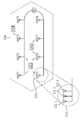
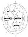
도 2는 다중 노드 시스템의 일 예로 분산 안테나 시스템을 나타낸다.2 shows a distributed antenna system as an example of a multi-node system.
도 2를 참조하면, 분산 안테나 시스템(distributed antenna system, DAS)은 기지국(BS)과 복수의 기지국 안테나들(예컨대, ant 1 내지 ant 8, 이하 기지국 안테나를 안테나로 약칭한다)로 구성된다. 안테나(ant 1 내지 ant 8)들은 기지국(BS)과 유선으로 연결될 수 있다. 분산 안테나 시스템은 종래의 집중 안테나 시스템(centralized antennal system, CAS)과 달리 안테나가 셀(15a)의 특정 지점 예를 들면 셀의 중앙에 몰려 있지 않고 셀 내의 다양한 위치에 분산되어 배치된다. 여기서, 안테나는 도 2에 도시된 바와 같이, 셀 내의 이격된 각 장소에 하나의 안테나가 존재할 수도 있고(안테나 1 내지 안테나 4, 안테나 6 내지 안테나 8), 안테나 5(111)와 같이 여러 개의 안테나들(111-1, 111-2, 111-3)이 밀집되어 존재하는 형태로 분포할 수도 있다. 밀집되어 존재하는 안테나들은 하나의 안테나 노드(antenna node)를 구성할 수 있다.Referring to FIG. 2, a distributed antenna system (DAS) is composed of a base station (BS) and a plurality of base station antennas (e.g.,
안테나들의 안테나 커버리지(coverage)가 오버랩(overlap)되어 랭크(rank) 2 이상의 전송이 가능하게 분포할 수 있다. 예를 들어, 각 안테나의 안테나 커버리지가 인접한 안테나까지 미칠 수 있다. 이 경우, 셀 내에 존재하는 단말들은 셀 내의 위치, 채널 상태 등에 따라 복수의 안테나로부터 수신하는 신호의 강도가 다양하게 변경될 수 있다. 도 2의 예를 참조하면, 단말 1(UE 1)은 안테나 1, 2, 5, 6으로부터 수신 감도가 좋은 신호를 수신할 수 있다. 반면 안테나 3, 4, 7, 8 으로부터 전송되는 신호는 경로 손실(path loss)에 의해 단말 1에게 미치는 영향이 미미할 수 있다.The antenna coverage of the antennas may overlap so that transmission of
단말 2(UE 2)는 안테나 6, 7로부터 수신 감도가 좋은 신호를 수신할 수 있으며 나머지 안테나들로부터 전송되는 신호는 영향이 미미할 수 있다. 마찬가지로 단말 3(UE 3)의 경우, 안테나 3으로부터만 수신 감도가 좋은 신호를 수신할 수 있고 나머지 안테나들의 신호는 무시할 수 있을 만큼 강도가 약할 수 있다.The terminal 2 (UE2) can receive a signal having a good reception sensitivity from the
분산 안테나 시스템에서는 셀 내에서 서로 간에 이격된 단말들에 대해 MIMO 통신을 수행하는 것이 용이할 수 있다. 상기 예에서 단말 1에게는 안테나 1, 2, 5, 6을 통해 통신을 수행하고, 단말 2에게는 안테나 7, 단말 3에게는 안테나 3을 통해 통신을 수행할 수 있다. 안테나 4, 8은 단말 2 또는 단말 3을 위한 신호를 전송할 수도 있고 아무런 신호를 전송하지 않을 수도 있다. 즉, 안테나 4, 8은 경우에 따라 오프 상태로 운용할 수도 있다.In a distributed antenna system, it may be easy to perform MIMO communication for terminals spaced apart from each other in a cell. In the above example, the
상술한 바와 같이 분산 안테나 시스템에서 MIMO 통신을 수행하는 경우, 각 단말 당 레이어(layer, 즉, 전송 스트림의 수)가 다양하게 존재할 수 있다. 또한, 각 단말에 할당되는 안테나(또는 안테나 그룹)가 서로 다를 수 있다. 다시 말해 분산 안테나 시스템에서는 각 단말에 대해 시스템 내의 모든 안테나 중 특정 안테나(또는 특정 안테나 그룹)를 지원할 수 있다. 단말에게 지원하는 안테나는 시간에 따라 변경될 수 있다.As described above, when MIMO communication is performed in the distributed antenna system, there may be various layers per layer (i.e., number of transport streams). In addition, antennas (or antenna groups) allocated to each terminal may be different from each other. In other words, the distributed antenna system can support a specific antenna (or a specific antenna group) among all the antennas in the system for each terminal. The antennas supported by the terminal may be changed over time.
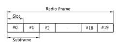
도 3은 3GPP LTE에서 FDD(Frequency Division Duplex) 무선 프레임의 구조를 나타낸다. 이러한 무선 프레임 구조를 프레임 구조 타입 1이라 칭한다. 3 shows the structure of a Frequency Division Duplex (FDD) radio frame in 3GPP LTE. This radio frame structure is referred to as a
도 3을 참조하면, 무선 프레임(radio frame)은 10개의 서브프레임(subframe)으로 구성되고, 하나의 서브프레임은 2개의 연속하는 슬롯(slot)으로 정의된다. 하나의 서브 프레임이 전송되는 데 걸리는 시간을 TTI(transmission time interval)이라 한다. 무선 프레임의 시간 길이 Tf = 307200 * Ts = 10ms이며, 20개의 슬롯으로 구성된다. 슬롯의 시간 길이 Tslot = 15360 * Ts = 0.5ms이며 0에서 19로 넘버링된다. 각 노드 또는 기지국이 단말에게 신호를 전송하는 하향링크와 단말이 각 노드 또는 기지국으로 신호를 전송하는 상향링크는 주파수 영역에서 구분된다.Referring to FIG. 3, a radio frame is composed of 10 subframes, and one subframe is defined as two consecutive slots. The time taken for one subframe to be transmitted is called a transmission time interval (TTI). The time length of the radio frame, Tf = 307200 * Ts = 10 ms, is composed of 20 slots. The time length of theslot is Tslot = 15360 * Ts = 0.5 ms and is numbered from 0 to 19. The downlink in which each node or the base station transmits a signal to the terminal and the uplink in which the terminal transmits signals to each node or the base station are classified in the frequency domain.
도 4는 3GPP LTE에서 TDD(Time Division Duplex) 무선 프레임(radio frame) 구조를 나타낸다. 이러한 무선 프레임 구조를 프레임 구조 타입 2라 칭한다.4 shows a time division duplex (TDD) radio frame structure in 3GPP LTE. This radio frame structure is referred to as a
도 4를 참조하면, 하나의 무선 프레임은 10 ms의 길이를 가지며 5 ms의 길이를 가지는 두 개의 반프레임(half-frame)으로 구성된다. 또한 하나의 반프레임은 1 ms의 길이를 가지는 5개의 서브프레임으로 구성된다. 하나의 서브프레임은 상향링크 서브프레임(UL subframe), 하향링크 서브프레임(DL subframe), 특수 서브프레임(special subframe) 중 어느 하나로 지정된다. 하나의 무선 프레임은 적어도 하나의 상향링크 서브프레임과 적어도 하나의 하향링크 서브프레임을 포함한다. 하나의 서브프레임은 2개의 연속하는 슬롯(slot)으로 정의된다. 예를 들어, 하나의 서브프레임의 길이는 1ms이고, 하나의 슬롯의 길이는 0.5ms 일 수 있다.Referring to FIG. 4, one radio frame is composed of two half-frames having a length of 10 ms and a length of 5 ms. One half frame is composed of five subframes having a length of 1 ms. One subframe is designated as one of a UL subframe, a DL subframe, and a special subframe. One radio frame includes at least one uplink subframe and at least one downlink subframe. One subframe is defined as two consecutive slots. For example, the length of one subframe may be 1 ms and the length of one slot may be 0.5 ms.
특수 서브프레임은 상향링크 서브프레임과 하향링크 서브프레임 사이에서 상향링크 및 하향링크를 분리시키는 특정 구간(period)이다. 하나의 무선 프레임에는 적어도 하나의 특수 서브프레임이 존재하며, 특수 서브프레임은 DwPTS(Downlink Pilot Time Slot), 보호 구간(Guard Period), UpPTS(Uplink Pilot Time Slot)를 포함한다. DwPTS는 초기 셀 탐색, 동기화 또는 채널 추정에 사용된다. UpPTS는 기지국에서의 채널 추정과 단말의 상향 전송 동기를 맞추는 데 사용된다. 보호 구간은 상향링크와 하향링크 사이에 하향링크 신호의 다중경로 지연으로 인해 상향링크에서 생기는 간섭을 제거하기 위한 구간이다.The special subframe is a specific period for separating the uplink and downlink between the uplink subframe and the downlink subframe. At least one special subframe exists in one radio frame, and the special subframe includes a downlink pilot time slot (DwPTS), a guard period, and an uplink pilot time slot (UpPTS). DwPTS is used for initial cell search, synchronization, or channel estimation. UpPTS is used to match the channel estimation at the base station and the uplink transmission synchronization of the terminal. The guard interval is a period for eliminating the interference occurring in the uplink due to the multi-path delay of the downlink signal between the uplink and the downlink.
FDD 및 TDD 무선 프레임에서 하나의 슬롯은 시간 영역(time domain)에서 복수의 OFDM(orthogonal frequency division multiplexing) 심벌을 포함하고, 주파수 영역에서 다수의 자원블록(resource block, RB)을 포함한다. OFDM 심벌은 3GPP LTE가 하향링크에서 OFDMA를 사용하므로 하나의 심벌 구간(symbol period)을 표현하기 위한 것으로, 다중 접속 방식에 따라 SC-FDMA 심벌과 같이 다른 용어로 불릴 수 있다. 자원블록은 자원 할당 단위로 하나의 슬롯에서 복수의 연속하는 부반송파를 포함한다.One slot in an FDD and a TDD radio frame includes a plurality of orthogonal frequency division multiplexing (OFDM) symbols in a time domain and a plurality of resource blocks (RBs) in a frequency domain. The OFDM symbol is used to represent one symbol period since 3GPP LTE uses OFDMA in the downlink and may be called another term such as an SC-FDMA symbol according to the multiple access scheme. A resource block includes a plurality of consecutive subcarriers in one slot in a resource allocation unit.
도 3 및 도 4를 참조하여 설명한 무선 프레임의 구조는 3GPP TS 36.211 V8.3.0 (2008-05) "Technical Specification Group Radio Access Network; Evolved Universal Terrestrial Radio Access (E-UTRA); Physical Channels and Modulation (Release 8)"의 4.1절 및 4. 2절을 참조할 수 있다.The structure of the radio frame described with reference to FIGS. 3 and 4 is described in 3GPP TS 36.211 V8.3.0 (2008-05) " Technical Specification Group Radio Access Network, Evolved Universal Terrestrial Radio Access (E-UTRA) 8) "in Section 4.1 and Section 4.2.
무선 프레임의 구조는 예시에 불과하고, 무선 프레임에 포함되는 서브프레임의 수 또는 서브프레임에 포함되는 슬롯의 수, 슬롯에 포함되는 OFDM 심벌의 수는 다양하게 변경될 수 있다. The structure of the radio frame is merely an example, and the number of subframes included in a radio frame, the number of slots included in a subframe, and the number of OFDM symbols included in a slot can be variously changed.
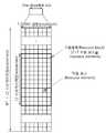
도 5는 하나의 하향링크 슬롯에 대한 자원 그리드(resource grid)를 나타낸 예시도이다.5 is an exemplary diagram illustrating a resource grid for one downlink slot.
도 5를 참조하면, 하나의 하향링크 슬롯은 시간 영역(time domain)에서 복수의 OFDM 심벌을 포함한다. 여기서, 하나의 하향링크 슬롯은 7 OFDMA 심벌을 포함하고, 하나의 자원블록(RB)은 주파수 영역에서 12 부반송파(subcarrier)를 포함하는 것을 예시적으로 기술하나, 이에 제한되는 것은 아니다.Referring to FIG. 5, one downlink slot includes a plurality of OFDM symbols in a time domain. Herein, one downlink slot includes 7 OFDMA symbols and one resource block (RB) includes 12 subcarriers in the frequency domain, but the present invention is not limited thereto.
자원 그리드 상의 각 요소(element)를 자원 요소(resource element)라 하며, 하나의 자원블록(RB)은 12×7개의 자원 요소를 포함한다. 하향링크 슬롯에 포함되는 자원블록의 수 NDL은 셀에서 설정되는 하향링크 전송 대역폭(bandwidth)에 종속한다. 상술한 하향링크 슬롯에 대한 자원 그리드는 상향링크 슬롯에도 적용될 수 있다.Each element on the resource grid is called a resource element, and one resource block (RB) includes 12 × 7 resource elements. The number NDL of resource blocks included in the downlink slot is dependent on the downlink transmission bandwidth set in the cell. The resource grid for the downlink slot described above can also be applied to the uplink slot.
도 6은 하향링크 서브프레임 구조의 일 예를 나타낸다.6 shows an example of a downlink subframe structure.
도 6을 참조하면, 서브프레임은 연속하는 2개의 슬롯을 포함한다. 서브프레임 내의 첫번째 슬롯의 앞선 최대 3 OFDM 심벌들이 하향링크 제어채널들이 할당되는 제어영역(control region)이고, 나머지 OFDM 심벌들은 PDSCH(Physical Downlink Shared Channel)가 할당되는 데이터 영역이 될 수 있다.Referring to FIG. 6, a subframe includes two consecutive slots. A maximum of 3 OFDM symbols preceding a first slot in a subframe may be a control region in which downlink control channels are allocated and a remaining OFDM symbol may be a data region to which a physical downlink shared channel (PDSCH) is allocated.
하향링크 제어채널에는 PCFICH(Physical Control Format Indicator Channel), PDCCH(Physical Downlink Control Channel), PHICH(Physical Hybrid-ARQ Indicator Channel) 등이 포함된다. 서브프레임의 첫번째 OFDM 심벌에서 전송되는 PCFICH는 서브프레임 내에서 제어채널들의 전송에 사용되는 OFDM 심벌의 수(즉, 제어영역의 크기)에 관한 정보를 나른다. PDCCH를 통해 전송되는 제어정보를 하향링크 제어정보(downlink control information, DCI)라고 한다. DCI는 상향링크 자원 할당 정보, 하향링크 자원 할당 정보 및 임의의 UE 그룹들에 대한 상향링크 전송 파워 제어 명령(Transmit Power Control Command) 등을 가리킨다. PHICH는 상향링크 데이터의 HARQ(Hybrid Automatic Repeat Request)에 대한 ACK(Acknowledgement)/NACK(Not-Acknowledgement)신호를 나른다. 즉, 단말이 전송한 상향링크 데이터에 대한 ACK/NACK 신호는 PHICH 상으로 전송된다.The downlink control channel includes a Physical Control Format Indicator Channel (PCFICH), a Physical Downlink Control Channel (PDCCH), and a Physical Hybrid-ARQ Indicator Channel (PHICH). The PCFICH transmitted in the first OFDM symbol of the subframe carries information on the number of OFDM symbols (i.e., the size of the control region) used for transmission of the control channels in the subframe. The control information transmitted through the PDCCH is referred to as downlink control information (DCI). DCI indicates uplink resource allocation information, downlink resource allocation information, and uplink transmission power control commands for arbitrary UE groups. The PHICH carries an ACK (Acknowledgment) / NACK (Not-Acknowledgment) signal for HARQ (Hybrid Automatic Repeat Request) of the uplink data. That is, the ACK / NACK signal for the uplink data transmitted by the UE is transmitted on the PHICH.
PDSCH는 제어 정보 및/또는 데이터가 전송되는 채널이다. 단말은 PDCCH를 통해 전송되는 하향링크 제어정보를 디코딩하여 PDSCH를 통해 전송되는 데이터를 읽을 수 있다.The PDSCH is a channel through which control information and / or data is transmitted. The UE can decode the downlink control information transmitted through the PDCCH and read the data transmitted through the PDSCH.
이하에서, 다중 노드 시스템에서 참조 신호 전송 방법에 대해 설명한다. 설명의 편의를 위해 기존 기지국의 참조 신호 전송 방법에 대해 먼저 설명한다. LTE Rel-8에서는 채널 측정과 PDSCH에 대한 채널 추정을 위해 CRS(cell specific reference signal)을 사용한다.Hereinafter, a method of transmitting a reference signal in a multi-node system will be described. For convenience of description, a reference signal transmission method of an existing base station will be described first. LTE Rel-8 uses CRS (cell specific reference signal) for channel measurement and channel estimation for PDSCH.
도 7은 노멀 CP에서 CRS의 맵핑을 나타내다. 도 8은 확장 CP에서 CRS의 맵핑을 나타낸다.Figure 7 shows the mapping of the CRS in the normal CP. Figure 8 shows the mapping of the CRS in the extended CP.
도 7 및 도 8을 참조하면, 복수의 안테나를 사용하는 다중 안테나 전송의 경우, 각 안테나마다 자원 그리드가 존재하며 각 안테나를 위한 적어도 하나의 참조신호가 각각의 자원 그리드에 맵핑될 수 있다. 각 안테나별 참조신호는 참조심벌들로 구성된다. Rp는 안테나 포트 p의 참조심벌을 나타낸다(p ∈{0, 1, 2, 3}). R0 내지 R3은 서로 중복되는 자원요소에 맵핑되지 않는다.Referring to FIGS. 7 and 8, in the case of multiple antenna transmission using a plurality of antennas, a resource grid exists for each antenna, and at least one reference signal for each antenna may be mapped to each resource grid. The reference signal for each antenna consists of reference symbols. Rp represents the reference symbol of antenna port p (p ∈ {0, 1, 2, 3}). R0 to R3 are not mapped to overlapping resource elements.
하나의 OFDM 심벌에서 각 Rp는 6 부반송파 간격으로 위치할 수 있다. 서브프레임 내 R0의 수와 R1의 수는 동일하고, R2의 수와 R3의 수는 동일하다. 서브프레임 내 R2, R3의 수는 R0, R1의 수보다 적다. Rp는 안테나 포트 p를 제외한 다른 안테나 포트를 통해서는 어떤 전송에도 사용되지 않는다.In one OFDM symbol, each Rp may be located at six subcarrier spacing. The number of R0 and the number of R1 in the subframe are the same, and the number of R2 and the number of R3 are the same. The number of R2, R3 in the subframe is less than the number of R0, R1. Rp is not used for any transmission through any other antenna port except antenna port p.
LTE-A에서는 채널 측정, PDSCH에 대한 채널 추정을 위해 CRS와 별도로 CSI-RS(channel status information reference signal)이 사용될 수 있다. 이하, CSI-RS에 대해 설명한다.In the LTE-A, a channel status information reference signal (CSI-RS) may be used separately from the CRS for channel measurement and channel estimation for the PDSCH. Hereinafter, the CSI-RS will be described.
CSI-RS는 CRS와 달리 이종 네트워크 환경을 포함하는 다중 셀 환경에서 셀 간 간섭(inter-cell interference, ICI)을 줄이기 위해 최대 32가지 서로 다른 설정이 존재한다.Unlike CRS, CSI-RS has up to 32 different settings to reduce inter-cell interference (ICI) in multi-cell environments including heterogeneous network environments.
CSI-RS에 대한 설정은 셀 내의 안테나 포트 수에 따라 서로 다르며, 인접 셀간에 최대한 서로 다른 설정이 되도록 주어진다. CSI-RS는 CP 타입에 따라 구분되며, 프레임 구조 타입(프레임 구조 타입 1은 FDD, 프레임 구조 타입 2는 TDD)에 따라 프레임 구조 타입 1, 프레임 구조 타입 2에 모두 적용되는 설정과, 프레임 구조 타입 2에만 적용되는 설정으로 구분된다.The setting for the CSI-RS differs depending on the number of antenna ports in the cell, and is given to be as different as possible among adjacent cells. The CSI-RS is classified according to the CP type. The CSI-RS is configured to apply both the
CSI-RS는 CRS와 달리 최대 8 안테나 포트까지 지원하며, 안테나 포트 p는 {15}, {15, 16}, {15,16,17,18}, {15, ..., 22}가 지원된다. 즉, 1개, 2개, 4개, 8개의 안테나 포트를 지원한다. 부반송파 간의 간격 Δf는 15kHz에 대해서만 정의된다.Unlike CRS, CSI-RS supports up to 8 antenna ports, and antenna port p is supported by {15}, {15, 16}, {15,16,17,18}, {15, ..., 22} do. That is, it supports one, two, four, and eight antenna ports. The spacing? F between subcarriers is defined only for 15 kHz.
CSI-RS에 대한 참조 신호 시퀀스 rl,ns(m)은 다음 식과 같이 생성된다.The reference signal sequence rl, ns (m) for the CSI-RS is generated as shown in the following equation.
[식 1][Formula 1]

상기 식 1에서 ns는 무선 프레임 내에서 슬롯 넘버이고, l은 슬롯 내에서의 OFDM 심벌 넘버이다. c(i)는 의사 랜덤 시퀀스(pseudo random sequence)이며 cinit로 각 OFDM 심벌에서 시작된다. NIDcell은 물리 계층 셀 ID를 의미한다.In Equation (1), ns is a slot number in a radio frame, and l is an OFDM symbol number in a slot. c (i) is a pseudo-random sequence and starts in each OFDM symbol with cinit . NIDcell denotes a physical layer cell ID.
CSI-RS를 전송하도록 설정된 서브프레임들에서, 참조 신호 시퀀스 rl,ns(m)는 안테나 포트 p에 대한 참조 심벌로 사용되는 복소값 변조 심벌 ak,l(p)에 맵핑된다.In the subframes set to transmit CSI-RS, the reference signal sequence rl, ns (m) is mapped to a complex-valued modulation symbol ak, l(p) used as a reference symbol for antenna port p.
rl,ns(m)와 ak,l(p)의 관계는 다음 식과 같다.The relation between rl, n s (m) and ak, l(p) is as follows.
[식 2][Formula 2]

상기 식 2에서 (k’, l’)과 ns는 후술하는 표 1 및 표 2에서 주어진다. CSI-RS는 (ns mod 2)가 후술하는 표 1 및 표 2의 조건을 만족하는 하향링크 슬롯에서 전송될 수 있다(mod는 모듈러 연산을 의미한다. 즉, ns 를 2로 나눈 나머지를 의미한다).(K ', l') and ns in the
다음 표는 노멀 CP에 대한 CSI-RS 설정을 나타낸다.The following table shows the CSI-RS settings for the normal CP.
[표 1][Table 1]

다음 표는 확장 CP에 대한 CSI-RS 설정을 나타낸다.The following table shows the CSI-RS settings for the extended CPs.
[표 2][Table 2]

또한, CSI-RS는 다음 표 3의 조건을 만족하는 서브프레임에서 전송될 수 있다.In addition, the CSI-RS can be transmitted in a subframe satisfying the conditions of Table 3 below.
즉, CSI-RS를 포함하는 서브프레임은 다음 식을 만족해야 한다.That is, the subframe including the CSI-RS must satisfy the following equation.
[식 3][Formula 3]

식 3에서 TCSI-RS는 CSI-RS의 셀 특정적인 주기(period)를 나타낸다. ΔCSI-RS는 CSI-RS의 셀 특정적 서브프레임 오프셋을 나타낸다. nf는 시스템 프레임 넘버를 나타낸다.In
다음 표 3은 CSI-RS의 주기 및 전송 시점과 관련된 CSI-RS 서브프레임 설정을 나타낸다.Table 3 below shows CSI-RS subframe settings related to CSI-RS period and transmission time.
[표 3][Table 3]

상기 표 3에서 ‘CSI-RS-SubframeConfig’즉, ICSI-RS는 상위 계층에 의해 주어지는 값으로 CSI-RS 서브프레임 설정 넘버를 나타낸다. 즉, CSI-RS는 CSI-RS 서브프레임 설정 넘버에 따라 CSI-RS 주기(TCSI-RS)와 CSI-RS 서브프레임 오프셋(ΔCSI-RS)가 결정된다. CSI-RS는 CQI/CSI 피드백에 따라 5가지 CSI-RS 주기를 지원하며, 각 셀에서 서로 다른 CSI-RS 서브프레임 오프셋을 가지고 전송될 수 있다.In Table 3, 'CSI-RS-SubframeConfig', that is, ICSI-RS indicates a CSI-RS subframe setting number with a value given by an upper layer. That is, CSI-RS is a CSI-RS period (TCSI-RS) and a CSI-RS subframe offset (ΔCSI-RS) is determined according to the CSI-RS subframe set number. The CSI-RS supports five CSI-RS periods according to CQI / CSI feedback, and can be transmitted with different CSI-RS subframe offset in each cell.
도 9는 노멀 CP에서 CSI 설정 넘버 0에 대한 CSI-RS의 맵핑을 나타내고, 도 10은 확장 CP에서 CSI 설정 넘버 0에 대한 CSI-RS의 맵핑을 나타낸다.FIG. 9 shows a mapping of the CSI-RS to the
도 9 및 도 10을 참조하면, 2개의 안테나 포트 예를 들어, p = {15, 16}, {17, 18}, {19, 20}, {21, 22}에 대해 연속하는 2개의 동일한 자원요소를 사용하여 CSI-RS를 전송하되, 서로 다른 OCC(orthogonal cover code)를 사용하여 전송한다. 즉, 2개의 안테나 포트에 대하여 동일한 자원요소를 이용하여 CSI-RS를 전송하되, 각 안테나 포트에 대한 CSI-RS는 OCC를 통해 구분된다.9 and 10, two consecutive identical resources for two antenna ports, for example p = {15,16}, {17,18}, {19,20}, {21,22} Element to transmit CSI-RS, but using a different OCC (orthogonal cover code). That is, CSI-RS is transmitted using the same resource element for two antenna ports, and CSI-RS for each antenna port is divided through OCC.
복수의 CSI-RS 설정이 주어진 셀에서 사용 가능한데, 단말이 넌 제로(non-zero) 전송 전력을 가정하는 하나의 CSI-RS 설정과 단말이 제로(zero) 전송 전력을 가정하는 CSI-RS설정을 하나 이상 또는 없도록 설정할 수 있다.A plurality of CSI-RS settings can be used in a given cell. A CSI-RS configuration in which the UE assumes a non-zero transmission power and a CSI-RS configuration in which the UE assumes a zero transmission power You can set up more than one or none.
CSI-RS는 다음 경우에 전송되지 않는다.The CSI-RS is not transmitted in the following cases.
1. 프레임 구조 타입 2의 특별 서브프레임(special subframe).1. Special subframe of
2. 동기화 신호, PBCH(physical broadcast channel), SIB(system information block)와 충돌될 경우.2. In case of conflict with synchronization signal, physical broadcast channel (PBCH), system information block (SIB).
3. 페이징 메시지(paging message)가 전송되는 서브프레임.3. The subframe where the paging message is transmitted.
집합 S의 임의의 안테나 포트에 대한 CSI-RS의 전송에 사용되는 자원 요소 (k,l)은 동일 슬롯에서 임의의 안테나 포트에 대한 PDSCH의 전송에 사용되지 않는다. 여기서, 집합 S에 포함되는 안테나 포트는 {15,16}, {17,18}, {19,20}, {21, 22}이다. 또한, 상기 자원 요소 (k,l)은 동일 슬롯에서 상기 집합 S에 포함된 안테나 포트를 제외한 다른 임의의 안테나 포트에 대한 CSI-RS 전송에 사용되지 않는다.The resource element (k, l) used for transmission of the CSI-RS to an arbitrary antenna port of the set S is not used for transmission of the PDSCH for an arbitrary antenna port in the same slot. Here, the antenna ports included in the set S are {15,16}, {17,18}, {19,20}, {21, 22}. Also, the resource element (k, l) is not used for CSI-RS transmission to any other antenna port except the antenna port included in the set S in the same slot.
이러한 CSI-RS의 전송에 필요한 파라미터들은 1. CSI-RS 포트 수(number of CSI-RS ports), 2. CSI-RS 설정을 나타내는 CSI-RS 설정 넘버(CSI-RS configuration number), 3. CSI-RS의 전송 주기 및 시점을 지시하는 CSI-RS 서브프레임 설정 넘버(ICSI-RS) 등이며 이러한 파라미터들은 셀 혹은 단말 특정적이고 상위 계층(higher layer) 시그널링을 통해 주어질 수 있다. 상술한 CRS, CSI-RS와 같은 참조 신호는 다중 노드 시스템에서 단말이 각 노드를 식별할 수 있도록 적용될 수 있다.
The parameters necessary for transmission of the CSI-RS include: 1. number of CSI-RS ports; 2. CSI-RS configuration number indicating CSI-RS configuration; 3. CSI- A CSI-RS subframe setup number (ICSI-RS ) indicating the transmission period and time of theRS , and these parameters may be given through cell or UE-specific and higher layer signaling. Reference signals such as the CRS and the CSI-RS described above can be applied so that the UE can identify each node in a multi-node system.
이하에서, 가상 셀을 포함하는 다중 노드 시스템에서 단말이 가상 셀로부터 신호를 수신하는 방법 및 장치에 대해 설명한다.Hereinafter, a method and apparatus for a terminal to receive a signal from a virtual cell in a multi-node system including a virtual cell will be described.
도 11은 가상 셀을 포함하는 다중 노드 시스템을 예시한다.11 illustrates a multi-node system including a virtual cell.
도 11을 참조하면, 다중 노드 시스템은 하나의 기지국(미도시)에 연결된 복수의 노드(111 내지 116)가 존재한다. 복수의 노드는 분산되어 배치된다. 노드의 예는 RRH(remote radio head), RRU(remote radio unit), 액세스 포인트, 안테나, 안테나 노드, 안테나 그룹 등일 수 있다. 다중 노드 시스템을 효율적으로 운용하기 위해서는 복수의 노드가 하나의 셀로 동작하면서, 동시에 가상 셀(virtual cell)로 동작하는 것이 바람직하다.Referring to FIG. 11, a multi-node system includes a plurality of
여기서, 가상 셀이란 레거시 단말(legacy UE)에게는 독립적인 셀 또는 안테나로 인식되지 않으나, 개선된 단말(advanced UE)에게는 독립적인 셀 또는 안테나로 인식되는 셀을 의미한다. 예컨대, 3GPP LTE에 의하여 동작하는 단말은 레거시 단말일 수 있고, LTE-A에 의하여 동작하는 단말은 개선된 단말일 수 있다. 레거시 단말이 인식하는 셀을 머더 셀(mother cell)이라 칭한다. 도 11에서 셀 A(Cell A)가 머더 셀일 수 있다. 머더 셀은 기지국이 지원하는 셀일 수 있다. 개선된 단말은 머더 셀 및 가상 셀을 모두 인식할 수 있다.Here, a virtual cell means a cell that is not recognized as an independent cell or an antenna for a legacy UE but is recognized as an independent cell or an antenna for an advanced UE. For example, a terminal operating by 3GPP LTE may be a legacy terminal, and a terminal operating by LTE-A may be an improved terminal. A cell recognized by a legacy terminal is called a mother cell. In Fig. 11, cell A (Cell A) may be a mother cell. The mother cell may be a cell supported by the base station. The enhanced terminal can recognize both the mother cell and the virtual cell.
가상 셀로 동작하는 노드는 머더 셀의 셀 ID에 기반한 동기화 신호(synchronization signal, SS)를 전송한다. 또한, 가상 셀로 동작하는 노드는 개선된 단말이 인지할 수 있는 가상 셀 특정적 신호를 전송한다. 가상 셀 특정적 신호는 예를 들어, 파일럿 신호(예를 들면, CSI-RS, 또는 PRS(positioning reference signal) 등)나 레거시 단말이 인지하지 못하는 새로운 동기화 신호일 수 있다.A node operating as a virtual cell transmits a synchronization signal (SS) based on the cell ID of the mother cell. In addition, a node operating as a virtual cell transmits a virtual cell specific signal that can be recognized by the enhanced terminal. The virtual cell specific signal may be, for example, a pilot signal (e.g., CSI-RS, or positioning reference signal (PRS)) or a new synchronization signal that the legacy terminal does not recognize.
개선된 단말은 가상 셀들을 CoMP(Coordinated Multi-Point), eICIC(enhanced Inter-Cell Interference Coordination) 등과 같은 셀 간 협력 통신에서의 협력 셀로 인식하거나, 안테나간 협력전송, 즉 MIMO(Multi Input Multi Output)전송을 수행하는 셀 내의 안테나(포트)로 인식할 수 있다.The enhanced terminal recognizes virtual cells as cooperative cells in inter-cell cooperative communication such as Coordinated Multi-Point (CoMP) and enhanced Inter-Cell Interference Coordination (eICIC), or performs cooperative transmission between antennas, i.e., Multi Input Multi Output (MIMO) It can be recognized as an antenna (port) in a cell performing transmission.
가상 셀을 포함하는 다중 노드 시스템은, 셀의 중심에 높은 전송 전력을 갖는 노드가 셀 전체를 커버하는 머더 셀을 형성하고, 머더 셀 내에서 낮은 전송 전력을 갖는 노드들이 가상 셀들을 형성하는 형태로 구현될 수 있다. 또는 셀 내의 모든 노드가 동일한 신호를 전송하는 방식으로 하나의 머더 셀을 형성하고, 머더 셀 내의 낮은 전송 전력을 갖는 노드들이 가상 셀들을 형성하는 형태로 구현될 수도 있다. 또는 낮은 전송 전력을 갖는 노드들이 각각 하나의 가상 셀을 형성하되, 인접한 복수의 노드들이 함께 하나의 가상 셀을 형성할 수도 있다.In a multi-node system including a virtual cell, a node having a high transmission power at the center of the cell forms a mother cell covering the entire cell, and nodes having low transmission power in the mother cell form virtual cells Can be implemented. Or all nodes in a cell form one mother cell in such a manner that the same signal is transmitted, and nodes having low transmission power in the mother cell form virtual cells. Alternatively, nodes having low transmission power may form one virtual cell, and adjacent nodes may form one virtual cell together.
이하 가상 셀을 포함하는 다중 노드 시스템을 가상 셀 시스템이라 칭한다. 가상 셀 시스템에서 개선된 단말이 가상 셀 특정적 신호를 인식하기 위해서는 머더 셀 내의 가상 셀들의 특성을 알고 있는 것이 바람직하다. 만약 개선된 단말이 가상 셀의 특성을 전혀 알지 못한다면, 단말은 가상 셀 특정적 신호에 대한 모든 파라미터에 대해 블라인드 검출을 수행해야 한다. 블라인드 검출이란, 각 전송 파라미터를 특정 값으로 가정하고 디코딩을 수행한 후, 오류가 검출되지 않으면 바르게 디코딩이 된 것으로 판단하는 것을 의미한다. 따라서, 블라인드 검출은 단말에게 높은 계산 능력을 요구하며 전력 소모를 증가시킨다.Hereinafter, a multi-node system including a virtual cell is referred to as a virtual cell system. In order to recognize a virtual cell-specific signal in an improved terminal in a virtual cell system, it is desirable to know characteristics of virtual cells in a mother cell. If the enhanced terminal does not know the characteristics of the virtual cell at all, the terminal must perform blind detection on all parameters for the virtual cell specific signal. The blind detection means that decoding is performed assuming that each transmission parameter is a specific value, and then, if no error is detected, it is determined that decoding has been correctly performed. Thus, blind detection requires high computational power to the terminal and increases power consumption.
가상 셀 특정적 신호에 대한 파라미터는 가상 셀 특정적 신호가 사용하는 셀 ID, 안테나 포트의 개수, 안테나 포트 넘버, 참조 신호 설정 넘버, 참조 신호 서브프레임 설정 넘버 등 다양하다. 단말이 이러한 다양한 파라미터에 대한 블라인드 검출을 수행하는 것은 전력 소모를 증가시키므로 바람직하지 않다.The parameters for the virtual cell specific signal include a cell ID used by the virtual cell specific signal, the number of antenna ports, an antenna port number, a reference signal setting number, and a reference signal subframe setting number. Performing blind detection on these various parameters of the terminal is undesirable because it increases power consumption.
이러한 문제를 해결하기 위해 기지국은 개선된 단말에게 머더 셀 내의 가상 셀 특정적인 신호들에 대한 파라미터 정보를 모두 알려줄 수 있다. 즉, 머더 셀은 단말에게 가상 셀들에 대한 셀 ID, 안테나 포트의 개수, 안테나 포트 넘버, 참조 신호 설정 넘버, 참조 신호 서브프레임 설정 넘버와 같은 파라미터들을 알려줄 수 있다.To solve this problem, the base station can inform the improved terminal of all the parameter information about the virtual cell-specific signals in the cell. That is, the user cell can inform the UE of parameters such as a cell ID for virtual cells, the number of antenna ports, an antenna port number, a reference signal setting number, and a reference signal subframe setting number.
가상 셀 특정적인 파라미터는 예를 들어, RRC(radio resource control) 메시지와 같은 상위 계층 신호를 통해 전송될 수 있다. 즉, 가상 셀 특정적인 파라미터는 RRC의 새로운 IE(information element)로 정의하여 알려주거나, 기존 IE에 포함하여 알려줄 수 있다. 예컨대, LTE에서는 가상 셀의 셀 ID를 이웃 셀 리스트(neighbour cell list) 에 포함하여 알려주고, ‘NeighCellConfig IE’에 가상 셀에 대한 CSI-RS 설정 넘버, 안테나 포트의 개수 등의 정보를 추가하여 전송할 수 있다. 혹은 가상 셀 특정적인 파라미터 중 일부를 ‘CSI-RS-Config IE’에 포함하여 단말에게 알려줄 수 있다.The virtual cell specific parameters may be transmitted via an upper layer signal such as, for example, a radio resource control (RRC) message. That is, the virtual cell specific parameter can be defined as a new information element (IE) of the RRC or informed by including it in the existing IE. For example, in LTE, a cell ID of a virtual cell is reported in a neighbor cell list, and information such as a CSI-RS setting number and an antenna port number for a virtual cell is added to 'NeighCellConfig IE' have. Or some of the virtual cell-specific parameters in the 'CSI-RS-Config IE'.
다음 표는 CSI-RS-Config IE의 일 예이다.The following table is an example of the CSI-RS-Config IE.
[표 4][Table 4]

상기 표 4에서, ‘antennaPortsCount’는 CSI-RS의 전송에 사용되는 안테나 포트의 개수를 나타낸다. ‘resourceConfig’는 CSI-RS 설정을 나타내는 파라미터이고, ‘subframeConfig’는 ICSI-RS를 지시한다. ‘zeroTxPowerResourceConfigList’및 ‘zeroTxPowerSubframeConfig’는 영 전송 전력을 가지는 CSI-RS의 설정에 관련된 파라미터이다. 이러한 CSI-RS-Config IE에 가상 셀 특정적인 파라미터를 포함하여 전송할 수 있다. 예를 들어, 총 ‘antennaPortsCount’ 개의 CSI-RS 포트들을 몇 개의 가상 셀들이 어떤 방식으로 나누어 전송할 지에 대한 정보를 ‘CSI-RS-Config IE’에 포함할 수 있다. 즉, 동일한 CSI-RS 설정을 나누어 사용하는 가상 셀의 수 및/또는 가상 셀들과 CSI-RS 포트 넘버간의 맵핑정보를 포함할 수 있다.In Table 4, 'antennaPortsCount' represents the number of antenna ports used for CSI-RS transmission. 'resourceConfig' is a parameter indicating CSI-RS setting, and 'subframeConfig' indicates ICSI-RS . 'zeroTxPowerResourceConfigList' and 'zeroTxPowerSubframeConfig' are parameters related to the setting of CSI-RS having zero transmission power. The CSI-RS-Config IE can be transmitted by including the virtual cell-specific parameters. For example, the 'CSI-RS-Config IE' can include information on how several virtual cells are divided and transmitted to the total 'antennaPortsCount' CSI-RS ports. That is, it may include the number of virtual cells used by dividing the same CSI-RS configuration and / or mapping information between virtual cells and a CSI-RS port number.
상술한 바와 같이 머더 셀이 가상 셀 특정적 신호에 대한 파라미터들 즉, 설정 정보를 단말에게 모두 알려준다면, 가상 셀이 다수 존재하거나 추가해야 하는 파라미터 수가 많은 경우 시그널링 오버헤드(signaling overhead)가 지나치게 증가할 수 있다.As described above, if the mother cell informs the UE of the parameters for the virtual cell specific signal, that is, the configuration information, if there are many virtual cells or a large number of parameters to be added, the signaling overhead is excessively increased can do.
또한, 단말은 가상 셀 특정적 신호에 대한 L2 및/또는 L3 측정 값(예를 들어, CQI(channel quality indicator), RSRP(reference signal received power), RSRQ(reference signal received quality))과 함께 측정된 가상 셀에 대한 파라미터(예를 들어, 셀 ID, 안테나 포트 넘버, 참조 신호 설정 넘버)를 함께 피드백해야 할 수 있다. 이 때, 가상 셀의 파라미터 후보의 범위가 증가할수록 피드백 시그널링 오버헤드도 증가하는 문제가 있다.In addition, the UE may measure the L2 and / or L3 measurements (e.g., channel quality indicator (CQI), reference signal received power (RSRP), and reference signal received quality (RSRQ) Parameters (e.g., cell ID, antenna port number, reference signal setting number) for the virtual cell may be fed back together. At this time, there is a problem that the feedback signaling overhead increases as the range of parameter candidates of the virtual cell increases.
따라서, 가상 셀에 대한 파라미터를 시그널링 오버헤드의 과도한 증가를 방지하면서 단말에게 알려줌으로써 효율적으로 단말이 가상 셀의 신호를 수신할 수 있는 방법 및 장치가 필요하다.Accordingly, there is a need for a method and apparatus that can efficiently receive a signal of a virtual cell by notifying a terminal of a parameter for a virtual cell while preventing an excessive increase in signaling overhead.
가상 셀 파라미터는 가상 셀 별로 서로 다른 값을 가질 수 있는 파라미터 즉, 가상 셀 특정적인 파라미터이다. 가상 셀 파라미터는 예를 들어, 가상 셀의 셀 ID, 안테나 포트의 개수, 안테나 포트 넘버, 참조 신호 설정 정보(예를 들면, CSI-RS 설정 넘버, CSI-RS 서브프레임 설정 넘버) 등일 수 있다. 이러한 가상 셀 파라미터는 머더 셀의 파라미터에 종속적으로 결정될 수 있다. 예컨대, 가상 셀의 안테나 포트의 개수는 머더 셀의 안테나 포트의 개수와 동일할 수 있다. 그러면, 가상 셀에 대한 안테나 포트의 개수는 가상 셀 특정적 파라미터를 전송할 때 생략될 수 있다. 또는 단말이 가상 셀 특정적 신호를 블라인드 검출할 때 가상 셀에 대한 안테나 포트의 개수는 머더 셀의 파라미터를 통해 이미 알고 있으므로 검출 오버헤드를 줄일 수 있다.The virtual cell parameter is a parameter that can have a different value for each virtual cell, that is, a virtual cell-specific parameter. The virtual cell parameter may be, for example, a cell ID of a virtual cell, a number of antenna ports, an antenna port number, reference signal setting information (e.g., a CSI-RS setting number, a CSI-RS subframe setting number) This virtual cell parameter may be determined depending on the parameters of the mother cell. For example, the number of antenna ports of a virtual cell may be equal to the number of antenna ports of a mother cell. Then, the number of antenna ports for a virtual cell may be omitted when transmitting a virtual cell specific parameter. Or when the terminal blindly detects a virtual cell specific signal, the number of antenna ports for the virtual cell is already known through the parameters of the mother cell, so that the detection overhead can be reduced.
단말이 가상 셀 파라미터를 머더 셀의 파라미터를 기반으로 알 수 있다면, 가상 셀 시스템의 시그널링 오버헤드를 낮추고, 단말이 가상 셀 특정적 신호를 블라인드 검출할 때, 계산 속도를 높이고 전력 소모를 낮출 수 있는 장점이 있다.If the terminal can know the virtual cell parameters based on the parameters of the mother cell, it is possible to lower the signaling overhead of the virtual cell system and to increase the calculation speed and reduce the power consumption when the terminal blindly detects the virtual cell- There are advantages.
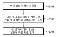
도 12는 본 발명의 일 실시예에 따른, 단말이 가상 셀의 신호를 수신하는 방법을 나타낸다.12 illustrates a method for a terminal to receive a signal of a virtual cell, according to an embodiment of the present invention.
도 12를 참조하면, 단말은 머더 셀의 파라미터를 획득한다(S101). 예를 들어, 단말은 머더 셀 특정적인 브로드캐스트(broadcast) 메시지 또는 신호를 이용하여 머더 셀의 파라미터를 획득할 수 있다. 머더 셀 특정적인 브로드캐스트 메시지 또는 신호에는 예를 들어, 시스템 정보 블록(SIB), 동기화 신호, CRS(cell-specific reference signal) 등이 있다.Referring to FIG. 12, the terminal acquires parameters of a mother cell (S101). For example, the terminal may acquire the parameters of the mother cell using a mother cell specific broadcast message or signal. A specific broadcast message or signal includes, for example, a system information block (SIB), a synchronization signal, and a cell-specific reference signal (CRS).
단말은 머더 셀의 파라미터를 기반으로 가상 셀 파라미터 후보의 범위를 결정한다(S102).The terminal determines the range of the virtual cell parameter candidate based on the parameters of the mother cell (S102).
단말은 가상 셀 파라미터 후보의 범위에 따른 자원을 탐색하여 가상 셀 특정적 신호를 수신한다(S103).The terminal searches for a resource according to the range of the virtual cell parameter candidate and receives a virtual cell specific signal (S103).
여기서는 가상 셀 파라미터를 머더 셀의 파라미터를 기반으로 결정하는 예를 설명하였으나, 이는 제한이 아니다. 즉, 가상 셀 파라미터는 기준 파라미터에 기반하여 결정될 수 있다. 기준 파라미터란 기지국이 단말에게 지정하거나 표준으로 약속된 특정 값, 머더 셀의 파라미터 값 등이 될 수 있다. 즉, 도 12는 기준 파라미터의 일 예로 머더 셀의 파라미터인 경우를 설명하고 있다.Although an example of determining a virtual cell parameter based on a parameter of a mother cell has been described here, this is not a limitation. That is, the virtual cell parameter can be determined based on the reference parameter. The reference parameter may be a specific value assigned to the terminal by the base station or promised as a standard, a parameter value of a mother cell, and the like. That is, FIG. 12 explains the case of a parameter of a mother cell as an example of a reference parameter.
가상 셀 특정적 신호는 예를 들어, 가상 셀이 전송하는 CSI-RS일 수 있다. 그러면, 가상 셀 파라미터는 가상 셀이 전송하는 CSI-RS에 대한 CSI-RS 설정 넘버, CSI-RS 서브프레임 설정 넘버 등이 될 수 있다. 또한, 기준 파라미터는 예를 들어, 기지국이 개선된 단말에게 지정하는 영-전력(zero-power) CSI-RS의 파라미터일 수 있다. 개선된 단말에게 전송하는 가상 셀 특정적인 CSI-RS는 영-전력 CSI-RS의 파라미터가 지정하는 자원 요소에서 전송될 수 있기 때문이다.The virtual cell specific signal may be, for example, the CSI-RS transmitted by the virtual cell. Then, the virtual cell parameter may be a CSI-RS setting number for the CSI-RS transmitted by the virtual cell, a CSI-RS subframe setting number, and the like. Also, the reference parameter may be, for example, a parameter of a zero-power CSI-RS that the base station assigns to the enhanced terminal. Since the virtual cell specific CSI-RS to transmit to the enhanced terminal can be transmitted in the resource element specified by the parameter of the zero-power CSI-RS.
이처럼 가상 셀 특정적 신호에 대한 일부 가상 셀 파라미터는 알고 나머지 가상 셀 파라미터는 모르는 상태에서 블라인드 검출을 수행하는 것을 세미 블라인드 검출(semi-blind detection, SBD)이라 칭할 수 있다.Such blind detection can be referred to as semi-blind detection (SBD) in such a way that some of the virtual cell parameters for the virtual cell specific signal are known and the remaining virtual cell parameters are unknown.
이러한 SBD 방법에 의할 때, 적어도 2가지 장점이 있다. 첫째는 단말이 가상 셀 특정적 신호를 더 낮은 검색 오버헤드를 가지면서 검출할 수 있고, 둘째는 단말의 계산 속도 요구량 및 전력 소모가 감소된다.There are at least two advantages to this SBD approach. First, the terminal can detect a virtual cell specific signal with a lower search overhead, and secondly, the computation speed requirement and power consumption of the terminal are reduced.
이하에서는 기준 파라미터(예를 들면, 머더 셀의 파라미터)를 기반으로 가상 셀 파라미터를 결정하는 방법에 대해 설명한다. 이하에서, 가상 셀 파라미터의 예로 가상 셀의 셀 ID, CSI-RS 설정 정보 등을 설명하나 이에 한정되는 것은 아니다.Hereinafter, a method for determining a virtual cell parameter based on a reference parameter (for example, a parameter of a mother cell) will be described. Hereinafter, the cell ID of the virtual cell, the CSI-RS setting information, and the like will be described as an example of the virtual cell parameter, but the present invention is not limited thereto.
<실시예 1 : 가상 셀의 셀 ID>≪ Embodiment 1: Cell ID of virtual cell >
가상 셀 특정적 신호가 서로 다른 셀 ID를 사용하는 경우를 가정한다. 머더 셀의 셀 ID의 가능한 총 개수(이를 후보라 칭함)는 시스템에 따라 결정될 수 있다. 예를 들어, LTE의 경우 머더 셀의 셀 ID의 후보는 504개, IEEE 802.16의 경우에는 768개일 수 있다. 셀 ID를 표현하기 위한 정보량을 비트로 환산하면, LTE의 경우 9비트, IEEE 802. 16의 경우 10비트가 된다. 이 때, 가상 셀의 셀 ID가 머더 셀의 셀 ID와 일부 비트가 동일하도록 규정한다면, 가상 셀의 셀 ID를 전달하기 위한 정보량이 줄어들게 된다.It is assumed that the virtual cell specific signals use different cell IDs. The total number of possible cell IDs of the mother cells (hereinafter referred to as the latter) may be determined according to the system. For example, in the case of LTE, 504 candidates for the cell ID of the mother cell and 768 for the IEEE 802.16 cell. If the amount of information for representing the cell ID is converted into bits, it is 9 bits for LTE and 10 bits for IEEE 802.16. At this time, if the cell ID of the virtual cell is defined to be the same as the cell ID of the mother cell, the amount of information for transmitting the cell ID of the virtual cell is reduced.
예를 들어, 가상 셀이 전송하는 동기화 신호에서 셀 ID를 구성하는 시드 넘버 중 일부를 머더 셀의 셀 ID를 구성하는 시드 넘버와 동일하게 규정할 수도 있다. 예컨대, LTE에서 셀 ID(NIDcell)는 NIDcell = 3 NID(1) + NID(2)와 같이 구성된다. 여기서, NID(1)는 셀 ID 그룹을 나타내며, 0 에서 167 중 어느 하나의 값일 수 있다. NID(2)는 셀 ID 그룹 내의 셀 ID를 나타내며 0 내지 2 중 어느 하나의 값일 수 있다. 이 때, NID(1)는 8비트로 표현되고, NID(2)는 2비트로 표현된다. 동일한 머더 셀 내에 존재하는 가상 셀들에게 할당되는 셀 ID는 상술한 NID(1) 및/또는 NID(2)중 일부 비트가 동일하도록 규정할 수 있다. 예를 들어, 동일 기지국에 연결된 모든 노드들은 동일한 NID(1) 을 가질 수 있다. 그러면, 각 노드는 NID(2)에 의해 구분될 수 있다.For example, some of the seed numbers constituting the cell ID in the synchronization signal transmitted by the virtual cell may be defined to be the same as the seed number constituting the cell ID of the cell. For example, in LTE, a cell ID (NIDcell ) is configured as NIDcell = 3 NID(1) + NID(2) . Here, NID(1) represents a cell ID group, and may be a value from 0 to 167. [ NID(2) represents a cell ID in the cell ID group and may be a value of any of 0 to 2. At this time, NID(1) is represented by 8 bits, and NID(2) is represented by two bits. The cell ID assigned to the virtual cells existing in the same mother cell can be defined such that some of the NID(1) and / or NID(2) described above are the same. For example, all nodes connected to the same base stations may have the same NID(1). Then, each node can be distinguished by NID(2) .
가상 셀 특정적 신호가 사용하는 셀 ID는 머더 셀의 셀 ID와 NID(1) 및/또는 NID(2)중 일부 비트가 동일하도록 규정할 수 있다. 예를 들어, NID(2)가 동일하다고 규정하는 경우, 단말은 PSS(primary synchronization signal)로부터 획득한 NID(2)는 가상 셀에서도 동일하다는 것을 알 수 있다. 따라서, 가상 셀에 대해서는 NID(1) 만을 시그널링에 이용할 수 있다. 또는 단말은 세미 블라인드 검출(SBD) 과정에서 NID(1) 만을 찾으면 된다.The cell ID used by the virtual cell specific signal can be defined such that the cell ID of the mother cell and some of NID(1) and / or NID(2) are the same. For example, if NID(2) is defined to be the same, the UE may be seen that the same in the virtual cellID N(2) obtained from PSS (primary synchronization signal). Therefore, only NID(1) can be used for signaling for a virtual cell. Alternatively, the terminal only needs to find NID(1) in the semi-blind detection (SBD) process.
상기 예는 LTE에 대해 설명하였지만, 마찬가지로 IEEE. 802. 16에도 적용할 수 있다. IEEE 802.16m에서는 상술한 동기화 신호의 역할을 프리앰블(preamble)이 수행한다. IEEE 802.16m에는 2가지 타입의 프리앰블(IEEE 802.16m에서는 프리앰블을 Advanced Preamble이라 칭하는데, 이하 AP라 표시한다)이 있다. 즉, 프라이머리(primary) AP(이하 PA-프리앰블)와 세컨더리(secondary) AP(이하 SA-프리앰블)이다. 하나의 PA-프리앰블 심벌과 2개의 SA-프리앰블 심벌들이 수퍼프레임 내에 존재한다. AP 심벌의 위치는 마지막 프레임을 제외한 프레임의 첫번째 심벌일 수 있다. 예컨대, PA-프리앰블은 수퍼프레임 내의 두번째 프레임의 첫번째 심벌에 위치하고, SA-프리앰블은 첫번째 및 세번째 프레임의 첫번째 심벌에 위치한다.Although the above example has been described for LTE, It is also applicable to 802.16. In IEEE 802.16m, a preamble plays a role of the above-described synchronization signal. There are two types of preambles in IEEE 802.16m (in IEEE 802.16m, the preamble is called Advanced Preamble, hereinafter referred to as AP). That is, a primary AP (hereinafter referred to as a PA-preamble) and a secondary AP (hereinafter referred to as an SA-preamble). One PA-preamble symbol and two SA-preamble symbols exist in the superframe. The location of the AP symbol may be the first symbol of the frame except the last frame. For example, the PA-preamble is located in the first symbol of the second frame in the superframe, and the SA-preamble is located in the first symbol of the first and third frames.
PA-프리앰블을 위한 시퀀스의 길이는 FFT(fast Fourier transform) 사이즈에 관계없이 216이다. PA-프리앰블은 시스템 대역폭과 반송파 설정에 대한 정보를 나른다. 부반송파(subcarrier) 인덱스 256은 DC 부반송파를 위해 유보되는 경우 부반송파의 할당은 다음 식 4에 의해 수행된다.The length of the sequence for the PA-preamble is 216 irrespective of the fast Fourier transform (FFT) size. The PA-preamble carries information on system bandwidth and carrier settings. When the subcarrier index 256 is reserved for DC subcarriers, the allocation of subcarriers is performed according to
[식 4][Formula 4]

상기 식 4에서 ‘PAPreambleCarrierSet’은 PA-프리앰블에 할당된 모든 부반송파를 규정한다. 그리고, k는 0 에서 215까지의 런닝 인덱스이다.In
SA-프리앰블을 위해 할당되는 부반송파의 갯수 NSAP는 144, 288, 576인데 이는 차례로 512-FFT, 1024-FFT, 2048-FFT를 위한 것이다. 부반송파의 할당은 다음 식 5에 의해 수행되는데, 부반송파 인덱스 256, 512, 1024는 차례로 512-FFT, 1024-FFT, 2048-FFT에 대한 DC 부반송파를 위해 유보(reserved)된다.The number of subcarriers NSAP allocated for the SA-preamble is 144, 288, 576, which in turn is for 512-FFT, 1024-FFT, and 2048-FFT. Subcarrier indices 256, 512, and 1024 are reserved for DC subcarriers for 512-FFT, 1024-FFT, and 2048-FFT, respectively.
[식 5][Formula 5]

상기 식 5에서 ‘SAPreambleCarrierSetn’은 특정 SA-프리앰블에 할당되는 모든 부반송파를 규정한다. n은 SA-프리앰블 반송파 집합 0, 1, 2 의 인덱스로 세그먼트 ID를 나타내고, k는 각 FFT 사이즈에 대한 0 에서 (NSAP -1) 까지의 인덱스이다.In Equation (5), 'SAPreambleCarrierSetn ' specifies all subcarriers allocated to a specific SA-preamble. n represents the segment ID with an index of the SA-
각 세그먼트는 3가지 사용 가능한 반송파 집합들 중에서 하나의 반송파 집합으로 구성된 SA-프리앰블을 사용한다. 예컨대, 세그먼트 0은 SA-프리앰블 반송파 집합 0을 사용하고, 세그먼트 1은 SA-프리앰블 반송파 집합 1을 사용하며 세그먼트 2는 SA-프리앰블 반송파 집합 2를 사용한다.Each segment uses an SA-preamble consisting of one carrier set among the three available carrier sets. For example,
IEEE 802. 16m에서는 각 셀 ID가 0 부터 767까지의 정수 값을 가진다. 셀 ID인 ‘IDcell’은 다음 식과 같이 세그먼트 ID와 세그먼트 별 인덱스로 정의된다.In IEEE 802.16m, each cell ID has an integer value from 0 to 767. [ The cell ID 'IDcell' is defined by the segment ID and segment index as shown in the following equation.
[식 6][Formula 6]
IDcell = 256n + IdxIDcell = 256n + Idx
여기서, n은 SA-프리앰블 반송파 집합 0, 1, 2의 인덱스로 세그먼트 ID를 나타낸다. 상기 식 6의 Idx는 다음 식과 같이 주어진다.Here, n represents the segment ID by an index of the SA-
[식 7][Equation 7]

상술한 바와 같이 IEEE 802.16m에 의해 동작하는 단말은 프리앰블을 이용하여 셀 ID를 획득한다. 따라서, 가상 셀 특정적 신호가 사용하는 셀 ID는 머더 셀과 n 및 Idx 중 일부가 동일하도록 규정할 수 있다.As described above, a terminal operating in IEEE 802.16m acquires a cell ID using a preamble. Thus, the cell ID used by the virtual cell specific signal can be defined such that some of the n and Idx are identical to the mother cell.
또는 가상 셀의 셀 ID의 일부 정보를 특정한 값 예컨대 미리 정해진 값으로 규정할 수도 있다. 즉, 가상 셀에 대해서는 셀 ID를 구성하는 정보 중 일부는 고정된 값(예컨대, 0)을 사용하는 것이다. 그러면, 가상 셀이 가지는 셀 ID의 범위는 머더 셀이 가지는 셀 ID의 범위에 비해 줄어들게 된다. 이러한 방법은 가상 셀들을 포함하는 머더 셀들이 인접하여 존재하는 경우 서로 다른 머더 셀의 가상 셀들이 동일한 셀 ID를 가지는 문제가 발생할 수 있다. 동일한 셀 ID를 가지는 가상 셀들이 존재하면 간섭 증가, CQI 불일치 등의 문제가 발생할 수 있다. 따라서, 시스템의 특성에 따라 선택적으로 상기 방법 즉, 가상 셀의 셀 ID의 일부 정보를 특정한 값으로 규정하는 방법을 사용할 수 있다.
Or a part of the information of the cell ID of the virtual cell to a specific value, for example, a predetermined value. That is, for a virtual cell, a fixed value (for example, 0) is used for a part of the information constituting the cell ID. Then, the range of the cell ID of the virtual cell is smaller than the range of the cell ID of the virtual cell. In this method, when the mother cells including the virtual cells exist adjacent to each other, the virtual cells of the different mother cells may have the same cell ID. If there are virtual cells having the same cell ID, problems such as interference increase and CQI mismatch may occur. Accordingly, a method of selectively specifying the above method, that is, a partial cell ID information of a virtual cell to a specific value can be used according to the characteristics of the system.
<실시예 2 : 가상 셀의 CSI-RS 설정 정보>≪ Embodiment 2: CSI-RS setting information of virtual cell >
가상 셀 특정적 신호는 LTE에서의 CSI-RS일 수 있다. CSI-RS가 전송되는 자원은 CSI-RS 설정 넘버와 CSI-RS 서브프레임 설정 넘버로 결정될 수 있다. 단말은 CSI-RS 설정 넘버에 의해 서브프레임 내에서 CSI-RS가 전송되는(맵핑되는) 자원 요소(RE)를 알 수 있고, CSI-RS 서브프레임 설정 넘버에 의해 CSI-RS가 전송되는 주기와 오프셋 즉, CSI-RS가 전송되는 시점(즉, 서브프레임)을 알 수 있다.The virtual cell specific signal may be CSI-RS in LTE. The resource to which the CSI-RS is transmitted may be determined by the CSI-RS setting number and the CSI-RS subframe setting number. The UE can know the resource element (RE) to which the CSI-RS is to be transmitted (mapped) in the subframe according to the CSI-RS setting number and can determine the period of transmission of the CSI- I.e., the time at which the CSI-RS is transmitted (i.e., the subframe).
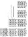
도 13 및 도 14는 LTE에서 CSI-RS가 전송될 수 있는 모든 자원 요소의 위치를 2개의 연속하는 자원블록 상에 표시한 것이다. 즉, 도 13 및 도 14는 표 1(노멀 CP), 표 2(확장 CP)에 나타낸 CSI-RS 설정 넘버에 대응하는 모든 자원 요소를 2개의 연속하는 자원블록 상에 표시한 것이다.13 and 14 show locations of all resource elements to which the CSI-RS can be transmitted in LTE on two consecutive resource blocks. That is, FIGS. 13 and 14 show all the resource elements corresponding to the CSI-RS setting numbers shown in Table 1 (normal CP) and Table 2 (extended CP) on two consecutive resource blocks.
도 13 (a) 및 도 14 (a)를 참조하면, 2개의 안테나 포트를 사용하는 경우, 0과 1로 표시된 2개의 연속하는 자원 요소를 안테나 포트 15가 사용하여 CSI-RS를 전송하고, 동일한 자원 요소들을 OCC(orthogonal code cover)하여 안테나 포트 16이 CSI-RS를 전송한다. 즉, 표 1 및 표 2에서 2개의 안테나 포트를 사용하는 경우 CSI-RS가 맵핑될 수 있는 모든 자원 요소를 표시하면 도 13(노멀 CP인 경우), 도 14(확장 CP인 경우)과 같이 표현될 수 있다. 그러면, 노멀 CP의 경우 총 20개의 CSI-RS 설정이 존재하고, 확장 CP의 경우 총 16개의 CSI-RS 설정이 존재한다.13A and 14A, when two antenna ports are used, the
만약, 4개의 안테나 포트를 사용하여 CSI-RS를 전송한다면, 2개씩의 안테나 포트가 동일한 자원 요소에 맵핑되나 OCC를 통해 구분된다. 예를 들어, 안테나 포트 15, 16이 동일한 자원요소(0, 1로 표시된 자원요소)에 맵핑되나 OCC를 통해 구분되고, 안테나 포트 17, 18이 동일한 자원요소(2, 3으로 표시된 자원요소)에 맵핑되나 OCC를 통해 구분된다. 도 13 (b), 도 14 (b)를 참조하면, 0, 1로 표시된 자원 요소에서 안테나 포트 15, 16의 CSI-RS가 맵핑되고, 2, 3으로 표시된 자원 요소에서 안테나 포트 17, 18의 CSI-RS가 맵핑된다. 그러면, 노멀 CP에서 10개의 CSI-RS 설정이 존재하고, 확장 CP에서 8개의 CSI-RS 설정이 존재한다.If four antenna ports are used to transmit CSI-RS, then two antenna ports are mapped to the same resource element but separated by OCC. For example, if
도 13 (c), 도 14 (c)를 참조하면, 안테나 포트 15, 16이 동일한 자원요소(0, 1로 표시된 자원요소)에서 CSI-RS를 전송하나 OCC를 통해 구분되고, 안테나 포트 17, 18이 동일한 자원요소(2, 3으로 표시된 자원요소)에서 CSI-RS를 전송하나 OCC를 통해 구분된다. 안테나 포트 19, 20에 대한 CSI-RS가 4, 5로 표시된 자원요소에 맵핑되고, 안테나 포트 21, 22에 대한 CSI-RS가 6, 7로 표시된 자원 요소에 맵핑된다. 그러면, 노멀 CP의 경우 총 5개의 CSI-RS 설정이 존재하고, 확장 CP의 경우 총 4개의 CSI-RS 설정이 존재한다. 상술한 바와 같이 CSI-RS 설정 넘버에 따라 안테나 포트의 개수에 따른 CSI-RS가 전송되는 자원 요소가 결정될 수 있다.13 (c) and 14 (c), the
또한, CSI-RS가 전송되는 서브프레임과 관련하여 상기 표 3을 참조하여 설명한 바와 같이, CSI-RS는 최소 5 서브프레임에서 최대 80 서브프레임 주기로 전송될 수 있다. 즉, 가상 셀 특정적 신호가 CSI-RS인 경우, CSI-RS 서브프레임 설정 넘버에 따라 가상 셀이 사용하는 CSI-RS의 전송 시점이 결정된다.
In addition, as described with reference to Table 3 with respect to the subframe in which the CSI-RS is transmitted, the CSI-RS can be transmitted in a minimum of 5 subframes and a maximum of 80 subframe periods. That is, when the virtual cell specific signal is CSI-RS, the transmission time point of the CSI-RS used by the virtual cell is determined according to the CSI-RS subframe setting number.
가상 셀 시스템에서는 개선된 단말을 지원하기 위해서 머더 셀 특정적인 CSI-RS 및 가상 셀 특정적인 CSI-RS가 전송될 수 있다.In a virtual cell system, a cell-specific CSI-RS and a virtual cell-specific CSI-RS can be transmitted to support an enhanced UE.
머더 셀 특정적인 CSI-RS는 머더 셀의 셀 ID로 생성된 참조 신호 시퀀스를 사용하여 전송되고, 개선된 단말은 동기화 신호로부터 획득한 머더 셀의 셀 ID와 머더 셀 기반의 상위 계층 메시지로부터 수신된 머더 셀의 CSI-RS 설정 넘버과 머더 셀의 CSI-RS 서브프레임 설정 넘버를 이용하여 머더 셀의 CSI-RS를 수신할 수 있다.The MS-specific CSI-RS is transmitted using the reference signal sequence generated by the cell ID of the cell, and the improved UE transmits the cell ID of the cell, which is obtained from the synchronization signal, The CSI-RS of the mother cell can be received using the CSI-RS setting number of the mother cell and the CSI-RS subframe setting number of the mother cell.
단말은 머더 셀의 CSI-RS 설정 넘버와 머더 셀의 CSI-RS 서브프레임 설정 넘버를 이용하여 가상 셀의 CSI-RS 설정과 가상 셀의 CSI-RS 서브프레임 설정을 검출할 수 있다. 왜냐하면, 본 발명에 따르면 가상 셀의 CSI-RS 설정 및 CSI-RS 서브프레임 설정은 머더 셀의 CSI-RS 설정과 CSI-RS 서브프레임 설정에 종속적이기 때문이다.The UE can detect the CSI-RS setting of the virtual cell and the CSI-RS subframe setting of the virtual cell using the CSI-RS setting number of the mother cell and the CSI-RS subframe setting number of the mother cell. This is because the CSI-RS setting and the CSI-RS subframe setting of the virtual cell are dependent on the CSI-RS setting and the CSI-RS subframe setting of the mother cell according to the present invention.
가상 셀의 CSI-RS 설정 및 CSI-RS 서브프레임 설정과 머더 셀의 CSI-RS 설정및 CSI-RS 서브프레임 설정과의 관계는 후술할 다양한 방법 중 어느 하나가 이용될 수 있다.The relationship between the CSI-RS setting of the virtual cell and the CSI-RS subframe setting, the CSI-RS setting of the mother cell, and the CSI-RS subframe setting may be any of various methods described below.
먼저, 설명의 편의를 위해 몇 가지 용어를 정의하도록 한다.First, some terms are defined for convenience of explanation.
CMCELL은 머더 셀의 CSI-RS 설정 넘버(CSI-RS configuration number)를 나타낸다. IMCELL은 머더 셀의 CSI-RS 서브프레임 설정 넘버(CSI-RS subframe configuration number)를 나타낸다. CVCELL은 가상 셀의 CSI-RS 설정 넘버를 나타낸다. IVCELL은 가상 셀의 CSI-RS 서브프레임 설정 넘버를 나타낸다.CMCELL represents the CSI-RS configuration number (CSI-RS configuration number) of the mother cell. IMCELL represents the CSI-RS subframe configuration number of the mother cell. CVCELL indicates the CSI-RS setting number of the virtual cell. IVCELL represents the CSI-RS subframe setting number of the virtual cell.
또한, 가상 셀에서 가능한 최대 CSI-RS 설정의 수를 NCC라 정의한다. 즉, NCC는 주어진 상황(예를 들어, 주어진 CSI-RS 포트의 개수, 노멀 CP인지 확장 CP인지, 프레임 구조 타입 등)에 따라 규정되는 CSI-RS 설정의 총 개수 또는 서브프레임 내에서 영-전력 CSI-RS의 설정으로 규정된 총 자원 요소 영역(nulled REs)을 이용하여 가상 셀이 전송 가능한 최대 CSI-RS 설정의 수이다.Also, the maximum number of CSI-RS settings possible in the virtual cell is defined as NCC . That is, NCC is the total number of CSI-RS settings defined in a given context (e.g., the number of given CSI-RS ports, normal CP or extended CP, frame structure type, etc.) RS is the maximum number of CSI-RS settings that can be transmitted by the virtual cell using the total resource element area (nulled REs) defined by the setting of the power CSI-RS.
Q(a, n)은 a를 n으로 나눈 몫, R(a,n)은 a를 n으로 나눈 나머지를 출력하는 연산자를 나타낸다.Q (a, n) represents a quotient of a divided by n, and R (a, n) represents an operator that outputs a remainder obtained by dividing a by n.
또한, 후술하는 방법에서 머더 셀 및 가상 셀의 CSI-RS를 전송하는 안테나 포트의 수는 동일하거나, 2 이하인 것으로 가정한다.In the method described below, it is assumed that the number of antenna ports for transmitting the CSI-RS of the mother cell and the virtual cell is equal to or less than 2.
상술한 정의를 이용하여 이하에서 가상 셀의 CSI-RS 설정 및 CSI-RS 서브프레임 설정과 머더 셀의 CSI-RS 설정및 CSI-RS 서브프레임 설정과의 관계를 설정하는 방법들을 설명한다. vmax 개의 가상 셀들 중에서, vID 번째 가상 셀은 다음과 같은 CSI-RS 설정 넘버와 CSI-RS 서브프레임 설정 넘버를 가질 수 있다. 여기서, vID는 {1, 2, ..., vmax } 중 어느 하나이다.Hereinafter, methods of setting the CSI-RS setting of the virtual cell, the CSI-RS subframe setting, the CSI-RS setting of the mother cell, and the CSI-RS subframe setting will be described below using the above definition. Among vmax virtual cells, the vID virtual cell may have the following CSI-RS setting number and CSI-RS subframe setting number. Here, vID is any one of {1, 2, ...,vmax }.
방법 1. 가상 셀들이 고정된 CSI-RS 서브프레임 설정 넘버를 가지면서, 연속적으로 CSI-RS 설정 넘버를 쉬프트하는 방법.
vID 번째 가상 셀의 CSI-RS 설정 넘버(CVCELL)과 CSI-RS 서브프레임 설정 넘버(IVCELL)는 다음 식과 같이 설정될 수 있다.vID The CSI-RS setting number (CVCELL)And the CSI-RS subframe setting number (IVCELL) Can be set as shown in the following equation.
[식 8][Equation 8]

상기 식 8에서 Δc는 CSI-RS 설정 넘버의 단계 크기(step size)를 나타내는 임의의 정수이다. 단계 크기는 CSI-RS 설정 넘버의 변화량의 단위가 되는 값일 수 있다. Δc는 예를 들어, 1일 수 있다. Ioffset은 CSI-RS 서브프레임 설정 넘버 오프셋이며, 상위 계층 신호로 시그널링되거나 미리 정해진 값일 수 있다. Ioffset은 예를 들어, 0일 수 있다.In Equation (8),?C is an arbitrary integer representing the step size of the CSI-RS setting number. The step size may be a value that is a unit of change in the CSI-RS setting number. [Delta]c may be, for example, 1. Ioffset is the CSI-RS subframe setup number offset, which may be signaled to an upper layer signal or may be a predetermined value. Ioffset may be zero, for example.
즉, 방법 1은 모든 가상 셀에서 CSI-RS 서브프레임 설정 넘버는 머더 셀 기준으로 특정 오프셋만큼 차이가 나는 고정된 값을 사용하고, CSI-RS 설정 넘버는 머더 셀로부터 Δc×vID만큼 차이가 나는 설정을 순차적으로 사용한다. 즉, 가상 셀의 CSI-RS 설정 넘버는 머더 셀(예컨대, 기지국)의 CSI-RS 설정 넘버를 가상 셀(예컨대, 가상 셀 시스템 내의 노드)의 인덱스를 기반으로 증가시킨 값일 수 있다.That is, in the
만일, Δc 와 Ncc가 서로 소이고, Ioffset이 0이라면, 머더 셀과 가상 셀은 동일한 CSI-RS 서브프레임 설정을 사용한다. 따라서, 이 방법에 의해 지원 가능한 최대 가상 셀의 수(vmax)는 (Ncc - 1)로 제한된다. 만일 Ioffset이 0이 아니라면, 이 방법으로 지원 가능한 최대 가상 셀의 수(vmax)는 Ncc로 제한된다.If Δc and Ncc are small and Ioffset is zero, then the mother cell and the virtual cell use the same CSI-RS subframe setup. Therefore, the maximum number of virtual cells (vmax ) that can be supported by this method is limited to (Ncc - 1). If Ioffset is not zero, then the maximum number of virtual cells that can be supported in this way (vmax ) is limited to Ncc .
방법 1에서 머더 셀과 가상 셀의 CSI-RS 주기가 다른 경우, 상기 CSI-RS 주기의 차이에 따라 Ioffset 값이 결정될 수 있다. 예를 들어, 가상 셀의 CSI-RS 주기가 10으로 고정되는 경우, 머더 셀의 CSI-RS 설정 넘버의 범위에 따라 Ioffset을 다음 식과 같이 정의할 수 있다.In the
[식 9][Equation 9]

상기 식 9에서, Ioffset2는 -10 < Ioffset2 < 10의 범위 안에 존재하는 정수이다. 상기 식 9를 적용하면, 가상 셀의 CSI-RS 설정 넘버가 (5 + Ioffset2)에서 (15 + Ioffset2) 사이로 제한된다.In Equation (9),Ioffset2 is an integer in the range of -10 <Ioffset2 <10. Applying Equation (9), the CSI-RS setting number of the virtual cell is limited from (5 +Ioffset2 ) to (15 +Ioffset2 ).
또는, 가상 셀의 CSI-RS 주기(TVCELL)에 따라 미리 정해진 범위 내에서 강제적으로 할당할 수도 있다.Alternatively, it may be forcibly allocated within a predetermined range according to the CSI-RS period (VCELL ) of the virtual cell.
[식 10][Equation 10]

상기 식 10에서 SMCELL은 머더 셀의 CSI-RS 서브프레임 오프셋(ΔCSI-RS)이다. 상기 식 10에서 머더 셀과 가상 셀의 CSI-RS 서브프레임 오프셋의 차이를 Ioffset 만큼 고정적으로 할당할 수 있다.WhereMCELL is the CSI-RS subframe offset (CSI-RS ) of the mother cell. In Equation (10), the difference between the CSI-RS subframe offset of the mother cell and the virtual cell can be fixedly fixed by Ioffset .
도 15는 방법 1을 예시한 도면이다.FIG. 15 is a
이하에서 방법 1 내지 방법 5에 대한 도면들은 모두 머더 셀의 CSI-RS 설정 넘버가 0이고, CSI-RS 서브프레임 설정 넘버 역시 0(즉, CSI-RS 주기가 5 서브프레임)을 가정한다. 또한, 머더 셀과 가상 셀의 CSI-RS를 전송하는 안테나 포트 개수가 2개 이하이고, 노멀 CP를 사용하는 경우를 가정한다. 또한, 모든 예에서, 단계 사이즈(step size)는 1 즉, ΔC = ΔS = 1로 가정한다. 설정 오프셋 값들(즉, Coffset = Ioffset = 0)의 값들도 0으로 가정한다. 그러나, 이러한 가정은 제한이 아니며 예시에 불과하다.Hereinafter, the methods for the
도 15를 참조하면, 가상 셀들의 총 수는 15개이다. 총 15개의 가상 셀들은 도 15에 도시한 바와 같이 동일 서브프레임 내에서 서로 다른 자원 요소들을 이용하여 CSI-RS를 전송한다. 가상 셀들의 CSI-RS 설정 넘버가 순차적으로 쉬프트되어 사용되기 때문이다.
Referring to FIG. 15, the total number of virtual cells is 15. A total of 15 virtual cells transmit CSI-RS using different resource elements in the same subframe as shown in FIG. Since the CSI-RS setting numbers of the virtual cells are sequentially shifted and used.
방법 2 : 가상 셀들의 CSI-RS 서브프레임 오프셋을 쉬프트하면서 가상 셀들의 CSI-RS 설정 넘버를 연속적으로 쉬프트하는 방법.Method 2: A method for continuously shifting the CSI-RS setting number of virtual cells while shifting the CSI-RS subframe offset of virtual cells.
vID 번째 가상 셀의 CSI-RS 설정 넘버(CVCELL)과 가상 셀의 CSI-RS 서브프레임 설정 넘버(IVCELL)은 다음 식과 같이 결정될 수 있다.vID CSI-RS set number (CVCELL) and a CSI-RS subframe set number of the virtual cells(VCELL I) in the second virtual cell can be determined by the following equation.
[식 11][Equation 11]

상기 식 11에서 Δc는 CSI-RS 설정 넘버의 단계 크기(step size)를 나타내는 정수이다. Δs는 CSI-RS 서브프레임 설정 넘버의 단계 크기를 나타내는 정수이다. TVCELL은 가상 셀의 CSI-RS 주기(TCSI-RS)이다. SMCELL은 머더 셀의 CSI-RS 서브프레임 오프셋(ΔCSI-RS)이다(SMCELL = IMCELL - TMCELL + 5).In Equation (11),?C is an integer representing the step size of the CSI-RS setting number. ?S is an integer representing the step size of the CSI-RS subframe setup number. TVCELL is the CSI-RS period (TCSI-RS ) of the virtual cell. SMCELL is the CSI-RS subframe offset (ΔCSI-RS ) of the mother cell (SMCELL = IMCELL - TMCELL + 5).
즉, 방법 2는 방법 1에서 지원할 수 있는 가상 셀의 수가 제한된다는 단점을 극복하기 위해 방법 1처럼 CSI-RS 설정 넘버를 순차적으로 쉬프트하면서 가상 셀에게 할당한 후, Δc× vID가 Ncc를 초과하는 경우 CSI-RS 서브프레임 설정 넘버를 바꿔주는 방법이다. 따라서, 방법 2를 이용하면, 최대 (TMCELL×Ncc - 1)개의 가상 셀 특정적인 CSI-RS를 전송할 수 있다. 즉, 최대 (TMCELL× Ncc - 1)개의 가상 셀에서 CSI-RS를 전송할 수 있다.In order to overcome the disadvantage that the number of virtual cells that can be supported by the
도 16은 방법 2를 예시한 도면이다.16 is a
도 16을 참조하면, 가상 셀들의 총 수는 22개이다. 이러한 총 22개의 가상 셀들에 방법 2를 적용하는 경우, 서브프레임 1에서 총 19개의 가상 셀들에 대한 CSI-RS를 전송하고, 서브프레임 1에 연속하는 서브프레임 2에서 총 3개의 가상 셀들에 대한 CSI-RS를 전송한다. 즉, 하나의 서브프레임에서 자원 요소가 겹치지 않고 전송 가능한 CSI-RS의 개수(Ncc)보다 더 많은 가상 셀이 존재하는 경우 상기 하나의 서브프레임에서 일부 가상 셀의 CSI-RS를 전송하고, 나머지 가상 셀의 CSI-RS는 연속하는 다음 서브프레임에서 전송한다.Referring to FIG. 16, the total number of virtual cells is 22. When the
방법 3. 가상 셀들이 고정된 CSI-RS 설정 넘버를 가지고, CSI-RS 서브프레임 오프셋을 연속적으로 쉬프트하는 방법.
vID 번째 가상 셀의 CSI-RS 설정 넘버(CVCELL)과 가상 셀의 CSI-RS 서브프레임 설정 넘버(IVCELL)은 다음 식과 같이 결정될 수 있다.vID CSI-RS set number (CVCELL) and a CSI-RS subframe set number of the virtual cells(VCELL I) in the second virtual cell can be determined by the following equation.
[식 12][Equation 12]

상기 식 12에서, Coffset은 CSI-RS 설정 넘버 오프셋이며, 상위 계층 신호를 통해 시그널링되거나 미리 정해진 값 예컨대 0일 수 있다. Δs는 CSI-RS 서브프레임 설정 넘버의 단계 크기를 나타내는 임의의 정수이다. TMCELL은 머더 셀의 CSI-RS 주기이다(TCSI-RS).In
즉, 방법 3은 모든 가상 셀에서 CSI-RS 설정 넘버를 머더 셀을 기준으로 특정 오프셋만큼 차이가 나도록 모두 동일하게 사용하면서(또는 머더 셀과 동일한 CSI-RS 설정 넘버를 사용하면서), CSI-RS 서브프레임 설정 넘버를 머더 셀과 Δs×vID만큼 차이가 나는 값을 순차적으로 사용하는 방법이다. 다시 말해, 가상 셀을 구성하는 노드의 CSI-RS 설정 넘버는 머더 셀을 구성하는 기지국의 CSI-RS 설정 넘버와 동일한 값(또는 고정된 값)이고, 상기 노드의 CSI-RS서브프레임 설정 넘버는 기지국의 CSI-RS 서브프레임 설정 넘버를 상기 노드의 인덱스를 기반으로 증가시킨 값일 수 있다.That is,
이 때, 가상 셀에서 전송하는 CSI-RS 주기는 머더 셀과 동일할 수 있다. 따라서, Coffset = 0인 경우 이 방법으로 CSI-RS를 전송할 수 있는 최대 가상 셀의 수는 (머더 셀의 CSI-RS 주기(TMCELL) - 1)로 제한되고, Coffset이 0이 아닌 경우에는 머더 셀의 CSI-RS 주기(TMCELL)로 제한된다.At this time, the CSI-RS period transmitted from the virtual cell may be the same as the mother cell. Thus, if the Coffset = 0, the maximum number of virtual cell that can transmit CSI-RS to the method (CSI-RS period (TMCELL) of the mother cell-1) is limited to, Coffset is not 0 Is limited to the CSI-RS period (TMCELL ) of the mother cell.
도 17은 방법 3을 예시한 도면이다.17 is a
도 17을 참조하면, 가상 셀들의 총 수가 4개인 경우 방법 3을 적용한 예를 나타낸다. 각 가상 셀들의 CSI-RS 주기는 머더 셀과 동일하게 5 서브프레임이나, CSI-RS 서브프레임 오프셋 값을 다르게 함으로써 서로 다른 서브프레임의 동일한 자원 요소에서 CSI-RS를 전송한다. 즉, 머더 셀은 서브프레임 1, 6에서 CSI-RS를 전송하고, 가상 셀 1은 서브프레임 2, 7에서 CSI-RS를 전송한다. 가상 셀 2는 서브프레임 3,8, 가상 셀 3은 서브프레임 4,9, 가상 셀 4는 서브프레임 5,10에서 CSI-RS를 전송한다.
Referring to FIG. 17, the
방법 4. 가상 셀들이 고정된 CSI-RS 설정 넘버를 가지면서, 가상 셀의 CSI-RS 서브프레임 오프셋을 쉬프트하는 방법을 일반화.
vID 번째 가상 셀의 CSI-RS 설정 넘버(CVCELL)과 가상 셀의 CSI-RS 서브프레임 설정 넘버(IVCELL)은 다음 식과 같이 결정될 수 있다.vID CSI-RS set number (CVCELL) and a CSI-RS subframe set number of the virtual cells(VCELL I) in the second virtual cell can be determined by the following equation.
[식 13][Formula 13]
CVCELL(vID) = CMCELL+ Coffset,CVCELL (vID ) = CMCELL + Coffset ,
IVCELL(vID) = TVCELL - 5 + R(Offset(vID, IMCELL), TVCELL),IVCELL (vID ) = TVCELL - 5 + R (Offset (vID , IMCELL ), TVCELL )
상기 식 13에서, TVCELL은 가상 셀의 CSI-RS 주기이며, 상위 계층 신호로 시그널링되거나, 미리 정해진 값을 결정될 수 있다. 예를 들어, TVCELL은 N × TMCELL, TVCELL = 5M으로 결정될 수 있다. 여기서, N, M은 양의 정수이다. Offset(vID, IMCELL)은 주어진 IMCELL값에 대해 vID번째 가상 셀의 CSI-RS 서브프레임 오프셋을 출력한다. 이 때, 서로 다른 vID는 서로 다른 출력 값을 가진다. 예를 들어, Offset(vID, IMCELL) = Δs × vID + SMCELL또는 Offset(vID, IMCELL) = Δs × vID과 같이 결정될 수 있다.In
방법 4는 방법 3을 좀 더 일반화한 방법으로 볼 수 있다. 즉, 모든 가상 셀은 동일한 CSI-RS 설정 넘버와 CSI-RS 주기를 갖는다. 이 때, 가상 셀의 CSI-RS 주기는 방법 3에서와 마찬가지로 머더 셀의 주기에 종속적(예컨대, TVCELL = 2 × TMCELL)일 수도 있고, 또는 비종속적일 수도 있다(예컨대, TVCELL은 상위 계층 신호로 시그널링될 수도 있다). 각 가상 셀들은 정해진 순서로 서로 다른 CSI-RS 서브프레임 설정 넘버를 부여 받는다. 가상 셀들이 서로 다른 CSI-RS 서브프레임 설정 넘버를 부여 받는다는 것은 각 가상 셀들이 동일한 CSI-RS 전송 주기를 가지되, 서로 다른 CSI-RS 서브프레임 오프셋을 가진다는 것을 의미한다.
이 경우, 머더 셀과의 간섭을 피하기 위해 머더 셀이 CSI-RS를 전송하는 서브프레임에서는 가상 셀들이 CSI-RS를 전송하지 못하도록 할 수 있다. 이러한 기법을 가상 셀 서브프레임 뮤팅(muting)이라 칭한다. 가상 셀 서브프레임 뮤팅을 위해 상술한 식 13에서In this case, it is possible to prevent the virtual cells from transmitting the CSI-RS in the subframe in which the mother cell transmits the CSI-RS in order to avoid interference with the mother cell. This technique is referred to as virtual cell subframe muting. For the virtual cell sub-frame muting,
1. Offset(vID, IMCELL) = vID + SMCELL+ Q(vID, TMCELL) 또는1. Offset (vID , IMCELL ) = vID + SMCELL + Q (vID , TMCELL ) or
2. Offset(vID, IMCELL) = vID- 1 + Q(vID- 1 + TMCELL- SMCELL, TMCELL)과 같이 규정할 수 있다. 상기 1.은 머더 셀의 CSI-RS 서브프레임 오프셋을 기준으로 하나씩 CSI-RS 서브프레임 오프셋을 늘려가면서 각 가상 셀이 CSI-RS를 전송하는 방법이다. 상기 2.은 각 가상 셀들이 CSI-RS 서브프레임 오프셋 = 0 부터 시작하여 CSI-RS 오프셋 값을 하나씩 늘려가며 CSI-RS를 전송하는 방법이다. 상술한 2가지 방법 모두 머더 셀이 CSI-RS를 전송하는 서브프레임에서는 가상 셀이 CSI-RS를 전송하지 않는다.2. Offset (vID , IMCELL ) = vID - 1 + Q (vID - 1 + TMCELL - SMCELL , TMCELL ) 1 is a method in which each virtual cell transmits a CSI-RS while increasing a CSI-RS subframe offset by one based on a CSI-RS subframe offset of a mother cell. The above 2. method is a method in which each virtual cell starts CSI-RS subframe offset = 0 and increases the CSI-RS offset value one by one to transmit the CSI-RS. In both of the above-described methods, the virtual cell does not transmit the CSI-RS in the subframe in which the mother cell transmits the CSI-RS.
이처럼 가상 셀 서브프레임 뮤팅 기법을 사용하는 경우, 가상 셀 특정적인 CSI-RS를 전송할 수 있는 가상 셀의 수는 가상 셀의 CSI-RS 주기에서 max(1, TVCELL/TMCELL)를 뺀 값으로 제한된다. 즉, vmax = TVCELL - max(1, TVCELL/TMCELL)이 된다. 만약, 가상 셀 서브프레임 뮤팅 기법이 적용되지 않는 경우에는 가상 셀 특정적인 CSI-RS를 전송할 수 있는 가상 셀의 수가 가상 셀의 CSI-RS 주기로 제한된다. 즉, vmax = TVCELL이 된다.When the virtual cell subframe muting scheme is used, the number of virtual cells capable of transmitting a virtual cell-specific CSI-RS is a value obtained by subtracting max (1, TVCELL / TMCELL ) from the CSI-RS period of the virtual cell Is limited. That is, vmax = TVCELL - max (1, TVCELL / TMCELL ). If the virtual cell subframe muting scheme is not applied, the number of virtual cells capable of transmitting virtual cell-specific CSI-RSs is limited to the CSI-RS period of the virtual cell. That is, vmax = TVCELL .
도 18은 방법 4를 예시한 도면이다.18 is a
도 18을 참조하면, 가상 셀들의 총 수가 5개인 경우 방법 4를 적용한 예를 나타낸다. 가상 셀들의 CSI-RS 주기(TVCELL = 10)는 머더 셀의 2배인 10 서브프레임이다. 이는 가상 셀들의 수가 5개이므로 전송 주기를 머더 셀 CSI-RS 주기의 배수로 설정한 경우를 나타낸다. 서브프레임 1에서 머더 셀의 CSI-RS가 전송되고, 서브프레임 2의 동일 자원 요소에서 가상 셀 1의 CSI-RS가 전송된다. 또한, 서브프레임 3에서는 가상 셀 2의 CSI-RS, 서브프레임 4에서는 가상 셀 3의 CSI-RS, 서브프레임 4에서는 가상 셀 4의 CSI-RS가 전송된다. 서브프레임 6에서는 CSI-RS 주기가 5서브프레임인 머더 셀의 CSI-RS가 전송되고, 서브프레임 7에서는 가상 셀 5의 CSI-RS가 전송된다. 즉, 도 18은 가상 셀 서브프레임 뮤팅을 적용한 것이다.
Referring to FIG. 18, the
방법 5 : 가상 셀들의 CSI-RS 서브프레임 설정 넘버를 쉬프트하고, CSI-RS 설정 넘버를 머더 셀과 동일하게 사용하되 가상 셀들이 사용할 수 있는 서브프레임이 소진되면 CSI-RS 설정 넘버를 변경하는 방법.Method 5: Change the CSI-RS setting number when the CSI-RS subframe setting number of virtual cells is shifted and the CSI-RS setting number is the same as that of the mother cell but the available subframe for virtual cells is exhausted .
vID 번째 가상 셀의 CSI-RS 설정 넘버(CVCELL)과 가상 셀의 CSI-RS 서브프레임 설정 넘버(IVCELL)은 다음 식과 같이 결정될 수 있다.vID CSI-RS set number (CVCELL) and a CSI-RS subframe set number of the virtual cells(VCELL I) in the second virtual cell can be determined by the following equation.
[식 14][Equation 14]

방법 5는 상술한 방법 3 및 방법 4에서 CSI-RS를 전송할 수 있는 가상 셀의 수가 제한된다는 단점을 극복하기 위해, 각 가상 셀들이 머더 셀과 동일한 CSI-RS 설정 넘버를 사용하되, CSI-RS 서브프레임 설정 넘버를 변화시키면서 사용하다가 가상 셀이 사용할 수 있는 서브프레임이 모두 소진되면, CSI-RS 설정 넘버를 변화시킨 후 다음 가상 셀부터 다시 CSI-RS 서브프레임 설정 넘버를 순차적으로 할당한다. 따라서, 전송 가능한 가상 셀 CSI-RS의 수가 최대 (TVCELL - max(1, TVCELL/TMCELL)) × NCC 만큼 증가한다. 즉, 가상 셀 특정적인 CSI-RS를 전송할 수 있는 가상 셀의 수가 최대 (TVCELL - max(1, TVCELL/TMCELL)) × NCC가 된다.In order to overcome the disadvantage that the number of virtual cells that can transmit the CSI-RS is limited in the
식 14에서 TVCELL - max(1, TVCELL/TMCELL)을 사용하는 것은 가상 셀 서브프레임 뮤팅을 사용하는 것을 가정했기 때문이다. 만약, 가상 셀의 CSI-RS 설정 넘버가 머더 셀과 동일한 경우에만, 가상 셀 서브프레임 뮤팅을 적용하는 것으로 한정 짓는다면 vID 번째 가상 셀의 CSI-RS 설정 넘버(CVCELL)과 가상 셀의 CSI-RS 서브프레임 설정 넘버(IVCELL)은 다음 식과 같이 결정될 수 있다.The use of TVCELL -max (1, TVCELL / TMCELL ) in
[식 15][Formula 15]

식 15에 의하면 가상 셀 CSI-RS의 수는 식 14에 비해 증가된다.According to
도 19는 방법 5를 예시한 도면이다.19 is a
도 19를 참조하면, 가상 셀들의 총 수는 15개이고, 가상 셀들의 CSI-RS 주기(TVCELL)는 5 서브프레임이다. 이러한 경우, 방법 5를 적용하면, 서브프레임 1에서는 머더 셀과 가상 셀 5, 10, 15가 CSI-RS를 서로 다른 자원 요소에서 전송한다. 서브프레임 2에서는 가상 셀 1, 6, 11이 CSI-RS를 전송하고, 서브프레임 3에서는 가상 셀 2, 7, 12가 CSI-RS를 전송하고, 서브프레임 4에서는 가상 셀 3, 8, 13이 CSI-RS를 전송하고, 서브프레임 5에서는 가상 셀 4, 9, 14가 CSI-RS를 전송한다. 이러한 시간적 패턴으로 서브프레임 6에서는 다시 머더 셀과 가상 셀 5, 10, 15가 CSI-RS를 전송하며 마찬가지로 서브프레임 7에서는 가상 셀 1, 6, 11이 CSI-RS를 전송한다. 즉, 가상 셀들이 머더 셀과 동일한 CSI-RS 설정 넘버를 사용하고, CSI-RS 서브프레임 설정 넘버를 변경하면서 CSI-RS를 전송한다. 즉, 가상 셀 1(#1) 내지 가상 셀 4(#4)는 동일한 CSI-RS 설정 넘버를 가지고, CSI-RS 서브프레임 설정 넘버를 변경하면서 CSI-RS를 전송한다. 가상 셀 5(#5)는 동일 CSI-RS 설정 넘버에서 더 이상 전송할 수 있는 서브프레임이 없으므로, CSI-RS 설정 넘버를 변경하여 서브프레임 1 내지 서브프레임 5에서 CSI-RS를 전송한다. 가상 셀 6(#6) 내지 가상 셀 9(#9)도 마찬가지이다. 가상 셀 10(#10)은 CSI-RS 설정 넘버를 변경한 후, 서브프레임 1에서 CSI-RS를 전송한다.Referring to FIG. 19, the total number of virtual cells is 15, and the CSI-RS period (VCELL ) of virtual cells is 5 subframes. In this case, when the
머더 셀과 가상 셀에서 사용하는 CSI-RS 포트의 수가 서로 다를 수 있다. 이 경우, 상술한 수식들을 변경할 필요가 있을 수 있다. 왜냐하면, 머더 셀이 사용하지만 가상 셀은 사용하지 않는 CSI-RS 안테나 포트들에 대해, 머더 셀의 CSI-RS가 사용하는 자원 요소를 가상 셀은 사용하지 않아야 하기 때문이다.The number of CSI-RS ports used in the mother cell and the virtual cell may be different. In this case, it may be necessary to change the above formulas. This is because for the CSI-RS antenna ports that are used by the mother cell but not the virtual cell, the resource element used by the CSI-RS of the mother cell must not be used by the virtual cell.
이 경우, 기본적인 자원 할당 방식에는 변함이 없으나, 가상 셀이 사용하지 말아야 할 CSI-RS 설정 넘버가 추가적으로 발생하므로 수식이 변경될 필요가 있다. 예를 들어, 노멀 CP를 사용하는 경우 머더 셀과 가상 셀이 동일 서브프레임에서 CSI-RS를 전송하는 경우, 머더 셀이 8개의 CSI-RS 안테나 포트와 CSI-RS 설정 넘버 =0을 사용하는 경우, 1 또는 2개의 CSI-RS 안테나 포트를 사용하는 가상 셀들은 CSI-RS 설정 넘버 = 0 뿐만 아니라 CSI-RS 설정 넘버 5, 10, 11도 사용하지 않아야 머더 셀이 CSI-RS를 전송하는데 사용하는 자원 요소와 겹치지 않는다. 따라서, 이러한 경우 복수의 CSI-RS 설정 넘버를 피할 수 있도록 상기 수식들이 변경될 수 있다.In this case, the basic resource allocation method does not change, but the CSI-RS setting number that the virtual cell should not use is additionally generated, so the formula needs to be changed. For example, when the normal CP is used, when the mother cell and the virtual cell transmit CSI-RS in the same subframe, when the mother cell uses eight CSI-RS antenna ports and CSI-RS setting number = 0 , Virtual cells using one or two CSI-RS antenna ports should not use CSI-
상술한 바와 같이 5가지 방법 중 어느 하나를 이용하면, 기지국이 단말에게 가상 셀의 총 개수만 알려주면, 단말은 머더 셀의 파라미터(또는 기준 파라미터)를 통해 알 수 있는 자원 요소에서 가상 셀 특정적 CSI-RS를 검출하여 각 가상 셀 특정적 CSI-RS에 대한 측정치(예를 들어, RSRP, RSRQ, 경로 손실 등)를 측정하여 기지국으로 피드백할 수 있다. 이 때, 단말은 선호하는 가상 셀에 대한 인덱스(vID)를 기지국에 피드백할 수도 있다.
As described above, if any one of the five methods is used, if the base station reports only the total number of virtual cells to the terminal, the terminal determines whether the resource element that is known through the parameter (or reference parameter) (E.g., RSRP, RSRQ, path loss, etc.) for each virtual cell-specific CSI-RS by detecting the CSI-RS. At this time, the terminal may feed back the index (vID ) of the preferred virtual cell to the base station.
<실시예 3 : 가상 셀의 안테나 포트 넘버>≪ Embodiment 3: Antenna port number of virtual cell >
이하에서는 가상 셀 파라미터가 가상 셀의 CSI-RS 안테나 포트 넘버인 경우, 어떤 방식으로 기준 파라미터로부터 획득할 수 있는지를 설명한다.Hereinafter, when the virtual cell parameter is the CSI-RS antenna port number of the virtual cell, how it can be obtained from the reference parameter will be described.
특정 기준 값 i ∈ {1, 2, ... , N}에 대하여 다음과 같은 기준 파라미터가 기지국에 의해 주어질 수 있다. 1. CSI-RS 설정 넘버 #xi, 2. CSI-RS 서브프레임 설정 넘버 #yi, 3. CSI-RS 안테나 포트의 개수 Ni.For a particular reference value i ∈ {1, 2, ..., N}, the following reference parameters can be given by the base station. 1. CSI-RS setup number #xi , 2. CSI-RS subframe setup number #yi , 3. CSI-RS antenna port number Ni .
이 경우 가상 셀 인덱스 vID(≥1 인 정수)가

[식 16][Formula 16]

이 방법은 특정 기준 파라미터에 따라 가상 셀이 사용하는 CSI-RS 안테나 포트 넘버를 하나씩 순차적으로 증가시키면서 부여하는 방법이다. 이 때, 단말은 각 CSI-RS 안테나 포트(또는 일부 CSI-RS 안테나 포트에 대한)에 대한 피드백을 기지국에게 제공할 수 있다. 이 방법에서 하나의 CSI-RS 설정 넘버 하에서 최대 CSI-RS 안테나 포트 수가 8개이므로 8개 이상의 가상 셀을 지원하기 위해서 다중 CSI-RS 설정 넘버를 가정한다.In this method, the CSI-RS antenna port number used by the virtual cell is incremented one by one according to a specific reference parameter. At this time, the terminal can provide feedback to the base station for each CSI-RS antenna port (or for some CSI-RS antenna ports). In this method, since the maximum number of CSI-RS antenna ports is eight under one CSI-RS setting number, multiple CSI-RS setting numbers are assumed to support eight or more virtual cells.
상기 기준 파라미터는 머더 셀의 파라미터와 동일하게 또는 머더 셀에 종속적으로 규정될 수 있다. 예를 들어, 기준 파라미터 중 일부 파라미터는 머더 셀과 동일하게 규정하고, 나머지 기준 파라미터의 값들은 머더 셀의 CSI-RS 설정 넘버 및/또는 CSI-RS 서브프레임 설정 넘버를 기준으로 특정 값만큼 순차적으로 차이가 나도록 규정할 수 있다.The reference parameter may be defined in the same manner as the parameter of the mother cell or dependent on the mother cell. For example, some of the reference parameters are defined the same as those of the mother cells, and the values of the remaining reference parameters are sequentially set to a specific value based on the CSI-RS setting number of the mother cell and / or the CSI- The difference can be specified.
그러면, 단말은 머더 셀의 파라미터를 획득함과 동시에 모든 기준 파라미터를 획득할 수 있으므로 기지국이 단말에게 기준 파라미터들을 명시적 시그널링으로 알려줄 필요가 없다. 따라서, 시그널링 오버헤드가 줄어드는 장점이 있다.Then, since the UE acquires the parameters of the mother cell and acquires all the reference parameters, the BS does not need to inform the UE of the reference parameters by explicit signaling. Therefore, there is an advantage that the signaling overhead is reduced.
기준 파라미터가 머더 셀의 파라미터를 따르는 경우, 머더 셀이 사용하는 CSI-RS의 전송 자원 요소는 가상 셀이 사용하지 않도록 상기 식 16을 변경할 수 있다. 예를 들어, 머더 셀이 안테나 포트 #15를 사용하는 경우, 가상 셀 #vID ∈ {1, 2, ..., Nt-1}은 머더 셀과 동일한 CSI-RS 설정 넘버와 CSI-RS 서브프레임 설정 넘버를 사용하되, 안테나 포트 #15은 제외하고 안테나 포트 #(15 + vID)를 사용하도록 수정할 수 있다.
When the reference parameter conforms to the parameters of the mother cell, the transmission resource element of the CSI-RS used by the mother cell can be changed to Equation (16) so that it is not used by the virtual cell. For example, if the mother cell uses
이하에서는 가상 셀에 기존의 셀 ID의 범위를 벗어난 셀 ID를 할당하는 방법에 대해 설명한다.Hereinafter, a method of allocating a cell ID out of the range of the existing cell ID to a virtual cell will be described.
가상 셀을 포함하는 시스템에서 레거시 단말들은 가상 셀을 이용한 기술을 구현하지 못한다. 따라서, 가상 셀들을 인지할 필요가 없다. 예를 들어, LTE 시스템의 경우, 모든 노드는 머더 셀 ID에 해당하는 동일한 CRS를 전송하고, 레거시 단말들은 이러한 CRS를 이용하여 채널을 측정하므로, 가상 셀을 인지할 수 없다.In a system including a virtual cell, legacy terminals can not implement a technology using a virtual cell. Therefore, it is not necessary to recognize virtual cells. For example, in the case of an LTE system, all nodes transmit the same CRS corresponding to a mother cell ID, and legacy terminals measure a channel using this CRS, so that a virtual cell can not be recognized.
개선된 단말을 위해서 기지국은 머더 셀 ID로 생성된 CSI-RS를 모든 가상 셀에서 동시 전송하여 가상 셀을 인지하지 못하게 할 수 있다. 또는 개선된 단말들을 위해서 각 가상 셀에서 자신의 가상 셀 ID로 생성된 RS(예컨대, CSI-RS)를 전송하여 개선된 단말로 하여금 각각의 가상 셀에 대한 채널 측정을 수행하게 할 수도 있다. 이러한 특성으로 인해 가상 셀 ID는 레거시 단말이 사용하지 않는 셀 ID를 사용할 수 있다.For the enhanced terminal, the base station can simultaneously prevent the CSI-RS generated in the cell ID from being transmitted to all the virtual cells, thereby preventing the virtual cell from being recognized. Alternatively, for improved terminals, an RS (e.g., CSI-RS) generated from its virtual cell ID in each virtual cell may be transmitted to allow the enhanced terminal to perform channel measurement for each virtual cell. Due to this characteristic, the virtual cell ID can use the cell ID that the legacy terminal does not use.
<가상 셀의 셀 ID를 할당하는 방법><Method of Assigning Cell ID of Virtual Cell>
LTE의 경우 셀 ID의 범위는 0에서 503 사이의 정수를 사용하고, IEEE 802.16에서는 0에서 767 사이의 정수를 사용한다. 이러한 기존 시스템의 셀 ID 사용 범위를 벗어나는 셀 ID를 사용하여 가상 셀 전용 동기화 신호를 기지국이 전송할 수 있다.For LTE, the range of the cell ID is an integer between 0 and 503, and in IEEE 802.16, an integer between 0 and 767 is used. The base station can transmit the virtual cell dedicated synchronization signal using the cell ID that is out of the cell ID usage range of the existing system.
즉, 기지국은 가상 셀 단말에게 가상 셀 ID를 전달하거나 가상 셀에 대한 CQI, 경로 손실 등의 측정 값을 피드백 받기 위해 각 가상 셀 별로 동기화 신호를 전송할 수 있다. 이 때, 기존 시스템의 셀 ID 사용 범위를 벗어나는 셀 ID를 사용하여 동기화 신호를 전송할 수 있다.That is, the base station may transmit a synchronization signal for each virtual cell in order to transmit a virtual cell ID to the virtual cell terminal, or to receive feedback on measurement values such as CQI and path loss for the virtual cell. At this time, the synchronization signal can be transmitted using the cell ID which is out of the cell ID use range of the existing system.
1. LTE의 경우1. In case of LTE
LTE에서는 단말은 동기화 신호를 통해 셀 ID를 획득한다. 예들 들어, NID(2)는 프라이머리 동기화 신호(PSS)를 통해, NID(1)는 세컨더리 동기화 신호(SSS)를 통해 획득한다. 즉, 단말은 PSS를 통해 NID(2)를 획득한 후에 SSS를 통해 NID(1)를 획득하여 최종적인 셀 ID를 획득한다.In LTE, a terminal acquires a cell ID through a synchronization signal. For example, NID(2) is obtained through, NID(1) is the secondary synchronization signal (SSS) with a primary synchronization signal (PSS). That is, the UE acquires NID(2) through the PSS, acquires NID(1) through the SSS, and obtains the final cell ID.
이 때, 가상 셀 ID는 임의의 0 이상의 정수 N, L에 대하여, N + 168 ≤ NID(1) ≤ N + L + 169 의 범위를 갖도록 규정할 수 있다. 그러면, 가상 셀 ID의 범위가 L에 의해 결정되므로 시그널링 오버헤드와 셀 검색 오버헤드를 조절할 수 있다.At this time, the virtual cell ID can be defined to have a range of N + 168? NID(1) ? N + L + 169 with respect to arbitrary 0 or more integers N and L. Then, since the range of the virtual cell ID is determined by L, the signaling overhead and the cell search overhead can be adjusted.
또한, 가상 셀 ID는 NID(2)를 특정 값만을 가지도록 규정할 수 있다. 특정 값은 미리 정해진 고정된 값 예를 들어, NID(2)= 0 이거나, 머더 셀 ID에 종속적인 값일 수 있다. 그러면, 단말은 가상 셀을 검색할 때, PSS 검출을 생략할 수 있는 장점이 있다. 반대로, 기지국은 가상 셀에 대한 동기화 신호를 전송할 때, SSS만 가상 셀 별로 전송할 수 있다. 단말은 가상 셀의 NID(2)값을 머더 셀 ID로부터 알 수 있거나, 또는 미리 약속된 값으로 알고 있으므로, 기지국이 단말에게 별도의 시그널링을 해 줄 필요가 없다. 따라서, 가상 셀 별로 PSS를 전송할 필요가 없다.
In addition, the virtual cell ID can define NID(2) to have only a specific value. The specific value may be a predetermined fixed value, for example NID(2) = 0, or a value dependent on the mother cell ID. Then, when the terminal searches for a virtual cell, there is an advantage that PSS detection can be omitted. On the contrary, when the base station transmits the synchronization signal for the virtual cell, only the SSS can be transmitted for each virtual cell. Terminal, or it can be seen from the mother cell ID NID(2) values of the virtual cell, or known as a preset value, there is no need to the base station by the separate signaling to the UE. Therefore, it is not necessary to transmit PSS for each virtual cell.
2. LTE & IEEE 802.16의 경우.2. For LTE & IEEE 802.16.
LTE의 PSS에서 전달하는 NID(2)는 정보량 측면에서 2비트를 가지는데 현재 0, 1, 2만 사용하며 3이라는 값은 사용하지 않고 있다. 즉, 0, 1, 2 중 어느 하나의 값만을 전달한다. 따라서, 가상 셀 ID는 NID(2)= 3을 가지도록 규정할 수 있다. IEEE 802.16의 경우, 셀 ID는 256n + Idx 으로 구할 수 있다. 이 때 가상 셀은 n =3을 사용하도록 규정할 수 있다.NID(2) are two bits in the information amount I have a side current 0, 1, 2, and uses only a value of 3 to pass in the LTE PSS is not used. In other words, only the value of 0, 1, or 2 is transmitted. Therefore, the virtual cell ID can be defined to have NID(2) = 3. In the case of IEEE 802.16, the cell ID can be obtained as 256n + Idx. At this time, the virtual cell can be defined to use n = 3.
그러면, 단말은 가상 셀 ID의 범위가 줄어들게 되므로 낮은 시그널링 오버헤드와 셀 검색 오버헤드를 얻을 수 있다. 또한, 가상 셀과 머더 셀이 전송하는 PSS 간의 간섭을 직교 시퀀스로 제어할 수 있기 때문에 가상 셀 특정적인 PSS를 전송할 수 있다. 가상 셀 특정적인 PSS는 가상 셀들의 거리가 먼 경우 단말 동기의 정확도를 높이기 위해 제공될 수 있다.Then, since the range of the virtual cell ID is reduced, the UE can obtain low signaling overhead and cell search overhead. In addition, since the interference between the virtual cell and the PSS transmitted by the mother cell can be controlled by the orthogonal sequence, the virtual cell specific PSS can be transmitted. The virtual cell specific PSS can be provided to increase the accuracy of the terminal synchronization when the distance of the virtual cells is long.
또한, 단말이 가상 셀과 비 가상 셀(이를 일반 셀이라 칭함)을 PSS만으로 쉽게 구분할 수 있다는 장점도 있다. 즉, 가상 셀이 일반 셀과 구별되는 동기화 신호를 전송하는 경우 단말은 예컨대, PSS를 획득한 후 해당 셀이 가상 셀인지 아니면 일반 셀인지를 쉽게 구분할 수 있다. 만일 가상 셀마다 동기화 신호를 전송하는 경우가 아니라도, 가상 셀마다 구분되는 참조 신호가 존재하는 경우 단말은 참조 신호를 이용하여 가상 셀인지 일반 셀인지를 구분할 수 있다.Also, there is an advantage that the terminal can easily distinguish between a virtual cell and a non-virtual cell (referred to as a general cell) only by PSS. That is, when the virtual cell transmits a synchronization signal distinguishing it from the general cell, the UE can easily distinguish whether the corresponding cell is a virtual cell or a general cell after acquiring the PSS, for example. Even if a synchronization signal is not transmitted for each virtual cell, if there is a reference signal distinguished for each virtual cell, the terminal can distinguish whether it is a virtual cell or a general cell using a reference signal.
가상 셀에 대하여 가상 셀 ID를 NID(2)= 3으로 규정하는 경우, 셀 ID를 구성하는 규칙은 변경될 수 있다. 예를 들어, NID(2)가 0 내지 2 사이의 값을 갖는 경우, NIDcell = 3NID(1) + NID(2)이지만, NID(2)가 0 내지 3 중 어느 하나의 값을 가지는 경우에는 NIDcell = 4NID(1) + NID(2)와 같이 변경될 수 있다. 이처럼 직접적인 변경 방법은 가상 셀 ID의 범위가 기존 셀 ID의 범위와 오버랩되는 범위가 발생할 수 있다. 따라서, 가상 셀 ID의 범위를 기존 셀 ID의 범위와 오버랩되지 않도록 설정할 수 있다. 예를 들면, 가상 셀 ID를 다음 식과 같은 범위로 결정할 수 있다.When the virtual cell ID is defined as NID(2) = 3 for the virtual cell, the rule configuring the cell ID can be changed. For example, NID(2) a case having a value from 0 to2, N ID cell = 3N ID (1) + N ID (2) Although, NID(2) is any one of 0 to 3, NIDcell = 4NID(1) + NID(2) in the case of having a value of " In this direct modification method, a range in which the range of the virtual cell ID overlaps with the range of the existing cell ID may occur. Therefore, the range of the virtual cell ID can be set so as not to overlap with the range of the existing cell ID. For example, the virtual cell ID can be determined in the same range as the following expression.
[식 17][Formula 17]

상기 식 17에서, 가상 셀이 504 내지 671 중 어느 하나의 값을 셀 ID로 가질 수 있다. 이 경우, 시그널링 오버헤드를 조절하기 위해 NID(2)=3인 경우에 한하여 NID(1)의 범위를 기존의 범위 즉, 0 내지 167과 다르게 설정할 수도 있다.In
식 17을 참고하여 설명한 방법은 IEEE 802. 16에도 마찬가지로 적용할 수 있다. IEEE 802. 16에서는 가상 셀 ID가 n(세그먼트 ID)이 3을 가지도록 규정한다. LTE와 달리 IEEE 802. 16에서는 셀 ID가 256n + Idx 형태로 구성되므로 셀 ID의 맵핑 방법을 새로 규정할 필요가 없다. 왜냐하면, 가상 셀 ID의 범위가 기존 셀 ID의 범위를 벗어나기 때문이다. 이 경우에도 n=3인 경우에 한하여 Idx의 범위를 기존의 범위(즉, 0 내지 255 중 어느 하나의 값)와 다르게 설정하여 시그널링 오버헤드를 줄일 수 있다.The method described with reference to
도 20은 기지국 및 단말을 나타내는 블록도이다.20 is a block diagram showing a base station and a terminal.
기지국(100)은 프로세서(processor, 110), 메모리(memory, 120) 및 RF부(RF(radio frequency) unit, 130)를 포함한다. 프로세서(110)는 제안된 기능, 과정 및/또는 방법을 구현한다. 즉, 단말에게 기준 파라미터를 전송하고, 각 노드에서 노드 특정적인 신호 즉, 가상 셀 특정적 신호를 전송하도록 제어한다. 메모리(120)는 프로세서(110)와 연결되어, 프로세서(110)를 구동하기 위한 다양한 정보를 저장한다. RF부(130)는 프로세서(110)와 연결되어, 무선 신호를 전송 및/또는 수신한다. RF부(130)는 유선으로 기지국(100)에 연결된 복수의 노드로 구성될 수 있다.The
단말(200)은 프로세서(210), 메모리(220) 및 RF부(230)를 포함한다. 프로세서(210)는 기지국으로부터 기준 파라미터를 수신하고, 복수의 노드 중 적어도 하나의 노드로부터 노드 특정적인 신호를 수신한다. 노드 특정적인 신호는 상술한 가상 셀 특정적 신호 예컨대, 가상 셀 별로 구분되는 CSI-RS 일 수 있다. 노드 특정적인 신호의 디코딩에 필요한 가상 셀 파라미터는 기준 파라미터를 기반으로 결정한다. 메모리(220)는 프로세서(210)와 연결되어, 프로세서(210)를 구동하기 위한 다양한 정보를 저장한다. RF부(230)는 프로세서(210)와 연결되어, 무선 신호를 전송 및/또는 수신한다.The terminal 200 includes a
프로세서(110,210)는 ASIC(application-specific integrated circuit), 다른 칩셋, 논리 회로, 데이터 처리 장치 및/또는 베이스밴드 신호 및 무선 신호를 상호 변환하는 변환기를 포함할 수 있다. 메모리(120,220)는 ROM(read-only memory), RAM(random access memory), 플래쉬 메모리, 메모리 카드, 저장 매체 및/또는 다른 저장 장치를 포함할 수 있다. RF부(130,230)는 무선 신호를 전송 및/또는 수신하는 하나 이상의 안테나를 포함할 수 있다. 실시예가 소프트웨어로 구현될 때, 상술한 기법은 상술한 기능을 수행하는 모듈(과정, 기능 등)로 구현될 수 있다. 모듈은 메모리(120,220)에 저장되고, 프로세서(110,210)에 의해 실행될 수 있다. 메모리(120,220)는 프로세서(110,210) 내부 또는 외부에 있을 수 있고, 잘 알려진 다양한 수단으로 프로세서(110,210)와 연결될 수 있다.The
본 발명은 하드웨어, 소프트웨어 또는 이들의 조합으로 구현될 수 있다. 하드웨어 구현에 있어, 상술한 기능을 수행하기 위해 디자인된 ASIC(application specific integrated circuit), DSP(digital signal processing), PLD(programmable logic device), FPGA(field programmable gate array), 프로세서, 제어기, 마이크로 프로세서, 다른 전자 유닛 또는 이들의 조합으로 구현될 수 있다. 소프트웨어 구현에 있어, 상술한 기능을 수행하는 모듈로 구현될 수 있다. 소프트웨어는 메모리 유닛에 저장될 수 있고, 프로세서에 의해 실행된다. 메모리 유닛이나 프로세서는 당업자에게 잘 알려진 다양한 수단을 채용할 수 있다.The present invention may be implemented in hardware, software, or a combination thereof. (DSP), a programmable logic device (PLD), a field programmable gate array (FPGA), a processor, a controller, a microprocessor, and the like, which are designed to perform the above- , Other electronic units, or a combination thereof. In software implementation, it may be implemented as a module that performs the above-described functions. The software may be stored in a memory unit and executed by a processor. The memory unit or processor may employ various means well known to those skilled in the art.
이상, 본 발명의 바람직한 실시예에 대해 상세히 기술하였지만, 본 발명이 속하는 기술분야에 있어서 통상의 지식을 가진 사람이라면, 첨부된 청구 범위에 정의된 본 발명의 정신 및 범위를 벗어나지 않으면서 본 발명을 여러 가지로 변형 또는, 변경하여 실시할 수 있음을 알 수 있을 것이다. 따라서, 본 발명의 앞으로의 실시예들의 변경은 본 발명의 기술을 벗어날 수 없을 것이다.While the present invention has been particularly shown and described with reference to exemplary embodiments thereof, it is evident that many alternatives, modifications and variations will be apparent to those skilled in the art. It will be understood that various modifications and changes may be made without departing from the spirit and scope of the invention. Accordingly, modifications of the embodiments of the present invention will not depart from the scope of the present invention.
Claims (12)
Translated fromKorean상기 기지국으로부터 기준 파라미터를 수신하고,
상기 복수의 노드 중 적어도 하나의 노드로부터 노드 특정적인 신호를 수신하고, 및
상기 노드 특정적인 신호를 디코딩하되,
상기 노드 특정적인 신호의 디코딩에 필요한 가상 셀 파라미터는 상기 기준 파라미터를 기반으로 결정되고, 상기 노드 특정적인 신호는 상기 기준 파라미터에 종속되는 가상 셀 파라미터의 후보들을 각각 이용하여 디코딩하고,
상기 노드 특정적인 신호가 채널 상태 정보 참조 신호(channel state information-reference signal: CSI-RS)인 경우, 상기 CSI-RS의 안테나 포트 넘버는 상기 기준 파라미터에 포함된 상기 기지국의 안테나 포트 넘버를 상기 적어도 하나의 노드의 인덱스를 기반으로 증가시켜 사용하는 것을 특징으로 하는 방법.A method of receiving a signal in a multi-node system including a plurality of nodes and a base station controlling the plurality of nodes,
Receiving a reference parameter from the base station,
Receive a node-specific signal from at least one of the plurality of nodes, and
Decoding the node specific signal,
Wherein a virtual cell parameter required for decoding the node specific signal is determined based on the reference parameter and the node specific signal is decoded using each of the candidates of a virtual cell parameter dependent on the reference parameter,
If the node-specific signal is a channel state information-reference signal (CSI-RS), the antenna port number of the CSI-RS is set to the antenna port number of the base station included in the reference parameter, And increasing the index based on the index of one node.
상기 RF부에 연결되는 프로세서를 포함하되,
상기 프로세서는 복수의 노드와 상기 복수의 노드를 제어하는 기지국을 포함하는 다중 노드 시스템에서의 상기 기지국으로부터 기준 파라미터를 수신하고,
상기 복수의 노드 중 적어도 하나의 노드로부터 노드 특정적인 신호를 수신하고,
상기 노드 특정적인 신호를 디코딩하되,
상기 노드 특정적인 신호의 디코딩에 필요한 가상 셀 파라미터는 상기 기준 파라미터를 기반으로 결정되고, 상기 노드 특정적인 신호는 상기 기준 파라미터에 종속되는 가상 셀 파라미터의 후보들을 각각 이용하여 디코딩하고,
상기 노드 특정적인 신호가 CSI-RS인 경우, 상기 CSI-RS의 안테나 포트 넘버는 상기 기준 파라미터에 포함된 상기 기지국의 안테나 포트 넘버를 상기 적어도 하나의 노드의 인덱스를 기반으로 증가시켜 사용하는 것을 특징으로 하는 신호 수신 장치.An RF unit for transmitting and receiving a radio signal; And
And a processor coupled to the RF unit,
The processor receiving a reference parameter from the base station in a multi-node system including a plurality of nodes and a base station controlling the plurality of nodes,
Receiving a node-specific signal from at least one of the plurality of nodes,
Decoding the node specific signal,
Wherein a virtual cell parameter required for decoding the node specific signal is determined based on the reference parameter and the node specific signal is decoded using each of the candidates of a virtual cell parameter dependent on the reference parameter,
And the antenna port number of the CSI-RS is used by increasing the antenna port number of the base station included in the reference parameter based on the index of the at least one node when the node-specific signal is CSI-RS. .
Priority Applications (5)
| Application Number | Priority Date | Filing Date | Title |
|---|---|---|---|
| EP11856220.6AEP2666245B1 (en) | 2011-01-19 | 2011-11-07 | Method and apparatus for receiving signal in multi-node system |
| PCT/KR2011/008411WO2012099322A1 (en) | 2011-01-19 | 2011-11-07 | Method and apparatus for receiving signal in multi-node system |
| US13/980,488US9179351B2 (en) | 2011-01-19 | 2011-11-07 | Method and apparatus for receiving signal in multi-node system |
| JP2013550381AJP5698384B2 (en) | 2011-01-19 | 2011-11-07 | Signal receiving method and apparatus in multi-node system |
| CN201180065516.9ACN103314536B (en) | 2011-01-19 | 2011-11-07 | The method and apparatus of Received signal strength in multi-node system |
Applications Claiming Priority (2)
| Application Number | Priority Date | Filing Date | Title |
|---|---|---|---|
| US201161434398P | 2011-01-19 | 2011-01-19 | |
| US61/434,398 | 2011-01-19 |
Publications (2)
| Publication Number | Publication Date |
|---|---|
| KR20120084243A KR20120084243A (en) | 2012-07-27 |
| KR101777424B1true KR101777424B1 (en) | 2017-09-12 |
Family
ID=46715240
Family Applications (1)
| Application Number | Title | Priority Date | Filing Date |
|---|---|---|---|
| KR1020110056675AExpired - Fee RelatedKR101777424B1 (en) | 2011-01-19 | 2011-06-13 | Method and apparatus for receiving signal in multi-node system |
Country Status (6)
| Country | Link |
|---|---|
| US (1) | US9179351B2 (en) |
| EP (1) | EP2666245B1 (en) |
| JP (1) | JP5698384B2 (en) |
| KR (1) | KR101777424B1 (en) |
| CN (1) | CN103314536B (en) |
| WO (1) | WO2012099322A1 (en) |
Families Citing this family (61)
| Publication number | Priority date | Publication date | Assignee | Title |
|---|---|---|---|---|
| US11451275B2 (en) | 2004-04-02 | 2022-09-20 | Rearden, Llc | System and method for distributed antenna wireless communications |
| US10425134B2 (en) | 2004-04-02 | 2019-09-24 | Rearden, Llc | System and methods for planned evolution and obsolescence of multiuser spectrum |
| US11309943B2 (en) | 2004-04-02 | 2022-04-19 | Rearden, Llc | System and methods for planned evolution and obsolescence of multiuser spectrum |
| US10985811B2 (en) | 2004-04-02 | 2021-04-20 | Rearden, Llc | System and method for distributed antenna wireless communications |
| US11394436B2 (en) | 2004-04-02 | 2022-07-19 | Rearden, Llc | System and method for distributed antenna wireless communications |
| US9264097B2 (en) | 2009-06-04 | 2016-02-16 | Qualcomm Incorporated | Interference mitigation for downlink in a wireless communication system |
| US20130336193A1 (en) | 2012-06-19 | 2013-12-19 | Qualcomm Incorporated | Network information for assisting user equipment |
| KR102585652B1 (en) | 2011-01-07 | 2023-10-05 | 인터디지탈 패튼 홀딩스, 인크 | Communicating channel state information (csi) of multiple transmission points |
| KR101777424B1 (en)* | 2011-01-19 | 2017-09-12 | 엘지전자 주식회사 | Method and apparatus for receiving signal in multi-node system |
| KR101856235B1 (en) | 2011-02-11 | 2018-05-10 | 한국전자통신연구원 | Wireless communication system using multiple transmission and reception point |
| US8948293B2 (en)* | 2011-04-20 | 2015-02-03 | Texas Instruments Incorporated | Downlink multiple input multiple output enhancements for single-cell with remote radio heads |
| JP5906529B2 (en)* | 2011-08-02 | 2016-04-20 | シャープ株式会社 | Base station, terminal, communication system and communication method |
| MY164105A (en)* | 2011-08-12 | 2017-11-30 | Interdigital Patent Holdings Inc | Interference measurement in wireless networks |
| WO2013035992A1 (en)* | 2011-09-06 | 2013-03-14 | 엘지전자 주식회사 | Method and apparatus for measuring interference in a wireless communication system |
| US20140241301A1 (en)* | 2011-09-28 | 2014-08-28 | Sharp Kabushiki Kaisha | Mobile station apparatus, communication system, communication method, and integrated circuit |
| US9853783B2 (en)* | 2011-09-30 | 2017-12-26 | Samsung Electronics Co., Ltd | Method and apparatus for transmitting and receiving signal in distributed antenna system |
| US9723496B2 (en)* | 2011-11-04 | 2017-08-01 | Qualcomm Incorporated | Method and apparatus for interference cancellation by a user equipment using blind detection |
| CN103166734B (en)* | 2011-12-14 | 2017-08-25 | 华为技术有限公司 | The acquisition methods and device of channel condition information |
| KR20130084149A (en)* | 2012-01-16 | 2013-07-24 | 한국전자통신연구원 | Method for transmitting preamble, synchronization method of wireless node and apparatus thereof |
| US9119209B2 (en)* | 2012-03-30 | 2015-08-25 | Samsung Electronics Co., Ltd. | Apparatus and method for channel-state-information pilot design for an advanced wireless network |
| EP2856661A2 (en) | 2012-06-04 | 2015-04-08 | Interdigital Patent Holdings, Inc. | Communicating channel state information (csi) of multiple transmission points |
| US9686772B2 (en) | 2012-08-01 | 2017-06-20 | Qualcomm Incorporated | Methods and apparatus for coordinated multipoint (CoMP) communications |
| JP6352913B2 (en)* | 2012-08-03 | 2018-07-04 | 日本テキサス・インスツルメンツ株式会社 | Uplink signaling for coordinated multipoint communications |
| JP5715601B2 (en)* | 2012-08-29 | 2015-05-07 | 株式会社Nttドコモ | Mobile communication method, radio base station, and mobile station |
| WO2014038901A1 (en)* | 2012-09-09 | 2014-03-13 | 엘지전자 주식회사 | Method and apparatus for transmitting and receiving data |
| CN104272609B (en) | 2012-09-16 | 2017-11-24 | Lg 电子株式会社 | Method and device for receiving data in a wireless communication system supporting cooperative transmission |
| ES3018481T3 (en)* | 2012-09-27 | 2025-05-16 | Electronics & Telecommunications Res Inst | Method for signaling control information for coordinated multipoint transmission in a wireless communication system |
| US10194346B2 (en) | 2012-11-26 | 2019-01-29 | Rearden, Llc | Systems and methods for exploiting inter-cell multiplexing gain in wireless cellular systems via distributed input distributed output technology |
| US11189917B2 (en) | 2014-04-16 | 2021-11-30 | Rearden, Llc | Systems and methods for distributing radioheads |
| US11190947B2 (en) | 2014-04-16 | 2021-11-30 | Rearden, Llc | Systems and methods for concurrent spectrum usage within actively used spectrum |
| US11050468B2 (en) | 2014-04-16 | 2021-06-29 | Rearden, Llc | Systems and methods for mitigating interference within actively used spectrum |
| GB2509162B (en)* | 2012-12-21 | 2018-09-26 | Sony Corp | Telecommunications apparatus and methods |
| CN109743148B (en)* | 2012-12-31 | 2021-11-19 | 上海华为技术有限公司 | Reference signal configuration method, reference signal sending method and related equipment |
| HK1214716A1 (en)* | 2013-01-02 | 2016-07-29 | Zte维创通讯公司 | Method and apparatus for a hybrid node in a cellular wireless communication system |
| US10164698B2 (en) | 2013-03-12 | 2018-12-25 | Rearden, Llc | Systems and methods for exploiting inter-cell multiplexing gain in wireless cellular systems via distributed input distributed output technology |
| RU2767777C2 (en) | 2013-03-15 | 2022-03-21 | Риарден, Ллк | Systems and methods of radio frequency calibration using the principle of reciprocity of channels in wireless communication with distributed input - distributed output |
| US9374719B2 (en)* | 2013-04-03 | 2016-06-21 | Qualcomm Incorporated | Channel state information reference signal (CSI-RS) handling for network assisted interference cancellation |
| US9426673B2 (en)* | 2013-04-05 | 2016-08-23 | Qualcomm Incorporated | Virtual cell management for interference suppression and interference cancellation in LTE |
| US20140301298A1 (en)* | 2013-04-05 | 2014-10-09 | Qualcomm Incorporated | Methods and apparatus for transmission restriction and efficient signaling |
| CN105075319B (en)* | 2013-04-09 | 2018-12-14 | 松下电器(美国)知识产权公司 | Method for mapping channel state information reference signal port to resource block, base station and user equipment |
| US9655088B2 (en)* | 2013-04-17 | 2017-05-16 | Qualcomm Incorporated | Utilizing unused uplink sequence shifts for signaling |
| EP2995035A2 (en) | 2013-05-08 | 2016-03-16 | Interdigital Patent Holdings, Inc. | Methods, systems and apparatuses for network assisted interference cancellation and/or suppression (naics) in long term evolution (lte) systems |
| WO2014193010A1 (en)* | 2013-05-31 | 2014-12-04 | 엘지전자 주식회사 | Method and apparatus for receiving control information for removing interference of adjacent cell in wireless access system |
| US20150063253A1 (en)* | 2013-09-05 | 2015-03-05 | Qualcomm Incorporated | Methods for neighbor csi-rs detection |
| US9930629B2 (en)* | 2013-11-05 | 2018-03-27 | Lg Electronics Inc. | Method and apparatus for wireless communication with dual connectivity |
| EP3751910A1 (en)* | 2013-11-21 | 2020-12-16 | Huawei Technologies Co., Ltd. | Systems and methods for non-cellular wireless access |
| KR101821071B1 (en)* | 2014-01-15 | 2018-01-22 | 엘지전자 주식회사 | Method for performing cell search procedure and user equipment for performing search procedure on basis of search signal in wireless communication system |
| US9712342B2 (en)* | 2014-04-11 | 2017-07-18 | Newracom, Inc. | Frame transmitting method and frame receiving method |
| US12177050B2 (en)* | 2014-04-11 | 2024-12-24 | Atlas Global Technologies Llc | Frame transmitting method and frame receiving method |
| KR20150118029A (en)* | 2014-04-11 | 2015-10-21 | 뉴라컴 인코포레이티드 | Frame transmitting method and frame receiving method |
| US11290162B2 (en) | 2014-04-16 | 2022-03-29 | Rearden, Llc | Systems and methods for mitigating interference within actively used spectrum |
| US9820205B2 (en)* | 2014-07-29 | 2017-11-14 | Qualcomm Incorporated | Signaling virtual cell ID sets |
| EP2988543A1 (en)* | 2014-08-20 | 2016-02-24 | DoCoMo Communications Laboratories Europe GmbH | Method and apparatus for measuring channel state information in a cellular network system using mimo |
| CN106575996B (en) | 2014-09-25 | 2019-10-15 | 英特尔Ip公司 | Transmission of generic control messages for machine type communication (MTC) user equipment over reduced bandwidth |
| US10122431B2 (en)* | 2014-10-01 | 2018-11-06 | Lg Electronics Inc. | Method for configuring reference signal for three-dimensional MIMO in wireless communication system and apparatus therefor |
| CN104967471B (en)* | 2015-05-06 | 2018-01-05 | 西安交通大学 | A kind of channel feedback method in full dimension MIMO systems |
| US10757754B2 (en) | 2016-10-27 | 2020-08-25 | Qualcomm Incorporated | Techniques for securing PDCP control PDU |
| US11140614B2 (en)* | 2017-03-15 | 2021-10-05 | Telefonaktiebolaget Lm Ericsson (Publ) | Combined layer 3 and downlink control information (DCI) signaling of virtual cell id |
| US10972169B2 (en)* | 2017-11-06 | 2021-04-06 | Lg Electronics Inc. | Method for feedback of channel quality information in wireless communication system, and device for same |
| US11310267B2 (en)* | 2019-04-29 | 2022-04-19 | Semiconductor Components Industries, Llc | Secure channel state information with adaptive obfuscation |
| CN112398554B (en)* | 2019-08-16 | 2022-06-07 | 华为技术有限公司 | Method for channel measurement and terminal device |
Family Cites Families (12)
| Publication number | Priority date | Publication date | Assignee | Title |
|---|---|---|---|---|
| US7155229B2 (en)* | 2002-01-08 | 2006-12-26 | Ericsson Inc. | Distributed wireless architecture using microcast |
| US7570615B2 (en)* | 2003-10-20 | 2009-08-04 | Telefonaktiebolaget Lm Ericsson (Publ) | Resource-sharing cells |
| JP4319633B2 (en) | 2004-02-17 | 2009-08-26 | 三星電子株式会社 | Apparatus and method for transmitting and receiving data in a multi-user multi-input multi-output system |
| KR20080077793A (en)* | 2007-02-21 | 2008-08-26 | 삼성전자주식회사 | System and method cell formation using distributed antenna in wimax mobile communication system |
| US9544776B2 (en)* | 2008-03-25 | 2017-01-10 | Qualcomm Incorporated | Transmission and reception of dedicated reference signals |
| EP2237583A1 (en)* | 2009-03-30 | 2010-10-06 | BRITISH TELECOMMUNICATIONS public limited company | Cellular mobile communications system |
| CN101909299A (en) | 2009-06-05 | 2010-12-08 | 中兴通讯股份有限公司 | Processing method of collaborated multi-input multi-output and relay station |
| KR101771257B1 (en)* | 2010-12-03 | 2017-08-25 | 엘지전자 주식회사 | Method and apparatus for cooperative transmisstion in multi node system |
| KR101777424B1 (en)* | 2011-01-19 | 2017-09-12 | 엘지전자 주식회사 | Method and apparatus for receiving signal in multi-node system |
| EP2670057A4 (en)* | 2011-01-27 | 2017-06-28 | LG Electronics Inc. | Channel status information feedback method and apparatus in multi-node system |
| CN103404046B (en)* | 2011-03-01 | 2016-09-07 | Lg电子株式会社 | Method and device for searching control information by terminal in multi-node system |
| US10057893B2 (en)* | 2012-05-10 | 2018-08-21 | Qualcomm Incorporated | Interaction of sounding reference signals with uplink channels for coordinated multi-point operations |
- 2011
- 2011-06-13KRKR1020110056675Apatent/KR101777424B1/ennot_activeExpired - Fee Related
- 2011-11-07WOPCT/KR2011/008411patent/WO2012099322A1/enactiveApplication Filing
- 2011-11-07CNCN201180065516.9Apatent/CN103314536B/ennot_activeExpired - Fee Related
- 2011-11-07USUS13/980,488patent/US9179351B2/ennot_activeExpired - Fee Related
- 2011-11-07EPEP11856220.6Apatent/EP2666245B1/ennot_activeNot-in-force
- 2011-11-07JPJP2013550381Apatent/JP5698384B2/ennot_activeExpired - Fee Related
Non-Patent Citations (3)
| Title |
|---|
| CATT, "Interference Measurement over Muted RE", 3GPP TSG RAN WG1 Meeting #63bis R1-110049(2011.01.11.)* |
| SAMSUNG, "Discussions on CSI-RS for LTE-Advanced", 3GPP TSG RAN WG1 R1-093375(2009.08.19.) |
| ZTE, "Measurement of Access downlink of Type II Relay", 3GPP TSG RAN WG1 R1-092471(2009.06.23.) |
Also Published As
| Publication number | Publication date |
|---|---|
| EP2666245A1 (en) | 2013-11-27 |
| EP2666245B1 (en) | 2018-10-17 |
| KR20120084243A (en) | 2012-07-27 |
| CN103314536B (en) | 2016-03-30 |
| CN103314536A (en) | 2013-09-18 |
| WO2012099322A1 (en) | 2012-07-26 |
| JP5698384B2 (en) | 2015-04-08 |
| EP2666245A4 (en) | 2015-04-08 |
| JP2014508445A (en) | 2014-04-03 |
| US9179351B2 (en) | 2015-11-03 |
| US20130301467A1 (en) | 2013-11-14 |
Similar Documents
| Publication | Publication Date | Title |
|---|---|---|
| KR101777424B1 (en) | Method and apparatus for receiving signal in multi-node system | |
| US10841912B2 (en) | Methods, network nodes and user equipments in a wireless network for communicating an EPDCCH | |
| US11678206B2 (en) | Terminal, base station and radio communication method using a plurality of synchronization signal blocks | |
| US9681429B2 (en) | Method and device for allocating search space of control channel in subframe | |
| EP3145109B1 (en) | Csi-rs and dmrs co-location indication | |
| US8838159B2 (en) | Method and apparatus for transmitting reference signal in multi-node system | |
| KR102036161B1 (en) | Method and apparatus for providing data service using broadcasting signal | |
| CN105191470B (en) | User terminal, wireless base station and wireless communications method | |
| KR101770571B1 (en) | Method and apparatus for transmitting sinchronization signal in multi-node system | |
| KR20130094284A (en) | Method and device whereby base station allocates nodes to terminal in a semi-static fashion in multi-node system | |
| JPWO2020035947A1 (en) | Wireless communication device and wireless communication method | |
| AU2018433296B2 (en) | User terminal | |
| WO2018025906A1 (en) | User terminal and wireless communication method | |
| US9264918B2 (en) | Resource allocation method and device in multi-node system | |
| US20150282131A1 (en) | Communication system, base station apparatus and communication method | |
| KR101833065B1 (en) | Method and apparatus for transmitting reference signal in multi-node system | |
| CN115804186A (en) | Terminal, wireless communication method, and base station | |
| CN115553004A (en) | Terminal, wireless communication method, and base station |
Legal Events
| Date | Code | Title | Description |
|---|---|---|---|
| PA0109 | Patent application | St.27 status event code:A-0-1-A10-A12-nap-PA0109 | |
| PG1501 | Laying open of application | St.27 status event code:A-1-1-Q10-Q12-nap-PG1501 | |
| R17-X000 | Change to representative recorded | St.27 status event code:A-3-3-R10-R17-oth-X000 | |
| PN2301 | Change of applicant | St.27 status event code:A-3-3-R10-R13-asn-PN2301 St.27 status event code:A-3-3-R10-R11-asn-PN2301 | |
| A201 | Request for examination | ||
| E13-X000 | Pre-grant limitation requested | St.27 status event code:A-2-3-E10-E13-lim-X000 | |
| P11-X000 | Amendment of application requested | St.27 status event code:A-2-2-P10-P11-nap-X000 | |
| P13-X000 | Application amended | St.27 status event code:A-2-2-P10-P13-nap-X000 | |
| PA0201 | Request for examination | St.27 status event code:A-1-2-D10-D11-exm-PA0201 | |
| E902 | Notification of reason for refusal | ||
| PE0902 | Notice of grounds for rejection | St.27 status event code:A-1-2-D10-D21-exm-PE0902 | |
| E13-X000 | Pre-grant limitation requested | St.27 status event code:A-2-3-E10-E13-lim-X000 | |
| P11-X000 | Amendment of application requested | St.27 status event code:A-2-2-P10-P11-nap-X000 | |
| P13-X000 | Application amended | St.27 status event code:A-2-2-P10-P13-nap-X000 | |
| E701 | Decision to grant or registration of patent right | ||
| PE0701 | Decision of registration | St.27 status event code:A-1-2-D10-D22-exm-PE0701 | |
| GRNT | Written decision to grant | ||
| PR0701 | Registration of establishment | St.27 status event code:A-2-4-F10-F11-exm-PR0701 | |
| PR1002 | Payment of registration fee | St.27 status event code:A-2-2-U10-U11-oth-PR1002 Fee payment year number:1 | |
| PG1601 | Publication of registration | St.27 status event code:A-4-4-Q10-Q13-nap-PG1601 | |
| PN2301 | Change of applicant | St.27 status event code:A-5-5-R10-R13-asn-PN2301 St.27 status event code:A-5-5-R10-R11-asn-PN2301 | |
| PC1903 | Unpaid annual fee | St.27 status event code:A-4-4-U10-U13-oth-PC1903 Not in force date:20200906 Payment event data comment text:Termination Category : DEFAULT_OF_REGISTRATION_FEE | |
| PC1903 | Unpaid annual fee | St.27 status event code:N-4-6-H10-H13-oth-PC1903 Ip right cessation event data comment text:Termination Category : DEFAULT_OF_REGISTRATION_FEE Not in force date:20200906 |