KR101776018B1 - Method for heating a substrate and Apparatus for treating a substrate - Google Patents
Method for heating a substrate and Apparatus for treating a substrateDownload PDFInfo
- Publication number
- KR101776018B1 KR101776018B1KR1020150146869AKR20150146869AKR101776018B1KR 101776018 B1KR101776018 B1KR 101776018B1KR 1020150146869 AKR1020150146869 AKR 1020150146869AKR 20150146869 AKR20150146869 AKR 20150146869AKR 101776018 B1KR101776018 B1KR 101776018B1
- Authority
- KR
- South Korea
- Prior art keywords
- substrate
- chamber
- heating
- heating plate
- upper chamber
- Prior art date
- Legal status (The legal status is an assumption and is not a legal conclusion. Google has not performed a legal analysis and makes no representation as to the accuracy of the status listed.)
- Active
Links
Images


Classifications
- H—ELECTRICITY
- H01—ELECTRIC ELEMENTS
- H01L—SEMICONDUCTOR DEVICES NOT COVERED BY CLASS H10
- H01L21/00—Processes or apparatus adapted for the manufacture or treatment of semiconductor or solid state devices or of parts thereof
- H01L21/02—Manufacture or treatment of semiconductor devices or of parts thereof
- H01L21/027—Making masks on semiconductor bodies for further photolithographic processing not provided for in group H01L21/18 or H01L21/34
- H—ELECTRICITY
- H01—ELECTRIC ELEMENTS
- H01L—SEMICONDUCTOR DEVICES NOT COVERED BY CLASS H10
- H01L21/00—Processes or apparatus adapted for the manufacture or treatment of semiconductor or solid state devices or of parts thereof
- H01L21/02—Manufacture or treatment of semiconductor devices or of parts thereof
- H01L21/04—Manufacture or treatment of semiconductor devices or of parts thereof the devices having potential barriers, e.g. a PN junction, depletion layer or carrier concentration layer
- H01L21/18—Manufacture or treatment of semiconductor devices or of parts thereof the devices having potential barriers, e.g. a PN junction, depletion layer or carrier concentration layer the devices having semiconductor bodies comprising elements of Group IV of the Periodic Table or AIIIBV compounds with or without impurities, e.g. doping materials
- H01L21/30—Treatment of semiconductor bodies using processes or apparatus not provided for in groups H01L21/20 - H01L21/26
- H01L21/324—Thermal treatment for modifying the properties of semiconductor bodies, e.g. annealing, sintering
- H—ELECTRICITY
- H01—ELECTRIC ELEMENTS
- H01L—SEMICONDUCTOR DEVICES NOT COVERED BY CLASS H10
- H01L21/00—Processes or apparatus adapted for the manufacture or treatment of semiconductor or solid state devices or of parts thereof
- H01L21/67—Apparatus specially adapted for handling semiconductor or electric solid state devices during manufacture or treatment thereof; Apparatus specially adapted for handling wafers during manufacture or treatment of semiconductor or electric solid state devices or components ; Apparatus not specifically provided for elsewhere
- H01L21/67005—Apparatus not specifically provided for elsewhere
- H01L21/67011—Apparatus for manufacture or treatment
- H01L21/67098—Apparatus for thermal treatment
Landscapes
- Engineering & Computer Science (AREA)
- Physics & Mathematics (AREA)
- Condensed Matter Physics & Semiconductors (AREA)
- General Physics & Mathematics (AREA)
- Manufacturing & Machinery (AREA)
- Computer Hardware Design (AREA)
- Microelectronics & Electronic Packaging (AREA)
- Power Engineering (AREA)
- Exposure Of Semiconductors, Excluding Electron Or Ion Beam Exposure (AREA)
Abstract
Translated fromKoreanDescription
Translated fromKorean본 발명은 기판에 가열하는 방법 및 이를 포함하는 기판 처리 장치에 관한 것이다.The present invention relates to a method of heating a substrate and a substrate processing apparatus including the same.
일반적으로 반도체 소자를 제조하기 위해서는 세정, 증착, 포토 리소그래피, 에칭, 그리고 이온주입 등과 같은 다양한 공정이 수행된다. 패턴을 형성하기 위해 수행되는 포토 리소그래피 공정은 반도체 소자의 고집적화를 이루는데 중요한 역할을 수행한다.In general, various processes such as cleaning, deposition, photolithography, etching, and ion implantation are performed to manufacture semiconductor devices. The photolithography process performed to form the pattern plays an important role in achieving the high integration of the semiconductor device.
포토리소그래피 공정은 실리콘으로 이루어진 반도체 기판 상에 포토레지스트패턴을 형성하기 위해 수행된다. 포토리소그래피 공정은 기판 상에 포토레지스트 막을 형성하기 위한 코팅 및 소프트 베이크 공정, 포토레지스트 막으로부터 포토레지스트 패턴을 형성하기 위한 노광 및 현상 공정, 포토레지스트 막 또는 패턴의 에지 부위를 제거하기 위한 에지 비드 제거(edge bead removal; 이하 'EBR'라 한다) 공정 및 에지 노광(edgeexposure of wafer; 이하 'EEW'라 한다) 공정, 포토레지스트 패턴을 안정화 및 치밀화시키기 위한 하드 베이크 공정 등을 포함한다.The photolithography process is performed to form a photoresist pattern on a semiconductor substrate made of silicon. The photolithography process includes a coating and a soft bake process for forming a photoresist film on a substrate, an exposure and development process for forming a photoresist pattern from the photoresist film, an edge bead removal for removing edge portions of the photoresist film or pattern, an edge bead removal (EBR) process, an edge exposure (EEW) process, a hard bake process for stabilizing and densifying a photoresist pattern, and the like.
베이크 공정은 기판을 가열하는 공정이다. 다만, 베이크 공정 시 밀페된 챔버 내부에서 기판을 가열함과 동시에 챔버 내부를 배기하는 과정에서 기판 상에 도포된 액이 균일한 두께를 유지하지 못하는 경우가 발생하여 베이크 공정에 효율을 저하시키는 문제점이 있다.The baking step is a step of heating the substrate. However, during the baking process, the substrate may not be uniformly heated during the process of heating the substrate inside the chamber and venting the chamber, thereby lowering the efficiency of the baking process have.
본 발명은 베이크 공정에 효율을 향상시키기 위한 기판 가열 방법 및 기판 처리 장치를 제공하기 위한 것이다.The present invention is to provide a substrate heating method and a substrate processing apparatus for improving the efficiency in the baking process.
또한, 본 발명은 기판 상에 도포액이 균일한 두께로 제공되기 위한 기판 가열 방법 및 이를 포함하는 기판 처리 장치를 제공하기 위한 것이다.The present invention also provides a substrate heating method for providing a coating liquid on a substrate at a uniform thickness, and a substrate processing apparatus including the same.
본 발명은 여기에 제한되지 않으며, 언급되지 않은 또 다른 목적들은 아래의 기재로부터 당업자에게 명확하게 이해될 수 있을 것이다.The present invention is not limited thereto, and other objects not mentioned may be clearly understood by those skilled in the art from the following description.
본 발명은 기판을 가열하는 방법을 제공한다.The present invention provides a method of heating a substrate.
본 발명의 일 실시 예에 따르면, 상기 기판 가열 방법은 상부 챔버와 하부 챔버가 접촉되어 상기 상부 챔버와 상기 하부 챔버에 의해 정의된 처리 공간이 외부에 대해 닫혀진 상태에서 기판이 리프트 핀에 의해 지지되어 가열 플레이트의 상부로 이격되게 제공되는 공정 준비 단계와 상기 상부 챔버 또는 상기 하부 챔버의 상하 방향으로 이동에 의해 상기 처리 공간이 외부에 대해 설정시간 개방되게 제공되고 상기 리프트 핀이 하강하여 상기 기판이 상기 가열 플레이트에 놓여지는 제1공정 단계와 그리고 상기 기판이 상기 가열 플레이트에 놓인 상태가 유지되면서, 상기 상부 챔버 또는 상기 하부 챔버의 상하 방향으로 이동에 의해 상기 처리 공간이 외부에 대해 닫혀지는 제2공정 단계를 포함할 수 있다.According to an embodiment of the present invention, the substrate heating method is a method in which the upper chamber and the lower chamber are in contact with each other and the substrate is supported by the lift pins in a state where the processing space defined by the upper chamber and the lower chamber is closed with respect to the outside Wherein the processing space is provided to be opened to a predetermined time with respect to the outside by moving in the vertical direction of the upper chamber or the lower chamber, and the lift pin is lowered, A second process in which the process space is closed with respect to the outside by moving in the up-down direction of the upper chamber or the lower chamber while the substrate is placed on the heating plate, Step < / RTI >
일 실시 예에 의하면, 상기 제1공정 단계가 진행되는 동안 상기 처리 공간에 배기가 이루어질 수 있다.According to an embodiment, the process space may be evacuated during the first process step.
일 실시 예에 의하면, 상기 제2공정 단계가 진행되는 동안 상기 처리 공간에 배기가 이루어질 수 있다.According to an embodiment, the process space may be evacuated while the second process step is performed.
일 실시 예에 의하면, 상기 처리 공간에 배기는 상기 상부 챔버의 중앙 영역을 통해 이루어질 수 있다.According to one embodiment, exhaust in the process space may be through the central region of the upper chamber.
일 실시 예에 의하면, 상기 가열 플레이트는 상기 하부 챔버에 제공될 수 있다.According to one embodiment, the heating plate may be provided in the lower chamber.
본 발명은 기판을 처리하는 장치를 제공한다.The present invention provides an apparatus for processing a substrate.
본 발명의 일 실시 예에 따르면, 상기 기판 처리 장치는 상부 챔버와 하부 챔버가 접촉되어 상기 상부 챔버와 상기 하부 챔버에 의해 정의된 처리 공간을 가지는 공정 챔버와 상기 처리 공간에 위치하며 기판을 가열하는 가열 플레이트와 상기 가열 플레이트에 기판을 내려놓거나, 상기 가열 플레이트 상에 놓인 기판을 상기 가열 플레이트와 이격되도록 이동시키는 리프트 핀과 상기 상부 챔버 또는 상기 하부 챔버와 연결되어 상기 상부 챔버 또는 상기 하부 챔버를 상하로 구동하는 구동부재와 그리고 상기 구동부재와 상기 리프트 핀을 제어하는 제어기를 포함하되 상기 제어기는 상기 처리 공간이 외부에 대해 닫혀진 상태에서 기판이 리프트 핀에 의해 지지되어 가열 플레이트의 상부로 이격되게 제공되는 공정 준비 단계와 상기 상부 챔버 또는 상기 하부 챔버의 상하 방향으로 이동에 의해 상기 처리 공간이 외부에 대해 설정시간 개방되게 제공되고 상기 리프트 핀이 하강하여 상기 기판이 상기 가열 플레이트에 놓여지는 제1공정 단계와 상기 기판이 상기 가열 플레이트에 놓인 상태가 유지되면서, 상기 상부 챔버 또는 상기 하부 챔버의 상하 방향으로 이동에 의해 상기 처리 공간이 외부에 대해 닫혀지는 제2공정 단계를 수행하도록 상기 구동부재와 상기 리프트 핀을 제어할 수 있다.According to an embodiment of the present invention, the substrate processing apparatus includes a process chamber having an upper chamber and a lower chamber in contact with each other and having a processing space defined by the upper chamber and the lower chamber, A lift pin for lowering the substrate on the heating plate and the heating plate, a lift pin for moving the substrate placed on the heating plate to move away from the heating plate, and a lower plate connected to the upper chamber or the lower chamber, And a controller for controlling the driving member and the lift pin, wherein the controller controls the substrate to be supported by the lift pins so as to be spaced apart from the upper portion of the heating plate in a state where the processing space is closed with respect to the outside And the upper chamber or the upper chamber A first processing step in which the processing space is provided with a set time open to the outside by moving the lower chamber in a vertical direction and the lift pin is lowered so that the substrate is placed on the heating plate; The driving member and the lift pin can be controlled to perform a second process step in which the processing space is closed with respect to the outside by moving in the vertical direction of the upper chamber or the lower chamber while the state is maintained.
일 실시 예에 의하면, 상기 기판 처리 장치는 상기 상부 챔버의 중앙영역과 연결되어, 상기 처리 공간을 배기하는 배기 부재를 더 포함할 수 있다.According to an embodiment, the substrate processing apparatus may further include an exhaust member connected to a central region of the upper chamber and exhausting the processing space.
일 실시 예에 의하면, 상기 제어기는 상기 배기 부재를 더 제어하며 상기 제어기는 상기 제1공정 단계가 진행되는 동안 상기 처리 공간에 배기가 이루어지도록 상기 배기 부재를 제어할 수 있다.According to one embodiment, the controller further controls the exhaust member, and the controller can control the exhaust member to exhaust the processing space during the first processing step.
일 실시 예에 의하면, 상기 제어기는 상기 제2공정 단계가 진행되는 동안 상기 처리 공간에 배기가 이루어지도록 상기 배기 부재를 제어할 수 있다.According to an embodiment, the controller can control the exhaust member to exhaust the processing space during the second process step.
일 실시 예에 의하면, 상기 리프트 핀은 상기 가열 플레이트에 형성된 핀 홀 내에 상하로 이동가능하게 제공될 수 있다.According to one embodiment, the lift pin may be provided so as to be movable up and down in a pin hole formed in the heating plate.
본 발명의 일 실시 예에 의하면, 기판을 가열하는 공정 시 챔버를 개방하여 기판 가열 공정에 효율을 향상시킬 수 있다.According to an embodiment of the present invention, the chamber may be opened during the step of heating the substrate, thereby improving the efficiency of the substrate heating process.
또한, 본 발명의 일 실시 예에 의하면, 기판을 가열하는 공정 시 챔버를 개방하여 기판 상에 도포액의 두께를 기판의 영역별로 균일하게 할 수 있다.In addition, according to an embodiment of the present invention, the chamber may be opened during the step of heating the substrate, so that the thickness of the coating liquid on the substrate may be made uniform for each region of the substrate.
본 발명의 효과가 상술한 효과들로 한정되는 것은 아니며, 언급되지 아니한 효과들은 본 명세서 및 첨부된 도면으로부터 본 발명이 속하는 기술분야에서 통상의 지식을 가진 자에게 명확히 이해될 수 있을 것이다.The effects of the present invention are not limited to the above-mentioned effects, and the effects not mentioned can be clearly understood by those skilled in the art from the present specification and attached drawings.
도 1은 본 발명의 일 실시예에 따른 기판 처리 장치를 개략적으로 보여주는 도면이다.
도 2는 도 1의 기판 처리 장치(1)를 A-A 방향에서 바라본 도면이이다.
도 3은 도 1의 기판 처리 장치(1)를 B-B 방향에서 바라본 도면이다.
도 4는 본 발명의 일 실시예에 따른 베이크 유닛을 보여주는 사시도이다.
도 5는 도 4의 베이크 유닛을 보여주는 평면도이다.
도 6은 도 4의 베이크 유닛의 단면도이다.
도 7은 도 4의 베이크 유닛에 일부를 보여주는 단면도이다.
도 8은 본 발명의 일 실시 예에 따른 기판 가열 방법을 순차적으로 보여주는 플로우 차트이다.
도 9 내지 도 11은 본 발명의 일 실시 예에 따른 가판 가열 방법을 순차적으로 보여주는 도면이다.
도 12는 일반적인 기판 가열 공정 시 기판의 영역별 처리액의 두께를 개략적으로 보여주는 그래프이다.
도 13은 본 발명의 일 실시 예에 따른 기판 가열 방법 시 기판의 영역별 처리액의 두께를 개략적으로 보여주는 그래프이다.1 is a schematic view of a substrate processing apparatus according to an embodiment of the present invention.
Fig. 2 is a view of the substrate processing apparatus 1 of Fig. 1 viewed from the direction AA.
FIG. 3 is a view of the substrate processing apparatus 1 of FIG. 1 viewed from the BB direction.
4 is a perspective view showing a bake unit according to an embodiment of the present invention.
5 is a plan view showing the bake unit of Fig.
6 is a cross-sectional view of the bake unit of Fig.
Fig. 7 is a cross-sectional view showing part of the bake unit of Fig. 4;
FIG. 8 is a flowchart sequentially showing a substrate heating method according to an embodiment of the present invention.
FIGS. 9 to 11 are views sequentially illustrating a method for heating a blanket according to an embodiment of the present invention.
12 is a graph schematically showing the thickness of the treatment liquid for each region of the substrate in a general substrate heating process.
13 is a graph schematically showing the thickness of a treatment liquid for each region of a substrate in a substrate heating method according to an embodiment of the present invention.
이하, 본 발명의 실시 예를 첨부된 도면들을 참조하여 더욱 상세하게 설명한다. 본 발명의 실시 예는 여러 가지 형태로 변형할 수 있으며, 본 발명의 범위가 아래의 실시 예들로 한정되는 것으로 해석되어서는 안 된다. 본 실시 예는 당업계에서 평균적인 지식을 가진 자에게 본 발명을 더욱 완전하게 설명하기 위해 제공되는 것이다. 따라서 도면에서의 요소의 형상은 보다 명확한 설명을 강조하기 위해 과장되었다.Hereinafter, embodiments of the present invention will be described in detail with reference to the accompanying drawings. The embodiments of the present invention can be modified in various forms, and the scope of the present invention should not be construed as being limited to the following embodiments. This embodiment is provided to more fully describe the present invention to those skilled in the art. Thus, the shape of the elements in the figures has been exaggerated to emphasize a clearer description.
본 실시예의 설비는 반도체 웨이퍼 또는 평판 표시 패널과 같은 기판에 대해 포토리소그래피 공정을 수행하는 데 사용된다. 특히 본 실시예의 설비는 기판에 대해 도포 공정, 현상 공정을 수행하는 데 사용된다.The facility of this embodiment is used to perform a photolithography process on a substrate such as a semiconductor wafer or a flat panel display panel. In particular, the facilities of this embodiment are used to perform a coating process and a developing process on a substrate.
도 1 내지 도 3은 본 발명의 일 실시 예에 따른 기판 처리 장치(1)를 개략적으로 보여주는 도면이다. 도 1은 기판 처리 장치(1)를 상부에서 바라본 도면이고, 도 2는 도 1의 기판 처리 장치(1)를 A-A 방향에서 바라본 도면이고, 도 3은 도 1의 기판 처리 장치(1)를 B-B 방향에서 바라본 도면이다.1 to 3 are views schematically showing a substrate processing apparatus 1 according to an embodiment of the present invention. 1 is a view showing the substrate processing apparatus 1 of FIG. 1 viewed from the direction AA, FIG. 3 is a view showing the substrate processing apparatus 1 of FIG. 1 as BB Fig.
도 1 내지 도 3을 참조하면, 기판 처리 장치(1)는 로드 포트(100), 인덱스 모듈(200), 버퍼 모듈(300), 도포 및 현상 모듈(400), 인터페이스 모듈(700), 그리고 퍼지 모듈(800)을 포함한다. 로드 포트(100), 인덱스 모듈(200), 버퍼 모듈(300), 도포 및 현상 모듈(400) 그리고 인터페이스 모듈(700)은 순차적으로 일 방향으로 일렬로 배치된다. 퍼지 모듈(800)은 인터페이스 모듈(700) 내에 제공될 수 있다. 이와 달리 퍼지 모듈(800)은 인터페이스 모듈(700) 후단의 노광 장치가 연결되는 위치 또는 인터페이스 모듈(700)의 측부 등 다양한 위치에 제공될 수 있다.1 to 3, the substrate processing apparatus 1 includes a
이하, 로드 포트(100), 인덱스 모듈(200), 버퍼 모듈(300), 도포 및 현상 모듈(400), 그리고 인터페이스 모듈(700)이 배치된 방향을 제1방향(12)이라 한다. 상부에서 바라볼 때 제1방향(12)과 수직한 방향을 제2방향(14)이라 하고, 제1방향(12) 및 제2방향(14)과 각각 수직한 방향을 제3방향(16)이라 한다.Hereinafter, the direction in which the
기판(W)은 카세트(20) 내에 수납된 상태로 이동된다. 카세트(20)는 외부로부터 밀폐될 수 있는 구조를 가진다. 일 예로 카세트(20)로는 전방에 도어를 가지는 전면 개방 일체식 포드(Front Open Unified Pod; FOUP)가 사용될 수 있다.The substrate W is moved in a state accommodated in the
로드 포트(100)는 기판들(W)이 수납된 카세트(20)가 놓여지는 재치대(120)를 가진다. 재치대(120)는 복수개가 제공되며, 재치대들(120)은 제2방향(14)을 따라 일렬로 배치된다. 도 1에서는 4개의 재치대(120)가 제공된다.The
인덱스 모듈(200)은 로드 포트(100)의 재치대(120)에 놓인 카세트(20)와 버퍼 모듈(300) 간에 기판(W)을 이송한다. 인덱스 모듈(200)은 프레임(210), 인덱스 로봇(220), 그리고 가이드 레일(230)을 포함한다. 프레임(210)은 대체로 내부가 빈 직육면체의 형상으로 제공된다. 프레임(210)은 로드 포트(100)와 버퍼 모듈(300) 사이에 배치된다. 인덱스 모듈(200)의 프레임(210)은 후술하는 버퍼 모듈(300)의 프레임(310)보다 낮은 높이로 제공될 수 있다. 인덱스 로봇(220)과 가이드 레일(230)은 프레임(210) 내에 배치된다. 인덱스 로봇(220)은 기판(W)을 직접 핸들링하는 핸드(221)가 제1방향(12), 제2방향(14) 그리고 제3방향(16)으로 이동 가능하고 회전될 수 있도록 4축 구동이 가능한 구조이다. 인덱스 로봇(220)은 핸드(221), 아암(222), 지지대(223), 그리고 받침대(224)를 포함한다. 핸드(221)는 아암(222)에 고정설치된다. 아암(222)은 신축 가능한 구조 및 회전 가능한 구조로 제공된다. 지지대(223)는 그 길이 방향이 제3방향(16)을 따라 배치된다. 아암(222)은 지지대(223)를 따라 이동 가능하도록 지지대(223)에 결합된다. 지지대(223)는 받침대(224)에 고정결합된다. 가이드 레일(230)은 그 길이 방향이 제2방향(14)을 따라 배치되도록 제공된다. 받침대(224)는 가이드 레일(230)을 따라 직선 이동 가능하도록 가이드 레일(230)에 결합된다. 또한, 도시되지는 않았지만, 프레임(210)에는 카세트(20)의 도어를 개폐하는 도어 오프너가 더 제공된다.The
버퍼 모듈(300)은 프레임(310), 제 1 버퍼(320), 제 2 버퍼(330), 냉각 챔버(350), 그리고 제 1 버퍼 로봇(360)을 포함한다. 프레임(310)은 내부가 빈 직육면체의 형상으로 제공되며, 인덱스 모듈(200)과 도포 및 현상 모듈(400) 사이에 배치된다. 제 1 버퍼(320), 제 2 버퍼(330), 냉각 챔버(350), 그리고 제 1 버퍼 로봇(360)은 프레임(310) 내에 위치된다. 냉각 챔버(350), 제 2 버퍼(330), 그리고 제 1 버퍼(320)는 순차적으로 아래에서부터 제3방향(16)을 따라 배치된다. 제 1 버퍼(320)는 후술하는 도포 및 현상 모듈(400)의 도포 모듈(401)과 대응되는 높이에 위치되고, 제 2 버퍼(330)와 냉각 챔버(350)는 후술하는 도포 및 현상 모듈(400)의 현상 모듈(402)과 대응되는 높이에 제공된다. 제 1 버퍼 로봇(360)은 제 2 버퍼(330), 냉각 챔버(350), 그리고 제 1 버퍼(320)와 제2방향(14)으로 일정 거리 이격되게 위치된다.The
제 1 버퍼(320)와 제 2 버퍼(330)는 각각 복수의 기판들(W)을 일시적으로 보관한다. 제 2 버퍼(330)는 하우징(331)과 복수의 지지대들(332)을 가진다. 지지대들(332)은 하우징(331) 내에 배치되며, 서로 간에 제3방향(16)을 따라 이격되게 제공된다. 각각의 지지대(332)에는 하나의 기판(W)이 놓인다. 하우징(331)은 인덱스 로봇(220)과 제 1 버퍼 로봇(360)이 하우징(331) 내 지지대(332)에 기판(W)을 반입 또는 반출할 수 있도록 인덱스 로봇(220)이 제공된 방향과 제 1 버퍼 로봇(360)이 제공된 방향에 개구(도시되지 않음)를 가진다. 제 1 버퍼(320)는 제 2 버퍼(330)와 대체로 유사한 구조를 가진다. 다만, 제 1 버퍼(320)의 하우징(321)에는 제 1 버퍼 로봇(360)이 제공된 방향 및 도포 모듈(401)에 위치된 도포부 로봇(432)이 제공된 방향에 개구를 가진다. 제 1 버퍼(320)에 제공된 지지대(322)의 수와 제 2 버퍼(330)에 제공된 지지대(332)의 수는 동일하거나 상이할 수 있다. 일 예에 의하면, 제 2 버퍼(330)에 제공된 지지대(332)의 수는 제 1 버퍼(320)에 제공된 지지대(322)의 수보다 많을 수 있다.The
제 1 버퍼 로봇(360)은 제 1 버퍼(320)와 제 2 버퍼(330) 간에 기판(W)을 이송시킨다. 제 1 버퍼 로봇(360)은 핸드(361), 아암(362), 그리고 지지대(363)를 포함한다. 핸드(361)는 아암(362)에 고정 설치된다. 아암(362)은 신축 가능한 구조로 제공되어, 핸드(361)가 제2방향(14)을 따라 이동 가능하도록 한다. 아암(362)은 지지대(363)를 따라 제3방향(16)으로 직선 이동 가능하도록 지지대(363)에 결합된다. 지지대(363)는 제 2 버퍼(330)에 대응되는 위치부터 제 1 버퍼(320)에 대응되는 위치까지 연장된 길이를 가진다. 지지대(363)는 이보다 상부 또는 하부 방향으로 더 길게 제공될 수 있다. 제 1 버퍼 로봇(360)은 핸드(361)가 제2방향(14) 및 제3방향(16)을 따른 2축 구동만 되도록 제공될 수 있다.The
냉각 챔버(350)는 각각 기판(W)을 냉각한다. 냉각 챔버(350)는 하우징(351)과 냉각 플레이트(352)를 포함한다. 냉각 플레이트(352)는 기판(W)이 놓이는 상면 및 기판(W)을 냉각하는 냉각 수단(353)을 가진다. 냉각 수단(353)으로는 냉각수에 의한 냉각이나 열전 소자를 이용한 냉각 등 다양한 방식이 사용될 수 있다. 또한, 냉각 챔버(350)에는 기판(W)을 냉각 플레이트(352) 상에 위치시키는 리프트 핀 어셈블리가 제공될 수 있다. 하우징(351)은 인덱스 로봇(220) 및 현상 모듈(402)에 제공된 현상부 로봇이 냉각 플레이트(352)에 기판(W)을 반입 또는 반출할 수 있도록 인덱스 로봇(220)이 제공된 방향 및 현상부 로봇이 제공된 방향에 개구를 가진다. 또한, 냉각 챔버(350)에는 상술한 개구를 개폐하는 도어들이 제공될 수 있다.The cooling
도포 모듈(401)은 기판(W)에 대해 포토레지스트와 같은 감광액을 도포하는 공정 및 레지스트 도포 공정 전후에 기판(W)에 대해 가열 및 냉각과 같은 열처리 공정을 포함한다. 도포 모듈(401)은 액처리 챔버(410), 베이크 유닛(500), 그리고 이송 챔버(430)를 가진다. 액처리 챔버(410), 베이크 유닛(500), 그리고 이송 챔버(430)는 제2방향(14)을 따라 순차적으로 배치된다. 액처리 챔버(410)는 기판(W)에 레지스트 도포 공정을 수행하는 레지스트 도포 챔버(410)로 제공될 수 있다. 레지스트 도포 챔버(410)는 복수 개가 제공되며, 제1방향(12) 및 제3방향(16)으로 각각 복수 개씩 제공된다. 베이크 유닛(500)는 제1방향(12) 및 제3방향(16)으로 각각 복수 개씩 제공된다.The
이송 챔버(430)는 제 1 버퍼 모듈(300)의 제 1 버퍼(320)와 제1방향(12)으로 나란하게 위치된다. 이송 챔버(430) 내에는 도포부 로봇(432)과 가이드 레일(433)이 위치된다. 이송 챔버(430)는 대체로 직사각의 형상을 가진다. 도포부 로봇(432)은 베이크 유닛들(420), 레지스트 도포 챔버들(410), 그리고 제 1 버퍼 모듈(300)의 제 1 버퍼(320)간에 기판(W)을 이송한다. 가이드 레일(433)은 그 길이 방향이 제1방향(12)과 나란하도록 배치된다. 가이드 레일(433)은 도포부 로봇(432)이 제1방향(12)으로 직선 이동되도록 안내한다. 도포부 로봇(432)은 핸드(434), 아암(435), 지지대(436), 그리고 받침대(437)를 가진다. 핸드(434)는 아암(435)에 고정 설치된다. 아암(435)은 신축 가능한 구조로 제공된다. 아암(435)는 핸드(434)가 수평 방향으로 이동 가능하게 한다. 지지대(436)는 그 길이 방향이 제3방향(16)을 따라 배치된다. 아암(435)은 지지대(436)를 따라 제3방향(16)으로 직선 이동 가능하다. 아암(435)은 지지대(436)에 결합된다. 지지대(436)는 받침대(437)에 고정 결합된다. 받침대(437)는 가이드 레일(433)을 따라 이동 가능하다. 받침대(437)은 가이드 레일(433)에 결합된다.The
레지스트 도포 챔버들(410)은 모두 동일한 구조를 가질 수 있다. 다만, 각각의 레지스트 도포 챔버(410)에서 사용되는 포토 레지스트의 종류는 서로 상이할 수 있다. 일 예로서 포토 레지스트로는 화학 증폭형 레지스트(chemical amplification resist)가 사용될 수 있다. 레지스트 도포 챔버(410)는 기판(W) 상에 포토 레지스트를 도포한다. 레지스트 도포 챔버(410)는 하우징(411), 지지 플레이트(412), 그리고 노즐(413)을 포함한다. 하우징(411)은 상부가 개방된 컵 형상으로 제공된다. 지지 플레이트(412)는 하우징(411) 내에 위치되며, 기판(W)를 지지한다. 지지 플레이트(412)는 회전 가능하게 제공된다. 노즐(413)은 지지 플레이트(412)에 놓인 기판(W) 상으로 포토 레지스트를 공급한다. 노즐(413)은 원형의 관 형상을 가지고, 기판(W)의 중심으로 포토 레지스트를 공급할 수 있다. 선택적으로 노즐(413)은 기판(W)의 직경에 상응하는 길이를 가지고, 노즐(413)의 토출구는 슬릿으로 제공될 수 있다. 레지스트 도포 챔버(410)에는 세정액을 공급하는 노즐(414)이 더 제공될 수 있다. 세정액은 포토 레지스트가 도포된 기판(W) 표면을 세정한다. 일 예로 세정액은 탈이온수로 공급될 수 있다.The resist
도 4 내지 도 7은 베이크 유닛을 보여주는 도면이다. 이하 도 4 내지 도 7을 참조하면, 베이크 유닛(500)은 기판(W)에 대해 가열하는 공정인 베이크 공정을 수행한다. 예컨대, 베이크 유닛들(500)은 포토 레지스트를 도포하기 전에 기판(W)을 소정의 온도로 가열하여 기판(W) 표면의 유기물이나 수분을 제거하는 프리 베이크(prebake) 공정이나 포토레지스트를 기판(W) 상에 도포한 후에 행하는 소프트 베이크(soft bake) 공정 등을 수행하고, 각각의 가열 공정 이후에 기판(W)을 냉각하는 냉각 공정 등을 수행한다.Figs. 4 to 7 are views showing the bake unit. Fig. Referring to FIGS. 4 to 7, the
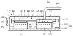
베이크 유닛(500)은 하우징(510), 이송 유닛(520), 가열 유닛(550), 냉각 유닛(570), 공정 챔버(580), 배기 부재(560)(560) 그리고 제어기(590)(590)를 포함한다.The
하우징(510)은 내부 공간을 제공한다. 내부 공간에서는 베이크 공정과 냉각 공정이 수행된다. 하우징(510)은 직육면체 형상으로 제공될 수 있다. 하우징(510)는 제1측벽(511), 제2측벽(513), 제3측벽(514), 그리고 제4측벽(515)을 포함한다.The
제1측벽(511)은 하우징(510)의 일측면에 제공된다. 제2측벽(513)은 제1측벽(511)과 맞은편에 제공된다. 하우징(510)의 측벽에는 기판(W)이 출입되는 출입구(512)가 형성된다. 일 예로 출입구(512)는 제1측벽(511)에 형성될 수 있다. 출입구(512)는 기판(W)이 이송 또는 반송 되도록 기판(W)의 이동하는 통로를 제공한다.The
제3측벽(514)은 제1측벽(511)과 제2측벽(513) 사이에 위치한다. 제3측벽(514)은 제1측벽(511)과 제2측벽(513)에 수직하게 제공된다. 제3측벽(514)의 길이는 제1측벽(513)의 길이보다 길게 제공될 수 있다.The
제4측벽(515)은 제3측벽(514)과 맞은편에 제공된다. 제4측벽(515)은 제1측벽(511)과 제2측벽(513) 사이에 위치한다. 제3측벽(514)과 제4측벽(515)은 서로 평행하게 제공된다. 제1측벽(511), 제2측벽(513), 제3측벽(514) 그리고 제4측벽(515)은 서로 동일한 높이로 제공될 수 있다.A
이송 유닛(520)은 기판(W)을 이송한다. 일 예로 이송 유닛(520)은 기판(W)을 가열 유닛(550으로 이송하거나, 공정이 끝난 기판(W)을 외부로 반송하도록 기판(W)을 이송시킨다. 이송 유닛(520)은 지지판(521), 이송암(522), 지지링(523), 그리고 구동기(527)를 포함한다.The
지지판(521)에는 기판(W)이 놓인다. 지지판(521)은 원형의 형상으로 제공된다. 지지판(521)은 원형의 플레이트로 제공될 수 있다. 지지판(521)은 기판(W)과 동일한 크기로 제공될 수 있다. 지지판(521)에는 가이드 홀(525)이 형성되어 있다. 가이드 홀(525)은 리프트 핀(553)을 수용하기 위한 공간이다. 가이드 홀(525)은 지지판(521)의 외측으로부터 그 내측으로 연장되어 제공된다. 가이드 홀(525)은 지지판(521)의 이동 시 리프트 핀(553)과 간섭 또는 충돌이 일어나지 않도록 한다.The substrate W is placed on the
이송암(522)은 지지판(521)과 고정결합된다. 이송암(522)은 지지판(521)과 구동기(527) 사이에 제공된다. 이송암(522)은 플레이트로 제공될 수 있다.The
지지링(523)은 지지판(521) 주위를 감싸며 제공된다. 지지링(523)은 지지판(521)의 가장 자리를 지지한다. 지지링(523)은 기판(W)이 지지판(521)에 놓여진 후 기판(W)이 정위치에 놓이도록 기판(W)을 지지하는 역할을 한다.The
구동기(527)는 지지판(521)를 이송 또는 반송할 수 있도록 한다. 구동기(527)는 지지판(521)를 직선 운동 또는 상하 구동할 수 있도록 제공된다. 구동기(527)는 지지판(521)를 출입구(512)와 가열 유닛(550) 사이로 이동시킬 수 있다.The
냉각 유닛(570)은 가열 처리가 끝난 기판(W)을 냉각시키는 역할을 한다. 냉각 유닛(570)은 냉각 플레이트(571)를 포함한다.The
냉각 플레이트(571)는 상부에서 바라 볼 때, 원형의 형상으로 제공된다. 냉각 플레이트(571)는 원통 형상으로 제공된다. 냉각 플레이트(571)의 상부에는 기판이 놓인다. 냉각 플레이트(571)의 내부에는 리프트 핀(553)이 제공되어 기판이 냉각 플레이트(571) 상에 놓이거나, 기판을 이송 유닛(520)으로 이송할 수 있다. 냉각 플레이트(571)의 내부에는 냉각 유체가 흐르는 냉각 유로가 제공될 수 있다. 냉각 유로에는 냉각수가 공급되어 기판(W)을 냉각 할 수 있다.The
공정 챔버(580)는 내부에 처리 공간(589)을 가진다. 공정 챔버(580)는 상부에서 바라 볼 때, 원형의 형상으로 제공된다. 공정 챔버(580)의 처리 공간(589)에서는 기판을 가열할 수 있다. 공정 챔버(580)는 상부 챔버(581)와 하부 챔버(583)를 포함한다.The
상부 챔버(581)는 원통형의 형상으로 제공된다. 하부 챔버(583)는 상부 챔버(581)와 접촉 가능하며, 상부 챔버(581)의 하부에 위치한다. 하부 챔버(583)는 원통형의 형상으로 제공된다. 처리 공간(589)은 상부 챔버(581)와 상부 챔버(581)가 접촉되어 형성된 내부의 공간이다.The
구동부재(585)는 상부 챔버(581) 또는 하부 챔버(583)와 연결되어 상부 챔버(581) 또는 하부 챔버(583)를 상하로 구동한다. 본 실시 예에는 구동부재(585)는 상부 챔버(581)와 연결된 예로 설명한다.The driving
구동부재(585)는 구동기(587)와 지지부(586)를 포함한다. 구동기(557)는 지지부(586)에 의해 상부 챔버(581)와 고정 결합된다. 구동기(587)는 기판(W)의 가열 유닛(550)으로 이송 또는 반송 되는 경우 상부 챔버(581)를 상하로 승하강시킨다. 구동기(587)는 기판 가열 공정 시 일정 시간 공정 챔버(580)를 개방 할 때, 상부 챔버(581)를 승강 시켜 공정 챔버(580)를 개방할 수 있다. 일 예로 구동기(587)는 실린더 구동기로 제공될 수 있다.The
상술한 예에서는 구동부재(585)가 상부 챔버(581)와 연결되어 제공되는 예로 설명하였으나, 이와는 달리, 하부 챔버(583)와 연결될 수도 있다. 선택적으로 구동부재(585)는 상부 챔버(581) 및 하부 챔버(583)와 연결되어 상부 챔버(581) 또는 하부 챔버(583)를 상하로 구동 시킬 수도 있다.In the above example, the driving
가열 유닛(550)은 기판(W)을 설정 온도로 가열한다. 가열 유닛(550)은 가열 플레이트(551), 히터(552) 그리고 리프트 핀(553)을 포함한다.The
가열 플레이트(551)의 내부에는 기판(W)을 가열하는 가열 수단이 제공된다. 가열 플레이트(551)에는 기판(W)이 놓인다. 가열 플레이트(551)는 원통의 형상으로 제공된다. 가열 플레이트(551)는 처리 공간(589) 내에 위치한다. 가열 플레이트(551)의 상부에는 리프트 핀(553)을 수용하는 핀 홀(554)이 형성되어 있다.Inside the
가열 플레이트(551) 내에는 히터(552)가 제공된다. 히터(552)는 가열 플레이트(551)를 가열하여 기판(W)을 가열한다. 이와는 달리 가열 수단으로 가열 플레이트(551)에 발열 패턴들이 제공될 수 있다.A
핀 홀(554)은 리프트 핀(553)이 기판(W)을 상하로 이동시킬 때 리프트 핀(553)의 이동하는 경로를 위해 제공된다. 핀 홀(554)은 가열 플레이트(551)의 상부에 제공되며, 복수개가 제공될 수 있다.The
리프트 핀(553)(554)은 승강 기구(미도시)에 의해 상하로 이동된다. 리프트 핀(553)(554)은 기판(W)을 가열 플레이트(551) 상에 안착시킬 수 있다. 리프트 핀(553)(554)은 기판(W)을 가열 플레이트(551)로부터 일정거리 이격된 위치로 기판(W)을 승강시킬 수 있다.The lift pins 553 and 554 are moved up and down by a lifting mechanism (not shown). The lift pins 553 and 554 can seat the substrate W on the
배기 부재(560)는 기판을 가열하는 공정 중 처리 공간(589)을 배기한다. 배기 부재(560)는 상부 챔버(581)의 중앙영역에 결합된다. 배기 부재(560)는 처리 공간(589)을 배기 압력을 제공하여 처리 공간(589)을 배기한다. 일 예로 배기 압력은 배기 부재(560)와 연결된 펌프(미도시) 등으로 제공될 수 있다.The
제어기(590)는 구동부재(585)와 리프트 핀(553)을 제어한다. 제어기(590)는 기판이 외부에서 이송 된 후 처리 공간(589)을 밀폐시키도록 구동부재(585)를 제어한다. 제어기(590)는 처리 공간(589)이 외부에 대해 닫혀진 상태에서 기판이 리프트 핀(553)에 의해 지지되어 가열 플레이트(551)의 상부로 이격되게 제공되는 공정 준비 단계(S100)와 상부 챔버(581) 또는 하부 챔버(583)의 상하 방향으로 이동에 의해 처리 공간(589)이 외부에 대해 설정시간 개방되게 제공되고 리프트 핀(553)이 하강하여 기판이 가열 플레이트(551)에 놓여지는 제1공정 단계(S110)와 기판이 가열 플레이트(551)에 놓인 상태가 유지되면서, 상부 챔버(581) 또는 하부 챔버(583)의 상하 방향으로 이동에 의해 처리 공간(589)이 외부에 대해 닫혀지는 제2공정 단계(S120)를 수행하도록 구동부재(585)와 리프트 핀(553)을 제어한다.The
현상 모듈(402)은 기판(W) 상에 패턴을 얻기 위해 현상액을 공급하여 포토 레지스트의 일부를 제거하는 현상 공정, 및 현상 공정 전후에 기판(W)에 대해 수행되는 가열 및 냉각과 같은 열처리 공정을 포함한다. 현상모듈(402)은 액처리 챔버(460), 베이크 유닛(470), 그리고 반송 챔버(480)를 가진다. 액처리 챔버(460), 베이크 유닛(500), 그리고 반송 챔버(480)는 제2방향(14)을 따라 순차적으로 배치된다. 액처리 챔버(460)는 현상 챔버로 제공될 수 있다. 현상 챔버(460)와 베이크 유닛(500)는 반송 챔버(480)를 사이에 두고 제2방향(14)으로 서로 이격되게 위치된다. 현상 챔버(460)는 복수 개가 제공되며, 제1방향(12) 및 제3방향(16)으로 각각 복수 개씩 제공된다.The developing
반송 챔버(480)는 제 1 버퍼 모듈(300)의 제 2 버퍼(330)와 제1방향(12)으로 나란하게 위치된다. 반송 챔버(480) 내에는 현상부 로봇(482)과 가이드 레일(483)이 위치된다. 반송 챔버(480)는 대체로 직사각의 형상을 가진다. 현상부 로봇(482)은 베이크 유닛들(470), 현상 챔버들(460), 그리고 제 1 버퍼 모듈(300)의 제 2 버퍼(330)와 냉각 챔버(350) 간에 기판(W)를 이송한다. 가이드 레일(483)은 그 길이 방향이 제1방향(12)과 나란하도록 배치된다. 가이드 레일(483)은 현상부 로봇(482)이 제1방향(12)으로 직선 이동되도록 안내한다. 현상부 로봇(482)은 핸드(484), 아암(485), 지지대(486), 그리고 받침대(487)를 가진다. 핸드(484)는 아암(485)에 고정 설치된다. 아암(485)은 신축 가능한 구조로 제공되어 핸드(484)가 수평 방향으로 이동 가능하도록 한다. 지지대(486)는 그 길이 방향이 제3방향(16)을 따라 배치되도록 제공된다. 아암(485)은 지지대(486)를 따라 제3방향(16)으로 직선 이동 가능하도록 지지대(486)에 결합된다. 지지대(486)는 받침대(487)에 고정 결합된다. 받침대(487)는 가이드 레일(483)을 따라 이동 가능하도록 가이드 레일(483)에 결합된다.The
현상 챔버들(460)은 모두 동일한 구조를 가진다. 다만, 각각의 현상 챔버(460)에서 사용되는 현상액의 종류는 서로 상이할 수 있다. 현상 챔버(460)는 기판(W) 상의 포토 레지스트 중 광이 조사된 영역을 제거한다. 이때, 보호막 중 광이 조사된 영역도 같이 제거된다. 선택적으로 사용되는 포토 레지스트의 종류에 따라 포토 레지스트 및 보호막의 영역들 중 광이 조사되지 않은 영역만이 제거될 수 있다.The
현상 챔버(460)는 하우징(461), 지지 플레이트(462), 그리고 노즐(463)을 가진다. 하우징(461)은 상부가 개방된 컵 형상을 가진다. 지지 플레이트(462)는 하우징(461) 내에 위치되며, 기판(W)를 지지한다. 지지 플레이트(462)는 회전 가능하게 제공된다. 노즐(463)은 지지 플레이트(462)에 놓인 기판(W) 상으로 현상액을 공급한다. 노즐(463)은 원형의 관 형상을 가지고, 기판(W)의 중심으로 현상액 공급할 수 있다. 선택적으로 노즐(463)은 기판(W)의 직경에 상응하는 길이를 가지고, 노즐(463)의 토출구는 슬릿으로 제공될 수 있다. 또한, 현상 챔버(460)에는 추가적으로 현상액이 공급된 기판(W) 표면을 세정하기 위해 탈이온수와 같은 세정액을 공급하는 노즐(464)이 더 제공될 수 있다.The
현상 모듈(402)에 제공되는 베이크 유닛(500)은 전술한 베이크 유닛(500)과 대체로 동일하게 제공된다.The
상술한 바와 같이 도포 및 현상 모듈(400)에서 도포 모듈(401)과 현상 모듈(402)은 서로 간에 분리되도록 제공된다. 또한, 상부에서 바라볼 때 도포 모듈(401)과 현상 모듈(402)은 동일한 챔버 배치를 가질 수 있다.As described above, in the application and
인터페이스 모듈(700)은 기판(W)을 이송한다. 인터페이스 모듈(700)은 프레임(710), 제 1 버퍼(720), 제 2 버퍼(730), 그리고 인터페이스 로봇(740)를 포함한다. 제 1 버퍼(720), 제 2 버퍼(730), 그리고 인터페이스 로봇(740)은 프레임(710) 내에 위치된다. 제 1 버퍼(720)와 제 2 버퍼(730)는 서로 간에 일정거리 이격되며, 서로 적층되게 배치된다. 제 1 버퍼(720)는 제 2 버퍼(730)보다 높게 배치된다.The
인터페이스 로봇(740)은 제 1 버퍼(720) 및 제 2 버퍼(730)와 제2방향(14)으로 이격되게 위치된다. 인터페이스 로봇(740)은 제 1 버퍼(720), 제 2 버퍼(730), 그리고 노광 장치(900) 간에 기판(W)을 운반한다.The
제 1 버퍼(720)는 공정이 수행된 기판(W)들이 노광 장치(900)로 이동되기 전에 이들을 일시적으로 보관한다. 그리고 제 2 버퍼(730)는 노광 장치(900)에서 공정이 완료된 기판(W)들이 이동되기 전에 이들을 일시적으로 보관한다. 제 1 버퍼(720)는 하우징(721)과 복수의 지지대들(722)을 가진다. 지지대들(722)은 하우징(721) 내에 배치되며, 서로 간에 제3방향(16)을 따라 이격되게 제공된다. 각각의 지지대(722)에는 하나의 기판(W)이 놓인다. 하우징(721)은 인터페이스 로봇(740) 및 전처리 로봇(632)이 하우징(721) 내로 지지대(722)에 기판(W)를 반입 또는 반출할 수 있도록 인터페이스 로봇(740)이 제공된 방향 및 전처리 로봇(632)이 제공된 방향에 개구를 가진다. 제 2 버퍼(730)는 제 1 버퍼(720)와 유사한 구조를 가진다. 인터페이스 모듈에는 웨이퍼에 대해 소정의 공정을 수행하는 챔버의 제공 없이 상술한 바와 같이 버퍼들 및 로봇만 제공될 수 있다.The
이하에서는 본 발명의 일 실시 예에 따른 기판 가열 방법(S10)을 설명한다.Hereinafter, a substrate heating method (S10) according to an embodiment of the present invention will be described.
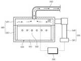
도 8은 본 발명의 일 실시 예에 따른 기판 가열 방법을 순차적으로 보여주는 플로우 차트이고, 도 9 내지 도 11은 본 발명의 일 실시 예에 따른 기판 가열 방법을 순차적으로 보여주는 도면이다. 도 8 내지 도 11을 참고하면, 기판 가열 방법(S10)은 공정 준비 단계(S100), 제1공정 단계(S110) 그리고 제2공정 단계(S120)를 포함한다.FIG. 8 is a flowchart sequentially illustrating a method for heating a substrate according to an embodiment of the present invention. FIGS. 9 to 11 are views sequentially illustrating a method for heating a substrate according to an embodiment of the present invention. 8 to 11, the substrate heating method S10 includes a process preparation step S100, a first process step S110 and a second process step S120.
공정 준비 단계(S100)는 기판을 가열하기 위한 공정을 준비하는 단계이다. 도 9와 같이 공정 준비 단계(S100)는 상부 챔버(581)와 하부 챔버(583)가 접촉되어 정의된 처리 공간(589)에 외부에 대해 닫혀진 상태을 유지한다. 공정 준비 단계(S100)는 처리 공간(589)이 밀폐된 상태에서 기판이 리프트 핀(553)에 의해 지지되어 가열 플레이트(551)의 상부로 이격되게 제공된다.The process preparation step (SlOO) is a step of preparing a process for heating the substrate. As shown in FIG. 9, in the process preparation step (S100), the
제1공정 단계(S110)에서는 기판을 가열하는 단계이다. 도 10과 같이 제1공정 단계(S110)에서는 상부 챔버(581) 또는 하부 챔버(583)에 상하 방향으로 이동에 의해 처리 공간(589)이 외부에 대해 설정시간 개방되게 제공되고, 리프프 핀의 하강하여 기판이 가열 플레이트(551)에 놓여지는 단계이다. 제1공전 진행 단계에서는 배기 부재(560)에 의해 처리 공간(589)에 배기가 이루어진다. 기판을 가열 플레이트(551)에서 가열이 이루어지며, 일정시간 동안 개방된 상태를 유지한다.In the first process step (S110), the substrate is heated. 10, in the first process step S110, the
제2공정 단계(S120)는 기판이 가열 플레이트(551)에 놓인 상태가 유지된다. 제2공정 단계(S120)에서는 도 11과 같이 상부 챔버(581) 또는 하부 챔버(583)의 상하 방향으로 이동에 의해 처리 공간(589)이 외부에 대해 닫혀진다. 처리 공간(589)이 밀폐된 상태에서 기판의 가열을 계속해서 이루어지며 기판 가열 공정을 수행한다. 제2공정 단계(S120)에서는 배기 부재(560)에 의해 처리 공간(589)의 배기가 이루어진다.In the second process step S120, the substrate is kept in a state of being placed on the
기판 가열 공정이 끝난 후 처리 공간(589)이 개방되고 이송 유닛에 의해 기판은 냉각 공정을 겪거나 또는 외부로 반송된다.After the substrate heating process is finished, the
도 12는 일반적인 기판 가열 공정 시 기판의 영역별 처리액의 두께를 개략적으로 보여주는 그래프이고, 도 13은 본 발명의 일 실시 예에 따른 기판 가열 방법 시 기판의 영역별 처리액의 두께를 개략적으로 보여주는 그래프이다. FIG. 12 is a graph schematically showing the thickness of the treatment liquid for each region of the substrate during a general substrate heating process, and FIG. 13 is a graph showing the thickness of the treatment liquid for each region of the substrate in a substrate heating method according to an embodiment of the present invention. Graph.
도 12와 도 13을 참고하면, 기판을 가열 하는 공정 시 밀폐된 처리 공간(589)에 배기 과정을 함께 수행하여 공정이 이루어지는 경우 도 12와 같이 기판의 중앙영역(C)과 기판의 가장자리 영역(E)의 처리액의 두께가 다른 영역에 비해 일정치 않다. 기판의 영역별(C,E)로 처리액의 두께가 차이가 나면 베이크 공정에 효율이 떨어지게 된다.Referring to FIGS. 12 and 13, when the process is performed by performing the evacuation process in the
이와는 달리, 본 발명의 기판 가열 방법의 경우 기판을 가열 시 처리 공간(589)을 일정시간 개방하여 수행되는 경우 도 13과 같이 기판의 전체 영역(C,E)에서 처리액의 두께가 균일하게 나타난다. 처리액의 두께가 기판의 영역별(C,E)로 균일하여 베이크 공정의 효율이 향상된다. 이러한, 처리액의 두께 차이는 일정 시간 처리 공간(589)을 개방하여 배기 시 중앙영역(C)으로 기류의 흐름이 몰려 기판의 가장 자리 영역(E)과 기판의 중앙 영역(C)에 처리액의 두께가 일정치 않는 현상이 해소된 것이다.On the contrary, in the case of the substrate heating method of the present invention, when the substrate is heated by opening the
이상의 상세한 설명은 본 발명을 예시하는 것이다. 또한 전술한 내용은 본 발명의 바람직한 실시 형태를 나타내어 설명하는 것이며, 본 발명은 다양한 다른 조합, 변경 및 환경에서 사용할 수 있다. 즉 본 명세서에 개시된 발명의 개념의 범위, 저술한 개시 내용과 균등한 범위 및/또는 당업계의 기술 또는 지식의 범위내에서 변경 또는 수정이 가능하다. 저술한 실시예는 본 발명의 기술적 사상을 구현하기 위한 최선의 상태를 설명하는 것이며, 본 발명의 구체적인 적용 분야 및 용도에서 요구되는 다양한 변경도 가능하다. 따라서 이상의 발명의 상세한 설명은 개시된 실시 상태로 본 발명을 제한하려는 의도가 아니다. 또한 첨부된 청구범위는 다른 실시 상태도 포함하는 것으로 해석되어야 한다.The foregoing detailed description is illustrative of the present invention. In addition, the foregoing is intended to illustrate and explain the preferred embodiments of the present invention, and the present invention may be used in various other combinations, modifications, and environments. That is, it is possible to make changes or modifications within the scope of the concept of the invention disclosed in this specification, within the scope of the disclosure, and / or within the skill and knowledge of the art. The embodiments described herein are intended to illustrate the best mode for implementing the technical idea of the present invention and various modifications required for specific applications and uses of the present invention are also possible. Accordingly, the detailed description of the invention is not intended to limit the invention to the disclosed embodiments. It is also to be understood that the appended claims are intended to cover such other embodiments.
500: 베이크 유닛510: 하우징
520: 이송 유닛550; 가열 유닛
551: 가열 플레이트580: 공정 챔버
581: 상부 챔버583: 하부 챔버
585: 구동부재560: 배기 부재
590: 제어기500: bake unit 510: housing
520:
551: Heating plate 580: Process chamber
581: upper chamber 583: lower chamber
585: driving member 560: exhaust member
590:
Claims (10)
Translated fromKorean상부 챔버와 하부 챔버가 접촉되어 상기 상부 챔버와 상기 하부 챔버에 의해 정의된 처리 공간이 외부에 대해 닫혀진 상태에서 기판이 리프트 핀에 의해 지지되어 가열 플레이트의 상부로 이격되게 제공되는 공정 준비 단계와;
상기 기판의 전체 영역에서 처리액의 두께가 균일하게 유지되도록, 상기 상부 챔버 또는 상기 하부 챔버의 상하 방향으로 이동에 의해 상기 처리 공간이 외부에 대해 설정시간 개방되게 제공되고 상기 리프트 핀이 하강하여 상기 기판이 상기 가열 플레이트에 놓여져서 상기 기판이 가열되며, 상기 처리 공간에 배기가 이루어지는 제1공정 단계와; 그리고
상기 기판이 상기 가열 플레이트에 놓인 상태가 유지되어 상기 기판이 가열되면서, 상기 상부 챔버 또는 상기 하부 챔버의 상하 방향으로 이동에 의해 상기 처리 공간이 외부에 대해 닫혀지며, 상기 처리 공간에 배기가 이루어지는 제2공정 단계를 포함하는 기판 가열 방법.
A method of heating a substrate,
A process preparation step in which the upper chamber and the lower chamber are in contact with each other and the processing space defined by the upper chamber and the lower chamber is closed with respect to the outside so that the substrate is supported by the lift pins and spaced apart from the upper portion of the heating plate;
The processing space is provided with a predetermined time to the outside by moving in the vertical direction of the upper chamber or the lower chamber so that the thickness of the processing liquid in the entire region of the substrate is uniformly maintained, A first processing step in which a substrate is placed on the heating plate to heat the substrate, and the processing space is evacuated; And
Wherein the processing chamber is closed with respect to the outside by moving the upper chamber or the lower chamber in a vertical direction while the substrate is held on the heating plate and the substrate is heated, 2 < / RTI > process step.
상기 처리 공간에 배기는 상기 상부 챔버의 중앙 영역을 통해 이루어지는 기판 가열 방법.
The method according to claim 1,
And exhausting the processing space through a central region of the upper chamber.
상기 가열 플레이트는 상기 하부 챔버에 제공되는 기판 가열 방법.
The method according to claim 1,
Wherein the heating plate is provided in the lower chamber.
상부 챔버와 하부 챔버가 접촉되어 상기 상부 챔버와 상기 하부 챔버에 의해 정의된 처리 공간을 가지는 공정 챔버와;
상기 처리 공간에 위치하며 기판을 가열하는 가열 플레이트와;
상기 가열 플레이트에 기판을 내려놓거나, 상기 가열 플레이트 상에 놓인 기판을 상기 가열 플레이트와 이격되도록 이동시키는 리프트 핀과;
상기 상부 챔버 또는 상기 하부 챔버와 연결되어 상기 상부 챔버 또는 상기 하부 챔버를 상하로 구동하는 구동부재와;
상기 상부 챔버의 중앙영역과 연결되어, 상기 처리 공간을 배기하는 배기 부재와; 그리고
상기 구동부재, 상기 리프트 핀 및 상기 배기 부재를 제어하는 제어기를 포함하되,
상기 제어기는 상기 처리 공간이 외부에 대해 닫혀진 상태에서 기판이 리프트 핀에 의해 지지되어 가열 플레이트의 상부로 이격되게 제공되는 공정 준비 단계와 상기 기판의 전체 영역에서 처리액의 두께가 균일하게 유지되도록, 상기 상부 챔버 또는 상기 하부 챔버의 상하 방향으로 이동에 의해 상기 처리 공간이 외부에 대해 설정시간 개방되게 제공되고 상기 리프트 핀이 하강하여 상기 기판이 상기 가열 플레이트에 놓여져서 상기 기판이 가열되며, 상기 처리 공간에 배기가 이루어지는 제1공정 단계와 상기 기판이 상기 가열 플레이트에 놓인 상태가 유지되어 상기 기판이 가열되면서, 상기 상부 챔버 또는 상기 하부 챔버의 상하 방향으로 이동에 의해 상기 처리 공간이 외부에 대해 닫혀지며, 상기 처리 공간에 배기가 이루어지는 제2공정 단계를 수행하도록 상기 구동부재와 상기 리프트 핀을 제어하는 기판 처리 장치.
An apparatus for processing a substrate,
A process chamber in contact with the upper chamber and the lower chamber and having a processing space defined by the upper chamber and the lower chamber;
A heating plate located in the processing space and heating the substrate;
A lift pin for lowering the substrate on the heating plate or moving the substrate placed on the heating plate away from the heating plate;
A driving member connected to the upper chamber or the lower chamber to drive the upper chamber or the lower chamber up and down;
An exhaust member connected to a central region of the upper chamber to exhaust the processing space; And
And a controller for controlling the driving member, the lift pin, and the exhaust member,
The controller comprising a process preparation step in which the substrate is supported by a lift pin and spaced apart from the top of the heating plate in a state where the processing space is closed with respect to the outside and a process step in which the thickness of the processing solution is uniformly maintained in the entire area of the substrate, By moving in the vertical direction of the upper chamber or the lower chamber, the processing space is provided to be opened for a predetermined time with respect to the outside, and the lift pins are lowered so that the substrate is placed on the heating plate to heat the substrate, A first process step in which exhaust is performed in the space, and the processing space is closed with respect to the outside by moving the upper chamber or the lower chamber in the vertical direction while the substrate is held on the heating plate and the substrate is heated And a second process step of exhausting the processing space A substrate processing apparatus for controlling the drive member and the lift pins to perform.
상기 리프트 핀은 상기 가열 플레이트에 형성된 핀 홀 내에 상하로 이동가능하게 제공되는 기판 처리 장치.
The method according to claim 6,
Wherein the lift pins are provided so as to be movable up and down in pin holes formed in the heating plate.
Priority Applications (1)
| Application Number | Priority Date | Filing Date | Title |
|---|---|---|---|
| KR1020150146869AKR101776018B1 (en) | 2015-10-21 | 2015-10-21 | Method for heating a substrate and Apparatus for treating a substrate |
Applications Claiming Priority (1)
| Application Number | Priority Date | Filing Date | Title |
|---|---|---|---|
| KR1020150146869AKR101776018B1 (en) | 2015-10-21 | 2015-10-21 | Method for heating a substrate and Apparatus for treating a substrate |
Publications (2)
| Publication Number | Publication Date |
|---|---|
| KR20170046474A KR20170046474A (en) | 2017-05-02 |
| KR101776018B1true KR101776018B1 (en) | 2017-09-07 |
Family
ID=58742735
Family Applications (1)
| Application Number | Title | Priority Date | Filing Date |
|---|---|---|---|
| KR1020150146869AActiveKR101776018B1 (en) | 2015-10-21 | 2015-10-21 | Method for heating a substrate and Apparatus for treating a substrate |
Country Status (1)
| Country | Link |
|---|---|
| KR (1) | KR101776018B1 (en) |
Cited By (1)
| Publication number | Priority date | Publication date | Assignee | Title |
|---|---|---|---|---|
| US11139184B2 (en) | 2017-10-17 | 2021-10-05 | Semes Co., Ltd. | Method and apparatus for treating substrate |
Citations (1)
| Publication number | Priority date | Publication date | Assignee | Title |
|---|---|---|---|---|
| JP2001237155A (en)* | 2000-02-21 | 2001-08-31 | Tokyo Electron Ltd | Heat treatment method and heat treatment device |
- 2015
- 2015-10-21KRKR1020150146869Apatent/KR101776018B1/enactiveActive
Patent Citations (1)
| Publication number | Priority date | Publication date | Assignee | Title |
|---|---|---|---|---|
| JP2001237155A (en)* | 2000-02-21 | 2001-08-31 | Tokyo Electron Ltd | Heat treatment method and heat treatment device |
Cited By (1)
| Publication number | Priority date | Publication date | Assignee | Title |
|---|---|---|---|---|
| US11139184B2 (en) | 2017-10-17 | 2021-10-05 | Semes Co., Ltd. | Method and apparatus for treating substrate |
Also Published As
| Publication number | Publication date |
|---|---|
| KR20170046474A (en) | 2017-05-02 |
Similar Documents
| Publication | Publication Date | Title |
|---|---|---|
| KR20160017699A (en) | Bake unit, substrate treating apparatus including the unit, and substrate treating method | |
| KR101605721B1 (en) | Bake apparatus and Apparatus for treating substrate | |
| KR20180000928A (en) | unit for treating substrate and bake apparatus a having the unit and method processing substrate by using thereof | |
| KR20220034304A (en) | Bake unit and Apparatus for treating substrate | |
| KR20190012965A (en) | Apparatus and Method for treating substrate | |
| KR102516725B1 (en) | bake apparatus a having the unit and method processing substrate by using thereof | |
| KR102315662B1 (en) | Substrate treating apparatus and method | |
| KR102397846B1 (en) | Apparatus for treating a substrate | |
| KR20220021290A (en) | Apparatus for treating substrate | |
| KR20160081010A (en) | Bake unit, substrate treating apparatus including the unit, and substrate treating method | |
| KR101776018B1 (en) | Method for heating a substrate and Apparatus for treating a substrate | |
| KR20170024211A (en) | Unit for supporting substrate, Apparatus for treating substrate, and Method for treating substrate | |
| KR101935940B1 (en) | Apparatus and Method for treating substrate | |
| KR102000023B1 (en) | Substrate treating apparatus | |
| KR101909183B1 (en) | Apparatus for treating substrate | |
| KR102378336B1 (en) | Bake apparatus and bake method | |
| KR101909481B1 (en) | Bake unit, Apparatus and method for treating substrate with the unit | |
| KR102224987B1 (en) | Heat processing apparatus | |
| KR20180054948A (en) | Apparatus anf Method for treating substrate | |
| KR101914482B1 (en) | Substrate treating apparatus and substrate treating method | |
| KR20160134926A (en) | Method for applying a liquid and apparatus for treating a substrate | |
| KR101885567B1 (en) | Apparatus treating substrate | |
| KR101909185B1 (en) | Substrate treating apparatus and substrate treating method | |
| KR101768518B1 (en) | Transfer chamber, Apparatus for treating substrate, and method for trasnferring substrate | |
| KR102156897B1 (en) | Apparatus and Method for treating substrate |
Legal Events
| Date | Code | Title | Description |
|---|---|---|---|
| A201 | Request for examination | ||
| PA0109 | Patent application | Patent event code:PA01091R01D Comment text:Patent Application Patent event date:20151021 | |
| PA0201 | Request for examination | ||
| E902 | Notification of reason for refusal | ||
| PE0902 | Notice of grounds for rejection | Comment text:Notification of reason for refusal Patent event date:20161111 Patent event code:PE09021S01D | |
| PG1501 | Laying open of application | ||
| E601 | Decision to refuse application | ||
| PE0601 | Decision on rejection of patent | Patent event date:20170530 Comment text:Decision to Refuse Application Patent event code:PE06012S01D Patent event date:20161111 Comment text:Notification of reason for refusal Patent event code:PE06011S01I | |
| AMND | Amendment | ||
| PX0901 | Re-examination | Patent event code:PX09011S01I Patent event date:20170530 Comment text:Decision to Refuse Application | |
| PX0701 | Decision of registration after re-examination | Patent event date:20170830 Comment text:Decision to Grant Registration Patent event code:PX07013S01D Patent event date:20170731 Comment text:Amendment to Specification, etc. Patent event code:PX07012R01I Patent event date:20170530 Comment text:Decision to Refuse Application Patent event code:PX07011S01I | |
| X701 | Decision to grant (after re-examination) | ||
| GRNT | Written decision to grant | ||
| PR0701 | Registration of establishment | Comment text:Registration of Establishment Patent event date:20170901 Patent event code:PR07011E01D | |
| PR1002 | Payment of registration fee | Payment date:20170904 End annual number:3 Start annual number:1 | |
| PG1601 | Publication of registration | ||
| PR1001 | Payment of annual fee | Payment date:20200821 Start annual number:4 End annual number:4 | |
| PR1001 | Payment of annual fee | Payment date:20210701 Start annual number:5 End annual number:5 | |
| PR1001 | Payment of annual fee | Payment date:20220824 Start annual number:6 End annual number:6 | |
| PR1001 | Payment of annual fee | Payment date:20230823 Start annual number:7 End annual number:7 | |
| PR1001 | Payment of annual fee | Payment date:20240823 Start annual number:8 End annual number:8 |