KR101774052B1 - Connector Of Electric Vehicle Charger - Google Patents
Connector Of Electric Vehicle ChargerDownload PDFInfo
- Publication number
- KR101774052B1 KR101774052B1KR1020110026820AKR20110026820AKR101774052B1KR 101774052 B1KR101774052 B1KR 101774052B1KR 1020110026820 AKR1020110026820 AKR 1020110026820AKR 20110026820 AKR20110026820 AKR 20110026820AKR 101774052 B1KR101774052 B1KR 101774052B1
- Authority
- KR
- South Korea
- Prior art keywords
- terminal housing
- connector
- lever
- latch
- electric vehicle
- Prior art date
- Legal status (The legal status is an assumption and is not a legal conclusion. Google has not performed a legal analysis and makes no representation as to the accuracy of the status listed.)
- Active
Links
Images


Classifications
- H—ELECTRICITY
- H01—ELECTRIC ELEMENTS
- H01R—ELECTRICALLY-CONDUCTIVE CONNECTIONS; STRUCTURAL ASSOCIATIONS OF A PLURALITY OF MUTUALLY-INSULATED ELECTRICAL CONNECTING ELEMENTS; COUPLING DEVICES; CURRENT COLLECTORS
- H01R13/00—Details of coupling devices of the kinds covered by groups H01R12/70 or H01R24/00 - H01R33/00
- H01R13/62—Means for facilitating engagement or disengagement of coupling parts or for holding them in engagement
- H01R13/629—Additional means for facilitating engagement or disengagement of coupling parts, e.g. aligning or guiding means, levers, gas pressure electrical locking indicators, manufacturing tolerances
- B—PERFORMING OPERATIONS; TRANSPORTING
- B60—VEHICLES IN GENERAL
- B60L—PROPULSION OF ELECTRICALLY-PROPELLED VEHICLES; SUPPLYING ELECTRIC POWER FOR AUXILIARY EQUIPMENT OF ELECTRICALLY-PROPELLED VEHICLES; ELECTRODYNAMIC BRAKE SYSTEMS FOR VEHICLES IN GENERAL; MAGNETIC SUSPENSION OR LEVITATION FOR VEHICLES; MONITORING OPERATING VARIABLES OF ELECTRICALLY-PROPELLED VEHICLES; ELECTRIC SAFETY DEVICES FOR ELECTRICALLY-PROPELLED VEHICLES
- B60L53/00—Methods of charging batteries, specially adapted for electric vehicles; Charging stations or on-board charging equipment therefor; Exchange of energy storage elements in electric vehicles
- B60L53/10—Methods of charging batteries, specially adapted for electric vehicles; Charging stations or on-board charging equipment therefor; Exchange of energy storage elements in electric vehicles characterised by the energy transfer between the charging station and the vehicle
- B60L53/14—Conductive energy transfer
- B60L53/16—Connectors, e.g. plugs or sockets, specially adapted for charging electric vehicles
- B—PERFORMING OPERATIONS; TRANSPORTING
- B60—VEHICLES IN GENERAL
- B60L—PROPULSION OF ELECTRICALLY-PROPELLED VEHICLES; SUPPLYING ELECTRIC POWER FOR AUXILIARY EQUIPMENT OF ELECTRICALLY-PROPELLED VEHICLES; ELECTRODYNAMIC BRAKE SYSTEMS FOR VEHICLES IN GENERAL; MAGNETIC SUSPENSION OR LEVITATION FOR VEHICLES; MONITORING OPERATING VARIABLES OF ELECTRICALLY-PROPELLED VEHICLES; ELECTRIC SAFETY DEVICES FOR ELECTRICALLY-PROPELLED VEHICLES
- B60L53/00—Methods of charging batteries, specially adapted for electric vehicles; Charging stations or on-board charging equipment therefor; Exchange of energy storage elements in electric vehicles
- B60L53/30—Constructional details of charging stations
- B60L53/305—Communication interfaces
- B—PERFORMING OPERATIONS; TRANSPORTING
- B60—VEHICLES IN GENERAL
- B60L—PROPULSION OF ELECTRICALLY-PROPELLED VEHICLES; SUPPLYING ELECTRIC POWER FOR AUXILIARY EQUIPMENT OF ELECTRICALLY-PROPELLED VEHICLES; ELECTRODYNAMIC BRAKE SYSTEMS FOR VEHICLES IN GENERAL; MAGNETIC SUSPENSION OR LEVITATION FOR VEHICLES; MONITORING OPERATING VARIABLES OF ELECTRICALLY-PROPELLED VEHICLES; ELECTRIC SAFETY DEVICES FOR ELECTRICALLY-PROPELLED VEHICLES
- B60L53/00—Methods of charging batteries, specially adapted for electric vehicles; Charging stations or on-board charging equipment therefor; Exchange of energy storage elements in electric vehicles
- B60L53/30—Constructional details of charging stations
- B60L53/31—Charging columns specially adapted for electric vehicles
- H—ELECTRICITY
- H01—ELECTRIC ELEMENTS
- H01R—ELECTRICALLY-CONDUCTIVE CONNECTIONS; STRUCTURAL ASSOCIATIONS OF A PLURALITY OF MUTUALLY-INSULATED ELECTRICAL CONNECTING ELEMENTS; COUPLING DEVICES; CURRENT COLLECTORS
- H01R27/00—Coupling parts adapted for co-operation with two or more dissimilar counterparts
- H—ELECTRICITY
- H01—ELECTRIC ELEMENTS
- H01R—ELECTRICALLY-CONDUCTIVE CONNECTIONS; STRUCTURAL ASSOCIATIONS OF A PLURALITY OF MUTUALLY-INSULATED ELECTRICAL CONNECTING ELEMENTS; COUPLING DEVICES; CURRENT COLLECTORS
- H01R31/00—Coupling parts supported only by co-operation with counterpart
- H01R31/06—Intermediate parts for linking two coupling parts, e.g. adapter
- H—ELECTRICITY
- H02—GENERATION; CONVERSION OR DISTRIBUTION OF ELECTRIC POWER
- H02J—CIRCUIT ARRANGEMENTS OR SYSTEMS FOR SUPPLYING OR DISTRIBUTING ELECTRIC POWER; SYSTEMS FOR STORING ELECTRIC ENERGY
- H02J7/00—Circuit arrangements for charging or depolarising batteries or for supplying loads from batteries
- Y—GENERAL TAGGING OF NEW TECHNOLOGICAL DEVELOPMENTS; GENERAL TAGGING OF CROSS-SECTIONAL TECHNOLOGIES SPANNING OVER SEVERAL SECTIONS OF THE IPC; TECHNICAL SUBJECTS COVERED BY FORMER USPC CROSS-REFERENCE ART COLLECTIONS [XRACs] AND DIGESTS
- Y02—TECHNOLOGIES OR APPLICATIONS FOR MITIGATION OR ADAPTATION AGAINST CLIMATE CHANGE
- Y02T—CLIMATE CHANGE MITIGATION TECHNOLOGIES RELATED TO TRANSPORTATION
- Y02T10/00—Road transport of goods or passengers
- Y02T10/60—Other road transportation technologies with climate change mitigation effect
- Y02T10/70—Energy storage systems for electromobility, e.g. batteries
- Y—GENERAL TAGGING OF NEW TECHNOLOGICAL DEVELOPMENTS; GENERAL TAGGING OF CROSS-SECTIONAL TECHNOLOGIES SPANNING OVER SEVERAL SECTIONS OF THE IPC; TECHNICAL SUBJECTS COVERED BY FORMER USPC CROSS-REFERENCE ART COLLECTIONS [XRACs] AND DIGESTS
- Y02—TECHNOLOGIES OR APPLICATIONS FOR MITIGATION OR ADAPTATION AGAINST CLIMATE CHANGE
- Y02T—CLIMATE CHANGE MITIGATION TECHNOLOGIES RELATED TO TRANSPORTATION
- Y02T10/00—Road transport of goods or passengers
- Y02T10/60—Other road transportation technologies with climate change mitigation effect
- Y02T10/7072—Electromobility specific charging systems or methods for batteries, ultracapacitors, supercapacitors or double-layer capacitors
- Y—GENERAL TAGGING OF NEW TECHNOLOGICAL DEVELOPMENTS; GENERAL TAGGING OF CROSS-SECTIONAL TECHNOLOGIES SPANNING OVER SEVERAL SECTIONS OF THE IPC; TECHNICAL SUBJECTS COVERED BY FORMER USPC CROSS-REFERENCE ART COLLECTIONS [XRACs] AND DIGESTS
- Y02—TECHNOLOGIES OR APPLICATIONS FOR MITIGATION OR ADAPTATION AGAINST CLIMATE CHANGE
- Y02T—CLIMATE CHANGE MITIGATION TECHNOLOGIES RELATED TO TRANSPORTATION
- Y02T90/00—Enabling technologies or technologies with a potential or indirect contribution to GHG emissions mitigation
- Y02T90/10—Technologies relating to charging of electric vehicles
- Y02T90/12—Electric charging stations
- Y—GENERAL TAGGING OF NEW TECHNOLOGICAL DEVELOPMENTS; GENERAL TAGGING OF CROSS-SECTIONAL TECHNOLOGIES SPANNING OVER SEVERAL SECTIONS OF THE IPC; TECHNICAL SUBJECTS COVERED BY FORMER USPC CROSS-REFERENCE ART COLLECTIONS [XRACs] AND DIGESTS
- Y02—TECHNOLOGIES OR APPLICATIONS FOR MITIGATION OR ADAPTATION AGAINST CLIMATE CHANGE
- Y02T—CLIMATE CHANGE MITIGATION TECHNOLOGIES RELATED TO TRANSPORTATION
- Y02T90/00—Enabling technologies or technologies with a potential or indirect contribution to GHG emissions mitigation
- Y02T90/10—Technologies relating to charging of electric vehicles
- Y02T90/14—Plug-in electric vehicles
- Y—GENERAL TAGGING OF NEW TECHNOLOGICAL DEVELOPMENTS; GENERAL TAGGING OF CROSS-SECTIONAL TECHNOLOGIES SPANNING OVER SEVERAL SECTIONS OF THE IPC; TECHNICAL SUBJECTS COVERED BY FORMER USPC CROSS-REFERENCE ART COLLECTIONS [XRACs] AND DIGESTS
- Y02—TECHNOLOGIES OR APPLICATIONS FOR MITIGATION OR ADAPTATION AGAINST CLIMATE CHANGE
- Y02T—CLIMATE CHANGE MITIGATION TECHNOLOGIES RELATED TO TRANSPORTATION
- Y02T90/00—Enabling technologies or technologies with a potential or indirect contribution to GHG emissions mitigation
- Y02T90/10—Technologies relating to charging of electric vehicles
- Y02T90/16—Information or communication technologies improving the operation of electric vehicles
Landscapes
- Engineering & Computer Science (AREA)
- Power Engineering (AREA)
- Transportation (AREA)
- Mechanical Engineering (AREA)
- Electric Propulsion And Braking For Vehicles (AREA)
- Details Of Connecting Devices For Male And Female Coupling (AREA)
Abstract
Translated fromKoreanDescription
Translated fromKorean본 발명은 전기 자동차 충전장치의 커넥터에 관한 것이다. 보다 상세하게, 본 발명은 커넥터의 구조를 개선하여 구조를 단순화하고 부품의 수가 최소화되며, 장착과정, 충전과정 및 탈착과정에서의 신뢰성이 향상되며, 사용자의 편의성이 향상된 전기 자동차 충전장치의 커넥터에 관한 것이다.The present invention relates to a connector of an electric vehicle charging apparatus. More specifically, the present invention relates to a connector for an electric vehicle charging apparatus which improves the structure of a connector to simplify a structure, minimize the number of parts, improve reliability in a mounting process, a filling process and a desorption process, .
최근 석유가격의 상승 또는 환경문제 등의 이유로 전기 자동차에 관한 관심이 증가되고 있다. 이러한 전기 자동차에는 자동차의 구동을 위한 구동 모터를 구동시키고, 각종 전장 장치를 작동시키는데 필요한 전력을 공급하기 위해 전기 에너지가 필요하고 이를 대용량의 배터리를 통해 충전하여 사용하게 될 수 있다. 전기 자동차가 보급되기 위해서는 전기 자동차 자체와 전기 자동차를 충전하기 위한 전기 자동차 충전장치가 요구될 수 있다.Recently, interest in electric vehicles is increasing due to rising oil prices or environmental problems. In such an electric vehicle, electric energy is required to drive a driving motor for driving an automobile and supply electric power required for operating various electric devices, and the electric vehicle may be charged through a large capacity battery. In order for an electric vehicle to become widespread, an electric vehicle itself and an electric vehicle charging device for charging the electric vehicle may be required.
전기 자동차 충전장치는 전력 공급 및 제어를 위한 충전 스테이션과 충전 스테이션으로부터 제공되는 전기 에너지를 전기 자동차에 구비된 인렛에 공급하기 위하여 전기 자동차의 인렛에 착탈가능하게 장착되는 커넥터를 포함할 수 있다.The electric vehicle charging apparatus may include a charging station for power supply and control and a connector detachably mounted on the inlet of the electric vehicle for supplying electric energy provided from the charging station to an inlet provided in the electric vehicle.
특히, 전기 자동차는 충전시간을 단축하기 위하여 급속 충전될 수 있으며, 급속 충전을 위한 전기 자동차 충전장치는 완속 충전을 위한 전기 자동차 충전장치와 구별될 수 있다.In particular, the electric vehicle can be rapidly charged to shorten the charging time, and the electric vehicle charging apparatus for rapid charging can be distinguished from the electric vehicle charging apparatus for the slow charging.
급속 충전장치의 경우, 그 구조가 간단하고, 부품의 개수를 최소화하며, 사용자 편의성이 향상되고, 안전 또는 규격상의 요구사항을 만족시킴과 동시에 큰 힘을 요하지 않고 커넥터의 장착 및 탈착이 가능하며, 충전과정에서 의도하지 않은 상태에서 커넥터가 분리되지 않는 신뢰성을 제공하는 전기 자동차 충전장치의 커넥터에 대한 요구가 크다.In the case of the rapid charging device, the structure is simple, the number of parts is minimized, the user's convenience is improved, the safety or standard requirements are satisfied, and the connector can be mounted and detached without requiring a large force, There is a great demand for a connector of an electric vehicle charging apparatus that provides reliability that the connector is not detached in an unintended state during the charging process.
본 발명은 커넥터의 구조를 개선하여 구조를 단순화하고, 장착과정, 충전과정 및 탈착과정에서의 신뢰성을 향상되며, 사용자의 편의성이 향상된 전기 자동차 충전장치의 커넥터를 제공하는 것을 해결하고자 하는 과제로 한다.An object of the present invention is to provide a connector for an electric vehicle charging apparatus which improves the structure of the connector to simplify the structure, improves the reliability of the mounting process, the filling process and the desorption process, and improves the user's convenience .
상기 과제를 해결하기 위하여, 본 발명은 통신 터미널 및 전력 터미널, 상기 통신 터미널 및 상기 전력 터미널 장착된 터미널 하우징, 양단에 개방구를 구비하며, 상기 터미널 하우징이 내부 공간에서 변위 가능하도록 장착되는 커넥터 본체, 및, 상기 커넥터 본체에 힌지에 의해 결합되고, 상기 터미널 하우징의 전단부가 상기 개방구 중 어느 하나의 개방구 방향으로 변위되도록 상기 터미널 하우징을 추진하는 레버를 포함하며, 상기 터미널 하우징의 측면에 가이드핀이 구비되고, 상기 레버의 상단부에 상기 가이드핀이 삽입되는 장공 형태의 가이드홀이 구비되며, 상기 레버의 회전시 상기 가이드핀은 상기 가이드홀의 내측 벽면에 의하여 추진될 수 있다.According to an aspect of the present invention, there is provided a connector comprising a communication terminal and a power terminal, a communication terminal, and a terminal housing mounted with the power terminal, the connector housing having an opening at both ends thereof, And a lever which is coupled to the connector body by a hinge and which pushes the terminal housing such that a front end of the terminal housing is displaced in an opening direction of one of the opening openings, And a guide hole is formed in the upper end of the lever to insert the guide pin. When the lever is rotated, the guide pin can be driven by the inner wall of the guide hole.
또한, 상기 핸들은 손잡이부 및 상기 손잡이부에서 연장 및 절곡되며 상기 터미널 하우징의 후단부에 체결되어 상기 커넥터 본체의 다른 하나의 개방구에서 슬라이딩 가능한 슬라이딩부를 포함할 수 있다.The handle may include a handle portion and a sliding portion that is extended and bent at the handle portion and is coupled to a rear end portion of the terminal housing so as to be slidable in the other opening of the connector body.
그리고, 상기 손잡이부 하부에 손잡이부 내측 직경에 대응되는 직경을 갖는 고무 재질의 케이블 보호부재가 구비될 수 있다.A cable protection member made of rubber having a diameter corresponding to the inner diameter of the handle may be provided under the handle.
또한, 상기 가이드홀은 상기 레버의 상단부의 길이방향과 평행하게 형성될 수 있다.Further, the guide hole may be formed parallel to the longitudinal direction of the upper end of the lever.
이 경우, 상기 가이드핀은 상기 터미널 하우징의 양측면 상에 서로 대응되는 위치에 한 쌍이 구비될 수 있다.In this case, the pair of guide pins may be provided at positions corresponding to each other on both sides of the terminal housing.
또한, 상기 레버의 상단부는 상기 힌지 근방에서 분지되어 각각의 가이드핀 방향으로 절곡 및 연장될 수 있다.In addition, the upper end of the lever may be branched near the hinge and bent and extended in the direction of the guide pins.
그리고, 상기 레버의 회전시 상기 커넥터 본체에서 상기 터미널 하우징이 변위된 상태를 고정하기 위하여 변위된 상기 터미널 하우징에 걸림 고정되는 고정레치 및 전기 자동차의 인렛에 전기 자동차 충전장치의 커넥터가 체결된 상태를 유지하기 위한 체결레치를 더 포함하며, 상기 고정레치의 고정상태 해제 동작은 상기 체결레치의 체결상태를 해제할 수 있다.The fixed body is fixed to the terminal housing to fix the state that the terminal housing is displaced from the connector body when the lever is rotated, and a state where the connector of the electric vehicle charging device is fastened to the inlet of the electric vehicle And a locking state releasing operation of the locking latch can release the locking state of the locking latch.
여기서, 상기 커넥터 본체에 상기 고정레치에 의한 상기 터미널 하우징의 고정상태를 해제하기 위한 해제버튼을 포함하며, 상기 고정레치 및 상기 체결레치는 상기 커넥터 본체에 힌지결합되고, 상기 해제버튼에 의해 고정레치의 일단이 가압되면 고정레치의 타단이 상기 체켤레치의 일단을 상승시킴에 따라 상기 체결레치의 타단이 하강되어 전기 자동차의 인렛에 대한 상기 체결레치의 체결상태를 해제할 수 있다.The connector body includes a release button for releasing the fixed state of the terminal housing by the retaining latch, wherein the retaining latch and the latching latch are hinged to the connector body, The other end of the clamping lever is lowered to release the clamping state of the clamping latch with respect to the inlet of the electric vehicle, as the other end of the clamping lever elevates one end of the clamping leg.
또한, 상기 레버의 회전시 상기 커넥터 본체에서 상기 터미널 하우징이 변위된 상태를 고정하기 위하여 상기 핸들에 걸림 고정되는 고정레치를 더 포함할 수 있다.The connector housing may further include a fixing latch fixed to the handle to fix the terminal housing in a displaced state in the connector body when the lever is rotated.
이 경우, 상기 커넥터 본체에 상기 고정레치에 의한 상기 터미널 하우징 또는 상기 핸들의 고정상태를 해제하기 위한 해제버튼을 포함할 수 있다.In this case, the connector body may include a release button for releasing the fixed state of the terminal housing or the handle by the fixed latch.
또한, 상기 해제버튼은 상기 커넥터 본체의 다른 하나의 개방구 근방의 상부 중심영역에 구비될 수 있다.The release button may be provided in an upper central region in the vicinity of the other opening of the connector body.
그리고, 상기 해제버튼은 광투과성 재질로 구성되고, 그 내부에 적어도 1가지 이상의 발광 색상을 갖는 광원을 구비할 수 있다.The release button may be formed of a light-transmitting material, and may include a light source having at least one light emission color therein.
여기서, 전기 자동차 충전장치의 제어부는 전기 자동차 충전상태에 따라 상기 광원의 작동방법 또는 발광 색상을 다르게 제어할 수 있다.Here, the control unit of the electric vehicle charging apparatus can control the operation method of the light source or the color of light emission differently according to the charged state of the electric vehicle.
또한, 상기 터미널 하우징 또는 상기 핸들의 상단부에 상기 고정레치가 선택적으로 걸림 고정되는 적어도 1개 이상의 걸림돌기가 형성될 수 있다.At least one latching protrusion may be formed at the upper end of the terminal housing or the handle to selectively fix the latching latch.
이 경우, 상기 걸림돌기의 측면 경사는 서로 다를 수 있다.In this case, the side inclination of the locking projection may be different from each other.
또한, 상기 과제를 해결하기 위하여, 본 발명은 통신 터미널 및 전력 터미널이 장착된 터미널 하우징, 상기 터미널 하우징을 슬라이드 가능하게 수용하는 커넥터 본체, 상기 커넥터 본체에 회전가능하게 고정되고 상기 터미널 하우징에 단부가 구속되어 상기 터미널 하우징을 미리 결정된 방향으로 추진하는 레버, 상기 터미널 하우징과 고정되어 상기 레버의 회전시 상기 터미널 하우징에 의하여 견인되는 핸들을 포함하는 전기 자동차 충전장치의 커넥터를 제공한다.According to another aspect of the present invention, there is provided a portable terminal comprising a terminal housing having a communication terminal and a power terminal, a connector body slidably receiving the terminal housing, a terminal body rotatably fixed to the connector body, A lever which is constrained to push the terminal housing in a predetermined direction, and a handle which is fixed to the terminal housing and is pulled by the terminal housing when the lever is rotated.
본 발명에 따른 전기 자동차 충전장치의 커넥터에 의하면, 전기 자동차 충전장치의 커넥터의 구조를 개선함으로써, 커넥터의 내부 구조가 단순화되고 부품의 개수를 줄일 수 있다.According to the connector of the electric vehicle charging apparatus according to the present invention, by improving the structure of the connector of the electric vehicle charging apparatus, the internal structure of the connector can be simplified and the number of parts can be reduced.
특히, 본 발명에 따른 전기 자동차 충전장치의 커넥터는 레버 등에 의하여 터미널이 수용된 하우징이 직접 추진되는 구조를 갖으므로, 부품의 개수를 최소화할 수 있다.Particularly, since the connector of the electric vehicle charging apparatus according to the present invention has a structure in which a housing accommodating a terminal is directly pushed by a lever or the like, the number of parts can be minimized.
또한, 본 발명에 따른 전기 자동차 충전장치의 커넥터에 의하면, 레버에 의하여 추진되는 대상이 터미널 하우징 등에 구비된 가이드핀이므로, 가이드핀과 레버의 힌지 사이의 거리를 증가시켜 레버의 회전시 인가되는 회전 모멘트를 극대화하여 커넥터의 장착과정에서의 요구되는 사용자의 힘의 크기를 최소화할 수 있다.According to the connector of the electric vehicle charging apparatus of the present invention, since the object to be propelled by the lever is the guide pin provided in the terminal housing or the like, the distance between the guide pin and the hinge of the lever is increased, It is possible to maximize the moment and minimize the magnitude of the user's force required in the process of mounting the connector.
또한, 본 발명에 따른 전기 자동차 충전장치의 커넥터에 의하면, 전기 자동차 충전장치의 커넥터와 전기 자동차의 인렛에의 장착과정과 탈착과정이 간편해 질 수 있다.In addition, according to the connector of the electric vehicle charging apparatus according to the present invention, the fitting process and the attaching / detaching process to the connector of the electric vehicle charging apparatus and the inlet of the electric vehicle can be simplified.
또한, 본 발명에 따른 전기 자동차 충전장치의 커넥터에 의하면, 전기 자동차의 충전과정에서 인렛에서 커넥터가 의도하지 않게 분리되는 것을 방지할 수 있으므로 전기 자동차 충전장치의 커넥터의 신뢰성을 향상시킬 수 있다.Further, according to the connector of the electric vehicle charging apparatus according to the present invention, it is possible to prevent the connector from being unintentionally disconnected from the inlet during the charging process of the electric vehicle, so that the reliability of the connector of the electric vehicle charging apparatus can be improved.
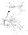
도 1은 본 발명에 따른 전기 자동차 충전장치의 커넥터의 하나의 실시예와 상기 커넥터가 착탈가능하게 장착되는 전기 자동차의 인렛의 분리된 상태를 도시한다.
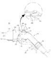
도 2는 본 발명에 따른 전기 자동차 충전장치 커넥터의 하나의 실시예의 측면 방향 투시도를 도시한다.
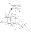
도 3은 본 발명에 따른 전기 자동차 충전장치 커넥터의 다른 실시예의 측면 방향 투시도를 도시한다.
도 4는 본 발명에 따른 전기 자동차 충전장치의 커넥터의 분해 사시도를 도시한다.
도 5는 본 발명에 따른 전기 자동차 충전장치의 커넥터의 단면도를 도시한다.
도 6은 도 2에 도시된 본 발명에 따른 전기 자동차 충전장치의 커넥터의 레버를 당긴 상태에서의 투시도를 도시한다.
도 7는 도 3에 도시된 본 발명에 따른 전기 자동차 충전장치의 커넥터의 레버를 당긴 상태에서의 투시도를 도시한다.Fig. 1 shows one embodiment of a connector of an electric vehicle charging apparatus according to the present invention and an isolated state of an inlet of an electric vehicle to which the connector is detachably mounted.
Figure 2 shows a side view in perspective of one embodiment of an electric vehicle charging device connector according to the present invention.
Figure 3 shows a side view in perspective of another embodiment of an electric vehicle charging device connector according to the present invention.
4 shows an exploded perspective view of a connector of an electric vehicle charging apparatus according to the present invention.
Fig. 5 shows a sectional view of a connector of an electric vehicle charging apparatus according to the present invention.
Fig. 6 shows a perspective view of the connector of the electric vehicle charging apparatus according to the present invention shown in Fig. 2 in a state where the lever is pulled.
Fig. 7 shows a perspective view of the connector of the electric vehicle charging apparatus according to the present invention shown in Fig. 3 when the lever is pulled. Fig.
이하, 첨부된 도면들을 참조하여 본 발명의 바람직한 실시예들을 상세히 설명하기로 한다. 그러나, 본 발명은 여기서 설명된 실시예들에 한정되지 않고 다른 형태로 구체화될 수도 있다. 오히려, 여기서 소개되는 실시예들은 개시된 내용이 철저하고 완전해질 수 있도록, 그리고 당업자에게 본 발명의 사상이 충분히 전달될 수 있도록 하기 위해 제공되는 것이다. 명세서 전체에 걸쳐서 동일한 참조번호들은 동일한 구성요소들을 나타낸다.Hereinafter, preferred embodiments of the present invention will be described in detail with reference to the accompanying drawings. However, the present invention is not limited to the embodiments described herein but may be embodied in other forms. Rather, the embodiments disclosed herein are provided so that the disclosure can be thorough and complete, and will fully convey the scope of the invention to those skilled in the art. Like reference numerals designate like elements throughout the specification.
도 1은 본 발명에 따른 전기 자동차 충전장치의 커넥터(100)의 하나의 실시예와 상기 커넥터(100)가 착탈 가능하게 장착되는 전기 자동차의 인렛(200)의 분리된 상태를 도시한다.1 shows an embodiment of a
상기 인렛(200)은 인렛 하우징(210) 내에 암형 전력 터미널(220) 및 통신 터미널(230)이 구비되고, 개폐가능한 커버(240)에 의하여 차폐될 수 있다.The
본 발명에 따른 전기 자동차 충전장치의 커넥터(100)는 커낵터 본체(110) 내부에 터미널 하우징(130)이 구비되고, 상기 터미널 하우징(130) 내부에 각각 수형 전력 터미널(132) 및 통신 터미널(133)이 구비될 수 있다.The
따라서, 전기차의 충전시 사용자는 전기 자동차 충전장치의 커넥터(100)를 상기 인렛(200)에 장착하고 터미널 간의 접속이 완료되면, 전기 자동차 충전장치는 상기 커넥터를 경유하여 전기 자동차의 베터리(미도시)로 전력을 공급하여 베터리를 충전할 수 있다.Accordingly, when the electric vehicle is charged, the user mounts the
상기 커넥터(100)의 전력 터미널(132) 및 통신 터미널(133)이 장착된 터미널 하우징(130)은 충전상태에서는 상기 인렛(200)을 구성하는 인렛 하우징(210) 내부에 삽입되어 장착되어야 하지만 비충전상태에서는 안전 또는 규격등을 이유로 외부로 노출되지 않을 수 있다.The
즉, 상기 커넥터(100)의 전력 터미널 및 통신 터미널(133)이 장착된 터미널 하우징(130)은 충전을 위한 장착상태에서만 외부로 노출되거나 개방구 측으로 변위되도록 할 수 있다.That is, the power terminal of the
따라서, 이와 같은 선택적 노출, 돌출 또는 변위되는 구조를 위하여, 상기 커넥터(100)는 커넥터 본체(110)을 구비하고 커넥터 본체(110) 내부에 터미널 하우징(130)이 슬라이딩 변위 가능하도록 장착되는 구조를 갖을 수 있다.The
또한, 상기 커넥터(100)의 전력 터미널(132) 및 통신 터미널(133)이 장착된 터미널 하우징(130)은 충전상태, 즉 상기 인렛 하우징(210)에 장착되는 과정은 일정한 크기 이상의 힘이 요구되며, 장착과정에서 요구되는 사용자의 실제 힘을 감소시키기 위하여 레버(150)를 사용할 수 있다. 즉, 레버(150)를 사용하여 힘의 이득을 확보하여, 실제 사용자는 적은 힘으로 쉽게 상기 커넥터(100)를 상기 인렛(200)에 장착할 수 있게 될 수 있다. 특히, 노약자 또는 여성 운전자의 경우, 레버를 사용하지 않는다면 커넥터의 장착과정에서 물리적인 부담을 느낄 수 있다.The
또한, 사용자가 쉽게 커넥터(100)를 한손으로 홀딩할 수 있도록 절곡된 형상을 갖는 핸들(140)를 구비할 수 있다. 상기 핸들(140) 내부로 전술한 복수의 터미널에 접속되는 케이블(C)이 통과될 수 있다.Further, the
도 2 이하를 참조하여, 본 발명에 따른 전기 자동차 충전장치의 커넥터의 구조 등을 자세하게 검토하기로 한다.The structure and the like of the connector of the electric vehicle charging apparatus according to the present invention will be examined in detail with reference to FIG. 2 and the following figures.
도 2는 본 발명에 따른 전기 자동차 충전장치 커넥터의 하나의 실시예의 측면 방향 투시도를 도시하며, 도 3은 본 발명에 따른 전기 자동차 충전장치 커넥터의 다른 실시예의 측면 방향 투시도를 도시한다.Figure 2 shows a lateral side perspective view of one embodiment of an electric vehicle charging device connector according to the present invention and Figure 3 shows a side view in side view of another embodiment of an electric vehicle charging device connector according to the present invention.
먼저, 도 2를 참조하여, 본 발명에 따른 전기 자동차 충전장치의 커넥터에 대하여 설명한다.First, a connector of an electric vehicle charging apparatus according to the present invention will be described with reference to FIG.
본 발명에 따른 전기차 충전장치의 커넥터는 통신 터미널 및 전력 터미널(미도시), 상기 통신 터미널 및 상기 전력 터미널 장착된 터미널 하우징(130), 양단에 개방구를 구비하며, 상기 터미널 하우징이 내부 공간에서 변위 가능하도록 장착되는 커넥터 본체(110), 상기 커넥터 본체(110)에 힌지에 의해 결합되고, 상기 터미널 하우징의 전단부가 상기 개방구 중 어느 하나의 개방구(111, 도 4 참조) 방향으로 변위되도록 상기 터미널 하우징(130)을 추진하는 레버(150)를 포함한다.The connector of the electric vehicle charging apparatus according to the present invention has a communication terminal and a power terminal (not shown), the communication terminal and the terminal housing with the power terminal, and openings at both ends, A
도 2에 도시된 바와 같이, 각각의 터미널이 장착된 터미널 하우징(130)이 상기 커넥터 본체(110) 내측 공간 중 전방에 배치되며, 핸들(140)이 상기 터미널 하우징(130)의 후단부(130b)에 연결된다.2, a
상기 핸들(140)은 상기 터미널 하우징(130)의 후단부에 체결되며, 상기 레버의 회전시 상기 터미널 하우징(130)에 의하여 견인되고, 상기 커넥터 본체(110)의 다른 하나의 개방구(113, 도 4 참조)에서 슬라이딩 가능하다.The
구체적으로, 상기 핸들(140)은 손잡이부(141) 및 상기 손잡이부(141)에서 연장 및 절곡되며 상기 터미널 하우징의 후단부(130b)에 고정 체결되어 상기 커넥터 본체의 다른 하나의 개방구(113, 도 4 참조)에서 슬라이딩 가능한 슬라이딩부(142)를 포함할 수 있다.Specifically, the
따라서, 상기 터미널 하우징(130)과 상기 핸들(140)은 상기 커넥터 본체(110) 내부에서 체결되며, 상기 터미널 하우징(130)이 상기 커넥터 본체(110) 내부에서 변위되는 경우, 상기 핸들(140) 역시 상기 커넥터 본체(110) 내에서 변위될 수 있다.Accordingly, the
그리고, 상기 터미널 하우징(130)은 후술하는 레버(150)에 의하여 미리 결정된 방향, 예를 들면 수평방향 중 좌측방향(도 2참조)으로 추진될 수 있다. 상기 터미널 하우징(130)을 추진하는 이유는 본 발명에 따른 커넥터(100)를 상기 인렛(200)에 장착하는 과정에서 상기 터미널 하우징(130)을 전방으로 변위시키기 위함이다. 즉, 상기 터미널 하우징(130)은 레버에 의하여 추진되는 추진부재로 작용하게 된다.The
본 발명에 따른 전기 자동차 충전장치의 커넥터는 레버 등에 의하여 터미널이 수용된 하우징이 직접 추진되는 구조를 갖으므로, 별도의 추진부재를 사용하지 않으므로 구동부품의 개수를 최소화할 수 있다.The connector of the electric vehicle charging apparatus according to the present invention has a structure in which a housing accommodating a terminal is directly pushed by a lever or the like, so that the number of driving parts can be minimized since no separate propelling member is used.
상기 핸들(140)은 상기 터미널 하우징(130)의 후단부(130b)에 체결되며, 상기 터미널 하우징(130)에 의하여 견인될 수 있으며, 상기 커넥터 본체(110)의 다른 하나의 개방구(113, 도 4 참조)에서 슬라이딩 가능할 수 있다.The
구체적으로 상기 핸들(140)은 손잡이부(141) 및 상기 손잡이부(141)에서 연장 및 절곡되며 상기 터미널 하우징(130)의 후단부(120a)에 체결되어 상기 커넥터 본체(110)의 다른 하나의 개방구로 슬라이딩 가능한 슬라이딩부(142)를 포함할 수 있다.The
도 2에 도시된 바와 같이, 상기 핸들(140)의 슬라이딩부(142)는 상기 커넥터 본체(110)의 후단 영역 내부에서 상기 터미널 하우징(130)의 후단부(130b)에 체결 고정되고, 상기 슬라이딩부(142)와 일체로 형성된 상기 손잡이부(141)은 상기 복수의 터미널(131)에 접속되는 케이블(C)이 통과되는 파이프 형상으로 구성될 수 있다.2, the sliding
구체적으로, 도 2에 도시된 바와 같이, 상기 핸들(140)의 슬라이딩부(142)가 상기 터미널 하우징(130)의 후단부(130b)에 고정되어 커넥터 본체(110)의 후반부에 슬라이딩 가능하게 설치되고, 그 뒷부분으로 케이블(C)이 통과되는 내부 경로가 구비되고 사용자의 손으로 잡을 수 있는 손잡이 형태의 손잡이부(141)를 가지며, 후반부에 상기 내부 경로의 내경에 대응하는 크기를 갖는 케이블 보호부재(145)가 끼워 결합되는 형태로 구성될 수 있다.2, the sliding
상기 손잡이부(141)와 상기 슬라이딩부(142)는 사용자가 손으로 잡기 편한 각도가 되도록 절곡될 수 있다.The
상기 핸들(140)의 상기 슬라이딩부(142)는 상기 커넥터 본체(110)의 길이방향 또는 상기 터미널 하우징의 변위방향과 평행한 부분이다. 손잡이부와 슬라이딩부가 명확하게 구분되지 않고 완만한 곡선 등으로 형성하는 경우보다, 수평한 슬라이딩부와 그 단부에서 절곡된 손잡이부 구획하여 구성하는 방법으로, 상기 레버(150)를 당기는 등의 동작시 부드럽게 슬라이딩 동작이 가능하고, 내구성 역시 향상될 수 있다.The sliding
상기 케이블 보호부재(145)는 고무 재질로 이루어져 커넥터(100)에 도입되는 케이블(C)을 보호한다. 또한, 케이블 보호부재(145)의 크기가 핸들(140)의 내경에 대응하는 크기로 형성됨으로써, 다양한 사이즈의 케이블을 커넥터(100)에 적용하여 사용하는 것이 가능하며, 기밀을 보장하여 침수 등의 안전사고 등을 예방할 수 있다.The
상기 터미널 하우징(130)은 상기 레버(150)의 회전시 상기 레버(150)에 의하여 추진되기 위하여 레버(150)의 회전 모멘트를 미리 결정된 방향의 추진력으로 변환하기 위한 추진력 변환수단이 필요하다.The
따라서, 본 발명에 따른 전기 자동차 충전장치의 커넥터는 추진력 변환수단으로서 상기 터미널 하우징의 측면에 가이드핀 및 상기 레버의 상단부에 상기 레버의 회전에 따른 가이드핀의 회전 궤적에 따라 상기 터미널 하우징을 추진하기 위한 가이드홀을 구비한다.Therefore, the connector of the electric vehicle charging apparatus according to the present invention is characterized in that it comprises a guide pin on a side surface of the terminal housing as a thrust converting means, and a terminal pin on the upper end of the lever in accordance with the rotation locus of the guide pin, A guide hole is provided.
도 2에 도시된 실시예에서, 상기 레버(150)의 상단부(159)에 장공 형태의 가이드홀(1502)이 구비되고, 상기 터미널 하우징(130)에는 상기 레버(150)의 회전에 따라 상기 레버(150)의 상단부(159)의 가이드홀(1502)에 삽입되어 터미널 하우징(130)을 추진하기 위한 가이드핀(136)이 구비된다.2, a
상기 가이드핀(136)은 상기 가이드홀(1502)의 회전 궤적에 따라 레버의 회전력을 수평방향 추진력으로 변환하게 된다. 따라서, 상기 가이드홀(1502)는 장공 형태로 구성될 수 있다.The
상기 가이드홀(1502)은 상기 레버(150)의 상단부(159)의 길이방향과 평행하게 형성될 수 있다.The
그리고, 상기 가이드핀(136)은 상기 터미널 하우징의 양측면 상에 서로 대응되는 위치에 한 쌍이 구비될 수 있다. 또한, 상기 레버(150)의 상단부(159)는 상기 힌지(151) 근방에서 분지되어 각각의 가이드핀 방향으로 절곡 및 연장될 수 있다.The pair of guide pins 136 may be provided at positions corresponding to each other on both sides of the terminal housing. The
상기 레버(150)에 의하여 추진되는 매개체가 터미널 하우징(130) 등에 구비된 가이드핀(136)이므로, 가이드핀(136)과 레버의 힌지 사이의 거리를 증가시켜 레버의 회전시 인가되는 회전 모멘트를 극대화하여 커넥터의 장착과정에서의 요구되는 사용자의 힘의 크기를 최소화할 수 있다는 장점이 있다.Since the medium propelled by the
그리고, 전술한 바와 같이, 상기 레버(150)는 커넥터 본체(110)에 힌지(151)에 의하여 힌지결합될 수 있다. 상기 힌지(151)에 상기 레버(150)의 회전시 복원력을 제공하는 스프링(158, 도 4 참조)이 구비될 수 있다.As described above, the
따라서, 사용자가 핸들(140)의 하부 영역인 손잡이부(141)를 잡고 상기 레버(150)를 상기 핸들(140) 측으로 견인하면, 상기 가이드핀(136)은 상기 가이드홀(1502) 내측 벽면을 따라 가압되며, 수평방향으로 추진되어 상기 터미널 하우징(130)를 일측으로 변위시킬 수 있다.When the user grips the
이와 같은 구조에 의하여, 상기 터미얼 하우징(130) 및 상기 핸들(140)은 체결 및 고정된 상태에서 상기 터미얼 하우징(130)이 변위됨에 따라 함께 슬라이드 변위될 수 있다.With such a structure, the
그리고, 상기 가이드핀과 상기 가이드홀은 그 장착위치가 서로 바뀌어 상기 레버의 상단부에 가이드핀이 구비되고, 상기 터미널 하우징(130)의 측면에 상기 레버의 가이드핀이 삽입되는 가이드홀이 구비되도록 구성할 수도 있다.The guide pins and the guide holes are arranged so that the guide pins are formed at the upper ends of the levers, and guide holes for inserting the guide pins of the levers are formed on the side surfaces of the
전술한 터미널 하우징(130)의 추진 구조는 전기 자동차의 충전을 위하여 커넥터를 전기 자동차의 인렛에 장착하 커넥터의 장착과정을 위한 것이며, 이하 커넥터의 장착과정이 완료된 뒤, 장착상태를 유지한 상태로 충전과정이 수행되기 위하여 장착상태를 유지하기 위한 구조에 대하여 도 2 및 도 3을 참조하여 설명한다.The above-described propulsion structure of the
본 발명에 따른 전기 자동차 충전장치의 커넥터(100)는 상기 커넥터 본체(110)에서 상기 터미널 하우징(130)이 변위된 상태를 고정하기 위하여 추진된 터미널 하우징(130) 또는 핸들(140)에 걸림 고정되는 고정레치를 더 포함할 수 있다. 즉, 고정레치는 변위된 터미널 하우징 또는 핸들이 변위된 상태로 유지되도록 구속하는 역할을 수행한다.The
구체적으로, 도 2에 도시된 실시예에서, 상기 고정레치(161)는 변위된 핸들(140)의 변위 상태를 고정하며, 도 3에 도시된 실시예서, 상기 고정레치(161)는 변위된 터미널 하우징(130)을 고정하는 구성이다.2, the fixed latch 161 fixes the displacement state of the displaced
따라서, 도 2 및 도 3에 도시된 실시예에서, 각각의 고정레치(161)는 고정레치와 걸림 고정되는 걸림돌기의 위치에 따라 터미널 하우징(130) 또는 핸들(140)를 고정하게 된다.Thus, in the embodiment shown in FIGS. 2 and 3, each of the fixed latches 161 fixes the
도 2에 도시된 실시예에서, 상기 걸림돌기(1402)는 상기 핸들(140)의 상단면에 구비되며, 도 3에 도시된 실시예는 상기 걸림돌기(1302)는 터미널 하우징(130)의 후단부(130b) 상단면에 구비된다.In the embodiment shown in FIG. 2, the locking
각각의 걸림돌기(1302, 1402)는 상기 레버(150)의 회전에 따라 상기 터미널 하우징(130)이 추진된 상태에서, 상기 핸들(140) 또는 상기 레버(150)의 변위된 상태를 유지하도록 고정하기 위하여 구비된다.Each of the locking
그리고, 각각의 걸림돌기(1302, 1402)는 단면방향 경사가 서로 다를 수 있다. 경사가 다른 이유는 후술한다.Each of the engaging
그리고, 도 3에 도시된 실시예는 도 2에 도시된 실시예와 달리, 전기 자동차의 인렛에 커넥터가 체결된 상태를 유지하기 위한 체결레치(111)를 더 포함할 수 있다.In addition, the embodiment shown in FIG. 3 may further include a locking
도 2 또는 3에 도시된 실시예에서, 상기 고정레치(161)는 상기 터미널 하우징이 상기 레버에 의하여 추진된 상태를 고정하기 위한 구성이다. 즉, 전기 자동차의 충전과정에서 터미널 하우징의 돌출 또는 변위된 상태를 유지하기 위한 구성이다.In the embodiment shown in FIG. 2 or 3, the fixed latch 161 is a structure for fixing the state in which the terminal housing is propelled by the lever. That is, it is a structure for maintaining the protruded or displaced state of the terminal housing in the charging process of the electric vehicle.
그리고, 도 3에 도시된 상태에서, 상기 체결레치(111)는 상기 커넥터 본체(130)가 상기 인렛(200)에 장착된 상태에서 의도하지 않게 분리되는 것을 차단하기 위한 구성이다.In the state shown in FIG. 3, the locking
즉, 상기 체결레치(111)는 상기 고정레치에 의하여 터미널 하우징이 추진된 상태가 유지되는 상황에서 상기 커넥터가 전기 자동차의 인렛으로부터 분리되는 것을 차단하기 위한 구성이다.That is, the locking
도 3에 도시된 바와 같이, 상기 고정레치(161)와 상기 체결레치(111)는 상기 커넥터 본체의 내측 상단면 중심부에 각각 힌지결합될 수 있다.As shown in FIG. 3, the fixing latch 161 and the locking
상기 고정레치(161)는 일단(161a)은 후술하는 해제버튼(162)에 의하여 선택적으로 가압되는 구성이며, 상기 고정레치(161)의 타단(161b)은 후술하는 터미널 하우징의 걸림돌기(1302)에 걸림되는 고정돌기(161c)가 구비될 수 있다.One
상기 체결레치의 일단(111a)은 상기 고정레치의 타단(161b)의 타단 상부에 배치되며, 상기 체결레치의 타단(111b)에는 체결돌기(111c)가 형성되며 상기 체결돌기(111c)상기 커넥터 본체 외부로 돌출될 수 있다.The
상기 체결레치(111)의 일단(111a)은 상기 고정레치의 타단(161b)의 타단 상부에 배치되는 이유는 고정상태의 해제동작이 체결상태를 동시에 해제되도록 하기 위함이다. 즉, 고정레치의 해제과정에서 고정레치의 타단(161b)가 체결레치의 일단(111a)의 하부를 가압하여 회전시킴으로써, 상기 체결돌기(111c)가 형성된 체결레치의 타단을 하강시켜 체결돌기에 의한 전기 자동차 인렛에의 체결상태를 해제할 수 있다.One
도 2 및 도 3에 도시된 실시예에서, 상기 고정돌기(161c) 및 상기 체결돌기(111c)는 각각 고정레치(161) 및 체결레치(111)의 단부에서 돌출되어 구성되고 각각의 상기 고정돌기(161c) 및 상기 체결돌기(111c)는 커넥터의 장착과정에서는 물리적인 저항을 최소화하고 커넥터의 체결상태 및 터미널 하우징의 고정상태를 유지하기 위하여 각각 서로 다른 단면 경사를 갖을 수 있다.2 and 3, the fixing
전술한 바와 같이, 상기 터미널 하우징(130) 및 상기 핸들(140)는 상기 고정돌기(161c)에 의하여 선택적으로 걸림되도록 걸림돌기(1302, 1402)가 구비될 수 있다.As described above, the
상기 걸림돌기(1302, 1402)는 상기 터미널 하우징의 상단면 및 상기 핸들의 슬라이딩부 상단면에 형성된 적어도 1개 이상의 돌기일 수 있다. 상기 돌기 중 어느 하나의 돌기의 단면의 측면 경사는 서로 다를 수 있다. 고정레치에 대한 걸림동작이 가능하도록 하기 위함이다.The locking
상기 걸림돌기가 복수 개가 구비되고, 그 사이에 안착공간을 형성하는 방법 역시 가능하지만, 설명의 편의를 위하여 한 개만 구비되는 경우를 설명한다.A plurality of the locking protrusions may be provided and a seating space may be formed therebetween. However, for convenience of explanation, only one locking protrusion is provided.
상기 걸림돌기(1302, 1402)의 일측면(도 2 및 도 3의 도면부호 1302, 1402의 우측면) 및 상기 걸림돌기(161c) 일측면(도 2 및 도 3의 도면부호의 161c의 좌측면)은 각각 수직한 경사를 갖을 수 있다.(The left side of 161c in FIG. 2 and FIG. 3) of one side (the right side of
고정레치에 의한 고정상태가 쉽게 해제되는 것을 차단하기 위함이다. 즉, 상기 고정돌기(161c)가 상기 걸림돌기(1302, 1402)를 타고 넘어간 경우, 상기 레버(150)에 장착된 스프링 등의 복원력에 의하여 상기 터미널 하우징(130)이 후퇴하는 경우, 상기 걸림돌기의 및 고정돌기의 수직한 경사면이 서로 지지되도록 하여 터미널 하우징의 후퇴를 방지할 수 있다.This is to prevent the locked state by the fixed latch from being easily released. That is, when the fixing
상기 걸림돌기(1302, 1402)의 타측면(도 2 및 3의 도면부호 1302, 1402의 좌측면) 및 상기 고정돌기의 일측면(도 2 및 3의 도면부호의 161c의 우측면)은 커넥터의 삽입과정에서 물리적 저항을 최소화하기 위하여 서로 대응되는 방향으로 완만한 경사를 갖을 수 있다. 상기 고정레치 또는 체결레치는 상기 커넥터 본체에 힌지에 의하여 결합되며, 스프링 등의 탄성부재에 의하여 탄성이 부가될 수 있으므로, 대응되는 완만한 경사면을 갖는 고정돌기와 걸림돌기는 커넥터의 장착과정에서는 별도의 저항없이 타고 넘어갈 수 있으므로, 상기 커넥터(100)를 상기 인렛(200)에 장착하는 경우 큰 힘이 소요되지 않고 부드럽게 상기 커넥터(100)를 인렛에 장착할 수 있다.The other side surfaces (the
도 3에 도시된 실시예의 체결레치(111)에 형성된 체결돌기(111c) 역시 단면을 기준으로 양 측면의 경사가 서로 다를 수 있다. 따라서, 즉, 좌측 측면의 경사는 완만하고, 우측 측면의 경사는 수직에 가깝게 가파르게 형성하여, 상기 인렛(200)에 장착하는 경우에는 부드럽게 물리적 저항을 최소화하며 장착될 수 있고, 인렛의 걸림턱(미도시) 등에 우측 측면이 걸림 고정되어 인렛에 장착된 상태가 쉽게 해제되는 것을 방지할 수 있다.The
도 3에 도시된 실시예에서, 상기 커넥터(100)를 장착하고 충전이 완료되면 커넥터의 장착상태를 해제하는 탈착구조가 필요하다.In the embodiment shown in Fig. 3, a detachable structure is required for mounting the
따라서, 도 3에 도시된 본 발명에 따른 실시예는 상기 커넥터 본체에 상기 고정레치(161)(또는 고정돌기(161(c))에 의한 상기 터미널 하우징(130)의 고정상태를 해제하기 위한 해제버튼(162)을 포함하며, 상기 해제버튼(162)에 의해 고정레치의 일단(161a)이 가압되면 고정레치의 타단(161b)에 구비된 고정돌기(161c)가 상승함과 동시에 상기 체켤레치의 일단(111a)을 상승시킴에 따라 상기 체결레치의 타단(111b)를 하강시키고, 타단(111b)에 형성된 체결돌기(111c)는 전기 자동차 인렛으로부터 체결상태를 해제하는 것에 의하여, 상기 고정레치의 해제동작은 상기 체결레치의 체결상태를 해제하게 된다.Therefore, the embodiment according to the present invention shown in Fig. 3 is characterized in that the connector body is provided with a release lever 161 for releasing the fixed state of the
도 2에 도시된 실시예는 체결상태를 유지하는 체결레치를 구비하지는 않으나, 고정레치에 의한 고정상태를 해제하는 방법은 도 3에 도시된 실시예와 마찬가지이다.Although the embodiment shown in FIG. 2 does not have a lock-in state for maintaining the locked state, the method for releasing the locked state by the locked-state latch is the same as the embodiment shown in FIG.
상기 해제버튼(162)을 구비하여 해제버튼을 눌러 고정레치(116)의 고정돌기(116c)가 상기 핸들(140)의 슬라이딩부(142) 상단면에 구비된 걸림돌기(1402)에 걸림 고정된 상태를 선택적으로 해제할 수 있다.The fixing protrusion 116c of the fixed latch 116 is engaged with the locking
그리고, 도 3에 도시된 실시예에서, 해제버튼(162)를 가압하여, 상기 고정레치의 고정돌기(161c)와 상기 터미널 하우징의 걸림돌기(1302)의 고정상태를 해제함과 동시에, 상기 체결레치의 타단(111b)이 하강되어 전기 자동차 인렛에 대한 상기 체결레치의 체결상태를 해제하도록 구성될 수 있다.3, the
즉, 상기 고정레치의 고정상태 해제 동작은 상기 체결레치의 체결상태를 연동하여 해제하는 특징을 갖게 될 수 있다. 그리고, 도 3에 도시된 실시예에서, 상기 체결레치(111)의 대칭되는 부분에 체결상태의 잠금해제와 무관한 더미레치(112)가 구비될 수 있다.That is, the fixed state releasing operation of the fixed latch may be characterized by releasing the locking state of the locking latch in cooperation with each other. In the embodiment shown in FIG. 3, a symmetrical portion of the locking
상기 더미레치(112)는 조건에 따라 커넥터의 체결상태를 유지 또는 해제하는 것이 아니라 커넥터의 장착과정 또는 착탈과정에서 상기 체결레치(111)와 보조를 맞추기 위하여 구비되며, 상기 체결레치와 달리 돌기의 경사가 모두 완만하게 구성될 수 있으며, 상기 체결레치(111)와 마찬가지로 상기 커넥터 본체(110)에 힌지결합될 수 있다. 상기 더미레치의 경우, 두께를 얇게 구성하여 어느 정도의 탄성력을 제공하도록 구성될 수도 있다. 따라서, 상기 더미레치(112)는 커넥터를 인렛에 장착하는 장착과정을 부드럽게 안내하고 어느 정도의 지지력을 제공할 수 있다.The
결론적으로, 본 발명에 따른 전기 자동차 충전장치의 커넥터에 의하면, 전기 자동차 충전장치의 커넥터와 전기 자동차의 인렛에의 장착과정은 인렛에 커넥터를 거치한 상태로 레버의 견인에 의하여 수행될 수 있으며, 탈착과정은 해제버튼을 누르고 커넥터를 인렛으로부터 분리할 수 있으므로, 장착과정 및 탈착과정이 간편해질 수 있다.As a result, according to the connector of the electric vehicle charging apparatus according to the present invention, the connector of the electric vehicle charging apparatus and the process of mounting the connector to the inlet of the electric vehicle can be performed by pulling the lever with the connector mounted on the inlet, The dismounting process can be performed by pressing the release button and separating the connector from the inlet, so that the mounting process and the dismounting process can be simplified.
또한, 체결레치 등을 사용하여 전기 자동차의 충전과정에서 인렛에서 커넥터가 의도하지 않게 분리되는 것을 방지할 수 있으므로 전기 자동차 충전장치의 커넥터의 신뢰성도 향상시킬 수 있다.In addition, since the connector can be prevented from being unintentionally disconnected from the inlet during the charging process of the electric vehicle by using the fastening latch or the like, the reliability of the connector of the electric vehicle charging apparatus can be improved.
도 2 및 도 3에 도시된 실시에에서, 상기 해제버튼(162)은 상기 커넥터 본체(130)의 다른 하나의 개방구 근방의 상부 중심영역에 구비될 수 있다.In the embodiment shown in FIGS. 2 and 3, the
사용자가 왼손잡이 또는 오른손잡이인지와 무관하고, 핸들을 잡은 한손으로도 착탈과정을 수행할 수 있도록 상기 해제버튼(162)은 상기 커넥터 본체(110)의 상부 영역의 후방 중심부에 구비될 수 있다.The
그리고, 상기 해제버튼은 광투과성 재질로 구성되고, 그 내부에 적어도 1가지 이상의 발광 색상을 갖는 광원(163)를 구비할 수 있다.The release button may be made of a light-transmitting material, and may include a
단일 색상의 광원인 경우에는 광원(163)의 온-오프 또는 일정한 방법에 의한 점멸에 의하여 충전상태, 완료상태 또는 에러상태 등을 구별하여 표시할 수 있다. 예를 들면 충전상태, 완료상태 및 에러상태에서 각각 지속 점등, 지속 소등 및 일정 간격 점멸 등의 방법이 사용될 수 있다.In the case of a single color light source, the charging state, the completion state, or the error state can be distinguished and displayed by on / off of the
그리고, 광원의 색상이 2가지 이상인 경우에는 상기 광원(163)은 적어도 2개 이상의 다른 발광색상을 갖는 LED 소자를 포함할 수 있다.If the light source has two or more colors, the
서로 다른 색상을 갖는 LED 소자를 사용하여, 전기 자동차 충전장치의 제어부는 전기 자동차 충전상태에 따라 상기 LED 소자의 발광 색상을 다르게 제어할 수 있다. 예를 들면, 충전중에는 적색 LED 소자를 점등시키고, 충전 완료되면 녹색 LED 소자를 점등하여 사용자로 하여금 충전상태를 쉽게 판단할 수 있도록 하기 위함이다.Using the LED device having different colors, the control unit of the electric vehicle charging apparatus can control the emission color of the LED device differently according to the charged state of the electric vehicle. For example, the red LED device is turned on during charging, and the green LED device is turned on when charging is completed, so that the user can easily determine the charging state.
도 4는 본 발명에 따른 도 3에 도시된 전기 자동차 충전용 커넥터의 분해 사시도를 도시한다. 도 4에 도시된 바와 같이, 상기 터미널 하우징(130)은 원통 형상의 구조물로서 상기 전력 터미널(131) 및 통신 터미널(132)이 삽입 장착되도록 형성된 전력 터미널 장착구(137)와 통신 터미널 장착구(139)가 구비될 수 있다.Fig. 4 shows an exploded perspective view of the connector for charging an electric vehicle shown in Fig. 3 according to the present invention. 4, the
상기 통신 터미널 장착구(139)는 복수 개가 하나의 장착구를 구성할 수 있다. 상기 터미널(131, 132)의 뒷부분에서 실링 기능을 제공하는 실링부재(133)와, 상기 실링부재(133)가 상기 터미널(131)의 선단 방향으로 이동하는 것을 차단하도록 실링부재(133)의 앞부분에 구비되고, 실링부재(133)의 내경에 비해 큰 외경을 갖는 지지부재(134)와, 상기 실링부재(133)의 수단에 밀착되도록 체결되고, 상기 터미널(131)에 대응하는 케이블(C)로부터 분기된 양극 또는 음극 도선(W)의 인입을 위한 케이블 도입구가 형성된 리어홀더(135)를 포함할 수 있다.The plurality of communication terminal fittings 139 can constitute one mounting hole. A sealing
도 3에 도시된 실시예에서, 상기 실링부재, 지지부재 및 리어홀더는 상기 전력 터미널에만 구비되는 것으로 도시되었으나, 당연히 통신 터미널의 실링을 위하여 추가될 수 있다.In the embodiment shown in Fig. 3, the sealing member, the supporting member and the rear holder are shown as being provided only to the power terminal, but may of course be added for sealing of the communication terminal.
이와 같은 구성은, 커넥터(100)와 인렛(200)의 체결 과정에서 과도한 힘이 작용되더라도 터미널(131)의 후미에 위치한 실링부재(133)와 지지부재(134)에 의해 안정적으로 지지될 수 있어 정위치가 보유될 수 있으며, 실링부재(133)에 의해 케이블 접합부의 실링 상태가 안정적으로 유지될 수 있도록 한다.This configuration can be stably supported by the sealing
도 4에 도시된 바와 같이, 상기 터미널 하우징(130)의 상단면에 고정레치에 의하여 걸림 고정되는 걸림돌기(1302)가 형성될 수 있다.As shown in FIG. 4, a
도 5는 본 발명에 따른 전기 자동차 충전장치의 커넥터의 단면도를 도시한다. 도 5에 도시된 바와 같이, 상기 커넥터 본체의 측면에는 가이드 돌기(136)가 한쌍이 구비되고 상기 레버의 상단부에 형성된 장공형 가이드홀(1502)에 삽입되어 장착된다.Fig. 5 shows a sectional view of a connector of an electric vehicle charging apparatus according to the present invention. 5, a pair of
상기 레버(150)의 상단부는 힌지(151) 근방에서 분기되어 상기 터미널 하우징(130)의 측면 방향으로 연장된다. 따라서, 연장된 한 쌍의 레버의 상단부는 각각의 가이드핀(136)을 가이드홀 내부에 안착시킨 상태로 레버의 회전방향에 대응되는 방향으로 상기 터미널 하우징을 추진하게 된다.The upper end of the
그리고, 전술한 바와 같이 가이드핀과 가이드홀의 위치는 서로 바뀔 수 있으므로 가이드핀을 상기 레버의 상단부에 구비하고 상기 터미널 하우징에 가이드홀을 구비할 수 도 있다.As described above, since the positions of the guide pin and the guide hole may be reversed, a guide pin may be provided at an upper end of the lever, and a guide hole may be provided in the terminal housing.
도 6은 도 2에 도시된 전기 자동차 충전장치의 커넥터의 레버를 당긴 상태에서 상기 터미널 하우징이 추진된 상태를 도시하며, 도 7은 도 3에 도시된 전기 자동차 충전장치의 커넥터의 레버를 당긴 상태에서 상기 터미널 하우징이 추진된 상태를 도시한다.Fig. 6 shows a state in which the terminal housing is pushed in a state in which the lever of the connector of the electric vehicle charging apparatus shown in Fig. 2 is pulled, Fig. 7 shows a state in which the lever of the connector of the electric vehicle charging apparatus shown in Fig. In which the terminal housing is propelled.
도 2 및 도 3에 도시된 실시예에서, 사용자가 커넥터(100)에 구비된 레버(150)의 레버부(153)를 상기 핸들(140)의 손잡이부(141) 측으로 당기는 경우, 상기 레버의 상단부에 형성된 가이드홀(1402)에 의하여 상기 터미널 하우징(130)에 구비된 가이드핀(136)이 상기 레버의 회전방향에 대응하여 추진된다.2 and 3, when the user pulls the
즉, 상기 힌지(141)에 의하여 회전 가능하게 지지되는 레버(150)가 회전하면, 상기 터미널 하우징(130)이 전기 자동차 인렛 방향으로 추진되어 전기 자동차 인렛에 접속될 수 있다.That is, when the
그리고, 각각의 실시예에서 고정레치(161)의 고정돌기(161c)은 핸들의 슬라이딩부(142) 또는 터미널 하우징(130)의 상단면에 구비된 걸림돌기(1302, 1402)에 걸림된다.In each of the embodiments, the fixing
전술한 바와 같이 고정돌기와 걸림돌기의 경사방향은 부드러운 장착이 가능하도록 대응되는 경사를 갖으므로, 터미널 하우징(130)을 변위시키는 것에 큰 힘이 소요되지 않는다.As described above, since the fixing protrusions and the inclining direction of the locking protrusions have corresponding inclination to allow smooth mounting, a great force is not required to displace the
또한, 상기 고정돌기의 경사면이 상기 걸림돌기의 경사면을 타고 넘어가면, 레버에 스프링이 설치되어 복원력이 작용하여도 각각 고정레치의 고정돌기와 걸림돌기의 수직한 측면이 서로 걸림되어 터미널 하우징의 추진 또는 변위된 상태가 유지될 수 있다.In addition, when the inclined surface of the fixing protrusion rides over the inclined surface of the locking protrusion, even if a spring is provided on the lever and a restoring force is applied, the vertical protrusion of the locking protrusion and the vertical side surface of the locking protrusion are engaged with each other, The displaced state can be maintained.
그리고, 도 6 및 도 7에 도시된 커넥터는 각각 해제버튼(162)을 구비하여 충전이 완료된 후 터미널 하우징(130) 또는 핸들(140)의 고정상태를 해제하여 레버(150)에 인가되는 탄성에 의한 복원력에 의하여 터미널 하우징(130)이 후퇴하도록 구성할 수 있다.6 and 7 are respectively provided with a
즉, 도 4에 도시된 바와 같이, 상기 레버(150)은 상기 커넥터 본체(130)에 스프링(158)에 의하여 지지되므로, 레버의 견인상태가 해제되면 복원력이 상기 레버를 원래의 위치로 회전시킬 수 있다.4, since the
이 경우, 상기 해제버튼(162)에 의하여 상기 고정레치(161)의 걸림돌기(1302, 1402)의 걸림상태가 해제되고 상기 레버(150)에 인가되는 복원력은 상기 핸들(140)의 슬라이딩부(142)가 고정된 상기 터미널 하우징(130)을 후퇴시켜, 터미널 하우징(130)이 상기 커넥터 본체(110) 내측 공간으로 수용되도록 한다.In this case, the latching
본 명세서는 본 발명의 바람직한 실시예를 참조하여 설명하였지만, 해당 기술분야의 당업자는 이하에서 서술하는 특허청구범위에 기재된 본 발명의 사상 및 영역으로부터 벗어나지 않는 범위 내에서 본 발명을 다양하게 수정 및 변경 실시할 수 있을 것이다. 그러므로 변형된 실시가 기본적으로 본 발명의 특허청구범위의 구성요소를 포함한다면 모두 본 발명의 기술적 범주에 포함된다고 보아야 한다.While the present invention has been particularly shown and described with reference to preferred embodiments thereof, it will be understood by those skilled in the art that various changes and modifications may be made without departing from the spirit and scope of the invention as defined in the following claims. . It is therefore to be understood that the modified embodiments are included in the technical scope of the present invention if they basically include elements of the claims of the present invention.
100 : 커넥터 200 : 인렛
110 : 커넥터 본체 120 : 터미널 하우징
130 : 터미널 하우징 140 : 핸들
150 : 레버100: connector 200: inlet
110: connector body 120: terminal housing
130: terminal housing 140: handle
150: Lever
Claims (17)
Translated fromKorean통신 터미널 및 전력 터미널;
상기 통신 터미널 및 상기 전력 터미널 장착된 터미널 하우징;
양단에 개방구를 구비하며, 상기 터미널 하우징이 내부 공간에서 변위 가능하도록 장착되는 커넥터 본체;
상기 커넥터 본체에 힌지에 의해 결합되고, 상기 터미널 하우징의 전단부가 상기 개방구 중 어느 하나의 개방구 방향으로 변위되도록 상기 터미널 하우징을 추진하는 레버; 및,
상기 터미널 하우징의 후단부에 체결되며, 상기 레버의 회전시 상기 터미널 하우징에 의하여 견인되어, 상기 커넥터 본체의 다른 하나의 개방구에서 슬라이딩 가능한 핸들;을 포함하며,
상기 터미널 하우징의 측면에 가이드핀이 구비되고, 상기 레버의 상단부에 상기 가이드핀이 삽입되는 가이드홀이 구비되며,
상기 레버의 상단부는 상기 힌지에 의한 결합 부위에서 상방향으로 연장되고, 상기 가이드홀은 상기 레버의 상단부의 길이방향으로 장공 형태로 형성되며, 상기 레버의 하단부를 상기 핸들 방향으로 견인하면, 상기 레버의 상단부의 가이드홀 내에 수용된 가이드핀은 상기 전기 자동차의 인렛 방향으로 경사진 상기 가이드홀의 상단으로 변위되며 상기 터미널 하우징을 상기 인렛 방향으로 추진하는 것을 특징으로 하는 전기 자동차 충전장치의 커넥터.A connector of an electric vehicle charging apparatus mounted on an inlet of an electric vehicle,
A communication terminal and a power terminal;
The communication terminal and the power terminal-mounted terminal housing;
A connector body having an opening at both ends thereof, the terminal housing being mounted to be displaceable in an inner space;
A lever coupled to the connector body by a hinge and for pushing the terminal housing such that a front end of the terminal housing is displaced in an opening direction of one of the opening openings; And
And a handle which is fastened to a rear end of the terminal housing and is pulled by the terminal housing when the lever is rotated and is slidable in another opening of the connector body,
A guide pin is provided on a side surface of the terminal housing, and a guide hole for inserting the guide pin is provided at an upper end of the lever,
The upper end of the lever extends upward in the coupling portion by the hinge and the guide hole is formed in the shape of a long hole in the longitudinal direction of the upper end of the lever and when the lower end of the lever is pulled in the handle direction, Wherein the guide pin received in the guide hole at the upper end of the guide hole is displaced to the upper end of the guide hole inclined in the inlet direction of the electric vehicle and pushes the terminal housing toward the inlet.
상기 핸들은 손잡이부 및 상기 손잡이부에서 연장 및 절곡되며 상기 터미널 하우징의 후단부에 체결되어 상기 커넥터 본체의 다른 하나의 개방구에서 슬라이딩 가능한 슬라이딩부를 포함하는 전기 자동차 충전장치의 커넥터.The method according to claim 1,
Wherein the handle includes a handle portion and a sliding portion that is extended and bent at the handle portion and is fastened to a rear end portion of the terminal housing to be slidable in another opening of the connector body.
상기 손잡이부 하부에 손잡이부 내측 직경에 대응되는 직경을 갖는 고무 재질의 케이블 보호부재가 구비되는 것을 특징으로 하는 전기 자동차 충전장치의 커넥터.The method of claim 3,
And a cable protection member made of a rubber material having a diameter corresponding to an inner diameter of the handle portion is provided at a lower portion of the handle portion.
상기 가이드핀은 상기 터미널 하우징의 양측면 상에 서로 대응되는 위치에 한 쌍이 구비되는 것을 특징으로 하는 전기 자동차 충전장치의 커넥터.The method according to claim 1,
And the pair of guide pins are provided at positions corresponding to each other on both side surfaces of the terminal housing.
상기 레버의 상단부는 상기 힌지 근방에서 분지되어 각각의 가이드핀 방향으로 절곡 및 연장되는 것을 특징으로 하는 전기 자동차 충전장치의 커넥터.The method according to claim 6,
And the upper end of the lever is branched at the vicinity of the hinge and bent and extended in the direction of the guide pins.
상기 레버의 회전시 상기 커넥터 본체에서 상기 터미널 하우징이 변위된 상태를 고정하기 위하여 변위된 상기 터미널 하우징에 걸림 고정되는 고정레치 및 전기 자동차의 인렛에 전기 자동차 충전장치의 커넥터가 체결된 상태를 유지하기 위한 체결레치를 더 포함하며, 상기 고정레치의 고정상태 해제 동작은 상기 체결레치의 체결상태를 해제하는 것을 특징으로 하는 전기 자동차 충전장치의 커넥터.The method according to claim 1,
A fixing latch which is engaged with the terminal housing displaced in order to fix a state in which the terminal housing is displaced from the connector body when the lever is rotated; Wherein the fastening releasing operation of the fastening latch releasing the fastening state of the fastening latch.
상기 커넥터 본체에 상기 고정레치에 의한 상기 터미널 하우징의 고정상태를 해제하기 위한 해제버튼을 포함하며, 상기 고정레치 및 상기 체결레치는 상기 커넥터 본체에 힌지결합되고, 상기 해제버튼에 의해 고정레치의 일단이 가압되면 고정레치의 타단이 상기 체결레치의 일단을 상승시킴에 따라 상기 체결레치의 타단이 하강되어 전기 자동차의 인렛에 대한 상기 체결레치의 체결상태를 해제하는 것을 특징으로 하는 전기 자동차 충전장치의 커넥터.9. The method of claim 8,
And a release button for releasing the fixed state of the terminal housing by the fixed latch to the connector body, wherein the fixed latch and the latch latch are hinged to the connector body, The other end of the locking latch is lowered to release the locking state of the locking latch with respect to the inlet of the electric vehicle, as the other end of the locking latch lifts up the one end of the locking latch. connector.
상기 레버의 회전시 상기 커넥터 본체에서 상기 터미널 하우징이 변위된 상태를 고정하기 위하여 상기 핸들에 걸림 고정되는 고정레치를 더 포함하는 것을 특징으로 하는 전기 자동차 충전장치의 커넥터.The method according to claim 1,
Further comprising: a fixing latch fixed to the handle to fix the terminal housing in a state of being displaced from the connector body when the lever is rotated.
상기 커넥터 본체에 상기 고정레치에 의한 상기 터미널 하우징 또는 상기 핸들의 고정상태를 해제하기 위한 해제버튼을 포함하는 것을 특징으로 하는 전기 자동차 충전장치의 커넥터.11. The method of claim 10,
And a release button for releasing the fixed state of the terminal housing or the handle by the fixed latch to the connector body.
상기 해제버튼은 상기 커넥터 본체의 다른 하나의 개방구 근방의 상부 중심영역에 구비되는 것을 특징으로 하는 전기 자동차 충전장치의 커넥터.The method according to claim 9 or 11,
Wherein the release button is provided in an upper central region in the vicinity of the other opening of the connector body.
상기 해제버튼은 광투과성 재질로 구성되고, 그 내부에 적어도 1가지 이상의 발광 색상을 갖는 광원을 구비하는 것을 특징으로 하는 전기 자동차 충전장치의 커넥터.13. The method of claim 12,
Wherein the release button is made of a light-transmitting material, and has a light source having at least one light-emitting color in the light-releasing button.
전기 자동차 충전장치의 제어부는 전기 자동차 충전상태에 따라 상기 광원의 작동방법 또는 발광 색상을 다르게 제어하는 것을 특징으로 하는 전기 자동차 충전장치의 커넥터.14. The method of claim 13,
Wherein the controller of the electric vehicle charging apparatus controls the operation method of the light source or the emission color differently according to the charged state of the electric vehicle.
상기 터미널 하우징 또는 상기 핸들의 상단부에 상기 고정레치가 선택적으로 걸림 고정되는 적어도 1개 이상의 걸림돌기가 형성되는 것을 특징으로 하는 전기 자동차 충전장치의 커넥터.11. The method according to claim 8 or 10,
Wherein at least one locking protrusion is formed at an upper end portion of the terminal housing or the handle so that the locking latch is selectively engaged and locked.
상기 걸림돌기의 측면 경사는 서로 다른 것을 특징으로 하는 전기 자동차 충전장치의 커넥터.16. The method of claim 15,
And the side inclination of the engaging projection is different.
Priority Applications (1)
| Application Number | Priority Date | Filing Date | Title |
|---|---|---|---|
| KR1020110026820AKR101774052B1 (en) | 2011-03-25 | 2011-03-25 | Connector Of Electric Vehicle Charger |
Applications Claiming Priority (1)
| Application Number | Priority Date | Filing Date | Title |
|---|---|---|---|
| KR1020110026820AKR101774052B1 (en) | 2011-03-25 | 2011-03-25 | Connector Of Electric Vehicle Charger |
Publications (2)
| Publication Number | Publication Date |
|---|---|
| KR20120108658A KR20120108658A (en) | 2012-10-05 |
| KR101774052B1true KR101774052B1 (en) | 2017-09-13 |
Family
ID=47280233
Family Applications (1)
| Application Number | Title | Priority Date | Filing Date |
|---|---|---|---|
| KR1020110026820AActiveKR101774052B1 (en) | 2011-03-25 | 2011-03-25 | Connector Of Electric Vehicle Charger |
Country Status (1)
| Country | Link |
|---|---|
| KR (1) | KR101774052B1 (en) |
Families Citing this family (5)
| Publication number | Priority date | Publication date | Assignee | Title |
|---|---|---|---|---|
| KR101416771B1 (en)* | 2012-11-09 | 2014-07-09 | 주식회사 유라코퍼레이션 | Charging apparatus for electric vehicle |
| US9428070B2 (en)* | 2014-07-24 | 2016-08-30 | Ford Global Technologies, Llc | Hands free vehicle charging system |
| CN105320041B (en)* | 2015-11-26 | 2018-06-19 | 上海循道新能源科技有限公司 | A kind of control guiding module of electric vehicle alternating-current charging pile |
| KR102634406B1 (en)* | 2018-12-11 | 2024-02-06 | 현대자동차주식회사 | Apparatus for emergency disconnect of a battery charge inlet of an electric vehicle |
| KR102783480B1 (en)* | 2022-12-26 | 2025-03-21 | 대윤전자(주) | Electric Vehicle Charger |
Citations (1)
| Publication number | Priority date | Publication date | Assignee | Title |
|---|---|---|---|---|
| JP3042816B2 (en) | 1992-12-18 | 2000-05-22 | 矢崎総業株式会社 | Power supply connector |
- 2011
- 2011-03-25KRKR1020110026820Apatent/KR101774052B1/enactiveActive
Patent Citations (1)
| Publication number | Priority date | Publication date | Assignee | Title |
|---|---|---|---|---|
| JP3042816B2 (en) | 1992-12-18 | 2000-05-22 | 矢崎総業株式会社 | Power supply connector |
Also Published As
| Publication number | Publication date |
|---|---|
| KR20120108658A (en) | 2012-10-05 |
Similar Documents
| Publication | Publication Date | Title |
|---|---|---|
| KR101794354B1 (en) | Connector Of Electric Vehicle Charger | |
| KR101774052B1 (en) | Connector Of Electric Vehicle Charger | |
| US10660493B2 (en) | Cleaner holder | |
| US20180151860A1 (en) | Quick-exchange battery assembly, and motor vehicle, in particular motor scooter | |
| KR101780819B1 (en) | Connector Of Electric Vehicle Charger | |
| CN108551055B (en) | A kind of charging gun with dragging defencive function | |
| US5803760A (en) | Releasable connector | |
| TWI419423B (en) | Charging device | |
| US8784124B2 (en) | Connector in electric vehicle charger | |
| US11279440B2 (en) | Driving device for an electric bicycle with pivotable motor connector | |
| JP2012128972A (en) | Feeding connector device | |
| KR101801396B1 (en) | Connector of Electric Vehicle Charger | |
| US10071782B2 (en) | Electric vehicle | |
| JP5622169B2 (en) | Charging coupler | |
| CN101862160B (en) | Electric dust collector | |
| US7621771B2 (en) | Device for electric connection between a portable receiver and a power source | |
| KR101803579B1 (en) | Connector of Electric Vehicle Charger | |
| CN107351778B (en) | On-vehicle head-up display that charges that separates empty formula is wireless | |
| JPH07281056A (en) | Detachable tool for optical connector | |
| CN210136340U (en) | Novel distribution frame with quick detach support | |
| JPH0955257A (en) | Charging connector | |
| CN107389075B (en) | Vehicle-mounted navigator capable of achieving spaced wireless charging | |
| CN113968154B (en) | Carrier with built-in charger | |
| CN117175744B (en) | High-power treasured that charges is used in travel | |
| CN120379887A (en) | Electric or hybrid saddle-ride type vehicle including removable rechargeable battery and improved rechargeable battery locking device |
Legal Events
| Date | Code | Title | Description |
|---|---|---|---|
| PA0109 | Patent application | St.27 status event code:A-0-1-A10-A12-nap-PA0109 | |
| R17-X000 | Change to representative recorded | St.27 status event code:A-3-3-R10-R17-oth-X000 | |
| PG1501 | Laying open of application | St.27 status event code:A-1-1-Q10-Q12-nap-PG1501 | |
| PN2301 | Change of applicant | St.27 status event code:A-3-3-R10-R13-asn-PN2301 St.27 status event code:A-3-3-R10-R11-asn-PN2301 | |
| R17-X000 | Change to representative recorded | St.27 status event code:A-3-3-R10-R17-oth-X000 | |
| R17-X000 | Change to representative recorded | St.27 status event code:A-3-3-R10-R17-oth-X000 | |
| A201 | Request for examination | ||
| PA0201 | Request for examination | St.27 status event code:A-1-2-D10-D11-exm-PA0201 | |
| P22-X000 | Classification modified | St.27 status event code:A-2-2-P10-P22-nap-X000 | |
| P22-X000 | Classification modified | St.27 status event code:A-2-2-P10-P22-nap-X000 | |
| D13-X000 | Search requested | St.27 status event code:A-1-2-D10-D13-srh-X000 | |
| D14-X000 | Search report completed | St.27 status event code:A-1-2-D10-D14-srh-X000 | |
| E902 | Notification of reason for refusal | ||
| PE0902 | Notice of grounds for rejection | St.27 status event code:A-1-2-D10-D21-exm-PE0902 | |
| R17-X000 | Change to representative recorded | St.27 status event code:A-3-3-R10-R17-oth-X000 | |
| E13-X000 | Pre-grant limitation requested | St.27 status event code:A-2-3-E10-E13-lim-X000 | |
| P11-X000 | Amendment of application requested | St.27 status event code:A-2-2-P10-P11-nap-X000 | |
| P13-X000 | Application amended | St.27 status event code:A-2-2-P10-P13-nap-X000 | |
| P11-X000 | Amendment of application requested | St.27 status event code:A-2-2-P10-P11-nap-X000 | |
| P13-X000 | Application amended | St.27 status event code:A-2-2-P10-P13-nap-X000 | |
| P11-X000 | Amendment of application requested | St.27 status event code:A-2-2-P10-P11-nap-X000 | |
| P13-X000 | Application amended | St.27 status event code:A-2-2-P10-P13-nap-X000 | |
| R17-X000 | Change to representative recorded | St.27 status event code:A-3-3-R10-R17-oth-X000 | |
| E701 | Decision to grant or registration of patent right | ||
| PE0701 | Decision of registration | St.27 status event code:A-1-2-D10-D22-exm-PE0701 | |
| GRNT | Written decision to grant | ||
| PR0701 | Registration of establishment | St.27 status event code:A-2-4-F10-F11-exm-PR0701 | |
| PR1002 | Payment of registration fee | St.27 status event code:A-2-2-U10-U11-oth-PR1002 Fee payment year number:1 | |
| PG1601 | Publication of registration | St.27 status event code:A-4-4-Q10-Q13-nap-PG1601 | |
| PN2301 | Change of applicant | St.27 status event code:A-5-5-R10-R11-asn-PN2301 | |
| PN2301 | Change of applicant | St.27 status event code:A-5-5-R10-R11-asn-PN2301 | |
| PN2301 | Change of applicant | St.27 status event code:A-5-5-R10-R14-asn-PN2301 | |
| P22-X000 | Classification modified | St.27 status event code:A-4-4-P10-P22-nap-X000 | |
| P22-X000 | Classification modified | St.27 status event code:A-4-4-P10-P22-nap-X000 | |
| PN2301 | Change of applicant | St.27 status event code:A-5-5-R10-R13-asn-PN2301 St.27 status event code:A-5-5-R10-R11-asn-PN2301 | |
| PR1001 | Payment of annual fee | St.27 status event code:A-4-4-U10-U11-oth-PR1001 Fee payment year number:4 | |
| PR1001 | Payment of annual fee | St.27 status event code:A-4-4-U10-U11-oth-PR1001 Fee payment year number:5 | |
| R18-X000 | Changes to party contact information recorded | St.27 status event code:A-5-5-R10-R18-oth-X000 | |
| PR1001 | Payment of annual fee | St.27 status event code:A-4-4-U10-U11-oth-PR1001 Fee payment year number:6 | |
| PR1001 | Payment of annual fee | St.27 status event code:A-4-4-U10-U11-oth-PR1001 Fee payment year number:7 | |
| PR1001 | Payment of annual fee | St.27 status event code:A-4-4-U10-U11-oth-PR1001 Fee payment year number:8 | |
| PR1001 | Payment of annual fee | St.27 status event code:A-4-4-U10-U11-oth-PR1001 Fee payment year number:9 |