KR101772146B1 - Pusch and pucch power control under coverage enhancements in lte - Google Patents
Pusch and pucch power control under coverage enhancements in lteDownload PDFInfo
- Publication number
- KR101772146B1 KR101772146B1KR1020167019086AKR20167019086AKR101772146B1KR 101772146 B1KR101772146 B1KR 101772146B1KR 1020167019086 AKR1020167019086 AKR 1020167019086AKR 20167019086 AKR20167019086 AKR 20167019086AKR 101772146 B1KR101772146 B1KR 101772146B1
- Authority
- KR
- South Korea
- Prior art keywords
- power
- channel
- uplink
- communication system
- wireless communication
- Prior art date
- Legal status (The legal status is an assumption and is not a legal conclusion. Google has not performed a legal analysis and makes no representation as to the accuracy of the status listed.)
- Active
Links
Images


Classifications
- H—ELECTRICITY
- H04—ELECTRIC COMMUNICATION TECHNIQUE
- H04W—WIRELESS COMMUNICATION NETWORKS
- H04W52/00—Power management, e.g. Transmission Power Control [TPC] or power classes
- H04W52/04—Transmission power control [TPC]
- H04W52/38—TPC being performed in particular situations
- H04W52/50—TPC being performed in particular situations at the moment of starting communication in a multiple access environment
- H—ELECTRICITY
- H04—ELECTRIC COMMUNICATION TECHNIQUE
- H04W—WIRELESS COMMUNICATION NETWORKS
- H04W52/00—Power management, e.g. Transmission Power Control [TPC] or power classes
- H04W52/04—Transmission power control [TPC]
- H04W52/06—TPC algorithms
- H04W52/14—Separate analysis of uplink or downlink
- H04W52/146—Uplink power control
- H—ELECTRICITY
- H04—ELECTRIC COMMUNICATION TECHNIQUE
- H04W—WIRELESS COMMUNICATION NETWORKS
- H04W52/00—Power management, e.g. Transmission Power Control [TPC] or power classes
- H04W52/04—Transmission power control [TPC]
- H04W52/06—TPC algorithms
- H04W52/16—Deriving transmission power values from another channel
- H—ELECTRICITY
- H04—ELECTRIC COMMUNICATION TECHNIQUE
- H04W—WIRELESS COMMUNICATION NETWORKS
- H04W52/00—Power management, e.g. Transmission Power Control [TPC] or power classes
- H04W52/04—Transmission power control [TPC]
- H04W52/38—TPC being performed in particular situations
- H04W52/48—TPC being performed in particular situations during retransmission after error or non-acknowledgment
- H—ELECTRICITY
- H04—ELECTRIC COMMUNICATION TECHNIQUE
- H04W—WIRELESS COMMUNICATION NETWORKS
- H04W74/00—Wireless channel access
- H04W74/08—Non-scheduled access, e.g. ALOHA
- H04W74/0833—Random access procedures, e.g. with 4-step access
- H—ELECTRICITY
- H04—ELECTRIC COMMUNICATION TECHNIQUE
- H04W—WIRELESS COMMUNICATION NETWORKS
- H04W74/00—Wireless channel access
- H04W74/08—Non-scheduled access, e.g. ALOHA
- H04W74/0833—Random access procedures, e.g. with 4-step access
- H04W74/0838—Random access procedures, e.g. with 4-step access using contention-free random access [CFRA]
Landscapes
- Engineering & Computer Science (AREA)
- Computer Networks & Wireless Communication (AREA)
- Signal Processing (AREA)
- Mobile Radio Communication Systems (AREA)
Abstract
Translated fromKoreanDescription
Translated fromKorean[0001]본 특허 출원은 2014년 12월 17일자로 출원된 "PUSCH and PUCCH Power Control Under Coverage Enhancements in LTE"이라는 명칭의 Chen 등에 의한 미국 특허 출원 번호 제14/573,954호; 및 2013년 12월 20일자로 출원된 "PUSCH and PUCCH Power Control Under Coverage Enhancements in LTE"라는 명칭의 Chen 등에 의한 미국 가특허 출원 번호 제61/919,525호에 대한 우선권을 주장하고; 이들 각각은 본원의 양수인에게 양도된다.[0001] This patent application is a continuation-in-part of U.S. Patent Application No. 14 / 573,954 entitled "PUSCH and PUCCH Power Control Under Coverage Enhancements in LTE" filed on December 17, 2014 by Chen et al .; And U. S. Patent Application No. 61 / 919,525 to Chen et al. Entitled " PUSCH and PUCCH Power Control Under Coverage Enhancements in LTE " filed on December 20, 2013; Each of these is assigned to the assignee hereof.
[0002]다음의 설명은 일반적으로 무선 통신에 관한 것으로, 더 구체적으로는, 무선 통신 시스템에서의 무선 디바이스에 대한 전력 제어 방법에 관한 것이다.[0002] The following description relates generally to wireless communications, and more particularly, to a power control method for a wireless device in a wireless communication system.
[0003]무선 통신 시스템들은 음성, 비디오, 패킷 데이터, 메시징, 브로드캐스트 등과 같은 다양한 타입들의 통신 컨텐츠를 제공하도록 널리 전개된다. 이 시스템들은, 이용가능한 시스템 자원들(예를 들어, 시간, 주파수 및 전력)을 공유함으로써 다수의 사용자들과의 통신을 지원할 수 있는 다중-액세스 시스템들일 수 있다. 이러한 다중-액세스 시스템들의 예들은, CDMA(code-division multiple access) 시스템들, TDMA(time-division multiple access) 시스템들, FDMA(frequency-division multiple access) 시스템들 및 OFDMA(orthogonal frequency-division multiple access) 시스템들을 포함한다.
본 발명의 배경이 되는 기술은 다음의 공개특허공보에 개시되어 있다.
[문헌 1] EP 1,653,758 A1 (Mitsubishi Denki Kabushiki Kaisha) 2006.05.03.
[문헌 2] WO 2009/135848 A2 (Nokia Siemens Networks OY) 2009.11.12.[0003] Wireless communication systems are widely deployed to provide various types of communication content such as voice, video, packet data, messaging, broadcast, and the like. These systems may be multi-access systems capable of supporting communication with multiple users by sharing available system resources (e.g., time, frequency, and power). Examples of such multi-access systems include code-division multiple access (CDMA) systems, time-division multiple access (TDMA) systems, frequency-division multiple access (FDMA) systems, and orthogonal frequency- ) Systems.
BACKGROUND ART [0002] Techniques as a background of the present invention are disclosed in the following patent publications.
[Document 1] EP 1,653,758 A1 (Mitsubishi Denki Kabushiki Kaisha) 2006.05.03.
[Document 2] WO 2009/135848 A2 (Nokia Siemens Networks OY) 2009.11.12.
[0004]설명되는 특징들은 일반적으로, 무선 통신 네트워크에서의 업링크 전력 제어를 위한 하나 또는 그 초과의 시스템들, 방법들 및 장치들에 관한 것이다. 업링크 전력 세팅들은 업링크 채널 반복 레벨들을 감안하거나 또는 이들에 기초할 수 있다. 추가적으로 또는 대안적으로, 업링크 전력 세팅들은 이전 업링크 채널 송신들과 연관된 전력 램프-업을 포함하는 다른 인자들에 기초할 수 있다. 특정 업링크 전력 세팅들은 MTC 디바이스에 의해 컴퓨팅될 수 있거나, 또는 이들은 또 다른 시스템 노드로부터의 MTC 디바이스에 표시될 수 있다.[0004] The described features generally relate to one or more systems, methods and apparatus for uplink power control in a wireless communication network. The uplink power settings may be based on or based on uplink channel repetition levels. Additionally or alternatively, the uplink power settings may be based on other factors including power ramp-up associated with previous uplink channel transmissions. The specific uplink power settings may be computed by the MTC device, or they may be displayed on the MTC device from another system node.
[0005] 일부 실시예들에서, 무선 통신 시스템에서의 무선 디바이스에 대한 전력 제어 방법은, 제 1 채널 반복 레벨에 적어도 부분적으로 기초하여 초기 업링크 전력을 결정하는 단계, 및 초기 업링크 전력에 따라 제 1 업링크 채널을 송신하는 단계를 포함한다.[0005] In some embodiments, a method of power control for a wireless device in a wireless communication system includes determining an initial uplink power based at least in part on a first channel repetition level, And transmitting a first uplink channel.
[0006]일부 실시예들에서, 무선 통신 시스템에서의 무선 디바이스의 전력 제어를 위한 장치는, 제 1 채널 반복 레벨에 적어도 부분적으로 기초하여 초기 업링크 전력을 결정하기 위한 수단, 및 초기 업링크에 따라 제 1 업링크 채널을 송신하기 위한 수단을 포함한다.[0006] In some embodiments, an apparatus for power control of a wireless device in a wireless communication system includes means for determining an initial uplink power based at least in part on a first channel repetition level, And means for transmitting the first uplink channel accordingly.
[0007]일부 실시예들에서, 무선 통신 시스템에서의 무선 디바이스의 전력 제어를 위한 장치는, 프로세서, 프로세서와 전자 통신하는 메모리, 및 메모리에 저장되는 명령들을 포함한다. 명령들은 제 1 채널 반복 레벨에 적어도 부분적으로 기초하여 초기 업링크 전력을 결정하고, 그리고 초기 업링크 전력에 따라 제 1 업링크 채널을 송신하도록 프로세서에 의해 실행가능할 수 있다.[0007] In some embodiments, an apparatus for power control of a wireless device in a wireless communication system includes a processor, a memory in electronic communication with the processor, and instructions stored in the memory. The instructions may be executable by the processor to determine an initial uplink power based at least in part on a first channel repetition level, and to transmit the first uplink channel in accordance with the initial uplink power.
[0008]일부 실시예들에서, 무선 통신 시스템에서의 무선 디바이스의 전력 제어를 위한 컴퓨터 프로그램 물건은, 제 1 채널 반복 레벨에 적어도 부분적으로 기초하여 초기 업링크 전력을 결정하고, 그리고 초기 업링크 전력에 따라 제 1 업링크 채널을 송신하도록 프로세서에 의해 실행가능한 명령들을 갖는 비-일시적 컴퓨터 판독가능한 매체를 포함한다.[0008] In some embodiments, a computer program product for power control of a wireless device in a wireless communication system includes determining an initial uplink power based at least in part on a first channel repetition level, Transient computer readable medium having instructions executable by a processor to transmit a first uplink channel in accordance with the invention.
[0009]특정 예들에서, 방법, 장치들 및/또는 컴퓨터 프로그램 물건은 또한, 제 1 채널 반복 레벨에 기초하여, 요청되는 전력 램프-업 오프셋을 결정하기 위한 단계들, 수단 및/또는 이를 수행하도록 프로세서에 의해 실행가능한 명령들을 포함할 수 있다.[0009] In particular examples, the method, apparatus and / or computer program product also includes steps, means and / or steps for determining a requested power ramp-up offset based on a first channel repetition level And may include instructions executable by the processor.
[0010]특정 예들에서, 방법, 장치들 및/또는 컴퓨터 프로그램 물건은 또한, 최대 전력 램프-업 값 및 요청되는 전력 램프-업 오프셋을 포함하는 세트의 최소치를 선택하기 위한 단계들, 수단 및/또는 이를 수행하도록 프로세서에 의해 실행가능한 명령들을 포함할 수 있다.[0010] In particular examples, the method, apparatus and / or computer program product may also include steps, means and / or steps for selecting a minimum of a set comprising a maximum power ramp-up value and a requested power ramp- Or may include instructions executable by the processor to perform this.
[0011]방법, 장치들 및/또는 컴퓨터 프로그램 물건의 특정 예들에서, 초기 업링크 전력을 결정하는 것은 선택된 최소치 및 TPC(transmit power control) 커맨드에 기초하여 초기 업링크 전력을 계산하기 위한 단계들, 수단 및/또는 이를 수행하도록 프로세서에 의해 실행가능한 명령들을 포함할 수 있다.[0011] In particular examples of methods, apparatus and / or computer program products, determining an initial uplink power includes calculating initial uplink power based on a selected minimum value and a transmit power control (TPC) command, Means and / or instructions executable by the processor to perform the same.
[0012]방법, 장치들 및/또는 컴퓨터 프로그램 물건의 특정 예들에서, 요청되는 전력 램프-업 오프셋은 사용자 장비(UE)에 의해 결정될 수 있고, 그리고/또는 요청되는 전력 램프-업 오프셋은 경합-기반 PRACH(physical random access channel) 프로시저에서 사용자 장비(UE)에 의해 결정될 수 있다.[0012] In certain examples of methods, apparatus and / or computer program products, the requested power ramp-up offset may be determined by the user equipment (UE) and / or the power ramp- May be determined by the user equipment (UE) in a physical random access channel (PRACH) based procedure.
[0013]방법, 장치들 및/또는 컴퓨터 프로그램 물건의 특정 예들에서, 요청되는 전력 램프-업 오프셋을 결정하는 것은 노드로부터 표시를 수신하는 것을 포함할 수 있다. 표시는 비-경합-기반 PRACH(physical random access channel) 프로시저에서 사용자 장비(UE)에 의해 수신될 수 있다.[0013] In certain examples of methods, apparatus, and / or computer program products, determining a requested power ramp-up offset may comprise receiving an indication from a node. The indication may be received by the user equipment (UE) in a non-contention-based physical random access channel (PRACH) procedure.
[0014]방법, 장치들 및/또는 컴퓨터 프로그램 물건의 특정 예들에서, 제 1 채널 반복 레벨은 PRACH(physical random access channel) 반복 레벨을 포함할 수 있다. PRACH 반복 레벨은 초기 PRACH 반복 레벨을 포함할 수 있고 그리고/또는 PRACH 반복 레벨은 성공적 PRACH 반복 레벨을 포함할 수 있다.[0014] In certain examples of methods, apparatus, and / or computer program products, the first channel repetition level may comprise a physical random access channel (PRACH) repetition level. The PRACH repetition level may include an initial PRACH repetition level and / or the PRACH repetition level may include a successful PRACH repetition level.
[0015]방법, 장치들 및/또는 컴퓨터 프로그램 물건의 특정 예들에서, 제 1 채널 반복 레벨은 PUSCH(physical uplink shared channel) 반복 레벨을 포함할 수 있고, 제 1 채널 반복 레벨은 PUCCH(physical uplink control channel) 반복 레벨을 포함할 수 있거나, 또는 제 1 채널 반복 레벨은 SRS(sounding reference signal) 반복 레벨을 포함할 수 있다.[0015] In particular examples of methods, apparatus and / or computer program products, the first channel repetition level may comprise a physical uplink shared channel (PUSCH) repetition level, the first channel repetition level may comprise a physical uplink control channel repetition level, or the first channel repetition level may include a sounding reference signal (SRS) repetition level.
[0016]방법, 장치들 및/또는 컴퓨터 프로그램 물건의 특정 예들에서, 업링크 전력은 PUSCH(physical uplink shared channel) 전력, PUCCH(physical uplink control channel) 전력, 및/또는 SRS(sounding reference signal) 전력을 포함할 수 있다. SRS 전력은 PUSCH 전력에 적어도 부분적으로 기초할 수 있다.[0016] In particular examples of methods, apparatus and / or computer program products, the uplink power includes at least one of physical uplink shared channel (PUSCH) power, physical uplink control channel (PUCCH) power, and / or sounding reference signal . ≪ / RTI > The SRS power may be based at least in part on the PUSCH power.
[0017]특정 예들에서, 방법, 장치들 및/또는 컴퓨터 프로그램 물건은 또한, 제 2 채널 반복 레벨에 적어도 부분적으로 기초하여 후속하는 업링크 전력을 결정하고, 후속하는 업링크 전력에 따라 제 2 업링크 채널을 송신하기 위한 단계들, 수단 및/또는 이를 수행하도록 프로세서에 의해 실행가능한 명령들을 포함할 수 있다. 제 2 채널 반복 레벨은 제 1 채널 반복 레벨과 상이할 수 있다. 예를 들어, 제 1 업링크 채널은 PRACH일 수 있고, 제 2 업링크 채널은 PUSCH, PUCCH, 또는 SRS 채널 중 적어도 하나일 수 있다. 일부 예들에서, 후속하는 업링크 전력은 제 1 채널 반복 레벨에 추가로 기초하여 결정될 수 있다.[0017] In particular examples, the method, apparatuses and / or computer program product may also determine a subsequent uplink power based at least in part on a second channel repetition level, Steps, means for transmitting the link channel, and / or instructions executable by the processor to perform it. The second channel repetition level may be different from the first channel repetition level. For example, the first uplink channel may be a PRACH and the second uplink channel may be at least one of a PUSCH, PUCCH, or SRS channel. In some instances, the subsequent uplink power may be determined based further on the first channel repetition level.
[0018]특정 예들에서, 방법, 장치들 및/또는 컴퓨터 프로그램 물건은 또한, 하나 또는 그 초과의 반복 임계치들을 식별하고, 제 1 채널 반복 레벨이 하나 또는 그 초과의 반복 임계치들 중 하나를 초과하는 경우 최대 전력 값을 적용시키기 위한 단계들, 수단 및/또는 이를 수행하도록 프로세서에 의해 실행가능한 명령들을 포함할 수 있다. 하나 또는 그 초과의 반복 임계치들은: PUSCH(physical uplink shared channel) 반복 임계치, PUCCH(physical uplink control channel) 반복 임계치, 또는 SRS(sounding reference signal) 반복 임계치 중 적어도 하나를 포함할 수 있다. 최대 전력 값은: PUSCH 최대 전력 값, PUCCH 최대 전력 값, 또는 SRS 최대 전력 값 중 적어도 하나를 포함할 수 있다.[0018] In certain instances, a method, apparatus, and / or computer program product may also be used to identify one or more recurring thresholds and to determine if the first channel repetition level exceeds one of the one or more recurring thresholds Steps, means and / or instructions executable by the processor to perform the maximum power value. One or more repetition thresholds may include at least one of: a physical uplink shared channel (PUSCH) repeat threshold, a physical uplink control channel (PUCCH) repeat threshold, or a sounding reference signal (SRS) repeat threshold. The maximum power value may include at least one of: a PUSCH maximum power value, a PUCCH maximum power value, or an SRS maximum power value.
[0019]설명되는 방법들 및 장치들의 적용가능성의 추가 범위는 다음의 발명을 실시하기 위한 구체적인 내용, 청구범위 및 도면으로부터 명백해질 것이다. 본 설명의 사상 및 범위 내에서의 다양한 변화들 및 수정들이 당업자들에게 명백해질 것이기 때문에, 상세한 설명 및 특정 예들은 단지 예시로서 제공된다.[0019] Additional ranges of applicability of the described methods and apparatus will become apparent from the following detailed description, claims and drawings. Since various changes and modifications within the spirit and scope of the present disclosure will become apparent to those skilled in the art, the detailed description and specific examples are provided by way of illustration only.
[0020]본 발명의 특성 및 이점들의 추가적 이해가 다음의 도면들에 대한 참조에 의해 실현될 수 있다. 첨부되는 도면들에서, 유사한 컴포넌트들 또는 특징들은 동일한 참조 라벨을 가질 수 있다. 추가로, 동일한 타입의 다양한 컴포넌트들은 참조 라벨 다음에 대시기호 및 유사한 컴포넌트들 사이를 구별하는 제 2 라벨에 의해 구별될 수 있다. 단지 제 1 참조 라벨만이 본 명세서에서 사용된다면, 본 설명은 제 2 참조 라벨과 관계없이 동일한 제 1 참조 라벨을 갖는 유사한 컴포넌트들 중 임의의 하나의 컴포넌트에 적용가능하다.
[0021]도 1은 본 개시 내용의 다양한 실시예들에 따른 무선 통신 시스템의 블록도를 도시한다.
[0022]도 2a 및 도 2b는 본 개시 내용의 다양한 실시예들에 따른 무선 통신 시스템 내에서의 통신을 도시하는 호 흐름도들이다.
[0023]도 3a, 도 3b 및 도 3c는 각각 본 개시 내용의 다양한 실시예들에 따른, 업링크 전력 제어를 위해 구성되는 예시적 디바이스(들)의 블록도를 도시한다.
[0024]도 4는 본 개시 내용의 다양한 실시예들에 따른, 업링크 전력 제어를 위해 구성되는 모바일 디바이스의 예의 블록도를 도시한다.
[0025]도 5는 본 개시 내용의 다양한 실시예들에 따른, 업링크 전력 제어를 위해 구성되는 시스템의 예의 블록도를 도시한다.
[0026]도 6은 본 개시 내용의 다양한 실시예들에 따른 업링크 전력 제어를 위한 방법의 흐름도이다.
[0027]도 7은 본 개시 내용의 다양한 실시예들에 따른 업링크 전력 제어를 위한 방법의 흐름도이다.
[0028]도 8은 본 개시 내용의 다양한 실시예들에 따른 업링크 전력 제어를 위한 방법의 흐름도이다.
[0029]도 9는 본 개시 내용의 다양한 실시예들에 따른 업링크 전력 제어를 위한 방법의 흐름도이다.
[0030]도 10은 본 개시 내용의 다양한 실시예들에 따른 업링크 전력 제어를 위한 방법의 흐름도이다.[0020] A further understanding of the nature and advantages of the present invention may be realized by reference to the following drawings. In the accompanying drawings, similar components or features may have the same reference label. In addition, various components of the same type can be distinguished by a second label that distinguishes between dashes and similar components after the reference label. If only a first reference label is used herein, this description is applicable to any one of similar components having the same first reference label regardless of the second reference label.
[0021] FIG. 1 illustrates a block diagram of a wireless communication system in accordance with various embodiments of the present disclosure.
[0022] Figures 2A and 2B are call flow diagrams illustrating communication in a wireless communication system in accordance with various embodiments of the present disclosure.
[0023] Figures 3a, 3b, and 3c show block diagrams of exemplary device (s) configured for uplink power control, respectively, in accordance with various embodiments of the present disclosure.
[0024] FIG. 4 illustrates a block diagram of an example of a mobile device configured for uplink power control, in accordance with various embodiments of the present disclosure.
[0025] FIG. 5 illustrates a block diagram of an example of a system configured for uplink power control, in accordance with various embodiments of the present disclosure.
[0026] FIG. 6 is a flow diagram of a method for uplink power control in accordance with various embodiments of the present disclosure.
[0027] FIG. 7 is a flow diagram of a method for uplink power control in accordance with various embodiments of the present disclosure.
[0028] FIG. 8 is a flow diagram of a method for uplink power control in accordance with various embodiments of the present disclosure.
[0029] FIG. 9 is a flow diagram of a method for uplink power control in accordance with various embodiments of the present disclosure.
[0030] FIG. 10 is a flow diagram of a method for uplink power control in accordance with various embodiments of the present disclosure.
[0031]일부 타입들의 무선 디바이스들은 자동화된 통신을 제공할 수 있다. 자동화된 무선 디바이스들은, M2M(Machine-to-Machine) 통신 또는 MTC(Machine Type Communication)를 구현하는 디바이스들을 포함할 수 있다. M2M 및/또는 MTC는, 인간의 개입 없이 디바이스들이 서로 또는 기지국과 통신하도록 허용하는 데이터 통신 기술들을 지칭할 수 있다. 예를 들어, M2M 및/또는 MTC는, 정보를 측정 또는 캡처하기 위한 센서들 또는 계측기들을 통합하고, 그 정보를 사용할 수 있거나 또는 그 정보를 프로그램 또는 애플리케이션과 상호작용하는 인간들에게 제공할 수 있는 중앙 서버 또는 애플리케이션 프로그램에 이러한 정보를 중계하는 디바이스들로부터의 통신들을 지칭할 수 있다.[0031] Some types of wireless devices can provide automated communication. Automated wireless devices may include devices that implement Machine-to-Machine (M2M) communication or Machine Type Communication (MTC). M2M and / or MTC may refer to data communication technologies that allow devices to communicate with each other or with a base station without human intervention. For example, the M2M and / or the MTC may include sensors or instruments for measuring or capturing information, a central point that can use the information or provide the information to humans that interact with the program or application May refer to communications from devices that relay such information to a server or application program.
[0032]MTC 디바이스들은, 정보를 수집하거나, 머신들의 자동화된 동작을 가능하게 하기 위해 사용될 수 있다. MTC 디바이스들에 대한 애플리케이션들의 예들은, 스마트 계측, 재고 모니터링, 수위 모니터링, 장비 모니터링, 헬스케어 모니터링, 야생 동물 모니터링, 기후 및 지질학적 이벤트 모니터링, 함대 관리 및 추적, 원격 보안 감지, 물리적 액세스 제어, 및 거래-기반 비즈니스 과금을 포함한다.[0032] MTC devices can be used to collect information or enable automated operation of machines. Examples of applications for MTC devices include smart metering, inventory monitoring, water level monitoring, equipment monitoring, healthcare monitoring, wildlife monitoring, climate and geological event monitoring, fleet management and tracking, remote security detection, And transaction-based business charges.
[0033]커버리지 강화 기법들을 이용하는 시스템들을 포함하는 일부 무선 통신 시스템들에서, 특정 채널들은 시간의 증분에 따라 반복적으로 송신될 수 있다. 추가적으로, 특정 업링크 송신들(예를 들어, MTC 디바이스로부터의 송신들)은 이전의 성공적 송신에서 사용된 전력 세팅에 기초하는 송신 전력 세팅을 가질 수 있다. 업링크 송신의 후속하는 반복들은 더 높은 송신 전력 세팅들을 사용할 수 있다. 다시 말해서, 각각의 반복되는 채널 송신은 증가하는 송신 전력 세팅들을 사용할 수 있고; 초기 송신 전력 세팅이 부정확하다면, 후속하는 송신 전력 세팅들은 효과적 커버리지 강화를 위해 너무 높거나 또는 너무 낮을 수 있다.[0033] In some wireless communication systems, including systems using coverage enhancement techniques, certain channels may be repeatedly transmitted in increments of time. Additionally, certain uplink transmissions (e.g., transmissions from the MTC device) may have a transmit power setting based on the power setting used in the previous successful transmission. Subsequent iterations of the uplink transmission may use higher transmission power settings. In other words, each repeated channel transmission can use increasing transmit power settings; If the initial transmit power setting is incorrect, subsequent transmit power settings may be too high or too low for effective coverage enhancement.
[0034]업링크 전력 세팅들은 업링크 채널들의 채널 반복 레벨들 또는 전력 램프-업 레벨들, 또는 이 둘다를 감안하거나 또는 이들에 기초할 수 있다. 일부 경우들에서, 채널들은 커버리지 강화 요건들을 충족하려는 노력으로 다수의 서브프레임들을 통해 반복적으로 송신된다. 예를 들어, 다양한 물리적 채널들 ― PBCH(physical broadcast channel), PRACH(physical random access channel) 및 연관된 메시지들, PUSCH(physical uplink shared channel), PUCCH(physical uplink control channel), PDCCH(physical downlink control channel), EPDCCH(enhanced PDCCH), 및 PDSCH(physical downlink shared channel)를 포함함 ― 은 무선 통신 디바이스로부터 반복적으로 송신될 수 있다. 일부 경우들에서, 반복들의 수는 대략 수십 서브프레임들일 수 있고; 상이한 채널들은 상이한 반복 레벨들을 가질 수 있다.[0034] The uplink power settings may be based on or based on channel repetition levels or power ramp-up levels of the uplink channels, or both. In some cases, the channels are repeatedly transmitted over a number of subframes in an effort to meet coverage enhancement requirements. For example, various physical channels - a physical broadcast channel (PBCH), a physical random access channel (PRACH) and associated messages, a physical uplink shared channel (PUSCH), a physical uplink control channel (PUCCH) ), Enhanced PDCCH (EPDCCH), and physical downlink shared channel (PDSCH) - may be repeatedly transmitted from the wireless communication device. In some cases, the number of iterations may be approximately tens of subframes; The different channels may have different repetition levels.
[0035]예로서, PRACH 반복은 반복 레벨들의 특정된 최대 수까지의 반복 레벨 램프-업을 포함할 수 있다. 예를 들어, 다양한 커버리지 강화 기법들은 "제로 커버리지 확장" 레벨과 더불어 3개의 반복 레벨들을 포함할 수 있다. 따라서, 시스템은 최대치까지의 구성가능한 수의 레벨들을 사용할 수 있다. 각각의 반복 레벨은 각각의 레벨의 반복들의 수에 의해 정의될 수 있다. 반복들의 수는 구성가능할 수 있거나, 또는 그것은 범위들을 포함할 수 있다. 예를 들어, UE는 상이한 반복 레벨들에 따라 연속적으로 송신함으로써 PRACH를 시도할 수 있다.[0035] By way of example, a PRACH iteration may include a repetition level ramp-up to a specified maximum number of repetition levels. For example, various coverage enhancement techniques may include three repetition levels with a "zero coverage extension" level. Thus, the system can use a configurable number of levels up to a maximum. Each repetition level can be defined by the number of repetitions of each level. The number of iterations may be configurable, or it may include ranges. For example, the UE may attempt PRACH by continuously transmitting according to different repetition levels.
[0036]예시적 시나리오는 PRACH 반복의 최대 3개의 레벨들을 포함할 수 있고, 레벨들 1, 2 및 3은 5번, 10번 및 15번의 반복들을 각각 허용할 수 있다. 이로써, UE는 레벨 1에서의 동작을 시작할 수 있고, 그것은 PRACH 프리앰블을 5회까지 반복적으로 송신할 수 있다. UE가 PRACH 프리앰블 송신을 5회 반복한 이후 RAR(random access response)를 수신하지 않는다면, UE는 레벨 2로 조정할 수 있다. 레벨 2 내에서, UE는 PRACH 프리앰블을 10회까지 반복적으로 송신할 수 있다. UE가 PRACH 프리앰블을 10회 반복한 이후 RAR을 수신하지 않는다면, UE는 레벨 3으로 조정할 수 있다. 레벨 3 내에서, UE는 PRACH 프리앰블을 15회까지 반복적으로 송신할 수 있다.[0036] The exemplary scenario may include up to three levels of PRACH iteration, and levels 1, 2, and 3 may allow iterations 5, 10, and 15, respectively. Thereby, the UE can start operation at level 1, which can repeatedly transmit the PRACH preamble up to five times. If the UE does not receive a random access response (RAR) after 5 repetitions of the PRACH preamble transmission, the UE can adjust to level 2. Within level 2, the UE may repeatedly transmit the PRACH preamble up to 10 times. If the UE does not receive the RAR after 10 iterations of the PRACH preamble, the UE can adjust to level 3. Within level 3, the UE can transmit the PRACH preamble repeatedly up to 15 times.
[0037]일부 경우들에서, UE는 각각의 연속적 레벨로 자신의 송신 전력을 증가시킨다 ― 전력 램프-업으로 지칭될 수 있는 프로세스 ― . 이로써, UE는 레벨 1에서 초기 전력으로, 레벨 2에서 더 높은 전력으로, 그리고 레벨 3에서 더욱더 높은 전력으로 송신할 수 있다. 다른 실시예들에서, UE는 각각의 연속적 PRACH 프리앰블이 최대 전력 값에 도달될 때까지는 마지막 전력보다 더 높은 전력으로 송신되도록 각각의 반복을 통해 송신 전력을 증가시킨다. UE가 수행하는 시도들의 전체 수 및 허용되는 반복들의 총 수가 달라질 수 있다. UE는 "백오프" 세팅에 도달하기 전에 시도들의 전체 최대 수로 제한될 수 있다. 추가적으로 또는 대안적으로, UE는 RAR을 수신할 때까지 레벨들을 통해 진행을 반복하도록 구성가능할 수 있다.[0037] In some cases, the UE increases its transmit power at each successive level - a process that can be referred to as power ramp-up. This allows the UE to transmit at initial power at level 1, at higher power at level 2, and at higher power at level 3. In other embodiments, the UE increases transmit power over each iteration so that each successive PRACH preamble is transmitted at a higher power than the last power until the maximum power value is reached. The total number of attempts performed by the UE and the total number of allowed iterations may vary. The UE may be limited to the total maximum number of attempts before reaching the "backoff " setting. Additionally or alternatively, the UE may be configurable to repeat the progression through the levels until it receives the RAR.
[0038]다른 채널들은 반복 레벨들을 통해 유사한 진행에 따라 송신될 수 있다. 따라서, PUCCH, PUSCH, SRS(Sounding Reference Signal) 및 다른 채널들, 메시지들, 또는 신호들은 PRACH에 대해 설명되는 바와 같이 레벨 램프-업 또는 전력 램프-업에 따라 송신될 수 있다. 일부 경우들에서, PUSCH 및/또는 PUCCH 반복 길이(예를 들어, 레벨당 반복들의 수 또는 반복 레벨들의 수)는 상이한 송신들에 따라 다양하다. 초기 PUSCH 및 후속하는 PUSCH는, 예를 들어, 상이한 전력 세팅들 또는 반복 세팅들, 또는 둘다를 가질 수 있다. 그러나, 하나의 송신 또는 하나의 채널로부터 다음의 송신 또는 다음의 채널로의 전력 조정이 필요할 수 있다. 다른 경우들에서, 일단 반복들의 임계 수 또는 반복 레벨 임계치에 도달되면, 전력 제어는 불필요할 수 있다. 이러한 경우들에서, 디폴트 업링크 전력이 사용될 수 있고, 디폴트 전력은 최대 전력 값(예를 들어, 채널 최대 송신 전력 또는 UE 최대 송신 전력)일 수 있다.[0038] Other channels may be transmitted with similar progress through the repetition levels. Thus, PUCCH, PUSCH, Sounding Reference Signal (SRS) and other channels, messages, or signals may be transmitted according to level ramp-up or power ramp-up as described for the PRACH. In some cases, the PUSCH and / or PUCCH repetition length (e.g., the number of iterations per level or the number of repetition levels) varies with different transmissions. The initial PUSCH and subsequent PUSCH may have, for example, different power settings or repeat settings, or both. However, power adjustment from one transmission or one channel to the next transmission or next channel may be required. In other cases, once the threshold number of iterations or the repeat level threshold is reached, power control may be unnecessary. In such cases, a default uplink power may be used, and the default power may be a maximum power value (e.g., channel maximum transmit power or UE maximum transmit power).
[0039]커버리지 강화 기법들 ― 채널 반복, 반복 레벨 램프-업 및 전력 램프-업을 포함함 ― 이 전형적으로 MTC 디바이스들에 이용될 수 있지만, 다른 타입들의 사용자 장비(UE)가 이러한 기법들을 유사하게 활용하거나 또는 이러한 기법들로부터 이익을 얻을 수 있다. 따라서, 당업자들은 설명되는 커버리지 강화 기법들이 MTC 사용들에 제한되지 않는다는 것을 인식할 것이다.[0039] Although coverage enhancement techniques - including channel iteration, repetition level ramp-up, and power ramp-up - can typically be used in MTC devices, other types of user equipment (UE) Or benefit from these techniques. Thus, those skilled in the art will recognize that the coverage enhancement techniques described are not limited to MTC use.
[0040]본 명세서에서 설명되는 기법들은 CDMA, TDMA, FDMA, OFDMA, SC-FDMA 및 다른 시스템들과 같은 다양한 무선 통신 시스템들에 대해 사용될 수 있다. "시스템" 및 "네트워크"라는 용어는 종종 상호교환가능하게 사용된다. CDMA 시스템은, CDMA2000, UTRA(Universal Terrestrial Radio Access) 등과 같은 라디오 기술을 구현할 수 있다. CDMA2000 및 UMB는 "3GPP2(3rd Generation Partnership Project 2)"로 명명되는 기구로부터의 문서들에 설명되어 있다. CDMA2000은 IS-2000, IS-95 및 IS-856 표준들을 커버한다. IS-2000 릴리스(Release) 0 및 릴리스 A는 보통 CDMA2000 1X, 1X 등으로 지칭된다. IS-856(TIA-856)은 흔히 CDMA2000 1xEV-DO, HRPD(High Rate Packet Data) 등으로 지칭된다. UTRA는 WCDMA(Wideband CDMA) 및 CDMA의 다른 변형들을 포함한다. TDMA 시스템은 GSM(Global System for Mobile Communications)과 같은 라디오 기술을 구현할 수 있다. OFDMA 시스템은, UMB(Ultra Mobile Broadband), E-UTRA(Evolved UTRA), IEEE 802.11(Wi-Fi), IEEE 802.16(WiMAX), IEEE 802.20, 플래시-OFDM 등과 같은 라디오 기술을 구현할 수 있다. UTRA 및 E-UTRA는 UMTS(Universal Mobile Telecommunication System)의 일부이다.[0040] The techniques described herein may be used for various wireless communication systems, such as CDMA, TDMA, FDMA, OFDMA, SC-FDMA, and other systems. The terms "system" and "network" are often used interchangeably. A CDMA system may implement radio technologies such as CDMA2000, Universal Terrestrial Radio Access (UTRA), and the like. CDMA2000 and UMB are described in documents from a mechanism named "3rd Generation Partnership Project 2 (3GPP2) ". CDMA2000 covers IS-2000, IS-95 and IS-856 standards. IS-2000 Release 0 and Release A are usually referred to as CDMA2000 1X, 1X, and the like. IS-856 (TIA-856) is often referred to as CDMA2000 1xEV-DO, High Rate Packet Data (HRPD), and the like. UTRA includes Wideband CDMA (WCDMA) and other variants of CDMA. The TDMA system may implement radio technologies such as Global System for Mobile Communications (GSM). The OFDMA system may implement radio technologies such as UMB (Ultra Mobile Broadband), E-UTRA (Evolved UTRA), IEEE 802.11 (Wi-Fi), IEEE 802.16 (WiMAX), IEEE 802.20 and Flash-OFDM. UTRA and E-UTRA are part of Universal Mobile Telecommunication System (UMTS).
[0041]3GPP LTE(Long Term Evolution) 및 LTE-A(LTE-Advanced)는, E-UTRA를 사용하는 UMTS의 새로운 릴리스들이다. UTRA, E-UTRA, UMTS, LTE, LTE-A 및 GSM은 "3GPP(3rd Generation Partnership Project)"로 명명되는 기구로부터의 문서들에 설명되어 있다. 본 명세서에서 설명되는 기법들은 위에서 언급된 시스템들 및 라디오 기술들뿐만 아니라, 다른 시스템들 및 라디오 기술들에도 사용될 수 있다. 그러나, 아래의 설명은 예시를 위해 LTE 시스템을 설명하고, 아래의 설명 대부분에서 LTE 용어가 사용되지만, 기법들은 LTE 애플리케이션들 이외에도 적용가능하다.3GPP Long Term Evolution (LTE) and LTE-Advanced (LTE-A) are new releases of UMTS using E-UTRA. UTRA, E-UTRA, UMTS, LTE, LTE-A and GSM are described in documents from a mechanism named "3rd Generation Partnership Project (3GPP)". The techniques described herein may be used in other systems and radio technologies, as well as the above-mentioned systems and radio technologies. However, the following description illustrates an LTE system for illustration and LTE terminology is used in most of the descriptions below, but techniques are applicable beyond LTE applications.
[0042]따라서, 다음의 설명은 예들을 제공하며, 청구항들에 기술되는 범위, 적용가능성 또는 구성의 제한이 아니다. 본 개시 내용의 사상 및 범위로부터 벗어나지 않고도 논의되는 엘리먼트들의 기능 및 배열에 변경들이 이루어질 수 있다. 다양한 실시예들은 다양한 프로시저들 또는 컴포넌트들을 적절하게 생략, 대체 또는 추가할 수 있다. 예를 들어, 설명되는 방법들은 설명된 것과 상이한 순서로 수행될 수 있으며, 다양한 단계들이 추가, 생략 또는 결합될 수 있다. 또한, 특정 실시예들에 대해 설명되는 특징들은 다른 실시예들에서 결합될 수 있다.[0042] Accordingly, the following description provides examples and is not a limitation on the scope, applicability or configuration described in the claims. Changes may be made in the function and arrangement of the elements discussed without departing from the spirit and scope of the disclosure. Various embodiments may appropriately omit, replace, or add various procedures or components. For example, the described methods may be performed in a different order than described, and various steps may be added, omitted, or combined. In addition, features described for particular embodiments may be combined in other embodiments.
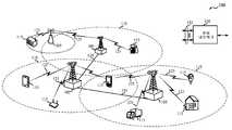
[0043]먼저 도 1을 참조하면, 블록도는 다양한 실시예들에 따른 무선 통신 시스템(100)을 예시한다. 무선 통신 시스템(100)은, 기지국들(또는 셀들)(105), 통신 디바이스들(115) 및 코어 네트워크(130)를 포함한다. 기지국들(105)은, 다양한 실시예들에서 코어 네트워크(130) 또는 기지국(105)의 일부일 수 있는 기지국 제어기(도시되지 않음)의 제어 하에서 통신 디바이스들(115)과 통신할 수 있다. 기지국들(105)은 백홀 링크들(132)을 통해 코어 네트워크(130)와 제어 정보 및/또는 사용자 데이터를 통신할 수 있다. 백홀 링크들(132)은 유선 백홀 링크들(예를 들어, 구리, 섬유 등) 및/또는 무선 백홀 링크들(예를 들어, 마이크로파 등)일 수 있다. 실시예들에서, 기지국들(105)은 유선 또는 무선 통신 링크들일 수 있는 백홀 링크들(134)을 통해 간접적으로 또는 직접적으로 서로 통신할 수 있다. 무선 통신 시스템(100)은 다수의 캐리어들(상이한 주파수들의 파형 신호들) 상에서의 동작을 지원할 수 있다. 다중-캐리어 송신기들은 변조된 신호들을 다수의 캐리어들 상에서 동시에 송신할 수 있다. 예를 들어, 각각의 통신 링크(125)는, 위에서 설명된 다양한 라디오 기술들에 따라 변조된 다중-캐리어 신호일 수 있다. 각각의 변조된 신호는 상이한 캐리어 상에서 전송될 수 있으며, 제어 정보(예를 들어, 기준 신호들, 제어 채널들 등), 오버헤드 정보, 데이터 등을 전달할 수 있다.[0043] Referring first to FIG. 1, a block diagram illustrates a
[0044]기지국들(105)은 하나 또는 그 초과의 기지국 안테나들을 통해 디바이스들(115)과 무선으로 통신할 수 있다. 기지국(105) 사이트들 각각은 각각의 커버리지 영역(110)에 대한 통신 커버리지를 제공할 수 있다. 일부 실시예들에서, 기지국들(105)은 베이스 트랜시버 스테이션, 라디오 기지국, 액세스 포인트, 라디오 트랜시버, BSS(basic service set), ESS(extended service set), NodeB, eNB(eNodeB), 홈 NodeB, 홈 eNodeB, 또는 일부 다른 적합한 용어로 지칭될 수 있다. 기지국에 대한 커버리지 영역(110)은 커버리지 영역의 일부분만을 구성하는 섹터들로 분할될 수 있다(도시되지 않음). 무선 통신 시스템(100)은 상이한 타입들의 기지국들(105)(예를 들어, 매크로, 마이크로 및/또는 피코 기지국들)을 포함할 수 있다. 상이한 기술들에 대한 오버랩핑 커버리지 영역들이 존재할 수 있다.[0044]
[0045]통신 디바이스들(115)은 무선 통신 시스템(100) 전역에 분산되고, 각각의 통신 디바이스는 고정식이거나 또는 이동식일 수 있다. 통신 디바이스(115)는 또한 당업자들에 의해 이동국, 가입자국, 모바일 유닛, 가입자 유닛, 무선 유닛, 원격 유닛, 모바일 디바이스, 무선 디바이스, 무선 통신 디바이스, 원격 디바이스, 모바일 가입자국, 액세스 단말, 모바일 단말, 무선 단말, 원격 단말, 핸드셋, 사용자 에이전트, 사용자 장비(UE), 모바일 클라이언트, 클라이언트, 또는 일부 다른 적합한 용어로 지칭될 수 있다. 통신 디바이스(115)는 MTC 디바이스, 셀룰러폰, PDA(personal digital assistant), 무선 모뎀, 무선 통신 디바이스, 핸드헬드 디바이스, 태블릿 컴퓨터, 랩탑 컴퓨터, 코드리스 폰, WLL(wireless local loop) 스테이션 등일 수 있다. 통신 디바이스는 매크로 기지국들, 피코 기지국들, 펨토 기지국들, 중계기 기지국들 등과 통신하는 것이 가능할 수 있다.[0045] The
[0046]무선 통신 시스템(100)에서 도시되는 송신 링크들(125)은 통신 디바이스(115)로부터 기지국(105)으로의 업링크(UL) 송신들 및/또는 기지국(105)으로부터 통신 디바이스(115)로의 다운링크(DL) 송신들을 포함할 수 있다. 다운링크 송신들은 또한 순방향 링크 송신들이라 칭해질 수 있는 한편, 업링크 송신들은 또한 역방향 링크 송신들이라 칭해질 수 있다.[0046] The transmission links 125 shown in the
[0047]실시예들에서, 무선 통신 시스템(100)은 LTE/LTE-A 네트워크이다. LTE/LTE-A 네트워크들에서, eNB(evolved Node B) 및 사용자 장비(UE)라는 용어들은 일반적으로 기지국들(105) 및 통신 디바이스들(115)을 각각 설명하기 위해 사용될 수 있다. 무선 통신 시스템(100)은, 상이한 타입들의 eNB들이 다양한 지리적 영역들에 대한 커버리지를 제공하는 이종(Heterogeneous) LTE/LTE-A 네트워크일 수 있다. 예를 들어, 각각의 eNB(105)는 매크로 셀, 피코 셀, 펨토 셀 및/또는 다른 타입들의 셀에 대한 통신 커버리지를 제공할 수 있다. 매크로 셀은 일반적으로, 비교적 넓은 지리적 영역(예를 들어, 반경 수 킬로미터)을 커버하며 네트워크 제공자에 서비스 가입들을 한 UE들에 의한 비제한적 액세스를 허용할 수 있다. 피코 셀은 일반적으로, 비교적 더 작은 지리적 영역을 커버할 것이며, 네트워크 제공자에 의한 서비스 가입들을 통해 UE들에 의한 비제한적 액세스를 허용할 수 있다. 펨토 셀은 또한 일반적으로, 비교적 작은 지리적 영역(예를 들어, 집)을 커버할 것이며, 비제한적 액세스와 더불어, 펨토 셀과의 연관을 갖는 UE들(예를 들어, CSG(closed subscriber group) 내의 UE들, 집에 있는 사용자들에 대한 UE들 등)에 의한 제한적 액세스를 또한 제공할 수 있다. 매크로 셀에 대한 eNB는 매크로 eNB로 지칭될 수 있다. 피코 셀에 대한 eNB는 피코 eNB로 지칭될 수 있다. 그리고 펨토 셀에 대한 eNB는 펨토 eNB 또는 홈 eNB로 지칭될 수 있다. eNB는 하나 또는 다수(예를 들어, 2개, 3개, 4개 등)의 셀들을 지원할 수 있다.[0047] In embodiments, the
[0048]LTE/LTE-A 네트워크 아키텍처에 따른 무선 통신 시스템(100)은 EPS(Evolved Packet System)(100)로 지칭될 수 있다. EPS(100)는, 하나 또는 그 초과의 UE들(115), E-UTRAN(Evolved UMTS Terrestrial Radio Access Network), EPC(Evolved Packet Core)(130)(예를 들어, 코어 네트워크(130)), HSS(Home Subscriber Server) 및 운영자의 IP 서비스들을 포함할 수 있다. EPS는, 다른 라디오 액세스 기술들을 사용하여 다른 액세스 네트워크들과 상호연결할 수 있다. 예를 들어, EPS(100)는, 하나 또는 그 초과의 SGSN(Serving GPRS Support Node)들을 통해 UTRAN-기반 네트워크 및/또는 CDMA-기반 네트워크와 상호연결할 수 있다. UE들(115)의 이동성 및/또는 로드 밸런싱을 지원하기 위해, EPS(100)는, 소스 eNB(105)와 타겟 eNB(105) 사이에서 UE들(115)의 핸드오버를 지원할 수 있다. EPS(100)는, 동일한 RAT(예를 들어, 다른 E-UTRAN 네트워크들)의 eNB들(105) 및/또는 기지국들 사이의 RAT-내 핸드오버, 및 상이한 RAT들(예를 들어, E-UTRAN에서 CDMA로 등)의 eNB들 및/또는 기지국들 사이의 RAT-간 핸드오버들을 지원할 수 있다. EPS(100)는 패킷-교환 서비스들을 제공할 수 있지만, 당업자들이 쉽게 인식할 바와 같이, 본 개시 내용 전반에 걸쳐 제시되는 다양한 개념들은 회선-교환 서비스들을 제공하는 네트워크들로 확장될 수 있다.The
[0049]E-UTRAN은 eNB들(105)을 포함할 수 있으며, UE들(115)을 향한 사용자 평면 및 제어 평면 프로토콜 종단들을 제공할 수 있다. eNB들(105)은 백홀 링크(134)(예를 들어, X2 인터페이스 등)를 통해 다른 eNB들(105)에 연결될 수 있다. eNB들(105)은, UE들(115)에 EPC(130)에 대한 액세스 포인트를 제공할 수 있다. eNB들(105)은 백홀 링크(132)(예를 들어, S1 인터페이스 등)에 의해 EPC(130)에 연결될 수 있다. EPC(130) 내의 로직 노드들은 하나 또는 그 초과의 MME들(Mobility Management Entities), 하나 또는 그 초과의 서빙 게이트웨이들, 및 하나 또는 그 초과의 PDN(Packet Data Network) 게이트웨이들(도시되지 않음)을 포함할 수 있다. 일반적으로, MME는 베어러 및 연결 관리를 제공할 수 있다. 모든 사용자 IP 패킷들은, 그 자체가 PDN 게이트웨이에 연결될 수 있는 서빙 게이트웨이를 통해 전달될 수 있다. PDN 게이트웨이는 UE IP 어드레스 할당 뿐만 아니라 다른 기능들을 제공할 수 있다. PDN 게이트웨이는 IP 네트워크들 및/또는 운영자의 IP 서비스들에 연결될 수 있다. 이러한 로직 노드들은 별개의 물리적 노드들로 구현될 수 있거나, 또는 하나 또는 그 초과의 로직 노드들이 단일의 물리적 노드로 결합될 수 있다. IP 네트워크들/운영자의 IP 서비스들은, 인터넷, 인트라넷, IMS(IP Multimedia Subsystem) 및/또는 PSS(Packet-Switched(PS) Streaming Service)를 포함할 수 있다.[0049] The E-UTRAN may include
[0050]UE들(115)은, 예를 들어, MIMO(Multiple Input Multiple Output), CoMP(Coordinated Multi-Point) 또는 다른 방식들을 통해 다수의 eNB들(105)과 협력적으로 통신하도록 구성될 수 있다. MIMO 기법들은 다중경로 환경들을 이용하여 다수의 데이터 스트림들을 송신하기 위해 기지국들 상의 다수의 안테나들 및/또는 UE 상의 다수의 안테나들을 사용한다. CoMP는, UE들에 대한 전반적 송신 품질을 개선하는 것 뿐만 아니라 네트워크 및 스펙트럼 활용도를 증가시키기 위해, 다수의 eNB들에 의한 송신 및 수신의 동적 조정을 위한 기법들을 포함한다. 일반적으로, CoMP 기법들은, UE들(115)에 대한 제어 평면 및 사용자 평면 통신들을 조정하기 위해, 기지국들(105) 사이의 통신들에 대해 백홀 링크들(132 및/또는 134)을 활용한다.[0050] The
[0051]다양한 개시되는 실시예들 중 일부를 수용할 수 있는 통신 네트워크들은, 계층화된 프로토콜 스택에 따라 동작하는 패킷-기반 네트워크들일 수 있다. 사용자 평면에서, 베어러 또는 PDCP(Packet Data Convergence Protocol) 계층에서의 통신들은 IP-기반일 수 있다. RLC(Radio Link Control) 계층은, 로직 채널들을 통해 통신하기 위해 패킷 세그먼트화 및 리어셈블리를 수행할 수 있다. MAC(Medium Access Control) 계층은, 로직 채널들의, 전송 채널들로의 멀티플렉싱 및 우선순위 핸들링을 수행할 수 있다. MAC 계층은 또한, 신뢰성 있는 데이터 송신을 보장하기 위해, MAC 계층에서 재송신을 제공하기 위한 HARQ(hybrid automatic repeat request) 기법들을 사용할 수 있다. 제어 평면에서, RRC(Radio Resource Control) 프로토콜 계층은, 사용자 평면 데이터에 대해 사용되는 네트워크와 UE 사이의 RRC 연결의 설정, 구성 및 유지를 제공할 수 있다. 물리 계층에서, 전송 채널들은 물리 채널들에 맵핑될 수 있다.[0051] Communication networks that may accommodate some of the various disclosed embodiments may be packet-based networks operating according to a layered protocol stack. In the user plane, the bearers or communications at the Packet Data Convergence Protocol (PDCP) layer may be IP-based. The Radio Link Control (RLC) layer may perform packet segmentation and reassembly to communicate over the logical channels. The MAC (Medium Access Control) layer may perform multiplexing and priority handling of the logical channels to the transport channels. The MAC layer may also use hybrid automatic repeat request (HARQ) techniques to provide retransmissions at the MAC layer to ensure reliable data transmission. In the control plane, the Radio Resource Control (RRC) protocol layer can provide for the establishment, configuration and maintenance of RRC connections between the network and the UEs used for user plane data. At the physical layer, transport channels can be mapped to physical channels.
[0052]무선 통신 시스템(100)은 커버리지 강화 기법들을 이용하도록 구성될 수 있다. 예를 들어, UE들(115) 중 하나 또는 그 초과의 UE들은 PRACH 반복 레벨과 같은 채널 반복 레벨에 기초하여 초기 업링크 전력을 결정할 수 있다. 그리고, UE(115)는 초기 업링크 전력에 따라 제 1 업링크 채널(예를 들어, PUSCH 또는 PUCCH)을 송신할 수 있다. 일부 경우들에서, 이것은 UE(115)가 채널 반복 레벨에 기초하여, 요청되는 전력 램프-업 오프셋을 결정하는 것을 포함한다. UE(115)는 요청되는 전력 램프-업 오프셋을 선택할 수 있거나, 또는 그것은 최대 전력 램프-업 값을 선택할 수 있으며, 이는 UE(115)는 업링크 전력을 계산하는데 사용할 수 있다.[0052] The
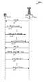
[0053]도 2a 및 도 2b는 다양한 실시예들에 따른 무선 통신 시스템 내에서의 통신을 도시하는 호 흐름도들(200-a 및 200-b)이다. 도면들(200-a 및 200-b)은 도 1의 무선 통신 시스템(100) 내에서 이용되는 업링크 전력 제어 커버리지 강화 기법들을 예시할 수 있다. 도면(200-a)은 UE(115-a) 및 eNB(105-a)를 포함하며, 이들은 도 1의 UE(115) 및 eNB(105)의 예들일 수 있다. UE(115-a)는 MTC 디바이스일 수 있고; UE(115-a) 및 eNB(105-a)는 커버리지 강화 기법들을 이용할 수 있다. 도면(200-a)은 경합-기반 PRACH 프로시저의 예일 수 있다. 예를 들어, 도면(200-a)은 UE(115-a)가 RRC 유휴 모드로부터 RRC 연결 모드로 트랜지션하고 있는 상황을 예시할 수 있다.[0053] Figures 2a and 2b are call flow diagrams 200-a and 200-b illustrating communications within a wireless communication system in accordance with various embodiments. The figures 200-a and 200-b may illustrate uplink power control coverage enforcement techniques utilized in the
[0054]UE(115-a)는 초기 PRACH 송신 전력으로 초기 PRACH 프리앰블(210-a)을 송신할 수 있다. PRACH 송신 전력은 최대 UE-송신 전력 값, 경로 손실 값 및 프리앰블 타겟 전력의 함수일 수 있다. 예를 들어, UE(115-a)는 PRACH 송신 전력으로서, 최대 UE-송신 전력 또는 경로 손실 값과 프리앰블 타겟 전력의 합 중 최소 값을 선택할 수 있다. 일부 경우들에서, 프리앰블 타겟 전력은 후속하는 PRACH 프리앰블 송신의 전력을 증가시키기 위해 UE(115-a)에 의해 사용될 수 있는 램핑 단계를 포함한다. 예를 들어, UE(115-a)가 초기 PRACH 프리앰블(210-a) 송신에 대한 응답을 수신하지 않으면, UE(115-a)는 PRACH 프리앰블 송신을 반복할 수 있다. 일부 수의 반복들 이후, UE(115-a)는 더 높은 반복 레벨로 스위칭할 수 있고, 그것은 제 n PRACH 프리앰블(210-n)을 송신할 수 있다. 제 n PRACH 프리앰블(210-n)은 초기 PRACH 프리앰블(210-a)보다 더 높은 PRACH 송신 전력으로 송신될 수 있다. 따라서, 초기 PRACH 프리앰블(210-a) 송신과 제 n PRACH 프리앰블(210-n) 송신 사이의 송신 전력의 차는 전력 램프-업을 표현할 수 있다. UE(115-a)는 그것이 성공적(또는 최종) PRACH 프리앰블(210-z)을 송신할 때까지 PRACH 프리앰블 송신들을 반복할 수 있다. 성공적 PRACH 프리앰블(210-z)은 제 3 채널 반복 레벨로 전송될 수 있으며, 이는 제 2 채널 반복 레벨에서 보다 더 높은 PRACH 전력으로 송신될 수 있다.The UE 115-a may transmit the initial PRACH preamble 210-a with the initial PRACH transmission power. The PRACH transmit power may be a function of the maximum UE-to-transmit power value, the path loss value and the preamble target power. For example, UE 115-a may select a minimum value of the sum of the maximum UE-transmit power or path loss value and the preamble target power as the PRACH transmit power. In some cases, the preamble target power includes a ramping step that may be used by UE 115-a to increase the power of the subsequent PRACH preamble transmission. For example, if UE 115-a does not receive a response to the initial PRACH preamble 210-a transmission, UE 115-a may repeat the PRACH preamble transmission. After some number of iterations, UE 115-a may switch to a higher repetition level, which may transmit the nth PRACH preamble 210-n. The nth PRACH preamble 210-n may be transmitted with a higher PRACH transmit power than the initial PRACH preamble 210-a. Thus, the difference in transmit power between the transmission of the initial PRACH preamble 210-a and the transmission of the n-th PRACH preamble 210-n may represent power ramp-up. UE 115-a may iterate the PRACH preamble transmissions until it successfully (or ultimately) transmits the PRACH preamble 210-z. A successful PRACH preamble 210-z may be transmitted at a third channel repetition level, which may be transmitted at a higher PRACH power than at the second channel repetition level.
[0055]성공적 PRACH 프리앰블(210-z)에 대한 응답으로, UE(115-a)는 eNB(105-a)로부터, 제어 정보를 포함하는 PDCCH(215) 및 RAR(random access response)를 포함하는 PDSCH(220)를 수신할 수 있다. UE(115-a)는 그 다음, PUSCH 상에서의 계층 3 메시지와 같은 초기 업링크 송신(225)에 대해 응답할 수 있다. 초기 업링크 전력 ― 예를 들어, 초기 업링크 송신(225)의 전력 ― 은 PRACH 반복 레벨에 적어도 부분적으로 기초하여 결정될 수 있다. 예를 들어, 초기 업링크 전력은 초기 PRACH 반복 레벨 또는 성공적(예를 들어, 제 3) PRACH 반복 레벨, 또는 둘다를 감안함으로써 결정될 수 있다. 그리고, 초기 업링크 송신(225)은 초기 업링크 전력에 따라 송신될 수 있다. 일부 경우들에서, UE(115-a)는 채널 반복 레벨(예를 들어, 하나 또는 그 초과의 PRACH 반복 레벨들)에 기초하여, 요청되는 전력 램프-업 오프셋을 결정하고, UE(115-a)는 요청되는 전력 램프-업 오프셋에 기초하여 업링크 전력을 계산한다. 추가적으로 또는 대안적으로, UE(115-a)는 (예를 들어, PDCCH(215) 상에서) eNB(105-a)로부터, UE(115-a)가 업링크 전력을 계산하기 위해 이용할 수 있는 송신 전력 제어 커맨드를 수신할 수 있다.In response to the successful PRACH preamble 210-z, the UE 115-a receives, from the eNB 105-a, a
[0056]일부 경우들에서, UE(115-a)는 다양한 반복 레벨들에 따라 업링크 송신들을 수행할 수 있다. 예를 들어, 제 n 업링크 송신(230)은 제 2 업링크 송신 반복 레벨에서 송신될 수 있다. 일부 실시예들에서, 제 n 업링크 송신(230)의 업링크 전력은 초기 업링크 전력이 기초하는 반복 레벨과 상이한 반복 레벨에 기초한다. 예를 들어, 후속하는 업링크 전력으로 지칭될 수 있는 제 n 업링크 송신(230)의 업링크 전력은 초기 업링크 송신(225)의 반복 레벨과 동일한 반복 레벨에 기초할 수 있다. 또 다른 예에서, 제 n 업링크 송신(230)은 초기 업링크 송신(225)의 반복 레벨과는 상이한 반복 레벨에 기초할 수 있다. 따라서, 제 n 업링크 송신(230)은 초기 업링크 송신(225)의 반복 레벨에 대해 그것의 반복 레벨에 기초하여 송신될 수 있다. 대안적으로, 제 n 업링크 송신(230)에 대한 반복 레벨이 임계치를 초과하는 경우, 최대 전력 값은 제 n 업링크 송신(230)에 대해 적용될 수 있고, 업링크 송신은 최대 전력 값(예를 들어, 최대 UE-송신 전력)을 사용하여 송신될 수 있다.[0056] In some cases, UE 115-a may perform uplink transmissions in accordance with various repetition levels. For example, the n
[0057]다음으로, 도 2b의 도면(200-b)은 비-경합-기반 PRACH 프로시저에서의 UE의 예일 수 있다. 도면(200-b)은 도 1의 UE(115) 및 eNB(105)의 예들일 수 있는 UE(115-b) 및 eNB(105-b)를 포함한다. UE(115-b)는 MTC 디바이스일 수 있고; UE(115-b) 및 eNB(105-b)는 커버리지 강화 기법들을 이용할 수 있다. 예를 들어, 도면(200-b)은, eNB(105-b)가 UE(115-b)에 송신할 다운링크 데이터를 가지는 반면 UE(115-b)가 비-동기화되는 시나리오를 예시할 수 있다.[0057] Next, the diagram 200-b of FIG. 2B may be an example of a UE in a non-contention-based PRACH procedure. The diagram 200-b includes UE 115-b and eNB 105-b, which may be examples of
[0058]UE(115-b)는 eNB(105-b)로부터, 특정 PRACH 자원 및/또는 업링크 전력 파라미터(예를 들어, 요청되는 전력 램프-업 오프셋)의 표시를 표시하는 제어 정보를 포함할 수 있는 PDCCH(250)를 수신할 수 있다. 그 다음, UE(115-b)는 도 2a를 참조하여 설명되는 것과 거의 동일한 PRACH 프로시저를 통해 진행할 수 있다. UE(115-b)는 초기 PRACH 프리앰블(255-a), 제 n PRACH 프리앰블(255-n), 및/또는 성공적 PRACH 프리앰블(255-z)을 송신할 수 있다. 이들 각각은 다양한 반복 레벨들에 따라 송신될 수 있고, 각각은 전력 램프-업에 따라 송신될 수 있다. UE(115-b)는 PDCCH(260) 및 RAR을 포함하는 PDSCH(265)를 수신할 수 있다. 그리고, UE(115-b)는 그 다음, 초기 업링크 송신(270) 및 제 n 업링크 송신(280)에 대해 응답할 수 있다. 업링크 송신들(270, 280)은 PUSCH 상에서의 계층 3 메시지일 수 있다. 초기 업링크 전력 ― 예를 들어, 초기 업링크 송신(270)의 전력 ― 은 PRACH 반복 레벨에 적어도 부분적으로 기초하여 결정할 수 있다. 추가적으로 또는 대안적으로, 초기 업링크 전력은 eNB(105-b)로부터 표시되는 요청되는 전력 램프-업 오프셋에 부분적으로 기초하여 결정될 수 있다.[0058] The UE 115-b includes control information from the eNB 105-b indicating the indication of a particular PRACH resource and / or uplink power parameter (eg, the requested power ramp-up offset) PDCCH < / RTI > The UE 115-b may then proceed through a PRACH procedure that is substantially the same as that described with reference to FIG. 2A. UE 115-b may transmit an initial PRACH preamble 255-a, an n-th PRACH preamble 255-n, and / or a successful PRACH preamble 255-z. Each of these can be transmitted according to various repetition levels, and each can be transmitted in accordance with the power ramp-up. UE 115-b may receive
[0059]이제, 도 3a를 참조하면, 다양한 실시예들에 따른, 업링크 전력 제어를 위해 구성되는 예시적 디바이스(305)의 블록도(300)가 도시된다. 디바이스(305)는 도 1, 도 2a 및 도 2b를 참조하여 설명되는 UE들(115) 및/또는 eNB들(105)의 양상들의 예일 수 있다. 디바이스(305)는 수신기 모듈(310), 제어기 모듈(320) 및/또는 송신기 모듈(330)을 포함할 수 있다. 이 모듈들 각각은 서로 통신할 수 있고; 다양한 모듈들은 본원에서 설명되는 기능들을 수행하기 위한 수단일 수 있다. 일부 실시예들에서, 디바이스(305)의 하나 또는 그 초과의 양상들은 프로세서이다.[0059] Referring now to FIG. 3A, a block diagram 300 of an
[0060]수신기 모듈(310)은 다양한 채널들 및 메시지들을 수신하도록 구성될 수 있다. 예를 들어, 수신기 모듈(310)은 UE(115)로부터, PRACH, PUSCH, PUCCH 및/또는 SRS를 수신하도록 구성될 수 있다. 다른 실시예들에서, 수신기 모듈(310)은 eNB(105)로부터 PDCCH, RAR, TPC 메시지들, 및 추가 데이터 및 제어 정보를 수신하도록 구성된다.[0060] The
[0061]제어기 모듈(320)은 전력 레벨들 및 반복 레벨들과 관련된 파라미터들, 세팅들 및 값들을 결정, 식별, 선택 및/또는 계산하도록 구성될 수 있다. 예를 들어, 제어기 모듈(320)은 반복 레벨에 전체적으로 또는 부분적으로 기초하여 업링크 전력을 결정하도록 구성될 수 있다. 따라서, 제어기 모듈(320)은 제 1 반복 레벨 및 제 2 반복 레벨에 기초하여 초기 업링크 전력 레벨 및 후속하는 전력 레벨을 각각 결정할 수 있다. 예로서, 반복 레벨들은 PRACH, PUSCH, PUCCH 및/또는 SRS 반복 레벨들일 수 있고; 업링크 전력 레벨들은 PRACH, PUSCH, PUCCH 및/또는 SRS 전력 레벨들일 수 있다.[0061]
[0062]송신기 모듈(330)은 결정되는 반복 레벨 또는 전력 레벨, 또는 둘다에 따라 채널들 및 메시지들을 송신하도록 구성될 수 있다. 예를 들어, 송신기 모듈(330)은 PRACH, PUSCH, PUCCH 및/또는 SRS를 eNB(105)에 송신하거나 또는 이들을 반복적으로 송신하도록 구성될 수 있다. 대안적으로, 송신기 모듈(330)은 PDCCH, RAR, TPC 메시지들, 및 추가 데이터 및 제어 정보를 UE(115)에 송신하거나 또는 이들을 반복적으로 송신하도록 구성될 수 있다. 일부 실시예들에서, 송신기 모듈(330)은 제어기 모듈(320)에 의해 결정되는 초기 업링크 전력에 따라 하나 또는 그 초과의 업링크 채널들을 송신하도록 구성된다. 마찬가지로, 송신기 모듈(330)은 제어기 모듈(320)에 의해 결정되는 후속하는 업링크 전력에 따라 하나 또는 그 초과의 업링크 채널들을 송신하도록 구성될 수 있다.[0062] The
[0063]그 다음, 도 3b는 다양한 실시예들에 따른 업링크 전력 제어를 위해 구성되는 예시적 디바이스(305-a)의 블록도(300-a)를 도시한다. 디바이스(305-a)는 도 3a의 디바이스(305)의 예일 수 있고; 그것은 도 1, 도 2a 및 도 2b를 참조하여 설명되는 UE들(115) 및/또는 eNB들(105)의 양상들의 예일 수 있다. 디바이스(305)는 수신기 모듈(310-a), 제어기 모듈(320-a) 및/또는 송신기 모듈(330-a)을 포함할 수 있다. 이 모듈들 각각은 서로 통신할 수 있고, 이들은 도 3a의 대응하는 모듈들의 예들일 수 있다. 디바이스(305-a)의 다양한 모듈들은 본원에서 설명되는 기능들을 수행하기 위한 수단일 수 있다. 추가적으로, 디바이스(305-a)의 하나 또는 그 초과의 양상들은 프로세서일 수 있다.[0063] FIG. 3B then shows a block diagram 300-a of an exemplary device 305-a configured for uplink power control in accordance with various embodiments. The device 305-a may be an example of the
[0064]제어기 모듈(320-a)은 전력 결정 모듈(340) 및/또는 반복 결정 모듈(350)을 포함할 수 있다. 이 모듈들 각각은 서로 통신할 수 있고, 이들 각각은 프로세서의 양상일 수 있다. 전력 결정 모듈(340)은 채널 반복 레벨에 전체적으로 또는 부분적으로 기초하여 업링크 전력을 결정하도록 구성될 수 있다. 예를 들어, 전력 결정 모듈(340)은 하나의 채널 반복 레벨(예를 들어, PRACH 반복 레벨)에 기초하여 초기 업링크 전력을 결정하도록 구성될 수 있고, 그것은 상이한 채널 반복 레벨(예를 들어, PUSCH 반복 레벨)에 기초하여 후속하는 업링크 전력을 결정하도록 구성될 수 있다. 그리고, 송신기 모듈(330-a)은 결정되는 업링크 전력에 따라 업링크 채널들을 송신할 수 있다.[0064] Controller module 320-a may include
[0065]예로서, 전력 결정 모듈(340)은 전력 램프-업 값(예를 들어, 전력 램프-업 오프셋) 또는 전력 조정 값을 감안하거나 또는 이를 활용하는 업링크 전력을 결정하도록 구성될 수 있다. 전력 결정 모듈(340)은, 예를 들어, 오프셋에 기초하여, 요청되는 전력 램프-업 오프셋을 결정할 수 있다. 추가적으로 또는 대안적으로, 전력 결정 모듈(340)은 PUSCH 송신들, PUCCH 송신들, SRS 송신들, 또는 이들의 결합에 대한 반복 레벨들의 차에 기초하여 전력 조정 값을 결정할 수 있다. 그것은 또한, 요청되는 전력 램프-업 오프셋 및 최대 전력 램프-업 값을 포함하는 세트로부터의 최소 값을 선택할 수 있다. 그리고, 그것은 선택되는 최소치, 및 일부 경우들에서는, TPC 커맨드에 기초하여 업링크 전력을 계산할 수 있다. 이 결정들은 (예를 들어, 수신기 모듈(310-a)을 통해) 다른 시스템 노드들로부터 수신되고 전력 결정 모듈(340)로 전달되는 파라미터들에 어느 정도 기초할 수 있다.[0065] As an example, the
[0066]반복 결정 모듈(350)은 다양한 송신들 (예를 들어, PRACH, PUSCH, PUCCH, SRS 등)에 대한 반복 레벨을 결정하도록 구성될 수 있거나, 또는 그것은 레벨당 반복들의 수를 결정할 수 있거나, 또는 그것은 둘다를 결정할 수 있다. 일부 경우들에서, 레벨당 반복들의 수 및/또는 가능한 반복 레벨들은 제어기 모듈(320-a)에 의해 선험적으로 알려지고, 반복 결정 모듈(350)은 알려진 값들로부터 레벨 및/또는 반복 수를 결정한다. 다른 실시예들에서, 반복 레벨들 및/또는 레벨당 반복들의 수들은 반복 모듈(350)에 의해 결정될 수 있는 구성가능한 값들이다. 여전히 다른 실시예들에서, 반복 레벨들 및/또는 레벨당 반복들의 수는 구성가능한 값들이고, 이들은 또 다른 디바이스(예를 들어, eNB)에서 구성가능하며, 반복 결정 모듈(350)로 전달된다. 예를 들어, 수신기 모듈(310-a)은 주어진 채널에 대한 반복 레벨들 및/또는 반복들의 수들을 표시하는 시그널링을 수신할 수 있고, 수신기 모듈(310-a)은 이러한 정보를 반복 결정 모듈(350)로 전달할 수 있다.[0066] The
[0067]일부 실시예들에서, 전력 결정 모듈(340)은 3GPP 규격들에 의해 기술되는 바와 같이 업링크 전력을 결정하지만, 결정 모듈(340)은 반복 레벨에 적어도 부분적으로 기초하여 업링크 전력을 결정할 수 있다. 예를 들어, UE(115)가 서빙 셀 c에 대한 RAR을 수신하면, 초기 PUSCH 전력

여기서,

이고,ego,
여기서,here,

이고, 여기서,


[0068]PUSCH에 대해, 요청되는 전력 램프-업 오프셋은 다음과 같이 정의될 수 있다:[0068] For PUSCH, the requested power ramp-up offset may be defined as:

여기서,


[0069]위의 내용을 고려하면, PUSCH 반복 레벨이 (예를 들어, 반복 결정 모듈(350)에 의해) 변경됨에 따라,


[0070]초기 PUCCH 전력

여기서, PUCCH가 PUSCH와 동일한 서브프레임에서 송신되면,Here, if the PUCCH is transmitted in the same subframe as the PUSCH,

그리고And

이다. 그렇지 않으면,to be. Otherwise,

수식들 7-9에서:


[0071]PUCCH에 대해, 요청되는 전력 램프-업 오프셋은 다음과 같이 정의될 수 있다:[0071] For PUCCH, the requested power ramp-up offset can be defined as:

여기서,


[0072]일부 실시예들에서, PUSCH 및 PUCCH 반복 레벨들 및/또는 레벨당 반복들의 수 중 어느 하나 또는 둘다는 후속하는 송신들 사이에서 조정가능하다. 예를 들어, 반복 결정 모듈(350)은 송신들 사이의 PUSCH 및/또는 PUCCH 반복 레벨들을 조정할 수 있다. 따라서, 전력 결정 모듈(340)은 상이한 반복 레벨들(또는 레벨당 반복들의 수)을 보상하거나 또는 이에 대해 조정하도록 구성될 수 있다. 예를 들어, 전력 결정 모듈(340)은 다음과 같은 PUSCH 및/또는 PUCCH 전력 제어에 대한 전력 오프셋 δ을 결정할 수 있다:[0072] In some embodiments, either or both of the PUSCH and PUCCH repetition levels and / or the number of iterations per level are adjustable between subsequent transmissions. For example, the

여기서,

[0073]전력 결정 모듈(340)은 또한, SRS 전력 제어를 위해 구성될 수 있다. 일부 경우들에서, SRS 송신 전력은 결정되는 PUSCH 송신 전력에 비례할 수 있고; 일부 실시예들에서, SRS 송신 전력은 PUSCH 송신 전력 및 오프셋에 기초할 수 있다. 예를 들어, SRS 송신 전력은 네트워크에 의해 표시되는 파라미터 및/또는 반복 레벨 기반 조정(예를 들어, PUSCH 반복 레벨 및 SRS 레벨의 비교)에 기초하는 오프셋에 기초할 수 있다. 다른 경우들에서, 전력 결정 모듈(340)은 SRS를 송신할 것인 최대 송신 값(예를 들어,
[0074]도 3c는 다양한 실시예들에 따른, 업링크 전력 제어를 위해 구성되는 예시적 디바이스(305-b)의 블록도(300-b)를 도시한다. 디바이스(305-b)는 도 3a 및 도 3b의 디바이스들(305)의 예일 수 있고; 그것은 도 1, 도 2a 및 도 2b를 참조하여 설명되는 UE들(115) 및/또는 eNB들(105)의 양상들의 예일 수 있다. 디바이스(305-b)는 수신기 모듈(310-b), 제어기 모듈(320-b), 및/또는 송신기 모듈(330-b)을 포함할 수 있다. 이 모듈들 각각은 서로 통신할 수 있고, 이들은 도 3a 및 도 3b의 대응하는 모듈들의 예들일 수 있다. 디바이스(305-b)의 다양한 모듈들은 본원에 설명되는 기능들을 수행하기 위한 수단일 수 있다. 추가적으로, 디바이스(305-b)의 하나 또는 그 초과의 양상들은 프로세서일 수 있다.[0074] FIG. 3C shows a block diagram 300-b of an example device 305-b configured for uplink power control, in accordance with various embodiments. The device 305-b may be an example of the
[0075]디바이스(305-b)는 전력 결정 모듈(340-a)을 포함할 수 있으며, 이는 오프셋 결정 모듈(360), 선택 모듈(370) 및/또는 송신 전력 계산 모듈(380)을 더 포함할 수 있다. 추가적으로 또는 대안적으로, 디바이스(305-b)는 반복 결정 모듈(350-a)을 포함할 수 있으며, 이는 임계치 식별 모듈(390)을 더 포함할 수 있다. 다양한 모듈들 각각은 서로 통신할 수 있다.The device 305-b may include a power determination module 340-a, which further includes an offset
[0076]오프셋 결정 모듈(360)은, 반복 레벨에 기초하여, 요청되는 전력 램프-업 오프셋 또는 전력 조정 오프셋을 결정하도록 구성될 수 있다. 예를 들어, 오프셋 결정 모듈(360)은 수식 4, 수식 5, 수식 10 및 수식 11 중 하나 또는 그 초과의 수식들을 이용할 수 있다. 추가적으로 또는 대안적으로, 오프셋 결정 모듈(360)은 또 다른 시스템 노드(예를 들어, eNB(105))로부터 (예를 들어, 수신기 모듈(310-b)을 통해) 수신된 표시에 기초하여, 요청되는 오프셋을 결정하도록 구성될 수 있다.[0076] The offset
[0077]선택 모듈(370)은 요청되는 전력 램프-업 오프셋 및 최대 전력 램프-업 값을 포함하는 세트의 최소치를 선택하도록 구성될 수 있다. 다양한 실시예들에서, 선택 모듈(370)은 수식 2, 수식 3, 수식 7, 수식 8 및 수식 9 중 하나 또는 그 초과의 수식들을 이용하도록 구성된다.[0077] The
[0078]일부 실시예들에서, 송신 전력 계산 모듈(380)은 선택된 최소치 및 TPC 커맨드에 기초하여 업링크 전력을 계산하도록 구성된다. 예를 들어, 송신 전력 계산 모듈(380)은 업링크 전력을 결정하기 위해 수식 1 및/또는 수식 6을 이용할 수 있다. 그 다음, 송신기 모듈(330-b)은 계산된 업링크 전력에 따라, 하나 또는 그 초과의 채널들, 신호들 또는 메시지들을 (예를 들어, 업링크 상에서) eNB(105)에 송신할 수 있다. 또는, 송신기 모듈(330-c)은 계산된 업링크 전력과 관련된 파라미터들, 세팅들 및 또는 값들을 (예를 들어, 다운링크 상에서) UE(115)에 송신하도록 구성될 수 있다.[0078] In some embodiments, the transmit
[0079]임계치 식별 모듈(390)은 하나 또는 그 초과의 반복 임계치들을 식별하도록 구성될 수 있다. 따라서, 그것은 최대 송신 전력이 사용되어야 하는 반복 임계치를 식별할 수 있다. 예를 들어, 전력 결정 모듈(340-a)은, 반복 레벨이 일부 미리 결정된 값보다 크면(예를 들어, 레벨 4보다 큼), 송신기 모듈(330-b)로 하여금
[0080]디바이스들(305)의 컴포넌트들은 하드웨어에서 적용가능한 기능들 중 일부 또는 그 전부를 수행하도록 적응되는 하나 또는 그 초과의 ASIC(application-specific integrated circuit)들로 개별적으로 또는 집합적으로 구현될 수 있다. 대안적으로, 기능들은 하나 또는 그 초과의 집적 회로들 상에서, 하나 또는 그 초과의 다른 프로세싱 유닛들(또는 코어들)에 의해 수행될 수 있다. 다른 실시예들에서, 다른 타입들의 집적 회로들(예를 들어, 구조화된/플랫폼 ASIC들, FPGA(Field Programmable Gate Array)들 및 다른 반-주문형(Semi-Custom) IC들)이 사용될 수 있으며, 이들은 당해 기술 분야에서 알려진 임의의 방식으로 프로그래밍될 수 있다. 각각의 유닛의 기능들은 또한, 하나 또는 그 초과의 일반형 또는 주문형 프로세서들에 의해 실행되도록 포맷된, 메모리 내에 구현되는 명령들로 전체적으로 또는 부분적으로 구현될 수 있다.[0080] The components of the
[0081]다음으로, 도 4를 참조하면, 이는 다양한 실시예들에 따른, 업링크 전력 제어를 위해 구성되는 예시적 UE(115-c)의 블록도(400)를 도시한다. UE(115-c)는 MTC 디바이스일 수 있고, 그리고/또는 그것은 개인용 컴퓨터들(예를 들어, 랩탑 컴퓨터들, 넷북 컴퓨터들, 태블릿 컴퓨터들 등), 셀룰러 전화들, PDA들, 스마트폰들, DVR(digital video recorder)들, 인터넷 어플라이언스들, 게이밍 콘솔들, e-리더들 등과 같은 다양한 구성들 중 임의의 것을 가질 수 있다. UE(115-c)는 모바일 동작을 가능하게 하기 위해 소형 배터리와 같은 내부 파워 서플라이(도시되지 않음)를 가질 수 있다. 일부 실시예들에서, UE(115-c)는 도 1, 도 2a 및 도 2b의 UE들(115)의 예일 수 있다.[0081] Next, with reference to FIG. 4, which shows a block diagram 400 of an exemplary UE 115-c configured for uplink power control, in accordance with various embodiments. UE 115-c may be an MTC device and / or it may be a personal computer (e.g., laptop computers, netbook computers, tablet computers, etc.), cellular phones, PDAs, smart phones, Digital video recorders (DVRs), Internet appliances, gaming consoles, e-readers, and the like. UE 115-c may have an internal power supply (not shown), such as a miniature battery, to enable mobile operation. In some embodiments, the UE 115-c may be an example of the
[0082]UE(115-c)는 일반적으로, 통신들을 송신하기 위한 컴포넌트들 및 통신들을 수신하기 위한 컴포넌트들을 포함하는, 양방향 음성 및 데이터 통신들을 위한 컴포넌트들을 포함할 수 있다. UE(115-c)는 안테나(들)(405), 트랜시버 모듈(410), 프로세서 모듈(470) 및 메모리(480)(소프트웨어(SW)(485)를 포함함)를 포함할 수 있으며, 이들은 각각 (예를 들어, 하나 또는 그 초과의 버스들(490)을 통해) 간접적으로 또는 직접적으로 서로 통신할 수 있다. 트랜시버 모듈(410)은 위에서 설명된 바와 같이, 안테나(들)(405) 및/또는 하나 또는 그 초과의 유선 또는 무선 링크들을 통해 하나 또는 그 초과의 네트워크들과 양방향으로 통신하도록 구성될 수 있다. 예를 들어, 트랜시버 모듈(410)은 도 1, 도 2a 및/또는 도 2b의 eNB들(105)과 양방향으로 통신하도록 구성될 수 있다. 트랜시버 모듈(410)은 패킷들을 변조하고, 송신을 위해 안테나(들)(405)에 변조된 패킷들을 제공하고, 안테나(들)(405)로부터 수신된 패킷들을 복조하도록 구성되는 모뎀을 포함할 수 있다. UE(115-c)는 단일 안테나(405)를 포함할 수 있지만, UE(115-c)는 다수의 무선 송신들을 동시에 송신 및/또는 수신할 수 있는 다수의 안테나들(405)을 가질 수 있다. 트랜시버 모듈(410)은 다수의 컴포넌트 캐리어들을 통해 다수의 eNB들(105)과 동시에 통신할 수 있다.[0082] The UE 115-c may generally include components for two-way voice and data communications, including components for transmitting communications and components for receiving communications. UE 115-c may include antenna (s) 405, transceiver module 410,
[0083]메모리(480)는 RAM(random access memory) 및 ROM(read-only memory)을 포함할 수 있다. 메모리(480)는 실행될 때, 프로세서 모듈(470)로 하여금 본원에서 설명되는 다양한 기능들(예를 들어, 호 프로세싱, 데이터베이스 관리, 핸드오버 지연의 캡처 등)을 수행하게 하도록 구성되는 명령들을 포함하는 컴퓨터 판독가능한, 컴퓨터 실행가능한 소프트웨어/펌웨어 코드(485)를 저장할 수 있다. 대안적으로, 소프트웨어/펌웨어 코드(485)는 프로세서 모듈(470)에 의해 직접적으로 실행가능하지 않을 수 있지만, (예를 들어, 컴파일링 및 실행될 때) 컴퓨터로 하여금 본원에서 설명되는 기능들을 수행하게 하도록 구성될 수 있다.[0083] The memory 480 may include random access memory (RAM) and read-only memory (ROM). The memory 480 includes instructions that when executed are configured to cause the
[0084]프로세서 모듈(470)은 지능형 하드웨어 디바이스, 예를 들어, CPU(central processing unit), 마이크로제어기, ASIC(application-specific integrated circuit) 등을 포함할 수 있다. UE(115-c)는 마이크로폰을 통해 오디오를 수신하고, 오디오를 수신된 오디오를 표현하는 패킷들(예를 들어, 20ms의 길이, 30ms의 길이 등)로 변환하고, 오디오 패킷들을 트랜시버 모듈(410)에 제공하고, 그리고 사용자가 말하고 있는지 여부에 대한 표시들을 제공하도록 구성되는 스피치 인코더(도시되지 않음)를 포함할 수 있다.[0084] The
[0085]도 4의 아키텍처에 따라, UE(115-c)는 전력 결정 모듈(340-b) 및/또는 반복 결정 모듈(350-b)을 더 포함할 수 있고, 이는 도 3b 및 도 3c의 전력 결정 모듈들(340) 및 반복 결정 모듈들(350)과 실질적으로 동일할 수 있다. 일부 경우들에서, 전력 결정 모듈(340-b)은 도 3c의 모듈들(360, 370 및 380)의 기능들을 수행하도록 구성되고, 반복 결정 모듈(350-b)은 도 3c의 모듈(390)의 기능들을 수행하도록 구성된다. 예로서, 전력 결정 모듈(340-b) 및/또는 반복 결정 모듈(350-b)은 버스(490)를 통해 UE(115-c)의 다른 컴포넌트들 중 일부 또는 그 전부와 통신하는 UE(115-c)의 컴포넌트들일 수 있다. 대안적으로, 이 모듈들의 기능은 트랜시버 모듈(410)의 컴포넌트로서, 컴퓨터 프로그램 물건으로서 그리고/또는 프로세서 모듈(470)의 하나 또는 그 초과의 제어기 엘리먼트들로서 구현될 수 있다.In accordance with the architecture of FIG. 4, the UE 115-c may further include a power determination module 340-b and / or an iteration determination module 350-b,
[0086]다음으로, 도 5는 다양한 실시예들에 따른, 업링크 전력 제어를 위해 구성되는 예시적 무선 통신 시스템(500)의 블록도를 도시한다. 이 시스템(500)은 도 1에 도시되는 무선 통신 시스템(100)의 양상들의 예일 수 있다. 무선 통신 시스템(500)은 무선 통신 링크들(125)을 통한 UE들(115)과의 통신을 위해 구성되는 eNB(105-c)를 포함한다. eNB(105-c)는 다른 기지국들(도시되지 않음)로부터 통신 링크들(125)을 수신할 수 있다. eNB(105-c)는, 예를 들어, 도 1, 도 2a 및 도 2b에 예시되는 바와 같은 eNB(105)일 수 있다.[0086] Next, FIG. 5 shows a block diagram of an exemplary
[0087]일부 경우들에서, eNB(105-c)는 하나 또는 그 초과의 유선 백홀 링크들을 가질 수 있다. eNB(105-c)는, 예를 들어, 코어 네트워크(130-a)로의 유선 백홀 링크(예를 들어, S1 인터페이스 등)를 갖는 마이크로 eNB(105)일 수 있다. eNB(105-c)는 또한, 기지국-간 통신 링크들(예를 들어, X2 인터페이스 등)을 통해 기지국(105-m) 및 기지국(105-n)과 같은 다른 기지국들(105)과 통신할 수 있다. 기지국들(105) 각각은 동일한 또는 상이한 무선 통신 기술들을 사용하여 UE들(115)과 통신할 수 있다. 일부 경우들에서, eNB(105-c)는 기지국 통신 모듈(515)을 활용하여 105-m 및/또는 105-n과 같은 다른 기지국들과 통신할 수 있다. 일부 실시예들에서, 기지국 통신 모듈(515)은 기지국들(105) 중 일부 기지국들 사이의 통신을 제공하기 위해 LTE/LTE-A 무선 통신 네트워크 기술 내에서의 X2 인터페이스를 제공할 수 있다. 일부 실시예들에서, eNB(105-c)는 코어 네트워크(130-a)를 통해 다른 기지국들과 통신할 수 있다. 일부 경우들에서, eNB(105-c)는 네트워크 통신 모듈(565)을 통해 코어 네트워크(130-a)와 통신할 수 있다.[0087] In some cases, the eNB 105-c may have one or more wired backhaul links. The eNB 105-c may be, for example, a micro-eNB 105 having a wired backhaul link (e.g., an S1 interface, etc.) to the core network 130-a. eNB 105-c may also communicate with
[0088]eNB(105-c)에 대한 컴포넌트들은 도 1, 도 2a 및 도 2b의 eNB들(105) 및/또는 도 3a, 도 3b 및 도 3c의 디바이스들(305)에 대해 위에서 논의된 양상들을 구현하도록 구성될 수 있으며, 간결함을 위해 여기서 반복되지 않을 수 있다. 예를 들어, eNB(105-c)는 하나 또는 그 초과의 반복 레벨들에 전체적으로 또는 부분적으로 기초하여 업링크 전력을 결정하도록 구성될 수 있다. 일부 실시예들에서, eNB(105-c)는 전력 램프-업 오프셋을 UE(115)로 표시하도록 구성된다.[0088] The components for eNB 105-c are the same as those discussed above for
[0089]기지국(105-c)은 안테나들(545), 트랜시버 모듈들(550), 프로세서 모듈(560) 및 메모리(570)(소프트웨어(SW)(575)를 포함함)를 포함할 수 있고, 이들 각각은 (예를 들어, 버스 시스템(580)을 통해) 간접적으로 또는 직접적으로 서로 통신할 수 있다. 트랜시버 모듈들(550)은, MTC 디바이스들일 수 있는 UE들(115)과 안테나들(545)을 통해 양방향으로 통신하도록 구성될 수 있다. 트랜시버 모듈(550)(및/또는 eNB(105-c)의 다른 컴포넌트들)은 또한, 안테나들(545)을 통해 하나 또는 그 초과의 다른 기지국들(도시되지 않음)과 양방향으로 통신하도록 구성될 수 있다. 트랜시버 모듈(550)은, 패킷들을 변조하고, 변조된 패킷들을 송신을 위해 안테나들(545)에 제공하고, 안테나들(545)로부터 수신된 패킷들을 복조하도록 구성되는 모뎀을 포함할 수 있다. 기지국(105-c)은 다수의 트랜시버 모듈들(550)을 포함할 수 있고, 이들 각각은 하나 또는 그 초과의 연관된 안테나들(545)을 갖는다.The base station 105-c may include
[0090]메모리(570)는 RAM(random access memory) 및 ROM(read-only memory)을 포함할 수 있다. 메모리(570)는 또한, 명령들을 포함하는 컴퓨터 판독가능한, 컴퓨터 실행가능한 소프트웨어 코드(575)를 저장할 수 있고, 명령들은, 실행될 때, 프로세서 모듈(560)로 하여금, 본 명세서에서 설명되는 다양한 기능들(예를 들어, 전력 결정, 호 프로세싱, 데이터베이스 관리, 메시지 라우팅 등)을 수행하게 하도록 구성된다. 대안적으로, 소프트웨어(575)는, 프로세서 모듈(560)에 의해 직접적으로 실행가능하지는 않을 수 있지만, 예를 들어, 컴파일 및 실행될 때, 컴퓨터로 하여금, 본 명세서에서 설명되는 기능들을 수행하게 하도록 구성될 수 있다.[0090] The memory 570 may include random access memory (RAM) and read-only memory (ROM). The memory 570 may also store computer readable, computer
[0091]프로세서 모듈(560)은 지능형 하드웨어 디바이스, 예를 들어, CPU(central processing unit), 마이크로제어기, ASIC(application-specific integrated circuit) 등을 포함할 수 있다. 프로세서 모듈(560)은, 인코더들, 큐 프로세싱 모듈들, 기저대역 프로세서들, 라디오 헤드 제어기들, DSP(digital signal processor)들 등과 같은 다양한 특수 목적 프로세서들을 포함할 수 있다.[0091] The processor module 560 may include an intelligent hardware device, such as a central processing unit (CPU), a microcontroller, an application-specific integrated circuit (ASIC), or the like. The processor module 560 may include various special purpose processors such as encoders, cue processing modules, baseband processors, radio head controllers, digital signal processors (DSPs), and the like.
[0092]도 5의 아키텍처에 따르면, eNB(105-c)는 통신 관리 모듈(540)을 더 포함할 수 있다. 통신 관리 모듈(540)은 다른 기지국들(105)과의 통신들을 관리할 수 있다. 통신 관리 모듈은, 다른 기지국들(105)과 협력하여 UE들(115)과의 통신들을 제어하기 위한 제어기 및/또는 스케줄러를 포함할 수 있다. 예를 들어, 통신 관리 모듈(540)은, 빔형성 및/또는 조인트 송신과 같은 다양한 간섭 완화 기법들 및/또는 UE들(115)로의 송신들을 위한 스케줄링을 수행할 수 있다.[0092] According to the architecture of FIG. 5, the eNB 105-c may further include a
[0093]추가적으로 또는 대안적으로, eNB(105-c)는 도 3b 및 도 3c의 모듈들(340)과 실질적으로 동일하게 구성될 수 있는 전력 결정 모듈(340-c)을 포함할 수 있다. 일부 경우들에서, 전력 결정 모듈(340-c)은, 도 3c의 모듈들(360, 370 및/또는 380)의 기능들을 수행하도록 구성된다. 일부 실시예들에서, 전력 결정 모듈(340-c)은 버스(580)를 통해 eNB(105-c)의 다른 컴포넌트들 중 일부 또는 그 전부와 통신하는 eNB(105-c)의 컴포넌트이다. 대안적으로, 전력 결정 모듈(340-c)의 기능은, 트랜시버 모듈(550)의 컴포넌트로서, 컴퓨터 프로그램 물건으로서, 프로세서 모듈(560)의 하나 또는 그 초과의 제어기 엘리먼트들로서, 그리고/또는 통신 관리 모듈(540)의 엘리먼트로서 구현될 수 있다.[0093] Additionally or alternatively, the eNB 105-c may include a power determination module 340-c that may be configured substantially the same as the
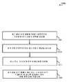
[0094]도 6에서, 다양한 실시예들에 따른 업링크 전력 제어를 위한 방법(600)의 흐름도가 도시된다. 방법(600)은 도 1, 도 2a, 도 2b 및/또는 도 4의 UE들(115) 중 하나 또는 그 초과의 UE들에 의해 구현될 수 있다.[0094] In FIG. 6, a flow diagram of a
[0095]블록(605)에서, 방법(600)은 제 1 채널 반복 레벨에 적어도 부분적으로 기초하여 초기 업링크 전력을 결정하는 단계를 포함할 수 있다. 다양한 실시예들에서, 블록(605)의 동작들은: 도 3a, 도 3b 및/또는 도 3c의 제어기 모듈들(320); 및/또는 도 3b, 도 3c 및/또는 도 4의 전력 결정 모듈들(340)에 의해 수행된다. 제 1 채널 반복 레벨은 PRACH 반복 레벨 ― 초기 PRACH 반복 레벨 및 성공적 PRACH 반복 레벨을 포함함 ― PUSCH 반복 레벨, PUCCH 반복 레벨, 또는 SRS 반복 레벨일 수 있다. 업링크 전력은 PUSCH 전력, PUCCH 전력, 또는 SRS 전력일 수 있다. 일부 예들에서, 제 1 채널 반복 레벨은 PUSCH(physical uplink shared channel) 반복 레벨, PUCCH(physical uplink control channel) 반복 레벨, 또는 SRS(sounding reference signal) 반복 레벨 중 적어도 하나를 포함할 수 있고, 초기 업링크 전력은 PUSCH 전력, PUCCH 전력, 또는 SRS 전력 중 적어도 하나를 포함할 수 있다.[0095] At
[0096]블록(610)에서, 방법(600)은 초기 업링크 전력에 따라 제 1 업링크 채널을 송신하는 단계를 포함할 수 있다. 블록(610)의 동작들은: 도 3a, 도 3b 및/또는 도 3c의 송신기 모듈들(330) 및/또는 도 4의 트랜시버 모듈(410) 및 안테나(들)(405)에 의해 수행될 수 있다. 업링크 채널은 PUSCH, PUCCH 및/또는 SRS를 포함할 수 있다.[0096] At
[0097]도 7은 다양한 실시예들에 따른 업링크 전력 제어를 위한 방법(700)의 흐름도이다. 방법(700)은 방법(600)의 예일 수 있고; 그것은 도 1, 도 2a, 도 2b 및/또는 도 4의 UE들(115) 중 하나 또는 그 초과의 UE들에 의해 구현된다.[0097] FIG. 7 is a flow diagram of a
[0098]블록(705)에서, 방법(700)은 제 1 채널 반복 레벨에 적어도 부분적으로 기초하여, 요청되는 전력 램프-업 오프셋을 결정하는 단계를 포함할 수 있다. 블록(705)의 동작들은: 도 3b, 도 3c, 도 4 및/또는 도 5의 전력 결정 모듈들(340) 및/또는 도 3c의 오프셋 결정 모듈(360)에 의해 수행될 수 있다. 따라서, 요청되는 전력 램프-업 오프셋은 UE ― 예를 들어, 경합-기반 PRACH 프로시저에서 UE에 의해 결정될 수 있다. 일부 실시예들에서, 요청되는 전력 램프-업 오프셋을 결정하는 단계는 eNB(105) 또는 일부 다른 시스템 노드와 같은 노드로부터 표시를 수신하는 단계를 포함한다. 이러한 경우들에서, UE가 표시를 수신하는 단계는 비-경합-기반 PRACH 프로시저에 있을 수 있다.[0098] At
[0099]블록(710)에서, 방법(700)은 제 1 채널 반복 레벨에 적어도 부분적으로 기초하여 초기 업링크 전력을 결정하는 단계를 포함할 수 있다. 다양한 실시예들에서, 블록(710)의 동작들은: 도 3a, 도 3b 및/또는 도 3c의 제어기 모듈들(320); 및/또는 도 3b, 도 3c 및/또는 도 4의 전력 결정 모듈들(340)에 의해 수행된다. 일부 예들에서, 제 1 채널 반복 레벨은 PUSCH(physical uplink shared channel), 반복 레벨, PUCCH(physical uplink control channel) 반복 레벨, 또는 SRS(sounding reference signal) 반복 레벨 중 적어도 하나를 포함할 수 있고, 초기 업링크 전력은 PUSCH 전력, PUCCH 전력, 또는 SRS 전력 중 적어도 하나를 포함할 수 있다.[0099] At
[0100]블록(715)에서, 방법(700)은 초기 업링크 전력에 따라 제 1 업링크 채널을 송신하는 단계를 포함할 수 있다. 블록(715)의 동작들은: 도 3a, 도 3b 및/또는 도 3c의 송신기 모듈들(330) 및/또는 도 4의 트랜시버 모듈(410) 및 안테나(들)(405)에 의해 수행될 수 있다.[0100] At
[0101]도 8은 다양한 실시예들에 따른 업링크 전력 제어를 위한 방법(800)의 흐름도이다. 방법(800)은 방법들(600 및/또는 700)의 예일 수 있고, 그것은 도 1, 도 2a, 도 2b 및/또는 도 4의 UE들(115) 중 하나 또는 그 초과의 UE들에 의해 구현될 수 있다.[0101] FIG. 8 is a flow diagram of a
[0102]블록(805)에서, 방법(800)은 제 1 채널 반복 레벨에 적어도 부분적으로 기초하여, 요청되는 전력 램프-업 오프셋을 결정하는 단계를 포함할 수 있다. 블록(805)의 동작들은: 도 3b, 도 3c, 도 4 및/또는 도 5의 전력 결정 모듈들(340) 및/또는 도 3c의 오프셋 결정 모듈(360)에 의해 수행될 수 있다.[0102] At
[0103]블록(810)에서, 방법(800)은 최대 전력 램프-업 값 및 요청되는 전력 램프-업을 포함하는 세트의 최소치를 선택하는 단계를 포함할 수 있다. 일부 실시예들에서, 블록(810)의 동작들은 도 3b, 도 3c, 도 4 및/또는 도 5의 전력 결정 모듈들(340); 및/또는 도 3c의 선택 모듈(370)에 의해 수행될 수 있다.[0103] At
[0104]블록(815)에서, 방법(800)은 선택된 최소치 및 TPC 커맨드에 기초하여 업링크 전력을 계산하는 단계를 포함할 수 있다. 다양한 실시예들에서, 블록(815)의 동작들은: 도 3b, 도 3c, 도 4 및/또는 도 5의 전력 결정 모듈들(340); 및/또는 도 3c의 송신 전력 계산 모듈(380)에 의해 수행될 수 있다.[0104] At
[0105]블록(820)에서, 방법(800)은 제 1 채널 반복 레벨에 적어도 부분적으로 기초하여 초기 업링크 전력을 결정하는 단계를 포함할 수 있다. 다양한 실시예들에서, 블록(820)의 동작들은: 도 3a, 도 3b 및/또는 도 3c의 제어기 모듈들(320); 및/또는 도 3b, 도 3c 및/또는 도 4의 전력 결정 모듈들(340)에 의해 수행된다.[0105] At
[0106]블록(825)에서, 방법(800)은 초기 업링크 전력에 따라 제 1 업링크 채널을 송신하는 단계를 포함할 수 있다. 블록(825)의 동작들은: 도 3a, 도 3b 및/또는 도 3c의 송신기 모듈들(330); 및/또는 도 4의 트랜시버 모듈(410) 및 안테나(들)(405)에 의해 수행될 수 있다.[0106] At
[0107]다음으로, 도 9는 다양한 실시예들에 따른 업링크 전력 제어를 위한 방법(900)의 흐름도이다. 방법(900)은 방법들(600, 700 및/또는 800)의 예일 수 있고, 그것은 도 1, 도 2a, 도 2b 및/또는 도 4의 UE들(115) 중 하나 또는 그 초과의 UE들에 의해 구현될 수 있다.[0107] Next, FIG. 9 is a flow diagram of a
[0108]블록(905)에서, 방법(900)은 제 1 채널 반복 레벨에 적어도 부분적으로 기초하여 초기 업링크 전력을 결정하는 단계를 포함할 수 있다. 다양한 실시예들에서, 블록(905)의 동작들은: 도 3a, 도 3b 및/또는 도 3c의 제어기 모듈들(320), 및/또는 도 3b, 도 3c 및/또는 도 4의 전력 결정 모듈들(340)에 의해 수행될 수 있다. 일부 예들에서, 제 1 채널 반복 레벨은 PUSCH(physical uplink shared channel) 반복 레벨, PUCCH(physical uplink control channel) 반복 레벨, 또는 SRS(sounding reference signal) 반복 레벨 중 적어도 하나를 포함할 수 있고, 초기 업링크 전력은 PUSCH 전력, PUCCH 전력 또는 SRS 전력 중 적어도 하나를 포함할 수 있다.[0108] At
[0109]블록(910)에서, 방법(900)은 초기 업링크 전력에 따라 제 1 업링크 채널을 송신하는 단계를 포함할 수 있다. 일부 예들에서, 제 1 업링크 채널은 PRACH(physical random access channel)를 포함할 수 있다. 블록(910)의 동작들은: 도 3a, 도 3b 및/또는 도 3c의 송신기 모듈들(330) 및/또는 도 4의 트랜시버 모듈(410) 및 안테나(들)(405)에 의해 수행될 수 있다.[0109] At
[0110]블록(915)에서, 방법(900)은 제 2 채널 반복 레벨에 적어도 부분적으로 기초하여 후속하는 업링크 전력을 결정하는 단계를 포함할 수 있다. 일부 예들에서, 후속하는 업링크 전력은 제 1 채널 반복 레벨에 추가로 기초하여 결정될 수 있다. 다양한 실시예들에서, 블록(915)의 동작들은: 도 3a, 도 3b 및/또는 도 3c의 제어기 모듈들(320); 및/또는 도 3b, 도 3c 및/또는 도 4의 전력 결정 모듈들(340)에 의해 수행된다.[0110] At
[0111]블록(920)에서, 방법(900)은 후속하는 업링크 전력에 따라 제 2 업링크 채널을 송신하는 단계를 포함할 수 있다. 블록(920)의 동작들은: 도 3a, 도 3b 및/또는 도 3c의 송신기 모듈들(330) 및/또는 도 4의 트랜시버 모듈(410) 및 안테나(들)(405)에 의해 수행될 수 있다. 일부 예들에서, 제 2 업링크 채널은 PUSCH, PUCCH 또는 SRS 채널 중 적어도 하나를 포함할 수 있다.[0111] At
[0112]도 10은 본 개시 내용의 다양한 실시예들에 따른 업링크 전력 제어를 위한 방법(1000)의 흐름도이다. 방법(1000)은 방법들(600, 700, 800 및/또는 900)의 예일 수 있고; 그것은 도 1, 도 2a, 도 2b 및/또는 도 4의 UE들(115) 중 하나 또는 그 초과의 UE들에 의해 구현될 수 있다.[0112] FIG. 10 is a flow diagram of a
[0113]블록(1005)에서, 방법(1000)은 제 1 채널 반복 레벨에 적어도 부분적으로 기초하여 초기 업링크 전력을 결정하는 단계를 포함할 수 있다. 다양한 실시예들에서, 블록(1005)의 동작들은: 도 3a, 도 3b 및/또는 도 3c의 제어기 모듈들(320), 및/또는 도 3b, 도 3c 및/또는 도 4의 전력 결정 모듈들(340)에 의해 수행될 수 있다.[0113] At
[0114]블록(1010)에서, 방법(1000)은 초기 업링크 전력에 따라 제 1 업링크 채널을 송신하는 단계를 포함할 수 있다. 블록(1010)의 동작들은: 도 3a, 도 3b 및/또는 도 3c의 송신기 모듈들(330) 및/또는 도 4의 트랜시버 모듈(410) 및 안테나(들)(405)에 의해 수행될 수 있다.[0114] At
[0115]블록(1015)에서, 방법(1000)은 하나 또는 그 초과의 반복 임계치들을 식별하는 단계를 포함할 수 있다. 블록(1015)의 동작들은: 도 3a, 도 3b 및/또는 도 3c의 제어기 모듈들(320); 도 3b, 도 3c 및/또는 도 4의 반복 모듈들(350); 및/또는 임계치 식별 모듈(390)에 의해 수행될 수 있다. 반복 임계치들은 PUSCH 반복 임계치, PUCCH 반복 임계치, 또는 SRS 반복 임계치 중 하나 또는 그 초과의 반복 임계치들일 수 있다.[0115] At
[0116]블록(1020)에서, 방법(1000)은 제 1 채널 반복 레벨이 하나 또는 그 초과의 반복 임계치들 중 하나를 초과하는 경우 최대 전력 값을 적용시키는 단계를 포함할 수 있다. 블록(1020)의 동작들은: 도 3a, 도 3b 및/또는 도 3c의 제어기 모듈들(320); 및/또는 도 3b, 도 3c 및/또는 도 4의 전력 결정 모듈들(340)에 의해 수행될 수 있다. 다양한 실시예들에서, 최대 전력 값은 PUSCH 최대 전력 값, PUCCH 최대 전력 값, 또는 SRS 최대 전력 값 중 적어도 하나를 포함한다.[0116] At
[0117]당업자들은, 방법들(600, 700, 800, 900 및 1000)이, 본 명세서에서 설명되는 툴들 및 기법들의 예시적 구현들이라는 것을 인식할 것이다. 방법들은 더 많거나 또는 더 적은 단계들로 수행될 수 있고, 방법들은, 표시된 것과는 다른 순서로 수행될 수 있다.Those skilled in the art will appreciate that the
[0118]첨부된 도면들과 관련하여 위에서 기술된 상세한 설명은 예시적 실시예들을 설명하고, 청구항들의 범위 내에 있거나 또는 청구항들의 범위 내에서 구현될 수 있는 실시예들만을 표현하지는 않는다. 상세한 설명은, 설명된 기법들의 이해를 제공할 목적으로 특정 세부사항들을 포함한다. 그러나, 이 기법들은 이 특정 세부사항들 없이 실시될 수 있다. 몇몇 예들에서, 설명된 실시예들의 개념들을 모호하게 하는 것을 회피하기 위해, 잘-알려져 있는 구조들 및 디바이스들은 블록도 형태로 도시된다.The foregoing detailed description of the invention in conjunction with the appended drawings illustrate exemplary embodiments and are not intended to represent only those embodiments which are within the scope of the claims or may be implemented within the scope of the claims. The detailed description includes specific details for the purpose of providing an understanding of the techniques described. However, these techniques may be practiced without these specific details. In some instances, well-known structures and devices are shown in block diagram form in order to avoid obscuring the concepts of the described embodiments.
[0119]정보 및 신호들은 다양한 상이한 기술들 및 기법들 중 임의의 기술 및 기법을 사용하여 표현될 수 있다. 예를 들어, 상기 설명 전반에 걸쳐 참조될 수 있는 데이터, 명령들, 커맨드들, 정보, 신호들, 비트들, 심볼들 및 칩들은 전압들, 전류들, 전자기파들, 자기장들 또는 자기 입자들, 광 필드들 또는 광 입자들, 또는 이들의 임의의 결합에 의해 표현될 수 있다.[0119] Information and signals may be represented using any of a variety of different techniques and techniques. For example, data, instructions, commands, information, signals, bits, symbols and chips that may be referenced throughout the above description may refer to voltages, currents, electromagnetic waves, magnetic fields or magnetic particles, Light fields or light particles, or any combination thereof.
[0120]본원의 개시 내용과 관련하여 설명된 다양한 예시적 블록들 및 모듈들은 범용 프로세서, DSP(digital signal processor), ASIC(application specific integrated circuit), FPGA(field programmable gate array) 또는 다른 프로그래머블 논리 디바이스, 이산 게이트 또는 트랜지스터 로직, 이산 하드웨어 컴포넌트들, 또는 본원에서 설명되는 기능들을 수행하도록 설계된 이들의 임의의 결합으로 구현 또는 수행될 수 있다. 범용 프로세서는 마이크로프로세서일 수 있지만, 대안적으로, 프로세서는 임의의 종래의 프로세서, 제어기, 마이크로제어기 또는 상태 머신일 수 있다. 또한, 프로세서는 컴퓨팅 디바이스들의 결합, 예를 들어 DSP 및 마이크로프로세서의 결합, 다수의 마이크로프로세서들, DSP 코어와 결합된 하나 또는 그 초과의 마이크로프로세서들, 또는 임의의 다른 이러한 구성으로서 구현될 수 있다.[0120] The various illustrative blocks and modules described in connection with the disclosure herein may be implemented or performed with a general purpose processor, a digital signal processor (DSP), an application specific integrated circuit (ASIC), a field programmable gate array (FPGA) , Discrete gate or transistor logic, discrete hardware components, or any combination thereof designed to perform the functions described herein. A general purpose processor may be a microprocessor, but, in the alternative, the processor may be any conventional processor, controller, microcontroller, or state machine. A processor may also be implemented as a combination of computing devices, e.g., a combination of a DSP and a microprocessor, multiple microprocessors, one or more microprocessors in conjunction with a DSP core, or any other such configuration .
[0121]본원에서 설명되는 기능들은, 하드웨어, 프로세서에 의해 실행되는 소프트웨어, 펌웨어 또는 이들의 임의의 결합으로 구현될 수 있다. 프로세서에 의해 실행되는 소프트웨어로 구현되면, 기능들은, 컴퓨터 판독가능한 매체 상에 하나 또는 그 초과의 명령들 또는 코드로서 저장될 수 있다. 다른 예들 및 구현들은, 첨부된 청구항들 및 본 개시 내용의 범위 및 사상에 속한다. 예를 들어, 소프트웨어의 특성에 기인하여, 앞서 설명된 기능들은 프로세서에 의해 실행되는 소프트웨어, 하드웨어, 펌웨어, 하드와이어링, 또는 이들 중 임의의 것의 결합들을 사용하여 구현될 수 있다. 기능들을 구현하는 특징들은 또한, 기능들의 부분들이 상이한 물리적 위치들에서 구현되도록 분산되는 것을 포함하여, 물리적으로 다양한 포지션들에 로케이팅될 수 있다. 또한, 청구항들을 포함하여 본원에서 사용되는 바와 같이, "중 적어도 하나"가 후속되는 항목들의 리스트에서 사용되는 "또는"은, 예를 들어, "A, B 또는 C 중 적어도 하나"의 리스트가 A 또는 B 또는 C 또는 AB 또는 AC 또는 BC 또는 ABC(즉, A 및 B 및 C)를 의미하도록, 택일적인 리스트를 나타낸다.[0121] The functions described herein may be implemented in hardware, software executed by a processor, firmware, or any combination thereof. When implemented in software executed by a processor, the functions may be stored as one or more instructions or code on a computer readable medium. Other examples and implementations are within the scope of the appended claims and the scope of the present disclosure. For example, due to the nature of the software, the functions described above may be implemented using software, hardware, firmware, hardwiring, or combinations of any of the above, executed by the processor. Features that implement functions may also be located at physically different positions, including that portions of the functions are distributed such that they are implemented at different physical locations. Also, as used herein, including claims, "or" where "at least one of " is used in the list of items followed by " Or B or C or AB or AC or BC or ABC (i.e., A and B and C).
[0122]컴퓨터 판독가능한 매체들은, 컴퓨터 저장 매체들을 포함한다. 저장 매체는 범용 컴퓨터 또는 특수 목적 컴퓨터에 의해 액세스될 수 있는 임의의 이용가능한 매체일 수 있다. 제한이 아닌 예로서, 컴퓨터 판독가능한 매체들은 RAM, ROM, EEPROM, CD-ROM 또는 다른 광학 디스크 저장 매체, 자기 디스크 저장 매체 또는 다른 자기 저장 디바이스들, 또는 명령들 또는 데이터 구조들의 형태로 요구되는 프로그램 코드 수단을 저장하는데 사용될 수 있고, 범용 컴퓨터 또는 특수 목적 컴퓨터 또는 범용 프로세서 또는 특수 목적 프로세서에 의해 액세스될 수 있는 임의의 다른 매체를 포함할 수 있다. 본원에서 사용되는 디스크(disk 및 disc)는 CD(compact disc), 레이저 디스크(disc), 광 디스크(disc), DVD(digital versatile disc), 플로피 디스크(disk) 및 블루-레이 디스크(disc)를 포함하며, 여기서 디스크(disk)들은 통상적으로 데이터를 자기적으로 재생하는 반면, 디스크(disc)들은 레이저들을 이용하여 데이터를 광학적으로 재생한다. 위의 것들의 결합들은 또한 컴퓨터 판독가능한 매체들의 범위 내에 포함된다.Computer-readable media include computer storage media. The storage medium may be any available media that can be accessed by a general purpose computer or special purpose computer. By way of example, and not limitation, computer readable media may be embodied in a computer-readable medium such as RAM, ROM, EEPROM, CD-ROM or other optical disk storage media, magnetic disk storage media or other magnetic storage devices, Code means, and may comprise a general purpose computer or special purpose computer or any other medium that can be accessed by a general purpose processor or special purpose processor. Disks and discs as used herein are intended to encompass compact discs (CDs), laser discs, optical discs, digital versatile discs (DVDs), floppy discs and Blu- Wherein discs typically reproduce data magnetically, while discs optically reproduce data using lasers. Combinations of the above are also included within the scope of computer readable media.
[0123]본 개시 내용의 이전의 설명은 당업자가 본 개시 내용을 실시하거나 또는 사용할 수 있도록 제공된다. 본 개시 내용에 대한 다양한 수정들은 당업자들에게 쉽게 명백할 것이고, 본원에서 정의되는 일반적인 원리들은 본 개시 내용의 범위 또는 사상을 벗어나지 않으면서 다른 변형들에 적용될 수 있다. 본 개시 내용 전반에 걸쳐, "예" 또는 "예시적"이라는 용어는, 예 또는 예증을 나타내며, 기술된 예에 대한 어떠한 선호도를 의미하거나 또는 요구하지 않는다. 따라서, 본 개시 내용은 본원에서 설명되는 예들 및 설계들에 제한되는 것이 아니라, 본원에서 개시되는 원리들 및 신규한 특징들과 일치하는 가장 넓은 범위를 따를 것이다.The previous description of the disclosure is provided to enable any person skilled in the art to make or use the disclosure. Various modifications to the disclosure will be readily apparent to those skilled in the art, and the generic principles defined herein may be applied to other variations without departing from the scope or spirit of the disclosure. Throughout this disclosure, the term "exemplary" or "exemplary " indicates an example or illustration, and does not imply or suggest any preference for the described examples. Accordingly, the present disclosure is not intended to be limited to the examples and designs described herein but is to be accorded the widest scope consistent with the principles and novel features disclosed herein.
Claims (30)
Translated fromKorean제 1 채널 반복 레벨에 적어도 부분적으로 기초하여 초기 업링크 전력을 결정하는 단계;
하나 또는 그 초과의 반복 임계치들을 식별하는 단계;
상기 제 1 채널 반복 레벨이 상기 하나 또는 그 초과의 반복 임계치들 중 하나를 초과하는 경우 최대 전력 값을 적용시키는 단계; 및
상기 초기 업링크 전력 또는 상기 최대 전력 값에 따라 제 1 업링크 채널을 송신하는 단계를 포함하는,
무선 통신 시스템에서의 무선 디바이스에 대한 전력 제어 방법.A power control method for a wireless device in a wireless communication system,
Determining an initial uplink power based at least in part on a first channel repetition level;
Identifying one or more repeat thresholds;
Applying a maximum power value when the first channel repetition level exceeds one of the one or more repetition thresholds; And
And transmitting a first uplink channel in accordance with the initial uplink power or the maximum power value.
A method for power control for a wireless device in a wireless communication system.
상기 제 1 채널 반복 레벨에 기초하여, 요청되는 전력 램프-업(ramp-up) 오프셋을 결정하는 단계를 더 포함하는,
무선 통신 시스템에서의 무선 디바이스에 대한 전력 제어 방법.The method according to claim 1,
Further comprising determining a requested power ramp-up offset based on the first channel repetition level.
A method for power control for a wireless device in a wireless communication system.
최대 전력 램프-업 값 및 상기 요청되는 전력 램프-업 오프셋을 포함하는 세트의 최소치를 선택하는 단계를 더 포함하는,
무선 통신 시스템에서의 무선 디바이스에 대한 전력 제어 방법.3. The method of claim 2,
Further comprising: selecting a minimum value of the set including the maximum power ramp-up value and the requested power ramp-up offset.
A method for power control for a wireless device in a wireless communication system.
상기 초기 업링크 전력을 결정하는 단계는 상기 선택된 최소치 및 TPC(transmit power control) 커맨드에 기초하여 상기 초기 업링크 전력을 계산하는 단계를 더 포함하는,
무선 통신 시스템에서의 무선 디바이스에 대한 전력 제어 방법.The method of claim 3,
Wherein determining the initial uplink power further comprises calculating the initial uplink power based on the selected minimum value and a transmit power control (TPC) command.
A method for power control for a wireless device in a wireless communication system.
상기 요청되는 전력 램프-업 오프셋은 경합-기반 PRACH(physical random access channel) 프로시저에서 사용자 장비(UE)에 의해 결정되는,
무선 통신 시스템에서의 무선 디바이스에 대한 전력 제어 방법.3. The method of claim 2,
Wherein the requested power ramp-up offset is determined by a user equipment (UE) in a contention-based physical random access channel (PRACH)
A method for power control for a wireless device in a wireless communication system.
상기 요청되는 전력 램프-업 오프셋을 결정하는 단계는 노드로부터 표시를 수신하는 단계를 포함하는,
무선 통신 시스템에서의 무선 디바이스에 대한 전력 제어 방법.3. The method of claim 2,
Wherein determining the requested power ramp-up offset comprises receiving an indication from a node.
A method for power control for a wireless device in a wireless communication system.
상기 표시는 비-경합-기반 PRACH(physical random access channel) 프로시저에서 사용자 장비(UE)에 의해 수신되는,
무선 통신 시스템에서의 무선 디바이스에 대한 전력 제어 방법.The method according to claim 6,
The indication is received by a user equipment (UE) in a non-contention-based physical random access channel (PRACH) procedure.
A method for power control for a wireless device in a wireless communication system.
상기 제 1 채널 반복 레벨은 PRACH(physical random access channel) 반복 레벨을 포함하는,
무선 통신 시스템에서의 무선 디바이스에 대한 전력 제어 방법.The method according to claim 1,
Wherein the first channel repetition level comprises a physical random access channel (PRACH) repetition level.
A method for power control for a wireless device in a wireless communication system.
상기 PRACH 반복 레벨은 초기 PRACH 반복 레벨 또는 성공적 PRACH 반복 레벨 중 적어도 하나를 포함하는,
무선 통신 시스템에서의 무선 디바이스에 대한 전력 제어 방법.9. The method of claim 8,
Wherein the PRACH repetition level comprises at least one of an initial PRACH repetition level or a successful PRACH repetition level.
A method for power control for a wireless device in a wireless communication system.
상기 제 1 채널 반복 레벨은 PUSCH(physical uplink shared channel) 반복 레벨, PUCCH(physical uplink control channel) 반복 레벨, 또는 SRS(sounding reference signal) 반복 레벨 중 적어도 하나를 포함하는,
무선 통신 시스템에서의 무선 디바이스에 대한 전력 제어 방법.The method according to claim 1,
Wherein the first channel repetition level comprises at least one of a physical uplink shared channel (PUSCH) repetition level, a physical uplink control channel (PUCCH) repetition level, or a sounding reference signal (SRS) repetition level.
A method for power control for a wireless device in a wireless communication system.
상기 초기 업링크 전력은 PUSCH(physical uplink shared channel) 전력, PUCCH(physical uplink control channel) 전력, 또는 SRS(sounding reference signal) 전력 중 적어도 하나를 포함하는,
무선 통신 시스템에서의 무선 디바이스에 대한 전력 제어 방법.The method according to claim 1,
Wherein the initial uplink power comprises at least one of a physical uplink shared channel (PUSCH) power, a physical uplink control channel (PUCCH) power, or a sounding reference signal (SRS)
A method for power control for a wireless device in a wireless communication system.
제 2 채널 반복 레벨에 적어도 부분적으로 기초하여 후속하는 업링크 전력을 결정하는 단계; 및
상기 후속하는 업링크 전력에 따라 제 2 업링크 채널을 송신하는 단계를 더 포함하는,
무선 통신 시스템에서의 무선 디바이스에 대한 전력 제어 방법.The method according to claim 1,
Determining a subsequent uplink power based at least in part on a second channel repetition level; And
And transmitting a second uplink channel in accordance with the subsequent uplink power.
A method for power control for a wireless device in a wireless communication system.
상기 제 1 업링크 채널은 PRACH(physical random access channel)를 포함하고, 그리고
상기 제 2 업링크 채널은 PUSCH(physical uplink shared channel), PUCCH(physical uplink control channel), 또는 SRS(sounding reference signal) 채널 중 적어도 하나를 포함하는,
무선 통신 시스템에서의 무선 디바이스에 대한 전력 제어 방법.13. The method of claim 12,
Wherein the first uplink channel comprises a physical random access channel (PRACH), and
Wherein the second uplink channel comprises at least one of a physical uplink shared channel (PUSCH), a physical uplink control channel (PUCCH), or a sounding reference signal (SRS)
A method for power control for a wireless device in a wireless communication system.
상기 후속하는 업링크 전력은 상기 제 1 채널 반복 레벨에 추가로 기초하여 결정되는,
무선 통신 시스템에서의 무선 디바이스에 대한 전력 제어 방법.13. The method of claim 12,
And wherein the subsequent uplink power is determined based further on the first channel repetition level.
A method for power control for a wireless device in a wireless communication system.
상기 하나 또는 그 초과의 반복 임계치들은 PUSCH(physical uplink shared channel) 반복 임계치, PUCCH(physical uplink control channel) 반복 임계치, 또는 SRS(sounding reference signal) 반복 임계치 중 적어도 하나를 포함하는,
무선 통신 시스템에서의 무선 디바이스에 대한 전력 제어 방법.The method according to claim 1,
Wherein the one or more repetition thresholds comprise at least one of a physical uplink shared channel (PUSCH) repeat threshold, a physical uplink control channel (PUCCH) repeat threshold, or a sounding reference signal (SRS) repeat threshold.
A method for power control for a wireless device in a wireless communication system.
상기 최대 전력 값은 PUSCH 최대 전력 값, PUCCH 최대 전력 값, 또는 SRS 최대 전력 값 중 적어도 하나를 포함하는,
무선 통신 시스템에서의 무선 디바이스에 대한 전력 제어 방법.16. The method of claim 15,
Wherein the maximum power value comprises at least one of a PUSCH maximum power value, a PUCCH maximum power value, or an SRS maximum power value.
A method for power control for a wireless device in a wireless communication system.
제 1 채널 반복 레벨에 적어도 부분적으로 기초하여 초기 업링크 전력을 결정하기 위한 수단;
하나 또는 그 초과의 반복 임계치들을 식별하기 위한 수단;
상기 제 1 채널 반복 레벨이 상기 하나 또는 그 초과의 반복 임계치들 중 하나를 초과하는 경우 최대 전력 값을 적용시키기 위한 수단; 및
상기 초기 업링크 전력 또는 상기 최대 전력 값에 따라 제 1 업링크 채널을 송신하기 위한 수단을 포함하는,
무선 통신 시스템에서의 무선 디바이스의 전력 제어를 위한 장치.An apparatus for power control of a wireless device in a wireless communication system,
Means for determining an initial uplink power based at least in part on a first channel repetition level;
Means for identifying one or more repeat thresholds;
Means for applying a maximum power value when the first channel repetition level exceeds one of the one or more repetition thresholds; And
And means for transmitting a first uplink channel in accordance with the initial uplink power or the maximum power value.
Apparatus for power control of a wireless device in a wireless communication system.
상기 제 1 채널 반복 레벨에 기초하여, 요청되는 전력 램프-업 오프셋을 결정하기 위한 수단을 더 포함하는,
무선 통신 시스템에서의 무선 디바이스의 전력 제어를 위한 장치.18. The method of claim 17,
Further comprising means for determining a requested power ramp-up offset based on the first channel repetition level.
Apparatus for power control of a wireless device in a wireless communication system.
최대 전력 램프-업 값 및 상기 요청되는 전력 램프-업 오프셋을 포함하는 세트의 최소치를 선택하기 위한 수단을 더 포함하는,
무선 통신 시스템에서의 무선 디바이스의 전력 제어를 위한 장치.19. The method of claim 18,
Further comprising means for selecting a minimum value of the set comprising the maximum power ramp-up value and the requested power ramp-up offset,
Apparatus for power control of a wireless device in a wireless communication system.
상기 선택된 최소치 및 TPC(transmit power control) 커맨드에 기초하여 상기 초기 업링크 전력을 계산하기 위한 수단을 더 포함하는,
무선 통신 시스템에서의 무선 디바이스의 전력 제어를 위한 장치.20. The method of claim 19,
And means for calculating the initial uplink power based on the selected minimum value and a transmit power control (TPC) command.
Apparatus for power control of a wireless device in a wireless communication system.
상기 요청되는 전력 램프-업 오프셋을 결정하기 위한 수단은 경합-기반 PRACH(physical random access channel) 프로시저에서의 사용자 장비(UE)의 양상인,
무선 통신 시스템에서의 무선 디바이스의 전력 제어를 위한 장치.19. The method of claim 18,
Wherein the means for determining the requested power ramp-up offset comprises: means for determining a power ramp-up offset of the user equipment (UE) in a contention-based physical random access channel (PRACH)
Apparatus for power control of a wireless device in a wireless communication system.
프로세서;
상기 프로세서와 전자 통신하는 메모리; 및
상기 메모리에 저장되는 명령들을 포함하고,
상기 명령들은 상기 장치로 하여금,
제 1 채널 반복 레벨에 적어도 부분적으로 기초하여 초기 업링크 전력을 결정하게 하고;
하나 또는 그 초과의 반복 임계치들을 식별하게 하고;
상기 제 1 채널 반복 레벨이 상기 하나 또는 그 초과의 반복 임계치들 중 하나를 초과하는 경우 최대 전력 값을 적용시키게 하고; 그리고
상기 초기 업링크 전력 또는 상기 최대 전력 값에 따라 제 1 업링크 채널을 송신하게 하기 위해
상기 프로세서에 의해 실행가능한,
무선 통신 시스템에서의 무선 디바이스의 전력 제어를 위한 장치.An apparatus for power control of a wireless device in a wireless communication system,
A processor;
A memory in electronic communication with the processor; And
Instructions stored in the memory,
The instructions cause the device to:
Determine an initial uplink power based at least in part on a first channel repetition level;
Identify one or more repeat thresholds;
Apply a maximum power value if the first channel repetition level exceeds one of the one or more repetition thresholds; And
To transmit the first uplink channel according to the initial uplink power or the maximum power value
Executable by the processor,
Apparatus for power control of a wireless device in a wireless communication system.
상기 명령들은 상기 장치로 하여금,
상기 제 1 채널 반복 레벨에 기초하여, 요청되는 전력 램프-업 오프셋을 결정하게 하기 위해
상기 프로세서에 의해 실행가능한,
무선 통신 시스템에서의 무선 디바이스의 전력 제어를 위한 장치.23. The method of claim 22,
The instructions cause the device to:
Based on the first channel repetition level, to determine a requested power ramp-up offset
Executable by the processor,
Apparatus for power control of a wireless device in a wireless communication system.
상기 명령들은 상기 장치로 하여금,
최대 전력 램프-업 값 및 상기 요청되는 전력 램프-업 오프셋을 포함하는 세트의 최소치를 선택하게 하기 위해
상기 프로세서에 의해 실행가능한,
무선 통신 시스템에서의 무선 디바이스의 전력 제어를 위한 장치.24. The method of claim 23,
The instructions cause the device to:
To select the minimum value of the set including the maximum power ramp-up value and the requested power ramp-up offset
Executable by the processor,
Apparatus for power control of a wireless device in a wireless communication system.
상기 명령들은 상기 장치로 하여금,
상기 선택된 최소치 및 TPC(transmit power control) 커맨드에 기초하여 상기 초기 업링크 전력을 계산하게 하기 위해
상기 프로세서에 의해 실행가능한,
무선 통신 시스템에서의 무선 디바이스의 전력 제어를 위한 장치.25. The method of claim 24,
The instructions cause the device to:
To calculate the initial uplink power based on the selected minimum value and a transmit power control (TPC) command
Executable by the processor,
Apparatus for power control of a wireless device in a wireless communication system.
상기 프로세서는 경합-기반 PRACH(physical random access channel) 프로시저에서의 사용자 장비(UE)의 양상인,
무선 통신 시스템에서의 무선 디바이스의 전력 제어를 위한 장치.24. The method of claim 23,
Wherein the processor is a processor of a user equipment (UE) in a contention-based physical random access channel (PRACH)
Apparatus for power control of a wireless device in a wireless communication system.
상기 명령들은 상기 장치로 하여금,
제 2 채널 반복 레벨에 적어도 부분적으로 기초하여 후속하는 업링크 전력을 결정하게 하고; 그리고
상기 후속하는 업링크 전력에 따라 제 2 업링크 채널을 송신하게 하기 위해
상기 프로세서에 의해 실행가능한,
무선 통신 시스템에서의 무선 디바이스의 전력 제어를 위한 장치.23. The method of claim 22,
The instructions cause the device to:
Determine a subsequent uplink power based at least in part on a second channel repetition level; And
To transmit the second uplink channel in accordance with the subsequent uplink power
Executable by the processor,
Apparatus for power control of a wireless device in a wireless communication system.
상기 컴퓨터 판독가능한 저장 매체는 명령들을 저장하고,
상기 명령들은,
제 1 채널 반복 레벨에 적어도 부분적으로 기초하여 초기 업링크 전력을 결정하고;
하나 또는 그 초과의 반복 임계치들을 식별하고;
상기 제 1 채널 반복 레벨이 상기 하나 또는 그 초과의 반복 임계치들 중 하나를 초과하는 경우 최대 전력 값을 적용시키고; 그리고
상기 초기 업링크 전력 또는 상기 최대 전력 값에 따라 제 1 업링크 채널을 송신하도록
실행가능한,
비-일시적 컴퓨터 판독가능한 저장 매체.
A non-transitory computer readable storage medium for power control of a wireless device in a wireless communication system,
The computer-readable storage medium stores instructions,
The instructions,
Determine an initial uplink power based at least in part on a first channel repetition level;
Identify one or more repeat thresholds;
Apply a maximum power value if the first channel repetition level exceeds one of the one or more repetition thresholds; And
And to transmit the first uplink channel according to the initial uplink power or the maximum power value
Executable,
Non-transient computer readable storage medium.
Applications Claiming Priority (5)
| Application Number | Priority Date | Filing Date | Title |
|---|---|---|---|
| US201361919525P | 2013-12-20 | 2013-12-20 | |
| US61/919,525 | 2013-12-20 | ||
| US14/573,954US9491712B2 (en) | 2013-12-20 | 2014-12-17 | PUSCH and PUCCH power control under coverage enhancements in LTE |
| US14/573,954 | 2014-12-17 | ||
| PCT/US2014/071222WO2015095560A1 (en) | 2013-12-20 | 2014-12-18 | Pusch and pucch power control under coverage enhancements in lte |
Publications (2)
| Publication Number | Publication Date |
|---|---|
| KR20160101044A KR20160101044A (en) | 2016-08-24 |
| KR101772146B1true KR101772146B1 (en) | 2017-08-28 |
Family
ID=53401655
Family Applications (1)
| Application Number | Title | Priority Date | Filing Date |
|---|---|---|---|
| KR1020167019086AActiveKR101772146B1 (en) | 2013-12-20 | 2014-12-18 | Pusch and pucch power control under coverage enhancements in lte |
Country Status (9)
| Country | Link |
|---|---|
| US (1) | US9491712B2 (en) |
| EP (1) | EP3085172B1 (en) |
| JP (1) | JP6203966B2 (en) |
| KR (1) | KR101772146B1 (en) |
| CN (1) | CN105830508B (en) |
| BR (1) | BR112016014377B1 (en) |
| ES (1) | ES2713225T3 (en) |
| HU (1) | HUE042880T2 (en) |
| WO (1) | WO2015095560A1 (en) |
Families Citing this family (40)
| Publication number | Priority date | Publication date | Assignee | Title |
|---|---|---|---|---|
| JP2017513260A (en)* | 2014-01-29 | 2017-05-25 | インターデイジタル パテント ホールディングス インコーポレイテッド | Access and link adaptation methods for coverage-enhanced wireless transmission |
| WO2015133778A1 (en)* | 2014-03-07 | 2015-09-11 | 엘지전자 주식회사 | Method and terminal for transmitting uplink control channel in wireless communication system |
| US9439084B2 (en) | 2014-03-24 | 2016-09-06 | Intel Corporation | Techniques and configurations associated with operation of an evolved node B at multiple coverage enhancement levels |
| WO2016033989A1 (en)* | 2014-09-04 | 2016-03-10 | 华为技术有限公司 | Information transmission method, user side device and network side device |
| CN105611646B (en)* | 2014-11-07 | 2021-11-02 | 夏普株式会社 | Base station, user equipment and method thereof |
| JP6615897B2 (en)* | 2015-01-28 | 2019-12-04 | シャープ株式会社 | System and method for adapting specific user equipment |
| EP3410626B1 (en) | 2015-01-29 | 2022-12-21 | Panasonic Intellectual Property Corporation of America | Wireless communication method and device |
| CN105992328B (en)* | 2015-01-30 | 2019-07-09 | 华为技术有限公司 | A kind of sending method and device of leader sequence |
| US9918344B2 (en)* | 2015-04-09 | 2018-03-13 | Intel IP Corporation | Random access procedure for enhanced coverage support |
| US10455514B2 (en) | 2015-07-17 | 2019-10-22 | Samsung Electronics Co., Ltd. | Method and device for transmitting signal in wireless communication system |
| CN106413116B (en)* | 2015-07-27 | 2019-10-25 | 华为技术有限公司 | A data transmission method and device |
| US11290215B2 (en) | 2015-08-06 | 2022-03-29 | Telefonaktiebolaget Lm Ericsson (Publ) | Uplink HARQ procedure for MTC operation |
| US10327232B2 (en)* | 2015-09-02 | 2019-06-18 | Qualcomm Incorporated | Techniques for allocating time and frequency resources to an uplink channel to carry uplink control information used for narrowband communication |
| WO2018004256A1 (en)* | 2016-07-01 | 2018-01-04 | 주식회사 케이티 | Method for establishing uplink control channel in short transmission time interval frame structure and apparatus therefor |
| US10531459B2 (en)* | 2016-07-15 | 2020-01-07 | Qualcomm Incorporated | Methods and apparatus for IOT operation in unlicensed spectrum |
| US11140714B2 (en)* | 2016-09-30 | 2021-10-05 | Qualcomm Incorporated | PRACH and/or SRS switching enhancements |
| CN107889206B (en)* | 2016-09-30 | 2023-01-20 | 中兴通讯股份有限公司 | Method and device for processing uplink signal transmission power, base station and terminal |
| CN115413056B (en)* | 2017-01-06 | 2025-04-18 | 北京三星通信技术研究有限公司 | Preamble sequence retransmission method, user equipment and base station |
| WO2018137698A1 (en)* | 2017-01-26 | 2018-08-02 | 华为技术有限公司 | Power control method and device |
| CN108366418B (en) | 2017-01-26 | 2023-12-19 | 华为技术有限公司 | Node and power control method |
| WO2018160130A1 (en)* | 2017-03-02 | 2018-09-07 | Telefonaktiebolaget Lm Ericsson (Publ) | A wireless device, a network node and methods therein for configuring uplink transmissions in a wireless communications network |
| US10492151B2 (en)* | 2017-06-09 | 2019-11-26 | Qualcomm Incorporated | Power control in new radio systems |
| US11863315B2 (en) | 2017-12-04 | 2024-01-02 | Qualcomm Incorporated | Techniques and apparatuses for avoiding collisions on an uplink data channel and a cell-specific or UE-specific uplink control channel |
| CN110035486B (en)* | 2018-01-12 | 2021-01-12 | 华为技术有限公司 | Uplink transmission power adjustment and device |
| WO2019151789A1 (en)* | 2018-01-31 | 2019-08-08 | 엘지전자 주식회사 | Method and apparatus for uplink repetition on basis of semi-persistent scheduling |
| CN111989955B (en)* | 2018-04-26 | 2022-02-18 | 华为技术有限公司 | Power adjustment method and related equipment |
| CN113489522B (en) | 2018-08-07 | 2023-06-06 | 中兴通讯股份有限公司 | Link recovery in wireless communications |
| CN111263428B (en)* | 2019-01-30 | 2021-12-24 | 维沃移动通信有限公司 | Data processing method and user equipment |
| CN113412650B (en)* | 2019-02-15 | 2024-05-17 | 联想(新加坡)私人有限公司 | Method and apparatus for selectively applying power adjustment of transmit power control commands |
| WO2020194639A1 (en)* | 2019-03-27 | 2020-10-01 | 株式会社Nttドコモ | Terminal |
| US11184820B2 (en)* | 2019-05-30 | 2021-11-23 | Qualcomm Incorporated | Fast user equipment handover between base stations |
| ES3028332T3 (en)* | 2019-08-02 | 2025-06-18 | Beijing Xiaomi Mobile Software Co Ltd | Random access message transmission method and apparatus, and storage medium |
| US11611989B2 (en) | 2020-06-16 | 2023-03-21 | Electronics And Telecommunications Research Institute | Method and apparatus for extending coverage in communication system |
| US20230247674A1 (en)* | 2020-07-17 | 2023-08-03 | Sony Group Corporation | Communication device and communication method |
| US11800456B2 (en)* | 2020-09-28 | 2023-10-24 | Qualcomm Incorporated | Power control determination for control channel repetitions |
| US12047884B2 (en) | 2020-09-29 | 2024-07-23 | Samsung Electronics Co., Ltd. | Electronic device transmitting reference signal and method for operating thereof |
| US12295038B2 (en)* | 2020-10-07 | 2025-05-06 | Qualcomm Incorporated | Channel repetitions for 2-step RACH procedure |
| US12389457B2 (en) | 2021-01-14 | 2025-08-12 | Apple Inc | Wireless networks without uplink transmit power control |
| WO2022262707A1 (en)* | 2021-06-18 | 2022-12-22 | Telefonaktiebolaget Lm Ericsson (Publ) | Method, user equipment, and network node for feature based power ramping for random access |
| US20240040572A1 (en)* | 2022-07-29 | 2024-02-01 | Parallel Wireless, Inc. | Base format for PUCCH Power Control for 5G (SA and NSA) |
Citations (1)
| Publication number | Priority date | Publication date | Assignee | Title |
|---|---|---|---|---|
| US20130035084A1 (en)* | 2011-08-05 | 2013-02-07 | Apple Inc. | Adaptive random access channel retransmission |
Family Cites Families (7)
| Publication number | Priority date | Publication date | Assignee | Title |
|---|---|---|---|---|
| CN100531433C (en) | 2003-08-08 | 2009-08-19 | 三菱电机株式会社 | Communication terminal and communication system |
| CN1859027B (en)* | 2006-01-09 | 2010-07-07 | 华为技术有限公司 | A method of controlling user terminal transmission power |
| US8385966B2 (en)* | 2008-05-05 | 2013-02-26 | Nokia Siemens Networks Oy | Method, apparatus and computer program for power control related to random access procedures |
| WO2010018820A1 (en)* | 2008-08-11 | 2010-02-18 | 株式会社エヌ・ティ・ティ・ドコモ | User device and communication control method |
| WO2012008786A2 (en)* | 2010-07-14 | 2012-01-19 | 엘지전자 주식회사 | Terminal device and method for controlling uplink transmission power for initial data transmission after network entry in a wireless communication system |
| EP2469942A1 (en)* | 2010-12-21 | 2012-06-27 | Research in Motion UK Limited | RACH procedures and power level for MTC devices |
| JP2013201502A (en)* | 2012-03-23 | 2013-10-03 | Sumitomo Electric Ind Ltd | Random access control device, radio base station device, management device, and random access control program |
- 2014
- 2014-12-17USUS14/573,954patent/US9491712B2/enactiveActive
- 2014-12-18CNCN201480069109.9Apatent/CN105830508B/enactiveActive
- 2014-12-18WOPCT/US2014/071222patent/WO2015095560A1/enactiveApplication Filing
- 2014-12-18EPEP14825546.6Apatent/EP3085172B1/enactiveActive
- 2014-12-18JPJP2016541049Apatent/JP6203966B2/enactiveActive
- 2014-12-18BRBR112016014377-9Apatent/BR112016014377B1/enactiveIP Right Grant
- 2014-12-18HUHUE14825546Apatent/HUE042880T2/enunknown
- 2014-12-18KRKR1020167019086Apatent/KR101772146B1/enactiveActive
- 2014-12-18ESES14825546Tpatent/ES2713225T3/enactiveActive
Patent Citations (1)
| Publication number | Priority date | Publication date | Assignee | Title |
|---|---|---|---|---|
| US20130035084A1 (en)* | 2011-08-05 | 2013-02-07 | Apple Inc. | Adaptive random access channel retransmission |
Non-Patent Citations (3)
| Title |
|---|
| 3GPP TSG-RAN WG1 Meeting #74 R1-132930, 2013.10.08. |
| 3GPP TSG-RAN WG1 Meeting #75 R1-135104, 2013.11.01. |
| 3GPP TSG-RAN WG1 Meeting #75 R1-135155, 2013.11.01. |
Also Published As
| Publication number | Publication date |
|---|---|
| HUE042880T2 (en) | 2019-07-29 |
| ES2713225T3 (en) | 2019-05-20 |
| EP3085172A1 (en) | 2016-10-26 |
| EP3085172B1 (en) | 2018-11-28 |
| WO2015095560A1 (en) | 2015-06-25 |
| JP2017505033A (en) | 2017-02-09 |
| KR20160101044A (en) | 2016-08-24 |
| US20150181533A1 (en) | 2015-06-25 |
| CN105830508B (en) | 2019-05-14 |
| JP6203966B2 (en) | 2017-09-27 |
| BR112016014377A2 (en) | 2017-08-08 |
| BR112016014377B1 (en) | 2023-03-28 |
| CN105830508A (en) | 2016-08-03 |
| US9491712B2 (en) | 2016-11-08 |
Similar Documents
| Publication | Publication Date | Title |
|---|---|---|
| KR101772146B1 (en) | Pusch and pucch power control under coverage enhancements in lte | |
| EP3320726B1 (en) | Method and apparatus for power headroom reporting for low cost machine type communication | |
| KR101910235B1 (en) | Determination of ncs parameter and logical root sequence assignments | |
| KR102334329B1 (en) | Control of random access and traffic ingress in a congested radio access network | |
| US9474067B2 (en) | WLAN uplink scheduler for LTE-WLAN aggregation | |
| KR102235805B1 (en) | SIGNALING OF ENHANCED POWER CONTROL FOR eIMTA INTERFERENCE MITIGATION | |
| CN114223272B (en) | Side link power control | |
| CN103460778B (en) | Controlling inter-CELL interference in a forward access channel (CELL _ FACH) state | |
| KR101849230B1 (en) | Techniques for prioritizing transmissions in multiple connectivity wireless communications | |
| EP3909154B1 (en) | Path loss estimation | |
| EP2946615B1 (en) | Management of wireless communications using information relating to scheduling request performance | |
| KR20220024084A (en) | Beam selection to initiate random access during conditional handover execution | |
| CN105474714A (en) | Random access using predictive mobility |
Legal Events
| Date | Code | Title | Description |
|---|---|---|---|
| PA0105 | International application | Patent event date:20160714 Patent event code:PA01051R01D Comment text:International Patent Application | |
| PG1501 | Laying open of application | ||
| A201 | Request for examination | ||
| A302 | Request for accelerated examination | ||
| PA0201 | Request for examination | Patent event code:PA02012R01D Patent event date:20161216 Comment text:Request for Examination of Application | |
| PA0302 | Request for accelerated examination | Patent event date:20161216 Patent event code:PA03022R01D Comment text:Request for Accelerated Examination | |
| E902 | Notification of reason for refusal | ||
| PE0902 | Notice of grounds for rejection | Comment text:Notification of reason for refusal Patent event date:20170109 Patent event code:PE09021S01D | |
| E701 | Decision to grant or registration of patent right | ||
| PE0701 | Decision of registration | Patent event code:PE07011S01D Comment text:Decision to Grant Registration Patent event date:20170609 | |
| GRNT | Written decision to grant | ||
| PR0701 | Registration of establishment | Comment text:Registration of Establishment Patent event date:20170822 Patent event code:PR07011E01D | |
| PR1002 | Payment of registration fee | Payment date:20170823 End annual number:3 Start annual number:1 | |
| PG1601 | Publication of registration | ||
| PR1001 | Payment of annual fee | Payment date:20200624 Start annual number:4 End annual number:4 | |
| PR1001 | Payment of annual fee | Payment date:20220622 Start annual number:6 End annual number:6 | |
| PR1001 | Payment of annual fee | Payment date:20230508 Start annual number:7 End annual number:7 | |
| PR1001 | Payment of annual fee | Payment date:20240624 Start annual number:8 End annual number:8 | |
| PR1001 | Payment of annual fee | Payment date:20250625 Start annual number:9 End annual number:9 |